

Sony ICF-SW11 Service Manual
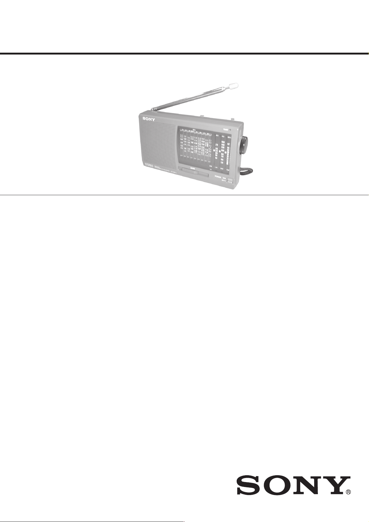
ICF-SW11
SERVICE MANUAL
Ver 1.1 2001. 10
SPECIFICATIONS
Frequency range:
FM: 87.5 – 108 MHz (Other models)
76 – 108 MHz (Tourist model)
SW1: 4.750 – 5.060 MHz (Other models)
3.850 – 4.050 MHz (Tourist model)
SW2: 5.900 –6.200 MHz
SW3: 7.100 – 7.350 MHz
SW4: 9.400 – 9.990 MHz
SW5: 11.600 – 12.100 MHz
SW6: 13.570 – 13.870 MHz
SW7: 15.100 – 15.800 MHz
SW8: 17.480 – 17.900 MHz
SW9: 21.450 – 21.750 MHz
MW: 525 – 1620 MHz
LW: 141 – 290 kHz
Speaker Approx. 5.7 cm (21/4 inches) dia., 4 Ω
Power output 140 mW (at 10 % harmonic distortion)
Ourput Headphones jack (stereo minijack, 3.5 mm dia)
US Model
Canadian Model
AEP Model
E Model
Chinese Model
Tourist Model
Power requirements
3 V DC, two R6 (size AA) batteries
DC IN 3V jack accepts : AC power adaptor
(Except chinese model)
AC-E30L, HG (not supplied)
Battery life Approx. 30 hours with Sony SUM-3 (NS)
Dimensions Approx. 162 × 93.8 × 34.8 mm(w/h/d)
(61/2 × 33/4 × 13/8 inches)
Mass Approx. 340 g (12 oz) incl. batteries
Supplied accessory
Short wave guide (1)
Accessories not supplied
AC power adaptor
*AC-E3L, HG
LW/MW/SW wide range antenna AN-1, AN-102
*The voltage of power supply is different depending on the country .
Please buy an AC power adaptor in the country where the radio is
to be used.
9-927-176-12
2001J1600-1
© 2001.10
Design and specifications are subject to change without notice.
FM STEREO/SW1-9/
MW/LW 12 BAND RECEIVER
Sony Corporation
Personal Audio Company
Published by Sony Engineering Corporation

TABLE OF CONTENTS
1. GENERAL ·········································································· 3
2. DISASSEMBLY
2-1. Rear Cabinet ··································································· 4
2-2. Front Cabinet, Main Board ············································· 4
2-3. Dial Pointer Setting ························································· 5
3. ELECTRICAL ADJUSTMENT ···································· 6
4. DIAGRAMS
4-1. IC Block Diagram ··························································· 8
4-2. Printed Wiring Board ······················································ 9
4-3. Schematic Diagram ······················································· 11
5. EXPLODED VIEWS ······················································ 13
6. ELECTRICAL PARTS LIST ······································· 14
— 2 —
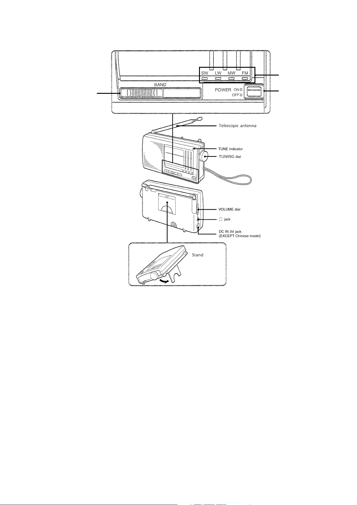
SECTION 1
GENERAL
BAND
indicator
BAND
select switch
POWER
switch
— 3 —
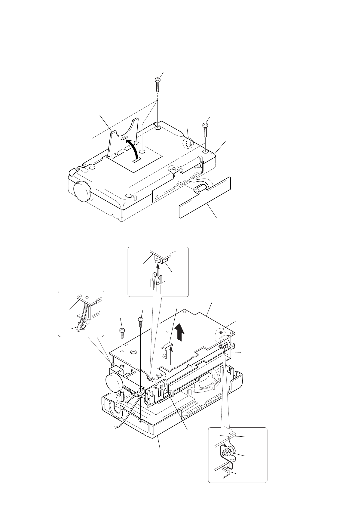
SECTION 2
d
s
DISASSEMBLY
Note : Follow the disassembly procedure in the numerical order given.
2-1. REAR CABINET
3 Three screws
(P2.6 × 16)
2 Stand
2-2. FRONT CABINET, MAIN BOARD
MAIN
board
5
S2
Claw
4 Two screws
(P2.6 × 16)
5 Cabinet (rear)
(The cabinet is locke
by the claws)
1 Lid, battery case
MAIN
board
D2
6
1 Screw
3 Screw
(BTP2.6 × 8)
(P2 × 8)
4 Terminal, battery
2 Front Cabinet
8 MAIN BOARD
Claw
Claw
Main chassi
MAIN
board
7 Terminal
(Minus),
battery
Main
chassis
— 4 —
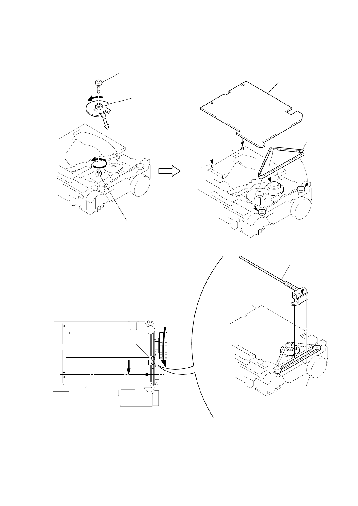
2-3. DIAL POINTER SETTING
7 First, turn the tuning shaft fully in the arrow A direction.
Move only the dial pointer in the arrow B direction and
set it on the center of the scratched lines on the dial scale plate.
Apply suitable locking compound to C portion.
6 Pointer
Knob (Tun)
Center of
scratched line
A
C
B
3 Screw
(1.7 × 3) Flat (+) special
A
5 Scale, dial
2 Mach the hole with setting
the variable capacitor gear gap
in the arrow A direction.
4 Belt (Tun)
1 Turn the variable capacitor
fully counterclockwise.
— 5 —
 Loading...