

Sony ICFF-11-S, ICFF-12-S Service manual
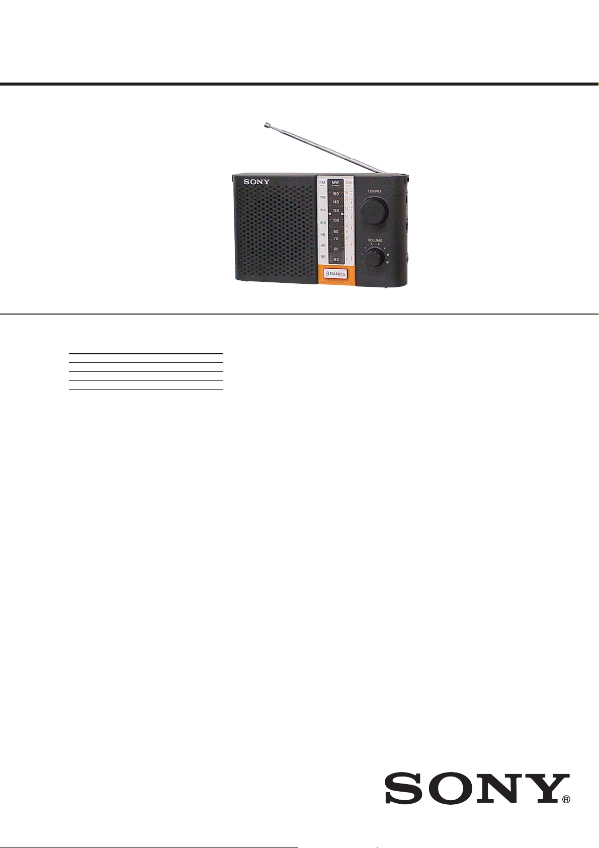
ICF-F11S/F12S
SERVICE MANUAL
Ver. 1.0 2007.11
Photo : ICF-F12S
SPECIFICATIONS
Frequency range:
Band ICF-F11S ICF-F12S
FM 87.5-108 MHz 87.5-108 MHz
MW 530-1 605 kHz 530-1 605 kHz
SW 2.3-7.35 MHz 5.9-18 MHz
Speaker
Approx. 9.2 cm (3
Output
v (earphone) jack (ø3.5mm minijack)
Power output
300 mW (max)
Power requirements
3V DC, two R20 (size D) batteries
Dimensions
Approx. 216 × 129.8 × 68.6 mm (w/h/d)
5
(8
/8× 5 1/8× 2 3/4 inches) incl. projecting parts and
controls
Mass
Approx. 676 g (1 lb 8 oz) incl. carrying strap and
batteries
Supplied accessories
carrying strap (1)
Design and specifications are subject to change
without notice.
5
/8 inches) dia., 4 Ω
E Model
Notes on chip component replacement
• Never reuse a disconnected chip component.
• Notice that the minus side of a tantalum capacitor may be damaged by heat.
9-887-911-01
2007K05-1
2007.11
©
FM/SW/MW 3 BAND RADIO
Sony Corporation
Audio Business Group
Published by Sony Techno Create Corporation
ICF-F11S/F12S
SERVICING NOTES
SECTION 1
SECTION 2
GENERAL
UNLEADED SOLDER
Boards requiring use of unleaded solder are printed with the leadfree mark (LF) indicating the solder contains no lead.
(Caution: Some printed circuit boards may not come printed with
the lead free mark due to their particular size)
: LEAD FREE MARK
Unleaded solder has the following characteristics.
• Unleaded solder melts at a temperature about 40 °C higher
than ordinary solder.
Ordinary soldering irons can be used but the iron tip has to be
applied to the solder joint for a slightly longer time.
Soldering irons using a temperature regulator should be set to
about 350 °C.
Caution: The printed pattern (copper foil) may peel away if the
heated tip is applied for too long, so be careful!
• Strong viscosity
Unleaded solder is more viscou-s (sticky, less prone to fl ow)
than ordinary solder so use caution not to let solder bridges
occur such as on IC pins, etc.
• Usable with ordinary solder
It is best to use only unleaded solder but unleaded solder may
also be added to ordinary solder.
HOW TO CHANGED THE CERAMIC FILTERS
This model is used two ceramic fi lters of CF1 and CF3.
You must used same type of color marked ceramic fi lters in order
to meet same specifi cations.
Therefore, the ceramic fi lter must be changed two pieces together
since it’s supply two pieces in one package as a spare parts.
CF1
mark
CF3
Mark Center frequency
red 10.70 MHz
blue 10.67 MHz
orange 10.73 MHz
black 10.64 MHz
white 10.76 MHz
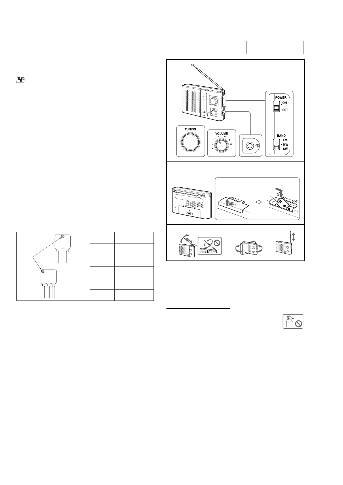
A
B
Rear
Parte posterior
FM MW SW
R20 (size D) × 2
R20 (tamaño D) × 2
Insert the E side of the battery first.
Inserte primero el lado E de la pila.
Installing the
batteries
(See fig. A)
Open the battery compartment lid.
1
2 Install two R20 (size D) batteries (not
supplied) with correct polarity.
3 Close the lid.
Battery life (Approx. hours) (JEITA*)
When using FM SW MW
Sony R20 (size D) 200 220 220
* Measured by JEITA (Japan Electronics and
Information Technology Industries Association)
Standards. The actual battery life may vary
depending on the circumstance of the unit.
When to replace the batteries
When the sound becomes weak or distorted, replace
all the batteries with new ones.
Notes on batteries
• Do not charge the dry batteries.
• Do not carry the dry batteries with coins or other
metallic objects. It can generate heat if the positive
and negative terminals of the batteries are
accidentally contacted by a metallic object.
• Do not use different types of batteries at the same
time.
• When you replace the batteries, replace all with new
ones.
• When you are not going to use the unit for a long
time, remove the batteries to avoid damage from
battery leakage and corrosion.
This section is extracted
from instruction manual.
Telescopic antenna
Antena telescópica
Improving the
reception
(See fig. B)
FM: Extend the telescopic antenna and adjust the
angle for optimum reception.
MW: Rotate the unit horizontally for optimum
reception. A ferrite bar antenna is built into the
unit.
SW: Extend the telescopic antenna vertically.
Note
Adjust the direction of the
antenna by holding the bottom of
it. The antenna can be damaged
when you move the antenna with
excessive force.
2
• This set can be disassembled in the order shown below.
3-1. DISASSEMBLY FLOW
ICF-F11S/F12S
SECTION 3
DISASSEMBLY
SET
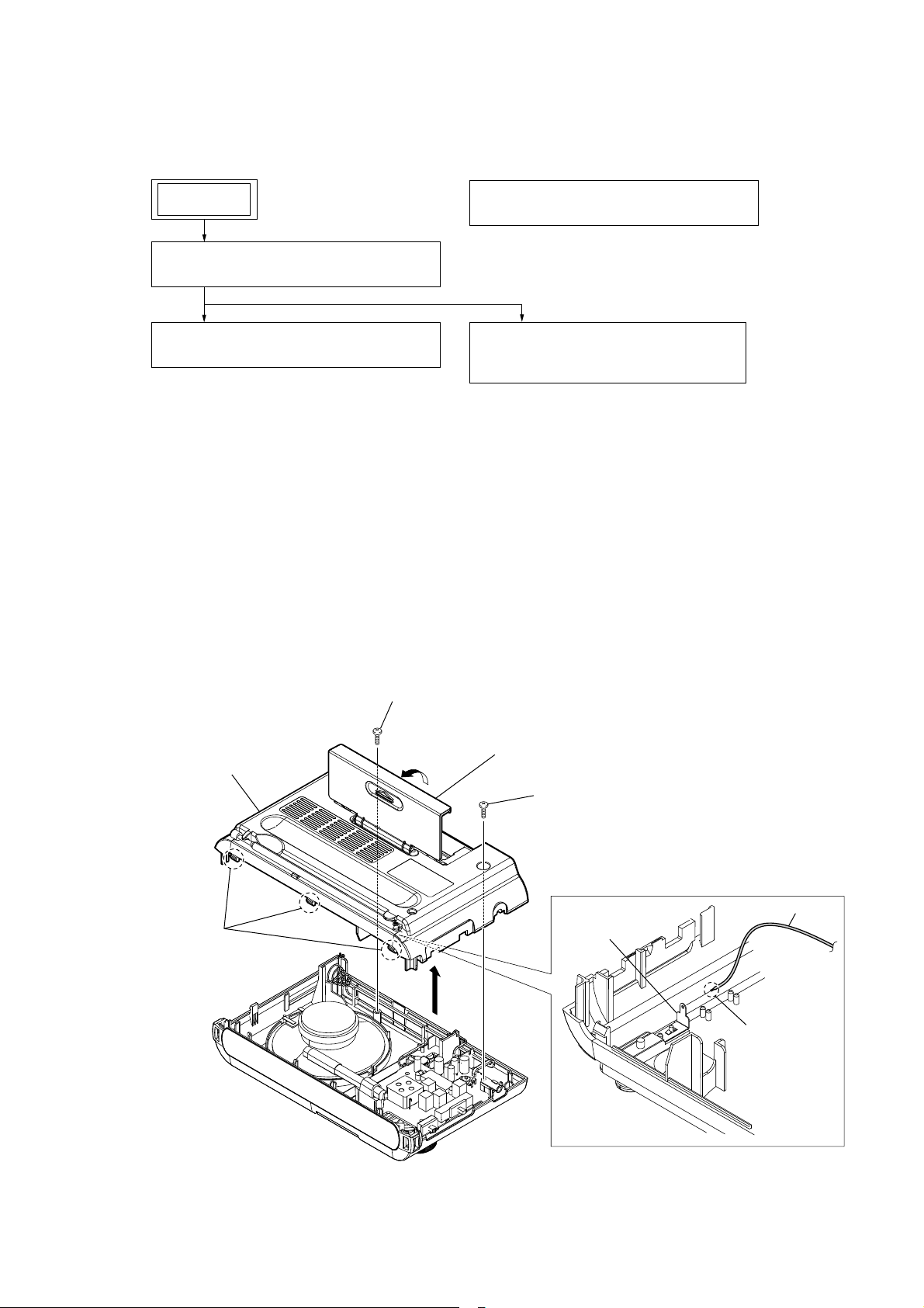
3-2. REAR CABINET BLOCK
(Page 3)
3-3. MAIN BOARD, GEAR (VC)
(Page 4)
Note: Follow the disassembly procedure in the numerical order given.
3-5. GEAR (VC) AND MAIN BOARD SETTING
(Page 5)
3-4. TELESCOPIC ANTENNA (ANT1),
BATTERY CASE LID, CABINET (REAR)
(Page 4)
3-2. REAR CABINET BLOCK
rear cabinet block
three claws
screw
Open the battery case lid.
screw
terminal board
(antenna)
antenna cable
Remove a
solder.
3
ICF-F11S/F12S
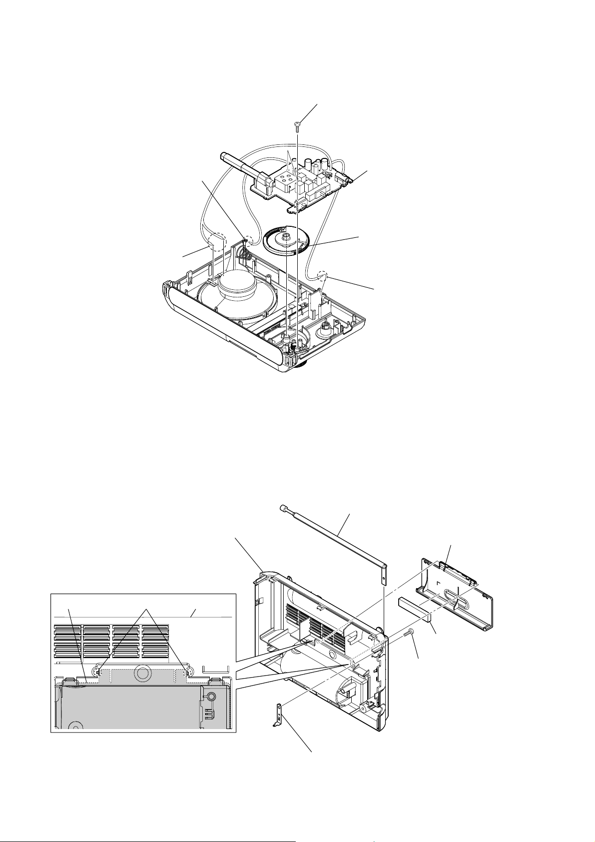
3-3. MAIN BOARD, GEAR (VC)
two screws
Remove a solder.
Remove two solders.
MAIN board
gear (VC)
Remove a solder.
3-4. TELESCOPIC ANTENNA (ANT1), BATTERY CASE LID, CABINET (REAR)
telescopic antenna (ANT1)
cabinet (rear)
battery case lid
two bosses
cabinet (rear)
terminal board (antenna)
battery case lid
cushion
(battery)
screw
(M3 × 6)
4
Note: Follow the assembly procedure in the numerical order given.
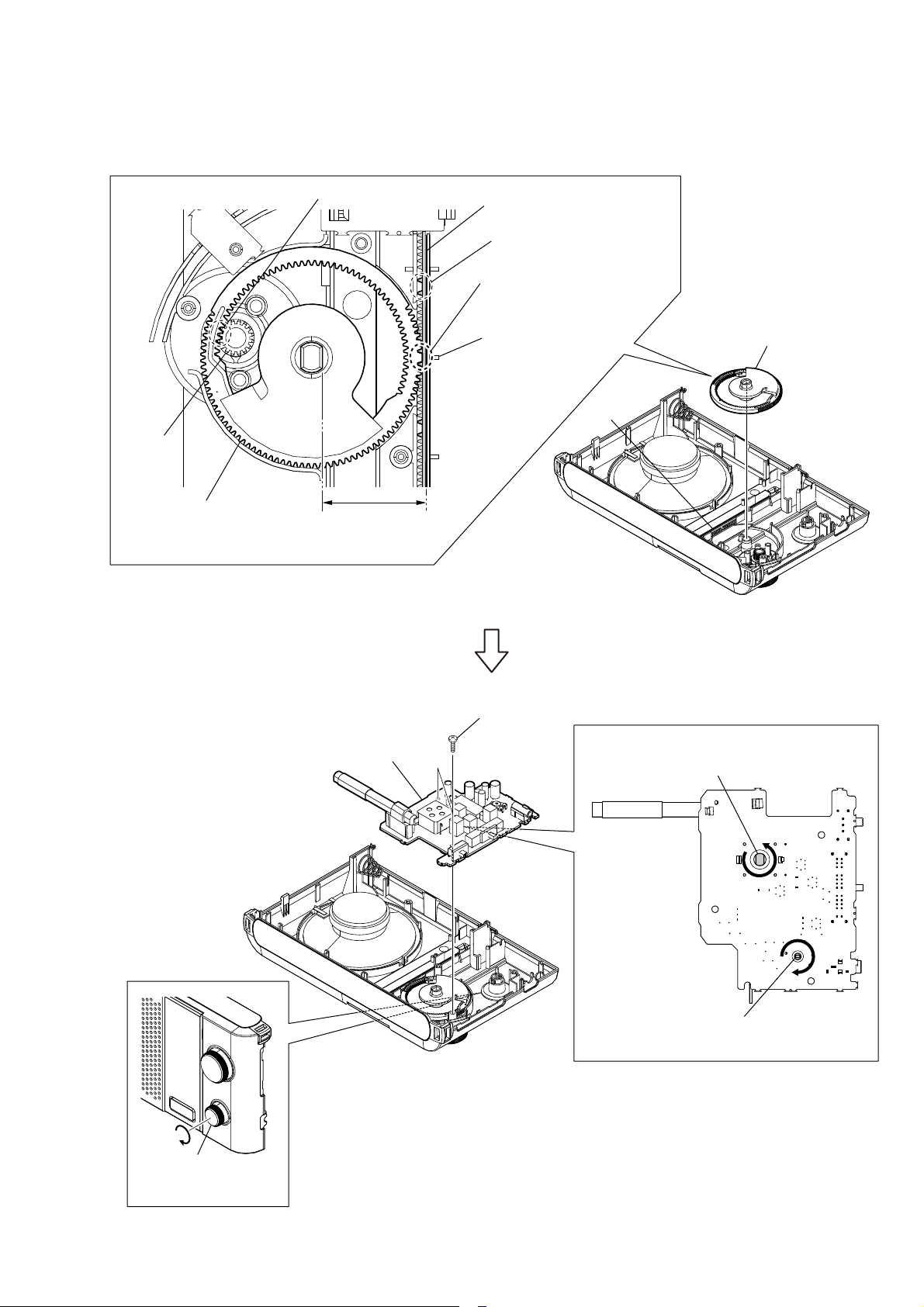
3-5. GEAR (VC) AND MAIN BOARD SETTING
ICF-F11S/F12S
Match two gears.
Down the pointer.
first concave portion
Set the second concave portion
of pointer to the convex part
of the gear (VC).
rib of front cabinet
knob (tune)
gear (VC)
The vicinity of hole at center
of gear (VC) and the pointer
must be parallel.
Note: Match the convex part of the gear (VC) to the second concave portion of pointer
with pointer lowered most.
Install the gear (VC)
as shown in figure.
pointer
Rotate knob (VOL)
in the direction
of the arrow fully.
MAIN board
two screws
Rotate the shaft of CV1 in the direction
of the arrow fully.
Rotate the shaft of RV1 in the direction
of the arrow fully.
5
 Loading...