

Sony ICD-P520,ICD-P530F Service Manual
SERVICE MANUAL
Published by Sony Techno Create Corporation
Sony Corporation
Personal Audio Division
ICD-P520/P530F
SPECIFICATIONS
IC RECORDER
9-887-636-02
2007F04-1
©
2007.06
US Model
ICD-P520/P530F
Canadian Model
ICD-P520
AEP Model
UK Model
E Model
ICD-P520/P530F
Chinese Model
ICD-P520
Ver. 1.1 2007.06
IC recorder section
Recording media
recording
Actual usable capacity may be smaller.
Recording time
HQ: 29 hours 45 minutes
SP: 79 hours 20 minutes
LP: 130 hours 25 minutes
Freqency range
HQ: 260 Hz - 6,800 Hz
SP/LP: 220 Hz - 3,400 Hz
FM radio section (P530F)
Frequency range
87.5 - 108 MHz
IF 225 kHz
Antennas
Headphone cord antenna
General
Speaker
Approx. 2.8 cm (1 1/8 in.) dia.
Power output
250 mW
Input/Output
Headphone jack (minijack) for 8 - 300 ohms
ear receiver/headphones
[
Microphone jack (minijack, monaural)
Plug in power
Minimum input level 0.6 mV
3kilohms or lower impedance microphone
USB connector
Powerrequirements
Two LR03 (size AAA) alkaline batteries: 3 V DC
Dimensions (w/h/d) (not incl.
projecting parts and controls)
34.6 × 109.5 × 18.0 mm (1 3/8 × 4 3/8 × 23/32
in.)
Mass (incl. batteries)
68 g (2.4 oz)
Supplied accessories
Operating instructions (1)
LR03 (size AAA) alkaline batteries (2)
Headphone (1) (P520: E, CH, KR/P530F)
Carrying pouch (1) (E, CH, KR model)
USB connecting cable (1)
Application software (CD-ROM) (1)
change without notice.
[
[
• Abbreviation
CH : Chinese model
KR : Korea model

ICD-P520/P530F
2
1. GENERAL .................................................................. 3
2. DISASSEMBLY
2-1. Case (Front) Assy ............................................................ 4
2-2. Main Board ..................................................................... 5
2-3. USB Board (P520), USB/FM Board (P530F) ................ 5
3. TEST MODE ............................................................. 6
4. DIAGRAMS
4-1. Block Diagram ................................................................ 9
4-2. Printed Wiring Board – MAIN Section – ....................... 11
4-3. Schematic Diagram – MAIN Board (1/2) – .................... 12
4-4. Schematic Diagram – MAIN Board (2/2) – .................... 13
4-5. Printed Wiring Board
– USB/FM Section (ICD-P530F) – ................................ 14
4-6. Printed Wiring Board – USB Section (ICD-P520) – ...... 15
4-7. Schematic Diagram
– USB/FM Section (ICD-P530F) – ................................ 16
4-8. Schematic Diagram – USB Section (ICD-P520) – ......... 16
5. EXPLODED VIEWS
5-1. Case (Front) Section ....................................................... 19
5-2. Case (Rear) Section ........................................................ 20
6. ELECTRICAL PARTS LIST ................................. 21
TABLE OF CONTENTS
UNLEADED SOLDER
Boards requiring use of unleaded solder are printed with the leadfree mark (LF) indicating the solder contains no lead.
(Caution: Some printed circuit boards may not come printed with
the lead free mark due to their particular size)
: LEAD FREE MARK
Unleaded solder has the following characteristics.
• Unleaded solder melts at a temperature about 40 °C higher
than ordinary solder.
Ordinary soldering irons can be used but the iron tip has to be
applied to the solder joint for a slightly longer time.
Soldering irons using a temperature regulator should be set to
about 350 °C.
Caution: The printed pattern (copper foil) may peel away if the
heated tip is applied for too long, so be careful!
• Strong viscosity
Unleaded solder is more viscou-s (sticky, less prone to fl ow)
than ordinary solder so use caution not to let solder bridges
occur such as on IC pins, etc.
• Usable with ordinary solder
It is best to use only unleaded solder but unleaded solder may
also be added to ordinary solder.
Notes on chip component replacement
• Never reuse a disconnected chip component.
• Notice that the minus side of a tantalum capacitor may be damaged by heat.
Flexible Circuit Board Repairing
• Keep the temperature of soldering iron around 270 °C during
repairing.
• Do not touch the soldering iron on the same conductor of the
circuit board (within 3 times).
• Be careful not to apply force on the conductor when soldering
or unsoldering.
ICD-P520/P530F
3
SECTION 1
GENERAL
This section is extracted
from instruction manual.
6
GB
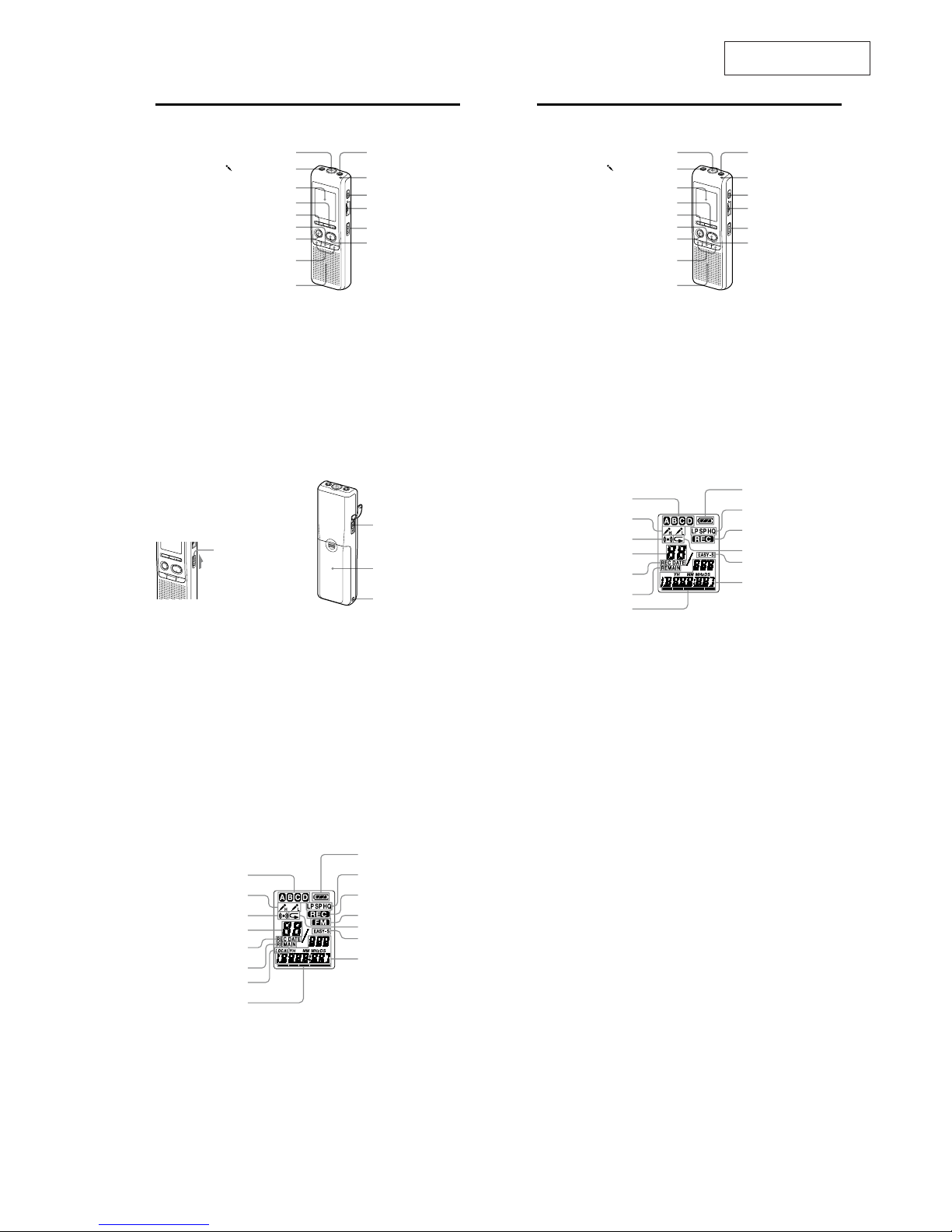
Index to Parts and Controls
Main unit (ICD-P520)
MIC (built-in microphone)
(microphone) jack
Display window
DISPLAY/MENU
DIVIDE
YSTOP
[9REC (record) /PAUSE
–
(review/fast backward)
/
+
(cue/fast forward)
(SELECT)
Speaker
J (headphone) jack
OPR (operation) indicator
ERASE
VOL (volume) control*
HOLD
/YPLAY/STOP (ENTER)**
*There is a tactile dot beside the controlto show
the direction to turn up the volume.
** The button has a tactile dot.
6
GB
Index to Parts and Controls
Main unit (ICD-P530F)
MIC (built-in microphone)
(microphone) jack
Display window
DISPLAY/MENU
FM•J (headphone)/ (speaker) selector
YSTOP
[9REC (record) /PAUSE
–
(review/fast backward)
/
+
(cue/fast forward)
(SELECT)
Speaker
J (headphone) jack
OPR (operation) indicator
DIVIDE
VOL (volume) control*
HOLD
/YPLAY/STOP (ENTER)**
*There is a tactile dot beside the controlto show
the direction to turn up the volume.
** The button has a tactile dot.
7
GB
Preventing Accidental Operation
— HOLD function
Slide the HOLD switch to“ON”. “HOLD ” will
ash three times, indicating that all the
functions of the buttons are locked.
When the HOLD function is activated during
stop, all the display will be turned o after
“HOLD” ashes.
HOLD
To cancel the HOLD function
Slide the HOLD switch to“OFF” .
Note
When the HOLD function is activated during
recording, cancel the HOLD function rst to
stop recording.
Tip
Even if the HOLD function is activated, you can
stop the alarm playback. To stop the alarm or
playback, press YSTOP.
1
[
Rear
USB connector
Battery compartment
Hook for handstrap
(not supplied)
8
GB
Display window (ICD-P520)
Folder indication
Microphone sensitivity
Alarm indicator
Selected message
number
REC DATE (recorded date)
indication
REMAIN indicator
Remaining memory
indicator
Remaining battery
indicator
Recording mode
indication
REC (recording)
indicator
Repeat play indicator
EASY-S (Easy Search)
indicator
Number of messages
in a folder/Menu
indication/Counter/
Remaining time
indication /Recording
date indication/
Current time indication/
Messages
8
GB
Display window (ICD-P530F)
Folder indication
Microphone sensitivity
Alarm indicator
Selected message
number
REC DATE (recorded date)
indication
REMAIN indicator
FM radio sensitivity
Remaining memory
indicator
Remaining battery
indicator
Recording mode
indication
REC (recording)
indicator
FM indicator
Repeat play indicator
EASY-S (Easy Search)
indicator
Number of messages
in a folder/Menu
indication/Counter/
Remaining time
indication /Recording
date indication/
Current time indication/
Messages
ICD-P520/P530F
4
SECTION 2
DISASSEMBLY
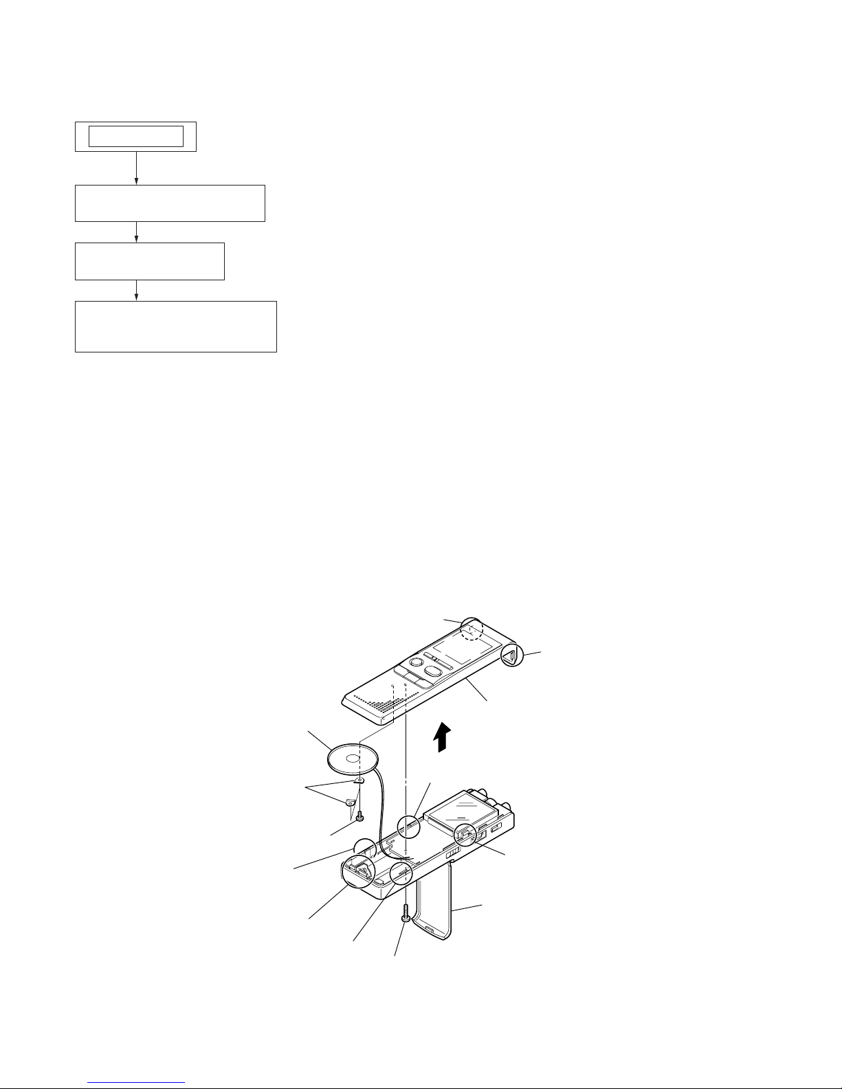
• This set can be disassembled in the order shown below.
Note: Follow the disassembly procedure in the numerical order shown below.
2-1. CASE (FRONT) ASSY
2-1. CASE (FRONT) ASSY
(Page 4)
2-2. MAIN BOARD
(Page 5)
SET
2-3. USB BOARD (P520),
USB/FM BOARD (P530F)
(Page 5)
R
screw
RB two screws
RT two brackets (speaker)
RE speaker
RG case (front) assy
claw
claw
claw
claw
two claws
battery case lid
claw
claw

ICD-P520/P530F
5
2-2. MAIN BOARD
2-3. USB BOARD (P520), USB/FM BOARD (P530F)
MAIN board
S701
CN2001
insulating sheet
screw
USB board (P520),
USB/FM board (P530F)
two screws
ICD-P520/P530F
6
SECTION 3
TEST MODE
1. Outline of the TEST MODE
The TEST MODE is designed to help verify the set when servicing it.
The TEST MODE is only menu driven to select modes for servicing.
2. Entering and Canceling the TEST MODE
With the power on, turn on the [HOLD] switch while pressing the
[xSTOP] button and the [DISPLAY/MENU] button at the same
time.
3. Canceling the TEST MODE
The TEST MODE can be cancelled by turning off the power (unplugging the dry battery).
4. Menu Key Designation
The menu has the fi ve modes described below. The following keys
are assigned on the initial screen (version display).
5. Key Assignment
From within TEST MODE, the intended menu can be entered by
using the appropriate one key of the following key.
LCD Test (All OnyAll Off) DISPLAY/MENU
BEEP Test (1.3 kHz)
ERASE (P520)
FM•i/5 (P530F)
HQ-DSP LOOP
zXREC/PAUSE
SP-DSP LOOP
– .
LP-DSP LOOP
> +
USB Test
NxPLAY/STOP(ENTER)
REST MENU Test DIVIDE
Initial Display from each mode
xSTOP
5-1. Initial Display in TEST MODE
LCD indications (destination information, memory capacity, CPU
FW information and MIC sens) when TEST MODE is entered:
Memory capacity
(256-256 MB)
MIC sens
Destination
information
CPU FW information
5-2. LCD Test
To enter the LCD Test, press the [DISPLAY/MENU] button. The
LCD Test has two modes: All On and All Off First all the indicators are on. All the indicators are off when the button is pressed
again.
ALL ON
DISPLAY/MENU
Switch between
the modes.
ALL OFF
Press the [xSTOP] button to return to the initial display (destination information, memory capacity, CPU FW information and
MIC sens).
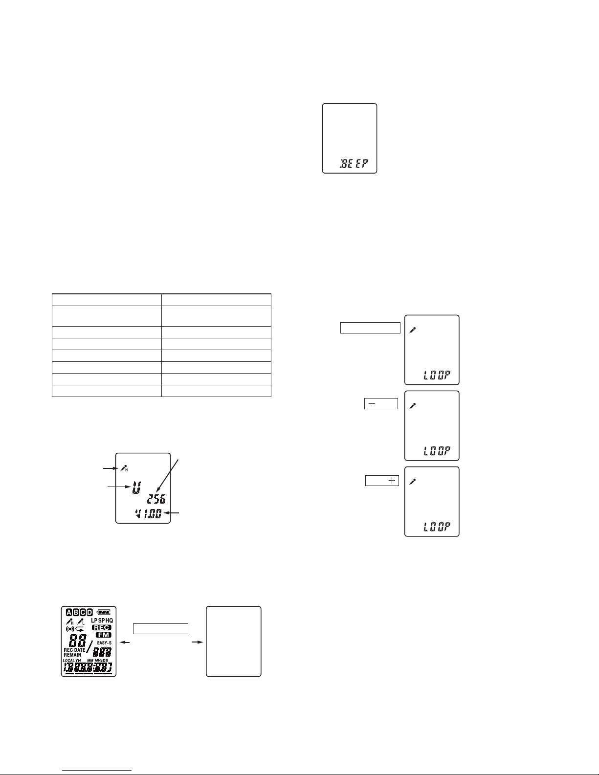
5-3. BEEP Test
To enter the BEEP Test, press the [ERASE] (P520), [FM•i/
5
]
(P530F) button.
Beep: Frequency 1.3 kHz only
Press the [xSTOP] button to return to the initial screen (memory
and CPU version).
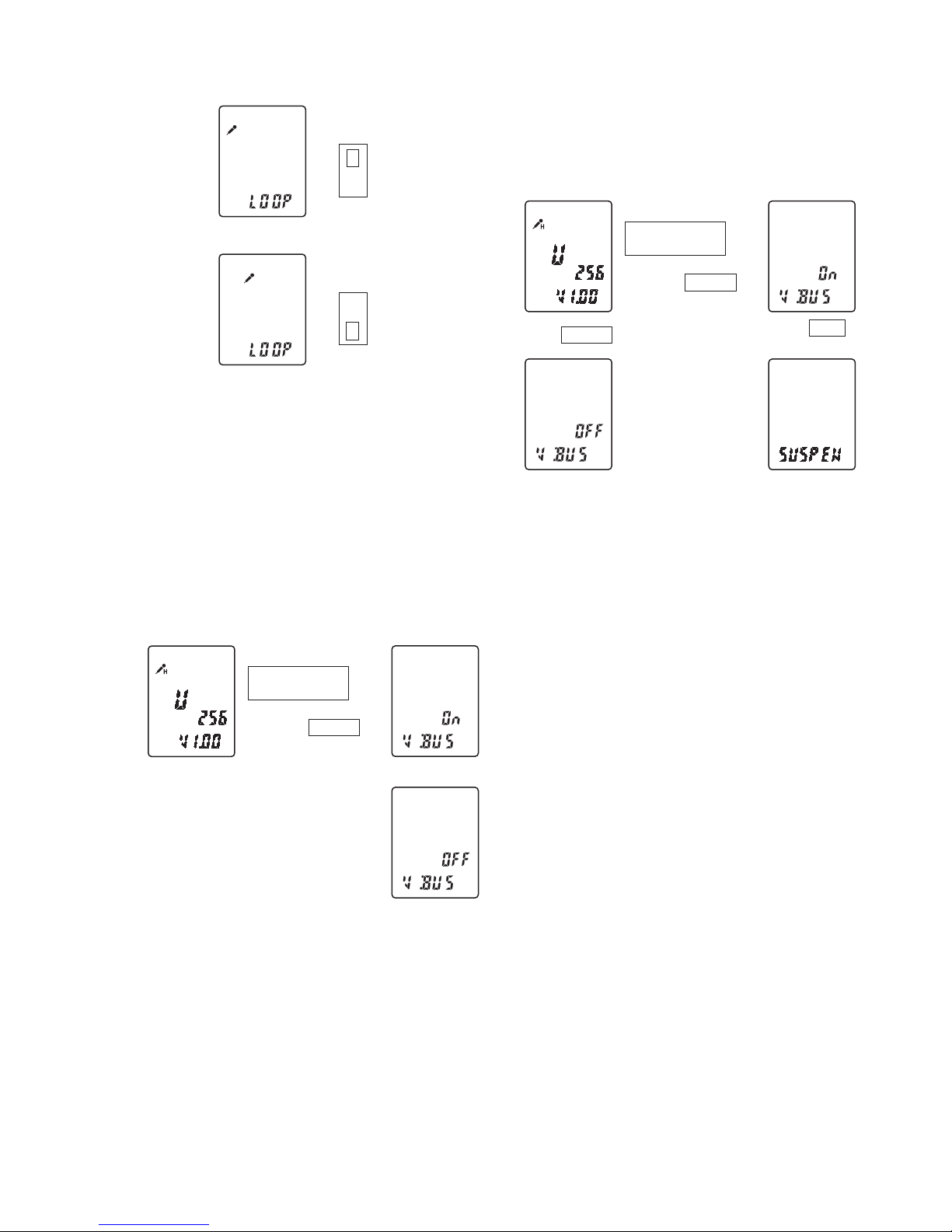
5-4. DSP LOOP
The DSP LOOP modes can be entered selectively by pressing the
appropriate one of the following three keys.
Within the LOOP test menu, “LOOP” is displayed. The sensitivity
character H or L is displayed depending on the position into which
the [HOLD] switch is placed.
The sensitivity H is displayed when [HOLD] switch is in the ON
position. The sensitivity L is displayed when [HOLD] switch is in
the OFF position.
[9 REC/PAUSE
HQ
H
LP
H
SP
H
To change the DSP LOOP test mode, press the [xSTOP] button, then select the [zXREC/PAUSE] button, [– .] button, or
[> +] button.
In a DSP Test mode, to select another DSP T est mode and to select
the other sensitivity, the [xSTOP] button also has to be pressed.
ICD-P520/P530F
7
Sensitivity H
HOLD
ON
OFF
H
Sensitivity L
HOLD
L
To change the sensitivity again, press the [xSTOP] button and
change the [HOLD] switch.
In a DSP Test mode, changing the mode and changing the sensitivity require the [xSTOP] button be pressed.
5-5. USB Test
In this test, the ON/OFF status of VBUS is displayed and the SUSPEND test is performed.
The [
Nx
PLAY/STOP(ENTER)] button is pressed to display the
status of VBUS by “On” or “OFF” indication.
With the VBUS ON, the [HOLD] switch is operated (ON) to perform the SUSPEND test.
• VBUS T est
/YPLAY/STOP
(ENTER)
L
,
YSTOP
with VBUS
without VBUS
• SUSPEND Test
With the VBUS ON, turn the [HOLD] switch ON to enter the SUSPEND mode.
When this mode is cancelled, the VBUS is turned OFF.
/YPLAY/STOP
(ENTER)
VBUS OFF
L
,
,
K
YSTOP
YSTOP
HOLD
ON
+
with VBUS
SUSPEND mode
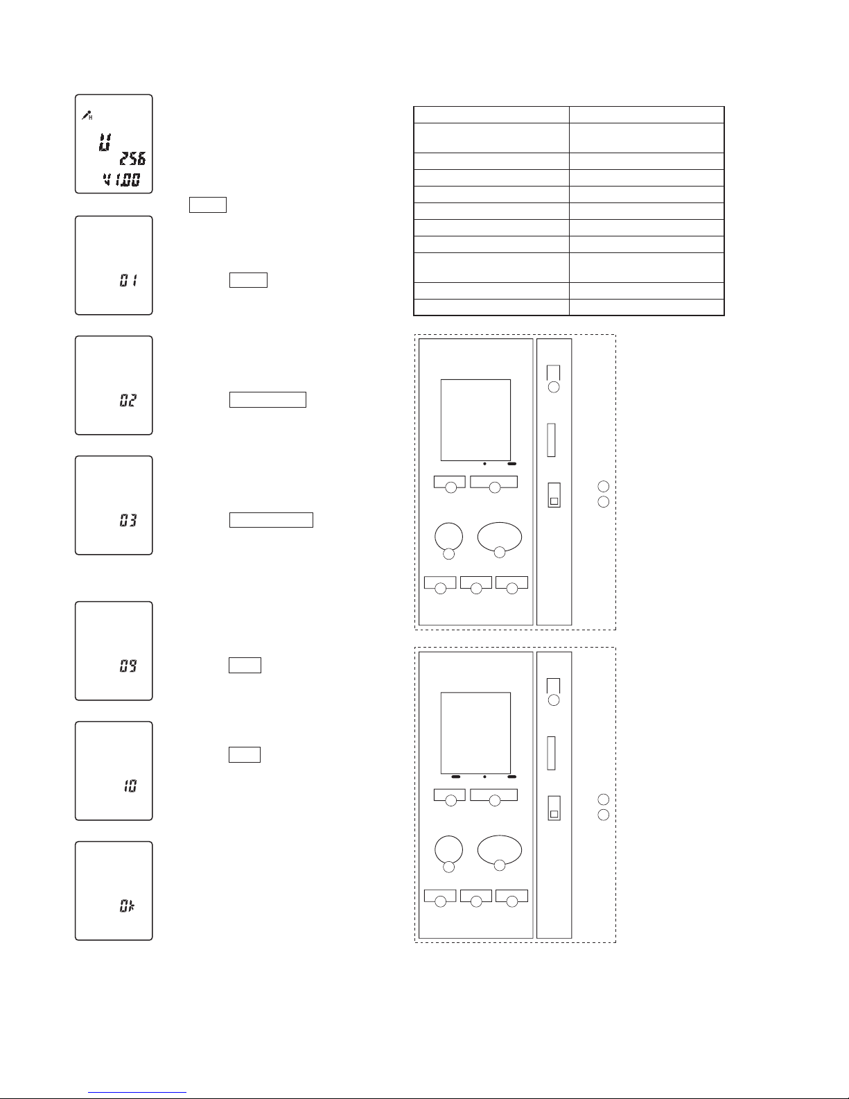
5-6. RESET MENU
To enter the RESET MENU test, press the [DIVIDE] button.
When all of the buttons or controls located on the set are operated,
the system shows “Ok” if all of them are normally operated.
An operation of a switch is indicated by the number for verifi cation
in order to make a simple indication.
Note 1: When 10 different operations of the switches are normally made
in any order (regardless of the order that pushbuttons are pressed
and the slide switch is set to ON and OFF), the system shows
“Ok”.
Note 2: Clear memory when “ACCESS” is blinking on the display. (Do
this before “Ok” is shown.) To exit from this menu, the power has
to be turned off (battery to be removed).
ICD-P520/P530F
8
• Switches and corresponding LCD indications
Switch Indication
DIVIDE (P520)
FM•i/5 (P530F)
1
DISPLAY/MENU 2
zXREC/PAUSE
3
NxPLAY/STOP(ENTER)
4
– .
5
xSTOP
6
> +
7
ERASE (P520)
DIVIDE (P530F)
8
HOLD-OFF 9
HOLD-ON 10
1 2
8
10
3
4
5 6 7
DIVIDE
REC/PAUSE
STOP
+–
PLAY/STOP(ENTER)
ERASE
VOL
HOLD
ON
9
OFF
DISPLAY/MENU
P520
1 2
8
10
3
4
5 6 7
FM J/
REC/PAUSE
STOP
+–
PLAY/STOP(ENTER)
DIVIDE
VOL
HOLD
ON
9
OFF
P530F
DISPLAY/MENU
S
S
Press DIVIDE button.
Indication after DIVIDE
button is pressed.
Indication after DISPLAY/MENU
button is pressed.
Indication after [9 REC/PAUSE
button is pressed.
Indication after HOLD is
set to OFF.
Indication after HOLD is
set to ON.
UIf any key is not pressed,
the system waits for the key
to be pressed.
Clear memory when "ACCESS" is
blinking on the display.
The system shows "Ok".
••••••
S
S
S
 Loading...