

Page 1

4-599-313-11(1)
Solid-State Memory
Camcorder
Operating Guide
Identifying Parts and
Controls
Getting Started
Recording
Playback
Using Network Functions
Editing
Using the Menu
Troubleshooting
Additional Information
HXR-NX5R
®
Page 2
Read this first
Before operating this unit, please read this manual thoroughly, and retain it for future
reference.
Precautions when using the
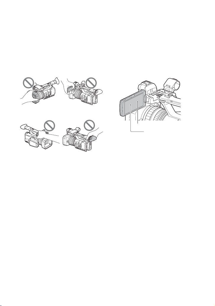
camcorder
• Do not hold the camcorder by the following
parts, and also do not hold the camcorder by the
jack covers.
black points and/or bright points (white, red,
blue, or green in color) that appear constantly on
the LCD screen. This is not a malfunction.
These points are normal results of the
manufacturing process and do not affect the
recording in any way.
Lens cover with
LCD screen
hood
ViewfinderMicrophone (sold
separately) or
Microphone holder
b Notes
• The camcorder is not dustproof, dripproof or
waterproof. See “About handling of your
camcorder” (p. 135).
• When connecting the camcorder to another
device with communication cables, be sure to
insert the connector plug in the correct way.
Pushing the plug forcibly into the terminal will
damage the terminal and may result in a
malfunction of the camcorder.
• Use the camcorder in accordance with the
regulations of a place where you use it.
On the LCD screen and lens
• A menu item that is grayed out is not available
under the current recording or playback
conditions.
• The LCD screen is manufactured using
extremely high-precision technology, so over
99.99% of the pixels are operational for
effective use. However, there may be some tiny
2
White, red, blue or green point
Black point
On sunlight
• Do not record the sun or leave the camcorder
under the sun for a long time. The internal parts
of the camcorder may be damaged. If sunlight is
focused on a nearby object, it may cause a fire.
• Do not expose your camcorder’s viewfinder,
lens, or LCD screen to the sun or strong light
source for extended periods. Doing so may
cause a malfunction of the camcorder.
• Do not attempt to record the sun directly. Doing
so may cause a malfunction of the camcorder.
• Do not expose the lens to beams, such as laser
beams.
That may damage the image sensor and cause
the camera to malfunction.
On the temperature of your camcorder
and battery pack
Your camcorder has a protective function that
disables recording or playback if the temperature
of your camcorder or battery pack is beyond the
safely operable range. In this case, a message
appears on the LCD screen or in the viewfinder
(p. 121).
On recording
• In order to stabilize memory card operation, it is
recommended that you format the memory card
when you use it with your camcorder for the
Page 3

first time. All data recorded on the memory card
will be erased by formatting, and cannot be
recovered. Save important data on the memory
card on other media, such as a computer, before
formatting the memory card.
• Before starting to record, test the recording
function to make sure the picture and sound are
recorded without any problems.
• Compensation for the loss of the content of
recordings or the loss of recording opportunities
cannot be provided, even if recording or
playback is not possible due to a malfunction of
the camcorder, storage media, etc., or even if
images or sounds are distorted due to the limits
of the capabilities of the camcorder.
• TV color systems differ depending on the
countries/regions. To view your recordings on a
TV, a TV of the appropriate color system for the
country/region is required.
• Television programs, films, video tapes, and
other materials may be copyrighted.
Unauthorized recording of such materials may
be contrary to the copyright laws.
• Because of the way that the image device
(CMOS sensor) reads out image signals, the
following phenomena may occur.
– The subjects passing by the frame rapidly
might appear crooked depending on the
recording conditions. (This phenomenon may
be notable in displays having high motion
resolution.)
– Horizontal lines appear on the LCD screen
during recording under fluorescent lights,
sodium lamps or mercury lamps. The
phenomena can be reduced by adjusting the
shutter speed (p. 40 ).
on that memory card may become fragmented. As
a result, you may not be able to record and save
images properly. If this happens, save images on a
PC, then format the memory card (p. 83).
This camcorder does not have a
function for switching the signal
format (60i/50i).
In this manual, the values for both the “60i
model” and “50i model” are described. Check the
signal format of your camcorder on the display
screen (p. 15).
About this manual
• The on-screen display in English is used for
illustrating the operating procedures. Change
the screen language before using your
camcorder if necessary.
• Design and specifications of recording media
and other accessories are subject to change
without notice.
Save all your recorded image data
• To prevent your image data from being lost,
save all your recorded images periodically.
To handle the recorded images on
your computer
Download software (p. 18).
Format the memory card using
[MEDIA FORMAT] if images are not
recorded or played back properly
If you continue recording and deleting images on
a memory card for a long period of time, the files
3
Page 4

Table of Contents
Read this first ........................................................................................... 2
Identifying Parts and Controls
Identifying Parts and Controls ..................................................................8
Body ..................................................................................................... 8
Wireless Remote Commander ............................................................ 14
Screen Indicators ................................................................................... 15
Getting Started
Step 1: Checking supplied accessories .................................................17
Step 2: Charging the battery pack ......................................................... 19
Step 3: Attaching the microphone, lens cover with hood, and video
light diffuser ................................................................................... 22
Step 4: Attaching the accessory shoe ....................................................24
Step 5: Turning on the camcorder and setting the date and time .......... 25
Turning on the camcorder .................................................................. 25
Setting the date and time ................................................................... 25
Step 6: Adjusting the LCD screen and viewfinder ..................................27
Using the LCD screen ........................................................................ 27
Using the viewfinder ........................................................................... 27
Adjusting the viewfinder diopter ......................................................... 27
Switching between LCD screen display and viewfinder display ....... 28
Step 7: Inserting a memory card ............................................................ 29
Supported memory cards .................................................................. 29
Inserting a memory card .................................................................... 29
Recording
Recording ............................................................................................... 31
Adjusting the focus .................................................................................35
Recording ...........................................................................................31
Continuous recording on the memory cards (Relay Rec) ..................32
Recording movies using both memory card A and B (Simul Rec) ....33
Changing the START/STOP button/handle record button setting ...... 33
Adjusting the zoom ............................................................................. 34
Using automatic focus/fixed focus temporarily (Push auto focus/
Focus hold) .........................................................................................35
Focusing using the focus magnifier ...................................................35
Focusing on a distant subject (Infinite focus) ....................................36
Focusing on a detected face (Face detection) .................................. 36
4
Page 5

Selecting the file format and recording format ........................................38
Setting the file format and recording format ...................................... 38
Setting DV MODE (DV mode) ............................................................ 38
Adjusting the brightness .........................................................................39
Adjusting the iris ................................................................................ 39
Adjusting the gain .............................................................................. 40
Adjusting the shutter speed ............................................................... 40
Adjusting the light level (ND filter) ...................................................... 41
Adjusting the color tone ..........................................................................42
Adjusting the white balance ............................................................... 42
Using Direct Menu ..................................................................................44
Audio setup ............................................................................................46
Recording sound from the internal microphone ................................ 46
Recording sound from an external audio device ............................... 47
Recording sound from a Multi Interface Shoe compatible
microphone (sold separately) ............................................................ 47
Setting the audio recording level ....................................................... 48
Setting the headphone sound ............................................................ 48
Useful functions ......................................................................................49
Shooting in dimly lit locations (Video light) ........................................ 49
Selecting suitable settings automatically (auto mode setting) ........... 50
Customizing the picture quality (Picture Profile) ................................ 51
Setting time data ................................................................................ 51
Recording with the Slow & Quick Motion function ............................. 52
Reviewing the most recently recorded scene (Last Scene
Review) .............................................................................................. 53
Assigning functions to the ASSIGN buttons ...........................................54
Playback
Playback .................................................................................................55
Playback ............................................................................................ 55
Changing/checking the settings in your camcorder ................................58
Changing the screen display ............................................................. 58
Displaying recording data (Data Code) ............................................. 58
Checking the settings in your camcorder (Status Check) ................. 59
Connecting to a monitor or a TV ............................................................60
Selecting jacks for external output ..................................................... 60
Output signal formats ......................................................................... 62
Using Network Functions
Using with a Smartphone .......................................................................65
Downloading “Content Browser Mobile” ............................................ 65
Using a smartphone as a remote controller ....................................... 65
Continued ,
5
Page 6

Table of Contents (Continued)
Connecting the camcorder to an Android smartphone equipped with
the NFC function using One-touch .....................................................66
Connecting without using the NFC function (Android) ....................... 67
Connecting without using the NFC function (iPhone/iPad) ................67
Configuring a wireless LAN ....................................................................68
Configuring a wired LAN ........................................................................72
Using the streaming function (STREAMING) .........................................73
Streaming movies using USTREAM ...................................................... 75
Using the FTP transfer function .............................................................77
Importing a root certificate ..................................................................... 79
Resetting network settings .....................................................................80
Selecting and registering an access point ......................................... 68
Registering an access point using the WPS function ........................ 68
Registering an access point using the WPS PIN method .................. 69
Registering an access point manually ............................................... 70
Changing the device name ................................................................ 71
Streaming formats .............................................................................. 73
Configuring streaming (preset registration) ....................................... 73
Streaming distribution ........................................................................ 73
Configuring USTREAM authentication ............................................... 75
Using the menu .................................................................................. 75
Starting USTREAM ............................................................................. 75
Stopping USTREAM ........................................................................... 77
Registering an FTP server .................................................................. 77
Selecting an FTP server ..................................................................... 78
Using FTP transfer .............................................................................. 78
Checking FTP transfer results ............................................................ 79
Editing
Protecting movies (Protect) .................................................................... 81
Dividing a movie .....................................................................................81
Deleting movies .....................................................................................82
Formatting a memory card .....................................................................83
Deleting all data from the memory card completely ............................... 83
Repairing the image database file ......................................................... 84
Using the Menu
Operating the menu ...............................................................................85
Menu items ............................................................................................86
6
CAMERA SET menu ........................................................................... 88
REC/OUT SET menu ........................................................................... 92
AUDIO SET menu ............................................................................... 97
Page 7

DISPLAY SET menu ........................................................................... 99
TC/UB SET menu ............................................................................. 102
NETWORK SET menu ...................................................................... 103
OTHERS menu ................................................................................. 105
EDIT menu ....................................................................................... 106
PICTURE PROFILE menu ................................................................. 107
Troubleshooting
Troubleshooting ....................................................................................114
Warning indicators and messages .......................................................121
Additional Information
Recording time .....................................................................................125
Function limitations when recording .....................................................127
Streaming supported formats ...............................................................128
USTREAM supported formats ..............................................................129
Using your camcorder abroad ..............................................................130
File/folder structure on the recording media .........................................131
Maintenance and precautions ..............................................................133
Specifications .......................................................................................138
Index .....................................................................................................141
Limitations for each file format ......................................................... 127
Slow & Quick Motion recording limitations ....................................... 127
About the XAVC S format ................................................................. 133
About the AVCHD format ................................................................. 133
About memory cards ....................................................................... 133
About the “InfoLITHIUM” battery pack ............................................ 134
About handling of your camcorder .................................................. 135
7
Page 8
Identifying Parts and Controls
Identifying Parts and Controls
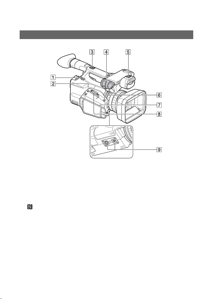
Body
The numbers in ( ) are reference pages.
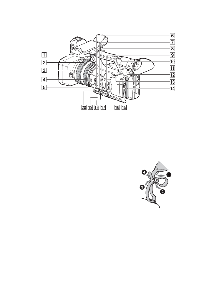
A Hook for shoulder strap
B ASSIGN6/FOCUS MAG button (p. 35)
C Accessory shoe mount (p. 24)
D Microphone holder (p. 22)
E Multi Interface Shoe
F ASSIGN7/Fn button (p. 44)
G (N mark)
• Touch an NFC-enabled smartphone to
the mark to establish a connection
with the camcorder.
• Near Field Communication (NFC) is
an international standard for shortrange wireless communication
technology.
H Power zoom lever (p. 34)
8
I Tripod receptacles (1/4 inch, 3/8 inch)
Supports 1/4-20UNC and 3/8-16UNC
screws.
For mounting on a tripod (sold
separately, screw length 5.5 mm or
shorter)
The tripod may not be able to mount in
some orientations, depending on the
tripod specifications.
Page 9
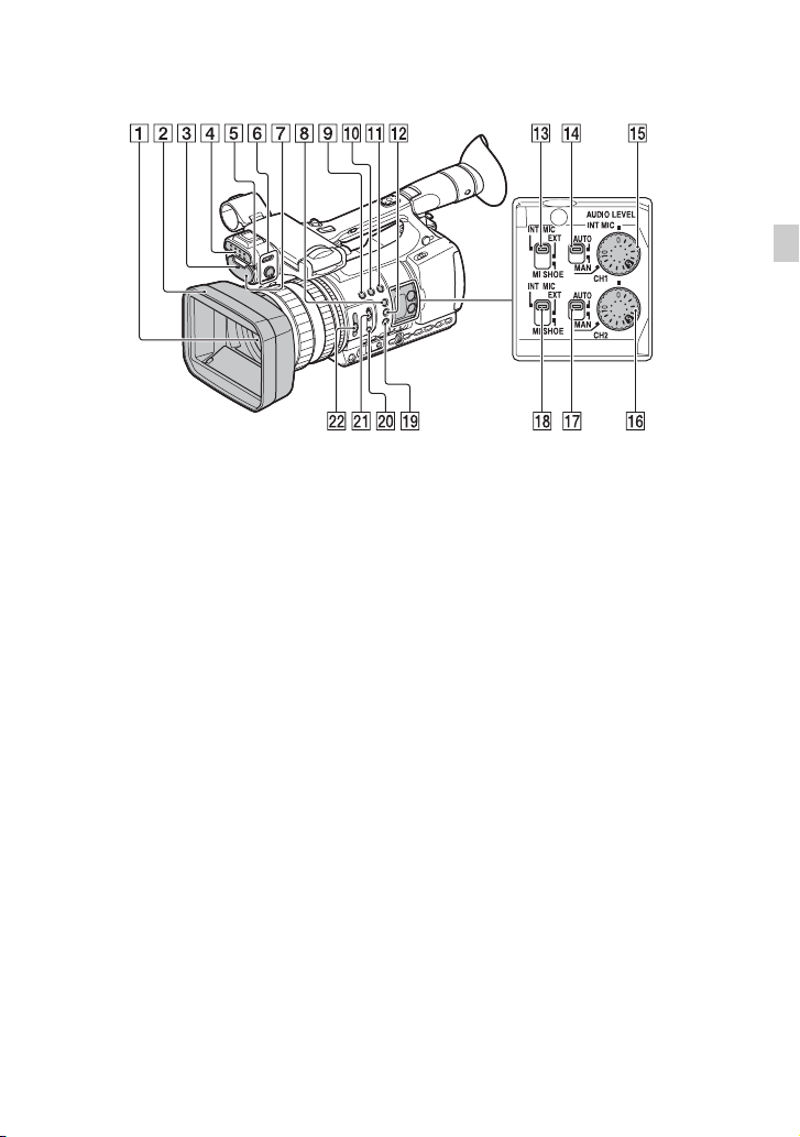
Identifying Parts and Controls
A Lens (G lens)
B Lens cover with hood (p. 22)
C Front recording lamp (p. 106)
Flashes when remaining capacity of the
memory card or battery becomes low.
D Video light (p. 49)
E Remote control sensor (p. 14)
F LIGHT switch/dimmer dial (p. 49)
G Internal microphone
H ASSIGN1/PEAKING button (p. 99)
I ASSIGN3/IRIS PUSH AUTO button
(p. 39)
J ASSIGN4/LAST SCENE button*
(p. 53)
K ASSIGN5/ZEBRA button (p. 99)
L ASSIGN2/HISTOGRAM button*
(p. 99)
M CH1 (INT MIC/EXT/MI SHOE) switch
(p. 46)
N AUTO/MAN (CH1) switch (p. 46)
O AUDIO LEVEL (CH1) dial (p. 46)
P AUDIO LEVEL (CH2) dial (p. 46)
Q AUTO/MAN (CH2) switch (p. 46)
R CH2 (INT MIC/EXT/MI SHOE) switch
(p. 46)
S S&Q button (p. 52)
T PUSH AUTO/FOCUS HOLD button
(p. 35)
U FOCUS switch (p. 35)
V ND FILTER switch (p. 41)
* The ASSIGN4/LAST SCENE button and
ASSIGN2/HISTOGRAM button each have a
notch (protrusion) to aid finger placement
during operation.
Continued ,
9
Page 10
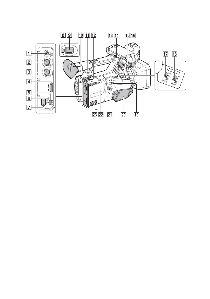
Identifying Parts and Controls (Continued)
A AUDIO OUT jack (p. 60)
B VIDEO OUT jack (p. 60)
C SDI OUT jack (p. 60)
D HDMI OUT jack (p. 60)
E Multi/Micro USB jack (p. 60)
F CHG (charging) lamp (p. 20)
G DC IN jack (p. 19)
H Eye sensor (p. 27)
I Viewfinder (p. 27)
J Large eyecup (p. 27)
K Diopter adjustment dial (p. 27)
L Cable clamper
M Handle zoom lever (p. 34)
N Handle record button (p. 31)
O INPUT2 jack (p. 46)
P INPUT1 jack (p. 46)
Q INPUT2 (LINE/MIC/MIC+48V) switch
(p. 46)
R INPUT1 (LINE/MIC/MIC+48V) switch
(p. 46)
S REMOTE jack (p. 49)
The REMOTE jack connects to a video
deck or other devices used to control
playback.
10
T Grip belt
U START/STOP button (p. 31)
V Multi-selector (p. 44)
W Air vents
May become warm due to heat
dissipation.
Do not block the vents when shooting.
About the cable clamper
Attaching the power cord, HDMI cable, and
other cables, inserted in the corresponding
connectors, in the cable clamper helps
prevent the cords from being disconnected.
However, not all HDMI cables are
supported.
Page 11
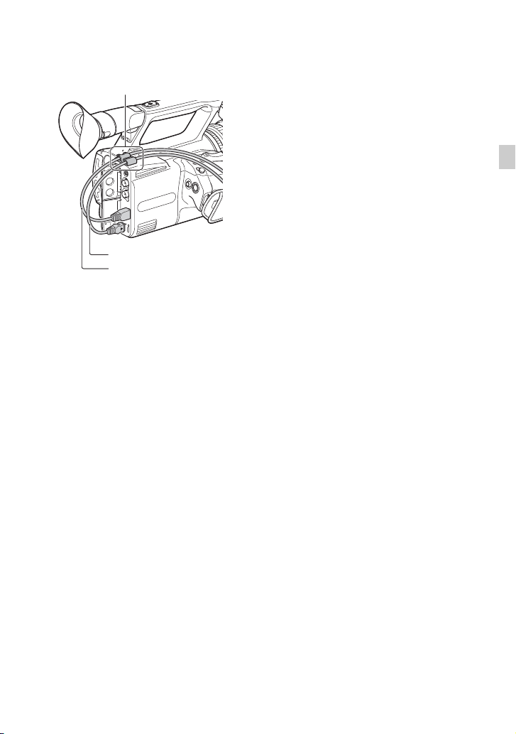
Cable clamper
Power cord
HDMI cable
Identifying Parts and Controls
Continued ,
11
Page 12
Identifying Parts and Controls (Continued)
A Hook for shoulder strap
B Focus ring (p. 35)
C Lens cover lever (p. 23)
D Zoom ring (p. 34)
E Iris ring (p. 39)
F GAIN button (p. 40)
G WHT BAL button* (p. 42)
H SHUTTER button (p. 40)
I AUTO/MANUAL switch (p. 39)
J i (headphones) jack
Use headphones that have a stereo mini
jack.
K POWER lamp
L BATT RELEASE button (p. 20)
M ON/STANDBY switch (p. 25)
N Battery pack (p. 19)
O Memory card slot B/Select button/
Access lamp (p. 29)
P Memory card slot A/Select button/
Access lamp (p. 29)
Q WB SET button (p. 43)
R B/A/PRESET switch (p. 42)
S L/M/H switch (p. 40)
T IRIS button* (p. 39)
* The IRIS button and WHT BAL button each
have a notch (protrusion) to aid finger
placement during operation.
To attach the shoulder strap (sold
separately)
Attach to the shoulder strap hook as
illustrated.
12
Page 13
Identifying Parts and Controls
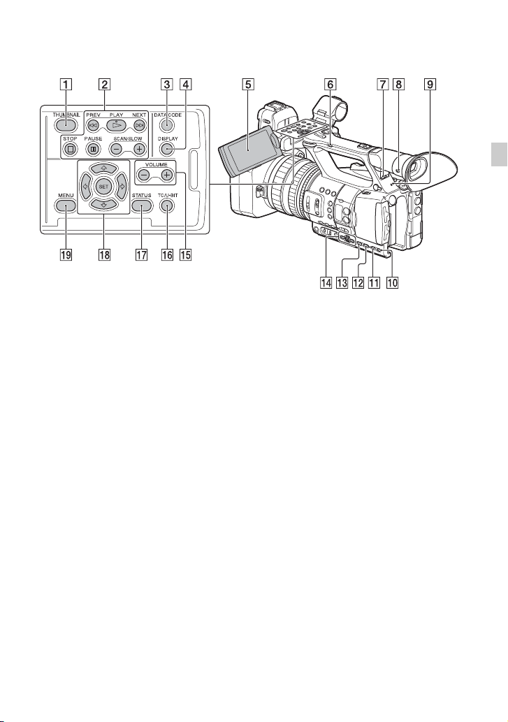
A THUMBNAIL button (p. 55)
B Playback buttons (PREV, PLAY*,
NEXT, STOP, PAUSE, SCAN/SLOW)
C DATA CODE button (p. 58)
D DISPLAY button (p. 58)
E LCD screen (p. 27)
F Handle zoom switch (p. 34)
G HEADPHONE MONITOR switch
(p. 48)
H VF/LCD PANEL button (p. 28)
I Rear recording lamp (p. 106)
Flashes when remaining capacity of the
memory card or battery becomes low.
J STATUS button (p. 59)
K P PROFILE button (p. 51)
L DISPLAY button (p. 58)
M MENU button** (p. 85)
N SEL/SET dial, B/b buttons (p. 85)
O VOLUME buttons* (p. 56)
P TC/U-BIT button
Switches the LCD screen between time
code and user bits display.
Q STATUS button (p. 59)
R V/v/B/b/SET buttons (p. 85)
S MENU button (p. 85)
* The VOLUME “+” button and PLAY button
each have a notch (protrusion) to aid finger
placement during operation.
**The MENU button has a notch bar (protrusion)
to aid finger placement during operation.
Continued ,
13
Page 14
Identifying Parts and Controls (Continued)
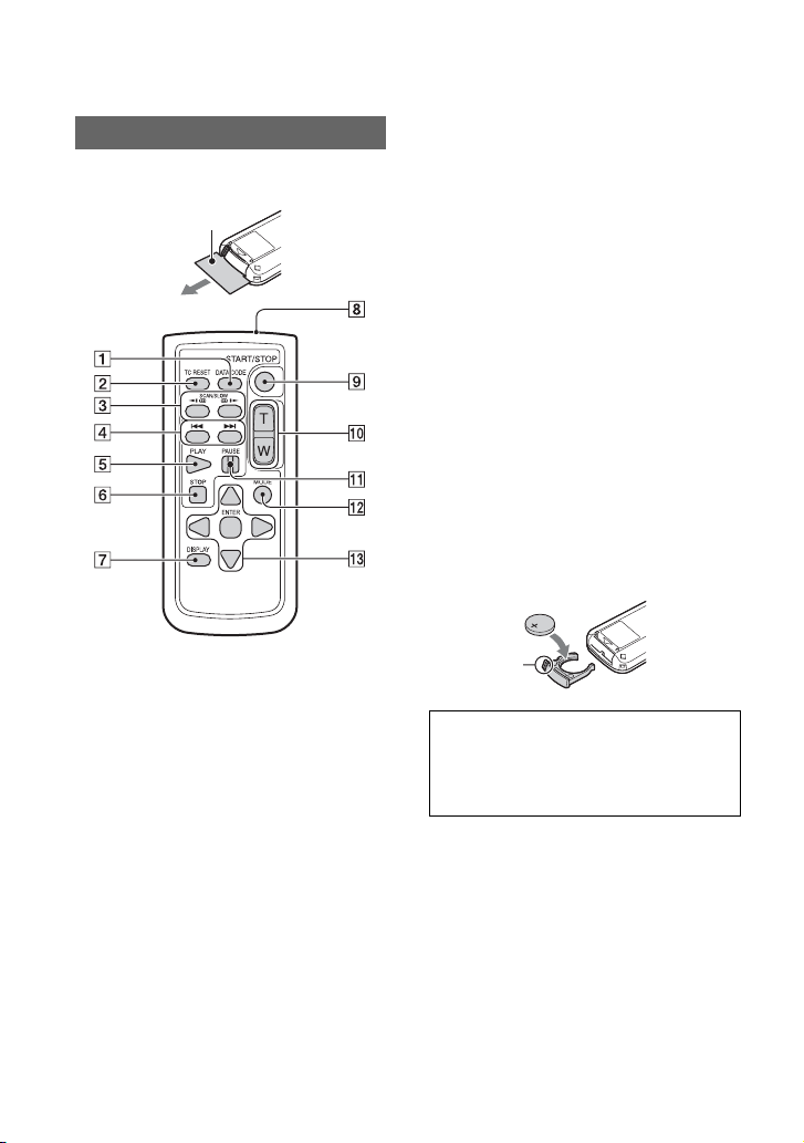
Wireless Remote Commander
Remove the insulation sheet before using
the Wireless Remote Commander.
Insulation sheet
A DATA CODE button (p. 58)
B TC RESET button (p. 52)
C SCAN/SLOW buttons (p. 55)
D . > (PREV/NEXT) buttons
(p. 55)
E PLAY button (p. 55)
F STOP button (p. 55)
G DISPLAY button (p. 58)
H Transmitter
I START/STOP button (p. 31)
J Power zoom lever
K PAUSE button (p. 55)
L MODE button
M b/B/v/V/ENTER buttons
b Notes
• Aim the Wireless Remote Commander towards
the remote sensor to operate your camcorder.
• Point the remote sensor away from strong light
sources such as direct sunlight or overhead
lighting. Otherwise, the Wireless Remote
Commander may not function properly.
• When you are operating with the Wireless
Remote Commander supplied with your
camcorder, your video device may also operate.
In that case, select a commander mode other
than DVD2 for your video device, or cover the
sensor of your video device with black paper.
To change the battery of the Wireless
Remote Commander
1 While pressing on the tab, inset your
fingernail into the slit to pull out the
battery case.
2 Place a new battery with the + side
facing up.
3 Insert the battery case until it clicks into
place.
Tab
WARNING
Battery may explode if mistreated. Do not
recharge, disassemble or dispose of in
fire.
• When the lithium battery becomes weak, the
operating distance of the Wireless Remote
Commander may shorten, or the Wireless
Remote Commander may not function properly.
In this case, replace the battery with a Sony
CR2025 lithium battery. Use of another battery
may present a risk of fire or explosion.
14
Page 15
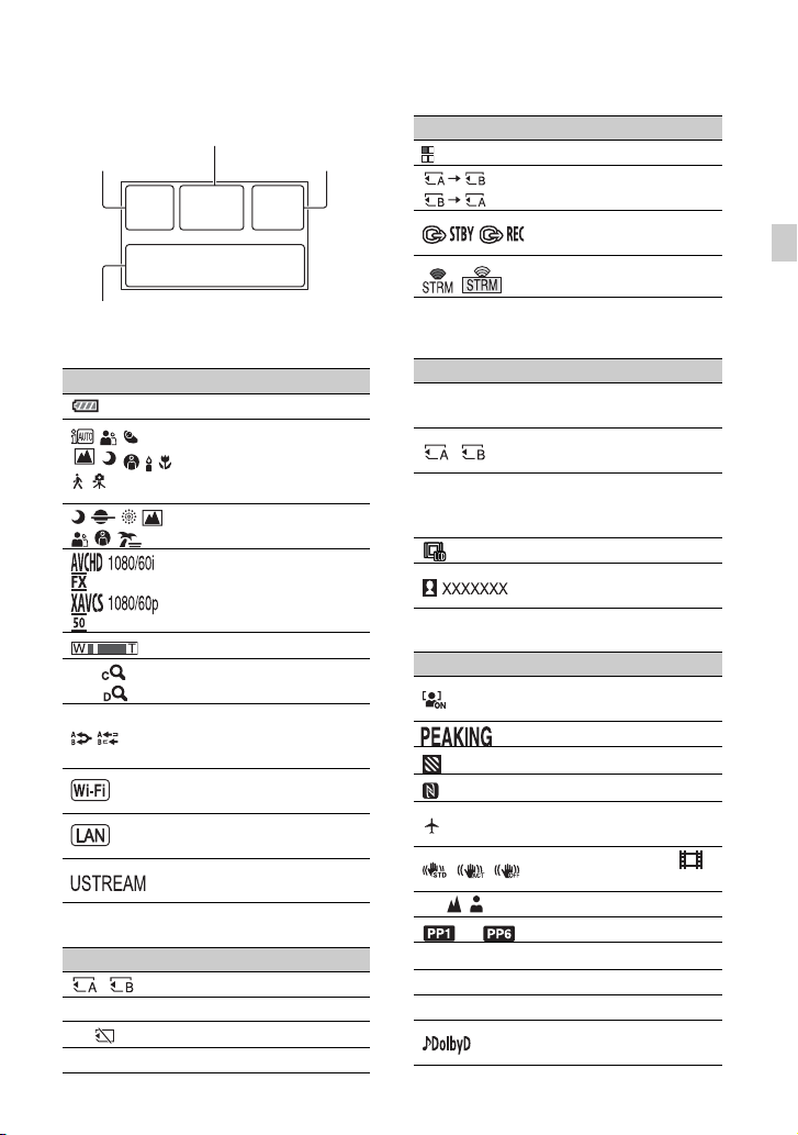
Screen Indicators
Upper left Upper right
Bottom
Center
Upper left
Indicator Meaning
100% Remaining battery
INTELLIGENT AUTO
.
(face detection/scene
detection/camera-shake
detection) (p. 50)
SCENE SELECTION
(p. 50)
Recording format (p. 38)
Optical zoom (p. 89)
Z99 ×1.2
Z99 ×2.3
Clear image zoom (p. 89)
Digital zoom (p. 89)
Simultaneous recording
(p. 33)
Relay recording (p. 32)
Wireless LAN connection
(p. 68)
Wired LAN connection
(p. 72)
USTREAM streaming
(p. 75)
Center
Indicator Meaning
Memory card (p. 29)
REC STBY Recording standby (p. 31)
E Warning (p. 121)
N Playback indicator (p. 55)
Indicator Meaning
Processing
Relay recording (p. 32)
SDI/HDMI REC
CONTROL (p. 96)
Streaming (p. 73, 75)
Upper right
Indicator Meaning
0min
00:00:00:00
Estimated remaining
recording time
Recording/playback
media
Time code
(hour:minute:second:
frame) (p. 51)
VF/LCD PANEL (p. 28)
USTREAM audience
(p. 75)
Bottom
Indicator Meaning
Face detection [ON]
(p. 36)
Peaking (p. 99)
Zebra (p. 99)
NFC active (p. 66)
Airplane mode [ON]
(p. 104)
9 Manual focus (p. 35)
to Picture profile (p. 51)
F5.6 Iris (p. 39)
9dB Gain (p. 40)
100 180° Shutter speed (p. 40)
Image stabilization (
STEADYSHOT) (p. 89)
AVCHD audio format
(p. 97)
Continued ,
Identifying Parts and Controls
15
Page 16
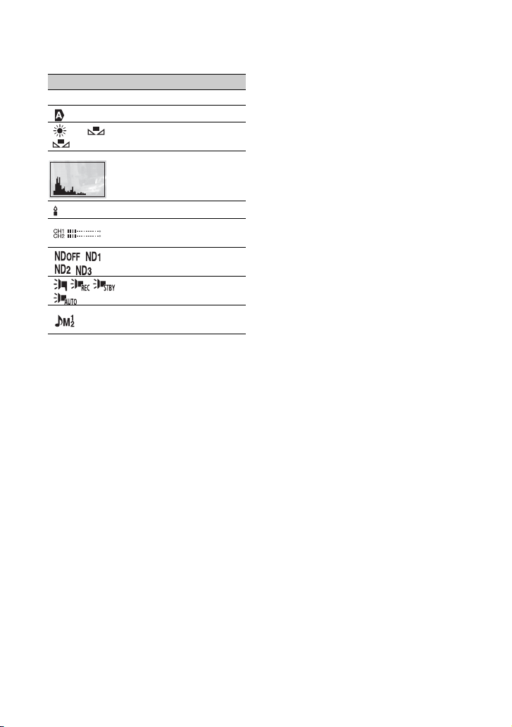
Screen Indicators (Continued)
Indicator Meaning
-2.0EV AE shift (p. 88)
Auto setting (p. 39)
n A
B
z Tip
• Indicators may look different or appear at
different positions.
Data during recording
The date, time, and recording conditions are
recorded automatically.
You can check the data by pressing the
DATA CODE button during playback.
White balance (p. 42)
Histogram (p. 99)
Auto slow shutter (p. 91)
Audio level display
(p. 101)
ND filter (p. 41)
Multi Interface Shoe
video light (p. 91)
Manual volume
adjustment (p. 48)
16
Page 17
Getting Started
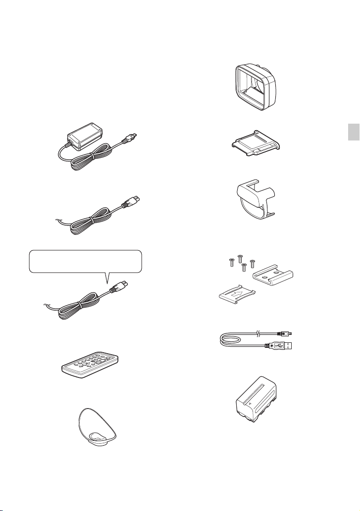
Step 1: Checking supplied accessories
Make sure that you have following items
supplied with your camcorder. If, for any
reason, there is something missing, contact
your Sony dealer.
The number in the parentheses indicates the
number of that item supplied.
AC Adaptor (AC-L100 C) (p. 19)
Power cord (mains lead) (p. 19)
IS1293 power cord for India.
Not supplied in some countries.
RMT-845 Wireless Remote Commander
(p. 14)
Lens cover with hood (p. 22)
Shoe cap
Getting Started
Video light diffuser (p. 23)
Accessory shoe kit (Accessory shoe (1),
Accessory shoe plate (1), screws (4))
(p. 24)
USB cable
A button-type lithium battery is already installed.
Large eyecup (p. 27)
Rechargeable battery pack (NP-F770)
Continued ,
17
Page 18

Step 1: Checking supplied accessories (Continued)
Battery charger (BC-L1)
CD-ROM “Manuals for Solid-State Memory
Camcorder”
Operating Guide (2)
Software Downloads
When the unit is used with a PC
connection, download any device drivers,
plug-ins, and application software you
require from the following websites.
You can work with recorded video on a
computer, for example, combining relayrecorded movies, using the “Catalyst
Browse” application software. For details,
see the supplied brochure.
Sony Professional products website:
U.S.A. http://pro.sony.com
Canada http://www.sonybiz.ca
Latin America
http://sonypro-latin.com
Europe, Middle East, and Africa
http://www.pro.sony.eu
Japan http://www.sonybsc.com
Asia Pacific
http://pro.sony-asia.com
Korea http://bp.sony.co.kr
China http://pro.sony.com.cn
Although the data regarding recorded
materials are stored over multiple files and
folders, you can easily handle the clips
without considering its data and directory
structure, by using the dedicated application
software.
18
Page 19
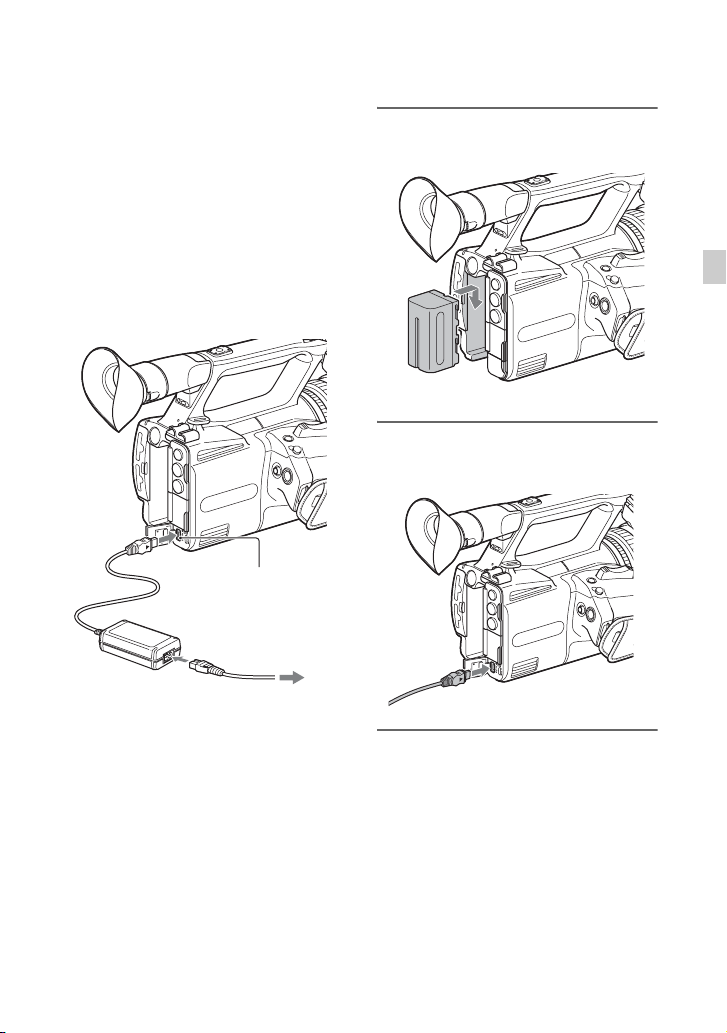
Step 2: Charging the battery pack
You can charge the “InfoLITHIUM”
battery pack (L series) (supplied or
sold separately) with the supplied
AC Adaptor.
b Notes
• You can use an NPF970 large capacity battery
pack (sold separately) with your camcorder.
• Do not place the battery pack anywhere hot,
such as in direct sunlight or near naked flames.
• Use the supplied AC Adaptor when powering
the camcorder from a power outlet.
DC plug
AC Adaptor
DC IN jack
Power cord
To power outlet
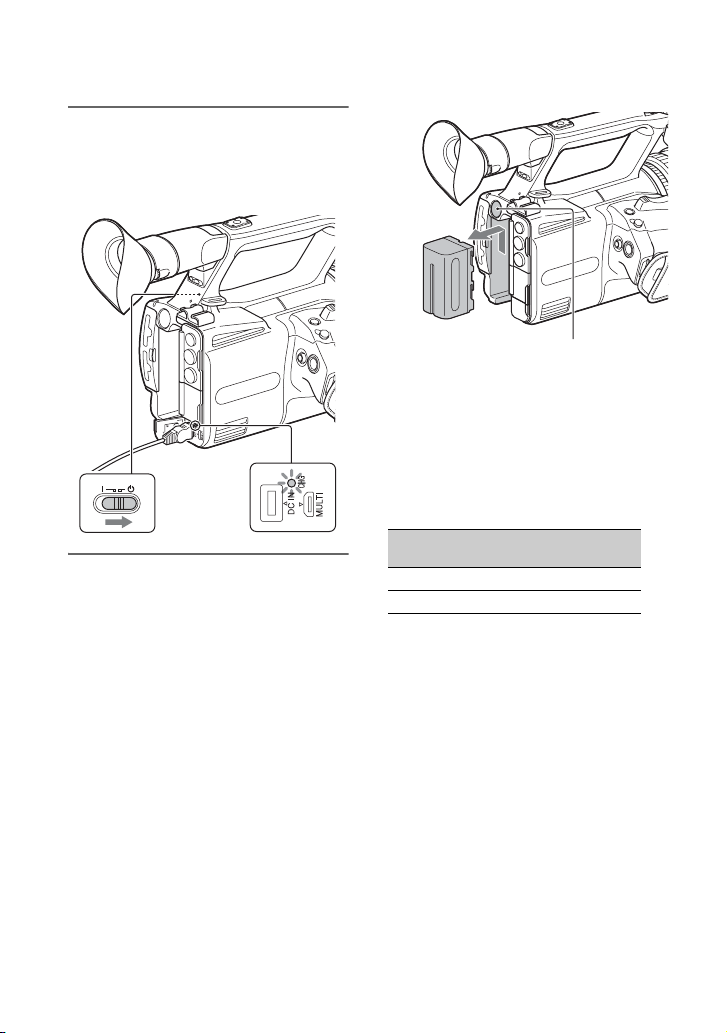
1 Push the battery in and slide it
down into position.
Getting Started
2 Connect the DC plug to the DC IN
jack of the camcorder.
3 Connect the power cord (mains
lead) to the AC Adaptor and the
wall outlet (wall socket).
Continued ,
19
Page 20
Step 2: Charging the battery pack (Continued)
4 Set the ON/STANDBY switch to
STANDBY (1).
The CHG lamp lights up and charging
starts.
To store the battery pack
If the battery pack is not in use for a while,
run down the battery and store it (p. 134).
Charging time
Approximate time (minutes) required when
you charge a fully discharged battery pack.
Battery pack
When charging ends
The CHG lamp turns off when the battery is
fully charged.
Disconnect the AC Adaptor from the DC
IN jack.
z Tip
• You can check the remaining battery life with
the status check function (p. 59).
To remove the battery pack
Set the ON/STANDBY switch to
STANDBY (1). Press and hold the BATT
RELEASE button, and slide the battery up
and out.
NP-F770 370
NP-F970 (sold separately) 485
On the battery pack
• Always set the ON/STANDBY switch to
STANDBY (1) before changing the battery
pack.
• The CHG lamp flashes during charging, or the
Battery Info will not be correctly displayed
under the following conditions.
– The battery pack is not attached correctly.
– The battery pack is damaged.
– The battery pack is worn-out.
Using a power outlet
You can use the AC Adaptor to obtain the
AC power. While you are using the AC
Adaptor, the battery pack will not lose its
charge even when it is attached to your
camcorder.
BATT RELEASE button
Full charge
time
20
Page 21
Perform the procedure up to step 3 of “Step
2: Charging the battery pack” (p. 19).
b Notes
• The video light will not turn on when using the
AC-L100 C AC Adaptor (supplied). Use a
separate battery pack (supplied or sold
separately) to power the video light (p. 49).
• You can power the video light while supplying
power by using a DK-415 battery eliminator
connecting cable adaptor (1-782-361-xx) and a
AC-VL1 AC Adaptor/Charger (1-487-539-xx).
For details about purchasing the DK-415 battery
eliminator connecting cable adaptor and ACVL1 AC Adaptor/Charger, contact your Sony
dealer.
On the AC Adaptor
• Do not short-circuit the DC plug of the AC
Adaptor or battery terminal with any metallic
objects. This may cause a malfunction.
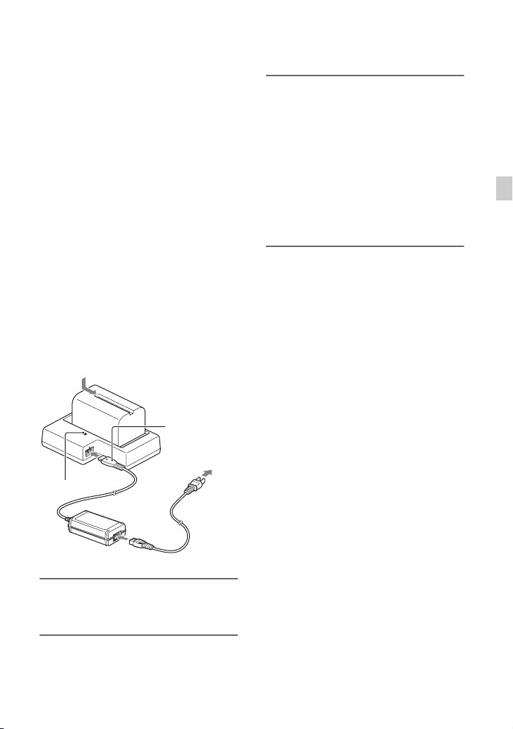
To charge the battery pack using the
supplied battery charger (BC-L1)
DC plug
To power outlet
CHG lamp
3 Push the battery in and slide it in
the direction of the arrow in the
diagram.
The CHG lamp lights up and charging
starts.
When charging ends, the CHG lamp
turns off.
Slide the battery pack out in the
opposite direction and remove it from
the battery charger.
b Note
• Even if the CHG lamp is not lit, the battery
charger is not disconnected from the AC power
source (mains) as long as it is connected to the
wall outlet (wall socket).
Getting Started
Power cord
1 Connect the DC plug to the DC IN
jack of the battery charger.
2 Connect the power cord (mains
lead) to the AC Adaptor and the
wall outlet (wall socket).
21
Page 22
Step 3: Attaching the microphone, lens cover with hood, and video light diffuser
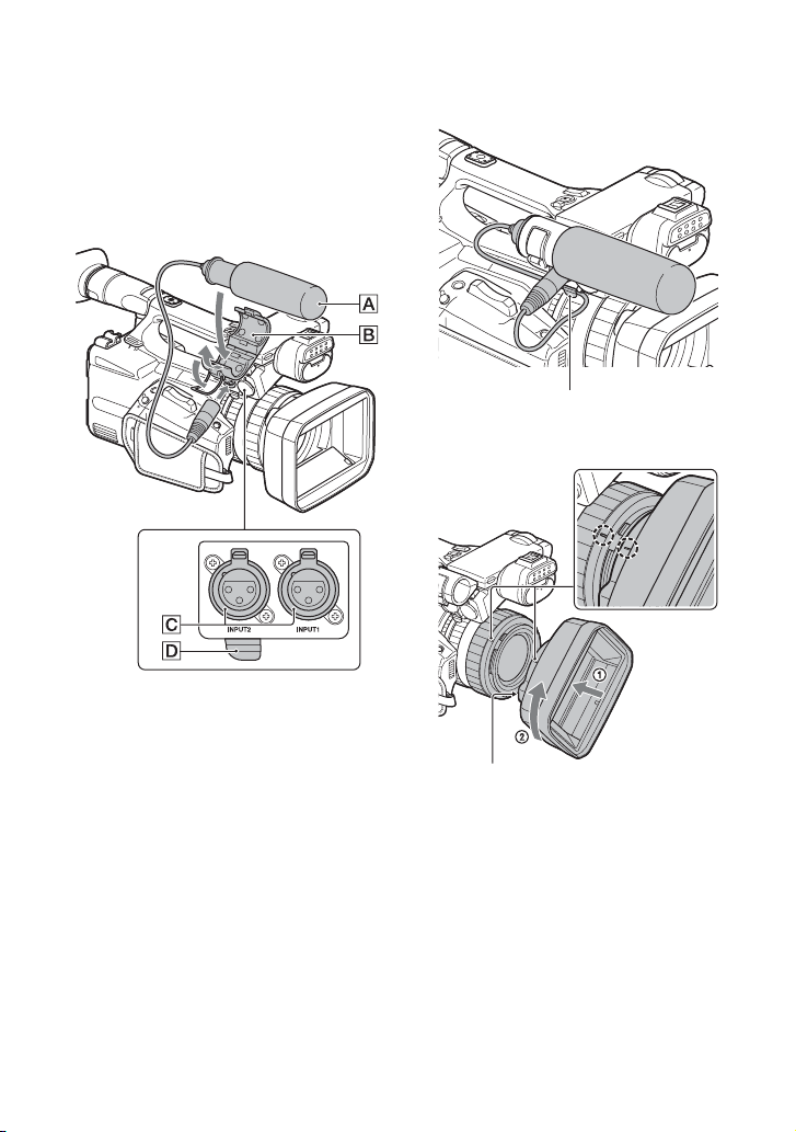
Attaching the microphone (sold
separately)
Use the following procedure to attach an
external microphone (sold separately) to
record audio.
Put the cable in the outer cable holder.
Attaching the lens cover with hood
1 Place the microphone A into the
microphone holder B.
2 Connect the plug of the microphone to
the INPUT1 jack or INPUT2 jack C.
3 Place the microphone cable into the
cable holder D.
22
PUSH (lens hood removal) button
Align the mark on the lens hood to the mark
on the camcorder, and turn the lens hood in
the direction of the arrow
locked.
2 until it is
Removing the lens cover with hood
Press and hold the PUSH (lens hood
removal) button, and turn the lens hood in
the opposite direction to the arrow.
z Tip
• If you attach or remove a 72 mm PL filter or
MC protector, remove the lens hood.
Page 23
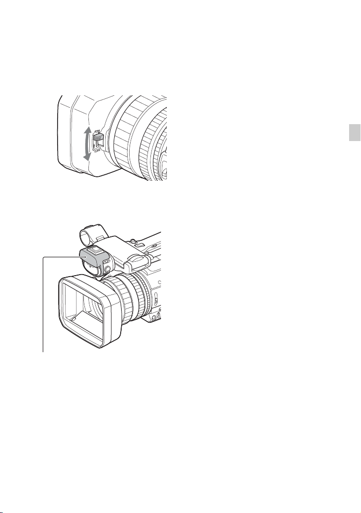
Opening/closing the lens cover
To open the lens cover, move the lens cover
lever to the OPEN position. To close it,
move it to the CLOSE position.
Attaching the video light diffuser
The video light diffuser reduces the glare
and softens the light.
Getting Started
Video light diffuser
23
Page 24
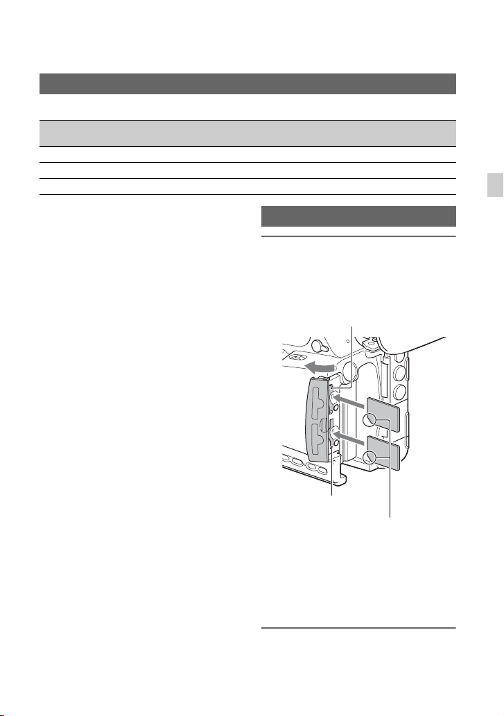
Step 4: Attaching the accessory shoe
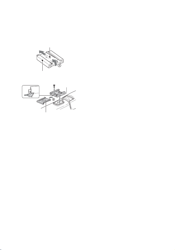
To mount the accessory shoe
Mount the accessory shoe on the accessory
shoe mount as illustrated.
Accessory shoe plate
Accessory shoe
Accessory
shoe
Accessory shoe plate
1 Lift the edge of the accessory shoe plate
and pull it in the direction opposite to
that of the arrow on the accessory shoe
plate and remove it from the accessory
shoe.
2 Place the accessory shoe as its
protrusions matches recesses of the
accessory shoe mount, then fix it to the
mount with four screws.
3 Insert the accessory shoe plate in the
direction of the arrow on the plate
surface until the end of the plate
engages the end of the shoe.
To remove the accessory shoe
Remove the shoe plate in the same way as
step 1 of “To mount the accessory shoe.”
Loosen the 4 screws and remove the
accessory shoe from the accessory shoe
mount.
24
Page 25
Step 5: Turning on the camcorder and setting the date and time
Turning on the camcorder Setting the date and time
Set the date and time when you use your
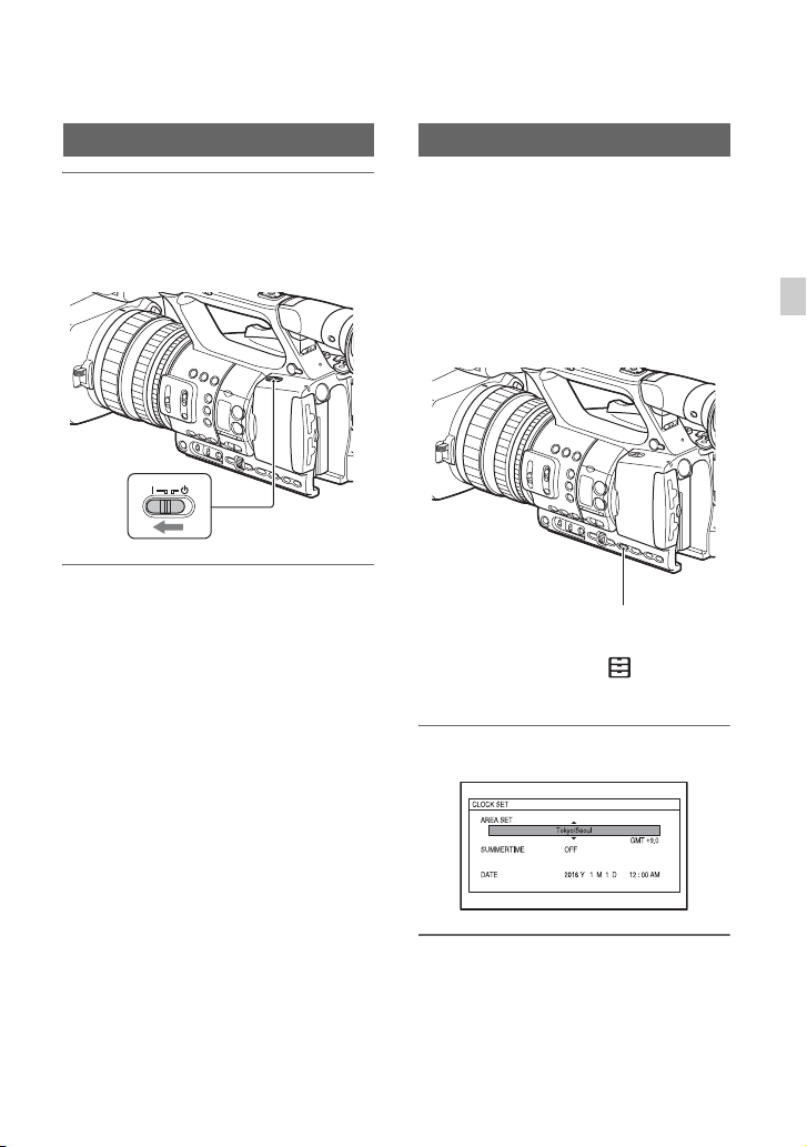
Set the ON/STANDBY switch to ON
(❙).
When you use your camcorder for the first
time, the [CLOCK SET] screen appears.
camcorder for the first time.
z Tip
• If you do not use your camcorder for about 3
months, the built-in rechargeable battery gets
discharged and the date and time settings may
be cleared from the memory. In that case,
charge the rechargeable battery and then set the
date and time again (p. 137).
Getting Started
To turn off the power
Set the ON/STANDBY switch to
STANDBY (1).
b Note
• If a warning message is displayed, follow the
instructions.
MENU button
To set the date and time again, press the
MENU button, and select (OTHERS)
t [CLOCK SET].
1 Set the area.
2 Set [SUMMERTIME], [Y], [M], [D],
hour, and minute.
Continued ,
25
Page 26

Step 5: Turning on the camcorder and setting the date and time
(Continued)
The clock starts.
• Set [SUMMERTIME] to [ON] to move the
time forward 1 hour.
• You can set any year up to the year 2037.
• Midnight is indicated as 12:00 AM, and
noon as 12:00 PM.
z Tip
• The date and time are automatically recorded on
the selected memory card, and can be displayed
during playback (p. 101).
26
Page 27
Step 6: Adjusting the LCD screen and viewfinder
Using the LCD screen
The LCD screen can be rotated in the range
as illustrated below, allowing a person other
than the camera operator to see the image.
1 Open 180°
2 90° (max.)
2 180°
(max.)
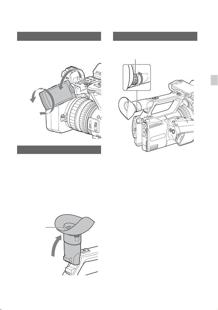
Using the viewfinder
When the LCD screen and viewfinder
switching is set to AUTO (p. 28), the
display switches to viewfinder display
automatically whenever your eye is near the
eye sensor on the side of the viewfinder.
When you move your eye away from the
viewfinder, the display switches back to the
LCD screen.
You can adjust the angle of the viewfinder
to suit your shooting style.
Adjusting the viewfinder diopter
Diopter adjustment dial
Move it until the picture becomes clear.
Getting Started
When the picture in the viewfinder is
hard to see
If you cannot see the picture in the
viewfinder clearly under bright
circumstances, use the supplied large
eyecup. To attach the large eyecup, stretch
it slightly and fit it over the groove of the
eyecup attached to the camcorder. You can
attach the large eyecup facing either the
right or left side.
Eye sensor
b Note
The LCD screen and the viewfinder do not
operate at the same time.
Continued ,
27
Page 28
Step 6: Adjusting the LCD screen and viewfinder (Continued)
Large eyecup
(supplied)
b Note
• Do not remove the eyecup pre-attached to the
camcorder.
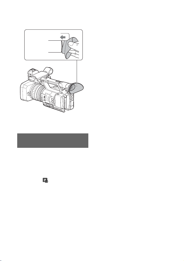
Switching between LCD screen display and viewfinder display
Press the VF/LCD PANEL button.
The display changes with each press of the
button.
• To use only the LCD screen, press the
button until “VF/LCD PANEL: LCD
PANEL” is displayed on the LCD screen.
In this mode, appears on the LCD
screen.
• To switch between the LCD screen and
the viewfinder automatically, press the
button until “VF/LCD PANEL: AUTO” is
displayed on the LCD screen.
When AUTO is selected, the display
switches to viewfinder display
automatically whenever your eye is near
the eye sensor on the side of the
viewfinder. When you move your eye
away from the viewfinder, the display
switches back to the LCD screen.
z Tip
• The eye sensor will be activated if the eye
sensor is blocked, even if you are not looking
into the viewfinder.
28
Page 29
Step 7: Inserting a memory card
Supported memory cards
Normal recording
SD SDHC
SDXC memory
cards
AVCHD Yes*1 Yes*1 Yes*1 Yes*4
2
XAVC S HD – – Yes*
3
DV Yes*
Yes: Supported
–: Not supported
*1Class 4 or higher supported
2
*
Class 10 supported
3
*
Class 6 or higher supported
4
PRO Duo (Mark 2), PRO-HG Duo supported
*
5
*
PRO-HG Duo supported
Yes*3 Yes*3 Yes*5
Inserting a memory card
Open the cover, and insert the
memory card with the notched
corner in the direction as illustrated
until it clicks into place.
–
Slow & Quick Motion
SDHC and SDXC memory cards (Class 10)
are supported when the file format is
AVCHD.
b Notes
• Operation with all memory cards is not assured.
• See page 125 for the recording time of memory
cards.
• Movies recorded on SDXC memory cards can
be imported to or played back on other
equipment, such as a computer or A/V device,
by connecting the camcorder to the equipment
with the USB cable. However, the equipment
must support the exFAT file system used for
SDXC memory cards. Confirm in advance that
the connecting equipment is supporting the
exFAT file system. If you connect equipment
not supporting the exFAT file system and the
format screen appears, do not perform the
format. All the data recorded will be lost.
Memory card slot B
Note the direction of the notched corner.
• If you insert a memory card into the slot in the
wrong direction, the memory card, the memory
card slot, or image data may be damaged.
• Memory card slot A accepts both “Memory
Stick PRO Duo” and SD cards. Memory card
slot B accepts SD cards only.
“Memory Stick”
media
Memory card slot A
Getting Started
To eject a memory card
Lightly push the memory card once.
Continued ,
29
Page 30
Step 7: Inserting a memory card (Continued)
b Notes
• If “The image database file is corrupted. The
media must be restored to use again.” appears,
format the memory card (p. 83).
• When inserting or ejecting the memory card, be
careful of the memory card popping out and
dropping.
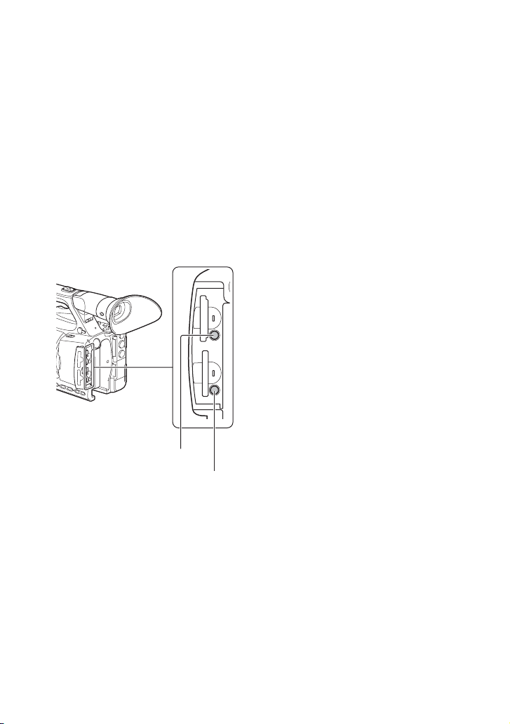
Selecting the memory card slot to be
used for recording
Press the memory card slot A or slot B
button to select the inserted memory card
for recording. You can confirm the selected
slot on the screen.
SD ONLY
Memory card slot A button
Memory card slot B button
b Notes
• You can only select a slot that already has a
memory card inserted.
• When recording to a memory card, you cannot
switch the slot even if you press the memory
card slot A or slot B button.
z Tips
• When only one slot has a memory card inserted,
the slot that has the memory card is selected
automatically.
• When the memory card becomes full during
recording, the camcorder automatically switches
to the other slot if a memory card is inserted
(relay recording, p. 32).
If a repair memory card prompt screen
appears
There may have been a problem recording
to the memory card during the most-recent
recording. Select [OK] to repair the card to
the extent possible. Select [Cancel] to
continue without repairing.
30
Page 31

Recording
Recording
Recording
Your camcorder records movies on memory cards. The factory setting for recording is
AVCHD.
Check that the memory cards are inserted correctly, and press the START/STOP button
(handle record button) to start recording.
[STBY] t [REC]
The recording lamps light up during recording.
To stop recording, press the START/STOP button (handle record button) again.
b Notes
• When the access lamp is lit or flashing in red, your camcorder is reading or writing data. Do not shake or
apply strong force to your camcorder, do not turn the power off, and do not remove the memory card,
battery pack or the AC Adaptor. The image data may be destroyed.
• If a movie file size exceeds 2 GB while recording in DV or AVCHD format, the camcorder automatically
divides the file and creates a new one.
• When recording in XAVC S HD, recording stops automatically when the recorded file reaches 13 hours
duration.
• The menu settings, the picture profile settings, and the settings made by the AUTO/MANUAL switch are
stored when you slide the ON/STANDBY switch to STANDBY (1). The access lamp is lit while the
settings are being saved. If you remove the battery pack or the AC Adaptor before turning off the power,
the settings may return to the default settings.
z Tips
• When recording with a setting other than DV, the aspect ratio is fixed to 16:9. When recording in DV
mode, you can switch the aspect ratio to 4:3 ([ WIDE REC], p. 93).
• For details about changing the screen display during recording, see page 58.
• For details about screen display during recording, see page 15.
• The recording lamp can be set to stay off ([REC LAMP[F]], [REC LAMP[R]], p. 106).
• See page 125 about the recording time of movies.
Recording
Continued ,
31
Page 32

Recording (Continued)
Continuous recording on the memory cards (Relay Rec)
Insert memory cards each in both slots A and B so the camcorder switches memory card A (or
B) just before the remaining space on the other one runs out, and continues recording on the
next memory card automatically.
Make the following setting before recording.
Set (REC/OUT SET) t [REC SET] t [SIMUL/RELAY REC] t [RELAY REC].
Exchange the recordable memory card
Low remaining
capacity
REC start
REC end
Low remaining capacity
b Notes
• Do not eject the memory card that is currently being used for recording. When replacing a memory card
while recording, replace only the one in the slot whose access lamp is off.
• When recording, you cannot switch the slot even if you press the memory card slot A or slot B button.
• When the remaining recording time of the memory card being used is less than 1 minute and the other slot
has a recordable memory card inserted, [ ] or [ ] appears on the camcorder screen.
The indicator turns off when the memory card is switched.
• If you start recording on a memory card with the remaining recording time of less than 1 minute, the
camcorder may not be able to relay-record. To relay-record without failing, make sure that the memory
card has more than 1 minute when you start recording.
• Seamless playback of relay-recorded movies with this camcorder is not possible.
• You can combine relay-recorded movies using application software (p. 18).
• The maximum recording time using relay recording is about 13 hours. Recording stops automatically
when the maximum recording time elapses.
REC: Recording
32
Page 33

Recording movies using both memory card A and B (Simul Rec)
You can record movies on both memory card A and memory card B simultaneously.
Set (REC/OUT SET) t [REC SET] t [SIMUL/RELAY REC] t [SIMULTANEOUS
REC].
Changing the START/STOP button/handle record button setting
You can start and stop recording on different memory cards by using the START/STOP
button and the handle record button.
In the default setting, movies are recorded on both the memory card A and B at the same time
when either record button is pressed.
• REC BUTTON:
• HANDLE REC BUTTON:
To change the setting
Select (REC/OUT SET) t [REC SET] t [REC BUTTON SETTING].
REC BUTTON SETTING setting Button and memory card
REC BUTTON:
HANDLE REC BUTTON:
REC BUTTON:
HANDLE REC BUTTON:
REC BUTTON:
HANDLE REC BUTTON:
Recording on both the memory card A and the
memory card B starts and stops at the same time when
either record button is pressed.
Recording on the memory card A starts and stops
when the START/STOP button is pressed, and on the
memory card B when the handle record button is
pressed.
Recording on the memory card B starts and stops
when the START/STOP button is pressed, and on the
memory card A when the handle record button is
pressed.
Recording
Continued ,
33
Page 34

Recording (Continued)
Adjusting the zoom
Adjusting the zoom with the power
zoom lever
Press the zoom lever D slightly to zoom
slowly, and press it further to zoom more
quickly.
z Tips
• When focusing, the minimum distance required
between the camcorder and the subject is about
1 cm (about 13/32 in.) for wide angle and about
80 cm (about 31 1/2 in.) for telephoto.
• The focus may not be adjusted at certain zoom
positions if the subject is within 80 cm (about 31
1/2 in.) from your camcorder.
• Be sure to keep your finger on the power zoom
lever D. If you remove your finger, the
operation sound of the power zoom lever D
may also be recorded.
• You can select the type of zoom operation for
the zoom lever ([ZOOM TYPE], page 89).
• You can increase the zoom speed of the power
zoom lever D ([SPEED ZOOM], page 89).
z Tips
• When set to VAR, you can zoom in or out at
variable speed.
• When set to FIX, you can zoom in or out at
fixed speed (set in [HANDLE ZOOM],
page 89).
2 Press the handle zoom lever A to zoom
in or out.
b Notes
• You cannot use the handle zoom when the
handle zoom switch B is set to OFF.
• You cannot change the zoom speed of the power
zoom lever D with the handle zoom switch B.
z Tip
• You can increase the zoom speed of the handle
zoom lever A ([SPEED ZOOM], page 89).
Adjusting the zoom with the zoom
ring
You can zoom at the desired speed by
turning the zoom ring C. Fine adjustment
is also possible.
b Note
• Turn the zoom ring C at a moderate speed. If
you turn it too fast, the zoom may lag behind the
zoom ring rotation, or the operation sound of the
zoom may also be recorded.
Adjusting the zoom with the handle
zoom
1 Set the handle zoom switch B to VAR
or FIX.
34
Page 35

Adjusting the focus
You can adjust the focus manually for
different recording conditions.
1 During recording or standby, set
the FOCUS switch B to MAN.
9 appears.
2 Turn the focus ring A to adjust
the focus.
9 changes to when the focus
cannot be adjusted any farther, and
changes to when the focus cannot be
adjusted any closer.
To adjust automatically
Set the FOCUS switch B to AUTO.
9 disappears and the automatic focus
adjustment is restored.
z Tips
• The focal length information (the distance at
which the subject is in focus; for when it is dark
and hard to adjust the focus) appears for about 3
seconds in the following cases.
– When you set the FOCUS switch B to MAN
and 9 appears.
– When you rotate the focus ring A while 9
is displayed.
• You can switch the focal length information
between meters and feet ([FOCUS DISPLAY],
p. 101).
Using automatic focus/fixed focus temporarily (Push auto focus/Focus hold)
Using push auto focus
Set the FOCUS switch B to MAN, then
press and hold the PUSH AUTO/FOCUS
HOLD button C while shooting. The
image is shot with automatic focus. Keep
the button pressed to shoot. If you release
the button, the setting returns to manual
focusing.
Using focus hold
Set the FOCUS switch B to AUTO, then
press and hold the PUSH AUTO/FOCUS
HOLD button C while shooting. The
image is shot with the focus fixed at the
point you start to press the button. Keep the
button pressed to shoot. If you release the
button, the setting returns to auto focusing.
Focusing using the focus magnifier
The selected area on the LCD screen is
magnified and displayed. This is useful
when adjusting the focus.
[FOCUS MAGNIFIER] is assigned to the
ASSIGN6/FOCUS MAG button (p. 54).
Press the ASSIGN6/FOCUS MAG
button.
The center of the screen is magnified.
The setting changes with each press of the
button.
Continued ,
Recording
35
Page 36

Adjusting the focus (Continued)
Enlarged display position
You can adjust the enlarged display
position with the multi-selector. Press the
multi-selector to set the enlarged display
position back to the center.
b Note
• Even though the image appears enlarged on the
LCD screen, the recorded image is not enlarged.
z Tip
• You can change the magnification ratio with
[FOCUS MAG RATIO] (p. 100).
Focusing on a distant subject (Infinite focus)
Slide the FOCUS switch B to INFINITY
and hold it there.
is displayed.
If you release the button, the setting returns
to manual focusing.
This function enables you to shoot a distant
subject even when the focus is set on a
close subject.
b Note
• Infinite focus is available only during manual
focus adjustment. It is not available during
automatic focus adjustment.
Focusing on a detected face (Face detection)
The camcorder detects faces and focuses on
one of them (The default setting is [OFF]).
[FACE DETECTION] is available only
with automatic focus.
1 Press the MENU button D.
2 Select (CAMERA SET) t
[FACE DETECTION] t [ON].
When the faces are detected, frames
appear on the LCD screen.
3 Move the selection cursor
(orange colored frame) to select
the priority face.
Selection cursor (orange colored frame)
Priority face frame (double frame)
The frame on the priority face changes
to a double frame.
To cancel the priority face
Move the selection cursor to the priority
face, then press the SET button.
b Notes
• Faces may not be detected depending on the
recording environment, the condition of the
subject or the settings.
36
Page 37

• You may not be able to get the proper effect in
some recording environments. If this happens,
set [FACE DETECTION] to [OFF].
• [FACE DETECTION] is disabled (grayed out)
when using clear image zoom or digital zoom.
• Face detection is not available in the following
cases.
– When streaming is ON
– Slow & Quick Motion recording
– When using the USTREAM function
• When [FACE DETECTION] is [ON]
– Shutter speed control is not available.
However, you can set the FOCUS switch B
to MAN temporarily to set [FACE
DETECTION] to [OFF], enabling control of
the shutter speed.
– Direct Menu cannot be used.
z Tip
• To make it easy to detect faces, record under the
following conditions:
– Record in a moderately bright place.
– Do not obscure the face with a hat, mask,
sunglasses, etc.
– Face the front of the camera.
Recording
37
Page 38

Selecting the file format and recording format
Setting the file format and recording format
Set the file format in (REC/OUT SET)
t [REC SET] t [FILE FORMAT] and
the recording format (bit rate, picture size,
frame rate, scanning method) in (REC/
OUT SET) t [REC SET] t [REC
FORMAT] (p. 92).
Setting DV MODE (DV mode)
You can record/play back in DV mode of
standard image quality.
1 Press the MENU button.
2 Select (REC/OUT SET) t
[REC SET] t [DV MODE] t
[YES].
The camcorder restarts in DV mode.
Functions not available in DV mode
• Slow & Quick Motion recording
•STREAMING
•USTREAM
• Protecting recorded movies (Protect)
– [PROTECT] is not displayed in the menu.
• Dividing a movie
– [DIVIDE] is not displayed in the menu.
b Note
• When DV mode is selected, the audio format is
fixed to LPCM.
Available menus in DV mode only
(REC/OUT SET)
– WIDE REC
– CANCEL DV MODE
b Notes
• When you switch modes, the settings are
initialized.
• If a movie file exceeds 2 GB during recording,
the camcorder divides the recording into
separate files by creating a new file(s)
automatically. However, the divided files are
displayed as a single movie on the screen of the
camcorder.
Canceling DV mode
1 Press the MENU button.
2 Select (REC/OUT SET) t [REC
SET] t [CANCEL DV MODE] t
[YES].
When DV mode is canceled, the following
settings return to the default.
•S&Q MOTION
•REC SET
• AVCHD AUDIO FORMAT
38
Page 39

Adjusting the brightness
You can adjust the image brightness by
adjusting the iris, gain or shutter speed, or
by adjusting the light volume with the ND
filter switch B.
b Note
• When you set the AUTO/MANUAL switch H
to AUTO, the iris, gain, shutter speed, and white
balance are adjusted automatically. You cannot
adjust them manually.
Adjusting the iris
Iris value
3 Turn the iris ring A to adjust the
value.
The volume of the light increases the
more that you open the aperture
(decreasing F value). The volume of the
light decreases the more that you close
the aperture (increasing F value).
To temporarily adjust the iris
automatically
If the IRIS PUSH AUTO function has been
assigned to an ASSIGN button (p. 54),
press and hold the button to adjust the iris
automatically. This function is assigned to
the ASSIGN3 button C by factory default.
To adjust automatically
Press the IRIS button D.
The iris value disappears or appears
next to the iris value.
Recording
1 Set the AUTO/MANUAL switch H
to MANUAL.
2 Press the IRIS button D.
The next to the iris value disappears.
Continued ,
39
Page 40

Adjusting the brightness (Continued)
Adjusting the gain
1 Set the AUTO/MANUAL switch H
to MANUAL.
2 Press the GAIN button F.
The next to the gain value
disappears.
Gain value
3 Select H/M/L using the L/M/H
switch E.
The specified gain value is displayed.
The H/M/L values can be set
individually in (CAMERA SET)
t [GAIN SET] (p. 88).
To adjust automatically
Press the GAIN button F.
The gain value disappears, or appears
next to the gain value.
z Tip
• If you record with the gain set to [-6dB] and
play back with the data code displayed, the gain
value will be displayed as [---].
Adjusting the shutter speed
1 Set the AUTO/MANUAL switch H
to MANUAL.
40
2 Press the SHUTTER button G to
highlight the shutter speed value.
The next to the shutter speed value
disappears, and the shutter speed value
is highlighted.
Shutter speed value
3 Turn the SEL/SET dial I to
adjust the shutter speed.
60i model:
You can select from 1/4 to 1/10000 (1/3
to 1/10000 when shooting at 24p).
50i model:
You can select from 1/3 to 1/10000.
The denominator of the set shutter speed
appears on the LCD screen. For
example, [100] appears on the LCD
screen when you set the shutter speed to
1/100 second. The larger the value on
the LCD screen is, the faster the shutter
speed is.
4 Press the SEL/SET dial I to set
the shutter speed.
To readjust the shutter speed, repeat
from step 2.
z Tips
• It is difficult to focus automatically at a lower
shutter speed. Manual focusing with your
camcorder attached to a tripod is recommended.
• When recording under fluorescent lamps,
sodium lamps, or mercury lamps, the picture
may flicker or change colors, or may have
Page 41

horizontal bands of noise.
You may be able to improve the situation by
adjusting the shutter speed to 1/50 if the power
frequency of your area is 50 Hz, or 1/60 in a 60
Hz area.
• You can switch the shutter speed display
between seconds and degrees ([SHUTTER
DISPLAY], p. 101).
To adjust automatically
Press the SHUTTER button G once. The
shutter speed value disappears, or
appears next to the shutter speed value.
Adjusting the light level (ND filter)
You can set an appropriate brightness level
using the ND filter switch B when the
recording environment is too bright.
The ND filters 1, 2 and 3 reduce the volume
of light to about 1/4, 1/16 and 1/64,
respectively.
If flashes during the iris automatic
adjustment, set the ND filter to 1. If
flashes during the iris automatic
adjustment, set the ND filter to 2. If
flashes during the iris automatic
adjustment, set the ND filter to 3.
The ND filter indicator will stop flashing
and remain on the screen.
If flashes, set the ND filter switch
B to OFF. The ND filter icon will
disappear from the screen.
b Notes
• If you change the ND filter switch B during
recording, the movie and sound may become
distorted.
• When adjusting the iris manually, the ND filter
icon does not flash even if the light volume
should be adjusted with the ND filter.
• If the camcorder cannot detect the ND filter
position (OFF/1/2/3), flashes on the screen.
Make sure that the ND filter is set correctly.
z Tip
• While recording a bright subject, diffraction
may occur if you close the aperture further
down, resulting in a fuzzy focus (this is a
common phenomenon with video cameras). The
ND filter switch B suppresses this
phenomenon and gives better recording results.
Recording
41
Page 42

Adjusting the color tone
Adjusting the white balance
You can adjust and fix the white balance
according to the lighting conditions of
recording environment.
You can store white balance values in
memory A ( A) and memory B ( B),
respectively. Unless a white balance is
readjusted, values will remain even after the
power has been turned off.
When you select PRESET, [OUTDOOR],
[INDOOR] or [MANU WB TEMP] is
selected, according to which one you
previously set with [WB PRESET] in the
(CAMERA SET) menu.
3 Set the B/A/PRESET switch B to
any one of PRESET/A/B.
x Setting the A/B value
Select A or B for recording with the
white balance setting stored in memory
A or B.
x To use the PRESET value of white
balance
Select (CAMERA SET) t [WB
PRESET] and select a desired setting.
Setting values
Outdoor
([OUTDOOR])
n Indoor
([INDOOR])
Color
temperature
setting ([MANU
WB TEMP])
Example of recording
conditions
• When recording a night
scene, neon lighting,
fireworks, etc.
• When recording a
sunrise, sunset, etc.
• Under daylight
fluorescent lamp
• Where lighting
conditions change,
such as at a party place,
etc.
• Under video light, such
as in a studio, etc.
• Under a sodium or
mercury lamp
• You can set a desired
color temperature
between 2300K and
15000K with
(CAMERA SET) t
[WB TEMP SET]
(default setting is
6500K).
1 Set the AUTO/MANUAL switch D
to MANUAL.
2 Press the WHT BAL button A to
display the WHT BAL indicator.
42
z Tips
• You can change the white balance value for
outdoor locat ions when set to (OUTDO OR).
Press the WB SET button C and turn the SEL/
SET dial E. Select a value in the range –7
(bluish) to 0 (standard, default value) to +7
(reddish). You can also set the white balance
Page 43

from the menu ([WB OUTDOOR LEVEL],
p. 88).
• You can change the color temperature when set
to [MANU WB TEMP]. Press the WB SET
button C and turn the SEL/SET dial E ([WB
TEMP SET], p. 88).
To save the adjusted white balance
value in memory A or B
1 Set the AUTO/MANUAL switch D to
MANUAL.
2 Press the WHT BAL button A to
display the WHT BAL indicator.
3 Select A (A) or B (B).
4 Frame a white object such as a piece of
paper that fills the screen under the
same lighting conditions as your
subject.
5 Press the WB SET button C.
The adjusted value is stored in A or
B. The stored color temperature
appears for about 3 seconds.
b Notes
• When a white balance adjustment value has not
been obtained successfully, A or B
starts flashing slowly. Adjust the subject
appropriately and set the shutter speed to auto or
around 1/60 (60i model)/1/50 (50i model), then
try adjusting the white balance again.
• It may take a long time to adjust the white
balance, depending on the recording conditions.
If you want to perform a different operation
before completing the adjustment, set the B/A/
PRESET switch B to another position to
temporarily suspend white balance adjustment.
Recording
To restore automatic adjustment
Press the WHT BAL button A.
b Note
• When you set the AUTO/MANUAL switch D
to AUTO, the iris, gain, shutter speed, and white
balance are adjusted automatically. You cannot
adjust them manually.
43
Page 44

Using Direct Menu
Direct Menu allows you to change menu
settings using single-hand operation.
The following settings can be changed
using Direct Menu.
• Focus value (p. 35)
• AE shift level value (p. 88)
• Iris value (p. 39)
• Gain (p. 40)
• Shutter speed value (p. 40)
• White balance value (p. 42)
Orange cursor
A Focus value
B AE shift level value
C Iris value
D Gain
E Shutter speed value
F White balance value
2 Move the multi-selector B left/
right to move the orange cursor
to select the target item to set.
1 Press the ASSIGN7/Fn button A.
By default, the Direct Menu function is
assigned to the ASSIGN7/Fn button A,
but it can also be assigned to other
buttons.
After entering Direct Menu mode, a
cursor (underline) is displayed for items
along the bottom of the LCD screen.
• Orange cursor indicates the selected
item.
• White cursor indicates selectable
items.
For example, the iris value 3 is
selected in the following diagram.
44
3 When (auto) appears for the
item to set, moving the multiselector up/down clears the
mark.
4 Press the multi-selector B to
select the setting.
The set value is highlighted in reverse
black and white, allowing you to change
the value.
The following diagram shows an
example of changing the shutter speed
value.
Shutter speed value
Page 45

5 Move the multi-selector B up/
down to display the desired
value.
Changed shutter speed value
z Tip
• You can also use the SEL/SET dial, instead of
the multi-selector, to perform the operations
above.
6 To set another item, repeat steps
3 to 5 to move the orange cursor
using the left/right keys.
7 When all desired values are
displayed, press the multiselector B.
The setting is applied, and Direct Menu
mode ends.
b Notes
• Direct Menu is not available when using the
following functions (includes operation using
operation buttons and ASSIGN buttons).
– During menu display
– During thumbnail display
– Slow & Quick Motion
– FOCUS MAGNIFIER
– FACE DETECTION
– LAST SCENE REVIEW
– VOLUME
– Smartphone operation (CTRL W/
SMARTPHONE)
–STREAMING
–USTREAM
• If an item (such as iris value or focus value) is
changed using buttons or switches while Direct
Menu is displayed, the Direct Menu may be
canceled.
Recording
45
Page 46

Audio setup
The jacks, switches and dials shown below
allow you to set the sound that is recorded.
See page 22 for details about connecting a
microphone.
External audio input and selection
A: INPUT1 jack
B: INPUT2 jack
C: INPUT1 (LINE/MIC/MIC+48V)
switch
D: INPUT2 (LINE/MIC/MIC+48V)
switch
Audio source switches
E: CH1 (INT MIC/EXT/MI SHOE)
switch
F: CH2 (INT MIC/EXT/MI SHOE)
switch
H: AUTO/MAN (CH2) switch
I: AUDIO LEVEL (CH1) dial
J: AUDIO LEVEL (CH2) dial
Recording sound from the internal microphone
You can record sound in stereo using the
camcorder’s internal microphone.
Internal microphone
1 Set the CH1 (INT MIC/EXT/MI
SHOE) switch E and CH2 (INT
MIC/EXT/MI SHOE) switch F to
INT MIC.
z Tips
• If the audio level is too low, set [INT MIC
SENS] to [HIGH].
• To reduce wind noise, set [INT MIC WIND] to
[ON].
• If the internal microphone is selected for both
channels 1 and 2 (CH1: INT MIC, CH2: INT
MIC), the sound that is output from the
headphones during recording and standby will
have weaker stereo effect than the sound that is
actually recorded.
Audio level controls
G: AUTO/MAN (CH1) switch
46
Page 47

Recording sound from an external audio device
Use the following procedure if using a
microphone or external audio device.
1 Select the audio input source.
• Set the INPUT1/INPUT2 (LINE/MIC/
MIC+48V) switch (C or D) based
on the device connected to INPUT1
jack A/INPUT2 jack B.
• To record using a microphone, select
MIC or MIC+48V.
See page 22 for details about
connecting a microphone.
Connected device Switch position
External audio device (such
as mixer)
Dynamic microphone or
microphone with built-in
battery
+48V powered (phantom
power) microphone
b Notes
• If the switch is set to MIC+48V and you connect
a device that is not compatible with +48V
power, it may damage the connected device.
Check the switch before connecting the device.
• To prevent unwanted noise when no audio
device is connected to the INPUT1 or INPUT2
jack, set the INPUT1/INPUT2 (LINE/MIC/
MIC+48V) switch (C or D) to LINE.
LINE
MIC
MIC+48V
2 Set the CH1 (INT MIC/EXT/MI
SHOE) switch E and CH2 (INT
MIC/EXT/MI SHOE) switch F to
EXT.
• If [INPUT CH SELECT] is set to
[INPUT1/INPUT2] in the [XLR SET]
menu, the audio input on the INPUT1
and INPUT2 jacks are recorded for
CH1 and CH2, respectively.
• If [INPUT CH SELECT] is set to
[INPUT1/INPUT1] in the [XLR SET]
menu, the audio input on the INPUT1
jack is recorded to both CH1 and CH2.
[XLR SET] >
[INPUT CH
SELECT] setting
INPUT1/
INPUT2
INPUT1/
INPUT1
Sound recorded to CH1 and
INPUT1
INPUT2
INPUT1
CH2
CH1
CH2
CH1
CH2
3 Set the input level of the external
audio device.
When the INPUT1/INPUT2 (LINE/
MIC/MIC+48V) switch (C or D) is
set to MIC or MIC+48V, the XLR
microphone input level can be set using
[INPUT1 TRIM]/[INPUT2 TRIM] in
the menu (p. 98). Adjust the setting
based on the sensitivity of the
microphone.
z Tip
• Use the following procedure if using a stereo
microphone fitted with two XLR plugs.
AConnect the INPUT1 jack A to the L (left)
channel, and the INPUT2 jack B to the R
(right) channel.
BSet the CH1 (INT MIC/EXT/MI SHOE)
switch E and CH2 (INT MIC/EXT/MI
SHOE) switch F to EXT.
CPress the MENU button, and set (AUDIO
SET) t [XLR SET] t [INPUT CH
SELECT] to [INPUT1/INPUT2].
Recording sound from a Multi Interface Shoe compatible microphone (sold separately)
You can record audio with a MultiInterface Shoe-compatible microphone.
Recording
Continued ,
47
Page 48

Audio setup (Continued)
1 Connect the Multi Interface Shoe
compatible microphone (sold
separately) to the Multi Interface
Shoe.
2 Set the CH1 (INT MIC/EXT/MI
SHOE) switch E and CH2 (INT
MIC/EXT/MI SHOE) switch F to
MI SHOE.
Setting the audio recording level
When the CH1 and CH2 switches are both
set to INT MIC, both the left and right
channels are adjusted by the CH1 switch/
dial.
1 Set the AUTO/MAN switch for the
channel that you want to adjust
(CH1 G or CH2 H) to MAN.
appears on the screen.
2 Turn the AUDIO LEVEL dial (CH1
I or CH2 J) to adjust the audio
level.
Use headphones or an audio level meter to
check that the audio level is appropriate.
Setting the headphone sound
When you select CH1 or CH2, the input
audio for the corresponding channel is
output to the headphones.
When you select MIX, the input audio for
both channels is output to the headphones.
You can select [STEREO] or [MIX
MONO] in [HEADPHONE OUT] when
MIX is selected (p. 97).
To restore automatic adjustment
Set the AUTO/MAN switch for the
adjusted channel (CH1 G or CH2 H)
after manual adjustment to AUTO.
48
Page 49

Useful functions
Shooting in dimly lit locations (Video light)
1 Set the LIGHT switch A to ON.
2 Turn the dimmer dial B to adjust
the brightness.
Video light
b Notes
• The video light will not turn on when using the
AC-L100 C AC Adaptor (supplied). Use a
separate battery pack (supplied or sold
separately) to power the video light.
• If you use the video light with an XLR
microphone attached, the microphone may cast
a shadow in the shooting frame depending on
the zoom position.
• The video light emits bright light. Do not shine
the video light directly in anybody’s eyes at
close range.
• The battery drains quickly while using the video
light.
• When the video light is lit, automatic white
balance adjustment may not work properly,
depending on the recording conditions. In this
case, use the WB SET function (p. 42).
• Adjusting the brightness using the dimmer dial
will cause the color temperature to change.
When using the WB SET function, adjust the
white balance after adjusting the brightness.
• It may take several seconds for the video light to
turn off after you turn off the power of the
camcorder with a remote commander (sold
separately) connected to the REMOTE jack.
To use the video light while powered
from a power outlet
You can power the video light while
supplying power by using a DK-415 battery
eliminator connecting cable adaptor (1-782361-xx) and a AC-VL1 AC Adaptor/
Charger (1-487-539-xx). For details about
purchasing the DK-415 battery eliminator
connecting cable adaptor and AC-VL1 AC
Adaptor/Charger, contact your Sony dealer.
To power outlet
Power cord
AC Adaptor/
Charger
1 Connect the power cord to the AC
Adaptor/Charger.
2 Connect the battery eliminator cable
(DK-415) to the AC Adaptor/charger.
3 Set the mode selector switch of the AC
Adaptor/Charger to VCR/CAMERA.
4 Push the attachment point of the battery
eliminator connecting cable adaptor
(DK-415) into the battery attachment on
the camcorder, and slide it in the
direction of the arrow.
Charge
lamp
Mode selector
switch
Battery
eliminator
cable (DK-415)
Continued ,
Recording
49
Page 50

Useful functions (Continued)
Selecting suitable settings automatically (auto mode setting)
You can make optimal recordings in
various situations.
1 Set the AUTO/MANUAL switch A
to AUTO.
2 Press the MENU button B.
3 Select (CAMERA SET) t
[AUTO MODE SET].
4 Select [AUTO], [INTELLIGENT
AUTO], or [SCENE SELECTION],
then press the dial.
b Note
• When you select [INTELLIGENT AUTO],
[STEADYSHOT] is set to [ACTIVE], and the
angle of view shifts 1.08 times toward the
telephoto side.
Scenes detected by INTELLIGENT
AUTO
Face detection: (Portrait), (Baby)
Scene detection: . (Backlight),
(Landscape), (Night Scene), (Spotlight),
(Low Light), (Macro)
Camera-shake detection: (Walk), (Tripod)
To use [SCENE SELECTION]
1 Select (CAMERA SET) t
[SCENE SELECTION SET].
2 Select the desired setting.
Setting values Recording conditions
Night Scene*
([NIGHT
SCENE])
Sunrise &
Sunset*
([SUNRISE &
SUNSET])
Fireworks*
([FIREWORKS])
Landscape*
([LANDSCAPE])
Shoots a night view with
a proper exposure, using
a tripod (sold
separately).
Shoots the scenes under
the glow of sunset/
sunrise vividly.
Shoots fireworks with
optimal exposure.
Shoots distant subjects
clearly. This setting also
prevents your camcorder
from focusing on any
glass or mesh in
windows between the
camcorder and the
subject.
50
Page 51

Setting values Recording conditions
Portrait
([PORTRAIT])
Spotlight
([SPOTLIGHT])
Beach
([BEACH])
* Focuses on only distant subjects.
Brings out the subject,
such as people or
flowers, while creating a
soft background.
Prevents people's faces
from appearing
excessively white when
subjects are lit by strong
light.
Takes the vivid blue of
the ocean or a lake.
Customizing the picture quality (Picture Profile)
You can customize the picture quality by
adjusting picture profile items such as
[GAMMA] and [DETAIL]. You can make
adjustments for the time of day, weather
conditions, or just personal preference.
Press the P PROFILE button to display the
picture profile selection screen.
Select a picture profile number to enable
shooting with the selected picture profile
settings (p. 107).
You can change the settings of the picture
profile.
Picture quality settings for different
recording conditions have been stored in
[PP1] through [PP6] as default settings.
[PP4] is set for the picture profile by
default.
Picture profile
number
PP1
PP2
PP3
Example setting
Example settings of a
color tone with
[STANDARD] gamma
Example settings of a
color tone with [STILL]
gamma
Example settings of
natural color tone with
[ITU709] gamma
Picture profile
number
PP4
PP5
PP6
z Tip
Connect your camcorder to a TV or monitor, and
adjust the picture quality while observing the
picture on the TV or monitor screen.
Example setting
Example settings of a
color tone that is faithful
to [ITU709]
Example settings of
pictures recorded on
cinema color negative
film
Example settings of
pictures screened with
cinema color print film
Setting time data
The camcorder records movies
accompanied by time data, such as time
code and user bit.
Setting the time code
1 Press the MENU button and select
(TC/UB SET) t [TC PRESET].
2 Select [PRESET].
3 Select the first two digits. You can set
the time code within the following
range.
[60i model]
00:00:00:00 to 23:59:59:29
• When setting 24p, you can set the last 2 time
code digits of the frames in multiples of 4,
between 0 and 23.
[50i model]
00:00:00:00 to 23:59:59:24
4 Set other digits by repeating step 3.
5 Select [OK].
Continued ,
Recording
51
Page 52

Useful functions (Continued)
To reset the time code
Select [RESET] in step 2 of “Setting the
time code” to reset the time code
(00:00:00:00).
To reset the time code using the
Wireless Remote Commander
Press the TC RESET button on the Wireless
Remote Commander to reset the time code
(00:00:00:00).
Setting the user bits
1 Press the MENU button and select
(TC/UB SET) t [UB PRESET].
2 Select [PRESET].
3 Select the first two digits.
4 Set other digits by repeating step 3.
5 Select [OK].
To reset the user bits
Select [RESET] in step 2 of “Setting the
user bits” to reset the user bits (00 00 00
00).
Recording with the Slow & Quick Motion function
By recording with a frame rate that is
different from the playback frame rate, you
can record images to be played back as
slow motion or quick motion images. The
images recorded with the Slow & Quick
Motion function will appear smoother than
slow or fast-forward playback of images
recorded at normal speed.
The playback speed is set by the
combination of FRAME RATE and REC
FORMAT (p. 90).
After setting the playback speed, select
[S&Q MOTION] t [EXECUTE] in the
menu, then press the START/STOP button
to start Slow & Quick Motion recording.
To stop Slow & Quick Motion
recording
Press the START/STOP button.
To change the frame rate setting
Press and hold the S&Q button for about 1
second, then change the value.
Pressing and holding the S&Q button again
for about 1 second restores the previous
setting.
To cancel Slow & Quick Motion
recording
Press the S&Q button or the MENU button
during standby.
b Notes
• When you are recording with a slow frame rate,
the camcorder may continue recording for a few
more seconds after you press the START/STOP
button to stop recording.
• You cannot change the frame rate during Slow
& Quick Motion recording. To change the frame
rate, first stop Slow & Quick Motion recording.
• The time code is recorded in [REC RUN] mode
during Slow & Quick Motion recording
(p. 102).
• Slow & Quick Motion mode is automatically
canceled when the camcorder is turned off, but
the frame rate setting is retained.
• You cannot use the Slow & Quick Motion
function with XAVC S HD or DV.
• You cannot record sound during Slow & Quick
Motion recording.
• You cannot use the Slow & Quick Motion
function for simultaneous recording.
• The maximum continuous Quick Motion
shooting time is about 13 hours, but will vary
with settings.
The maximum continuous Slow Motion
shooting time is less than 13 hours.
• For details about Slow & Quick Motion
limitations, see “Slow & Quick Motion
recording limitations” (p. 127).
52
Page 53

Reviewing the most recently recorded scene (Last Scene Review)
You can review the most recently recorded
scene on the LCD screen.
ASSIGN4/LAST SCENE button
After you stop recording, press the
ASSIGN4/LAST SCENE button.
The camcorder plays from the start to the
end of the most recently recorded scene,
then returns to standby mode.
Recording
To stop reviewing the last scene
Press the ASSIGN4/LAST SCENE button
during playback. The camcorder returns to
standby mode.
b Note
• If you edit the movie or remove the recording
media after you stop recording, the Last Scene
Review function may not work correctly.
53
Page 54

Assigning functions to the ASSIGN buttons
Some functions can be assigned to the
ASSIGN buttons.
You can assign a single function to each of
the ASSIGN1 to 7 buttons.
Function assignments are performed using
(OTHERS) t [ASSIGN BUTTON].
For details about each function, see “Menu
items” (p. 86).
Default function of each ASSIGN
button
• ASSIGN1: PEAKING (p. 99)
• ASSIGN2: HISTOGRAM (p. 99)
• ASSIGN3: IRIS PUSH AUTO (p. 39)
• ASSIGN4: LAST SCENE REVIEW
(p. 53)
• ASSIGN5: ZEBRA (p. 99)
• ASSIGN6: FOCUS MAGNIFIER (p. 35)
• ASSIGN7: DIRECT (p. 44)
Functions you can assign to the
ASSIGN buttons
• – (no function)
• FOCUS MAGNIFIER (p. 35)
• LAST SCENE REVIEW (p. 53)
• WB PRESET (p. 88)
• AE SHIFT (p. 88)
• STEADYSHOT (p. 89)
• AUTO MODE SET (p. 50)
• SCENE SELECTION SET (p. 50)
• IRIS PUSH AUTO (p. 39)
• FACE DETECTION (p. 36)
• COLOR BAR (p. 91)
• DIRECT (p. 44)
• MENU (p. 85)
• HISTOGRAM (p. 99)
• ZEBRA (p. 99)
• PEAKING (p. 99)
• MARKER (p. 100)
• CAMERA DATA DISPLAY (p. 100)
• AUDIO LEVEL DISPLAY (p. 101)
• SMARTPHONE CONNECT (p. 65)
• STREAMING (p. 73)
•USTREAM (p.75)
• STREAM OPERATION (p. 73)
• FTP TRANSFER (p. 77)
• REC LAMP[F] (p. 106)
• REC LAMP[R] (p. 106)
• THUMBNAIL (p. 55)
54
Page 55

Playback
Playback
Playback
1 Insert a memory on which a movie has been recorded, and press the
THUMBNAIL button (p. 13).
The THUMBNAIL screen appears after a few seconds.
Memory card
Back
Next
Current movie data
(p. 55)
• You can turn on or off the date and time display on the thumbnails by pressing the DISPLAY button.
• Icons may also be displayed on thumbnails.
Protected (p. 81) icon
Playback mode
Thumbnails
2 Select the target memory card and playback mode, then select the movie
thumbnail to play back.
Playback mode
Playback
Continued ,
55
Page 56

Playback (Continued)
ADate and time of recording start
BResolution
CFrame rate
DRecording mode
ERecording time
FTime code of recording start
Time code will not be displayed correctly when you play back a memory card with no
time code, or a memory card with time code that your camcorder does not support.
GDOLBY DIGITAL recording
Displayed when audio is recorded in Dolby Digital format.
• i appears with the movie that has been most recently played back or recorded. Selecting it will
continue playback from the previous time.
Playback starts.
Stop
Back
Slow/Fast reverse
b Note
• Movie files recorded in DV mode can only be played back when the camcorder is set to DV mode.
z Tips
• When playback from the selected movie reaches the last movie, the screen returns to the THUMBNAIL
screen.
• Select / during pause to play back movies slowly.
• The playback speed increases based on the number of times that you select / .
• In DV mode, SCAN/SLOW buttons are disabled.
• In DV mode, fast forward and fast reverse during playback are 5 times faster than normal playback speed.
• When you play back a DV file recorded with a camcorder other than this camcorder, the F value may not
be displayed correctly.
Next
Slow/Fast forward
Play/Pause
To adjust the volume
Adjust using the VOLUME buttons.
To return to recording mode
Press the THUMBNAIL button.
56
Page 57

On playing back movies
• Movies recorded using this camcorder may not be played back normally on devices other than this
camcorder. Also, movies recorded on other devices may not play back properly on this camcorder.
• Standard definition (DV) movies recorded on SD memory cards cannot be played on A/V devices of other
manufacturers.
Playback
57
Page 58

Changing/checking the settings in your camcorder
z Tip
• You can display the screen indicators during
playback on a TV by setting [DISPLAY
OUTPUT] to [ALL OUTPUT] (p. 101).
Displaying recording data (Data Code)
You can display information, including
date, time and camera data automatically
stored during recording on the screen
during playback.
Press the DATA CODE button A
during playback or playback pause.
The screen changes in the order, date and
time display t camera data display t no
display with each press of the button.
Changing the screen display
You can display information such as time
code, etc., on the image.
Press the DISPLAY button B.
The screen indicators turn on (displayed)
y off (not displayed) each time you press
the button. In recording mode, the screen
changes in the order, detailed display t
simple display t no display with each
press of the button.
58
A White balance
appears during the playback of
movies recorded with [MANU WB
TEMP].
B Shutter speed
C Iris
D Gain
E Exposure
appears during playback of the
movie recorded with the iris, gain, and
shutter speed automatically adjusted.
appears during playback of the
movie recorded with the iris, gain, and
shutter speed manually adjusted.
Page 59

F Camera shake correction
(STEADYSHOT)
b Note
• When you play back the memory card on other
devices, the camera data may be displayed
incorrectly. Confirm the correct camera data on
your camcorder.
Checking the settings in your camcorder (Status Check)
Press the STATUS button C to check the
settings of the following items.
– Audio setup (p. 97)
– Output signal setup (p. 94)
– Functions assigned to the ASSIGN
buttons (p. 54)
– Camera setup (p. 88)
– Record button setup (p. 33)
– Memory card information
– Battery information
• Record button setup
You can check the record button setting.
• Battery Info
You can check the remaining capacity of
the attached battery.
Playback
• Memory card information
You can check the estimated used and free
spaces.
59
Page 60

Connecting to a monitor or a TV
Playback image quality depends on the type of monitor or TV, and the jacks used to make the
connection.
Audio cable (sold separately)
Video cable (sold separately)
SDI cable (sold separately)
HDMI cable (sold separately)
b Notes
• Video signals cannot be output from the output jacks above simultaneously.
• Make sure that the Earth connection between the camcorder and external devices is securely grounded
before turning on the power.
(It is recommended that the camcorder and external devices be turned on after connecting the 75 Ω
coaxial cables.)
If you need to connect an external device with devices in the powered state, connect the 75 Ω coaxial
cable to the external device and then connect to the camcorder.
To audio input
jack
To video input
jack
To SDI input jack
To HDMI input
jack
Signal flow
Selecting jacks for external output
Select (REC/OUT SET) t [VIDEO OUT] t [OUTPUT SELECT] t [OUTPUT
SELECT] t desired output destination.
60
Page 61

b Notes
• It is recommended that you use an authorized cable with HDMI logo or a Sony HDMI cable.
• Images are not output from the HDMI OUT jack of your camcorder, if copyright protection signals are
recorded in the movies.
• Images and sounds may not be reproduced correctly on some monitors or TVs.
• Do not connect the output jacks of the camcorder with the output jacks of the monitor or TV. A
malfunction may be caused.
• If you display the edit screen while outputting signals to a monitor or TV, the menu may not be displayed
correctly.
• This camcorder is not compatible with “BRAVIA” sync.
Playback
Continued ,
61
Page 62

Connecting to a monitor or a TV (Continued)
Output signal formats
The signal format of the outputs from the SDI OUT jack and HDMI OUT jack is shown
below.
SDI OUT/HDMI OUT output format (60i model)
XAVC S HD/AVCHD
Menu item
Recording format SDI/HDMI 24p/30p
REC/OUT SET>
REC SET>
REC FORMAT
REC/OUT SET>
VIDEO OUT>
SDI/HDMI
REC/OUT SET>
VIDEO OUT>
24p/30p
1080/24p 1080p/480i 24p/30p 1080/24p During
24PsF/30PsF 1080/24PsF
60p(Pull Down) 1080/60p 1080/60p
720p/480i – 720/60p 720/60p
1080i/480i 1080/60i 1080/60i
480p No output 480/60p
480i 480/60i 480/60i
1080/30p 1080p/480i 24p/30p
*1
24PsF/30PsF
*1
60p(Pull Down)
*1
720p/480i – 720/60p 720/60p
1080i/480i 1080/60i 1080/60i
480p No output 480/60p
480i 480/60i 480/60i
1080/60p
720/60p
1080/60i
1080p/480i – 1080/60p 1080/60p
720p/480i 720/60p 720/60p
1080i/480i 1080/60i 1080/60i
480p No output 480/60p
480i 480/60i 480/60i
1
*
HDMI OUT is independent of set value.
–: Independent of set value
SDI OUT output
signal format
HDMI OUT output
signal format
recording: 1080/
24p
During
playback: 1080/
60p
1080/30p 1080/60p
1080/30PsF
1080/60p
62
Page 63

DV
–: Independent of set value
Menu item
Recording format SDI/HDMI 24p/30p
REC/OUT SET>
REC SET>
REC FORMAT
REC/OUT SET>
VIDEO OUT>
SDI/HDMI
REC/OUT SET>
VIDEO OUT>
24p/30p
SDI OUT output
signal format
HDMI OUT output
signal format
480/60i 480p – No output 480/60p
480i – 480/60i 480/60i
VIDEO OUT output format (60i model)
Output is always 480/60i.
SDI OUT/HDMI OUT output format (50i model)
XAVC S HD/AVCHD
Menu item
Recording format SDI/HDMI 50p
REC/OUT SET>
REC SET>
REC FORMAT
1080/25p 1080p/576i 25p
1080/50p
720/50p
1080/50i
1
HDMI OUT is independent of set value.
*
REC/OUT SET>
VIDEO OUT>
SDI/HDMI
REC/OUT SET>
VIDEO OUT>
50p
*1
*1
25PsF
50p(Pull Down)
720p/576i – 720/50p 720/50p
1080i/576i 1080/50i 1080/50i
576p No output 576/50p
576i 576/50i 576/50i
1080p/576i – 1080/50p 1080/50p
720p/576i 720/50p 720/50p
1080i/576i 1080/50i 1080/50i
576p No output 576/50p
576i 576/50i 576/50i
–: Independent of set value
SDI OUT output
signal format
1080/25p 1080/50p
1080/25PsF
*1
1080/50p
Playback
HDMI OUT output
signal format
Continued ,
63
Page 64

Connecting to a monitor or a TV (Continued)
DV
–: Independent of set value
Menu item
Recording format SDI/HDMI 50p
REC/OUT SET>
REC SET>
REC FORMAT
576/50i 576p – No output 576/50p
REC/OUT SET>
VIDEO OUT>
SDI/HDMI
576i – 576/50i 576/50i
REC/OUT SET>
VIDEO OUT>
50p
SDI OUT output
signal format
HDMI OUT output
signal format
VIDEO OUT output format (50i model)
Output is always 576/50i.
Output in Slow & Quick Motion mode
In Slow & Quick Motion mode, the output is 60p or 60i (60i model), or 50p or 50i (50i
model).
64
Page 65

Using Network Functions
Using with a Smartphone
The Wi-Fi function of the camcorder
enables you to operate the camcorder
remotely by a smartphone.
Downloading “Content Browser Mobile”
To use a smartphone as a remote control for
the camcorder, you need to install the
dedicated “Content Browser Mobile”
application on your smartphone. If it is
already installed on your smartphone,
update it to the latest version.
You need iOS 7.0 or later.
• You cannot use NFC One-touch when you use
iOS.
b Notes
• You need an NFC-compatible smartphone or
tablet computer in order to use the NFC Onetouch function of the camcorder.
• Proper operation of the Wi-Fi function detailed
in this manual is not guaranteed for all
smartphones or tablet computers.
• Operations and screen displays of the
application may be subject to change without
notice by future upgrades.
Using a smartphone as a remote controller
You can control some of the camcorder’s
shooting functions remotely with a
smartphone.
Using Network Functions
Android OS
Search for “Content Browser Mobile” in Google
Play, then install it.
• You need Android 4.1 or later when you use the
NFC One-touch.
• Google Play may not be supported depending
on the country or region. In this case, search for
“Content Browser Mobile” on the Internet, then
install it.
iOS
Search for “Content Browser Mobile” in the App
Store, then install it.
1 Press the MENU button.
2 Select (NETWORK SET) t
[CTRL W/SMARTPHONE].
3 Connect the smartphone to the
camcorder, using the information
that appears on the screen when
the camcorder is ready to be
connected.
The connection method will depend on
the type of smartphone.
Android device with NFC function:
page 66
Android: page 67
Continued ,
65
Page 66

Using with a Smartphone (Continued)
iPhone/iPad: page 67
4 Operate the camcorder using
“Content Browser Mobile”
installed on the smartphone.
For details on how to operate “Content
Browser Mobile” after it starts, refer to
the Help section in “Content Browser
Mobile”.
Setting button
Iris, Focus, and
Zoom buttons
Start/stop button
b Notes
• Live view images may not be displayed
smoothly, depending on the smartphone
performance and/or transmission conditions.
• Movies cannot be recorded on a smartphone.
• For details about usage restrictions, see
“Function limitations when recording” (p. 127).
66
Functions that can be controlled using
[CTRL W/SMARTPHONE]
• Recording start/stop
• Touch focus
– Available when using manual focus.
• Zoom
• Iris adjustment
b Note
• You cannot perform other operations during
touch focus.
Connecting the camcorder to an Android smartphone equipped with the NFC function using One-touch
1 Select [Settings] on the
smartphone, then select [More…]
and place a check mark next to
[NFC].
2 Set the camcorder to the shooting
mode.
You can use the NFC function only
when (N mark) is displayed on the
screen.
3 Touch the smartphone on the
camcorder.
The smartphone connects to the
camcorder, and “Content Browser
Mobile” is activated.
[CTRL W/SMARTPHONE] starts on
the camcorder.
Page 67

3 Confirm connection to the SSID
displayed on the camcorder.
z Tip
• The next time that you want to connect to
the camcorder, select the camcorder in the
device list in the Connect menu, and select
[Connect].
4 Return to the Home screen, then
start “Content Browser Mobile.”
z Tips
• Cancel sleep mode and screen lock of the
smartphone beforehand.
• Continue to touch (1 to 2 seconds) the
smartphone against the camcorder, without
moving it, until “Content Browser Mobile”
starts.
• While [CTRL W/SMARTPHONE] is activated,
only the START/STOP button and handle
record button are available on the camcorder.
• The smartphone cannot be connected to the
camcorder when [AIRPLANE MODE] is set to
[ON]. Set [AIRPLANE MODE] to [OFF]
(p. 103).
Connecting without using the NFC function (Android)
1 Select [Settings] on your
smartphone, then select [Wi-Fi]
and the SSID (displayed on the
camcorder).
2 Input the password displayed on
the camcorder (first time only).
Connecting without using the NFC function (iPhone/iPad)
1 Select [Settings] on the iPhone or
iPad, then select [Wi-Fi] and the
SSID (displayed on the
camcorder).
2 Input the password displayed on
the camcorder (first time only).
3 Confirm connection to the SSID
displayed on the camcorder.
4 Return to the Home screen, then
start “Content Browser Mobile.”
Using Network Functions
67
Page 68

Configuring a wireless LAN
You can connect the camcorder to a
network using a wireless LAN.
Selecting and registering an access point
You can connect the camcorder and an
access point using a wireless LAN.
1 Press the MENU button.
2 Select (NETWORK SET) t
[Wi-Fi SET] t [ACCESS POINT
SET].
After a short delay, a list of access
points that can be connected is
displayed.
3 Select an access point to register.
If an access point you want to register is
not displayed, select [Manual setting]
and configure settings manually (p. 70).
4 Enter the password, and select
[Next].
Password entry is not required for
access points that do not display .
Priority Connection
Select whether to configure connection
priority for access points.
z Tip
• Selecting [DNS server setting] on the IP
ADDRESS SET screen will display the DNS
server setting screen.
6 Select [Register].
• Connection to the access point is
initiated.
• [Registered.] appears when the access
point is registered successfully. The
SSID of the registered access point is
also displayed.
7 Select t , and press the
MENU button to close the menu
screen.
Registering an access point using the WPS function
You can register an access point quickly if
the access point supports the WPS function.
1 Turn on the access point.
5 Configure the access point
settings.
IP address
Select the IP address configuration
method.
When [Manual] is selected, enter the IP
address configuration items displayed
on the screen, and select [OK].
68
2 Turn on the camcorder.
3 Press the MENU button.
4 Select (NETWORK SET) t
[Wi-Fi SET] t [WPS].
After a short delay, the following screen
appears.
Page 69

Registering an access point using the WPS PIN method
You can register an access point by entering
the PIN code of the access point.
5 Press the WPS button of the
access point within the next two
minutes.
• For details about the WPS button
function, refer to the manual for the
access point.
• Connection to the access point is
initiated.
• [Registered.] appears when the access
point is registered successfully. The
SSID of the registered access point is
also displayed.
• A message is displayed on the screen
if the access point could not be
connected. Select [OK], then repeat
the procedure after selecting [WPS] in
step 4.
6 Select , and press the MENU
button to close the menu screen.
b Notes
• For details about the functions and settings
supported by your access point, refer to the
manual for the access point or contact the access
point administrator.
• The camcorder and access point may not
connect or the distance between them for
successful communication may be short,
depending on the surrounding environment,
such as obstacles and walls, and the radio wave
conditions. Move the camcorder or otherwise
reduce the distance between the camcorder and
the access point.
1 Press the MENU button.
2 Select (NETWORK SET) t
[Wi-Fi SET] t [ACCESS POINT
SET].
After a short delay, a list of access
points that can be connected is
displayed.
3 Select [Manual setting] t [WPS
PIN].
z Tip
• If ten access points have been registered in the
camcorder, another access point cannot be
registered and a message appears. Select
[Delete], and delete any access points that are no
longer required.
4 Enter the PIN code displayed on
the camcorder screen, within two
minutes, into the access point to
which to connect.
• Connection to the access point is
initiated.
• [Registered.] appears when the access
point is registered successfully. The
SSID of the registered access point is
also displayed.
Using Network Functions
Continued ,
69
Page 70

Configuring a wireless LAN (Continued)
5 Select t , and press the
MENU button to close the menu
screen.
b Notes
• For details about the functions and settings
supported by your access point, refer to the
manual for the access point or contact the access
point administrator.
• The camcorder and access point may not
connect or the distance between them for
successful communication may be short,
depending on the surrounding environment,
such as obstacles and walls, and the radio wave
conditions. Move the camcorder or otherwise
reduce the distance between the camcorder and
the access point.
Registering an access point manually
1 Press the MENU button.
2 Select (NETWORK SET) t
[Wi-Fi SET] t [ACCESS POINT
SET].
After a short delay, a list of access
points that can be connected is
displayed.
3 Select [Manual setting] t
[Manual regist.].
b Note
• If ten access points have been registered in the
camcorder, another access point cannot be
registered and a message appears. Select
[Delete], and delete any access points that are no
longer required.
4 Enter the SSID on the displayed
screen, and select [Next].
5 Select the security method.
If [WEP] or [WPS] is displayed, enter
the password on the displayed screen,
and select [Next].
6 Configure the access point
settings.
IP address
Select the IP address configuration
method.
When [Manual] is selected, enter the IP
address configuration items displayed
on the screen, and select [OK].
Priority Connection
Select whether to configure connection
priority for access points.
z Tip
• Selecting [DNS server setting] on the IP
ADDRESS SET screen will display the DNS
server setting screen.
7 Select [Register].
• Connection to the access point is
initiated.
• [Registered.] appears when the access
point is registered successfully. The
SSID of the registered access point is
also displayed.
8 Select t , and press the
MENU button to close the menu
screen.
70
Page 71

Changing the device name
1 Press the MENU button.
2 Select (NETWORK SET) t
[Wi-Fi SET] t [EDIT DEVICE
NAME].
“Wi-Fi Direct” and other devices
appear.
To rename a device, use the following
procedure to enter a name from the
keyboard.
Screen items Functions
8 OK Confirms an input
operation
To cancel character input midway, press
.
How to use the keyboard
Screen items Functions
1 Switch
character type
2 Keyboard Characters are displayed
3 Space Enters a space.
4 Input box Entered characters are
5 Move cursor Moves the cursor in the
6 Delete Deletes the character
7 Switches between
Characters switch between
alphabetical letters,
numerals and symbols.
in the order they are
selected.
displayed.
input box to the left or
right
preceding the cursor
uppercase and lowercase
alphabetical letters
Using Network Functions
71
Page 72

Configuring a wired LAN
You can connect the camcorder to a
network using a wired LAN.
VMC-UAM2 (sold
separately)
USB-RJ45 adaptor
(supplied with the CBKNA1 Network Adaptor Kit)
2 Attach a USB-RJ45 adaptor (sold
separately) to the VMC-UAM2,
and then connect to the router
using a LAN cable.
3 Press the MENU button.
4 Select (NETWORK SET) t
[WIRED LAN SET] t [IP
ADDRESS SET].
5 Configure the access point
settings.
IP address
Select the IP address configuration
method.
When [Manual] is selected, enter the IP
address configuration items displayed
on the screen, and select [OK].
Router
Internet
b Note
• Turn the power off before attaching or removing
the VMC-UAM2 and USB-RJ45 adaptor.
1 Attach the VMC-UAM2 (sold
separately) to the multi/micro
USB jack on the camcorder.
72
z Tip
• Selecting [DNS server setting] on the IP
ADDRESS SET screen will display the DNS
server setting screen.
Page 73

Using the streaming function (STREAMING)
You can connect the camcorder to a
network and stream a movie in real-time to
external devices.
3 Select/set the setting value.
Streaming formats
There are limitations on the size of the
original file movie and the streaming
movie.
For details, see “Streaming supported
formats” (p. 128).
Configuring streaming (preset registration)
You configure streaming settings and
register them using PRESET beforehand to
distribute a stream using those settings.
The following items can be configured.
SIZE
Select the image size for streaming.
– 1280×720
– 640×360
z Tip
• Select a size of “640×360” for increased
streaming distribution stability.
DESTINATION SET
Configure the streaming distribution
destination.
– Host Name: IP address or host name of
the receiver
– Port: Port number used for streaming on
the receiver
1 Press the MENU button.
2 Select (NETWORK SET) t
[STREAMING] t desired
PRESET number t configuration
item.
4 Press the MENU button to return
to the shooting screen.
Streaming distribution
You can distribute a stream of the movie,
while shooting, using the connected
network.
1 Check that the network
connection settings are
successful (p. 68).
2 Press the MENU button.
3 Select (NETWORK SET) t
[STREAMING] t [EXECUTE] t
network connection method.
• The network connection starts.
• To cancel streaming, press the MENU
button or press the ASSIGN button
assigned with the [STREAMING]
function, or select .
• When connection is successful,
appears on the screen and the
camcorder is ready to start streaming.
Using Network Functions
Continued ,
73
Page 74

Using the streaming function (STREAMING) (Continued)
• Some frames may not be played, depending on
4 Press the THUMBNAIL button to
start streaming distribution.
• The screen icon changes to .
5 Press the THUMBNAIL button
again to stop streaming
distribution.
b Notes
• The streaming function is not available when
using the following functions.
– During playback
– During thumbnail display
– When the file format is XAVC S HD.
– In the following formats when the file format
is AVCHD:
1080/60p, 1080/50p, 720/60p, 720/50p
• The following functions are not available when
the streaming function is on.
– Menu operation
– Wi-Fi remote control
– SIMULTANEOUS REC/RELAY REC
– DATE REC
– ZEBRA
– PEAKING
–MARKER
– FACE DETECTION
– COLOR BAR
–S&Q MOTION
– FOCUS MAGNIFIER
– AUTO MODE SET
– WB SET (during streaming)
• Only wired LAN connection is supported when
[AIRPLANE MODE] is set to [ON].
• Streaming distribution transmits the raw video
and audio data via the Internet.
Accordingly, the data may be disclosed to other
parties.
• Check that the streaming data is being received
by the receiving device.
• Data may be transmitted to a third party if the
address or other settings are configured
incorrectly.
the network status.
• The image quality of fast-changing scenes may
be adversely affected.
z Tips
• To simultaneously record movies to memory
card and distribute a stream, start recording after
the camcorder is in streaming standby state.
• If an error occurs during streaming distribution
standby or during streaming distribution, a
message appears. If [RECONNECT] appears,
selecting it will attempt to reconnect the
camcorder. Selecting [END] will disconnect the
camcorder. Repeat the procedure from step 1 to
reconnect.
Camcorder operation during
streaming
The following functions are enabled during
streaming. Use the hardware switches and
buttons to control the camcorder. Operation
from the menu is not supported.
• Zoom
• Focusing
• To adjust the output audio level, adjust the
input level using the AUDIO LEVEL dial.
• Exposure adjustment (iris, gain and
shutter speed)
• White balance
74
Page 75

Streaming movies using USTREAM
You can distribute movies using the
USTREAM video sharing site.
USTREAM user registration is required
beforehand.
There are limitations imposed by
USTREAM for video distribution using
USTREAM. For details, visit the
USTREAM site.
Configuring USTREAM authentication
1 Configure the basic network
settings (p. 68, 72).
2 Select (NETWORK SET) t
[USTREAM] t [USER INFO SET].
3 Select the connection method
(wired/wireless).
4 Enter the following information,
and select OK.
•User: User name
• Password: Password
“Completed.” is displayed if
authentication is successful.
z Tip
• A confirmation message appears if you have
already configured authentication.
You can switch the account used for
streaming, if required.
Using the menu
Configure the following items in
(NETWORK SET) t [USTREAM].
SIZE
Select the image size for USTREAM
distribution.
– 640×360 (default setting)
– 1280×720
z Tip
• The frame rate of the streaming data will vary
depending on the recording settings for the
original file (p. 129).
SERVER REC SET
Set whether to record the distributed movie
on the USTREAM server.
– ON: Record (default setting)
– OFF: Do not record
Starting USTREAM
1 Select (NETWORK SET) t
[USTREAM] t [EXECUTE].
Configure authentication in [USER
INFO SET] if you haven't already done
so.
2 Select the connection method
(wired/wireless).
Using Network Functions
3 Select a channel.
USTREAM distribution is enabled.
appears on the screen and the
camcorder is ready to start streaming.
Continued ,
75
Page 76

1 2 3
Streaming movies using USTREAM (Continued)
– During THUMBNAIL screen display
4 Press the THUMBNAIL button to
start streaming.
• The screen icon changes to .
USTREAM
STRM
XXXXXXX
4
1Wi-Fi or LAN
2USTREAM
3Streaming status indicator
Icon Meaning
Streaming standby
Streaming
4Number of viewers
“>1000000” is displayed if the number
of viewers exceeds 1,000,000.
5 To stop streaming, press the
THUMBNAIL button again.
– When using Wi-Fi remote control
– When using S&Q MOTION
• The following functions are not available when
the USTREAM function is on.
– Menu operation
– Wi-Fi remote control
– SIMULTANEOUS REC/RELAY REC
–DATE REC
– ZEBRA
– PEAKING
– MARKER
– FACE DETECTION
– COLOR BAR
–S&Q MOTION
– FOCUS MAGNIFIER
– AUTO MODE SET
– WB SET (during streaming)
• Only wired LAN connection is supported when
[AIRPLANE MODE] is set to [ON].
• Some frames may not be played, depending on
the network status.
z Tips
• If the channel name is not displayed correctly,
select the appropriate language in
(OTHERS) t [LANGUAGE].
• To simultaneously record movies to memory
card while USTREAM streaming, start
recording after USTREAM streaming is in
standby state.
b Notes
• Check that the date and time have been set
correctly on the camcorder before starting
streaming.
• When a channel is selected, text characters not
supported on the camcorder may not be
displayed correctly.
• The streaming function is not available when
using the following settings and functions.
– XAVC S HD
– In the following formats when the file format
is AVCHD:
1080/60p, 1080/50p, 720/60p, 720/50p
– DV MODE
– During movie recording
– During movie playback
76
Camcorder operation when using
USTREAM
The following functions are enabled when
using USTREAM. Use the hardware
switches and buttons to control the
camcorder. Operation from the menu is not
supported.
• Zoom
• Focusing
• Streaming volume adjustment
• Exposure adjustment (iris, gain and
shutter speed)
• White balance
Page 77

Stopping USTREAM
1 Stop streaming.
2 Press one of the following.
• MENU button
• ASSIGN button assigned with the
USTREAM start/stop function
USTREAM stops.
Using the FTP transfer function
When the camcorder is connected to a
network, you can transfer recorded movie
files directly to an FTP server.
Registering an FTP server
An FTP server must be registered in order
to use FTP transfer. Up to three servers can
be registered. This section describes the
registration of FTP SERVER1 as an
example.
1 Press the MENU button.
2 Select (NETWORK SET) t
[FTP TRANSFER] t [FTP
SERVER1].
The FTP SERVER1 setup screen
appears.
3 Select the item name of each
setting, and enter the settings for
FTP SERVER1.
Enter using the keyboard, then select
[OK].
z Tip
• For details about the keyboard input method, see
page 71.
DISPLAY NAME
Enter the display name of the FTP server
to register.
DESTINATION SET
• Host Name: Host name or IP address
of the server
• Secure Protocol: Enable/disable
secure FTP transfer
• Port: Port number of the FTP server
• Directory: Transfer destination
directory
USER INFO SET
User name and password
Using Network Functions
Continued ,
77
Page 78

Using the FTP transfer function (Continued)
b Note
• It is recommended that [Secure Protocol] be set
to [ON]. If set to [OFF], the user name,
password, and movie file data may be disclosed
to other parties if communication with the FTP
server is intercepted or if connected to an
unintended FTP server.
4 Press the MENU button.
5 Select (NETWORK SET) t
Selecting an FTP server
Select an FTP server to use for FTP transfer
from the list of registered FTP servers.
6 Select the thumbnail of the file
1 Press the MENU button.
2 Select (NETWORK SET) t
[FTP TRANSFER] t [FTP
SERVER SELECT].
[FTP TRANSFER] t [EXECUTE]
t network connection method.
• The network connection starts.
• The thumbnail screen appears when
connection to the FTP server is
successful.
you want to transfer, and select
.
3 Select the desired server.
Using FTP transfer
You can transfer files by FTP using the
connected network.
1 Check that the network settings
are configured (p. 68).
2 Press the THUMBNAIL button.
3 Select the media, where the files
you want to transfer are stored,
and the file format on the
thumbnail screen.
78
• Up to 100 files can be selected.
• Press the DISPLAY button to preview
the image.
7 Select whether to turn the
camcorder off (YES) or not (NO)
automatically when the FTP
transfer is completed.
• File transfer starts.
• To cancel the transfer, select [Cancel].
• If [YES] was selected in step 7, the
camcorder turns off automatically
when the transfer is completed.
If [NO] was selected, select [OK].
Page 79

You can also continue transferring
files.
b Notes
• Only files that were recorded by the camcorder
can be transferred using FTP.
• Do not exchange a memory card after starting a
file transfer.
• FTP transfer is not available in shooting mode.
To start a file transfer, first press the
THUMBNAIL button to switch to playback
mode.
• Only wired LAN connection is supported when
[AIRPLANE MODE] is set to [ON].
Importing a root certificate
If [Secure Protocol] is set to [ON] for FTP
transfer or USTREAM streaming, a root
certificate is required. The camcorder
contains a built-in root certificate, which
can also be updated. To update the root
certificate, save the certificate on a memory
card and then import the certificate from the
memory card.
1 Write the root certificate to a
memory card.
Write the certificate in PEM format with
a “certification.pem” file name to the
root directory of the memory card.
Checking FTP transfer results
You can check whether all files have been
transferred. If the camcorder is configured
to turn off automatically after transfer is
completed, it is recommended that you
check the transfer results.
1 Press the MENU button.
2 Select (NETWORK SET) t
[FTP TRANSFER] t [FTP
RESULT].
• The transfer results are displayed.
• The displayed transfer results contains
the following items.
Date
Date and time of transfer start
Number of Contents
Number of transferred contents / total
number of transfer contents
Result
Transfer result
2 Insert the memory card with the
root certificate into memory card
slot A of the camcorder.
3 Press the MENU button.
4 Select (NETWORK SET) t
[ROOT CERTIFICATE] t [OK].
• The root certificate starts importing.
• The certificate is imported
successfully when “Completed.”
appears. Select to dismiss the
screen.
b Notes
• Do not eject the memory card while a certificate
is being imported.
• Resetting network settings (p. 80) will delete the
root certificate imported from the memory card,
and will initialize the root certificate of the
camcorder.
Using Network Functions
Continued ,
79
Page 80

Importing a root certificate
(Continued)
Note on wireless network function
We assume no responsibility whatsoever
for any damage caused by unauthorized
access to, or unauthorized use of,
destinations loaded on the camcorder,
resulting from loss or theft.
Security in the use of wireless LAN
devices
• To avoid hacking, access by malicious
third parties, and other vulnerabilities,
confirm that the wireless LAN is always
secure.
• It is very important to set up security on a
wireless LAN.
• If a problem occurs due to inadequate
security measures or due to foreseeable
circumstances, Sony Corporation is not
responsible for any resulting damage.
Resetting network settings
The following settings are reset when
resetting network settings.
• SSID/password for smartphone operation
(p. 67)
• Streaming settings (p. 73)
• USTREAM settings (p. 75)
• FTP transfer settings (p. 77)
• FTP transfer result (p. 79)
• Wired LAN settings (p. 72)
• Access point settings (p. 68 to 70)
• Device name (p. 71)
1 Press the MENU button.
2 Select (NETWORK SET) t
[NETWORK RESET] t [OK].
80
Page 81

Editing
Protecting movies (Protect)
Protect movies to avoid deleting them by
mistake.
Dividing a movie
You can divide a movie at a designated
point.
1 Press the MENU button when the
THUMBNAIL screen is displayed.
2 Select (EDIT) t [PROTECT].
3 Select the movie to be protected.
is displayed on the selected images.
• Press the DISPLAY button to preview the
image. Press to return to the previous
screen.
• You can select up to 100 images at one time.
4 Select , successively,
according to the screen display.
To undo the protection
Select a movie marked with in step 3.
disappears.
1 Press the MENU button while
playing back movies.
2 Select (EDIT) t [DIVIDE].
3 Select X at the point where you
want to divide.
After you select the point with X, make
fine adjustment with these buttons.
Returns to the beginning of the selected
movie.
4 Select , successively,
according to the screen display.
b Notes
• Dividing movies is supported for AVCHD only.
• You cannot restore movies once they are
divided.
• Do not remove the battery pack, the AC Adaptor
or the memory card that contains the movies
from your camcorder during the operation. It
may damage the memory card.
• A slight time difference may occur between the
point where you touch
dividing point, as your camcorder selects the
dividing point based in about half-second
increments.
X and the actual
Editing
81
Page 82

Deleting movies
You can free media space by deleting
movies from a memory card.
b Notes
• You cannot restore images once they are
deleted.
• Do not remove the battery pack, the AC
Adaptor, or the memory card from your
camcorder during the operation. It may damage
the memory card.
• You cannot delete protected movies. Undo the
protection of the movies before you try to delete
them (p. 81).
• Save important movies beforehand.
z Tip
• To delete all data recorded on a memory card
and recover all the recordable space, format the
media (p. 83).
1 Press the MENU button when the
THUMBNAIL screen is displayed.
2 Select (EDIT) t [DELETE].
3 Select a movie to delete.
is displayed on the selected images.
4 Select , successively,
according to the screen display.
• Press the DISPLAY button to preview the
image. Press to return to the previous
screen.
• You can select up to 100 images at one time.
• - appears at the upper right corner on the
thumbnail of protected images.
• No checkbox appears on the thumbnail of
protected images.
82
Page 83

Formatting a memory card
Formatting deletes data from the memory
card to recover recordable free space.
b Notes
• Connect your camcorder to the wall outlet (wall
socket) using the supplied AC Adaptor to
prevent your camcorder from running out of
power during the operation.
• To avoid the loss of important images, you
should save them before formatting a memory
card.
• Protected movies are also deleted.
1 Press the MENU button.
2 Select (OTHERS) t [MEDIA
FORMAT].
3 Select the memory card to be
formatted.
Deleting all data from the memory card completely
If a memory card is used repeatedly,
garbage data accumulate which may
prevent the image data from being written
at the fixed speed. In this case, recording
may stop suddenly.
If this happens, empty the memory card to
avoid the writing error. Emptying the
memory card can erase more data than
ordinary formatting.
b Notes
• If you perform this operation, all stored data are
deleted. To avoid the loss of important images,
you should save them before formatting a
memory card.
• You cannot perform this operation unless you
connect the AC Adaptor to the wall outlet (wall
socket).
• Disconnect all cables except the AC Adaptor.
Do not disconnect the AC Adaptor during the
operation.
• Do not apply any vibrations or shocks to your
camcorder during this operation.
Editing
4 Select , successively,
according to the screen display.
b Note
• While [Executing…] is displayed, do not turn
off the camcorder, do not operate any buttons on
the camcorder, disconnect the AC Adaptor, or
remove the memory card from your camcorder.
(The access lamp is lit or flashing during
formatting.)
1 Connect your camcorder to the
wall outlet (wall socket) using the
AC Adaptor (supplied) (p. 20).
2 Press the MENU button.
3 Select (OTHERS) t [MEDIA
FORMAT].
4 Select the memory card to delete.
The deletion screen appears.
5 Select [Empty] t .
Continued ,
83
Page 84

Deleting all data from the memory
card completely (Continued)
b Notes
• It may take from several minutes to several
hours to empty a memory card, depending on
the capacity. You can check the actual time
required on the LCD screen.
• If you stop the operation while [Executing…] is
displayed, be sure to complete the operation by
performing [MEDIA FORMAT] or emptying
before you use the memory card next time.
z Tip
• To prevent a data write error from occurring on
the recording media, empty the media data from
the camcorder before you start recording.
By deleting all data using the [Empty] operation
instead of the ordinary [MEDIA FORMAT]
operation, you can minimize potential media
write errors that might occur when recording.
Repairing the image database file
This function checks the database
information and the consistency of movies
on the memory card, and repairs any
inconsistencies found.
b Note
• Connect your camcorder to the wall outlet (wall
socket) using the supplied AC Adaptor to
prevent your camcorder from running out of
power during the operation.
1 Press the MENU button.
2 Select (OTHERS) t [REPAIR
IMAGE DB FILE].
3 Select the memory card for which
you want to check the database
file.
4 Select .
The database file check starts. Select
and quit the database file check if
no inconsistency is found.
84
5 Select , successively,
according to the screen display.
b Note
• If you stop the operation while “Repairing the
image database file.” is displayed, be sure to
complete the operation as described above
before you use the memory card next time.
Page 85

Using the Menu
Operating the menu
You can change various settings or make
detailed adjustments using the menu items
displayed on the LCD screen.
MENU button Multi-selector
MENU button
1 Press the MENU button.
The menu screen appears.
2 Select a menu using the multi-
selector, and press it to apply a
setting.
CAMERA SET (p. 88)
REC/OUT SET (p. 92)
AUDIO SET (p. 97)
DISPLAY SET (p. 99)
TC/UB SET (p. 102)
NETWORK SET (p. 103)
OTHERS (p. 105)
EDIT (p. 106)
To return to the previous screen, select
[ RETURN].
b Notes
• The available menu items vary depending on the
context of your camcorder during recording or
playback.
• Items and setting values not available due to
other settings are grayed out.
z Tip
• You can also use the SEL/SET dial B/b buttons
or the V/v/B/b buttons instead of the multiselector.
Using the Menu
85
Page 86

Menu items
CAMERA SET
GAIN SET
AGC LIMIT
WB PRESET
WB OUTDOOR LEVEL
WB TEMP SET
AE SHIFT
ZOOM SET
STEADYSHOT
CONVERSION LENS
S&Q MOTION
AUTO MODE SET
SCENE SELECTION SET
AUTO SLOW SHUTTER
AUTO BACK LIGHT
FACE DETECTION
MI SHOE VIDEO LIGHT
COLOR BAR
REC/OUT SET
REC SET
VIDEO OUT
AUDIO SET
AVCHD AUDIO FORMAT
AUDIO LIMIT
HEADPHONE OUT
INT MIC SET
XLR SET
DISPLAY SET
HISTOGRAM
ZEBRA
PEAKING
MARKER
FOCUS MAG RATIO
CAMERA DATA DISPLAY
AUDIO LEVEL DISPLAY
ZOOM DISPLAY
FOCUS DISPLAY
SHUTTER DISPLAY
LCD BRIGHT
VF COLOR TEMP.
DISPLAY OUTPUT
TC/UB SET
TC PRESET
UB PRESET
TC FORMAT
TC RUN
TC MAKE
UB TIME REC
86
Page 87

NETWORK SET
CTRL W/SMARTPHONE
STREAMING
USTREAM
FTP TRANSFER
WIRED LAN SET
Wi-Fi SET
AIRPLANE MODE
ROOT CERTIFICATE
NETWORK RESET
OTHERS
CAMERA PROFILE
ASSIGN BUTTON
CLOCK SET
AREA SET
SUMMERTIME
LANGUAGE
DATE REC
BEEP
REC LAMP[F]
REC LAMP[R]
REMOTE CONTROL
MEDIA FORMAT
REPAIR IMAGE DB FILE
USB CONNECT
USB LUN SET
OPERATION TIME
VERSION DISPLAY
INITIALIZE
EDIT
PROTECT
DIVIDE
DELETE
Using the Menu
Continued ,
87
Page 88

Menu items (Continued)
The function and setting value of each menu item are as follows.
The default settings are marked with bold text.
The display sequence of menu items may vary from the device.
CAMERA SET menu
CAMERA SET
Menu item Sub-items/Settings Description
GAIN SET
AGC LIMIT
WB PRESET
WB OUTDOOR
LEVEL
WB TEMP SET
AE SHIFT
H
–6dB to 30dB (18dB)
M
–6dB to 30dB (9dB)
L
–6dB to 30dB (0dB)
OFF, 21dB to 0dB Selects the upper limit for the Auto Gain
OUTDOOR, INDOOR,
MANU WB TEMP
–7 to +7 (0) Sets the offset value when the preset white
2300K to 15000K
(6500K)
ON/OFF
OFF, ON
LEVEL
–2.0EV to +2.0EV
(0EV)
Sets the H, M, and L gain preset values in 3 dB
increments.
Control (AGC).
• This function is not active while you adjust
the gain manually.
Selects a preset white balance setting (p. 42).
balance is set to [OUTDOOR].
Shifts to blue when negative, and to red when
positive.
Sets the color temperature value when the
preset white balance is set to [MANU WB
TEMP].
Turns the AE shift function on/off.
Adjusts the brightness.
• This function is not active while you adjust
the iris, shutter speed, gain all manually.
88
Page 89

CAMERA SET
Menu item Sub-items/Settings Description
ZOOM SET
STEADYSHOT
CONVERSION LENS
ZOOM TYPE
OPTICAL ZOOM
ONLY, ON[CLEAR
IMAGE ZOOM],
ON[DIGITAL ZOOM]
HANDLE ZOOM
1 to 8 (3)
SPEED ZOOM
OFF, ON
STANDARD, ACTIVE,
OFF
OFF, WIDE
CONVERSION
Selects the type of zoom used when operating
the zoom lever.
OPTICAL ZOOM ONLY: Uses optical zoom
only.
ON[CLEAR IMAGE ZOOM]: Uses clear
image zoom in addition to optical zoom.
• CLEAR IMAGE ZOOM is a zoom
function that features little or no
degradation in image quality.
ON[DIGITAL ZOOM]: Uses digital zoom in
addition to optical zoom and clear image
zoom. Image quality deteriorates within the
range where is displayed.
• The face detection function is disabled when
using clear image zoom and digital zoom.
Selects the zoom speed for the FIX position of
the handle zoom switch.
You can increase the zoom speed of the power
zoom lever and the handle zoom.
• When you set this function to [ON], the
operation sound of the zoom may also be
recorded in the movie.
Sets the image stabilization to reduce camera
shake when shooting.
STANDARD ( ): Uses image stabilization
function.
ACTIVE ( ): Uses strong image
stabilization effect.
• When [ACTIVE] is selected, the angle of
view shifts 1.08 times toward the telephoto
side.
OFF ( ): Does not use image stabilization
function.
• This setting is recommended when you use
a tripod.
Optimizes the image stabilization correction
and focusing for the conversion lens, when
using a supported conversion lens (sold
separately).
Using the Menu
Continued ,
89
Page 90

Menu items (Continued)
CAMERA SET
Menu item Sub-items/Settings Description
S&Q MOTION
REC FORMAT Sets the recording format for Slow & Quick
FRAME RATE Sets the frame rate for Slow & Quick Motion
Sets Slow & Quick Motion recording.
The playback speed is set by the combination
of FRAME RATE and REC FORMAT.
• Slow & Quick Motion recording is supported
when the file format is AVCHD.
• For details about the recording media that can
used to record with Slow & Quick Motion,
see page 29.
• When recording with the Quick Motion
recording function, your camcorder may
continue recording for some time
(approximately 30 seconds at most) after you
press the button to stop recording. Do not
operate your camcorder while the [REC]
indicator is flashing on the screen, and wait
till it turns to [STBY].
• After you press the button to stop recording,
your camcorder continues recording till it
completes writing of the minimum unit of
data (0.5 seconds of replay time).
Motion.
60i model 50i model
1080/60p PS 1080/50p PS
1080/30p FX 1080/25p FX
1080/30p FH 1080/25p FH
1080/24p FX –
1080/24p FH –
recording.
60i model 50i model
60fps 50fps
30fps 25fps
15fps 12fps
8fps 6fps
4fps 3fps
2fps 2fps
1fps 1fps
90
Page 91

CAMERA SET
Menu item Sub-items/Settings Description
AUTO MODE SET
SCENE SELECTION
SET
AUTO SLOW
SHUTTER
AUTO BACK LIGHT
FACE DETECTION
MI SHOE VIDEO
LIGHT
COLOR BAR
AUTO, INTELLIGENT
AUTO, SCENE
SELECTION
NIGHT SCENE,
SUNRISE&SUNSET,
FIREWORKS,
LANDSCAPE,
PORTRAIT,
SPOTLIGHT, BEACH
OFF, ON You can set the shutter speed to slow down
OFF, ON Turns auto backlight compensation on/off.
OFF, ON Turns face detection and the facial focus
POWER LINK, REC
LINK, REC LINK+STBY,
AUTO
ON/OFF
OFF, ON
TONE
OFF, ON
Sets auto mode to optimize settings to suit the
scene to record (p. 50).
Sets the scene to use when auto mode is set to
[SCENE SELECTION] (p. 50).
automatically when recording in a dark place.
60i model:
You can slow the shutter speed down to 1/30
(1/24 when shooting in 24p).
50i model:
You can slow the shutter speed down to 1/25.
function on/off (p. 36).
Sets the lighting method for a video light (sold
separately) attached to the multi-interface shoe.
POWER LINK : Video light turns on/off
when the camcorder power is turned on/off.
REC LINK : Video light turns on/off
when the camcorder starts/stops recording.
REC LINK+STBY : Video light turns on
or switches to standby when the camcorder
starts/stops recording.
AUTO : Light turns on automatically.
Displays and records color bars, and outputs
audio tone signals.
• This function is automatically set to [OFF]
when you switch the format, execute a
function with the MENU button, or turn off
the camcorder.
• The [COLOR BAR] setting cannot be
changed during recording or during focus
magnifier operation.
Sets whether to output an audio tone signal
(1 kHz: full bit, –20dB (60i model), –18dB
(50i model)) during color bar display.
When turned off, the audio from the
microphone is recorded during color bar
display.
Using the Menu
Continued ,
91
Page 92

Menu items (Continued)
REC/OUT SET menu
REC/OUT SET
Menu item Sub-items/Settings Description
REC SET
FILE FORMAT
XAVC S HD, AVCHD
REC FORMAT Sets the recording format.
When FILE FORMAT
is XAVC S HD
Selects the file format.
The settings vary depending on the FILE
FORMAT setting.
• On the 60i model, the frame rate displayed on
the screen differs from the actual frame rate.
Frame rate display Actual frame rate
24 23.98
30 29.97
60 59.94
• When recording in DV, the recording format
is fixed to 480/60i HQ (576/50i HQ).
60i model 50i model
1080/60p 50Mbps 1080/50p 50Mbps
1080/30p 50Mbps 1080/25p 50Mbps
1080/24p 50Mbps –
• Image size: 1080 (1920×1080)
92
Page 93

REC/OUT SET
Menu item Sub-items/Settings Description
REC SET
When FILE FORMAT is
AVCHD
SIMUL/RELAY REC
OFF,
SIMULTANEOUS
REC,
RELAY REC
REC BUTTON SETTING Sets the operation of the START/STOP button
DV MODE Sets the recording format to DV mode
WIDE REC
OFF, ON
CANCEL DV MODE Cancels DV mode (p. 38).
60i model 50i model
1080/60p PS 1080/50p PS
1080/60i FX 1080/50i FX
1080/60i FH 1080/50i FH
1080/60i HQ 1080/50i HQ
1080/60i LP 1080/50i LP
1080/30p FX 1080/25p FX
1080/30p FH 1080/25p FH
1080/24p FX –
1080/24p FH –
720/60p FX 720/50p FX
720/60p FH 720/50p FH
720/60p HQ 720/50p HQ
• Image size:
1080: 1920×1080 (PS, FX, FH), 1440×1080
(HQ, LP)
720: 1280×720
•Bit-rate
PS: max. 28 Mbps
FX: max. 24 Mbps
FH: approx. 17 Mbps (average)
HQ: approx. 9 Mbps (average)
LP: approx. 5 Mbps (average)
Sets relay recording (p. 32) or simultaneous
recording (p. 33) using multiple memory cards.
and handle record button when
[SIMULTANEOUS REC] is selected (p. 33).
(standard definition DV specification) (p. 38).
Sets the aspect ratio when recording in DV.
OFF ( ): Records in 4:3.
ON: Records in 16:9.
• When recording at a setting other than DV,
the aspect ratio is fixed to 16:9, and the 4:3
aspect ratio is not available.
Using the Menu
Continued ,
93
Page 94

Menu items (Continued)
REC/OUT SET
Menu item Sub-items/Settings Description
VIDEO OUT
OUTPUT SELECT
SDI, HDMI, VIDEO
SDI/HDMI
60i model:
1080p/480i, 720p/480i,
1080i/480i, 480p, 480i
50i model:
1080p/576i, 720p/576i,
1080i/576i, 576p, 576i
24p/30p OUTPUT
60p(Pull Down),
24p/30p, 24PsF/30PsF
25p OUTPUT
50p(Pull Down), 25p,
25PsF
DOWN CONVERT TYPE
SQUEEZE, LETTER
BOX (16:9), EDGE
CROP
Selects the video output destination.
Selects the resolution of the output signal from
the SDI OUT/HDMI OUT jacks.
• See page 62 for the format of the output
signal for each type of connection cable.
Sets the SDI output format when [REC
FORMAT] is set to 24p or 30p.
• Available on the 60i model only.
• See page 62 for the format of the output
signal.
Sets the SDI output format when [REC
FORMAT] is set to 25p.
• Available on the 50i model only.
• See page 62 for the format of the output
signal.
Sets the video output signal format.
Use this function for outputting movies
recorded in 16:9 under the following
conditions.
• Output from VIDEO OUT
• 480p/480i output from HDMI OUT
• 480i output from SDI OUT
94
HD (16:9)
SQUEEZE LETTER
BOX(16:9)
EDGE
CROP
Page 95

REC/OUT SET
Menu item Sub-items/Settings Description
VIDEO OUT
WIDE CONVERT
SQUEEZE, LETTER
BOX(16:9), EDGE
CROP
HDMI TC OUTPUT
OFF, ON
Sets the video output signal format.
Use this function for outputting DV movies
recorded with [ WIDE REC] set to [ON].
SQUEEZE: Outputs a horizontally compressed
image while maintaining its original height.
LETTER BOX(16:9): Outputs a vertically
compressed image while maintaining its
original aspect ratio.
EDGE CROP: Outputs the central portion of
the original image by cropping its right and
left edges.
• When you view a movie recorded in DV with
[ WIDE REC] set to [ON] on a standard
4:3 TV, images may appear horizontally
compressed while maintaining its original
height. In such a case, select [LETTER
BOX(16:9)] or [EDGE CROP].
• If you change the setting from [SQUEEZE]
to another option, or from another option to
[SQUEEZE], the screen will go out
momentarily, and the image and sound will
be intermittent.
Sets whether to output time code to other
professional-use devices, using HDMI.
Using the Menu
Continued ,
95
Page 96

Menu items (Continued)
REC/OUT SET
Menu item Sub-items/Settings Description
VIDEO OUT
SDI/HDMI REC
CONTROL
OFF, ON
When the camcorder is connected to an
external recorder, this sets whether to record to
the external recorder based on the camcorder’s
operation.
ON: Record based on the camcorder operation.
OFF: Does not record based on the camcorder
operation.
• Icons displayed when [ON] is selected.
Icon Meaning
No icon A trigger to start
• VITC is not embedded when [SDI/HDMI
REC CONTROL] is set to [ON].
• HDMI REC CONTROL is forcibly disabled
when [HDMI TC OUTPUT] is [OFF].
• Even when or is displayed on
the screen, recording to an external recorder
may not be carried out correctly, depending
on the external recorder’s status (e.g.
insufficient free space on recording media,
low battery charge, incorrect connection to
camcorder). When recording on an external
recorder, check that recording is being
carried out correctly.
Ready to send a trigger to
start recording on an
external recorder.
A trigger to start
recording has been sent to
an external recorder.
recording cannot be sent
to an external recorder.
96
Page 97

AUDIO SET menu
AUDIO SET
Menu item Sub-items/Settings Description
AVCHD AUDIO
FORMAT
AUDIO LIMIT
HEADPHONE OUT
INT MIC SET
XLR SET
LINEAR PCM, DOLBY
DIGITAL
OFF, ON Turns the CH1/CH2 audio clipping function
STEREO, MIX MONO Sets the headphone sound (p. 48).
INT MIC SENS
NORMAL, HIGH
INT MIC WIND
OFF, ON ( )
INPUT CH SELECT
INPUT1/INPUT1,
INPUT1/INPUT2
XLR AGC LINK
SEPARATE, LINKED
Switches the recording audio format.
LINEAR PCM ( ): Records in linear
PCM format.
DOLBY DIGITAL ( ): Records in
Dolby Digital format.
on/off.
• Available only when the AUTO/MAN (CH1/
CH2) switch is set to MAN.
Sets the audio recording sensitivity of the
internal microphone.
NORMAL: Sensitivity generally used for
professional-use devices.
HIGH: Sensitivity generally used for
consumer-use devices.
Sets whether to attenuate low tone input sound
in the internal microphone to reduce wind
noise.
Selects the signals for recording on CH1 and
CH2 (p. 47).
INPUT1/INPUT1: Records the INPUT1 signal
to both CH1 and CH2.
INPUT1/INPUT2: Records the INPUT1 signal
to CH1, and the INPUT2 signal to CH2.
Links/unlinks the AGC (Auto Gain Control) of
CH1 and CH2 when using an external
microphone.
SEPARATE: Unlinks AGC (CH1 and CH2 are
recorded with separate AGC).
LINKED ( ): Links AGC (CH1 and CH2
are recorded with linked AGC for stereo).
appears on the status check screen.
• Available when the AUTO/MAN switches
for both CH1/CH2 are set to AUTO and the
same source (LINE/MIC/MIC+48V) is
selected on both INPUT1 and INPUT2
switches (p. 47).
Using the Menu
Continued ,
97
Page 98

Menu items (Continued)
AUDIO SET
Menu item Sub-items/Settings Description
XLR SET
INPUT1 TRIM
–18dB to +12dB (0dB)
INPUT2 TRIM
–18dB to +12dB (0dB)
INPUT1 WIND
OFF, ON
INPUT2 WIND
OFF, ON
Adjusts the input signal level when recording
the signal from the INPUT1 jack or INPUT2
jack.
• If the recording level is set to “AUTO” and
INPUT TRIM is set to [0dB], a –48 dBu
input will be recorded at the reference
recording level (–48 dBu corresponds to 0 dB
level).
For example, if a microphone with –30 dB
sensitivity (0 dB = 1 V/Pa at 1 kHz) is
connected and a 1 kHz 74 dB SPL sound
pressure level is input (microphone output is
–48 dBu), set INPUT TRIM to [0dB].
If using a microphone with –36 dB
sensitivity, setting INPUT TRIM to [+6dB]
will compensate for the difference in
sensitivity from a microphone with –30 dB
sensitivity.
• The INPUT TRIM function adjusts the input
level of external microphones. For
microphones with high sensitivity or to
record high-level audio, adjust in the negative
direction. For microphones with low
sensitivity or to record low-level audio,
adjust in the positive direction.
• Distortion of high-volume audio may occur
in the input stage or the recording stage. To
counter distortion of the input stage, adjust
the level using the INPUT TRIM function.
To counter distortion in the recording stage,
reduce the overall level manually.
• If the INPUT TRIM is adjusted in the
negative direction too far, the audio level
from the microphone may become too small,
adversely affecting the S/N ratio.
• This setting is disabled when the INPUT1
switch or INPUT2 switch is set to LINE.
Turns wind reduction of the INPUT1 jack or
INPUT2 jack on/off.
When on, appears on the status check
screen.
• This setting is disabled when the INPUT1
switch or INPUT2 switch is set to LINE.
98
Page 99

DISPLAY SET menu
DISPLAY SET
Menu item Sub-items/Settings Description
HISTOGRAM
ZEBRA
PEAKING
OFF, ON,
ON[ZEBRA POINT]
ON/OFF
OFF, ON
LEVEL
70 to 100, 100+ (70)
ON/OFF
OFF, ON
COLOR
WHITE, RED,
YELLOW
LEVEL
HIGH, MIDDLE, LOW
Sets the histogram display.
OFF: Does not display a histogram.
ON: Displays a histogram.
A line appears at the 100% position, and the
color of the zone above the line changes.
ON[ZEBRA POINT]: The histogram shows
the point where the zebra pattern appears. A
line is displayed at the brightness level set
with [ZEBRA].
Sets the zebra display.
The zebra pattern is a stripe pattern that
appears in areas of brightness equal to or
exceeding the brightness level you have set.
• The zebra pattern is not recorded with the
image.
Selects the brightness level.
Sets the peaking display.
• You can focus more easily using this function
in combination with the focus magnifier
function (p. 35).
• The peaking is not recorded with the image.
Selects the peaking color.
Selects the peaking sensitivity.
Using the Menu
Continued ,
99
Page 100

Menu items (Continued)
DISPLAY SET
Menu item Sub-items/Settings Description
MARKER
FOCUS MAG RATIO
CAMERA DATA
DISPLAY
ON/OFF
OFF, ON
CENTER
ON, OFF
ASPECT
OFF, 4:3, 13:9, 14:9,
15:9, 1.66:1, 1.85:1,
2.35:1
SAFETY ZONE
OFF, 80%, 90%
GUIDEFRAME
OFF, ON
×4.0, ×8.0, ×4.0/×8.0 Sets the focus magnification ratio.
OFF, ON Sets whether to display the iris, gain, and
Sets the marker display.
You can display multiple types of markers at
the same time.
• Markers are not recorded with the image.
• During marker display, only the time code,
zebra, peaking, and face detection indicators
are output, even if [DISPLAY OUTPUT] is
set to [ALL OUTPUT].
• You cannot display markers when using
[FOCUS MAGNIFIER].
When “×4.0/×8.0” is selected, the setting
changes in the order [×4.0] t [×8.0] t
[OFF] with each press of the ASSIGN6/
FOCUS MAG button.
shutter speed values.
(Center marker)
(Aspect marker)
(Safety zone)
(Guideframe)
100
Iris value
• The settings appear during manual
adjustment, regardless of the setting of this
function.
• indicates that the settings are
automatically adjusted values.
Shutter speed value
Gain value
 Loading...