

Page 1
Digital HD
Videocassette
Recorder
2-678-737-12(1)
Operating Instructions
HVR-M25U/M25N/M25E/M25P
2006 Sony Corporation
Page 2
WARNING
Important Safety Instructions
To reduce fire or shock hazard, do not
expose the unit to rain or moisture.
To avoid electrical shock, do not open the
cabinet. Refer servicing to qualified
personnel only.
This unit must be connected to an earthed
MAINS socket-outlet.
This symbol is intended to alert the user to the
presence of uninsulated “dangerous voltage”
within the product’s enclosure that may be of
sufficient magnitude to constitute a risk of
electric shock to persons.
• Read these instructions.
• Keep these instructions.
• Heed all warnings.
• Follow all instructions.
• Do not use this apparatus near water.
• Clean only with dry cloth.
• Do not block any ventilation openings.
Install in accordance with the manufacturer’s instructions.
• Do not install near any heat sources such as radiators, heat
registers, stoves, or other apparatus (including amplifiers)
that produce heat.
• Do not defeat the safety purpose of the polarized or
grounding-type plug. A polarized plug has two blades with
one wider than the other. A grounding-type plug has two
blades and a third grounding prong. The wide blade or the
third prong are provided for your safety. If the provided plug
does not fit into your outlet, consult an electrician for
replacement of the obsolete outlet.
• Protect the power cord from being walked on or pinched
particularly at plugs, convenience receptacles, and the point
where they exit from the apparatus.
• Only use attachments/accessories specified by the
manufacturer.
• Use only with the cart, stand, tripod, bracket, or table
specified by the manufacturer, or sold with the
apparatus.
When a cart is used, use caution when moving
the cart/apparatus combination to avoid injury
from tip-over.
• Unplug this apparatus during lightning storms or when
unused for long periods of time.
• Refer all servicing to qualified service personnel.
Servicing is required when the apparatus has been
damaged in any way, such as power-supply cord or plug is
damaged, liquid has been spilled or objects have fallen into
the apparatus, the apparatus has been exposed to rain or
moisture, does not operate normally, or has been dropped.
This symbol is intended to alert the user to the
presence of important operating and
maintenance (servicing) instructions in the
literature accompanying the appliance.
Owner’s record
The model number and the serial number are located at the
name plate on the left of the unit. Record the serial number in
the space provided below. Refer to these numbers whenever
you call upon your Sony dealer regarding this product.
Model No. HVR- Serial No. ______________________
2
Notes on installation
• This unit is not designed as a portable. Make sure to install
the unit properly on a flat surface. If you install the unit so
that it is inclined 30 degrees or more (i.e., if you stand the
unit on its side), malfunctions may occur.
• Do not place materials around the unit that may block the
ventilation holes. Otherwise, heat builds up inside the unit
and malfunctions may occur.
• Install the unit nearby the wall socket, disconnect the mains
plug from the wall socket immediately if any malfunction
occurs while using this unit.
Page 3

For customers in the U.S.A.
HVR-M25U only
If you have any questions about this product, you may
call: Sony’s Business Information Center (BIC) at 1-800686-SONY (7669)
or Write to: Sony Customer Information Services Center
6900-29 Daniels Parkway, PMB 330 Fort
Myers, Florida 33912
Declaration of Conformity
Trade Name: SONY
Model: HVR-M25U
Responsible Party: Sony Electronics Inc.
Address: 16530 Via Esprillo, San Diego,
CA 92127 U.S.A.
Telephone Number: 858-942-2230
This device complies with Part 15 of the FCC Rules.
Operation is subject to the following two conditions:
(1) This device may not cause harmful interference, and
(2) this device must accept any interference received,
including interference that may cause undesired
operation.
CAUTION
You are cautioned that any changes or modifications not
expressly approved in this manual could void your authority
to operate this equipment.
NOTE:
This equipment has been tested and found to comply with
the limits for Class B digital device, pursuant to Part 15 of the
FCC Rules.
These limits are designed to provide reasonable protection
against harmful interference in a residential installation.
This equipment generates, uses, and can radiate radio
frequency energy and, if not installed and used in
accordance with the instructions, may cause harmful
interference to radio communications.
However, there is no guarantee that interference will not
occur in a particular installation. If this equipment does cause
harmful interference to radio or television reception, which
can be determined by turning the equipment off and on, the
user is encouraged to try to correct the interference by one or
more of the following measures:
– Reorient or relocate the receiving antenna.
– Increase the separation between the equipment and
receiver.
– Connect the equipment into an outlet on a circuit different
from that to which the receiver is connected.
– Consult the dealer or an experienced radio/TV technician
for help.
3
Page 4
Disposal of Waste Electrical and Electronic
Equipment for business use (Applicable in the
European Union and other European countries
with separate collection systems)
This symbol on the product or on its
packaging indicates that this product shall not
be treated as household waste. Instead it
shall be handed over to the applicable takeback scheme for the recycling of electrical
and electronic equipment. By ensuring this
product is disposed of correctly, you will help
prevent potential negative consequences for
the environment and human health, which could otherwise
be caused by inappropriate waste handling of this product.
The recycling of materials will help to conserve natural
resources. For more detailed information about recycling of
this product, please contact your local Sony office or visit
Sony Europe’s web site for business customers:
http://www.sonybiz.net/environment
For the customers in Europe
HVR-M25E only
This product with the CE marking complies with both the
EMC Directive (89/336/EEC) and the Low Voltage Directive
(73/23/EEC) issued by the Commission of the European
Community.
Compliance with these directives implies conformity to the
following European standards:
• EN60065 :Product Safety
• EN55103-1 :Electromagnetic Interference (Emission)
• EN55103-2 :Electromagnetic Susceptibility (Immunity)
This product is intended for use in the following
Electromagnetic Environment(s):
E1 (residential), E2 (commercial and light industrial), E3
(urban outdoors) and E4 (controlled EMC environment ex.
TV studio).
For the customers in the Nederland
Voor de klanten in Nederland
Dit apparaat bevat een vast ingebouwde batterij die niet
vervanden hoeft te worden tijdens de levensduur van het
apparaat.
Raadpleeg uw leverancier indien de batterij toch vervangen
moet worden.
De batterij mag alleen vervangen worden door vakbekwaam
servicepersoneel.
Gooi de batterij niet weg maar lever deze in als klein
chemisch afval (KCA).
Lever het apparaat aan het einde van de levensduur in voor
recycling, de batterij zal dan op correcte wijze verwerkt
worden.
Caution
Television programs, films, video tapes and other materials
may be copyrighted. Unauthorized recording of such material
may be contrary to the provisions of the copyright laws. Also,
use of this recorder with cable television transmission may
require authorization from the cable television transmission
and/or program owner.
English
ATTENTION
The electromagnetic fields at the specific frequencies may
influence the picture and sound of this unit.
4
Page 5

Table of Contents
Chapter1
Overview
Chapter2
Playback and
Recording
Features ............................................................................. 7
Location and Function of Parts ....................................... 9
Front Panel .......................................................................... 9
Rear Panel ......................................................................... 18
Supplied Remote Commander .......................................... 23
Displaying Various Data..................................................25
Notes on Power Supply and Video Cassettes .............. 30
Preparing the Power Supply .............................................. 31
Inserting/Ejecting Cassettes .............................................. 31
Notes on Playback/Recording ........................................... 31
Playback........................................................................... 33
Connections for Playback.................................................. 33
Settings for Playback ......................................................... 35
Playback Procedures ......................................................... 35
Playback Functions ........................................................... 36
AUTO REPEAT (CUSTOM REPEAT) ............................ 39
EDGE CROP MARKER ................................................... 41
MARKER BURN .............................................................. 42
Using the Unit as a Videocassette Recorder ................43
Connections for Recording................................................ 43
Settings for Recording ....................................................... 45
Recording Procedures ....................................................... 47
Recording Functions ......................................................... 47
Chapter3
Setting the Time
Code
Chapter4
Dubbing to
another equipment
using i.LINK jack,
Duplication,
Audio Dubbing,
and Connecting
with a Computer
Setting the Time Code and User Bits ............................ 49
Using the Internal Time Code Generator .......................... 49
Dubbing to another equipment using i.LINK jack ........ 54
Connections for Dubbing .................................................. 54
Dubbing procedures .......................................................... 55
Duplication (generating a work tape with the same
time code) ............................................................... 56
Audio Dubbing ................................................................ 60
Editing (Connecting with a Computer).......................... 62
Connecting the Unit to a Computer................................... 62
Preparations ....................................................................... 63
Table of Contents 5
Page 6

Table of Contents
Chapter5
Adjusting and
Setting Through
Menus
Chapter6
Maintenance
Appendix
Operating the Menus ...................................................... 65
Menu Organization ............................................................ 66
Menu Contents .................................................................. 67
Troubleshooting .............................................................. 80
Warning indicators and messages ................................87
Notes on Use ................................................................... 89
Notes on the Videocassette Recorder ................................ 89
Cleaning of the Video Heads ............................................. 89
Notes on the Video Cassettes ............................................ 90
Notes on LCD Screen ........................................................ 91
About Moisture Condensation .......................................... 91
Digital Hours Meter .......................................................... 92
About the Built-in Rechargeable Battery .......................... 92
Notes on the License ......................................................... 92
Compatibility of HDV, DVCAM, and DV Formats ........... 93
About i.LINK .................................................................... 98
Specifications .................................................................. 99
Index ............................................................................... 102
Submenu Index ............................................................. 103
6 Table of Contents
Page 7

Features
Chapter1
Chapter 1 Overview
Overview
The HVR-M25U/M25N/M25E/M25P is a digital HD
videocassette recorder supporting HDV format and
DVCAM/DV format. The unit produces stable,
superior picture quality by digital processing and
separating image signals into color difference signals
and a luminance signal (component video). The unit
provides i.LINK (
COMPONENT OUT jacks, S VIDEO IN/OUT jacks,
composite IN/OUT jacks, and AUDIO IN/OUT jacks.
These jacks allow you to connect other equipment like
non-linear editors. Additionally, it comes with a 2.7
(16:9)-type color LCD (liquid crystal display) monitor,
you can easily check your recorded images, menus,
and the audio level meters. The main features of the
unit are described below.
HDV/DV) jack, HDMI OUT jack,
HDV format
The unit can perform HDV (High-Definition Digital
Video) recording and playback on a DVCAM format
video cassette or a DV format video cassette.
The compression system of HDV format is the
MPEG2 system adopted in the high-definition
broadcasting and the Blu-ray Disk System.
The unit adopts the 1080 scanning lines (interlace
(HDV 1080/60i and HDV 1080/50i)/1440 × 1080
pixels) format of the HDV specifications. The
recording bit rate is approximately 25 Mbps. The unit
is equipped with an i.LINK digital interface and can be
digitally connected with HDV-compatible televisions
or computers.
DVCAM/DV format
DVCAM is based on the consumer DV format, which
uses the 4:1:1 component digital format (60i) or the
4:2:0 format (50i), and provides a
recording format for professional use. The unit
provides both DVCAM format recording/playback and
DV format in SP mode recording/playback.
For details, see “Compatibility of HDV, DVCAM, and DV
Formats” on page 93.
1
/4-inch digital
Compatible with both 1080/60i (NTSC) and
1080/50i (PAL) systems
The unit is compatible with 60i and 50i systems. You
can switch these input signals using the menu setting
(page 79). This compatibility allows you to record
(download) or play back (upload) both 50i and 60i
signals with your VCR, computer, or other equipment.
However, the unit cannot convert the color system of
the signals.
The unit set in 60i system has a field frequency of
59.94 Hz.
Chapter 1 Overview 7
Page 8
Features
High definition down convert function
When you want to playback a tape recorded in HDV
format, you can down convert images to output them.
This function allows you to preview recorded-images
Chapter 1 Overview
on a monitor which is not compatible with HighDefinition (HD) format. Also, you can select an aspect
ratio from SQUEEZE, LETTER BOX (except
DV jack output), or EDGE CROP.
16:9 Built-in color LCD monitor
The unit has a 2.7-type 16:9 color LCD (liquid crystal
display) monitor that lets you verify images on the
spot. You can see the setup menus, audio levels, and
system statuses. Menus and data can be superimposed
over the picture being displayed.
Multiple input/output interfaces
HDMI OUT jack, HDV/DV jack, COMPONENT
OUT jacks, S VIDEO jacks, VIDEO jacks and AUDIO
jacks are equipped on the unit and enable the
connection with various devices.
About HDMI (High Definition Multimedia
Interface)
HDMI is an interface for connecting directly to a TV
with digital pictures and digital audio signals. By
connecting HDMI OUT jack to a HDMI compatible
TV using a single HDMI cable, you can enjoy a high
quality picture and digital sounds.
JOG AUDIO function
If you use the optional remote control unit DSRM-10
(not supplied), audio can be monitored at various
playback speeds when in jog/shuttle mode.
(Jog audio cannot be output when the tape is recorded
in HDV format.)
HDV/
Screen Language Setting
You can select the language.
The default language setting is English.
See page 77 to change the screen language.
Easy maintenance functions
• Self-diagnostics/alarm functions: The system
automatically detects an invalid operation, bad
connection or a malfunction, and displays a
description, a cause and a recovery method on LCD
monitor and outputs to HDMI OUT jack,
COMPONENT OUT jacks, S VIDEO jack, and
VIDEO jack.
• Digital hours meter: A digital hours meter counts
four types of time data—operating time, drum
rotation time, tape running time, and tape threading/
unthreading. The digital hours data are indicated on
the menu.
..............................................................................................
, , and are trademarks of Sony
Corporation.
A variety of buttons and switches for VCR
operations
The unit provides a variety of buttons for VCR
operations, such as INPUT SELECT switch, AUDIO
REC LEVEL, PHONE LEVEL control knob, and
STATUS CHECK button.
Time code and user bits
On the unit, you can use time code and user bits. Using
the menu, these can be set easily.
8 Chapter 1 Overview
is a trademark of Sony Corporation and
Victor Company of Japan Ltd.
HDMI, HDMI logo, and High Definition Multimedia
Interface is a trademark or a registered trademark of
HDMI Licensing LLC.
All other product names mentioned here may be the
trademarks or registered trademarks of their respective
companies. “™” and “®” are not mentioned in each
case in this manual.
Page 9
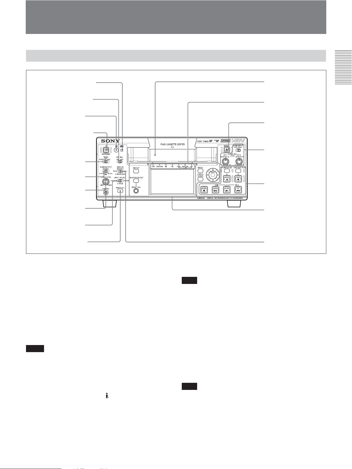
Location and Function of Parts
Front Panel
1 q (cassette) indicator
2 KEY INH (key inhibit)
switch
3 Remote sensor
4 ON/STANDBY switch
and lamp
5 TIMER switch
6 AUDIO OUTPUT
SELECT switch
7 PHONE LEVEL
control knob
8 PHONES jack
9 INPUT SELECT
switch
q; INDEX/(A1) button
qd Cassette
compartment
4 Indicator section
(see page 17)
qs EJECT (cassette
eject) button
3 Audio control section
(see page 16)
2 Tape transport control
section
(see page 14)
1 Monitor display
section
(see page 12)
qa DISPLAY OUTPUT
switch
Chapter 1 Overview
1 q (cassette) indicator
Lights when a digital video cassette is loaded.
Does not light up while the unit is not loading a
cassette.
This indicator blinks while a cassette is being ejected.
For details, see “Inserting/Ejecting Cassettes” on page 31.
2 KEY INH (key inhibit) switch
Turning on this switch disables all buttons to prevent
accidental button operations.
Notes
• Even when this switch is set to ON, the switches 5,
6, 9, qa, and 3-1, the switch 4 on the rear
panel, and the knobs 7 and 3-2 can be controlled.
• Even when you set this switch to ON, you can
operate the unit with Remote Commander, LANC
jack, CONTROL S jack, and
HDV/DV jack.
3 Remote sensor
Note
In addition to Remote Commander supplied with the
unit, the unit accepts signals from any Sony Remote
Commander whose command mode is set to VTR4. To
disable the control from Remote Commander, set
[COMMANDER] in [OTHERS] menu to [CONTROL
S].
4 ON/STANDBY switch and lamp
Press this switch to turn the unit on, and ON/
STANDBY lamp lights up green. When you press this
switch again, the unit goes into STANDBY mode and
the lamp lights up red.
Note
When KEY INH switch 2 is set to ON, ON/
STANDBY switch does not work. Set KEY INH
switch to OFF to enable ON/STANDBY switch.
(Continued)
Chapter 1 Overview 9
Page 10

Location and Function of Parts
5 TIMER switch
Use to select Auto Repeat or recording using an
external AC timer (not supplied).
REPEAT: When the power is supplied to the unit,
Chapter 1 Overview
the tape rewinds to its beginning automatically
and playback starts. When the following items on
the tape are searched, AUTO REPEAT playback
starts automatically.
–Index signals
– A portion unrecorded
– A portion recorded in the format set by other
than [AUTO] in [HDV/DV SEL] in [IN/OUT
REC] menu
– Tape end
Auto Repeat also functions if you set this switch to
REPEAT during playback or rewind.
For details on Auto Repeat, see “AUTO REPEAT
(CUSTOM REPEAT)” on page 39 and “CUSTOM
REPEAT” in “VTR SET” menu on page 74.
OFF: Auto Repeat or timer recording is released.
REC: Recording begins the moment the power is
connected to the unit.
Note
The setting of this switch still activates even when
KEY INH switch 2 is set to ON.
6 AUDIO OUTPUT SELECT switch
When the audio mode is 32 kHz (4-channel), use this
switch to select the audio channel to be output via
HDMI OUT jack, AUDIO jacks in OUTPUT as well
as PHONES jack 8.
CH-1/2: channels 1/2 only
MIX: channels 1/2 and channels 3/4
CH-3/4: channels 3/4 only
Notes
•During audio dubbing, if you want to listen to the
sound recorded on the tape, set this switch to CH-1/2;
if you want to listen to the sound being dubbed, set
the switch to CH-3/4. (Only channels 3 and 4 can be
used to dub.) To check the sound to be dubbed before
dubbing, set this switch to CH-3/4, then press
AUDIO DUB button while the unit is in the stop
mode. Then you can listen to the sound of the
channels used to dub (channels 3 and 4) at a moment.
For details on the audio dubbing, see page 60. Also refer
to the instructions of “AUDIO DUB / (A3) 1” button on
page 14.
•When the audio mode is 48 kHz (2-channel), sounds
of channel 1 and 2 are output via HDMI OUT jack,
AUDIO jacks in OUTPUT, and PHONES jack 8
regardless of the position of this switch.
•When this switch is set to MIX, the sound of the
mixed level of the pair of channel 1 and 3 and that of
channels 2 and 4 is output. The audio output level
becomes 50 % (–6 dB) of the original audio levels on
each channel.
7 PHONE LEVEL control knob
Controls the volume of the headphones connected to
PHONES jack 8.
8 PHONES jack
Connect stereo headphones for monitoring sounds
during recording or playback. The audio signals you
want to monitor can be selected with AUDIO
OUTPUT SELECT switch 6. By changing the setting
of [AUDIO MONI] in [AUDIO SET] (page 73), you
can monitor the sound of a particular channel.
9 INPUT SELECT switch
Switch the signal input jack from
HDV/DV jack, S
VIDEO jack, and VIDEO jack.
HDV/DV : Inputs a signal from
HDV/DV jack.
S VIDEO : Inputs a signal from S VIDEO jack.
VIDEO : Inputs a signal from VIDEO jack.
Notes
•Do not change the setting of this switch while
recording in progress, or it causes noise added to
images and sounds. Also, a part of the tape where the
change of setting applied will not be recorded
properly. The time code may be recorded
discontinuously.
• If you change the setting of this switch while
recording in progress, the output signal via
HDV/
DV jack may be interrupted. Also, the unit may
detect signals such as a copyright information signal
incorrectly.
•When a signal is input via
HDV/DV jack, the
settings of the menu listed below are unavailable.
– 60i/50i SEL
– AUDIO MODE
– AUDIO LOCK
– AUDIO INPUT LEVEL (–10/–2/+4) switch
– AUDIO REC LEVEL control knob
– AUDIO INPUT (AUTO/MANU) switch
10 Chapter 1 Overview
Page 11

q; INDEX/(A1) button
Press this button to write an index mark while
recording. Index is useful when you search for scenes
on a tape. Also, this button can be used as ASSIGN
(A1) button.
For detail on Index, see “Recording Functions” on page 47.
When you change ASSIGN buttons setting with
[ASSIGN (A1)] of [ASSIGN BTN] in [OTHERS]
menu, this button executes the function you have set.
For details on ASSIGN buttons, see “ASSIGN BTN” on
page 77.
qa DISPLAY OUTPUT switch
Selects the destination for the text data to be
superimposed via output jacks.
OFF : Does not superimpose text data to output
S VIDEO/VIDEO : Superimposes text data to S
VIDEO OUT jack and VIDEO jack.
ALL : Superimposes text data to HDMI OUT jack,
COMPONENT OUT jacks, S VIDEO OUT jack,
and VIDEO OUT jack.
qs EJECT button
Press this button to eject a cassette. If you press this
button while a cassette is inside the unit, the cassette is
ejected.
Chapter 1 Overview
qd Cassette compartment
Insert a standard-size or mini-size cassette.
For details on cassettes that can be used, see “Notes on
Power Supply and Video Cassettes” on page 30.
Chapter 1 Overview 11
Page 12
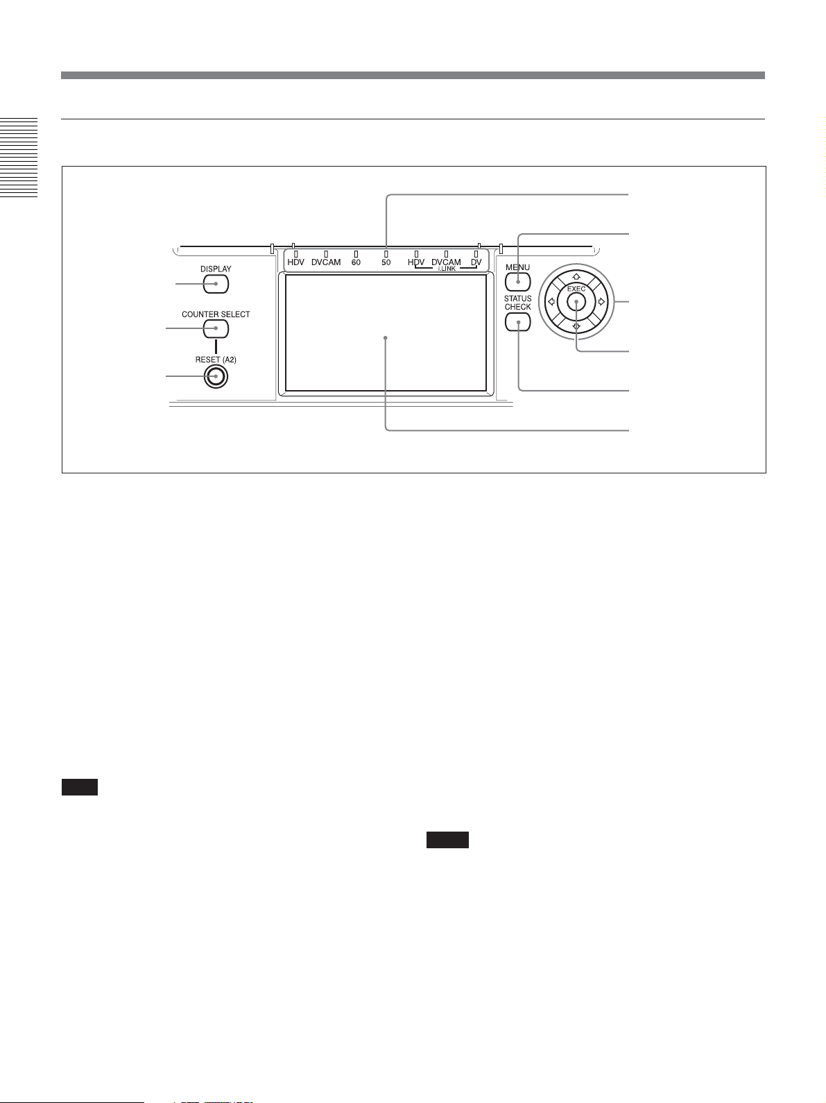
Location and Function of Parts
1 Monitor display section
Chapter 1 Overview
1 DISPLAY button
2 COUNTER
SELECT button
3 RESET/(A2)
(Counter reset)
button
1 DISPLAY button
Change the text data displayed on LCD monitor or the
text data output from video jacks on the rear panel of
the unit. By pressing this button, the unit displays the
picture only, picture and data, or picture and time
counter.
For details on various data, see “Displaying Various Data”
on page 25.
4 Indicator section
(see page 17)
4 MENU button
5 J/j/K/k
buttons
6 EXEC (execute)
button
7 STATUS
CHECK button
8 LCD (Liquid Crystal
Display) monitor
•A tape recorded using 50i system is being used in the
unit when [60i/50i SEL] in [OTHERS] menu is set to
[60i].
•A tape recorded using 60i system is being used in the
unit when [60i/50i SEL] in [OTHERS] menu is set to
[50i].
• [TC RUN] in [TC/UB SET] menu is set to [FREE
RUN].
2 COUNTER SELECT button
While displaying the data or time counter, press this
button to change the time counter display in the order
of time code, user bits, and tape counter.
Count value of the tape counter (seven digits) is
displayed on a ±12-hour cycle.
Note
The count value of the counter of the unit is
determined by calculation based on the time code, that
is, simple approximation. Therefore, in cases such as
the following, the value may be inaccurate.
• There is a portion where the time code is not
continuous on the tape you are using.
• The time code in both the drop frame mode and the
non-drop frame mode are recorded on the tape you
are using (for 60i only).
• There is a blank portion between recorded portions
on the tape you are using.
3 RESET (Counter reset)/(A2) button
Press this button, when the count value of the counter
is displayed. The count value is reset to 0:00:00:00.
Also, this button can be used as ASSIGN (A2) button.
When you change ASSIGN button setting with
[ASSIGN (A2)] of [ASSIGN BTN] in [OTHERS]
menu, this button executes the function you have set.
For details on ASSIGN buttons, see “ASSIGN BTN” on
page 77.
Notes
• This button does not reset the value of the time code
or user bits.
• To reset the value of the time code or user bits, use
[TC PRESET] or [UB PRESET] in [TC/UB SET]
menu.
12 Chapter 1 Overview
Page 13

4 MENU button
Press this button to display the menu on screen.
For details on the menu, see “Operating the Menus” on
page 65.
5 J/j/K/k buttons
Use these buttons in menu settings and other settings.
You can adjust the brightness of images by pressing
J/j buttons, while the data (format, the tape running
mode) is displayed on the LCD screen.
The display of the brightness level adjustment
disappears in a second after the adjustment completes.
While the time counter is displayed, the position of the
time counter moves up and down by pressing J/j
buttons. When the small size time counter is displayed,
the position of the time counter moves not only to the
up and down, but also to the right and left by pressing
K/k buttons.
While STATUS CHECK screen is displayed, you can
switch the screen by pressing J/j buttons.
6 EXEC (execute) button
Use this button in menu settings.
7 STATUS CHECK button
Press this button to check the audio level and menu
settings. To display STATUS CHECK screen, press
STATUS CHECK button.
Every time you press J/j buttons, STATUS CHECK
screen switches in the order of AUDIO, OUTPUT,
ASSIGN, and CUSTOM REPEAT. To hide STATUS
CHECK screen, press STATUS CHECK button again.
Chapter 1 Overview
Note
Audio level meter display varies depending on the
settings of [AUDIO MODE] in [AUDIO SET] menu,
AUDIO OUTPUT SELECT switch, and the audio
mode on the tape played back.
8 LCD (Liquid Crystal Display) monitor
Display the playback or EE
1)
pictures. Also,
superimposed time data, status information, menus,
audio level meters, etc. are displayed.
........................................................................................................................................................................................................
1) “EE” stands for “Electric to Electric.” In EE mode, the video and audio signals input to the VCR’s recording circuitry do
not pass through any magnetic conversion circuits but output via electric circuits only. This mode is used to check the input
signals and adjust input levels. The pictures output in EE mode are referred to as EE pictures.
Chapter 1 Overview 13
Page 14
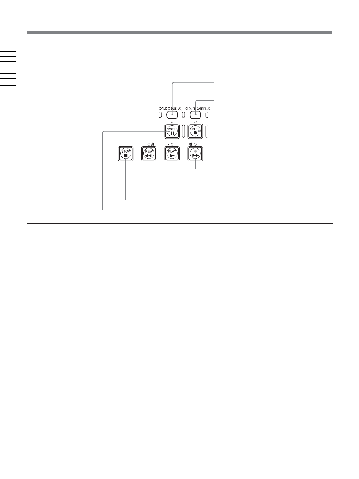
Location and Function of Parts
2 Tape transport control section
Chapter 1 Overview
1 AUDIO DUB (audio dubbing)/
(A3) button / indicator
2 DUPLICATE PLUS button
/ indicator
3 REC (record) button / indicator
4 FF (fast forward) button / indicator
5 PLAY button / indicator
6 REW (rewind) button / indicator
7 STOP button
8 PAUSE button / indicator
1 AUDIO DUB (audio dubbing)/ (A3) button /
indicator
Use this button to dub sounds. The indicator lights
while sounds are being dubbed. Also, this button can
be used as ASSIGN (A3) button.
For details on audio dubbing, see “Audio Dubbing” on
page 60.
When the unit is in the stop mode and INPUT
SELECT switch is set to other than HDV/DV, you can
check EE signals of the sound (channels 3 and 4) to be
dubbed by pressing this button. While the operation is
in progress, the indicator lights. To stop the operation,
press STOP button.
For details, see “EE/PB SEL” in “IN/OUT REC” menu on
page 71.
When you change ASSIGN buttons setting with
[ASSIGN (A3)] of [ASSIGN BTN] in [OTHERS]
menu, this button executes the function you have set.
For details on ASSIGN buttons, see “ASSIGN BTN” on
page 77.
2 DUPLICATE PLUS button/indicator
Use to duplicate a tape, including the time code. While
duplication is in progress, the indicator lights.
For details on the duplicate function, see “Duplication
(generating a work tape with the same time code)” on page
56.
When the unit is in the stop mode and HDV/DV
signals is selected and input, you can check EE signals
for an image, sound and time code by pressing this
button. While you are checking EE signals, the
indicator lights. To stop this operation, press STOP
button.
For details, see “EE/PB SEL” in “IN/OUT REC” menu on
page 71.
For details on time codes, see “HVR-M25U/M25N/M25E/
M25P time codes” on page 53.
3 REC (record) button / indicator
When you press and hold this button, then press PLAY
button, the each indicator lights and recording starts. If
you press this button while the tape is stopped, you can
check EE picture and audio signals for a moment.
When HDV/DV is selected, if [HDV/DV IN TC] in
[TC/UB SET] menu is set to [EXTERNAL], you can
also check the EE time code signals. Press STOP
button to end the check.
For details, see “EE/PB SEL” in “IN/OUT REC” menu on
page 71.
For details on time code, see “TC/UB SET” on page 75.
14 Chapter 1 Overview
Page 15

Notes
• The unit does not have an LP recording mode of the
consumer DV format. Only SP recording mode is
available.
• To set the unit to recording pause mode with the
remote control unit DSRM-10 (not supplied), press
PAUSE button while holding down PLAY button to
set the unit to the playback pause mode, then press
REC button on the DSRM-10.
• When the recording mode is set in HDV format, it
may take a few seconds to start recording. During this
time, REC indicator blinks.
4 FF (fast forward) button / indicator
When you press this button, the indicator lights and the
tape is fast forwarded. During fast forward, the picture
does not appear on the monitor. (you can see the
picture as it is seen in EE mode during fast forward.)
To locate a scene while monitoring the picture, keep
pressing this button during fast forward, playback or in
playback pause mode (picture search).
For details on [VTR SET] menu, see “VTR SET” on page
74.
6 REW (rewind) button / indicator
When you press this button, the indicator lights and the
tape starts rewinding. During rewind, the picture does
not appear on the monitor. (you can see the picture as
it is seen in EE mode during rewind.) To locate a scene
while monitoring the picture, hold this button down
during rewind, playback or in the playback pause
mode.
If you press PLAY button while holding down this
button during stop, the tape is rewound to its beginning
and starts playing automatically (during rewind, REW
indicator lights and PLAY indicator blinks).
For details on [VTR SET] menu, see “VTR SET” on page
74.
Notes
• If you set [EE/PB SEL] in [IN/OUT REC] menu to
[PB], EE picture and EE audio signals are not output.
• If you set [FF/REW SPEED] in [VTR SET] menu to
[SHUTTLEMAX], the picture is played back during
fast forward.
For details on running speed with [SHUTTLEMAX], see
“FF/REW SPEED” in “VTR SET” menu on page 74.
Chapter 1 Overview
Notes
• If you set [EE/PB SEL] in [IN/OUT REC] menu to
[PB], EE picture and EE audio signals are not output.
• If you set [FF/REW SPEED] in [VTR SET] menu to
[SHUTTLEMAX], the picture is played back during
fast forward.
For details on running speed with [SHUTTLEMAX], see
“FF/REW SPEED” in “VTR SET” menu on page 74.
5 PLAY button / indicator
When you press this button, the indicator lights and
playback begins.
If you press this button while holding down REW
button during stop, the tape is rewound to its beginning
and starts playing automatically (during rewind, REW
indicator lights and PLAY indicator blinks).
Notes
• When the unit is playing back a part of the tape
where the recording format has been changed among
HDV format, DVCAM format, and DV format, or
between 60i format and 50i format, the picture and
sound may be distorted.
• The unit cannot play back a tape recorded in the LP
recording mode of the consumer DV format.
7 STOP button
Press this button to stop the tape transport operation
completely.
8 PAUSE button / indicator
Press this button to set the unit to pause mode. The
indicator lights while recording, playing, or audio
dubbing. Press this button again to resume the
operation.
Chapter 1 Overview 15
Page 16
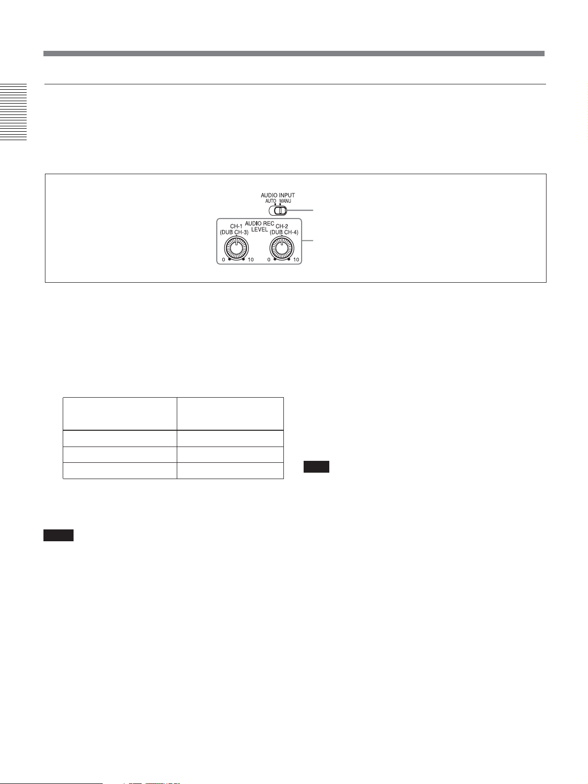
Location and Function of Parts
3 Audio control section
During normal recording, sounds are recorded onto
channels 1 and 2; they cannot be recorded
Chapter 1 Overview
onto channels 3 and 4. During audio dubbing, sounds
are dubbed onto channels 3 and 4.
1 AUDIO INPUT (AUTO/MANU) switch
2 AUDIO REC LEVEL control knob
1 AUDIO INPUT (AUTO/MANU) switch
Switches the audio recording level adjustment mode.
AUTO : Adjusts AUDIO REC LEVEL
automatically. (Adjustment of AUDIO REC
LEVEL control knobs 2 is disabled.)
For acceptable recording level, see the table
below.
AUDIO INPUT LEVEL Acceptable level
switch (max.)
–10 +18 dBu
–2 +24 dBu
+4 +30 dBu
MANU : Enables AUDIO REC LEVEL control
knobs 2.
Notes
•When i.LINK signals are input to the unit, the sound
recorded retains the signal level input, regardless of
the setting of this switch.
• Even this switch is set to AUTO, the setting is not
effective against the volume which exceeds the
dynamic range of the input amplifier.
• If you input a sound whose level exceeds the
acceptable range, the recorded sound is distorted.
2 AUDIO REC LEVEL control knobs
(CH-1 (DUB CH-3), CH-2 (DUB CH-4) )
To perform normal recording using these knobs, adjust
the levels of the analog audio signals input to the unit
(channel 1 and 2). To perform audio dubbing using
these knobs, adjust the levels of channel 3 and 4.
These knobs are enabled only when AUDIO INPUT
(AUTO/MANU) switch 1 is set to MANU.
To display the audio level meters on LCD monitor,
press STATUS CHECK button.
For details on the audio level meter, see “STATUS CHECK
screen” on page 27.
Note
You cannot adjust the audio level using these knobs
while i.LINK signals is input.
16 Chapter 1 Overview
Page 17
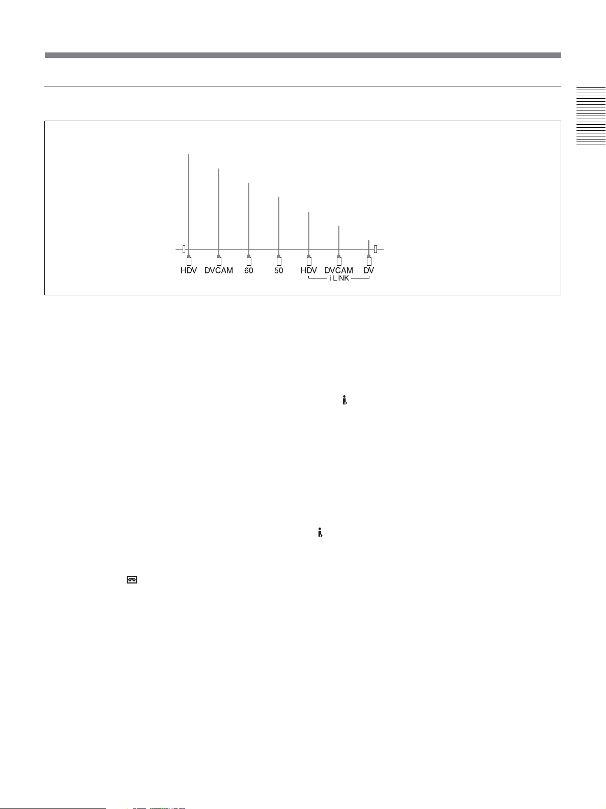
4 Indicator section
1 HDV indicator
2 DVCAM indicator
3 60 indicator
4 50 indicator
1 HDV indicator
Lights when the unit is in the following operating
status.
•When a tape recorded in HDV format is being played
back.
•When HDV signals are input through the i.LINK
interface.
•When [HDV/DV SEL] in [IN/OUT REC] menu is set
to [HDV].*
* Even when [HDV/DV SEL] in [IN/OUT REC] menu is
set to [AUTO] with no signal input, while the last signal
input was HDV format or the last tape played was HDV
format, this indicator lights.
2 DVCAM indicator
Lights when the unit is in the following operating
status.
• When a tape recorded in DVCAM format is being
played back.
• When [HDV/DV SEL] in [IN/OUT REC] menu is
set to [DV] and [
REC MODE] in [IN/OUT REC]
menu is set to [DVCAM] (during recording or in EE
mode).*
* Neither HDV indicator nor DVCAM indicator lights
during recording in DV (SP) format or a playback of a
tape recorded in DV (SP) format.
5 HDV-i.LINK indicator
6 DVCAM-i.LINK indicator
7 DV-i.LINK indicator
3 60 indicator
Lights when the unit is in the following operating
status.
•During recording or in EE mode when [60i/50i SEL]
in [OTHERS] menu is set to [60i].
•During HDV1080/60i or NTSC signals are input
from
HDV/DV jack.
•A tape that has HDV1080/60i or NTSC signals is
being played back.
4 50 indicator
Lights when the unit is in the following operating
status.
•During recording or in EE mode when [60i/50i SEL]
in [OTHERS] menu is set to [50i].
•During HDV1080/50i, or PAL signals are input from
HDV/DV jack.
•A tape that has HDV1080/50i or PAL signals is being
played back.
5 HDV-i.LINK indicator
Lights when HDV signals are input/output through the
i.LINK interface.
6 DVCAM-i.LINK indicator
Lights when DVCAM signals are input/output through
the i.LINK interface.
Chapter 1 Overview
7 DV-i.LINK indicator
Lights when DV signals are input/output through the
i.LINK interface.
Chapter 1 Overview 17
Page 18
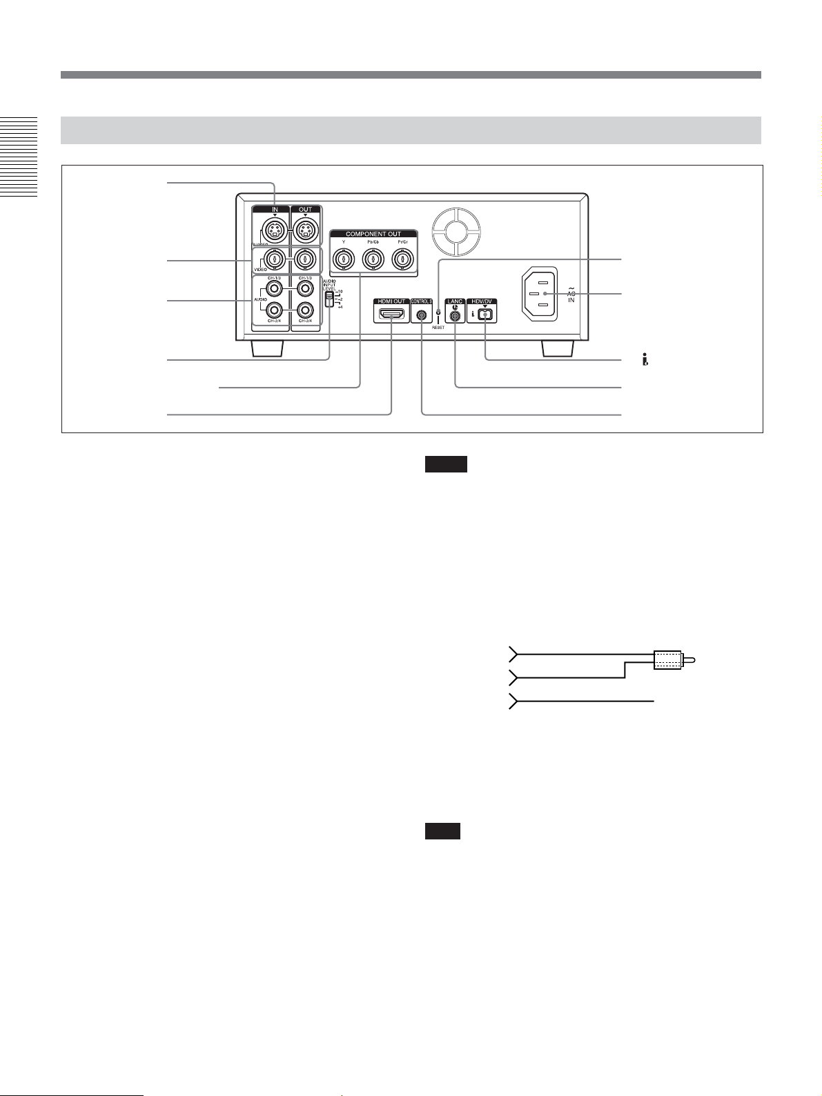
Location and Function of Parts
Rear Panel
1 S VIDEO jacks
Chapter 1 Overview
2 VIDEO jacks
3 AUDIO jacks
4 AUDIO INPUT
LEVEL switch
5 COMPONENT OUT jacks
6 HDMI OUT jack
1 S VIDEO jacks
To connect a device equipped with S video jack, use S
VIDEO jacks on the unit.
If you use S VIDEO jacks, you can input/output highquality video with less signals deterioration in quality
than the one connected to the standard VIDEO jack.
When DISPLAY OUTPUT switch is set to S VIDEO/
VIDEO or ALL, text data such as the time code,
menus, and alarm messages are superimposed on an
external monitor connected to S VIDEO jack (page
25).
For details on the output of S VIDEO jack, see “Notes on all
video output jacks” (page 22).
7 RESET button
8 AC IN connector
9 HDV/DV jack
q; LANC jack
qa CONTROL S jack
Notes
• In the audio dubbing mode, CH1/3 and CH2/4 jacks
function as the channel 3 and channel 4 input jacks,
respectively.
• To input balanced audio signals via AUDIO jacks,
use a conversion cable as shown below. (The COLD
side is open.)
For details on conversion cables, refer to the instruction
manual of the devices you use.
GND
HOT
2 VIDEO jacks
Use to input and output analog video signals.
Text data is superimposed on a monitor in the same
way as S VIDEO jack connection (page 25).
For details on the output of VIDEO jack, see “Notes on all
video output jacks” (page 22).
3 AUDIO jacks
Use to input and output analog audio signals.
During normal recording, sounds are recorded onto
channels 1 and 2. During audio dubbing, sounds are
dubbed onto channels 3 and 4. When the audio mode is
FS32K (4 channel), if you set AUDIO OUTPUT
SELECT switch to MIX, the audio output level
becomes 50% (-6 dB) of the original audio level on
each channel.
18 Chapter 1 Overview
COLD ×
4 AUDIO INPUT LEVEL (–10/–2/+4) switch
Select one from –10 dB, –2 dB, or +4 dB according to
the audio level of the signal input via AUDIO IN
jacks.
Note
If this switch setting is not appropriate, clipping
distortion or noise may occur.
For more information on the setting of this switch, see
“When you set AUDIO INPUT LEVEL switch” on page 86.
Page 19

5 COMPONENT OUT jacks
Use to output component signals.
To connect a device equipped the component video
input connector, use COMPONENT OUT jacks on the
unit. If you use COMPONENT OUT jacks, you can
output high-quality video with less signal deterioration
in quality than S VIDEO jack.
You can set the output video format by using [HDMI/
CMPNT] of [VIDEO OUT] in [IN/OUT REC] menu.
When DISPLAY OUTPUT switch is set to ALL, text
data such as time code, menu, and alarm message are
superimposed on a monitor connected using
COMPONENT OUT jacks (page 25).
Notes
•When images are output in 720p format, some of the
text image data (outer frame: underscan portion) on
the monitor may appear cut out. In this case, check
the text image data on LCD monitor of the unit or on
a monitor using S VIDEO OUT jack or the VIDEO
OUT jack. Also, when your monitor has an underscan
function, you can check all the text data on the
monitor during underscan.
•When you change the video format setting of [HDMI/
CMPNT] of [VIDEO OUT] in [IN/OUT REC] menu,
the video signal output from S VIDEO jack, VIDEO
jack, or
HDV/DV jack may be distorted for a
moment.
•When you play back an HDV-formatted tape with
copyright protected signals or input HDV signals
with copyright protection to
HDV/DV jack, pictures
may be output in either 480i (NTSC) or 576i (PAL)
format, regardless of the setting of [HDMI/CMPNT]
of [VIDEO OUT] in [IN/OUT REC] menu.
•When you play back a tape in DVCAM/DV format
and while an EE picture in NTSC/PAL is displayed,
the 480i resolution or the 576i resolution is output,
regardless of the setting of [HDMI/CMPNT] of
[VIDEO OUT] in [IN/OUT REC] menu.
• The output level of COMPONENT OUT jacks is as
follows:
Output at 480i NTSC
With [BETACAM] selected in [IN/OUT REC] menu
Y: 1.0 Vp-p
(with 0.286 Vp-p sync negative,
output impedance 75 Ω (ohms), unbalanced)
Pb/Cb/B-Y, Pr/Cr/R-Y: 0.7 Vp-p
(output impedance 75 Ω (ohms), unbalanced)
(75% color bars with 7.5 IRE setup)
With [SMPTE] selected in [IN/OUT REC] menu
Y: 1.0 Vp-p
(with 0.3 Vp-p sync negative,
output impedance 75 Ω (ohms), unbalanced)
Pb/Cb/B-Y, Pr/Cr/R-Y: 0.7 Vp-p
(output impedance 75 Ω (ohms), unbalanced)
(100% color bars with no setup)
Output with other settings
Y: 1.0 Vp-p
(output impedance 75 Ω (ohms), unbalanced)
Pb/Cb/B-Y, Pr/Cr/R-Y: 0.7 Vp-p
(output impedance 75 Ω (ohms), unbalanced)
(100% color bars with no setup)
480i/480p:
Y: with 0.3 Vp-p sync negative
1080i/720p:
Y/Pb/Pr: with 0.6 Vp-p 3-level sync
Chapter 1 Overview
(Continued)
Chapter 1 Overview 19
Page 20

Location and Function of Parts
6 HDMI OUT jack
Use to output HDMI signals. HDMI OUT jack outputs
both pictures and audio.
To connect a device which equipped HDMI input
connector, use HDMI OUT jack on the unit.
Chapter 1 Overview
HDMI OUT jack outputs high-quality video with even
less signal deterioration in quality than COMPONENT
OUT jacks.
You can set the output video format by using [HDMI/
CMPNT] of [VIDEO OUT] in [IN/OUT REC] menu.
Text data is superimposed on a monitor in the same
way as COMPONENT OUT jacks connection (page
25).
Notes
Use an HDMI cable with HDMI logo.
When you connect the unit with other device, some of
the devices do not display pictures or sounds. Also,
when you connect the unit in the way described below,
the unit or the device connected to the unit may be
damaged.
–When HDMI OUT jack on the unit is connected to
the HDMI OUT jack on the device.
–When HDMI OUT jack on the unit is connected to
the HDMI OUT jack of the same unit.
There are following restrictions on the output of HDMI
OUT jack.
•When you play back an HDV-formatted tape with
copyright protected signals or input HDV signals,
including copyright protected signals via
jack, pictures and audio cannot be output from HDMI
OUT jack. (Copy-protected signals and programs
such as digital broadcasts are also included.)
•You cannot output EE picture of analog video
(NTSC, PAL) that are input from VIDEO IN jack, S
VIDEO IN jack to HDMI OUT jack. In this case, text
data and menus cannot be displayed either. When you
play back a DVCAM or DV (SP)-formatted tape
recorded in either NTSC or PAL format, pictures are
output to HDMI OUT jack.
•You cannot output EE picture and sound of DVCAM/
DV signals (NTSC, PAL) that are input from
DV jack to HDMI OUT jack.
• Sounds output via HDMI OUT jack of the unit is 2-
channel (stereo). In case of playing back a tape
recorded in 4-channel (32 kHz), audio recording, or
pausing audio recording, to output the sound of CH3
and CH4 during post recording, select CH-3/4 with
AUDIO OUTPUT SELECT switch. By selecting
MIX with this switch, mixed sounds can be output to
HDMI OUT jack as well.
HDV/DV
HDV/
• Sounds output via HDMI OUT jack are output with
16 bit of 48 kHz, 2-channel linear PCM mode
regardless of the tape played back, the setting of the
menus, or the signal format input to
HDV/DV jack.
•When images are output in 720p format, some of the
text image data (outer frame: underscan portion) on
the monitor may appear cut out. In this case, check
the text image data on LCD monitor of the unit or on
a monitor using S VIDEO OUT jack or VIDEO OUT
jack. Also, when your monitor has an underscan
function, you can check all the text data on the
monitor during full screen underscan.
•When you change the video format setting of [HDMI/
CMPNT] of [VIDEO OUT] in [IN/OUT REC] menu,
the video signal output from S VIDEO jack, VIDEO
jack, or
HDV/DV jack may be distorted.
• If a monitor or other device connected to the unit
does not have a resolution display mode selected with
[HDMI/CMPNT] of [VIDEO OUT] in [IN/OUT
REC], noise may occur on the picture of the monitor,
or a humming noise may be output from the speakers.
Also, the picture may not be displayed or the sound
may not be output. Be sure to check the displayable
resolutions of the monitor by referring the operational
instructions of your monitor, and select the
appropriate menu for the unit.
•Depending on the monitor you have, the picture and
sound on the monitor may be distorted when you
change the resolution of the picture. This is not a
malfunction.
• Some monitors have a specification that does not
allow them to display personal contents (such as a
movie recorded for private use) played on the unit.
To play the video properly, use COMPONENT OUT
jacks or VIDEO jacks to connect the monitor and the
unit.
7 RESET button
If you press this button with the tip of a ballpoint pen
or similar tool, the following settings are initialized.
–[CLOCK SET] (page 78) and [60i/50i SEL] (page
79) in [OTHERS] menu.
– The setting on the unit except the menu settings.
8 AC IN connector
Connects to an AC outlet using the supplied power
cord.
Even if the unit is in the standby mode, it consumes
power. To turn the unit off completely, pull the plug
out from the AC outlet.
20 Chapter 1 Overview
Page 21

9 HDV/DV jack (4-pin)
Use this jack to input/output the digital signals that
complies with the i.LINK standard. Use when a device
connected to the unit has an i.LINK jack. If you
connect the unit and another device using
HDV/DV
jack, you can minimize deterioration of picture quality
during recording, dubbing, or capturing still pictures,
all by means of digital signals processing.
For details, refer to the instruction manual of the external
device.
Notes
•When you connect with the i.LINK cable to a
computer and the unit, check the direction of the jack.
If you forcibly insert the jack, the terminal may be
damaged or cause the unit to malfunction. Align v
mark of the i.LINK cable with V mark on the unit
and insert the i.LINK cable.
• This jack is only compatible with HDV (1080i)/
DVCAM/DV signals.
For details, see “About i.LINK” on page 98.
• If video signals have been input to HDV/DV jack
and you output these video signals to the S VIDEO or
VIDEO connectors, the sync and burst of the
corresponding EE picture is not synchronized.
• If the unit is connected to a device equipped with an
i.LINK jack, when you intend to disconnect or
reconnect the i.LINK cable, turn off the device and
pull out the plug of its power cord from the AC outlet
beforehand. If you connect or disconnect the i.LINK
cable while the device is connected to the AC outlet,
high-voltage current (8 to 40 V) is output from
i.LINK jack of the device to the unit. This may cause
a malfunction.
•When connecting a device that has a 6-pin i.LINK
jack to the unit, connect the plug of the cable to the 6pin i.LINK jack first.
For details on each setting when HDV/DV signals are
input, see “HDV/DV SEL” (page 67).
• Video signal which is input from HDV/DV jack
will be output directly to COMPONENT OUT jacks,
S VIDEO jack, and VIDEO jack with the jitter of
i.LINK signal. This jitter may be displayed on the
connected monitor. Be aware of this jitter when you
connect other recording device to for these jacks.
This jitter will not appear on a recording with the
unit.
•When you change the video format setting of [HDMI/
CMPNT] in [VIDEO OUT] of [IN/OUT REC] menu,
the video signal output from S VIDEO OUT jack,
VIDEO OUT jack, or
HDV/DV jack may be
distorted.
For details on the output of HDV/DV jack, see “Notes on
all video output jacks” (page 22).
q; LANC jack
Use this jack when controlling the tape transport
operation of the unit using a device that has a LANC
1)
jack.
Notes
• LANC jack on the unit has only LANC-S functions.
The unit has no LANC-M functions. A device that is
set to LANC-S mode cannot be connected to the unit.
Either this, the unit or the other device may not
operate properly.
•When using the unit as a player, set LANC mode on
the recorder to M. A VCR that does not have M/S
switching function cannot be used to control the unit.
• When the device for connecting to the unit has
[LANC-M] function to switch between SHUTTLE A/
B, select SHUTTLE A for HDV-formatted tape, and
SHUTTLE B for the DVCAM/DV (SP)-formatted
tape.
• LANC connection transmits command signals for
playback, stop, pause playback, as well as the time
code, tape counter, and data status of the unit.
• Jacks labeled CONTROL L have the same function
as LANC jacks.
• There are some limitations when you edit an HDVformatted tape.
Refer to the “Notes” in “Editing (Connecting with a
Computer)” on page 62.
qa CONTROL S jack
Connect to a remote control unit DSRM-10 (not
supplied) for controlling the unit.
You can use DSRM-20 (no longer manufactured: not
supplied).
Note
When you use a CONTROL S device, set
[COMMANDER] in [OTHERS] menu to [CONTROL
S].
Chapter 1 Overview
(Continued)
........................................................................................................................................................................................................
1) LANC (Local Application Control bus system):
Bidirectional interface used to control a consumer VCR
Chapter 1 Overview 21
Page 22

Location and Function of Parts
Notes on all video output jacks
• When you change the video format setting of
[HDMI/CMPNT] and [DOWN COVERT] of
[VIDEO OUT] in [IN/OUT REC] menu, [ALLSCAN
Chapter 1 Overview
MODE] in [DISPLAY SET] menu, or [HDV t DV
CONV] and [DOWN CONVERT] in [i.LINK SET],
the image may be distorted for a moment. Also, the
above settings may cause the restrictions on the video
output of the unit.
For details, refer to the table on page 85 and the
instructions of each menu setting.
• When you change the video format setting of
[HDMI/CMPNT] of [VIDEO OUT] in [IN/OUT
REC] menu, the video signals output from S VIDEO
OUT jack, VIDEO OUT jack, or
HDV/DV jack
may be distorted.
• The unit is only compatible with standard video
signals. If you input the types of video signals shown
below, recorded picture and sound may be distorted.
– Signals from some home game machines
–Blue background screen or gray background screen
from a consumer VCR
– Pictures played at a speed other than normal by a
VCR that does not have the TBC (Time Base
Corrector)
–Video signals in which the sync signals are
distorted
– Signals from a defective cassette (tape or recording
condition is bad) played by an analog VCR that
does not have TBC
• To absorb the jitter of input video signals, the
distortion of video signals are processed in the
underscan portion. You may see this procedure on an
underscan monitor, yet this is not a malfunction.
Also, the picture recorded on the tape will not be
affected.
•During recording or in EE mode, the subcarrier of the
color signal to be output from the unit is not
synchronized with the horizontal sync signal. The
color of the picture or the horizontal position of the
picture may be distorted depending on the type of
monitor connected to the unit.
• To output video signals to VIDEO, S VIDEO, or
COMPONENT OUT jacks without text data, set
DISPLAY OUTPUT switch to OFF, or press DATA
CODE or SEARCH SELECT button on the remote
commander.
22 Chapter 1 Overview
Page 23
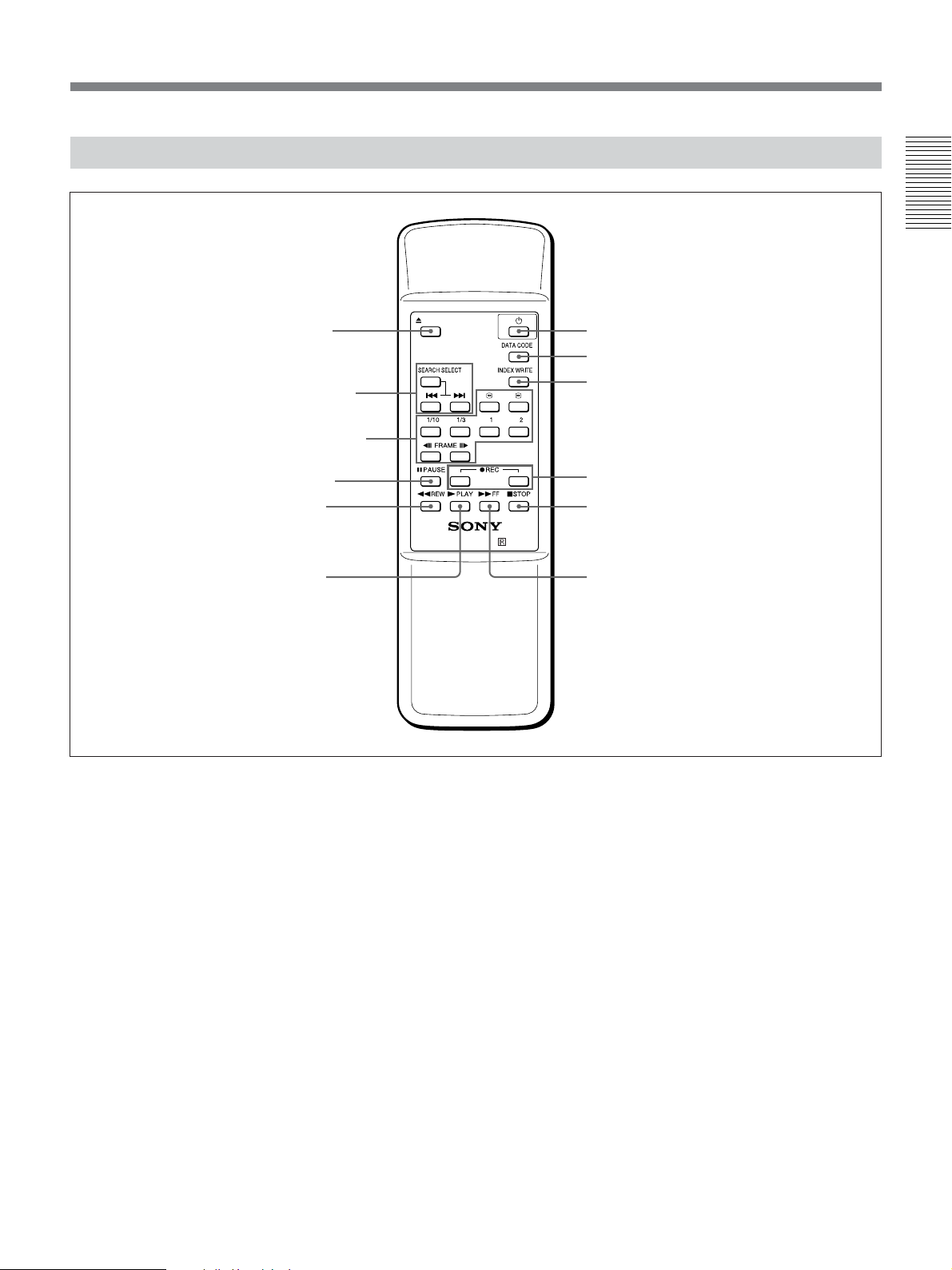
Supplied Remote Commander
Chapter 1 Overview
1 EJECT button
2 SEARCH SELECT
buttons
3 Buttons for playing
at various speeds
4 PAUSE button
5 REW button
6 PLAY button
EJECT
××××
VTR RMT-DS5
qs 1 switch
qa DATA CODE button
0 INDEX WRITE button
9 REC buttons
8 STOP button
7 FF button
1 EJECT button
2 SEARCH SELECT buttons
Press these buttons to search for scenes using the
search function.
For details on the search function, see “Searching using the
search function” on page 38.
3 Buttons for playing at various speeds
You can play back a tape at normal speed or at a speed
other than normal with these buttons.
For details, see “Playing at various speeds” on page 37.
4 PAUSE button
5 REW (rewind) button
6 PLAY button
7 FF (fast forward) button
8 STOP button
9 REC (record) buttons
When you press both these buttons at the same time,
REC indicator and PLAY indicator on the front panel
light and recording begins.
0 INDEX WRITE button
Press this button during recording to mark an index.
For details on an index, see “Marking an index” on page
47.
qa DATA CODE button
Press this button to display the data codes (recording
date/time, camera data).
For details on data codes, see “Displaying information
(data codes) recorded on a tape” on page 36.
qs 1 (on/standby) switch
(Continued)
Chapter 1 Overview 23
Page 24
Location and Function of Parts
Notes
• The command mode of the supplied Remote
Commander is set to VTR4. You cannot change
command mode setting.
• Set [COMMANDER] in [OTHERS] menu to
Chapter 1 Overview
[WIRELESS] to enable Remote Commander to
control the unit.
• In addition to Remote Commander supplied with the
unit, the unit accepts signals from any Sony Remote
Commander whose command mode is set to VTR4.
To disable the control from Remote Commander, set
[COMMANDER] in [OTHERS] menu to
[CONTROL S].
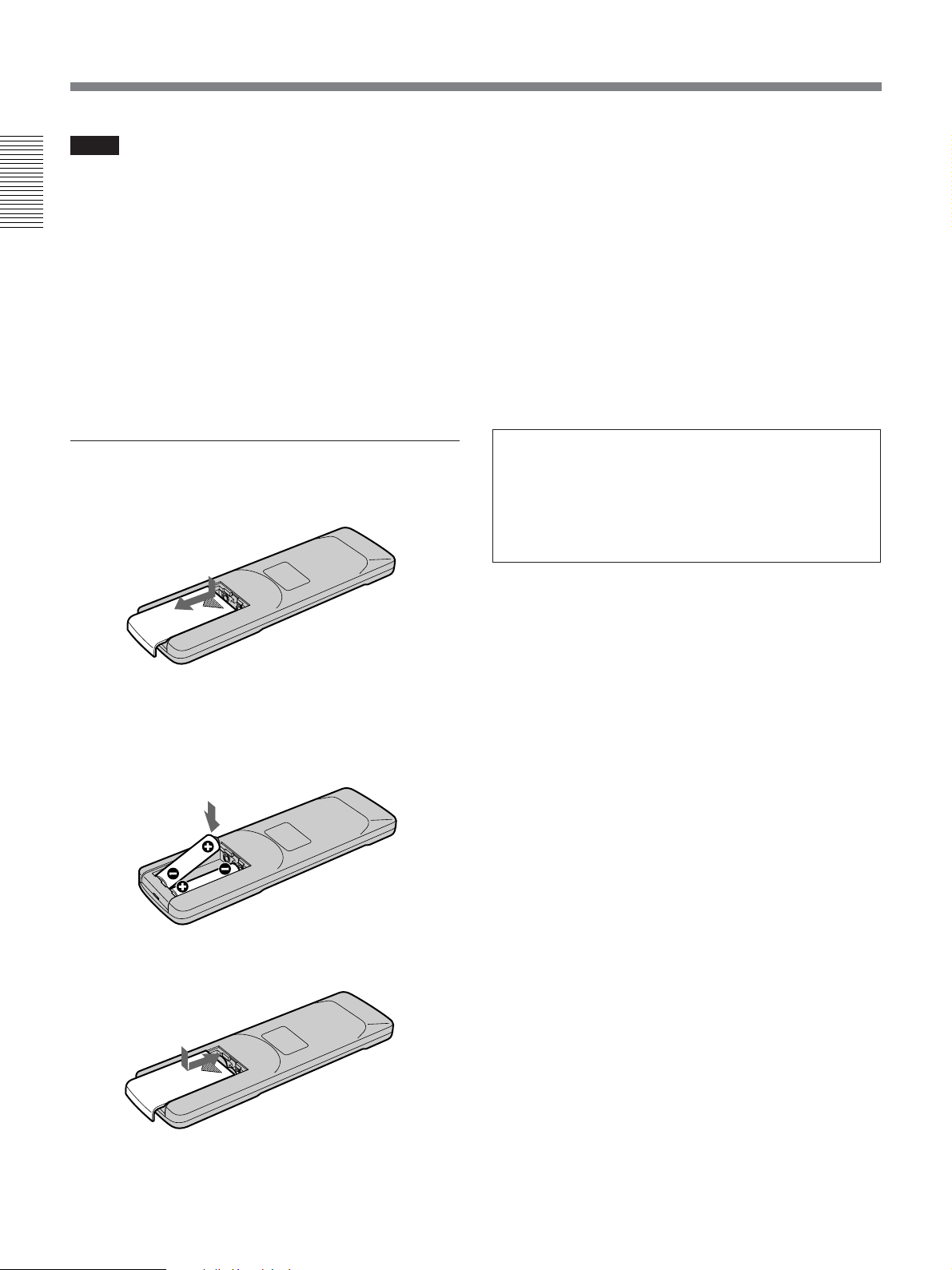
Battery installation
1 Push and slide the lid to open.
Notes on batteries
• Make sure that the battery orientation is correct when
inserting batteries.
• Do not mix an old battery with a new one, or mix
different types of batteries.
• If you do not intend to use Remote Commander for a
long time, remove the batteries to avoid damage from
battery leakage. If the batteries have leaked, remove
them, wipe the battery compartment dry and replace
the batteries with new ones.
To remove the batteries
Remove the lid as step 1 and take out the batteries.
WARNING
Battery may explode or leak if mistreated. Do not
recharge, disassemble or dispose of in fire.
Check the valid date (month-year) displayed on
the batteries.
2 Install two size AA (R6) batteries (supplied) with
the correct polarity.
Be sure to install the
battery from the # side.
3 Put the lid back.
24 Chapter 1 Overview
Page 25
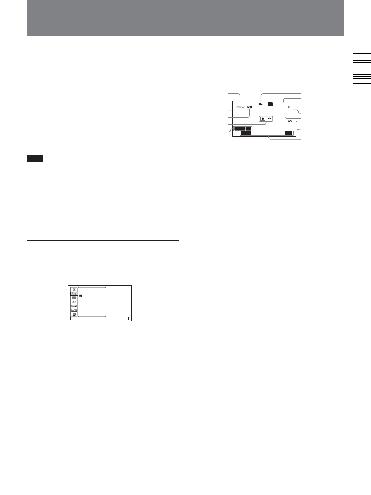
Displaying Various Data
The unit can display various superimposed text data on
the built-in LCD monitor and also an external monitor
connected to the unit.
To display text data on an external monitor, set
DISPLAY OUTPUT switch to ALL or S VIDEO/
VIDEO. You can turn ON/OFF various text data
display by pressing DISPLAY button.
In this operation manual, the menu screen etc. is
displayed in English. You can change the desired
language with the screen language setting.
For details, see page 77.
Note
When images are output in 720p format, some of the
text image data (outer frame: underscan portion) may
appear cut out, depending on the displayable range of
the monitor. In this case, check the text image data on
LCD monitor of the unit or on a monitor using S
VIDEO OUT jack or VIIDEO OUT jack. Also, when
your monitor has an underscan function, you can check
all the text data on the monitor during the underscan.
Data display
You can confirm important information for normal
recording or playback, such as time code or remaining
tape time, on the screen.
1
2
3
4
5
sc
AUTO
A3A2A1
TC
00:12:34:12
60min
HDV/DV
INDEX 00
SEARCH
18018
dB
F1.4 ATW
6
7
8
IN
9
0,qa
qs
qd
1 Format indicator
[HDV1080i], [DVCAM], or [DV SP] are displayed.
2 Repeat indicator
Displays an repeat indicator when TIMER switch is set
to REPEAT. When [START TIME] of [CUSTOM
REPEAT] is set to [ON] in [VTR SET] menu,
c
is
also displayed (page 10).
3 60i/50i indicator
Chapter 1 Overview
Menu screen
Press MENU button to display the menu screen.
For details on the menu, see “Chapter 5 Adjusting and
Setting Through Menus” on page 65.
IN/OUT REC
HDV/DV SEL
REC MODE
VIDEO OUT
i.LINK. SET
CROP ADJUST
CROP MARKER
COLOR BAR
[
MENU] : END
Data display screen
You can display the picture, picture and data, or
picture and the time counter on the data screen by
pressing DISPLAY button when the unit is turned on.
4 Alarm indicator
Displays an alarm indicator.
For details on alarm indicators, see “Warning indicators
and messages” on page 87.
5 ASSIGN buttons indicator
Displays ASSIGN button indicator when each
ASSIGN button is set other than default functions.
For details on “ASSIGN buttons”, see page 77.
6 Tape transport mode indicator
Displays the tape transport mode.
(Continued)
Chapter 1 Overview 25
Page 26
Displaying Various Data
7 Time counter (time code/user bits/count value of
the counter) indicator
Displays the count value of the counter, time code, or
user bits. By pressing the COUNTER SELECT button
on the front panel, you can select the item to be
Chapter 1 Overview
displayed.
When the time code is displayed,
TC
appears to its left.
In the drop frame mode, a period is displayed between
the minutes and seconds (i.e., 00:12.58:00).
When the user bits are displayed,
UB
appears to their
left.
When the count value of the counter is negative, “–”
appears as the first digit (leftmost digit). When that
value is positive, the first digit is blank.
The count value of the counter consists of seven digits.
If the self-diagnostic function is enabled, diagnostics
code numbers are displayed.
Note
When you playback a tape without a time code or with
a time code recorded in different formats, the time
code cannot be displayed correctly.
8 Remaining tape time indicator
Displays the remaining tape time.
For details, see “ REMAINING” on page 72.
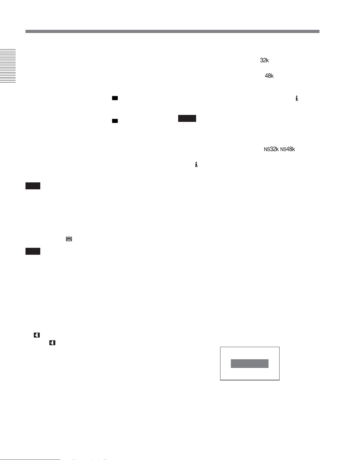
qs Audio mode indicator
In the recording mode, displays
when you select
[FS32K] for [AUDIO MODE] in [AUDIO SET]
menu. When you select [FS48K],
is displayed.
During playback or audio dubbing, displays the audio
mode recorded on the tape. During i.LINK input,
displays the audio mode of the signal input to
HDV/
DV jack.
Notes
• The audio mode will not be displayed when [HDV/
DV SEL] in [IN/OUT REC] menu is set to [HDV].
• Signals other than HDV/DVCAM lock mode will
become non-standard audio and
/ is
displayed during playback or when the signal is input
from
HDV/DV jack.
qd Date/time and camera data indicator
When you press DATA CODE button of Remote
Commander or set [DATA CODE] in [DISPLAY
SET] menu to [DATE] or [CAMERA DATA], you can
switch the display between recording date/time and
camera data.
For details on the date/time and camera data indicator, see
“Displaying information (data codes) recorded on a tape”
on page 36.
Note
When you insert a cassette in which the tape has been
rewound to the beginning, this indicator does not show
the remaining tape time. The remaining tape time is
displayed after the tape runs for a while.
9 INPUT SELECT indicator
Changes according to the position of INPUT SELECT
switch. ([HDV/DV IN], [S VIDEO IN] or [VIDEO
IN])
0
(Index) indicator
Displays
when an index has been marked.
qa Search indicator
Displays the search mode when you search for scenes
using Remote Commander.
For details on the search function, see “Searching using the
search function” on page 38.
Time counter screen
To display the time counter on LCD panel, press
DISPLAY button. On the time counter screen, it
displays the time data (count value of the counter/time
code/user bits).
While the time counter is displayed, the position of the
time counter moves up and down by pressing J/j
buttons. When the small size time counter is displayed,
the position of the time counter moves not only to the
up and down, but also to the left and right by pressing
K/k buttons.
00:10:26:12
26 Chapter 1 Overview
Page 27
When the count value of the counter is negative, “–”
appears as the first digit (leftmost digit). When that
value is positive, the first digit is blank. When the
format of the displayed time code is the drop frame
mode, the drop frame indicator is displayed as a
period between the minutes and seconds (i.e.,
00:12.58:00).
When user bits are displayed, the space between hour,
minute, and second becomes blanked.
Notes
• In the playback mode, if the tape has a portion where
recorded signals are not continuous:
– The count value of the counter may not advance
correctly from that portion.
– The displayed value of the time code or user bits
may be temporarily inaccurate.
•When the unit plays back a part of the tape where the
recorded system has been changed between 50i and
60i, the displayed value may be inaccurate.
•When the unit plays back a part of the tape where the
recording format has been changed among HDV,
DVCAM and DV, the displayed value may be
inaccurate.
• The counter operates on a ±12-hour cycle. You
cannot make the counter operate on a 24-hour cycle.
• The count value of the counter consists of seven
digits. The tens place of the “hour” is not displayed.
(i.e., If the actual count value is “11:22:11:22”, the
displayed value will be “1:22:11:22.”) However, the
unit recognizes that the hours value is “11”.
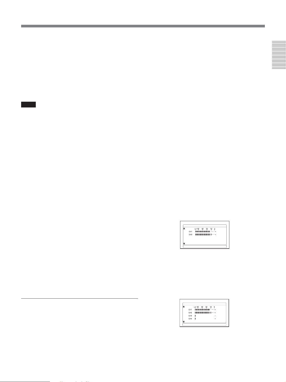
Audio Level Meter and Audio setting screen
Audio Level Meter and Audio setting screen is
displayed when STATUS CHECK screen is set to
[AUDIO].
This screen displays the audio level meter and the
setting values of [AUDIO MONI] in [AUDIO SET]
menu.
For details, see “AUDIO SET” on page 73.
Audio Level Meter
Audio Level Meter can be used to confirm and adjust
the audio level. Audio Level Meter is displayed in
different patterns, depending on the settings of
[AUDIO MODE] and AUDIO OUTPUT switch.
The unit detects the audio mode as follows:
In the playback mode: Detects the audio mode
recorded on the tape.
In the recording/EE mode: Detects the selected
audio mode in [AUDIO MODE] in [AUDIO SET]
menu.
When INPUT SELECT switch is set to HDV/DV
and HDV or DV signals is being input: Detects
the audio mode of the signals being input. (The
setting of [AUDIO MODE] in [AUDIO SET] menu
becomes invalid.)
Audio mode: 48 kHz (2-channel, 16 bits)
AUDIO
1/4
Chapter 1 Overview
Setting the time counter
You can adjust the settings of the time counter display
in [COUNTER SET] in [DISPLAY SET] menu.
DISPLAY : Selects whether to display the time
counter or not.
SIZE : Selects the size of the time counter.
COLOR : Selects the color of the time counter.
For details on [COUNTER SET], see page 71.
STATUS CHECK screen
To display STATUS CHECK screen, press STATUS
CHECK button.
Each time you press J/j button, STATUS CHECK
screen switches in the order of AUDIO, OUTPUT,
ASSIGN, and CUSTOM REPEAT.
To hide STATUS CHECK screen, press STATUS
CHECK button again.
AUDIO MONI:
[
STATUS CHECK] : END
CH1 , CH2
(The levels of two channels, channels 1 and 2, are
displayed.)
Audio mode: 32 kHz (4-channel, 12 bits)
(a) When AUDIO OUTPUT SELECT switch is set to
CH-1/2 or CH-3/4
AUDIO
AUDIO MONI:
[
STATUS CHECK] : END
CH1 , CH2
(The levels of four channels, channels 1 to 4, are
displayed. During playback, if the sounds are recorded
onto channels 3 and 4, their levels meters fluctuate.
However, during normal recording, you cannot record
sounds onto the channels 3 and 4.)
1/4
(Continued)
Chapter 1 Overview 27
Page 28
Displaying Various Data
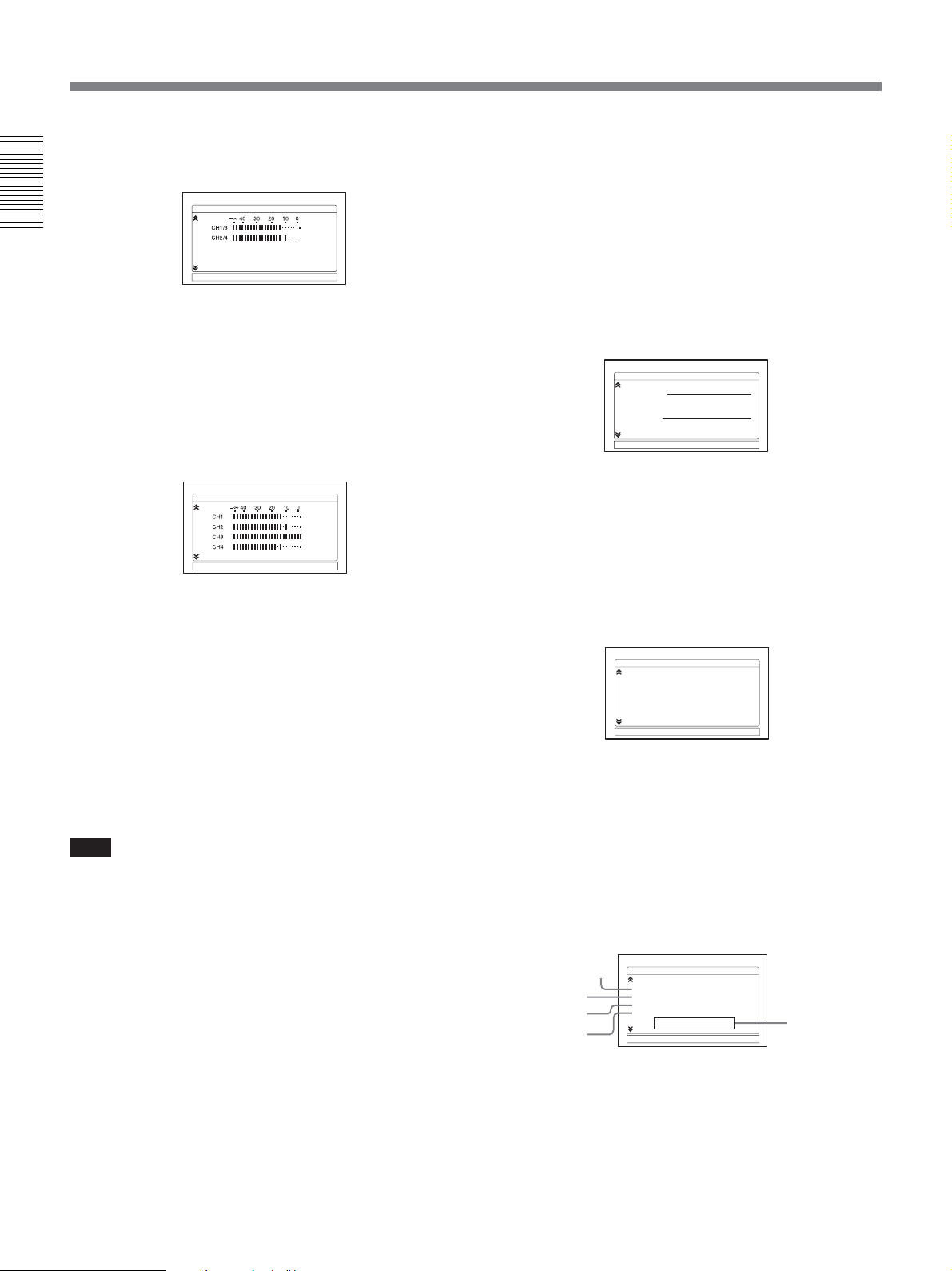
(b) When AUDIO OUTPUT SELECT switch is set to
MIX
Chapter 1 Overview
(The mixed level of channels 1 and 3 is displayed on
CH1/3; that of channels 2 and 4 is displayed on CH2/4.
The audio output level becomes 50% (–6 dB) of the
original audio levels.)
AUDI O
AUDIO MONI:
[
STATUS CHECK] : END
CH1 , CH2
1/4
(c) When the unit is in the audio dubbing mode and
AUDIO OUTPUT SELECT switch is set to CH-1/2
or CH-3/4
AUDIO
AUDIO MONI:
[
STATUS CHECK] : END
CH1 , CH2
(The levels of playback sound are displayed on CH1 and
CH2. The levels of input sound to be dubbed are
displayed on CH3 and CH4. When AUDIO OUTPUT
SELECT switch is set to MIX, the mixed level of the
pair of channels 1 and 3 and that of channels 2 and 4 is
displayed. The audio output level becomes 50% (–6 dB)
of the original audio levels on each channel. In this case,
the meters are as illustrated in (b) on this page. To check
only the sound to be dubbed before dubbing, press
AUDIO DUB button while the unit is in the stop mode.
The level meters fluctuate only when the channels
(channel 3 and 4) are selected for audio dubbing.)
Note
1/4
In EE, recording, or audio dubbing (only the channels
used to dub) mode, if the input levels exceed 0 dB, the
portions of the meters turn red. (However, when the
audio mode is set to 32 kHz (4-channel,12 bits),
whereas AUDIO OUPUT SELECT switch is set to
MIX, the mixed audio levels that exceed 0 dB do not
turn red.) During playback or while HDV/DV signals
are input, the levels meters do not turn red.
OUTPUT screen
OUPUT screen is displayed when STATUS CHECK is
set to [OUTPUT].
You can confirm the setting values of [HDV/DV SEL]
in [IN/OUT REC] menu, [HDMI/CMPNT] and
[DOWN CONVERT] of [VIDEO OUT], and [HDV
t DV CONV] and [DOWN CONVERT] of [i.LINK
SET] in [IN/OUT REC] menu.
For details on OUTPUT settings, see “IN/OUT REC” menu
on page 67.
OUTPUT 2/4
HDV/DV SEL : AUTO
VIDEO OUT
HDMI/CMPNT : 1080i / 480i
DOWN CONVERT : SQUEEZE
i.LINK SET
HDVpDV CONV : OFF
DOWN CONVERT : SQUEEZE
[
STATUS CHECK] : END
ASSIGN screen
ASSIGN screen is displayed when STATUS CHECK
is set to ASSIGN.
You can confirm the setting values of [ASSIGN BTN]
in [OTHERS] menu.
For details on ASSIGN buttons, see “ASSIGN BTN” on
page 77.
ASSIGN 3/4
[A1]
ASSIGN
: INDEX MARK
[A2]
: COUNT. RESET
ASSIGN
[A3]
: AUDIO DUB
ASSIGN
[
STATUS CHECK] : END
CUSTOM REPEAT screen
CUSTOM REPEAT screen is displayed when
STATUS CHEK screen is set to [CUSTOM
REPEAT].
The settings of [CUSTOM REPEAT] in [VTR SET]
menu are displayed. While CUSTOM REPEAT is in
progress, you can also confirm the current status of
CUSTOM REPEAT.
CUSTOM REPEAT 4/4
2
3
4
1
REMAINING : 5h20min
REPEAT TIMES : 07/99
REPEAT CYCLE : 23min/60min
START TIME : 12 : 34
[
STATUS CHECK] : END
2006 5 1 12 : 00 : 00
sc
5
28 Chapter 1 Overview
Page 29

1 REMAININNG : displays the estimated remaining
time of CUSTOM REPEAT.
2 REPEAT TIMES : displays the times that tape
has played, and the total repeat times you have set in
[REPEAT TIMES].
3 REPEAT CYCLE : displays the playback time
and the interval time of the tape which you have set in
[REPEAT CYCLE].
4 START TIME : displays the time CUSTOM
REPEAT starts which you have set in [START TIME].
5 Date and time : displays the date and time set by
[CLOCK SET] in [OTHERS] menu is displayed, when
[START TIME] is set to [ON].
Note
Items that have not been set up are displayed as [OFF].
For details on CUSTOM REPEAT, see “CUSTOM
REPEAT” menu on page 74.
Chapter 1 Overview
Chapter 1 Overview 29
Page 30
Chapter 2 Playback and Recording
Notes on Power Supply and Video Cassettes
Chapter2
Playback and
Recording
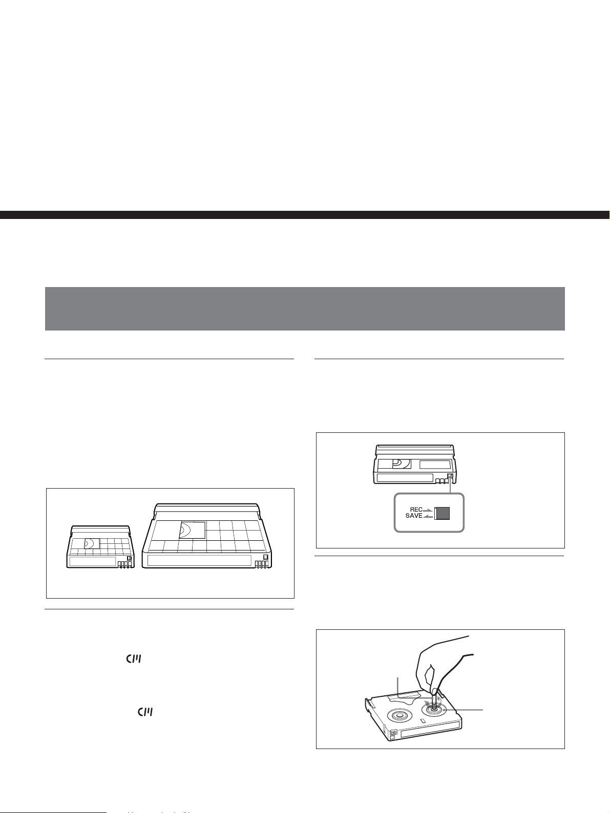
Usable cassettes
We recommend you to use a DigitalMasterTM cassette
of standard HDV/DVCAM/DV cassette (such as
PHDV-276DM), or mini HDV/DVCAM/DV cassette
(PHDVM-63DM) for recording in HDV/DV format.
We recommend you to use a standard DVCAM
cassette, Mini-DVCAM cassette, or DigitalMaster
shown above for recording in DVCAM format.
Mini cassette
Standard cassette
TM
Cassette memory
Some mini cassettes and standard cassettes have the
cassette memory (
not support cassette memory.
However, if you use the DSR-25/45/50 as a recorder,
the unit accesses cassette memory only if the recorder
is set to [AUTO q
mark). The unit, however, does
].
To save a recording
To prevent accidental erasure of a recording, set REC/
SAVE switch on the cassette to SAVE. To record or
dub audio on a tape, set the switch to REC.
Set to SAVE.
REC/SAVE switch
Checking the tape for slack
Using a paper clip or a similar object, turn the reel
gently in the direction shown by the arrow. If the reel
does not move, there is no slack.
Paper clip, etc.
Reel
30 Chapter 2 Playback and Recording
Page 31
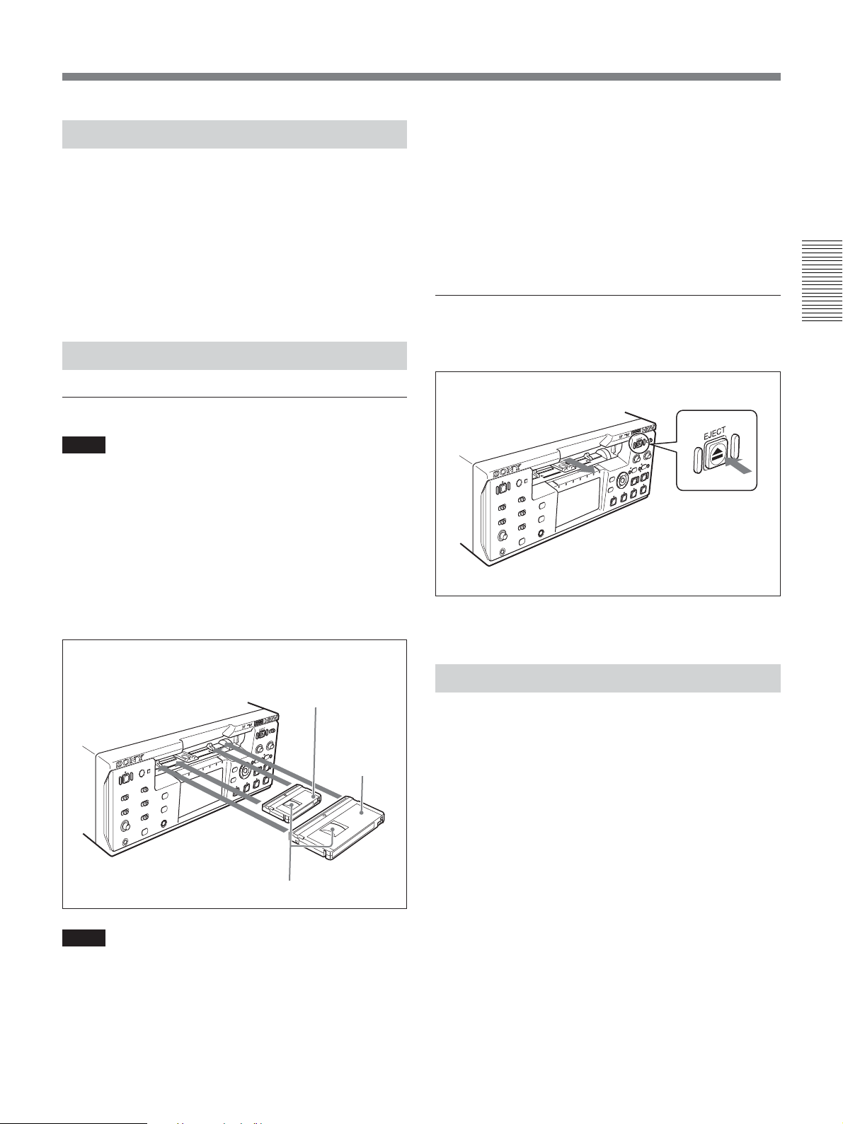
Preparing the Power Supply
Connect the power cord (supplied) to the AC IN
connector. Then, connect the power plug to the wall
outlet.
When you disconnect from the wall outlet, be sure to
unplug the power plug from the wall outlet first.
[CLOCK SET] screen appears when you turn on the
unit for the first time.
For details on [CLOCK SET], see page 78.
Inserting/Ejecting Cassettes
To insert a cassette
Notes
•Do not insert the cassette forcibly. The unit may be
damaged.
•Do not eject/load the cassette in a place subject to
light. The internal sensor of the unit may operate
incorrectly if too much light falls on the unit.
• If the cassette does not load or is loaded only
halfway, eject it once, then insert it again. In such a
case, if you insert the cassette forcibly, the cassette
may not be loaded properly or malfunctions may
occur.
• It takes a few seconds for the unit to recognize the
cassette and find the proper location on the tape being
loaded.
To eject the cassette
Chapter 2 Playback and Recording
With the unit powered on, press EJECT button.
After checking the tape for slack, hold the cassette so
that the tape window is facing upward, then insert it
into the unit.
Mini cassette
(Insert the mini cassette
into the center of the
cassette compartment.)
Standard
cassette
Tape window facing upward
Notes
•When inserting a cassette, hold the back edge of the
cassette in the center and push it until the cassette is
inserted deep into the unit. If you hold the ends, the
cassette may not be loaded properly.
The cassette is unloaded and ejected.
Notes on Playback/Recording
No compensation for contents of the
recording
Contents of the recording cannot be compensated for if
recording or playback is not successful due to a
malfunction of the unit, video tape, etc.
Copyright precautions
Television programs, films, video tapes, and other
materials may be copyrighted. Unauthorized recording
of such materials may be contrary to the copyright
laws.
(Continued)
Chapter 2 Playback and Recording 31
Page 32

Notes on Power Supply and Video Cassettes
On recording
You cannot record or output EE signals and any
software having copyright protection signals on the
unit. If you start recording protected video and audio
signals, a warning appears on the monitor screen and
the unit stops recording.
During recording, do not change INPUT SELECT
switch setting. If you do so, the unit may mistakenly
recognize that copyright control signals has been input.
On playback
Chapter 2 Playback and Recording
When you play back software having copyright
protected signals on the unit, you may not record or
output to other equipment.
Limitations caused by differences in format
The unit can record and play back tapes recorded in
HDV (1080/60i, 1080/50i) or DVCAM format. It can
also record and play back tapes recorded in DV format
(SP mode).
However, due to differences in format, you may not
play back or edit some tapes affected by recording
conditions of the tape (i.e., a tape originally recorded
in DV format is dubbed in DVCAM format).
The unit cannot input/output, record, or play back a
tape other than 1080/60i or 1080/50i format such as
1080/30F, 1080/25F, 1080/24F, 720/25p, 720/24p
format.
The unit cannot input/output, record, or play back a
tape with 4-channel audio signals in HDV extended
format.
You can play back HDV720/30p format, whereas you
cannot output the video signals from
For details, see “Compatibility of HDV, DVCAM, and DV
Formats” on page 93.
HDV/DV jack.
Note on playback on other equipment
A tape recorded in HDV format with the unit cannot be
played back with the devices not compatible with
HDV1080i format. We recommend confirming the
contents of the tape by playing back the tape with the
unit before playing back it on another video
equipment.
If a tape has both a portion recorded in HDV/DVCAM
format and one recorded in DV format (SP mode), the
following limitations are applied when you play back
the tape with the unit:
• The image may be distorted and noise may occur at
the point where the recording format changes on the
tape.
• The tape transport control buttons may be disabled
until the tape speed is stabilized.
32 Chapter 2 Playback and Recording
Page 33
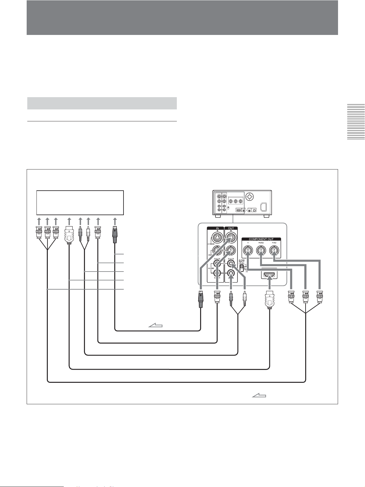
Playback
This section describes the connections and settings for
the playback and functions such as playback at various
speeds and searching for a specific scene on a recorded
tape.
Connections for Playback
Connecting the unit to a monitor without
an i.LINK jack
You can connect the unit to video monitor without an
i.LINK jack. Use the unit as follows.
Chapter 2 Playback and Recording
Monitor
HVR-M25 (rear panel)
S-video input
Video input
Audio input
HDMI input
Component video input
S-video cable (not supplied)
Video cable (not supplied)
Audio cable (Phono jack) (not supplied)
HDMI cable (not supplied)
Component video cable (not supplied)
When an HDMI cable is used for connection, Audio
cable connection is not necessary.
: Signal flow
(Continued)
Chapter 2 Playback and Recording 33
Page 34
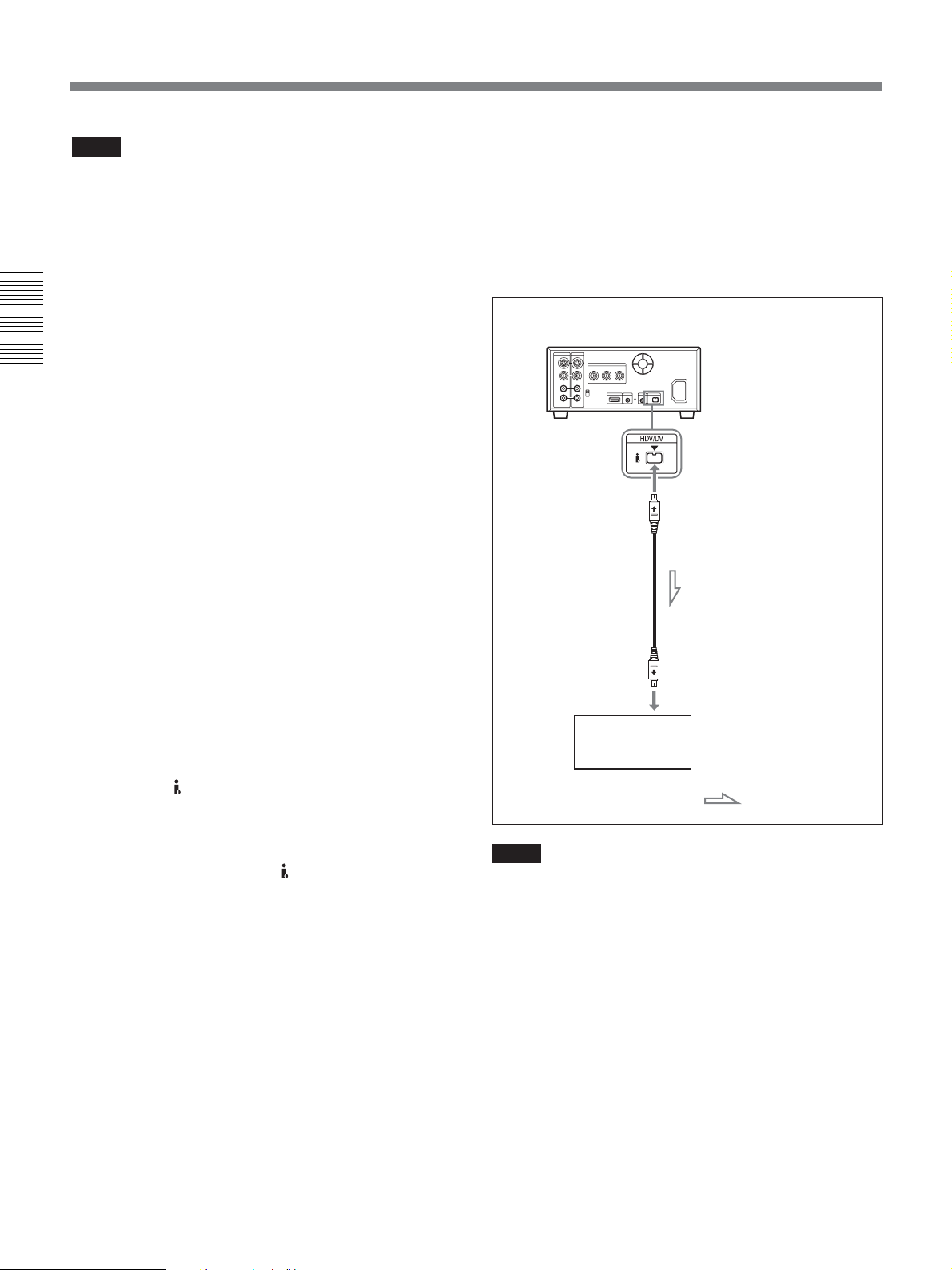
Playback
Notes
• To playback the picture recorded in HDV format
when you connect the monitor using an HDMI cable
or a component video cable, set [HDMI/CMPNT] of
[VIDEO OUT] in [IN/OUT REC] menu according to
your monitor (page 68). When the picture recorded in
DVCAM/DV format is played back, only a picture
with a quality equivalent with DVCAM/DV format of
480i (NTSC) or 576i (PAL) is output via
COMPONENT OUT jacks regardless of [HDMI/
Chapter 2 Playback and Recording
CMPNT] setting.
• For details on output level from HDMI OUT jack and
COMPONENT OUT jacks, see “Specifications”
(page 100).
• To change the output level from COMPONENT OUT
jacks, see [480i LEVEL] in [IN/OUT REC] menu
(page 71)
.
• There are some restrictions on pictures output from
HDMI OUT jack and COMPONENT OUT jacks of
the unit.
Refer to HDMI OUT jack 6, COMPONENT OUT jacks
5 in “Rear Panel” of the “Location and Function of
Parts” on page 19.
• If you connect the input connectors of the unit to the
output connectors of a monitor, a humming noise
may be generated or the image may be distorted. If
these phenomena occur, use INPUT SELECT switch
to select a signal that is not being input or disconnect
the cables.
• When you play back a tape with copyright protected
signals or input HDV signals with copyright
protection to
HDV/DV jack, pictures and audio are
not output via HDMI OUT jack.
• When you play back an HDV-formatted tape with
copyright protected signals or input i.LINK signals
with copyright protection to
HDV/DV jack, pictures
may be output in either 480i (NTSC) or 576i (PAL)
format regardless of the setting of [HDMI/CMPNT]
of [VIDEO OUT] in [IN/OUT REC] menu.
• The unit cannot up convert DVCAM/DV recordings
to HDV at output.
Connecting the unit to a monitor equipped
with an i.LINK jack
The video and audio signals are sent with hardly any
degradation, enabling high-quality playback to a
monitor with an i.LINK connector which supports
HDV, DVCAM, and DV format.
HVR-M25 (rear panel)
i.LINK cable (not supplied)
i.LINK jack
Monitor with an
i.LINK jack
: Signal flow
Notes
•Be sure that you set [HDV/DV SEL] in [IN/OUT
REC] menu to [AUTO] (default setting) before
connecting the monitor to the unit with the i.LINK
cable. If you change the setting after connecting the
i.LINK cable, the monitor may not recognize the
video signals correctly (page 67).
• To connect the unit to a monitor equipped with an
i.LINK jack, you may need to set the monitor so that
it recognizes the unit.
For details, refer to your monitor’s instruction manual.
•When i.LINK is connected, the unit cannot output
video or audio only.
34 Chapter 2 Playback and Recording
Page 35

• If you connect the input connectors of the unit to the
output connectors of a monitor, a humming noise
may be generated or the image may be distorted. If
these phenomena occur, use INPUT SELECT switch
to select signals that is not being input or disconnect
the cables.
• To connect the i.LINK cable between a monitor and
the unit, use an HDV or DV-compatible monitor. To
play back a tape recorded in the HDV mode on a DVcompatible monitor, set [HDV t DV CONV] of
[i.LINK SET] in [IN/OUT REC] menu to [DVCAM]
or [DV SP] before connecting the unit with the
i.LINK cable.
For details, refer to your monitor’s instruction manual.
• Some general consumer television sets are provided
with a function to control equipment connected with
the i.LINK cable. Such a function, however, may not
work with the unit.
Settings for Playback
Preparation on the unit
Notes
• Text information is superimposed to VIDEO OUT
jack, S VIDEO OUT jack, COMPONENT OUT
jacks, and HDMI OUT jack. To output video signals
without text data, set DISPLAY OUTPUT switch to
OFF.
For details on DISPLAY OUTPUT switch, see page 11.
For details on text data, see “Displaying Various Data”
on page 25.
• To view a tape recorded in HDV format by
connecting the unit to a monitor set that has a 4:3
aspect ratio, set [DOWN CONVERT] of [VIDEO
OUT] in [IN/OUT REC] menu to the desired mode
(page 68).
Playback Procedures
1 Insert a cassette and confirm that q (cassette)
indicator lights.
2 Press PLAY button on the unit.
The unit starts playback.
To stop playback
Press STOP button on the unit.
To pause playback
Press PAUSE button on the unit.
Notes
• If the unit is playing a portion of a tape where the
recording format changes between HDV, DVCAM,
and DV, the picture and sound are distorted on such
portions.
•You cannot play back an image recorded in DV (LP)
mode on the unit.
• If the unit is playing a tape recorded with mixed
video signals of the 60i system and 50i system, the
picture and sound will be distorted on a portion of a
tape where the recording system changes.
•During pause, the picture recorded on a tape in HDV
format cannot be output from
HDV/DV jack.
Chapter 2 Playback and Recording
1 Power on the monitor, then set the monitor’s input
switch according to the signals input.
2 Turn the unit on.
Chapter 2 Playback and Recording 35
Page 36
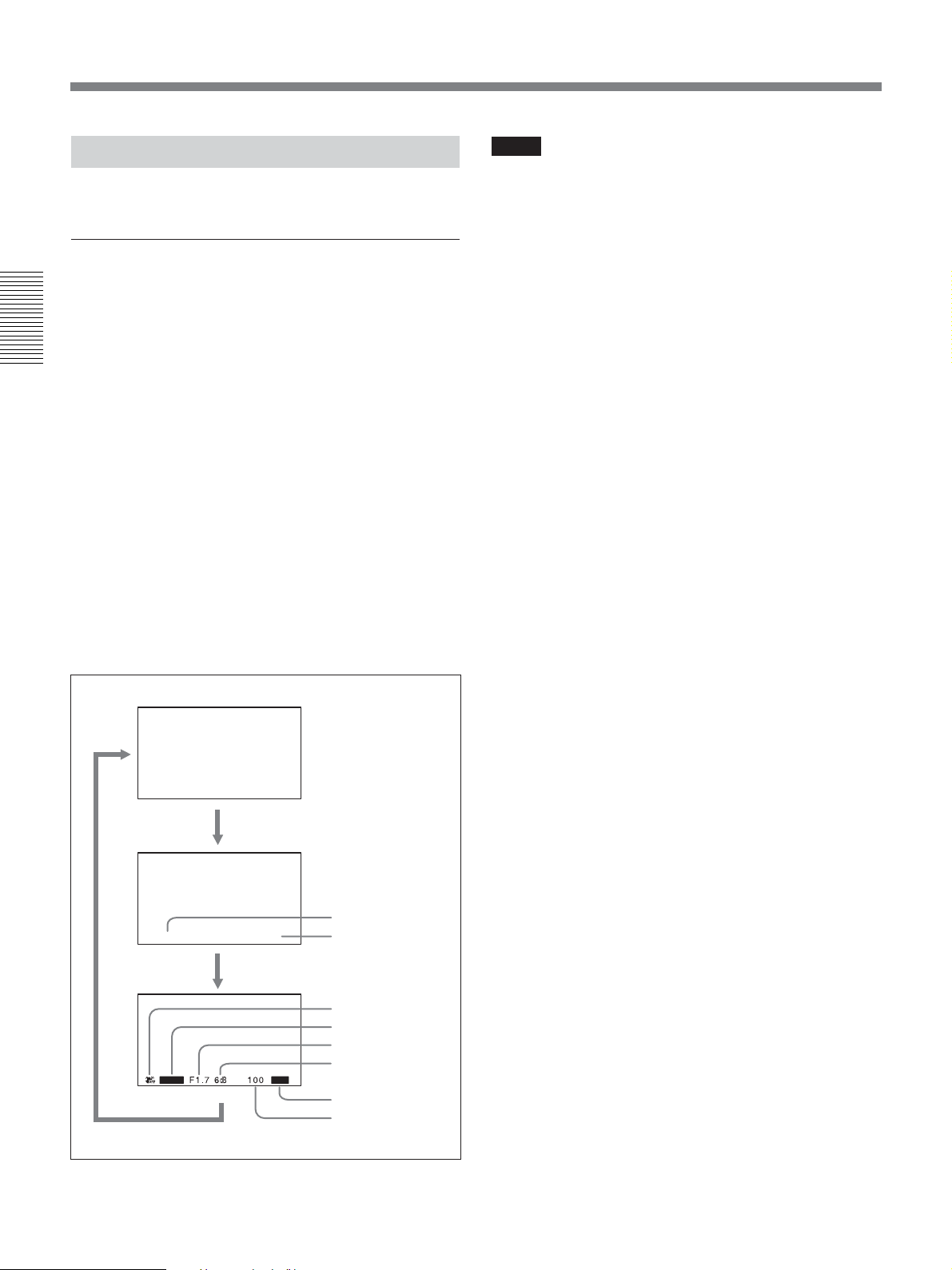
Playback
Playback Functions
This section describes useful functions during
playback.
Displaying information (data codes)
recorded on a tape
If you record on a tape using a Sony digital HD video
camera recorder or digital camcorder, the recording
information (data codes) is recorded on the tape.
Chapter 2 Playback and Recording
The data codes consist of recording date/time and
camera data (the shutter speed, SteadyShot, iris, white
balance, program AE mode, gain, date and time).
You can check these data items during playback on the
unit.
Each time you press DATA CODE button on Remote
Commander, the display changes in sequence as
follows:
no data code t recording date/time t camera data
t no data code ..... Also, you can change the display
by setting [DATE] or [CAMERA DATA] of [DATA
CODE] in [DISPLAY SET] menu.
For details, see “DATA CODE” on page 72.
Notes
• If data codes were not recorded, “- - -” appears
instead.
• The unit cannot record camera data.
• Some of the camera data items displayed by the unit
are different from those shown on the digital
camcorder and digital HD video camera recorder.
No indicator
Recording
date/time
2006 1 1 19 : 20 : 30
Camera
data
AUTO
AUTO
Date
Time
SteadyShot
Program AE
Iris
Gain
ATW
White balance
Shutter speed
36 Chapter 2 Playback and Recording
Page 37
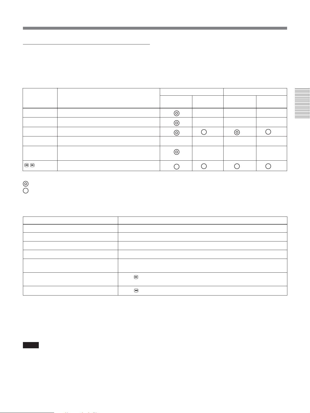
Playing at various speeds
You can playback a tape at various speeds using
Remote Commander.
HDV-formatted tape
Button
× 1/10
× 1/3
× 1
× 2
FRAME
c/C
Operation speed
One-tenth of normal speed
One-fifth of normal speed
Playback at normal speed
Playback at normal speed
Frame-by-frame forward scanning
Panel/analog output
Forward
direction
—*
Reverse
direction
—*
—*
—*
—*
i.LINK output
Forward
direction
—
—
—*
—
Reverse
direction
—*
—*
—*
—*
Chapter 2 Playback and Recording
/
8× speed
* The output will be the same as that of ×1.
: Play at normal speed.
: A search simple image is output. (Rough image)
— : No playback takes place.
DVCAM/DV-formatted tape
Playback options
Play at 1/10 of normal speed
Play at 1/3 of normal speed
Play at normal speed Press × 1 button during playback.
Play at twice the normal speed
Play frame by frame
Fast forward the tape while monitoring
pictures
Rewind the tape while monitoring pictures Press button during normal playback or when playing at various speeds.
To change playback direction
Press FRAME c/C buttons during normal
playback or when playing at various speeds. To play
back in the forward direction, press C button; in the
backward direction, press c button.
Operation
Press × 1/10 button during playback.
Press × 1/3 button during playback.
Press × 2 button during playback.
Press FRAME c/C buttons during pause.
If you keep pressing one of these buttons, playback continues, frame by frame.
Press
button during normal playback or when playing at various speeds.
–when you playback a tape in DVCAM/DV format
and press ×1/5 button on Remote Commander
while pointing it toward the unit, the playback
speed turns to 1/3 of normal speed.
• If the unit keeps playing at 1/10 of normal speed in
forward or reverse for more than 1 minute, the unit
Notes
begins to play back at normal speed.
•When the command mode of a Sony device/remote
commander is set to VTR4:
– if you press ×1/3 button on the supplied Remote
Commander while pointing it toward a Sony device
other than the unit, the playback speed may turn to
1/5 of normal speed.
Chapter 2 Playback and Recording 37
Page 38
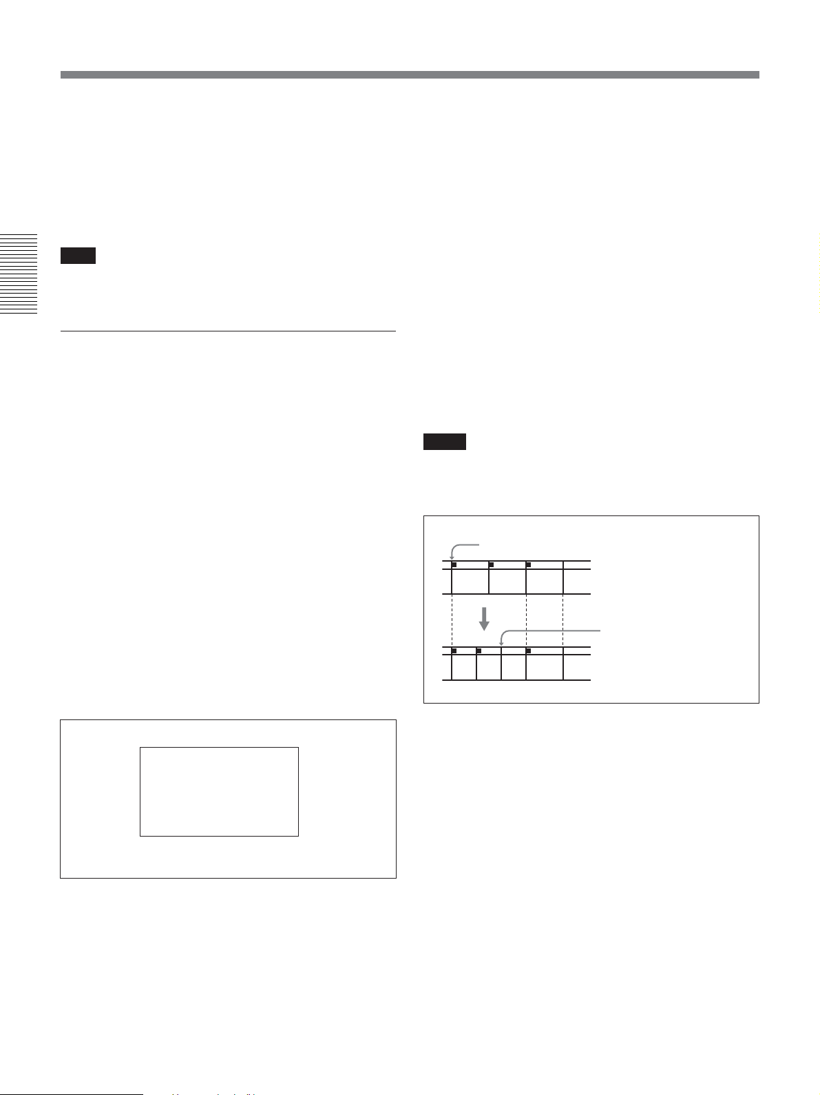
Playback
To hear the sound while playing at various
speeds
To hear the sound when playing at various speeds, set
[JOG AUDIO] in [AUDIO SET] menu to [ON].
For details on [AUDIO SET] menu, see “AUDIO SET”
menu on page 73.
Note
You cannot hear the sound while playing back a tape
recorded in HDV format at various speeds.
Chapter 2 Playback and Recording
Searching using the search function
The unit can immediately access the following signals
recorded on a tape.
– Searching for the beginnings of the recordings:
Index search
– Searching for a point on the tape where the
recorded date changes: Date search
To search for scenes, use the supplied Remote
Commander. Also, you can assign the same search
function to ASSIGN buttons.
For details on ASSIGN buttons, see “ASSIGN BTN” in
“OTHERS” menu on page 77.
2 Press . / > button repeatedly to locate the
scene you want.
Each time you press . / > button, the unit
searches for the previous or next search point.
When a search point is located, its number is
indicated on the monitor screen.
The unit starts searching backwards or forwards
until the number comes to zero, then plays back the
scene.
How signals are recorded
There are four different signal types, one for each
search method; index, title, date and photo signals. The
unit can record either index signals or date signals only
on a tape.
Notes
• If you record another program over the beginning of
the search signals, you cannot locate the original
program.
Search signal
If D is recorded over the
ABC
beginning of B...
1 Press SEARCH SELECT button on Remote
Commander to select the search type.
The search type changes in the order of Index
search t Date search t (No indication).
When selecting INDEX SEARCH
(The search screens are displayed only on
Data display screen.)
INDEX 00
SEARCH
B cannot be searched for
CADB
• The interval of a date or index must be 2 minutes or
more. If the interval is short, the search signals may
not be detected correctly.
• If non-recorded portions are included in the middle of
a tape, signal search may not be performed correctly.
•You cannot add search signals after recording.
• The unit does not support searching, reading or
writing of data on cassette memory. For duplicating
with the DSR-25/45/50, see page 30.
• Searching may not be done correctly if the tapes were
not recorded on Sony-brand digital video equipment.
38 Chapter 2 Playback and Recording
Page 39
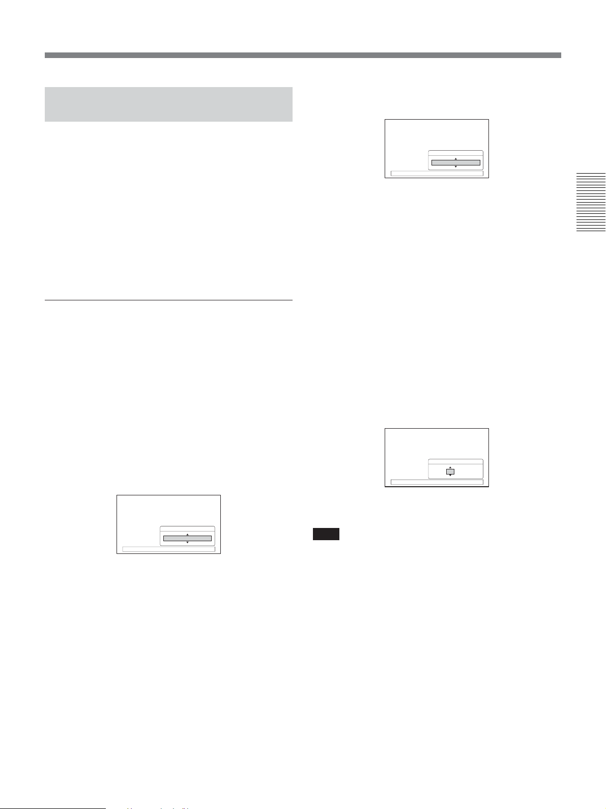
AUTO REPEAT (CUSTOM REPEAT)
The unit can repeat playback of all or a part of a tape.
When the following items on the tape are searched,
AUTO REPEAT playback starts automatically.
– Index signals
–A portion unrecorded
–A portion recorded in the format set by other than
[AUTO] in [HDV/DV SEL] in [IN/OUT REC] menu
– Tape end
By setting up [CUSTOM REPEAT] in [VTR SET]
menu, you can customize the repeat times, the repeat
cycle, and the start time of repeat playbacks.
To set the CUSTOM REPEAT
Set the following sub menus of [CUSTOM REPEAT]
in [VTR SET] menu.
REPEAT TIMES
ON/OFF : Selects either to enable or to disable
REPEAT TIMES setting.
TIMES : Sets the number of times to repeat
playback.
Set the desired number by pressing J/j button on the
unit.
REPEAT CYCLE
CYCLE
60min
[
MENU] : END
Press EXEC button to complete.
To play back at START TIME, rewind a tape
beforehand. If the tape is not rewound, the unit
rewinds the tape to its beginning at selected START
TIME, then start playback.
START TIME
ON/OFF : Selects either enable or disable [START
TIME].
TIME : Sets the start time of [CUSTOM REPEAT].
You can adjust the start time of [CUSTOM REPEAT].
Set the number of each hour and minute by pressing
J/j button on the unit.
Press EXEC button after the hour is set, then adjust the
minute.
START TIME
Chapter 2 Playback and Recording
Repeat times can be set from 1 to 99 times.
Set the number of repeat times by pressing J/j
buttons on the unit.
REPEAT TIMES
TIMES
45
[
MENU] : END
Press EXEC button to complete.
REPEAT CYCLE
ON/OFF : Selects either enable or disable the
REPEAT CYCLE setting.
CYCLE: Sets the time of intervals for playback.
Time of repeat interval is equal with the total time of
tape in playback, rewind, and stop.
Repeat intervals can be selected from 15 minutes to
300 minutes with 5 minutes increment.
TIME
12 : 30
[
MENU] : END
Press EXEC button to complete.
Note
While the unit is in STANDBY mode, even when
START TIME setting is applied and the start time
comes, the unit will not power on automatically.
For details on “CUSTOM REPEAT”, see page 74.
Also, refer to “TIMER switch” (page 10), “STATUS
CHECK screen” (page 27), and “CUSTOM REPEAT
screen” (page 28).
Chapter 2 Playback and Recording 39
Page 40
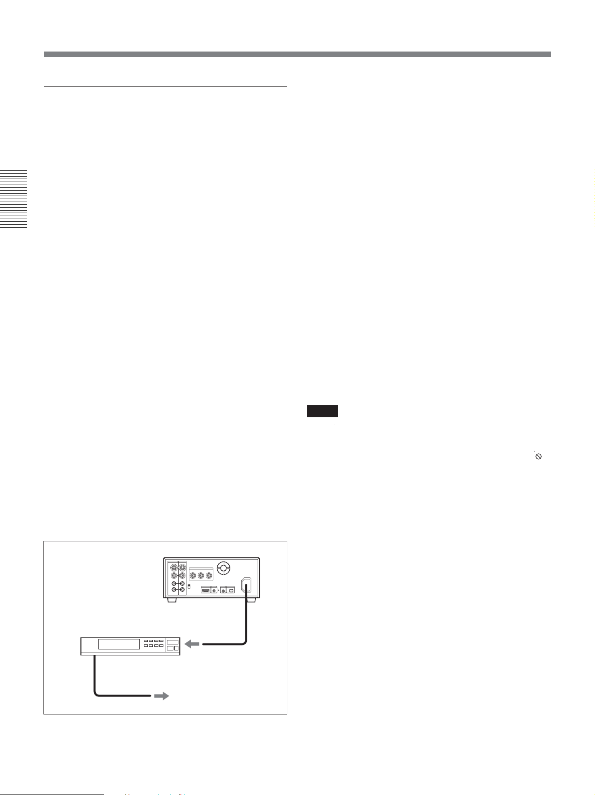
Playback
Setting the AUTO REPEAT
If [START TIME] is set to [OFF]
1 Set TIMER switch to REPEAT.
is displayed on Data display screen (page 25).
s
2 Press REW button. (If the tape is already rewound,
press PLAY button.)
Chapter 2 Playback and Recording
The unit rewinds the tape to its beginning and
starts playback automatically.
When the following items on the tape are searched,
AUTO REPEAT playback starts automatically.
– Index signals
–A portion unrecorded
–A portion recorded in the format set by other
than [AUTO] in [HDV/DV SEL] in [IN/OUT
REC] menu
– Tape end
When [REPEAT CYCLE] is set, the unit continues
playback until a few minutes before the time
reaches at the actual selected time, or the items
listed above is detected on a tape. The tape is
rewound to the beginning and restarts playback
when the selected CYCLE time comes.
If you set [REPEAT TIMES], the unit repeats
playback according to the times you have selected.
Auto Repeat using an external AC timer
1 Connect the unit to an external AC timer (not
supplied).
HVR-25M
(rear panel)
2 Set the TIMER switch on the front panel of the
unit to REPEAT.
3 Set the start time on the external AC timer.
At the preset time, the power of the unit turns on,
and after a few to several ten seconds, AUTO
REPEAT playback starts automatically. When the
following items on the tape are searched, AUTO
REPEAT playback starts automatically.
– Index signals
–A portion unrecorded
–A portion recorded in the format set by other
than [AUTO] in [HDV/DV SEL] in [IN/OUT
REC] menu
– Tape end
If [START TIME] is set to [ON]
Set TIMER switch to [REPEAT].
When the unit is powered on, the unit waits the repeat
playback until the time you have set in [START
TIME]. Also, when TIMER switch is set to REPEAT
and the unit is powered on, auto playback is set to
standby until the start time begins.
Notes
•
• To operate AUTO REPEAT automatically, the tape
•When [START TIME] for [CUSTOM REPEAT] is
To stop the AUTO REPEAT while the unit is in
progress
Press STOP button on the front panel.
is displayed on Data display screen. When the
sc
tape on the unit is not in the playback mode, such as
during recording or when no tape is inserted,
is displayed. When the start time reaches the selected
time during this time, auto playback is not operated
until the next starts time begins.
should be stopped before the start time begins.
set, turn the unit on before the actual start time
begins.
sc
AC timer
to an AC outlet
40 Chapter 2 Playback and Recording
When both [REPEAT TIMES] and [START TIME]
are set, if you stop AUTO REPEAT, the unit waits for
the START TIME to come, regardless of the REPEAT
TIMES setting. When the start time comes, the value
of REPEAT TIMES is initialized to zero, and repeat
playback starts.
Page 41
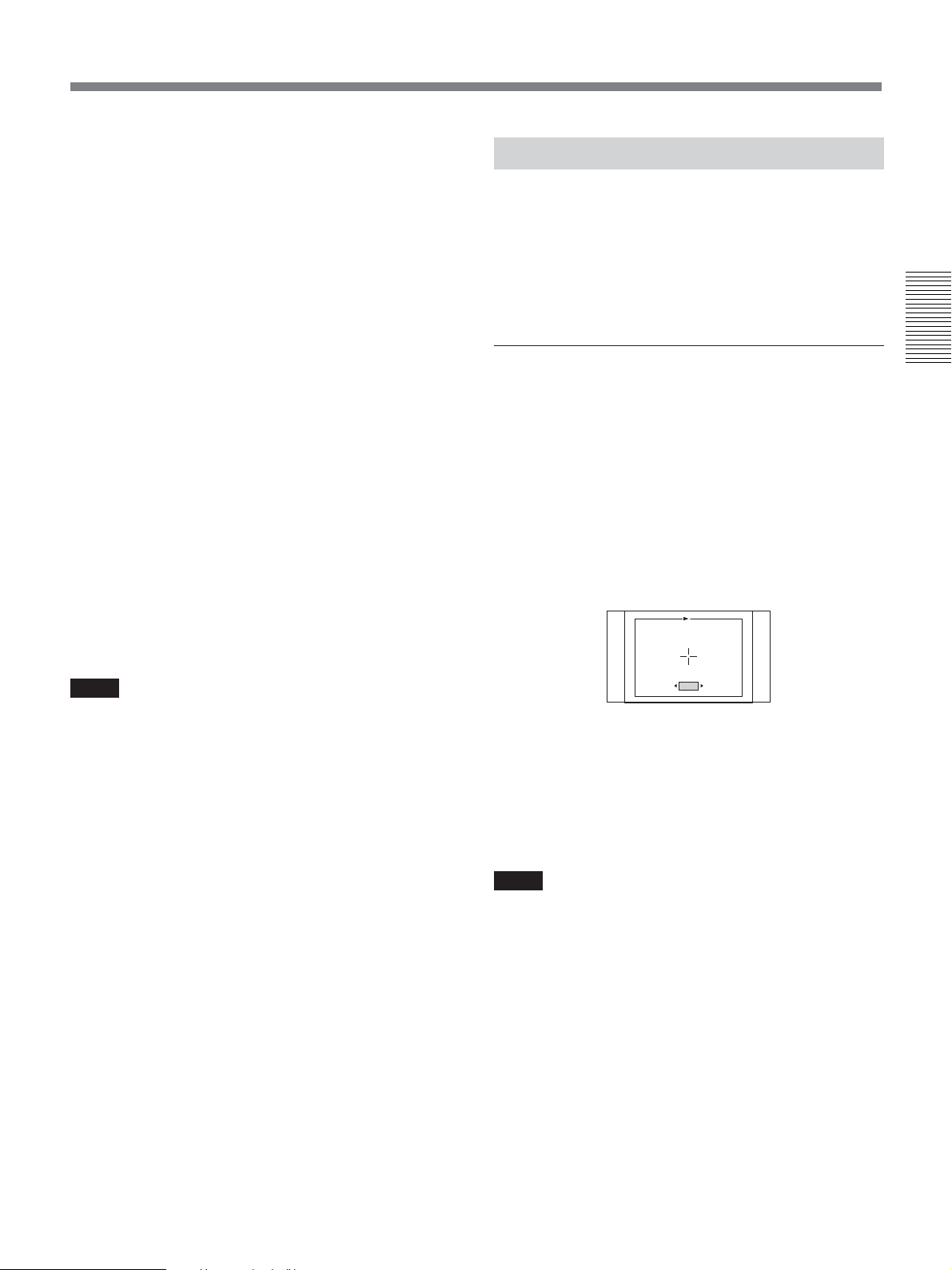
To cancel the AUTO REPEAT
CROP ADJUST
MENU
: END
Set TIMER switch to OFF.
EDGE CROP MARKER
By using AUTO REPEAT, you can do the
following as examples
Repeat playbacks with 30 minutes interval :
1 Set [ON/OFF] of [REPEAT CYCLE] to [ON].
2 Set [CYCLE] of [REPEAT CYCLE] to [30 min].
3 Press REW or PLAY button.
Repeat playbacks 5 times for 2 hours per day at 9
a.m. :
1 Set [ON/OFF] of [REPEAT CYCLE] to [ON].
2 Set [CYCLE] of [REPEAT CYCLE] to [120 min].
3 Set [ON/OFF] of [REPEAT TIMES] to [ON].
4 Set [TIMES] of [REPEAT TIMES] to [5].
5 Set [ON/OFF] of [START TIME] to [ON].
6 Set [TIME] of [START TIME] at [9:00].
7 Turn the unit on before 9 a.m.
The unit allows you to adjust the edge crop position
when you output the down converted HDV 16:9 wide
screen pictures to 4:3 standard TV mode pictures. By
displaying the edge crop marker on the monitor, you
can check the crop position on LCD monitor
beforehand.
To set EDGE CROP MARKER
Either set [CROP MARKER] in [IN/OUT REC] menu
to [ON] after setting [DOWN CONVERT] of [VIDEO
OUT] in [IN/OUT REC] menu to [EDGE CROP] or
[DOWN CONVERT] of [i.LINK SET] in [IN/OUT
REC] to [EDGE CROP].
EDGE CROP MARKER screen displays;
• Crop position of 4:3 aspect screen
• Center marker
• 80% safety zone
CROP ADJUST
CROP ADJUST
Chapter 2 Playback and Recording
Notes
• The unit cannot detect signals for Index signal, a
signal other than the one set by [AUTO] in [HDV/DV
SEL], or an unrecorded portion within 20 seconds of
the beginning of the playback.
•When you intend to turn the unit off, press STOP
button on the unit to stop the tape transport operation
beforehand. If you turn the unit off while a tape is
running, for example, by using an AC timer, the unit
or the tape may be damaged.
• The editing software used on the digital non-linear
editing system may mark index signals on a tape
itself. Therefore, if you use a tape on which signals
transmitted from a digital non-linear editing
controller are recorded or a copy tape made from one,
using digital dubbing, Auto Repeat may not be
performed correctly.
]
: END
+2
[
[
MENU
MENU] : END
Select [CROP ADJUST] in [IN/OUT REC] menu and
press EXEC button again after the confirmation
display appears. Then, EDGE CROP MARKER will
appear on the monitor. Press K/k buttons to move
the marker to the left and right and adjust the position
to crop. Press EXEC button to execute.
Notes
•When CROP MARKER is displayed on LCD
monitor, the text data and crop marker displayed on
LCD monitor are not output from jacks on the rear
panel of the unit. To output 4:3 screen marker, see
[MARKER BURN].
• To output an edge cropped picture by down
converting the HDV-formatted picture to 4:3, see
“VIDEO OUT” (page 68) and “i.LINK SET” (page
69) in “IN/OUT REC” menu.
Chapter 2 Playback and Recording 41
Page 42

Playback
MARKER BURN
The unit can output to each video jacks and display 4:3
screen marker on the 16:9 screen images. In case of
making an editing tape from the original tape,
[MARKER BURN] can be used.
To set up MARKER BURN
Set [MARKER BURN] in [DISPLAY SET] menu to
Chapter 2 Playback and Recording
[ON].
Notes
• MARKER BURN is effective under the following
conditions.
–While playing back a tape in HDV or an HDV
signal is input via
CONVERT] of [VIDEO OUT] in [IN/OUT REC]
menu is set to [SQUEEZE] or [LETTER BOX].
–When wide signals recorded in DVCAM or DV
format are played back, or wide screen HDV/
DVCAM/DV signals are input to each VIDEO
jacks.
•When [DOWN CONVERT] of [VIDEO OUT] in
[IN/OUT REC] is set to [EDGE CROP], the marker
can not be displayed.
• The markers displayed with EDGE CROP and
MARKER BURN show the available horizontal ratio
range of the 4:3 screen to be cropped. The
displayable image size of the standard 4:3 TV
monitor may appear smaller than the size marked on
the monitor of the unit.
•When the EDGE CROP MARKER and MARKER
BURN are enabled at the same time, the EDGE
CROP MARKER is displayed as priority.
• When you set [MARKER BURN] and [ALLSCAN
MODE] in [DISPLAY SET] menu to [ON] at the
same time, the marker will not appear in the correct
position on LCD monitor. This is not a malfunction.
The marker will be output correctly via each video
jack.
HDV/DV jack, and [DOWN
42 Chapter 2 Playback and Recording
Page 43
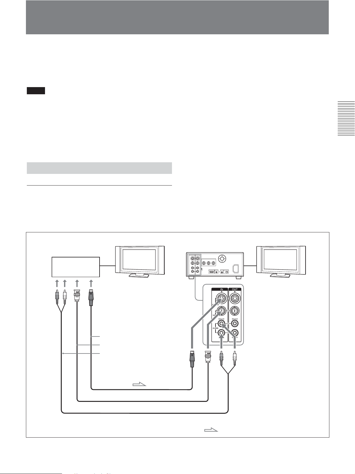
Using the Unit as a Videocassette Recorder
This section describes the connections, settings and
operations necessary to perform recording on the unit.
The same settings and operations apply whether you
are using the unit for dubbing.
Notes
• For connection of the editing devices, refer to the
instruction manual of the editing controller and that
of the editing software you use.
• Edit functions are specified by the editing software.
For details on the editing methods, refer to the
instruction manual of the editing software.
For details, see also page 62 and 63.
Connections for Recording
To video equipment without an i.LINK jack
Chapter 2 Playback and Recording
You can connect the unit to video equipment without
an i.LINK jack. Use the unit as a recorder as follows.
Monitor
Player
S-video output
Video output
Audio output
HVR-M25
(rear panel)
Monitor
S-video cable (not supplied)
Video cable (not supplied)
Audio cable (phono jack) (not supplied)
Connect either an S-video cable or a video cable.
: Signal flow
(Continued)
Chapter 2 Playback and Recording 43
Page 44
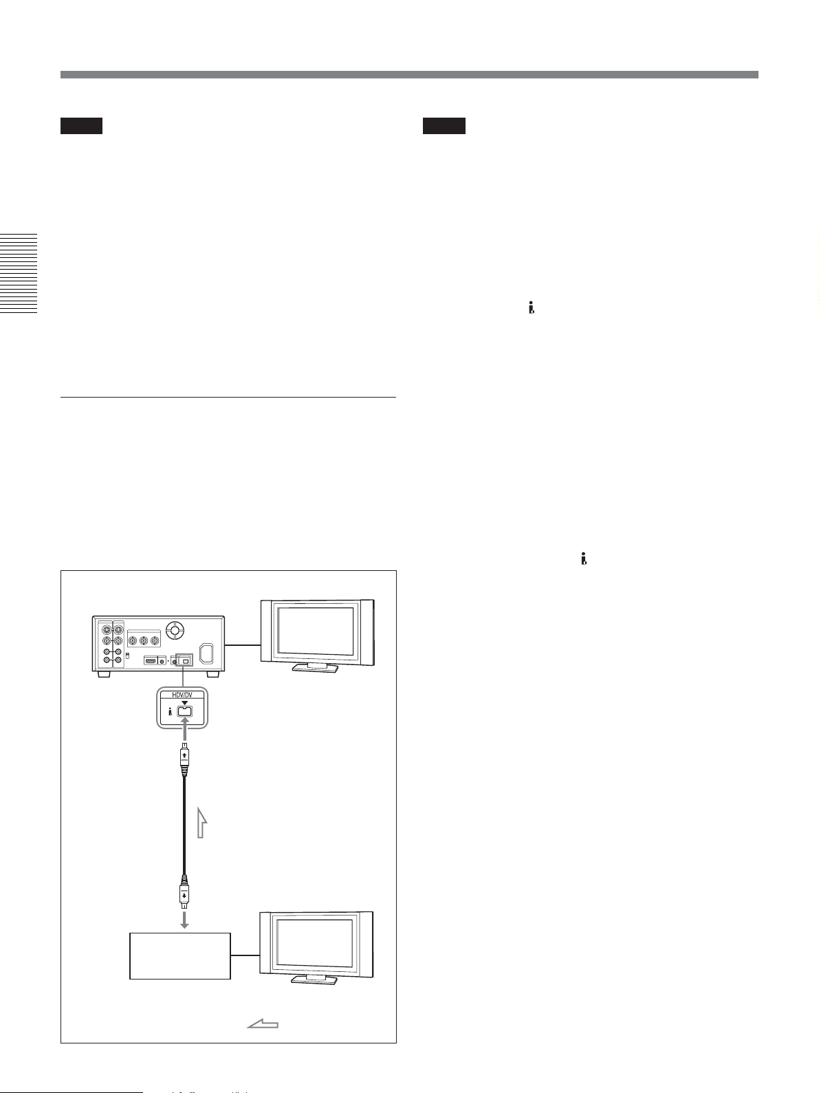
Using the Unit as a Videocassette Recorder
Notes
• If you connect the output connectors of the unit to the
input connectors of the player, a humming noise may
be generated or the image may be distorted. If these
phenomena occur, set INPUT SELECT switch to a
position where a signal is not currently being input,
or disconnect the cables.
•Distorted signals (i.e., when played back at a speed
other than normal) may not be recorded or may be
distorted.
•When you connect only AUDIO IN jacks when HDV
Chapter 2 Playback and Recording
indicator is lit, no audio is input. You must connect
VIDEO IN jack at the same time or set [HDV/DV
SEL] in [IN/OUT REC] menu to [DV].
To digital video equipment with an i.LINK
jack
When you record i.LINK signal of HDV (1080/60i,
1080/50i), DVCAM, or DV format, the video and
audio signals are sent without any degradation in
quality, enabling high-quality recording. The signal
flow is automatically detected so you do not need to
make separate connections for input and output.
Monitor
HVR-M25 (rear panel)
i.LINK cable (not supplied)
i.LINK jack
Digital video equipment
with an i.LINK jack
Monitor
: Signal flow
Notes
•When you record video from HDV-compatible
equipment, set [HDV/DV SEL] in [IN/OUT REC]
menu to [AUTO]. To record video from a DVCAM/
DV equipment, set [HDV/DV SEL] in [IN/OUT
REC] menu to [AUTO] or [DV] before connecting
the i.LINK cable (page 67). If you change the setting
after connecting i.LINK cable, the video equipment
may not recognize the video signals correctly.
•Copy-protected program such as digital broadcast can
not be input via
HDV/DV jack.
•With HDV/DV connection, the sound is recorded in
the same audio recording mode as that of the source
tape. To record in a different audio recording mode
from the source tape, connect as shown in “To video
equipment without an i.LINK jack” on page 43.
•With HDV/DV connection, data codes (recording
date/time, camera data) recorded on the source tape
are transmitted to the recorder (the unit). As a result,
when you play back a recorded tape on the unit and
press DATA CODE button on the Remote
Commander, the same data codes as those recorded
on the source tape are displayed on the monitor
screen.
• If no picture appears via
HDV/DV jack, disconnect
the i.LINK cable, then reconnect it.
• The unit cannot record video or audio separately.
• If you record a picture in DVCAM/DV in the
playback pause mode, the picture may be rough.
When set to HDV, the picture is not recorded.
•When connecting a device that has a 6-pin i.LINK
jack to the unit, first, connect the plug of the cable to
the 6-pin i.LINK jack.
• If the unit is connected to a device equipped with an
i.LINK jack, when you intend to disconnect or
reconnect the i.LINK cable, turn off the device and
pull out the plug of its power cord from the AC outlet
beforehand. If you connect or disconnect the i.LINK
cable while the device is connected to the AC outlet,
high-voltage current (8 to 40 V) is output from the
i.LINK jack of the device to the unit, which may
cause a malfunction.
• If you restart recording after a pause or stop, the
images recorded before and after restarting operation
will not be continuous.
• If you connect the output connectors of the unit to the
input connectors of a player or that of a monitor, a
humming noise may be generated or the image may
be distorted. If these phenomena occur, use INPUT
SELECT switch to select a signal that is not being
input or disconnect the cables.
44 Chapter 2 Playback and Recording
Page 45

• The unit cannot record MPEG2 signals except
HDV1080i signals.
•When you record HDV signals input from
DV jack, the connection between the recorded signals
pause for a second.
HDV/
Settings for Recording
Preparation on the recorder (the unit)
Notes
• Before recording, set the date and time on the unit so
that the recording time can be written into the search
signal. You can set the date and time by setting
[CLOCK SET] in [OTHERS] menu. (page 78)
• Editing may not be possible with a signal that is
copyright protected.
•During recording, the tape transport control buttons
(except STOP and PAUSE) are disabled to prevent
the tape running mode from being changed by an
incorrect operation. To disable STOP and PAUSE
buttons, set KEY INH switch to ON after the unit
starts recording. In this case, set KEY INH switch to
OFF first, then stop or pause the recording.
1 Turn the power on the monitor, then set the
monitor’s input according to the input signals.
Chapter 2 Playback and Recording
2 Set up the player to play back a tape.
For details, refer to the instruction manual of the
player.
3 Turn the unit on.
4 When the player is connected to IN jacks on the
unit, set [60i/50i SEL] in [OTHERS] menu
according to the input signals.
When you input 60i system signals, set [60i/50i
SEL] to [60i]. When you input 50i system signals,
set [60i/50i SEL] to [50i]. (page 79)
Notes
•Do not change [60i/50i SEL] setting during
recording.
•When you select S VIDEO or VIDEO with INPUT
SELECT switch, if the field frequency of the input
signals is different from that of [60i/50i SEL] setting,
the picture mutes.
(Continued)
Chapter 2 Playback and Recording 45
Page 46

Using the Unit as a Videocassette Recorder
•When the signals are input through the i.LINK
interface, the unit detects the field frequency of the
input signal automatically. You do not need to
change [60i/50i SEL] setting. When [60i/50i SEL] is
set to [50i], however, the time code generated by the
unit is fixed to the non-drop frame mode. Even when
60i system signals are input to the i.LINK jack, the
time code generated by the unit is the non-drop frame
mode, regardless of [TC FORMAT] setting in [TC/
UB SET] menu. To record in the drop frame mode,
set [60i/50i SEL] to [60i].
Chapter 2 Playback and Recording
5 Select input signals by switching INPUT SELECT
switch on the unit.
HDV/DV: to record input signals from
jack
S VIDEO: to record input signals from S VIDEO
IN jack
VIDEO: to record input signals from VIDEO IN
jack
You need to adjust [HDV/DV SEL] (page 67) and
[
REC MODE] (page 67) in [IN/OUT REC]
menu to your desirable recording format.
For details on recording tape format, see page 97.
Note
Do not change INPUT SELECT switch setting during
recording. If you change the setting of this switch
during the recording, the recording will stop for
several seconds. Recording will restart after the
internal circuits are switched. During this time, no
image is recorded.
6 Select the audio mode. (With an HDV/DV
connection, skip this step.)
When you select S VIDEO or VIDEO with INPUT
SELECT switch, set the audio mode by setting
[AUDIO MODE] in [AUDIO SET] menu (page
73).
FS32K: Switches the audio mode to 4-channel
mode
FS48K: Switches the audio mode to 2-channel
mode
HDV/DV
Note
When signals are input from HDV/DV jack, the
audio mode is the same as the one to input signals
from the player.
To dub audio after recording, see page 60.
7 Set AUDIO INPUT LEVEL switch on the rear
panel properly according to the audio level of the
player.
8 Select the recording level adjustment mode using
AUDIO INPUT switch.
Note
You cannot adjust the recording level if you record
signals input via
HDV/DV jack.
9 If necessary, adjust the audio recording level by
turning AUDIO REC LEVEL control knobs.
You can adjust the recording level with AUDIO
REC LEVEL control knobs if you have selected
MANU in step 8. While looking at STATUS
CHECK screen, turn AUDIO REC LEVEL
control knobs to adjust the recording level. Adjust
the audio recording level so that it does not exceed
0dB when the audio signals are at its maximum. If
the recording level exceeds 0 dB, the recorded
sound will be distorted.
(When the audio mode is set to FS32K (4-channel
mode), sound will be recorded on channel 1 and 2.
To listen the audio during recording, set AUDIO
OUTPUT SELECT switch to CH-1/2.)
Notes
•When the unit records in DVCAM (DV) format, it
supports two audio modes, with either 2-channels at
FS48K or 4-channels at FS32K. It is not possible to
select other modes (for example with 2-channels at
FS32K).
•During recording, you cannot change the audio
mode.
• To dub audio after recording using the unit, set
[AUDIO MODE] in [AUDIO SET] menu to
[FS32K] (4-channel mode) before recording.
For details on [AUDIO SET] menu, see “AUDIO SET”
menu on page 73.
• The unit is able to dub audio on a tape recorded in
DVCAM format with 4-channel (FS32k).
When recording a tape in DV (SP), you can set
[AUDIO LOCK] in [AUDIO SET] menu
(page 73).
46 Chapter 2 Playback and Recording
Page 47

Recording Procedures
Recording Functions
This section describes the procedures used to record
signals sent from another VCR to the unit.
For details on the operation when the unit is connected to a
computer via HDV/DV jack, refer to “Editing (Connecting
with a Computer)” (page 62).
1 Insert a cassette and confirm that q (cassette)
indicator lights up.
2 Press the playback button on the player.
The player starts playback.
3 On the unit, press PLAY button while holding
REC button down.
Note
When the unit records HDV format images, it takes a
while until recording starts. This delay, however, is not
an error. ([STANDBY] on screen and REC indicator
blinks until recording starts.)
To stop recording
Press STOP button on the unit.
Marking an index
By pressing INDEX button on the unit or INDEX
WRITE button on Remote Commander during
recording, you can mark an index signal at any place
on the tape. If you mark an index at the scene you want
to search for, you can easily find the scene later.
When [AUTO INDEX] in [VTR SET] menu is set to
[ON], if you start recording while the tape in stop, the
unit automatically marks an index. While the index is
being marked,
seconds on Data display screen (page 25).
Notes
•You cannot mark a new index while indicator is
being displayed.
• If you record on a portion of the tape where an index
has been marked, the index will be erased. You
cannot delete just an index while keeping the image
or sound.
•You cannot mark an index during playback or audio
dubbing operations. INDEX button and INDEX
WRITE button are disabled in these operations.
indicator appears for about seven
Chapter 2 Playback and Recording
To pause recording
Press PAUSE button on the unit.
Note
You cannot up convert NTSC or PAL signals in HDV
format for recording.
To use an index during playback
See “Searching using the search function” on page 38.
Chapter 2 Playback and Recording 47
Page 48
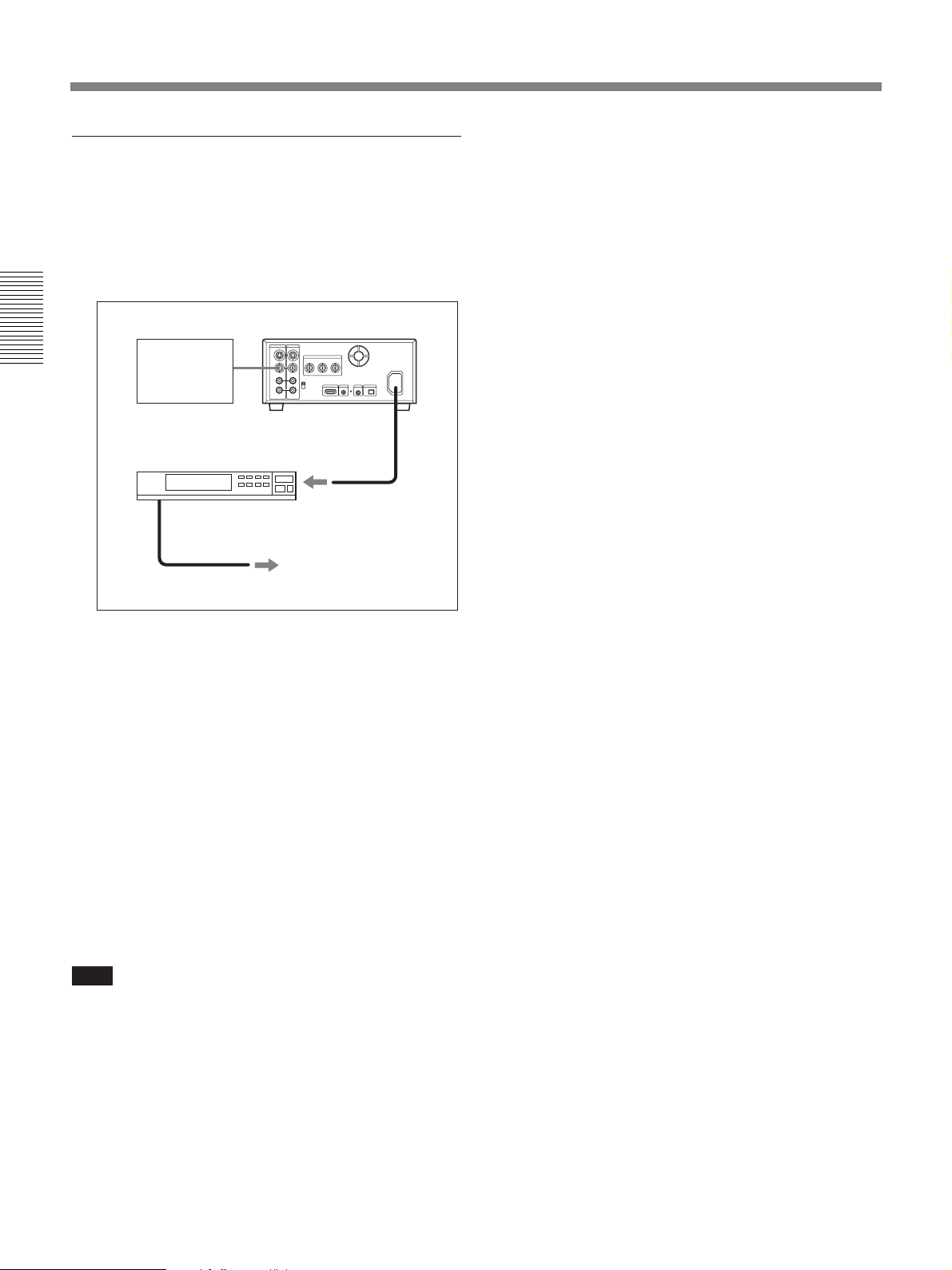
Using the Unit as a Videocassette Recorder
AC timer recording
By connecting the unit to an external AC timer (not
supplied), you can start recording at a preset time.
1 Connect the unit to an external AC timer (not
supplied).
HVR-M25 (rear panel)
Recording
Chapter 2 Playback and Recording
source
(external tuner,
etc.)
VIDEO INPUT
AC timer
to an AC outlet
If the tape ends before the recording source
stops operation
The tape stops.
To stop recording during timer recording
Press STOP button on the unit.
To release the AC timer recording mode
Set TIMER switch on the front panel of the unit to
OFF.
2 Insert a tape for recording.
3 Set INPUT SELECT switch of the unit to select
the input signals.
4 Set TIMER switch on the front panel of the unit to
REC.
5 Set the timer-on time on the connected AC timer.
At the preset time, the power of the unit turns on
automatically and recording starts after a few to
several ten seconds. Set the timer allowing a
margin for the recording to start. You do not need
to press REC button.
Note
To turn the unit off, press STOP button on the unit to
stop the tape transport operation beforehand.
If you turn the unit off while a tape is running, for
example, by using an AC timer, the unit or the tape
may be damaged.
48 Chapter 2 Playback and Recording
Page 49
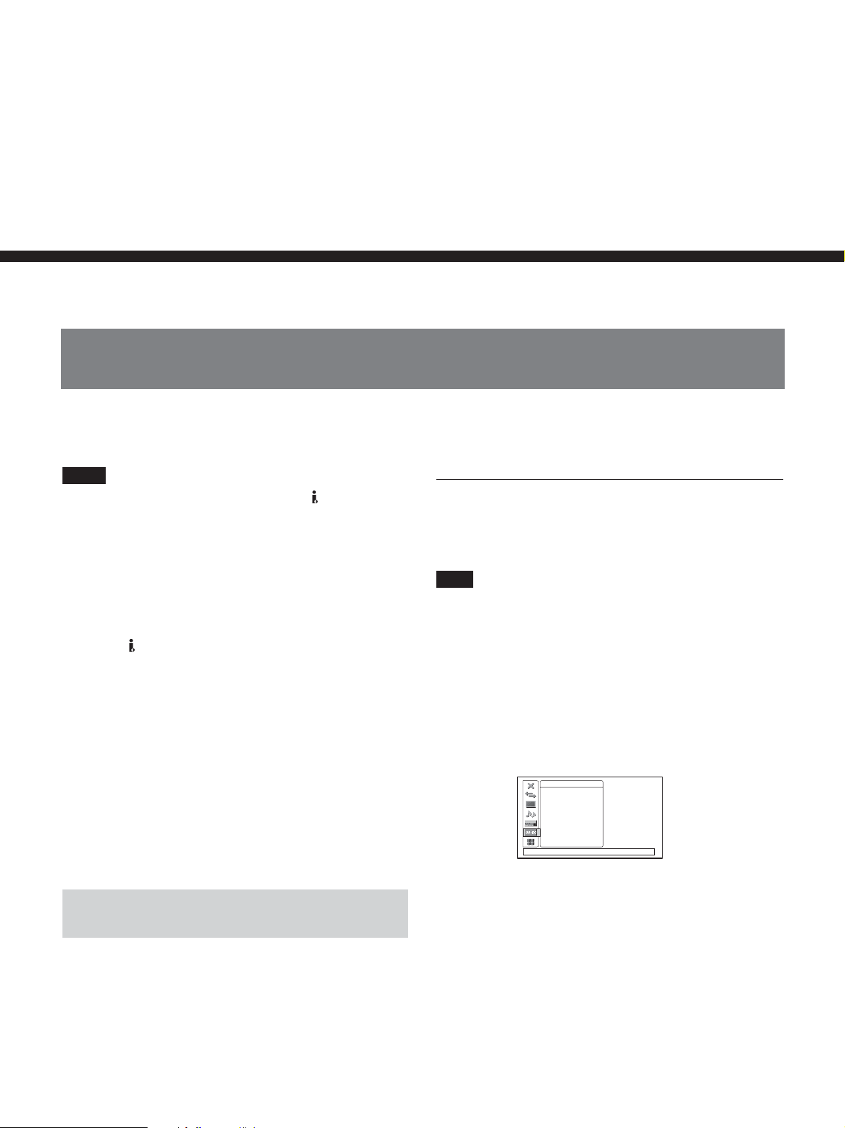
Setting the Time Code
Setting the Time Code and User Bits
Chapter3
The unit can set, display, record and play back the time
code and user bits.
Notes
•When HDV signals are recorded from HDV/DV
jack on the unit, user bits are copied automatically.
However, these bits cannot be preset. The time code
is set in accordance with [TC MAKE] setting. To
copy the time code of a source tape, set [HDV/DV IN
TC] in [TC/UB SET] menu to [EXTERNAL]
(page 76).
•When images recorded in DVCAM/DV format are
input via
HDV/DV jack, you can preset a user bit
time code on the unit. To copy the user bit and time
code of a source tape, use [DUPLICATE PLUS]
(page 74).
• For a tape recorded both in HDV and DVCAM/DV
formats, the time code may become garbled at a
connecting portion between scenes on the tape.
• If you play back an HDV tape without signals
recorded, the time cord may become disordered.
• The time code and user bits cannot be reset on the
unit from with Remote Commander equipped with a
counter reset function.
For details on the menu, see “Chapter 5 Adjusting and
Setting Through Menus” on page 65.
To set the initial time code value
This section describes how to set the time code’s initial
value.
Note
To set the initial time code value, you need to set [TC
MAKE] in [TC/UB SET] menu to [PRESET]
beforehand.
For details on [TC MAKE], see “TC/UB SET” menu on
page 76.
1 Press MENU button to display the menu.
For details on the menu, see “Operating the Menus” on
page 65.
TC/UB SET
TC PRESET
UB PRESET
HDV/DV IN TC
TC RUN
TC MAKE
TC FORMAT
[
MENU] : END
Chapter 3 Dubbing/Editing
Using the Internal Time Code Generator
You can set the initial time code value generated by
the internal time code generator. In addition, you can
set the user bits to record data such as the date, time,
scene number, reel number, or other useful
information. The time data settings are set by using the
menu.
(You can set [TC FORMAT] only when [60i/50i
SEL] in [OTHERS] menu is set to [60i].)
(Continued)
Chapter 3 Setting the Time Code 49
Page 50
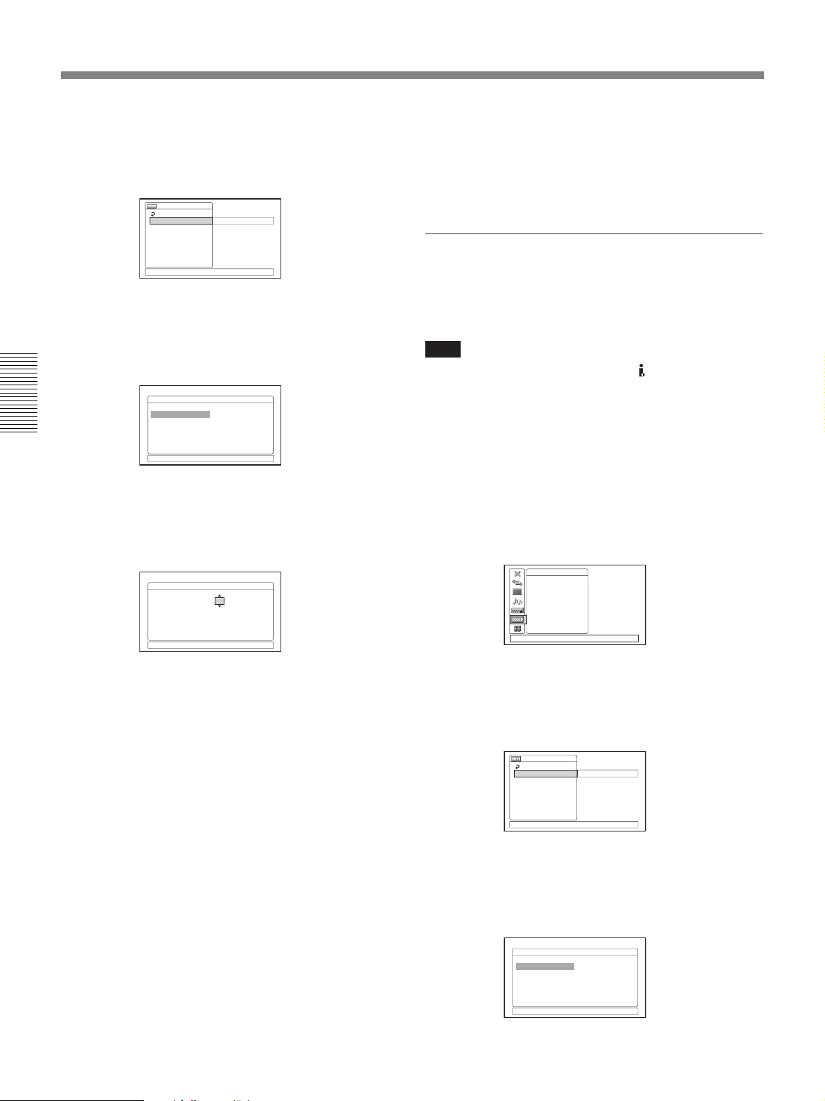
Setting the Time Code and User Bits
2 Press J/j buttons to select [TC/UB SET], then
press EXEC button.
The following menus are displayed.
TC/ UB SET
RETURN
TC PRESET
UB PRESET
HDV/DV IN TC
TC RUN
TC MAKE
TC FORMAT
[
MENU] : END
00:00:00:00
3 Press J/j buttons to select [TC PRESET], then
press EXEC button.
The following menus are displayed.
TC PRESET
OK
PRESET 00:00:00:00
RESET
Chapter 3 Dubbing/Editing
[
MENU] : END
4 Press J/j buttons to select [PRESET], then press
EXEC button.
The following menus are displayed.
TC PRESET
OK
PRESET
RESET
[
MENU] : END
00:00:00:00
To cancel the time code setting
Select [CANCEL] in step 7, then press EXEC button.
To reset the time code
Select [RESET] in step 4, then press EXEC button.
To set the value of the user bits
You can set the user bits as eight-digit hexadecimal
values (base 16) to have the date, time, scene number,
and other information inserted into the time code track.
Note
When HDV signals are input from HDV/DV jack,
the user bits of HDV signals are applied.
In the event of this, you do not have to follow the
procedures below.
When recording the internal color bars in HDV format,
user bits can still be set.
1 Press MENU button to display the menu.
For details on the menu, see “Operating the Menus” on
page 65.
TC/UB SET
TC PRESET
UB PRESET
HDV/DV IN TC
TC RUN
TC MAKE
TC FORMAT
[
MENU] : END
5 Set the first two digits. Press J/j buttons to select
the number, then press EXEC button.
6 Repeat step 5 to set the other eight digits.
7 Press J/j buttons to select [OK], then press
EXEC button.
The time code value is set. The menu display
returns to that of step 2.
8 Press J/j buttons to select [OK], then press
EXEC button.
The menu display returns to that of step 1.
50 Chapter 3 Setting the Time Code
2 Press J/j buttons to select [TC/UB SET], then
press EXEC button.
The following menus are displayed.
TC/ UB SET
RETURN
TC PRESET
UB PRESET
HDV/DV IN TC
TC RUN
TC MAKE
TC FORMAT
[
MENU] : END
00:00:00:00
3 Press J/j buttons to select [UB PRESET], then
press EXEC button.
The following menus are displayed.
UB PRESET
OK
PRESET 00 00 00 00
RESET
[
MENU] : END
Page 51

4 Press J/j buttons to select [PRESET], then press
EXEC button.
The following menus are displayed.
UB PRESET
OK
PRESET
RESET
[
MENU] : END
00 00 00 00
5 Set the first two digits. Press J/j buttons to select
the number, then press EXEC button.
6 Repeat step 5 to set the rest of the digits.
7 Press J/j buttons to select [OK], then press
EXEC button.
The user bit value is set. The menu display returns
to that of step 2.
8 Press J/j buttons to select [OK], then press
EXEC button.
The menu display returns to that of step 1.
To cancel the user bits setting
Select [CANCEL] in step 7, then press EXEC button.
To reset the user bits
Select [RESET] in step 4, then press EXEC button.
Note
The user bit is recorded at three-frame intervals for a
tape recorded in HDV1080i format.
•When HDV signals are input from
HDV/DV jack
the user bit value is also recorded, regardless of
[HDV/DV IN TC] setting.
•When this item is set to [EXTERNAL], INPUT
SELECT switch on the front panel is set to HDV/DV,
and no signal is input via
HDV/DV jack, or the
software of the editing controller does not output a
time code. If you start recording, bars (– –:– –:– –:– –)
are recorded as the time code. When time code
signals are input, the bars disappear to record the time
code signals.
•When this item is set to [EXTERNAL], if you input
time code to
HDV/DV jack that is not continuous or
does not advance correctly, the value of the recorded
or displayed time code may not be equal to the actual
value of the input one. If you use a tape with this
problem, you may not perform search or edit,
depending on the devices you use.
To set the time code when the recording
starts
Set [TC MAKE] in [TC/UB SET] menu to select the
time code to be recorded when recording starts.
REGENERATE: The time code value is set to
continue the time code from the time code already
recorded on the tape. If you start recording from a
blank portion of the tape, the time code starts from
“00:00:00:00”.
PRESET: The time code starts from the value set in
[TC PRESET] in [TC/UB SET] menu.
To set the advancement mode
Chapter 3 Dubbing/Editing
To select the time code when you record a
signal input to HDV/DV format
Set [HDV/DV IN TC] in [TC/UB SET] menu to select
whether to record the internal time code or an external
one.
INTERNAL: Records the time code internally
generated.
EXTERNAL: Records the time code with video and
audio signals input via
Notes
•When this item is set to [EXTERNAL], the time code
input via
HDV/DV jack and the user bits set in [UB
PRESET] are recorded.
HDV/DV jack.
Set [TC RUN] in [TC/UB SET] menu to switch the
advancement mode (counting up).
REC RUN: Time code advances only while
recording.
FREE RUN: Time code advances even when the
unit is not recording and the time indicator is
paused. Use this setting to adjust the default time
code to the current time and so on.
(Continued)
Chapter 3 Setting the Time Code 51
Page 52

Setting the Time Code and User Bits
Notes
• If you set the advancement mode to [FREE RUN],
the time code will be updated by the internal clock
while the unit’s power is off. The time code may have
been delayed or advanced when if you turn on the
unit power again, play back a tape, or set INPUT
SELECT switch to HDV/DV.
• If the internal backup battery charge is exhausted, the
time code of FREE RUN setting will be initialized.
The internal backup battery is fully charged if you
connect the power to the unit for about 24 hours. A
fully charged internal battery can run for about 3
months.
To set the frame mode (For 60i only)
Set [TC FORMAT] in [TC/UB SET] menu to switch
Chapter 3 Dubbing/Editing
the frame mode.
AUTO: Automatically sets the mode in accordance
with the loaded tape.
If nothing is recorded on the tape, the mode is set to
the non-drop frame mode. If the unit cannot read
the frame mode correctly from the tape, the unit
will use the mode that was set in the last position it
was able to read correctly on the tape. If you
remove the cassette, the mode of the last position it
was able to read correctly is cleared and the mode
is set to the non-drop frame mode. If [TC MAKE]
is set to [PRESET], the mode is also set to the nondrop frame mode.
DF: Selects the drop frame mode.
NDF: Selects the non-drop frame mode.
Note
When you set [60i/50i SEL] in [OTHERS] menu to
[50i], the unit applies the 50i system specification.
Therefore, the time code generated by the unit during
recording is that of the non-drop frame mode. Even if
60i system signals is input to
HDV/DV jack, when
[60i/50i SEL] in [OTHERS] menu is set to [50i], the
time code generated by the unit is the non-drop frame
mode regardless of [TC FORMAT] setting. To set the
unit to generate the time code in the drop frame mode,
set [60i/50i SEL] to [60i].
52 Chapter 3 Setting the Time Code
Page 53
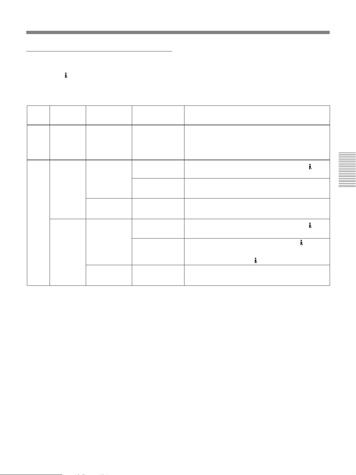
HVR-M25U/M25N/M25E/M25P time codes
The unit has a HDV/DV jack. The time code
displayed and recorded on the tape differs as shown
below when INPUT SELECT switch is set to HDV/
DV and when it is set to other than HDV/DV.
Playback
EE
[HDV/DV IN
TC] menu
INTERNAL
EXTERNAL
INPUT SELECT
switch
HDV/DV
S VIDEO
VIDEO
HDV/DV
S VIDEO
VIDEO
Mode
Playback
Audio dubbing
Playback at various
a)
speeds
b)
DUB1
Duplicate
DUPLICATE
b)
PLUS1
Recording
Recording Pause
b)
REC1
Recording
Recording Pause
b)
REC1
Duplicate
DUPLICATE
b)
PLUS1
Recording
Recording Pause
b)
REC1
Recording
Recording Pause
b)
REC1
Time code/User bits displayed and recorded
Time code/user bits on the tape
Time code/user bits of another device connected to HDV/
DV jack
Time code/user bits internally generated
c)
c)
When the input signal is HDV: User bits input via HDV/DV
Time code/user bits internally generated
Time code/user bits of another device connected to HDV/
DV jack
c)
c)
Time code input of another device connected to HDV/DV
jack and user bits internally generated
When the input signal is HDV: Time code/user bits of
another device connected to
Time code/user bits internally generated
HDV/DV jack.
c)
Chapter 3 Dubbing/Editing
a) This includes stop, fast-forward or rewind. If the unit
cannot read the time code on the tape correctly, the
counter displays “– –:– –:– –:– –”.
b) “DUB1”, “DUPLICATE PLUS1” and “REC1” represent
the state of the unit when you press each of these buttons
(AUDIO DUB, DUP or REC) in the stop mode.
c) The time code is also displayed on the time counter
screen. For details on the time counter, see page 26.
Chapter 3 Setting the Time Code 53
Page 54
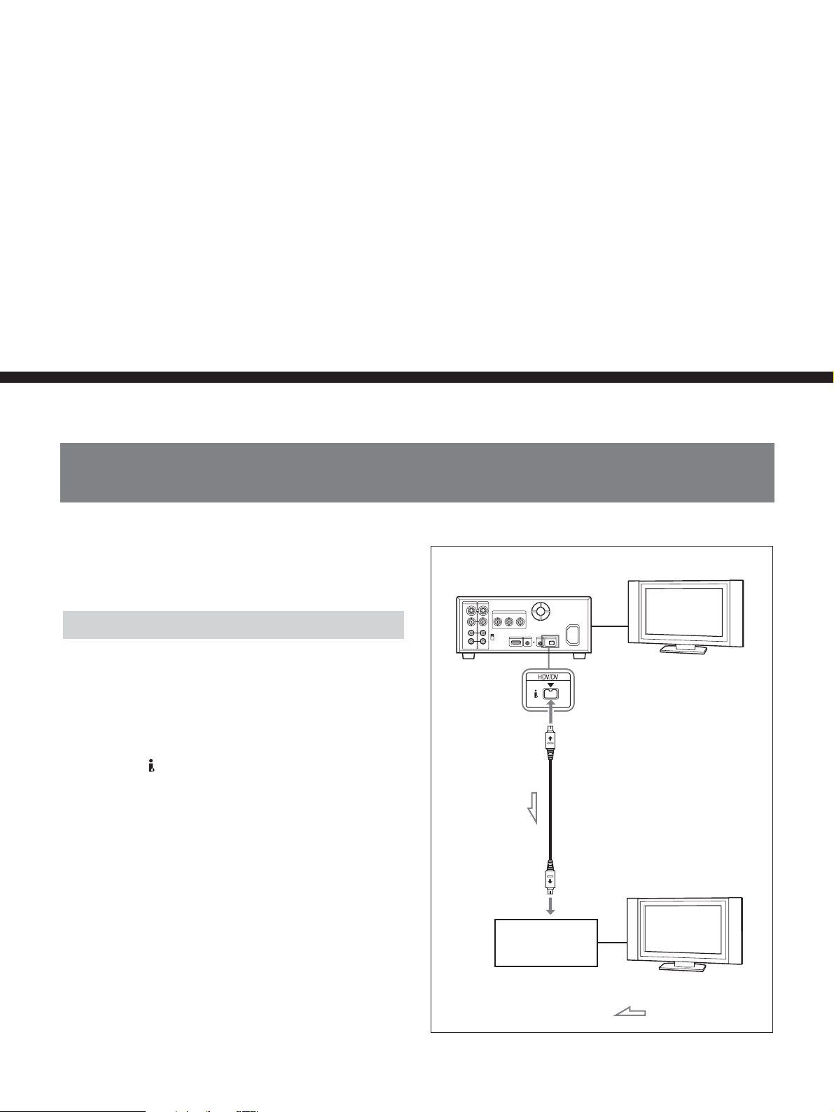
Chapter4
Dubbing to another equipment
using
i.LINK
jack, Duplication,
Audio Dubbing, and Connecting
with a Computer
Dubbing to another equipment using i.LINK jack
Chapter 4 Dubbing to another equipment using i.LINK jack, Duplication, Audio Dubbing, and Connecting with a Computer
This section describes the connections and settings
necessary to perform dubbing on other equipment,
using the unit as a video player.
Connections for Dubbing
Connect the unit to the recorder as shown right using
an i.LINK cable.
The signal flow is automatically detected so you do not
need to make separate connections for input and
output. Also, connecting the unit to an editing
controller via
digital non-linear editing system.
For connections of the editing controller and the unit, refer
to the editing controller instruction manual.
HDV/DV jack, you can configure a
HVR-M25 (rear panel)
Monitor
i.LINK cable (not supplied)
Before dubbing, you must set the format in which you
want to output signals. Perform [HDV/DV SEL] (page
67) and [i.LINK SET] (page 69) settings in [IN/OUT
REC] menu.
For details, refer to “Compatibility of HDV, DVCAM, and
DV Formats” (page 93).
To dub a tape recorded in HDV format using duplicate
function on such as DSR-25/45/50, select [DVCAM]
in [HDV t DV CONV] of [i.LINK SET] in [IN/OUT
REC] menu.
54 Chapter 4 Dubbing to another equipment using i.LINK jack, Duplication, Audio Dubbing, and Connecting with a Computer
i.LINK jack
Digital video
equipment with an
i.LINK jack
Monitor
: Signal flow
Page 55

There are some limitations to down convert a tape
recorded in HDV format to DVCAM format.
For details, see “i.LINK SET” on page 69.
Dubbing procedures
Notes
• If you output pictures in the playback pause mode
when connected with an i.LINK cable, recorded
images may appear distorted.
•When the tape is recorded in HDV format, the picture
is output as a simplified picture during playback in
various speeds (page 37).
•When connected with an i.LINK cable, you cannot
output only pictures or sounds separately.
• When you duplicate down converted signals from
HDV to DVCAM on an HDV/DV cassette in
DVCAM format, the available recording time is
reduced to about 2/3 of the recording time indicated
on the tape. However, when a DVCAM cassette is
recorded using DVCAM format, the available
recording time is the same as the recording time
indicated on the DVCAM cassette.
1 Prepare the unit.
Refer to “Settings for Recording” on page 45.
2 Prepare the recorder.
If the recorder has an input selector switch, select
an input.
For details, refer to your recorder’s instruction manual.
3 Start playback on the unit and start recording on
the recorder.
For details, refer to your recorder’s instruction manual.
4 When dubbing is finished, stop recording on the
recorder, and then stop playback of the unit.
Chapter 4 Dubbing to another equipment using i.LINK jack, Duplication, Audio Dubbing, and Connecting with a Computer
Chapter 4 Dubbing to another equipment using i.LINK jack, Duplication, Audio Dubbing, and Connecting with a Computer 55
Page 56
Duplication (generating a work tape with the same time code)
DUPLICATE PLUS is a dubbing function which
duplicates the tape with time codes through i.LINK
connection. By using DUPLICATE PLUS, it helps to
make a work tape which contains the exact same time
code that the original source tape contains.
DUPLICATE PLUS is applicable with HDV1080i,
DVCAM, and DV (SP) formats. Also, at the tape end
or the tape in PAUSE by operating STOP button, you
can change the tape of both the player and recorder
during duplication (page 58). Therefore, multiple tapes
can be duplicated from multiple resource tapes on a
tape continuously.
(The unit does not support cassette memory
Note
Use this function when making a one-to-one
connection. Also, do not disconnect the i.LINK cable
during duplication.
.)
Setting DUPLICATE PLUS mode
Set [DUPLICATE PLUS] mode in [VTR SET] menu.
•When the format of a tape is switched to a different
format during duplication, the portion where the
format is switched may be distorted.
Setting the auto rewind function
Set [AUTO REW] in [DUPLICATE PLUS] to select
whether you want to use the auto rewind function.
ON : Rewinds the tape on both the player and the
recorder, and starts duplication. Also, when you
continue to duplicate a resource tape from multiple
tapes, the new work tape will be rewound
automatically and start duplication.
OFF : Starts duplicating from the current portion of
the tape.
Note
Depending on the specification of the player, you may
not search on the beginning of a tape. In this case, set
[AUTO REW] to [OFF].
Operating DUPLICATE PLUS
Setting the duplicating format
Chapter 4 Dubbing to another equipment using i.LINK jack, Duplication, Audio Dubbing, and Connecting with a Computer
Select the duplicating format with [FORMAT SEL] in
[DUPLICATE PLUS] mode. The unit functions the
same as it has detected a blank portion on a tape, if the
unit detects a format other than the selected format
(page 58).
ALL : Duplicates the original tape on the recorder.
HDV1080i : The player automatically detects
HDV1080i format and duplicate.
DVCAM : The player automatically detects
DVCAM format and duplicate.
DV SP : The player automatically detects DV (SP)
format and duplicate.
Notes
• If the original signal is mixed with other type of
signal as you transfer the image to a computer, the
transfer procedures may be interrupted. When
transferring an image using a tape dubbed with
DUPLICATE PLUS on the unit to a computer, we
recommend you to duplicate it in a single format.
•When a non-compatible HDV signals (HDV720p,
etc.) is input during duplication after [FORMAT
SEL] is set to [ALL], the HDV signals are recorded
as an unrecorded portion. Also, when the
incompatible DV signals (DV LP etc.,) are input, the
signal is recorded in DV SP.
The duplicating procedures of DUPLICATE PLUS
differs depending on the duplicate settings.
Note
If you operate the player while duplicating, the
duplicate process may be interrupted and the tape may
not be correctly duplicated. Do not operate the player
while duplicating.
When [AUTO REW] in [DUPLICATE PLUS] is
set to [ON]:
1 Connect the unit and the player using an i.LINK
cable (not supplied). After turning on the power of
the unit, set INPUT SELECT switch on the unit to
HDV/DV.
2 Press STOP button on the unit to stop the tape.
3 While holding DUPLICATE PLUS button down,
press PLAY button on the unit.
The unit and the player will automatically rewind
the tape to the beginning. The unit enters the
duplicate-standby mode. The player enters the
playback pause mode. Then DUPLICATE PLUS
and PLAY indicators on the unit light and the
duplication starts.
56 Chapter 4 Dubbing to another equipment using i.LINK jack, Duplication, Audio Dubbing, and Connecting with a Computer
Page 57

Notes
•Before you start duplication, make sure that the
player has finished loading the cassette.
• The duplication starts after the i.LINK connection is
established so that the first part of the source tape is
dropped on the copied tape.
• If the player has functions such as auto repeat, set
them to OFF.
• If the player has a still timer function, set the still
timer to the longest time to ensure enough time for
rewinding the tape to the beginning.
•When you use a DSR-45 as the player, set REMOTE/
LOCAL switch of the DSR-45 to [LOCAL].
• If you operate the player while duplicating and the
PLAYER UNCONTROLLABLE warning message
appears and duplication stop, press EXEC button on
the unit to end duplication once and repeat the
procedures.
When [AUTO REW] in [DUPLICATE PLUS] is
set to [OFF]:
1 Connect the unit and the player using an i.LINK
cable (not supplied). After turning on power of the
unit and the player, set INPUT SELECT switch on
the unit to HDV/DV.
2 Locate the points where you want to start playback
and recording on each tape.
Notes
•Before you start duplication, make sure that the
player has finished loading the cassette.
• The duplication starts after the i.LINK connection is
established so that the first part of the source tape is
dropped on the copied tape. Play back the tape a few
frames back of the portion where you want to begin
the duplication.
• If the player has functions such as auto repeat, set
them to OFF. Also, when the player has an auto
rewind function, set the function to ON.
•You may not duplicate the beginning of the source
tape. Locate the recorded portion on the source tape,
and then start duplication.
• If there is a blank portion on the tape, the first part of
the recorded portion that follows may be dropped on
the copied tape.
•When the time code on a player operates either
discontinuously or incorrectly, the difference in frame
values between the numeric time codes may occur.
To cancel duplication
1 Press STOP button on the unit, and pause
duplicating.
While pausing, the following confirmation display
appears.
Chapter 4 Dubbing to another equipment using i.LINK jack, Duplication, Audio Dubbing, and Connecting with a Computer
3 Press STOP button on the unit.
4 While holding DUPLICATE PLUS button down,
press PLAY button on the unit.
The unit enters the duplicate-standby mode. The
player enters the playback pause mode. Then
DUPLICATE PLUS and PLAY indicators on the
unit light and duplication starts.
To adjust the point where duplication starts, while
holding DUPLICATE PLUS button down, press
PAUSE button and PLAY button in step 4. The unit
will not start duplication until you press PAUSE
button again.
After confirming that the PLAYER display has
changed to [READY] (blinking) on LCD monitor,
adjust the duplication start point using the player, then
press PAUSE button on the unit to start duplication.
DUPLICATE PLUS
[ X ] : RESTART
2 Press j button.
Duplicating mode ends.
Can adjust start
position or change
cassette.
[ x ] : END
00:12:34:12
Chapter 4 Dubbing to another equipment using i.LINK jack, Duplication, Audio Dubbing, and Connecting with a Computer 57
Page 58
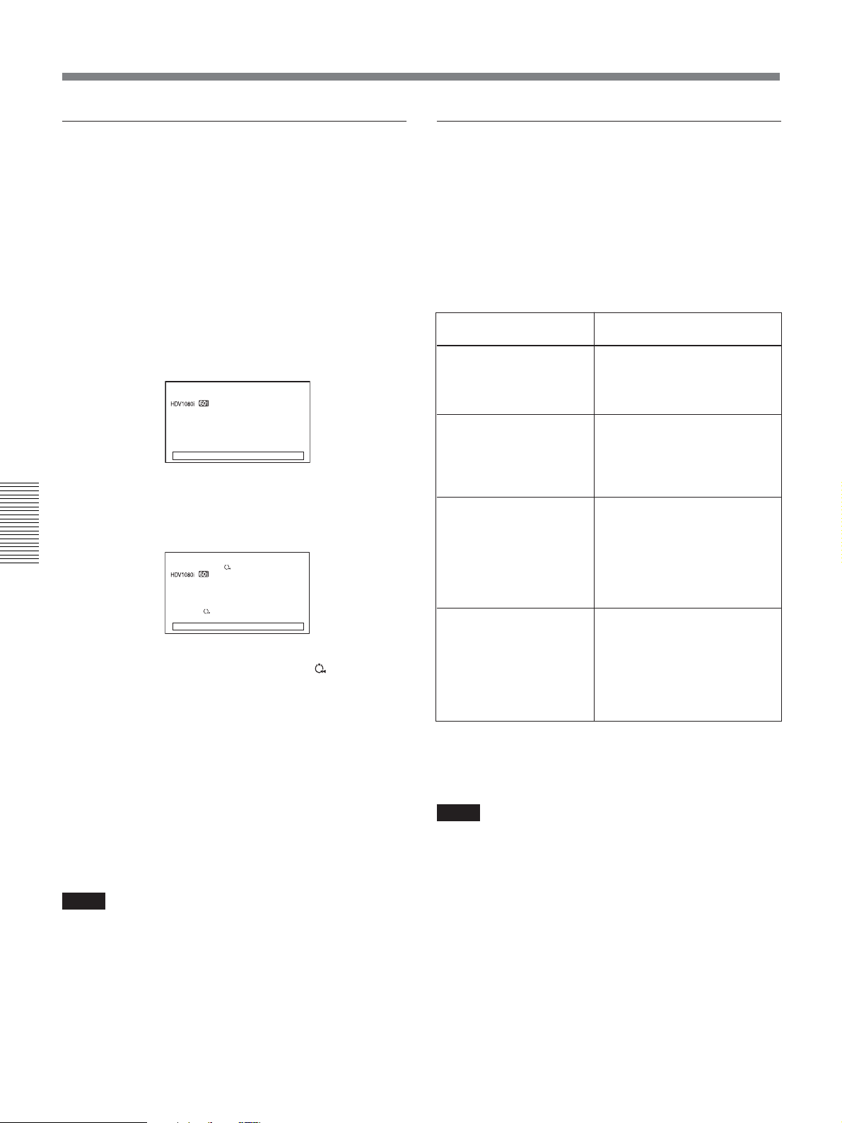
Duplication (generating a work tape with the same time code)
Duplicating a series of tapes
Detecting a blank portion during
duplication
While pausing duplication mode, you can change the
tape on the player. Therefore, you can duplicate a
series of tapes on a single tape.
To change the tapes
1 By playing back the tape on the player to the end
or by pressing STOP button on the unit, confirm
that the player enters the playback pause mode.
During pause, the confirmation display appears.
DUPLICATE PLUS
Can adjust start
position or change
cassette.
[ X ] : RESTART
00:12:34:12
[ x ] : END
2 Eject the tape in the player, and load the another
tape.
Chapter 4 Dubbing to another equipment using i.LINK jack, Duplication, Audio Dubbing, and Connecting with a Computer
DUPLICATE PLUS
Can adjust start
position or change
cassette.
PLAYER :
[ X ] : RESTART
When [AUTO REW] is set to [ON],
00:12:34:12
[ x ] : END
is
displayed.
You can eject the tape on the recorder to insert a
new tape at this time.
3 Press J button.
If the unit detects a blank portion on the source tape
during duplication, it skips the blank portion
automatically, reducing the length of the recorded part
of the tape.
The operations of the player and recorder (the unit)
when a blank portion is detected are as follows:
Detected status on
source tape
Detects a blank portion
Certain seconds after
detection of a blank
portion
Detects next recorded
portion
Returns to the location
immediately before the
blank portion ends
The unit performs the above operations automatically
to reduce the blank portion of a tape during
duplication.
Player/Recorder (the unit)
operation
Player: Continues playing the
tape.
Recorder: Continues
recording.
Player: Continues playing the
tape another certain
seconds and searches
forward.
Recorder: Stops.
Player: Rewinds the tape at
about –2 times its
normal speed to the
location immediately
before the blank
portion ends.
Recorder: Remains stopped.
Player: After entering the
playback pause mode,
starts playing the tape.
Recorder: After entering the
recording pause
mode, starts
recording.
Duplication starts again.
Notes
•Depending on the specifications, the skip function
When [AUTO REW] is set to [ON], the newly
inserted tape is rewound automatically.
may not work on some players.
•When the unit resumes duplication, the first part of
the recorded portion on the source tape may be
Notes
•When you change the source tapes, the beginning of
the connecting portion of the recorded content of the
dropped on the copied tape.
•A recorded portion of less than one minute between
two blank portions may not be duplicated.
work tape may be distorted.
•When you start duplication again, the beginning of
the recorded content of the work tape may be
distorted as playback starts again.
58 Chapter 4 Dubbing to another equipment using i.LINK jack, Duplication, Audio Dubbing, and Connecting with a Computer
Page 59
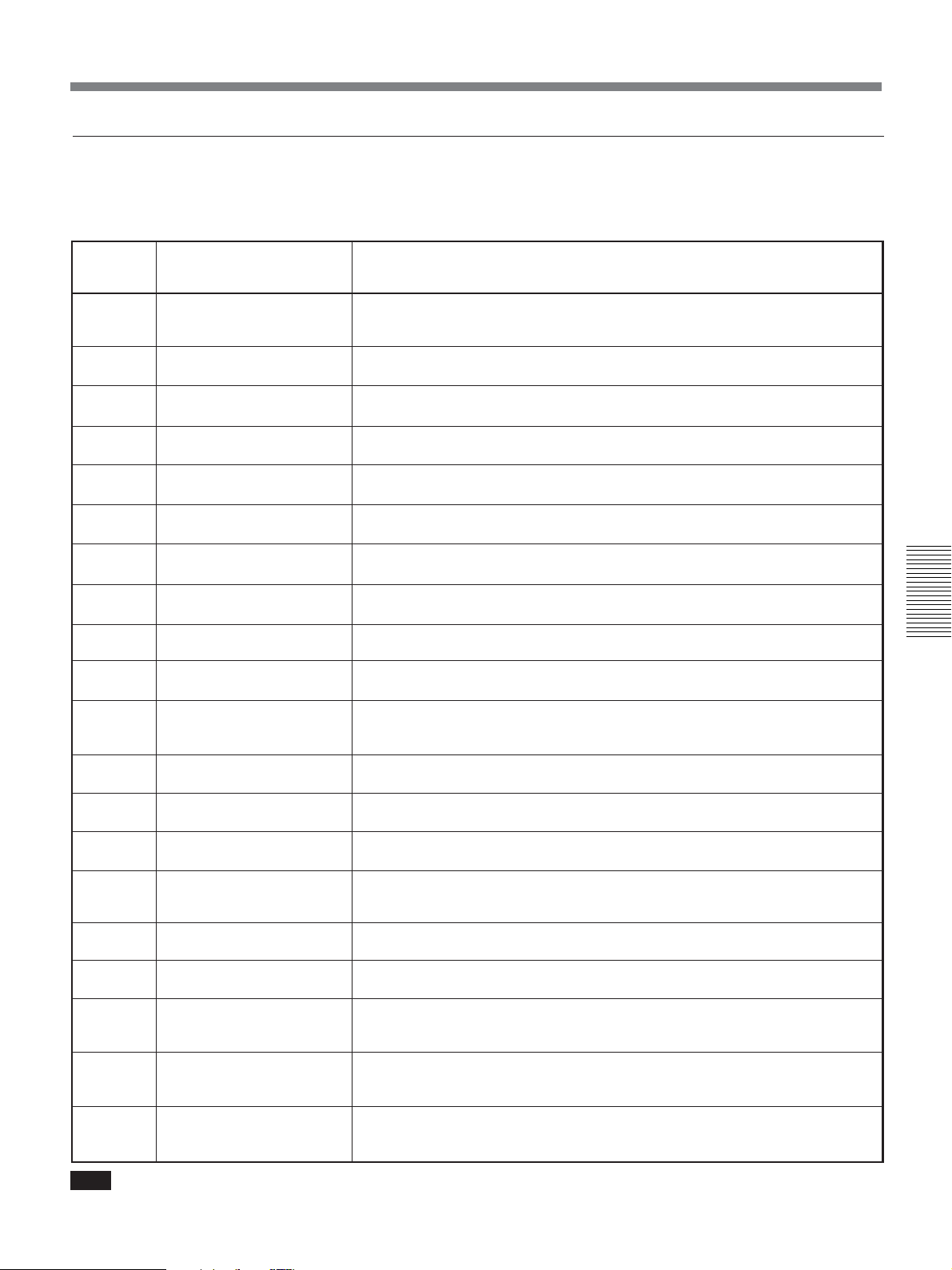
Warning messages on duplication
If an error occurs during duplication, a STOP/
CAUTION number and warning message will be
displayed on LCD monitor and the video output screen.
The following table lists these warnings and messages.
If a warning message is displayed, check this table and
take the appropriate action.
STOP/
CAUTION
No.
00
01
02
03
10
11
12
13
14
15
16
17
18
20
21
22
23
24
25
26
Warning Message
RECORDER:
INPUT SELECT is not set to
HDV/DV.
i.LINK :
Cable not connected.
i.LINK :
Check i.LINK connection.
i.LINK :
Check i.LINK connection.
PLAYER:
Recording.
PLAYER:
No cassette
PLAYER:
Cannot control.
PLAYER:
Cannot control.
PLAYER:
Cannot control.
PLAYER:
Cannot control.
PLAYER:
Cannot record due to
copyright protection.
PLAYER:
Error detected.
PLAYER:
Moisture
RECORDER:
No cassette inserted.
RECORDER:
The tape is locked.
–check the tab.
RECORDER:
Reinsert the cassette.
RECORDER:
Re-attach the power source
RECORDER:
Condensation. Cannot open.
Try later.
RECORDER:
Moisture condensation.
Turn off for 1H.
RECORDER:
Dirty video head.
Use a cleaning cassette.
Cause/Remedy
INPUT SELECT switch on the recorder (the unit) is not set to HDV/DV.
t Set INPUT SELECT switch to HDV/DV.
The i.LINK cable is not connected correctly.
t Connect the i.LINK cable correctly.
There are multiple i.LINK connections or the i.LINK connection is looped.
t You cannot connect multiple devices. Connect only one player to the unit.
The i.LINK cable has been unplugged and plugged in again.
t Check the i.LINK cable connection. Try to duplicate again.
The player is in the recording mode.
There is no cassette in the player.
The player cannot be controlled.
The player rejects control.
The player is disabled or is in a different mode than the recorder (the unit) has
requested.
The player is under an inappropriate condition.
A copyright protected signal is recorded on the cassette in the player.
t You cannot duplicate copyright protected signals.
The player has detected self-diagnostics.
Moisture condensation has occurred in the player.
t Refer to the instruction manual of the player.
There is no cassette in the recorder.
REC/SAVE switch is set to SAVE switch on the cassette.
t Slide REC/SAVE switch to REC on the cassette.
The recorder (the unit) detected self-diagnostics.
t Insert a cassette again.
The recorder (the unit) detected self-diagnostics.
t Remove the power cord from the recorder.
Moisture condensation has occurred while the cassette is in the recorder (the
unit).
t Remove the cassette and power on and wait for more than one hour.
Moisture condensation has occurred while the cassette is not in the recorder.
t Power on the recorder and wait for more than one hour.
The recorder’s (the unit) video heads are clogged.
t Clean the video heads with the supplied cleaning cassette
(see page 90)
Chapter 4 Dubbing to another equipment using i.LINK jack, Duplication, Audio Dubbing, and Connecting with a Computer
.
Note
When a warning message other than above is displayed, consult your Sony dealer.
Chapter 4 Dubbing to another equipment using i.LINK jack, Duplication, Audio Dubbing, and Connecting with a Computer 59
Page 60
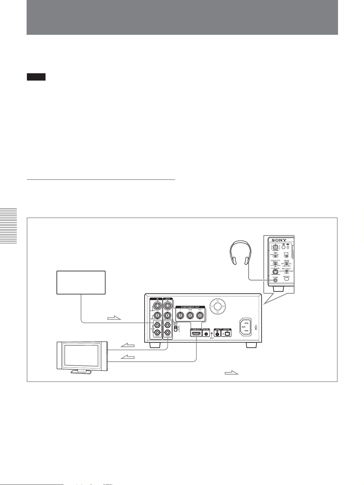
Audio Dubbing
You can record just sound on a recorded tape.
(Audio dubbing)
Notes
•You can dub the sound onto a DVCAM-formatted
tape recorded in the 32 kHz audio mode (4-channel/
12 bits) only. You cannot dub the sound on a tape in
the 48 kHz audio mode (2-channel/16 bits). If the
audio mode of the recorded tape is 32 kHz, you can
dub the sound regardless of [AUDIO MODE] setting
in [AUDIO SET] menu.
For details on “AUDIO MODE,” see “AUDIO SET”
menu on page 73.
• The sound is dubbed only onto channels 3/4.
You cannot dub the sound onto channels 1/2.
Connection of external devices
The following shows an example of a basic connection
for audio dubbing.
Chapter 4 Dubbing to another equipment using i.LINK jack, Duplication, Audio Dubbing, and Connecting with a Computer
Sound source
Monitor
Audio output
AUDIO INPUT
Audio
input
Video
input
HVR-M25 (rear panel)
AUDIO OUTPUT
VIDEO OUTPUT
When an HDMI cable is used for connection, Audio
cable connection is not necessary.
HVR-M25
(front panel)
Headphones
PHONES
: Signal flow
60 Chapter 4 Dubbing to another equipment using i.LINK jack, Duplication, Audio Dubbing, and Connecting with a Computer
Page 61

Dubbing sound
1 Connect AUDIO INPUT jack of the unit and the
sound source using a phono jack cable (not
supplied).
To pause audio dubbing
Press PAUSE button.
Pressing PAUSE button again resumes audio dubbing.
To stop audio dubbing
Press STOP button.
2 Set INPUT SELECT switch to a setting other than
HDV/DV.
3 Switch AUDIO INPUT LEVEL switch to select
the audio input signal level (–10, –2 or +4).
4 Play back the tape inserted in the unit.
5 At the point you want to start dubbing, press
PAUSE button to turn the unit to the playback
pause mode.
6 While holding AUDIO DUB button down, press
PLAY button to turn the unit to the audio dubbing
pause mode.
AUDIO DUB indicator on the unit lights.
7 Set AUDIO INPUT switch to set the adjusting
method of the recording level.
8 Adjust the recording level by turning AUDIO REC
LEVEL control knobs.
To monitor the sound you want
Set AUDIO OUTPUT SELECT switch as follows:
CH-1/2: You can listen to sound recorded on
channels 1/2 on the tape.
CH-3/4: You can listen to sound to be dubbed on
channels 3/4.
MIX: You can listen to the sound on the tape and the
dubbed sound.
For details on the audio levels display in the audio dubbing
mode, see page 27.
Notes
•You can monitor the sound on the tape while dubbing
the sound. However, there are some delays between
the sound being recorded and the sound being played.
When you play back the tape after audio dubbing,
you might hear the dubbed sound later than the sound
monitored during audio dubbing.
•You cannot dub sounds onto a blank portion of the
tape.
Chapter 4 Dubbing to another equipment using i.LINK jack, Duplication, Audio Dubbing, and Connecting with a Computer
You can adjust the recording level with AUDIO
REC LEVEL control knobs if you have selected
MANU in step 7. While looking at the audio level
meters on STATUS CHECK screen, turn AUDIO
REC LEVEL control knobs and adjust the
recording level. Adjust the audio recording level so
that the recording level does not exceed 0 dB when
the audio signal is at its maximum. If the recording
level exceeds 0 dB, the sound will be distorted.
9 Press PAUSE button.
PAUSE indicator goes off and audio dubbing
starts.
Chapter 4 Dubbing to another equipment using i.LINK jack, Duplication, Audio Dubbing, and Connecting with a Computer 61
Page 62
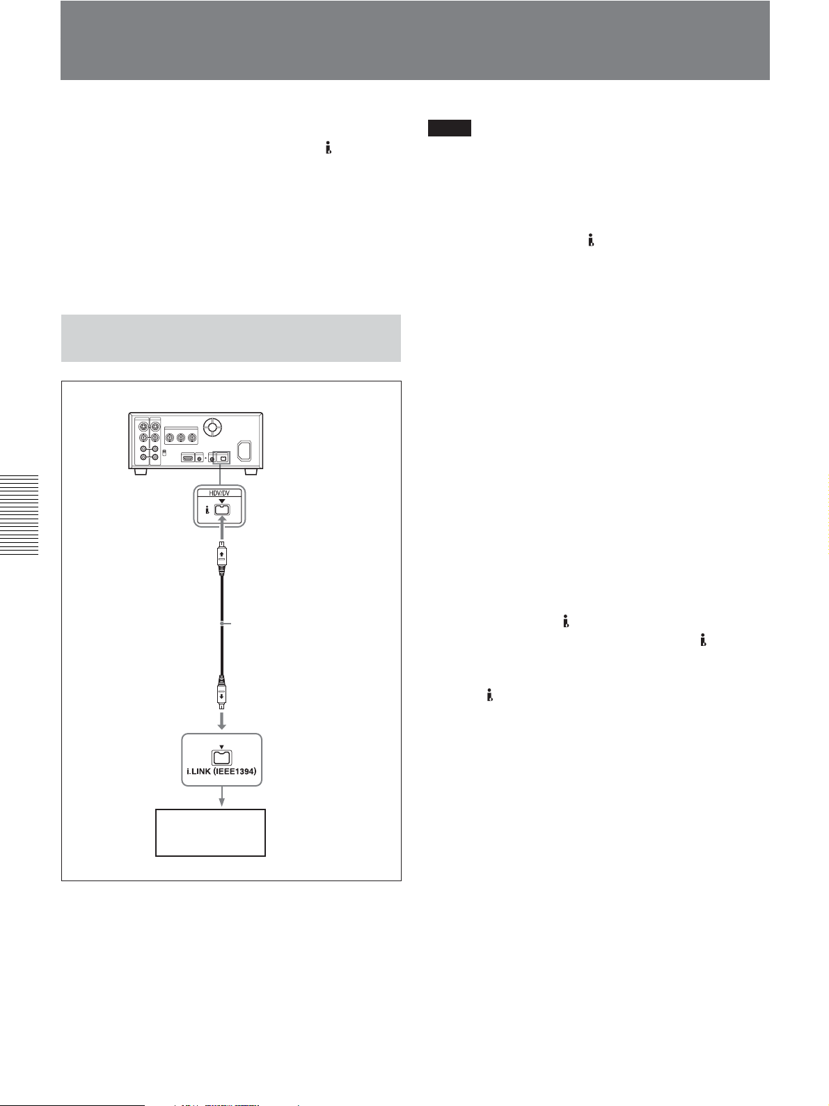
Editing (Connecting with a Computer)
You can set up an editing system by connecting the
unit to a computer (editing machine) using
HDV/DV
jack on the unit.
Notes
•Be sure to connect the i.LINK cable to a computer
(editing machine) first and then connect it to the unit.
If you connect the i.LINK cable to the unit first, it
• For details on the connecting method to the editing
machine, refer to the supplied instruction manual of
your editing unit.
• The editing functions you can use depend on the
editing software. For details on editing methods, refer
to the instruction manual of your editing software.
may cause the unit to malfunction because of static
electricity.
• If no picture appears via
the i.LINK cable, then reinsert it straight.
• If the unit is connected to a device equipped with an
i.LINK jack, when you intend to disconnect or
reconnect the i.LINK cable, turn off the device and
Connecting the Unit to a Computer
pull out the plug of its power cord from the wall
outlet beforehand. If you connect or disconnect the
i.LINK cable while the device is connected to the AC
outlet, high-voltage current (8 to 40 V) is output from
HVR-M25 (rear panel)
the i.LINK jack of the device to the unit, which may
cause a malfunction.
•Before connecting the i.LINK cable, set [HDV/DV
SEL] and [i.LINK SET] in [IN/OUT REC] menu. If
you perform the settings after connecting the cable,
the computer (editing machine) may not recognize
the unit correctly or may freeze.
• If you input or output signals in a format
incompatible with the computer (editing machine),
Chapter 4 Dubbing to another equipment using i.LINK jack, Duplication, Audio Dubbing, and Connecting with a Computer
the computer may not recognize the unit correctly or
may freeze.
•When set to EE mode, the unit outputs analog signals
i.LINK cable (not supplied)
those are input from
VIDEO or VIDEO signals are output from
DV jack, according to the setting of INPUT SELECT
switch. To output the playback image from the unit
through
HDV/DV jack only, set INPUT SELECT
switch to HDV/DV.
HDV/DV jack, disconnect
HDV/DV jack to a computer. S
HDV/
Computer
(editing machine)
62 Chapter 4 Dubbing to another equipment using i.LINK jack, Duplication, Audio Dubbing, and Connecting with a Computer
Page 63

Preparations
Transferring picture data from the unit to a
computer (editing machine)
• To transfer the picture data recorded on a tape to an
editing machine in HDV, set [HDV/DV SEL] in [IN/
OUT REC] menu to [HDV] (page 67), then set
[HDVtDV CONV] of [i.LINK SET] in [IN/OUT
REC] menu to [OFF] (page 69).
• To transfer the picture data recorded on a tape in
DVCAM (DV) to an editing machine, set
[HDVtDV CONV] of [i.LINK SET] in [IN/OUT
REC] menu to [OFF] (page 69).
• To transfer the picture data recorded on a tape in
HDV to an editing machine in DVCAM (DV), select
[DVCAM] or [DV SP] in [HDV t DV CONV] of
[i.LINK SET] in [IN/OUT REC] menu, then set
[DOWN CONVERT] (page 69).
Notes
• The operation may not work with some of your
editing machine software. Before using the software,
confirm that it is compatible with the unit.
• The unit cannot up convert a tape recorded in
DVCAM (DV) format to HDV format when
transferring the picture data on an editing machine.
• If you use a tape recorded both in HDV and DVCAM
(DV) formats when [HDV/DV SEL] is set to
[AUTO], the computer (editing machine) may not
recognize the unit or you may not edit the tape
correctly.
• There are restrictions on the video output when you
play back a tape recorded in HDV format at various
speeds. Refer to the table for “HDV-formatted tape”
in “Playing at various speeds” (page 37).
•When you use a tape that was down converted from
HDV to DVCAM or DV, some conventional
DVCAM/DV editing software may not perform the
time code search or this operation could result in an
error.
•When you record HDV signals that are input through
HDV/DV jack, a connecting portion between scenes
on the tape will be displayed as a still picture for
approximately 1 second. We recommend you to
perform digital nonlinear editing.
• If your editing software has the capability to output
the time code as well as the video and audio signals
to the unit, and you intend to record that time code,
set [HDV/DV IN TC] in [TC/UB SET] menu of the
unit to [EXTERNAL].
For details on TC/UB SET menu, see “TC/UB SET” menu
on page 75.
•When [HDV/DV IN TC] in [TC/UB SET] menu is
set to [EXTERNAL], if you input time code to the
HDV/DV jack that is not continuous or does not
advance correctly, the value of the recorder or
displayed time code may not be equal to the actual
value of the input one. If you use a tape recorded
under such condition, you may not perform search or
edit the picture, depending on the device you use.
• For connection of the editing controller and its
peripheral devices, refer to the instruction manual of
the editing controller and that of the editing software
you use.
• The editing functions you can use depend on the
editing software. For details on editing methods, refer
to the instruction manual of your editing software.
• The unit has a function to down convert HDV signals
to DVCAM (DV) signals to output from
HDV/DV
jack. Some software may not edit the DVCAM/DV
signals that are down converted from HDV signals
correctly. In this case, follow the procedures below
for tape duplication, then use the duplicated tape
when editing the picture.
Creating a DVCAM compatible tape
Set [HDV t DV CONV] of [i.LINK SET] in [IN/
OUT REC] menu to [DVCAM], then perform
DVCAM recording using a recording device that
accepts DVCAM format.
Creating a general consumer DV compatible
tape
Set [HDV t DV CONV] of [i.LINK SET] in [IN/
OUT REC] menu to [DV SP], set [DOWN
CONVERT] then perform DV recording using a
recording device that accepts DV format.
Chapter 4 Dubbing to another equipment using i.LINK jack, Duplication, Audio Dubbing, and Connecting with a Computer
Chapter 4 Dubbing to another equipment using i.LINK jack, Duplication, Audio Dubbing, and Connecting with a Computer 63
Page 64

Transferring picture data from a computer
(editing machine) to the unit
• To transfer the picture data recorded on a tape to an
editing machine in HDV, set [HDV/DV SEL] in [IN/
OUT REC] menu to [HDV], then set [HDV t DV
CONV] of [i.LINK SET] in [IN/OUT REC] menu to
[OFF] (page 69).
• To transfer the picture data to a computer (editing
machine) in DVCAM (DV) format, set [HDV/DV
SEL] to [DV] (page 67). Then, according to the
desired recording format, set [
[DVCAM] or [DV SP] (page 67). Also, according to
your edit software, select [DVCAM] or [DV SP] in
[HDV t DV CONV] of [i.LINK SET] in [IN/OUT
REC] menu (page 69).
REC MODE] to
Chapter 4 Dubbing to another equipment using i.LINK jack, Duplication, Audio Dubbing, and Connecting with a Computer
64 Chapter 4 Dubbing to another equipment using i.LINK jack, Duplication, Audio Dubbing, and Connecting with a Computer
Page 65

Adjusting and Setting
Through Menus
Operating the Menus
Chapter5
The unit allows you to set various parameters in the
menus. Before you start using the unit, set the internal
clock in [CLOCK SET] in [OTHERS] menu. Except
for clock setting, you can use all other factory-set
default parameters but change them as needed.
Notes
•Do not pull out the power cord plug while operating
the menus. Otherwise, the settings of the menu may
be changed accidentally.
• If the internal backup battery is exhausted, the time
set in the internal clock, 60i/50i setting, and the time
code of FREE RUN setting will be initialized. The
internal backup battery is fully charged if you
connect the power to the unit for about 24 hours. A
fully charged internal battery can run for about 3
months.
Displaying the menu
1 Press MENU button.
2 Pressing J/j buttons, select the menu icon you
want to change, then press EXEC button.
3 Pressing J/j buttons, select the submenu you
want to change, then press EXEC button.
4 Pressing J/j buttons, change the setting.
5 Press EXEC button to return to the submenu.
6 Repeat steps 1 to 5, as needed.
To return to the previous menu level, press J/j
buttons and select [
You can use K/k buttons to move the menu cursor
and to adjust increase/decrease settings.
RETURN].
Chapter 5 Adjusting and Setting Through Menus
Chapter 5 Adjusting and Setting Through Menus 65
Page 66
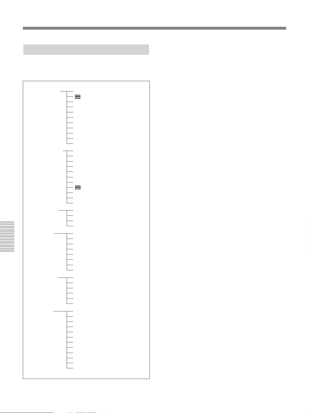
Operating the Menus
Menu Organization
The menu of the unit consists of the following menus
and submenus.
IN/OUT REC
DISPLAY SET
AUDIO SET
VTR SET DUPLICATE PLUS (
Chapter 5 Adjusting and Setting Through Menus
TC/UB SET TC PRESET (
OTHERS ASSIGN BTN (
HDV/DV SEL (
REC MODE (
VIDEO OUT (
i.LINK SET (
CROP ADJUST (
CROP MARKER (
COLOR BAR (
BARS TYPE (
DV BARS (
EE/PB SEL (
480i LEVEL (
COUNTER SET (
MARKER BURN (
ALLSCAN MODE (
DATA CODE (
LETTER SIZE (
DATE DISPLAY (
TIME DISPLAY (
REMAINING (
LCD BRIGHT (
LCD COLOR (
LCD BLACK (
AUDIO MODE (
AUDIO MONI (
AUDIO LOCK (
JOG AUDIO (
CUSTOM REPEAT (
AUTO INDEX (
STILL PICT (
FF/REW SPEED (
STILL TIME (
FROM STILL (
FROM REC P (
UB PRESET (
HDV/DV IN TC (
TC RUN (
TC MAKE (
TC FORMAT (
LANGUAGE (
COMMANDER (
PB YNR (
PB CNR (
BEEP (
page 78
CLOCK SET (
HOURS METER (
AC ON MODE (
AUTO STANDBY (
60i/50i SEL (
INITIALIZE (
page 67
page 68
page 69
page 70
page 70
page 70
page 71
page 71
page 72
page 72
page 72
page 73
page 73
page 73
page 73
page 74
page 74
page 75
page 75
page 75
page 75
page 75
page 76
page 76
page 76
page 77
page 77
page 78
page 78
)
page 78
page 79
page 79
page 67
)
page 69
page 69
)
)
)
page 71
page 72
page 72
page 72
page 72
page 72
page 72
page 73
page 74
page 74
)
page 74
)
page 76
)
)
page 77
)
)
page 78
page 78
page 78
)
)
)
)
)
)
)
)
)
)
)
)
)
)
)
)
)
)
)
)
)
)
)
)
)
)
)
)
)
)
)
)
)
)*
)
)
)
)
)
)
)
* available only when you use a 60i signal
66 Chapter 5 Adjusting and Setting Through Menus
Page 67
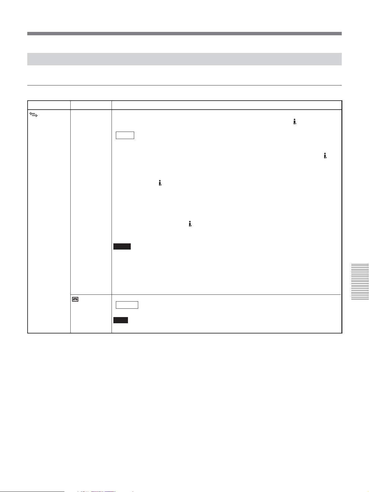
Menu Contents
Initial settings are indicated with rectangles.
IN/OUT REC menu
Icon/Menu Submenu Setting
IN/OUT REC
HDV/DV SEL
(page 34, 44,
54, 62)
Normally, set this menu to [AUTO]. Select this menu when you want to limit the output
format during tape playback or limit the signals to be input or output from
This setting will affect analog outputs.
AUTO : Automatically switches signals to HDV format or DVCAM/DV format
HDV : Outputs portions of signals recorded in HDV format during tape playback.
DV : Outputs signals of portions recorded in DVCAM/DV format during tape
Notes
• Before changing the setting, be sure to disconnect the i.LINK cable, or turn the other
device off. If an i.LINK cable is connected when you change the setting, the video
equipment may not recognize the signals correctly.
• If you select [AUTO], the screen turns off temporarily when HDV signals are switched to
DVCAM/DV signals or vice versa. The video and audio also stops at the same time.
• For details on the i.LINK output and the recording tape format,
HDV/DV jack.
during tape playback.
When the i.LINK cable is connected, the signals in HDV format or
DVCAM/DV format will be switched automatically and signals from
HDV/DV jack will be input /output for recording/playback.
When the i.LINK cable is connected, only the signals in HDV format from
HDV/DV jack will be input/output for recording/playback. Also, select
this setting when the unit is connected to the i.LINK cable to a computer
supporting HDV format
playback.
When the i.LINK cable is connected, only the signals in DVCAM/DV
format from
Also select this setting when the unit is connected to the i.LINK cable to a
computer that supports DV format
HDV/DV jack are input or output for recording/playback.
(see page 44, 54)
(see page 44, 54)
.
.
see pages 96 and 97.
REC MODE
Switches the recording mode between DVCAM and DV format (SP mode only).
DVCAM : Records in DVCAM format.
DV SP : Records in DV format (SP mode).
Note
You cannot change the setting during recording.
Chapter 5 Adjusting and Setting Through Menus
(Continued)
Chapter 5 Adjusting and Setting Through Menus 67
Page 68
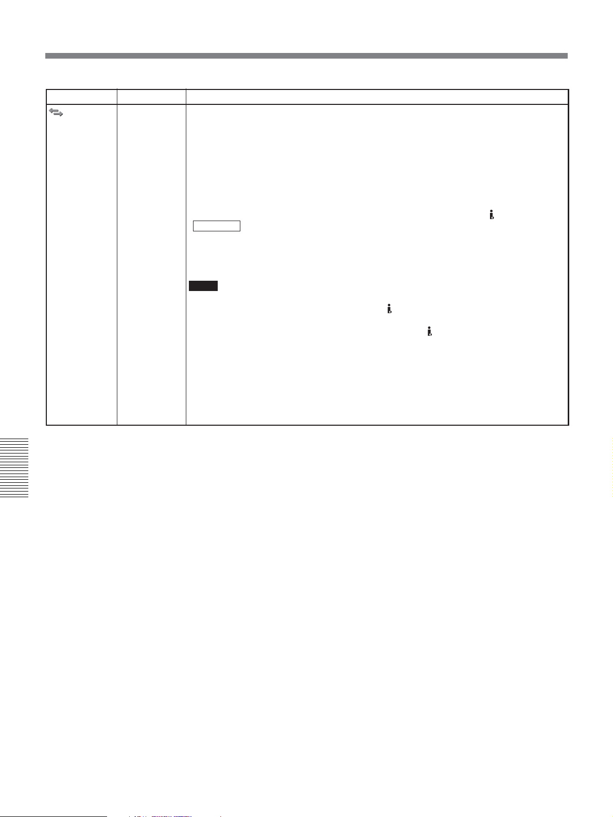
Operating the Menus
Icon/Menu Submenu Setting
IN/OUT REC
VIDEO OUT
Selects the mode of the video output jacks.
HDMI/CMPNT
Selects the output format from HDMI OUT jack and COMPONENT OUT jacks.
Select from [480i], [480p/480i], [1080i/480i], or [720p/480i] when [60i/50i SEL] in
[OTHERS] menu is set to 60i.
Select from [576i], [576p/576i], [1080i/576i], or [720p/576i] when [60i/50i SEL] in
[OTHERS] menu is set to 50i.
DOWN CONVERT
Selects the setting for down converting images output from HDMI OUT jack and analog
video jacks when playing back HDV format or inputting HDV signals from
SQUEEZE : Maintains the image vertically and horizontally by compressing the
LETTER BOX : Maintains the image vertically by compressing the vertical ratio.
EDGE CROP : Maintains the original image size and crops the left and right edges of
Notes
• When you play back an HDV-formatted tape with copyright protected signals, or input
HDV format with copyright protected signals to
will output pictures in either 480i or 576i format.
• Regardless of the playback tape or of the format input to HDV/DV jack, the selectable
setting values displayed on this menu vary depending on the setting of [60i/50i SEL].
• WSS (Wide Screen Signaling) is not output, when the picture is output to COMPONENT
OUT jacks in 480p or 576p. Set the monitor according to the down convert format of the
picture, which is output from the unit.
• When you play back a tape in DVCAM (DV) format while an EE picture in NTSC/PAL is
displayed, the 480i resolution or the 576i resolution is output, regardless of the setting of
[HDMI/CMPNT].
HDV/DV jack.
horizontal ratio. Images appear vertically long.
the images.
HDV/DV jack, COMPONENT OUT jacks
Chapter 5 Adjusting and Setting Through Menus
68 Chapter 5 Adjusting and Setting Through Menus
Page 69
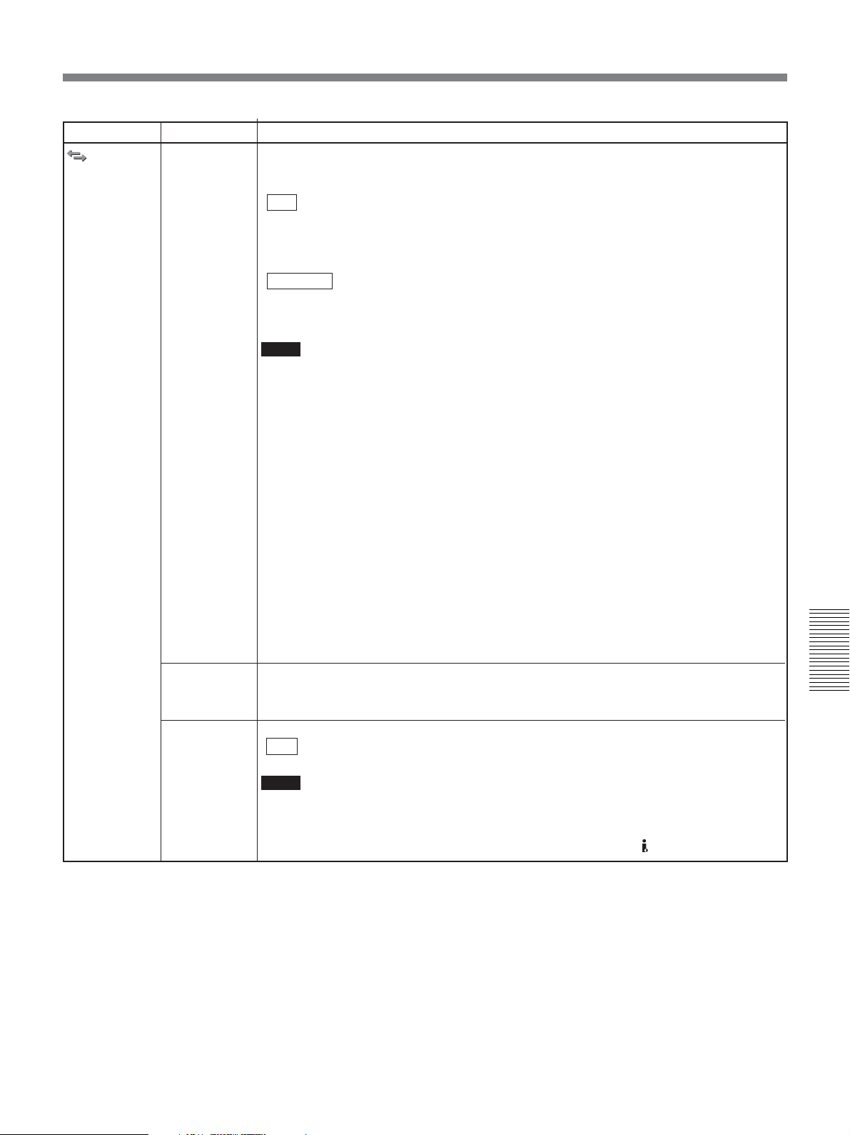
Icon/Menu Submenu Setting
IN/OUT REC
i.LINK SET
(pages 34, 54)
Adjusts the down conversion format. This menu is available when [HDV/DV SEL] is set to
[AUTO] or [HDV].
HDV t DV CONV
OFF : Disables down conversion.
DVCAM : Down converts to DVCAM format.
DV SP : Down converts to DV SP format.
DOWN CONVERT
This setting is available when [HDV t DV CONV] is set to [DVCAM] or [DV SP].
SQUEEZE : Plays back with compressed horizontal screen image and maintains all
EDGE CROP : Plays back with both left and right sides of the screen images cut off and
Notes
• When [DVCAM] is selected, there are some limitations described below.
– ATN (Absolute Track Number) outputs the value counted in DVCAM format during
playback at regular speed (×1) or recording of the internal color bars only.
During playback at irregular speeds other than described above, ATN outputs the value
of a tape recorded in HDV format.
– When the unit is playing back at regular speed (×1) while detecting a blank portion on
the tape, the unit counts the blank portion as ATN-formatted in DVCAM.
– When using the duplicating function that is equipped with a device such as the DSR-25/
45/50, select [DVCAM].
– Please note that a duplicated tape and the source tape recorded in HDV format with
[DVCAM] selected do not share the same ATN (Time code value is displayed
correctly).
• When you change the video format setting of [DOWN CONVERT] of [i.LINK SET] in [IN/
OUT REC] menu, the video signal output from COMPONENT OUT jacks, S VIDEO OUT
jack, or VIDEO OUT jack may be distorted for a moment.
• Before changing your setting, be sure to disconnect the i.LINK cable. If you change the
setting while i.LINK is connected, the video device may not recognize the new setting.
• When you select [EDGE CROP], the outputs of S VIDEO and VIDEO are limited.
For details,
images on display. Images appear vertically long.
maintains the original image appearance.
see page 85
.
CROP
ADJUST
(page 41)
CROP
MARKER
(page 41)
Adjusts the position of edge cropping when down converting 16:9 to 4:3 aspect ratio.
Adjusts the position of the crop marker by pressing K/k buttons to move either left or
right, and press EXEC button to finish. (You can also use J/j buttons.)
Selects whether to display EDGE CROP MARKER or not.
OFF : Does not display the crop marker.
ON : Displays the crop marker.
Notes
• This setting is only available, when [DOWN CONVERT] of [VIDEO OUT] or [i.LINK SET] in
[IN/OUT REC] menu is set to [EDGE CROP].
• EDGE CROP MARKER is displayed when HDV-formatted tape is played back. EDGE
CROP MARKER is also displayed when HDV signals are input to
HDV/DV jacks.
(Continued)
Chapter 5 Adjusting and Setting Through Menus
Chapter 5 Adjusting and Setting Through Menus 69
Page 70
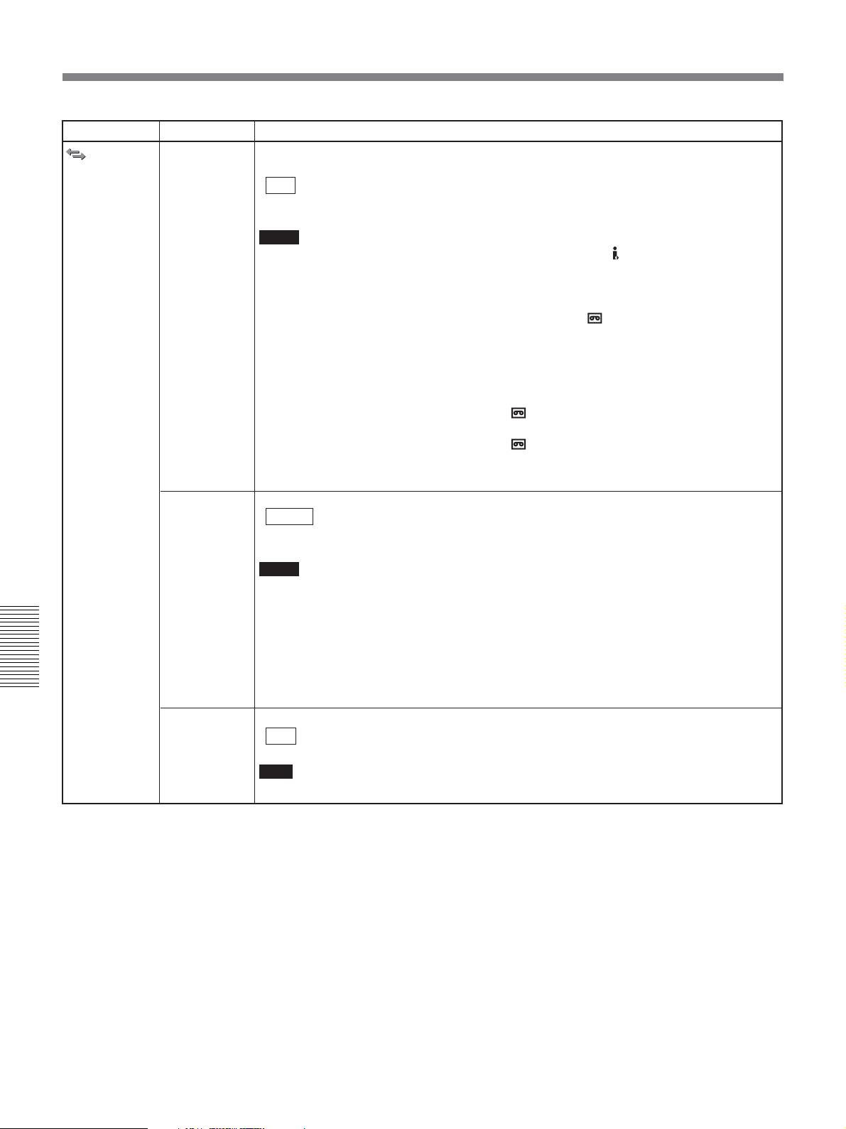
Operating the Menus
Icon/Menu Submenu Setting
IN/OUT REC
COLOR BAR
Selects whether to display color bars or not. Also, you may select color bars with or without
tone signals (1 kHz full bit –20 dB at 60i, 1 kHz full bit –18 dB at 50i).
OFF : Does not display color bars and no tone signals.
ON : Displays color bars without tone signals.
ON [TONE] : Displays color bars with tone signals.
Notes
• Color bars and tone signals are output from HDMI OUT jack, HDV/DV jack, and analog
output jacks.
• Color bars and tone signals cannot be output when the tape is in playback mode.
• The color bars output to i.LINK/the color bars and tone signals recorded on tapes/the
format of tone signals can be set by [HDV/DV SEL] and [
– When [HDV/DV SEL] is set to [AUTO], the format of the color bar and tone signals will
be output/recorded according to the video format displayed in “1 Format indicator”
(page 25)
– When [HDV/DV SEL] is set to [HDV], color bars and tone signals are output/recorded in
HDV format.
– When [HDV/DV SEL] is set to [DV] and [
to [DVCAM], color bars and tone signals will be output/recorded in DVCAM format.
– When [HDV/DV SEL] is set to [DV] and [ REC MODE] in [IN/OUT REC] menu is set
to [DV SP], color bars will be output/recorded in DV (SP) format.
• When the unit turns off and on again, [COLOR BAR] is automatically set to [OFF].
REC MODE].
of text data display on a monitor.
REC MODE] in [IN/OUT REC] menu is set
BARS TYPE
Chapter 5 Adjusting and Setting Through Menus
DV BARS
Selects the type of color bars.
TYPE 1 : Outputs TYPE 1 color bars.
TYPE 2 : Outputs TYPE 2 color bars.
TYPE 3 : Outputs TYPE 3 color bars.
Notes
• When color bars are output in NTSC (60i) mode on the unit, no-setup (0 IRE) signals are
output.
• Even when the unit’s screen aspect ratio displays 4:3, the color bars are generated as
16:9. To output the edge crop (4:3) in HDV format, select [TYPE 1].
• Color bars on the unit are generated in HDV (1080i) resolution. When a resolution other
than HDV (1080i) is output, the color bars are down converted and output. The transition
edges between the color bars are distorted.
• You cannot change the current setting during recording.
Selects the aspect ratio of color bars set in [BARS TYPE] (DVCAM/DV (SP) format only).
16:9 : Sets the aspect ratio of color bars to 16:9.
4:3 : Sets the aspect ratio of color bars to 4:3.
Note
You cannot change the current setting during recording.
70 Chapter 5 Adjusting and Setting Through Menus
Page 71
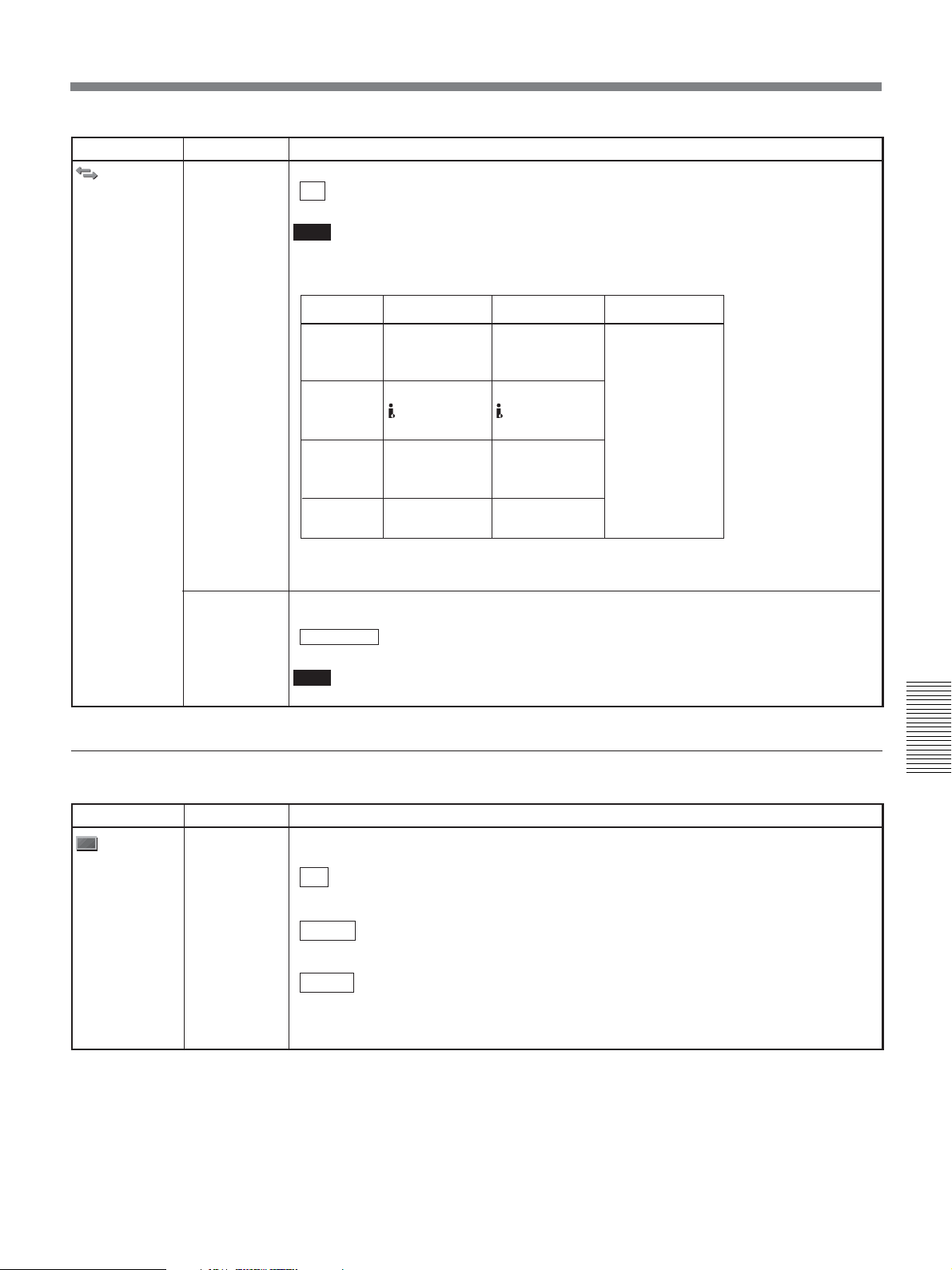
Icon/Menu Submenu Setting
IN/OUT REC
EE/PB SEL
(page 14)
Sets the stop, fast-forward and rewind modes.
EE : Outputs EE picture and EE sound.
PB : Mutes the image and sound.
Note
If this item is set to PB, the output from the unit will be as follows when you press any of the
REC, DUPLICATE PLUS, or AUDIO DUB buttons separately when the unit is stopped
(unless the cassette has been write-protected).
REC button
DUPLICATE
PLUS
button
AUDIO
DUB
button
No button
is pressed
a) Set AUDIO OUTPUT SELECT switch appropriately.
b) When INPUT SELECT switch is set to HDV/DV.
EE picture of
the input image
Image input to
b)
Mute screen
(black)
Mute screen
(black)
Image
HDV/DV jack
Sound
EE sound of the
input sound
(CH-1/2)
a)
Sound input to
HDV/DV jack
EE sound of the
input sound
(CH-3/4)
a)
Mute
(no sound)
Time code
(See page 53)
480i LEVEL
Selects the component output level of luminance and chrominance from either BETACAM
or SMPTE signals when the component output is set to 480i.
BETACAM : Sets COMPONENT OUT jacks to BETACAM level.
SMPTE : Sets COMPONENT OUT jacks to SMPTE level.
Note
For details on COMPONENT OUT jacks specifications,
DISPLAY SET menu
Icon/Menu Submenu Setting
DISPLAY
SET
COUNTER
SET
Selects the appearance of the time counter.
DISPLAY
ON : Enables the time counter display.
OFF : Disables the time counter display.
SIZE
LARGE : Displays the time counter in large letters.
SMALL : Displays the time counter in small letters.
COLOR
TYPE 1 : Displays the time counter with color type 1.
TYPE 2 : Displays the time counter with color type 2.
TYPE 3 : Displays the time counter with color type 3.
TYPE 4 : Displays the time counter with color type 4.
see page 100.
Chapter 5 Adjusting and Setting Through Menus
(Continued)
Chapter 5 Adjusting and Setting Through Menus 71
Page 72
Operating the Menus
Icon/Menu Submenu Setting
DISPLAY
SET
MARKER
BURN
(page 42)
ALLSCAN
MODE
Selects whether to output MARKER BURN or not.
OFF : Does not output MARKER BURN.
ON : Outputs MARKER BURN.
Note
There are some limitations to output MARKER BURN. For details,
Reduces the image on LCD panel to check the area surrounding the picture frame where
the monitors can not display.
OFF : Disables the ALLSCAN MODE.
ON : Enables the ALLSCAN MODE.
Notes
• ALLSCAN MODE is for HDV format only. ALLSCAN MODE does not activate when
DVCAM and DV(SP)-formatted tapes are played.
• If formats are mixed on a tape, the part where the format has changed on a tape cause
distortion of images.
• When [ON] is selected and the output level of COMPONENT OUT is set to 480i, 576i,
480p/480i, or 576p/576i, output images from S VIDEO OUT jack and VIDEO OUT jack
down converts to letter box. For details,
• Once the unit turns off, the setting of [ALLSCAN MODE] sets to [OFF] automatically.
• When you set [MARKER BURN] and [ALLSCAN MODE] in [DISPLAY SET] menu to [ON]
at the same time, the marker will not appear in the correct position on LCD monitor. This is
not a malfunction. The marker will be output correctly via each video jack.
see page 85
see page 42
.
.
DATA CODE
(page 36)
LETTER SIZE
DATE
DISPLAY
Chapter 5 Adjusting and Setting Through Menus
TIME
DISPLAY
REMAINING
(page 26)
Selects whether or not to display the data codes on the analog video output.
OFF : Does not display the data codes.
DATE: Displays the date and time when recorded.
CAMERA DATA
Selects the letter size of the menu at the cursor.
NORMAL : Normal size
2 x : Double height size
Selects the date display in the search screen, the data code display, etc.
Y/M/D : Displays YY/MM/DD (year/month/day).
M/D/Y: Displays MM/DD/YY (month/day/year).
D/M/Y: Displays DD/MM/YY (day/month/year).
Selects the time display in the search screen, the data code display, etc.
12H : Displays 12-hour time. (Default setting for 60i as the factory setting.)
24H : Displays 24-hour time. (Default setting for 50i as the factory setting.)
AUTO : The remaining tape time is displayed for 8 seconds under the following
ON : Always displays the remaining tape time.
: Displays the camera data.
(Default setting for HVR-M25U/M25N.)
(Default setting for HVR-M25E/M25P.)
conditions.
– If the remaining tape time is determined when you turn on power while
a cassette is loaded in the unit.
– When you press PLAY button.
Always displays under the following conditions.
– Fast forward, rewind
– Fast forward during playback, rewind during playback
LCD BRIGHT
LCD COLOR
Adjusts LCD monitor brightness. Press J/j buttons and EXEC button to adjust the
brightness. (The mark under the bar is the factory setting value.)
Adjusts the color density of LCD monitor. Press J/j buttons and EXEC button to adjust the
brightness. (The mark under the bar is the factory setting value.)
72 Chapter 5 Adjusting and Setting Through Menus
Page 73
Operating the Menus
Icon/Menu Submenu Setting
DISPLAY
SET
LCD BLACK
AUDIO SET menu
Icon/Menu Submenu Setting
AUDIO SET
AUDIO MODE
(page 27)
AUDIO MONI
(page 27)
AUDIO LOCK
JOG AUDIO
(page 38)
Mutes the images on LCD panel and display only the text data.
OFF : Does not mute the images
ON : Mutes the images
Note
When [ON] is selected, the images output from the rear panel to the external monitor does
not mute.
Selects the audio mode.
FS32K : Switches the audio mode to 4-channel mode (12-bit mode).
FS48K : Switches the audio mode to 2-channel mode (16-bit mode). (This setting
Notes
• When signals are input from HDV/DV jack, the audio mode of the signals to be recorded
is the same as that of the input signals.
• Recording performs automatically in [FS48K] mode in HDV format.
• You cannot change the current setting during recording.
• Noise may occur at the instant you switch the audio mode.
• When dubbing a sound source in DVCAM, select [FS32K].
Sets the audio that is output from PHONES jack and HDMI OUT jack.
CH1,CH2 : Outputs CH1 and CH2 audio to each channel.
CH1 : Outputs CH1 audio to CH1/2.
CH2 : Outputs CH2 audio to CH1/2.
Note
When AUDIO OUTPUT SELECT switch is set to CH3/4, [CH1] and [CH2] are correspond to
[CH3] and [CH4], respectively. When it is set to MIX, [CH1] and [CH2] are correspond to
CH1/3 synthesis sound and CH2/4 synthesis sound, respectively.
UNLOCK MODE
LOCK MODE : Synchronizes the sampling clocks of the audio and video for recording.
Notes
• You can set this menu when recording in DV format (SP mode) only.
• When recording in HDV or DVCAM format, the menu is set to [LOCK MODE].
• During the i.LINK input, the same setting as that of an input signal is selected regardless
of this setting.
Selects either to turn the sound output on or off when the tape is played at a speed other
than normal. (Available in DVCAM/DV format only.)
OFF : Does not output the sound when playing a tape at a speed other than
ON: Outputs the sound when playing a tape at a speed other than normal.
Notes
• When a tape recorded in HDV format is played back, the sound cannot be output in
various speeds.
• Even if you have set this item to ON, the sound may not be output or may be interrupted
depending on the recording format or tape conditions.
records the sound in all audio ranges, providing a high-quality sound
recording.)
Chapter 5 Adjusting and Setting Through Menus
: Records the sampling clocks of audio and video independently. This
mode applies to a consumer DV tape.
This setting is effective for digital processing and performs a clean splice
during the audio editing process.
normal.
Chapter 5 Adjusting and Setting Through Menus 73
Page 74
Operating the Menus
VTR SET menu
Icon/Menu Submenu Setting
VTR SET
DUPLICATE
PLUS
(page 56)
Selects the video format and whether to use auto rewind or not while duplication.
FORMAT SEL
ALL : Duplicates all video formats.
HDV1080i : Duplicates HDV1080i format only.
DVCAM : Duplicates DVCAM format only.
DV SP : Duplicates DV (SP) format only.
AUTO REW
ON : Rewinds the tape on both the player and the recorder, and starts
OFF : Starts duplicating from the current portion of the tape.
Note
You cannot use these settings during duplication.
duplication. Also, when you continue to duplicate a resource tape from
multiple tapes, the new work tape will be rewound automatically and start
duplication.
CUSTOM
REPEAT
(page 39)
Chapter 5 Adjusting and Setting Through Menus
AUTO INDEX
(page 47)
STILL PICT
Adjusts the REPEAT TIMES, REPEAT CYCLE, and START TIME of the CUSTOM
REPEAT.
REPEAT TIMES
ON/OFF : Selects whether to apply REPEAT TIMES setting or not.
TIMES : Sets the number of times to repeat playbacks.
Set the number by pressing J/j buttons on the unit.
REPEAT CYCLE
ON/OFF : Selects whether to apply REPEAT CYCLE setting or not.
CYCLE : Sets the time of intervals for playback.
Set the number by pressing J/j buttons on the unit.
START TIME
ON/OFF : Selects whether to apply START TIME setting or not.
TIME : Sets the starting time of CUSTOM REPEAT.
Set the number of each hour and minute by pressing J/j buttons on the unit.
Press K/k buttons to switch between hour and minute. Press EXEC button to execute.
Selects whether or not to mark an index signal automatically when the unit in the stop mode
starts recording.
ON : Marks an index signal at the beginning of the recording.
OFF: Does not mark an index signal at the beginning of the recording.
Selects the image displayed in the still mode (DVCAM/DV (SP) format only).
AUTO : Displays an optimized image according to the movement in the image.
FRAME: Displays a frame image.
FIELD: Displays a field image.
Notes
• If you select [FIELD], the image of field 2 is displayed.
• When a tape has been recorded in HDV format, a field image is always displayed.
FF/REW
SPEED
Selects the tape transport mode in fast-forward and rewind.
FF/REW : Fast-forwards or rewinds the tape at maximum speed without displaying
(page 15)
SHUTTLEMAX
74 Chapter 5 Adjusting and Setting Through Menus
the picture.
: Fast-forwards or rewinds the tape at maximum speed while displaying
the picture.
DVCAM
NTSC: Approx. 14 times of normal speed
PAL: Approx. 17 times of normal speed
HDV/DV(SP)
Approx. 24 times of normal speed
Page 75
Icon/Menu Submenu Setting
VTR SET
STILL TIME
Selects the time to switch to the tape protection mode from the still mode.
30 sec : 30 seconds
1 min : 1 minute
2 min: 2 minutes
3 min: 3 minutes
Notes
• If the unit is left in playback pause mode for a long time, the tape or the video heads may
be damaged or the video heads may become clogged. Select the shortest time possible.
Particularly, when using a Mini-DV cassette that is longer than 60 minutes, select [30
SEC] or [1 MIN].
• When the setting is changed, the first tape protection mode change uses the time setting
from before the settings were changed. From the second tape protection mode change,
the new time setting is used.
FROM STILL
Selects the tape protection mode to change the mode after the time set in [STILL TIME] is
past
STOP : Stops the tape.
STEP FORWARD
Note
If you play a tape recorded in HDV format with [STEP FORWARD] selected, the tape
advances a few frames forward.
FROM REC P
Selects the tape protection mode which the unit changes after the recording has been
paused for more than 3 minutes.
STOP : Stops the tape.
REC PAUSE : Maintains the recording pause mode.
Note
When the recording pause mode continues for a long time after you select [REC PAUSE],
the tape may be damaged or the video heads may be damaged or clogged. If there is no
other reason to do this, select [STOP]. Particularly when you use a Mini-DV cassette that is
longer than 60 minutes, select [STOP].
TC/UB SET menu
Icon/Menu Submenu Setting
TC/UB SET
TC PRESET
(page 50)
Reset the time code value or set the desired time code value.
RESET : Resets the time code value to 00:00:00:00.
PRESET : Sets the desired time code value.
Note
To set the initial time code value, you need to set [TC MAKE] to [PRESET] first. If [TC
MAKE] has been set to [REGENERATE], or [HDV/DV IN TC] has been set to [EXTERNAL],
this setting is not effective.
: Forwards one frame.
Chapter 5 Adjusting and Setting Through Menus
UB PRESET
(page 50)
Resets the user bits value or set the desired user bits value.
RESET : Resets the user bits value to 00 00 00 00.
PRESET : Sets the user bits value. (You can set the user bits as eight-digit
hexadecimal values (0 to 9, A to F) (base 16) to have the date, time,
scene number, and other information inserted into the user bits.)
Note
When INPUT SELECT switch is set to HDV/DV and HDV signals are input to the unit, this
setting is not effective. (When color bar is displaying or recording, this setting is effective.)
(Continued)
Chapter 5 Adjusting and Setting Through Menus 75
Page 76
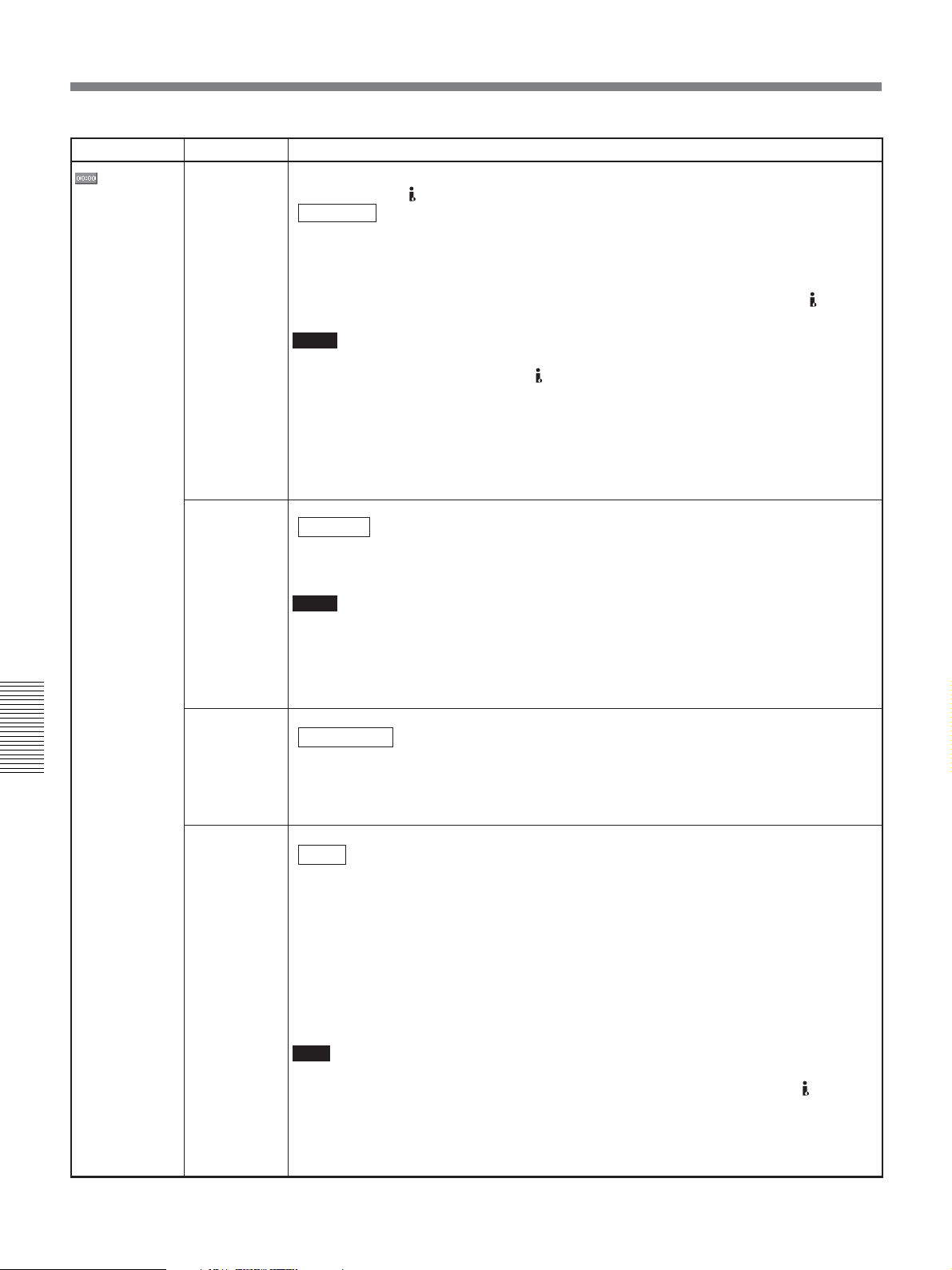
Operating the Menus
Icon/Menu Submenu Setting
TC/UB SET
HDV/DV IN
TC
(page 49)
Selects whether to record internal time code or external time code while the unit records the
signals input from HDV/DV jack.
INTERNAL : Records the time code generated by the internal time code generator. (If
EXTERNAL: Records the time code with video and audio signals input from
Notes
• When this item is set to [EXTERNAL], INPUT SELECT switch on the front panel is set to
HDV/DV, and no signal is input from
(—:—:—:—) are recorded as time code. At the point that inputting of a signal begins, the
time code of that signal will be recorded.
• If you set this item to [EXTERNAL] and the external time code input is discontinuous or
does not advance correctly, recording or displaying the time code on the unit may not be
done correctly. If there is a discontinuous time code on your recorded tape, you may not
edit or search correctly, depending on the device used to edit.
[TC MAKE] is set to [REGENERATE] and no time code is recorded on
the tape, the unit records time code from 00:00:00:00. If there is time
code already recorded on the tape, the unit records continuous time code
from this point.)
HDV/DV
jack.
HDV/DV jack, if you start recording, bars
TC RUN
(page 51)
TC MAKE
(page 51)
Chapter 5 Adjusting and Setting Through Menus
TC FORMAT
(page 52)
Selects the advancement mode (counting up).
REC RUN : Time code value advances only while recording.
FREE RUN : Time code value advances even when the unit is not recording.
(Use this setting to adjust the initial value of the time code to the present
time.)
Notes
• If you set the advancement mode to [FREE RUN], the time code will be updated by the
internal clock when the power is off. Therefore, when you turn on the unit again, the time
code may have been delayed or advanced somewhat.
• If the internal backup battery is exhausted, the time code of [FREE RUN] setting is
initialized.
Selects the time code when you start recording.
REGENERATE
PRESET : The time code starts from the value set in [TC PRESET] in [TC/UB SET]
Selects the recording mode of the time code when 60i format is used.
AUTO : Automatically sets the mode in accordance with the mode already set on
DF : Selects the drop frame mode.
NDF : Selects the non-drop frame mode.
Note
When [60i/50i SEL] is set to [50i], the unit operates as a 50i specification model. Therefore,
the time code is set to the non-drop frame mode. Even if 60i signals are input to HDV/DV
jack when [60i/50i SEL] is set to [50i], the time code generated by the unit is in the non-drop
frame mode regardless of [TC FORMAT] setting. To set the time code in the drop frame
mode, set [60i/50i SEL] to [60i]. As a result, [TC FORMAT] setting will return to the status
before [60i/50i SEL] menu was set to [50i].
: The time code value is set to continuous time code from the one already
recorded on the tape. If no time code is recorded on the tape, it starts
from 00:00:00:00.
menu.
a cassette tape. (If nothing is recorded on the tape, the non-drop frame
mode is set. If the unit cannot correctly read the frame mode on the tape,
it will use the frame mode that was set in the last position on the tape
that the unit can read correctly. If you remove the cassette, the mode of
the last position that the unit was able to read correctly is cleared and the
non-drop frame mode is set when recording is restarted from the same
position.If [TC MAKE] is set to [PRESET], the non-drop frame mode is
set.)
76 Chapter 5 Adjusting and Setting Through Menus
Page 77
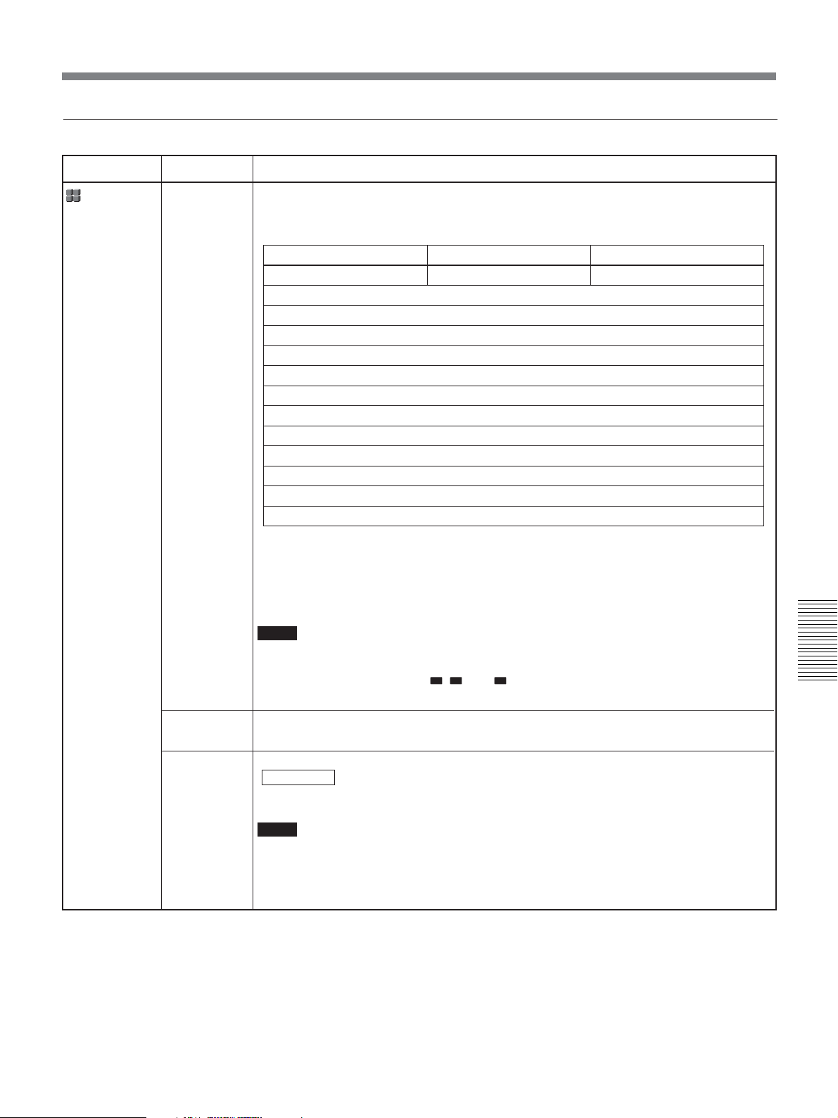
OTHERS menu
Icon/Menu Submenu Setting
OTHERS
ASSIGN BTN
(pages 11, 12,
14)
Assigns a function other than the default functions to ASSIGN buttons (INDEX (A1) button,
RESET (A2) button, AUDIO DUB (A3) button).
The available functions of each ASSIGN button are as listed below.
a) Default setting
b) Same functions as on REMOTE COMMANDER
c) The above settings can be set with the menu on the unit. For details, refer to the menu items.
END SEARCH: The last five second portion recorded on a tape is played back and stopped. Use
END SEARCH to check the last picture recorded. Once you eject the tape from the unit, you cannot
use this function.
Notes
• The default functions on each ASSIGN buttons can not be assigned to other ASSIGN
buttons.
• If you assign other functions, A1, A2, and A3 will be displayed on left corner of the Data
display screen.
INDEX (A1) button RESET (A2) button AUDIO DUB (A3) button
INDEX WRITE
a)
COUNTER RESET
HDV t DV CONV
HDMI/CMPNT
a)
c)
c)
AUDIO DUB
a)
END SEARCH
DATA CODE
ALLSCAN MODE
COLOR BAR
SEARCH SELECT
SEARCH +
SEARCH –
COUNTER SIZE
COUNTER COLOR
FF/REW SPEED
b)
c)
c)
b)
b)
b)
c)
c)
c)
Chapter 5 Adjusting and Setting Through Menus
LANGUAGE
COMMANDER
(page 24)
You can select the desired language on Data display screen. You can choose Simplified
English if your native language is not available among the options.
Selects the control device.
WIRELESS : Enables the control of Remote Commander.
CONTROL S: Enables the control of the remote control unit DSRM-10 (not supplied)
connected to CONTROL S IN jack. (Remote Commander is disabled.)
Notes
• The unit accepts signals from any Sony Remote Commander whose command mode is
set to VTR4, not only the supplied one. To disable the control from any Remote
Commander, set this item to CONTROL S.
• You can use the DSRM-20 (no longer manufactured: not supplied).
(Continued)
Chapter 5 Adjusting and Setting Through Menus 77
Page 78
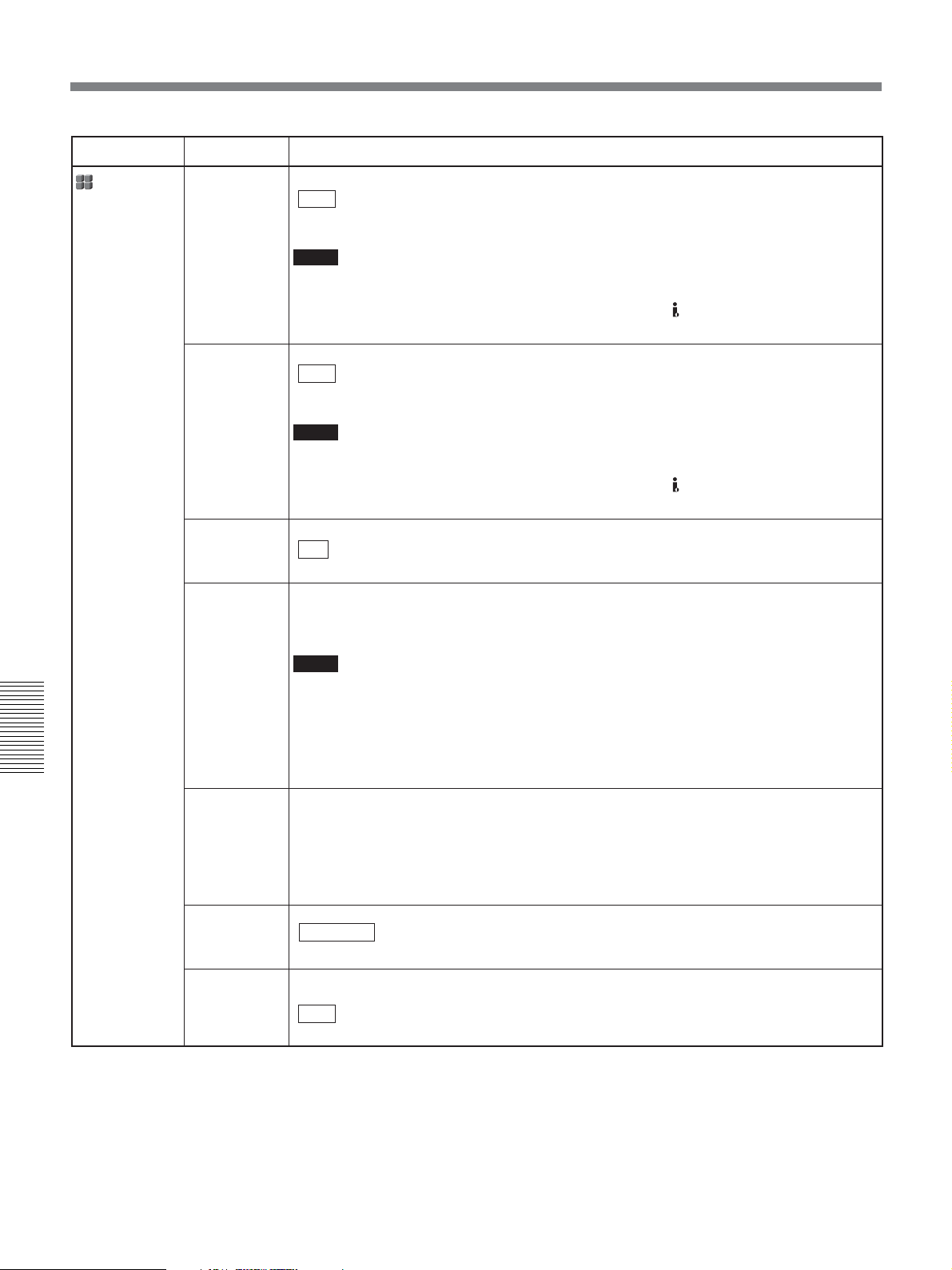
Operating the Menus
Icon/Menu Submenu Setting
OTHERS
PB YNR
Selects the noise reduction level for the luminance signals when a tape is played.
OFF : No noise reduction
LOW : Low noise reduction
HIGH : High noise reduction
Notes
• When you use noise reduction, there may be an afterimage depending on the condition of
the picture.
• Noise reduction is also available with pictures output from
when dubbing and editing a picture in HDV/DV.
HDV/DV jack. Use caution
PB CNR
BEEP
CLOCK SET
Chapter 5 Adjusting and Setting Through Menus
HOURS
METER
(page 92)
Selects the noise reduction level for the chrominance signals when a tape is played.
OFF : No noise reduction
LOW : Low noise reduction
HIGH : High noise reduction
Notes
• When you use noise reduction, there may be an afterimage depending on the condition of
the picture.
• Noise reduction is also available with pictures output from
when dubbing and editing a picture in HDV/DV.
Selects whether or not the unit beeps.
ON : Enables the beep.
OFF : Disables the beep.
1 Press J/j buttons to adjust the number, then press K/k buttons to set the month,
day, hour, and minute.
2 Press EXEC button to execute.
Notes
• 12:00 AM stands for midnight and 12:00 stands for noon when [TIME DISPLAY] is set to
[12H].
• If you do not use the unit for 3 months or more, the built-in rechargeable battery will
become completely discharged, and the settings of the day and the time may be cleared
from the memory. In this case, charge the built-in rechargeable battery and set the clock
(page 92).
again
Displays the accumulated time counts (by the digital hours meter) in units of 10 hours or 10
counts.
OPERATION : Power on duration
DRUM RUN: Drum rotation duration
TAPE RUN: Tape run duration
THREADING: Tape unthreading count
HDV/DV jack. Use caution
AC ON MODE
AUTO
STANDBY
Switches the state into which the unit goes when the unit is connected to the AC outlet.
STANDBY : Makes the unit go into the standby mode.
ON: Turns the unit on.
Selects whether the unit goes into the standby mode or not, if the unit has been in the stop
mode and no key operations have been attempted for more than one hour.
OFF : Leaves the unit in the stop mode.
ON: Makes the unit go into the standby mode.
78 Chapter 5 Adjusting and Setting Through Menus
Page 79
Icon/Menu Submenu Setting
OTHERS
60i/50i SEL
(page 45)
Switches to 1080/60i (NTSC) or 1080/50i (PAL).
1 Press J/j buttons to select [YES], then press EXEC button.
2 Press J/j buttons to select [YES] again, then press EXEC button.
60i/50i SEL
Change to 50i?
Reboots
after change.
YES
NO
INITIALIZE
Resets the menu to preset settings except CLOCK SET.
1 Press J/j buttons to select [YES], and then press EXEC button.
INITIALIZE
Reset all settings
except "CLOCK SET"
to defaults.
YES
NO
2 Press J/j buttons to select [YES] again , then press EXEC button.
Chapter 5 Adjusting and Setting Through Menus
Chapter 5 Adjusting and Setting Through Menus 79
Page 80
Maintenance
Troubleshooting
Please check the following before contacting your Sony dealer.
General Operation Troubles
Symptom Cause/Remedy
A menu item is not available.
• The KEY INH switch is set to ON.
t First, set the switch to OFF, then adjust the menu.
• There are menus that cannot be used depending in [IN/OUT REC] menu setting.
t Change [IN/OUT REC] menu settings
• Some menu items are only available in EE mode or playback mode.
t Set the unit to EE mode or playback mode.
• Some menu items are only available when the tape is inactive.
• There are some menus you cannot use without setting the clock.
(page 67)
Chapter6
.
Some menu item settings change
accidentally.
The unit operates by itself.
Chapter 6 Maintenance
The supplied wireless Remote
Commander does not work.
Even though the settings on the unit are
correct, you cannot make the unit record
using the Remote Control Unit DSRM-10
(not supplied).
Even though KEY INH switch is set to ON,
the unit responds to operations input
using Remote Commander.
80 Chapter 6 Maintenance
• You have pulled out the power cord during a menu operation or LCD monitor
brightness adjustment.
t Adjust the menu again. To prevent this incident recurring, do not pull out the
plug while adjusting the menu or the brightness of LCD monitor.
• [COMMANDER] in [OTHERS] menu is set to WIRELESS and a Sony Remote
Commander whose command mode is set to VTR4 is operated near the unit.
t Set [COMMANDER] to [CONTROL S].
• When TIMER switch is set to REPEAT and [START TIME] of [CUSTOM
REPEAT] in [VTR SET] menu is set to [ON], the unit starts to repeat playbacks
at the start time you have set.
t Set TIMER switch to OFF, or turn [START TIME] to [OFF].
t Set [COMMANDER] in [OTHER] menu to [WIRELESS].
t On the Remote Control Unit DSRM-10, press PLAY button while holding REC
button down.
• Setting KEY INH switch to ON does not disable Remote Commander. To
disable the control of the Remote Commander, set [COMMANDER] in
[OTHERS] menu to [CONTROL S].
Page 81
Symptom Cause/Remedy
Whenever you connect the unit to an AC
outlet, the unit turns on automatically.
• [AC ON MODE] in [OTHERS] menu is set to [ON].
t Set [AC ON MODE] to [STANDBY].
• There is a cassette inside the unit and TIMER switch is set to REPEAT or REC.
t Set TIMER switch to OFF.
No picture on LCD monitor.
• [LCD BLACK] in [DISPLAY SET] menu is set to [ON].
t Set it to [OFF].
• With an analog connection, the current setting of [60i/50i SEL] in [OTHERS]
menu is not appropriate.
t Set it to the appropriate position for the device you are using.
Power sources
Symptom Cause/Remedy
The power cannot be turned on.
The unit will not operate even if the power
has been turned on.
• AC power cord is disconnected.
t Connect the AC power cord.
• KEY INH switch is set to ON.
t Set the switch to OFF.
• KEY INH switch is set to ON.
t Set the switch to OFF.
• Moisture condensation has occurred
• The cassette is not inserted straight.
t Eject and reinsert it straight.
t Disconnect the power supply and then reconnect it after about 1 minute. If the
unit does not operate even after you reconnect the power, use a sharp-tipped
ballpoint pen or similar tool to press RESET button. When you press RESET
button, all settings including the date, time, and 60i/50i are initialized.
(page 91)
.
Cassette tapes
Symptom Cause/Remedy
The cassette cannot be inserted.
It takes time to eject the cassette.
A cassette tape cannot be removed.
The cassette tape is not ejected when you
press EJECT button.
• There is moisture condensation on the head drum
t With the unit powered on, wait more than one hour.
• The cassette is not inserted straight.
t Eject and reinsert it straight.
• Another cassette has been loaded already.
t Remove the cassette and insert the one you want to load.
• This is not a malfunction.
t The unit ejects the cassette slowly to protect the tape. While the cassette is
being ejected, q (cassette) indicator blinks.
t Check whether the power supply is connected properly.
• Moisture condensation has occurred in the unit
(page 91)
(page 91)
.
.
Chapter 6 Maintenance 81
Chapter 6 Maintenance
(Continued)
Page 82
Troubleshooting
Symptom Cause/Remedy
The cassette memory data and title are
not displayed when using a cassette tape
with the cassette memory function.
• The unit does not support the cassette memory function and therefore such data
is not displayed.
The remaining tape time is not displayed.
t To always display the remaining tape time, set [
SET] menu to [ON].
Output/Playback
Symptom Cause/Remedy
Cannot playback.
Cannot playback in reverse at various
speeds.
Horizontal lines are displayed on an
image.
An image has block noise.
An image is blurred or not displayed.
No picture is output via HDV/DV jack.
t If a tape has reached its end, rewind the tape.
• The unit cannot play back a tape recorded in HDV format in the reverse
direction at various speeds
• The video heads are dirty.
t Clean the video heads using the supplied cleaning cassette.
•A damaged tape is loaded.
t Remove the cassette and insert another one.
• You have tried to make the unit play back a tape recorded in LP mode of DV
format.
t The unit can play back only tapes recorded in HDV, DVCAM format or in SP
mode of DV format. A tape recorded in LP mode of DV format cannot be
played back on the unit.
t Reconnect the i.LINK cable (not supplied).
• INPUT SELECT switch is set to a position other than HDV/DV.
t Set the switch to HDV/DV.
(page 37)
REMAINING] in [DISPLAY
.
EE picture and EE sound are not output.
The audio breaks up.
Chapter 6 Maintenance
Duplication does not function.
Cannot perform a date search and index
search.
The time code is not reset to “00:00:00:00”
after rewinding a tape to the recording
starting point.
• [EE/PB SEL] in [IN/OUT REC] menu is set to [PB].
t Set [EE/PB SEL] to [EE].
• The setting of INPUT SELECT switch does not match the signal input.
t Set the switch according to the signal input.
•A damaged tape is loaded.
t Remove the cassette and insert another one.
• The video heads are dirty.
t Clean the video heads using the supplied cleaning cassette.
• You have tried to make the unit play back a tape recorded in LP mode of DV
format.
t The unit can play back only tapes recorded in HDV, DVCAM or DV (SP)
format. A tape recorded in LP mode of DV format cannot be played back on
the unit.
• Check the STOP/CAUTION No. and the warning messages displayed on LCD
monitor. Take the appropriate action
• There is a portion with no recording at the beginning or in the middle of a tape.
This is not a malfunction.
• The time code is not displayed correctly at the starting point of recording. This
condition, however, is not a malfunction. When you restart playback, the time
code and images are displayed correctly from the starting point.
(See page 59)
.
82 Chapter 6 Maintenance
Page 83
Symptom Cause/Remedy
A user bit is not displayed correctly during
fast-forward/rewind.
• When input video signals without a user bit are recorded while HDV is input to
i.LINK, the user bit is not displayed correctly. Either “–– –– –– ––” or “00 00 00
00” is displayed during playback and fast-forward/rewind, respectively.
“– – – – – – ” appears on the date display
(page 36)
.
Although the HDMI cable or component
video cable is connected properly to a
television set or monitor to play back a
tape, no image or audio is output.
When you connect the unit to a 4:3
television set, the displayed image
appears flattened.
Even though [HDV/DV IN TC] in [TC/UB
SET] menu is set to [EXTERNAL], the
time code of the input i.LINK signal is not
recorded.
• The tape has been played back without setting the date and time.
t Set the date and time.
• The tape portion being played back has no recording.
• If there is a scratch or noise on the tape, the data code cannot be read.
t Use the correct setting for [HDMI/CMPNT] in [VIDEO OUT] in [IN/OUT REC]
menu in accordance with the equipment to be connected.
• No audio is output from COMPONENT OUT jacks.
t Connect also an audio cable.
t When you output from HDMI OUT jack and COMPONENT OUT jacks, set
[HDMI/CMPNT] and [DOWN CONVERT] of [VIDEO OUT] in [IN/OUT REC]
menu correctly before play back.
When you output from
HDV/DV jack, set [HDV t DV CONV] and [DOWN
CONVERT] of [i.LINK SET] in [IN/OUT REC] menu correctly before play back.
When you output from S VIDEO jack and VIDEO jack, set [DOWN
CONVERT] of [VIDEO OUT] in [IN/OUT REC] menu correctly before play
back.
t DVCAM/DV tape images recorded in the wide mode are not displayed
properly. Use a widescreen-compatible monitor.
• The i.LINK signal output from the digital non-linear editing controller does not
include a time code.
t Confirm that the editing software you are using is capable of outputting a
time code.
• INPUT SELECT switch is not set to HDV/DV.
t Set it to HDV/DV.
After playing at 1/10 of normal speed in
forward or reverse for more than 1 minute,
normal playback forward starts.
Playback pause mode is released and the
unit goes into the stop mode.
Playback pause mode is released and the
tape forwards for each preset time
interval.
After the unit has been left in the stop
mode and no key operations have been
attempted for more than one hour, the unit
goes into the standby mode (the unit’s
power turns off).
The pause mode of playback, recording,
or audio dubbing is released
automatically.
• To protect a tape, the unit is set to start normal playback after playing at 1/10 of
normal speed in forward or reverse for more than 1 minute.
t Play back the tape at 1/3 of normal speed in forward or reverse.
• To protect the tape, the unit is set to go into the stop mode after the playback
pause mode continues for a certain period.
t Set [FROM STILL] in [VTR SET] menu to [STEP FORWARD]. If you do so,
the tape will forward by one frame for each time interval set in [STILL TIME].
• To protect the tape, the unit is set to forward the tape after the playback pause
mode continues for a certain period.
t Set [FROM STILL] in [VTR SET] menu to [STOP]. If you do so, the unit goes
into the stop mode after the playback pause mode continues for the interval
set in [STILL TIME].
• [AUTO STANDBY] in [OTHERS] menu is set to [ON].
t Set [AUTO STANDBY] to [OFF].
• To protect the tape and the video heads, the unit goes into the stop mode after
the pause mode of recording, audio dubbing, or duplicating continues for more
than 3 minutes.
t To maintain the pause mode, set [FROM REC P] in [VTR SET] menu to
[REC PAUSE].
Chapter 6 Maintenance
(Continued)
Chapter 6 Maintenance 83
Page 84
Troubleshooting
Symptom Cause/Remedy
When the tape is rewound to its beginning,
the playback automatically starts.
• TIMER switch is set to REPEAT.
t Set TIMER switch to OFF.
• You pressed PLAY button while holding REW button down.
t If you do this, the unit rewinds the tape to its beginning and begins playback
(See page 15)
.
During playback, the unit starts rewinding
suddenly.
When the tape reaches its end, rewinding
starts automatically.
The unit does not function as part of a
digital non-linear editing system.
Although the i.LINK cable is connected,
the image from an external equipment is
not displayed.
No image is displayed even though the
video cable is connected correctly.
The image looses color or is distorted
when you play back the tape on a
television set or monitor connected to the
unit.
• TIMER switch is set to REPEAT.
t When TIMER switch is set to REPEAT, the unit starts rewinding at the
moment when a signal for index search or a blank portion is detected. Set
TIMER switch to OFF.
• TIMER switch is set to REPEAT.
t When TIMER switch is set to REPEAT, the unit starts rewinding at the
moment when the end of the tape is detected. Set TIMER switch to OFF.
• INPUT SELECT switch is set to a setting other than HDV/DV.
t Set it to HDV/DV.
• The editing controller or the editing software is not compatible with the unit.
t Refer to the instruction manuals of the controller or the software and consult
their manufacturers.
t Disconnect and then reconnect the i.LINK cable correctly.
• INPUT SELECT switch is set to a setting other than HDV/DV.
t Set it to HDV/DV.
• There are output restrictions for some [HDMI/CMPNT] settings of [VIDEO OUT]
in [IN/OUT REC] menu. For details,
• INPUT SELECT switch setting does not match the cable connected to the unit.
t Set INPUT SELECT switch to S VIDEO or VIDEO to match the cable
connection.
t Connect the unit to a television set or monitor that is compatible with its [60i/
50i SEL] format.
t Set [60i/50i SEL] in [OTHERS] menu, according to the signal-format (page
79).
see page 68
.
is displayed on the screen.
Chapter 6 Maintenance
84 Chapter 6 Maintenance
• This icon is displayed when you playback a tape recorded with 4-channel
microphone recording on another device. This unit does not support 4-channel
microphone recording. (The icon is displayed when you play back a tape
recorded with 4-channel microphone in DVCAM or DV (SP) format. However, it
is not displayed during playback of a tape recorded with 4-channel microphone
in HDV format.)
Page 85
Symptom Cause/Remedy
The output from S VIDEO OUT jack and
VIDEO OUT jack is different from [DOWN
CONVERT] setting of [VIDEO OUT] in [IN/
OUT REC].
The output from S VIDEO jack and VIDEO jack is set as follows.
• When the playback format is set shown below, the output from S VIDEO jack or
VIDEO jack is fixed in EDGE CROP.
Playback format HDV (HDV1080i)
[VIDEO OUT] in
[IN/OUT REC]
[i.LINK SET] in
[IN/OUT REC]
• When the playback format is set shown below, the output from S VIDEO jack or
VIDEO jack is fixed in LETTER BOX.
Playback format
[VIDEO OUT] in [HDMI/CMPNT] 480i, 576i, 480p/480i,
[IN/OUT REC] 576p/576i
[ALLSCAN MODE] in [DISPLAY SET] ON
Menu item Setting
[DOWN CONVERT]
[HDMI/CMPNT] 480p/480i, 576p/576i
[HDV t DV CONV] DVCAM or DV SP
[DOWN CONVERT] Set to EDGE CROP
Menu item Setting
SQUEEZE or
LETTER BOX
HDV (HDV1080i or
HDV720p)
Recording/Dubbing
Symptom Cause/Remedy
Whenever you connect the unit to an AC
outlet, the unit automatically starts
recording.
Even though KEY INH switch is set to ON,
the unit starts recording/playback by itself.
No picture is output via HDV/DV jack.
• TIMER switch is set to REC.
t When TIMER switch is set to REC, the unit starts recording whenever the
power is connected. Set TIMER switch to OFF.
• TIMER switch is set to REPEAT or REC.
t TIMER switch setting has a higher priority than KEY INH switch setting. Set
TIMER switch to OFF.
• When [COMMANDER] in [OTHERS] menu is set to [WIRELESS], the unit
responds to signals from Remote Commander even though KEY INH switch is set
to ON.
t Set [COMMANDER] to [CONTROL S].
t Reconnect the i.LINK cable (not supplied).
• INPUT SELECT switch is set to a position other than HDV/DV.
t Set the switch to HDV/DV.
t Set [HDV/DV SEL] in [IN/OUT REC] menu correctly.
Chapter 6 Maintenance
(Continued)
Chapter 6 Maintenance 85
Page 86
Troubleshooting
Symptom Cause/Remedy
When you set AUDIO INPUT LEVEL
switch:
• You do not know how to adjust the input
level.
• The recorded level is too low.
• The recorded sound is distorted.
Audio dubbing cannot be done.
Audio dubbing is interrupted.
No sound or undesired sound is output
from HDMI OUT jack, AUDIO OUT jacks,
or PHONE jack.
Cannot hearCH3 and CH4 audio.
If an i.LINK cable is connected when you
edit the dubbing, the monitor does not
display any image.
Confirm the level of the sound output from the player by referring to the player’s
instruction manual. According to that output level, set AUDIO INPUT LEVEL
switch on the rear panel of the unit so as to obtain an optimum level.
If you are not clear about the player’s output level, try the following procedures.
1 Specify the output level by types of audio output connectors available on the
player.
• If the player is equipped with phono jacks: –10.
• If the player is equipped with XLR connectors: +4 or –2.
2 Set AUDIO INPUT switch on the front panel to AUTO and play back the tape
which you intend to use for playback. When the playback audio level is at its
maximum, if the audio levels meters exceed 0 dB, set AUDIO INPUT LEVEL
switch to the lower step (+4). Either, set AUDIO INPUT switch to MANU and
turn AUDIO REC LEVEL control knobs to adjust the recording level. The
recorded sound at the portion where the meters exceed 0 dB will be distorted.
• You are trying to dub the sound onto an HDV or DV-formatted tape.
t Sounds can be dubbed only onto a DVCAM-formatted tape (recorded) in the
32 kHz audio mode (4-channel). If the unit detects the following, audio
dubbing will automatically abort, an alarm message will be superimposed on
LCD monitor and on an external monitor.
–A blank portion
–A section recorded in other than 32 kHz audio mode (4-channel)
–A portion recorded in other than DVCAM format
• You have tried to dub the sound onto channels 1/2.
t Only channels 3/4 can be used for dubbing. You cannot dub the sound onto
channels 1/2.
• When the audio mode is set to 32 kHz (4-channel), you can select the audio
channel to output the sound using the AUDIO OUTPUT SELECT selector on the
front panel. Check the setting of [AUDIO MONI] in [AUDIO SET] menu.
t Set AUDIO OUTPUT SELECT switch to MIX or CH-3/4.
t Use the correct setting for [HDV/DV SEL] in [IN/OUT REC] menu in
accordance with the equipment to be connected.
The unit does not function as part of a
digital non-linear editing system.
The functions on the unit do not operate.
Chapter 6 Maintenance
86 Chapter 6 Maintenance
• The INPUT SELECT switch is set to a setting other than HDV/DV.
t Set it to HDV/DV.
• The editing controller or the editing software is not compatible with the unit.
t Refer to the instruction manuals of the controller or the software and consult
their manufacturers.
Page 87
Warning indicators and messages
Self-diagnosis display/Warning Indicators
The following alarm indicators may appear on LCD monitor or an external monitor. For further information about
each symptom and recovery method, see the relevant page indicated in the parentheses.
Message/Alarm Indicator Cause/Corrective Action
C:ss:ss/E:ss:ss
(Self-diagnosis display)
% (Moisture condensation warning)*
Q (Warning indicator pertaining to the
tape)
Z (Eject cassette warning)*
If an error still recurs after you retry the corrective actions several times, contact
Sony Customer Service or your place of purchase.
C:21:ss
t Condensation has occurred. Remove the cassette and insert it again after
approximately 1 hour
(page 91)
.
C:22:ss
t The video head is dirty. Use a cleaning cassette to clean the head
(page 89)
C:31:ss/C:32:ss
t Symptoms other than the above are occurring. Insert a cassette again and
retry the operation. Do not take this action, however, if there is negligible
condensation in the unit
t Unplug the power cord, plug it in again, and then retry the operation.
t Replace the tape.
t Remove the cassette, unplug the power cord, and leave the unit for
approximately 1 hour
(page 91)
(page 91)
.
.
The icon blinks slowly.
• The remaining tape time is less than 5 minutes.
The icon blinks rapidly.
• Condensation has occurred
• The self-diagnostics message is displayed
(page 91)
.
(page 87)
.
.
* An alarm beep will be emitted when an alarm indicator or message is displayed (page 78).
Chapter 6 Maintenance
Chapter 6 Maintenance 87
Page 88
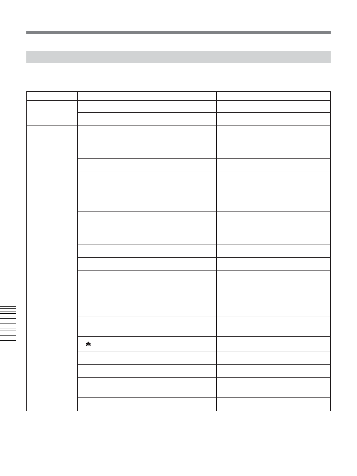
Warning indicators and messages
Alarm Messages
The following alarm messages will appear together with the alarm indicators. Take corrective action according to
the displayed message.
Item Message Cause/Corrective Action
Moisture
condensation
% Z Moisture condensation. Eject the cassette.
% Moisture condensation. Turn off for 1H.
t
See page 91 for details.
t
See page 91 for details.
Cassette/Tape
Audio dubbing
Others
Q Insert a cassette.
Z Reinsert the cassette.
Q Z The tape is locked -check the tab.
Q The tape has reached the end.
Cannot add audio. INPUT SELECT is set to HDV/DV
Not recorded in DVCAM mode. Cannot add audio.
Cannot add audio.
Cannot add audio on the blank portion of a tape.
HDV recorded tape. Cannot add audio.
Cannot add audio. “HDV/DV SEL” is set to HDV.
Cannot record due to copyright protection.
Change to correct tape format.
t
See page 31.
• Check for damage on a tape or other
irregularities.
See page 30.
t
—
—
—
• You cannot add audio unless the recorded
audio format is 32 kHz (4-channel, 12 bit).
Make sure that [60i/50i SEL] in [OTHERS]
menu is set correctly..
—
—
—
—
• This is an unsupported format and cannot be
played back.
Chapter 6 Maintenance
88 Chapter 6 Maintenance
No output image in “HDV/DV SEL”. Change format.
x Dirty video head. Use a cleaning cassette.
Unplug power cable.
Reinsert the cassette.
Invalid input signal.
Power voltage error.
Stop playback or signal input, or change
[HDV/DV SEL] setting
See page 89.
t
—
—
The signal that has been input to the unit is
invalid. Check the input signal.
—
(page 67)
.
Page 89

Notes on Use
Notes on the Videocassette Recorder
Do not use the unit in a place subject to direct
sunlight or heat sources
If you do, its cabinet, mechanical parts, etc., may be
damaged.
Do not place the unit in humid places
Do not place the unit in places where they may be
exposed to water-splash or to humidity. Do not place
water-filled containers or vases on the unit. Doing so
may cause the unit malfunction.
Do not use the unit in an extremely hot place
If the unit is left in a car parked with the windows
closed (especially in summer), its cabinet, mechanical
parts, etc., may be damaged or it may not work
correctly.
If the unit is brought directly from a cold to a
warm location
Moisture may condense inside the unit and cause
damage to the video heads and tape. If you use the unit
in a place subject to direct cold currents from an air
conditioner, moisture may also condense inside the
unit.
Do not place a heavy object on the unit
The cabinet, mechanical parts, etc., may be damaged,
or the unit may not work correctly.
Do not handle the unit roughly
Avoid rough handling or mechanical shock to the unit.
To avoid damaging the cabinet’s finish
Plastic is often used for the surface finishing of the
unit. Do not spray a volatile solvent such as an
insecticide toward the cabinet or place rubber or vinyl
products on the cabinet for a long time. If you do, the
finish of the cabinet may be damaged or the coating
may come off.
Do not clean the cabinet with thinner or
benzine
The cabinet may be damaged or its coating may come
off. When you use a chemical-impregnated cloth, use it
according to its directions.
Clean the cabinet with a soft dry cloth
When the cabinet is very dirty, clean it with a soft dry
cloth lightly moistened with a mild detergent solution
and finish it with a dry cloth.
Do not put magnetic objects close to the unit
Magnetic fields may damage the recording.
To prevent electromagnetic interference
caused by radio communication equipment
such as cellular phones, transceivers, etc.
The use of the radio communication equipment such as
cellular phones or transceivers near the unit may cause
a malfunction and can affect the audio/video signals.
Cellular phones or transceivers near the unit should be
switched off.
Do not use the unit in an area exposed to
radiation
A malfunction may occur.
Checking the video heads every 1000 hours
A VCR is a high-precision piece of equipment that
records and plays back the picture recorded on a
magnetic tape. In particular, the video heads and other
mechanical parts may become dirty or worn. To
maintain a clean picture, we recommend maintenance
every 1000 hours, even though the conditions of use
may differ depending on temperature, humidity, dust,
etc.
About connecting other equipment
When you connect the unit to another equipment or a
computer using an i.LINK cable, confirm the direction
of the jack. If you forcibly insert the jack, the terminal
may be damaged or cause the unit to malfunction.
Cleaning of the Video Heads
With clogged video heads, the unit cannot record
properly. Clean the video heads to prevent noise on the
recorded picture or audio. For cleaning, use the
supplied cleaning cassette.
Before recording an important event
The unit cannot record properly with the clogged video
heads. To ensure normal recording and clear pictures
and sound, clean the video heads before recording an
important event.
Chapter 6 Maintenance
(Continued)
Chapter 6 Maintenance 89
Page 90
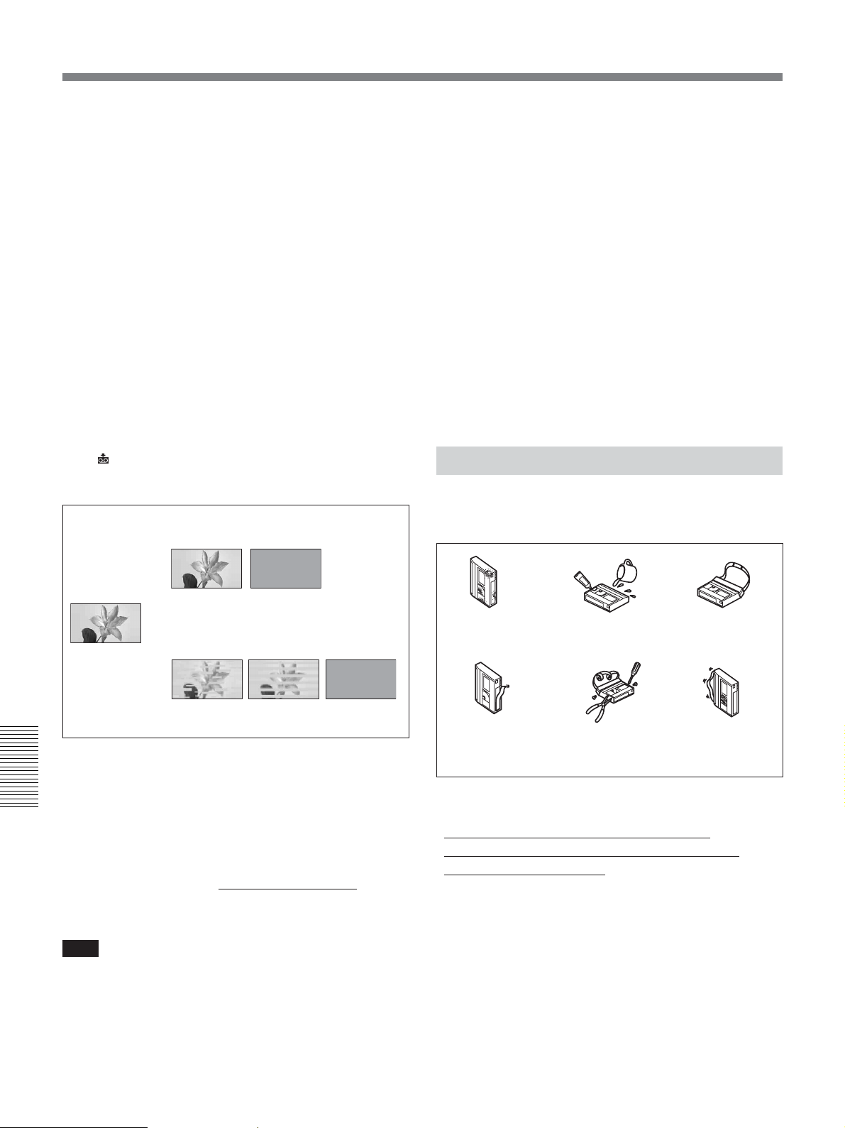
Notes on Use
Every 50 hours
If you repeat the tape transport operation, the video
heads will become dirty and coated with fine dirt or
dust. Clean the heads every 50 hours.
After using a tape prone to clog the heads
After using such a tape causes the symptoms
illustrated below, clean the heads.
When the symptoms caused by clogged video
heads appear
Even if you clean the heads periodically, clogging of
the heads may occur anyway. Clean the heads when:
•mosaic-pattern noise appears on the playback picture.
• the playback picture freezes.
•a part of the playback picture does not move.
• playback pictures do not appear.
• playback audio is interrupted.
•“x
Dirty video head. Use a cleaning cassette.”
appears during recording.
Image when the video head is dirty
With an HDV
–Using a damaged tape.
–Using the unit for a long time.
–Using the unit where there is a lot of dirt, dust, or
sand.
– Leaving a tape in the unit for a long time.
Cleaning cassettes are replaceable. After using the
supplied cleaning cassette for the specified number of
times, buy a cleaning cassette for replacement.
After prolonged use, the video heads may become
worn out. If optimum picture quality is not restored
even after you have cleaned the video heads with the
cleaning cassette, the video heads may have worn out.
In that case, you have to replace the video heads with
new ones. Please consult your Sony dealer.
Notes on the Video Cassettes
Note that using a tape such as those below can damage
the unit.
Normal image
Playback
image pauses
With a DV/DVCAM
Playback image
disappears
To use the cleaning cassette
Clean the video head by playing the cleaning cassette
for ten seconds.
Chapter 6 Maintenance
* If the playback image continues to be stationary or
any of the symptoms on the above remain even after
cleaning with the cleaning cassette, there may be a
problem with the tape.
For details, refer to your cleaning cassette’s instruction
manual.
Note
Avoid using that tape.
Using the unit as below will make the video head dirty.
– Subjecting the unit to temperature change or high
humidity.
tCondensation occurs. See page 91.
Playback image
disappears
A moldy
tape
A tape with
a peeling
label
A dirty
tape
A tape that
has been
dismantled
A spliced
tape
A slack
tape
Using cassettes
•
When using a cassette for the first time we
recommend that you run the tape for about five
seconds before recording.
•When using a cassette that has been stored for a long
time we recommend that you fast-forward and rewind
it for some time. This will correct any winding
irregularity in the cassette.
•Do not repeatedly insert and remove a cassette
without running it. The tape may become slacked or
damaged.
90 Chapter 6 Maintenance
Page 91
Cleaning the terminal
If the gold-plated terminals of a cassette become dirty,
or dirt accumulates on the terminals, the correct
remaining tape time may not be displayed.
Clean the terminal with a swab once every ten times
you eject a cassette.
Terminal
When affixing a label to the cassette
Be sure to affix a label only on the correct location so
as not to cause malfunction of the unit.
Storing cassettes
•After using the tape rewind it, put it in its case and
store vertically. (To prevent picture and sound
distortion.)
•Do not store tapes in the following places:
–Where the temperature gets high (in strong
sunshine, inside a car or near a heater)
–Where there is high humidity
– In a strong magnetic field (near a TV or speakers)
About Moisture Condensation
If the unit or cassette is brought directly from a cold to
a warm location, moisture may condense inside or
outside the unit or tape. If you use the tape or video
heads in this condition, the tape may adhere to the
head drum, and the video heads or the tape may be
damaged, or a malfunction may occur.
When condensation occurs, the alarm messages
“% Z Moisture condensation. Eject the cassette” or
“% Moisture condensation. Turn off for 1H.” appears.
Moisture condensation is likely to occur under the
following conditions:
• The unit or cassette is brought from the cold outdoors
to a warm indoor location.
• The unit or cassette is brought from the airconditioned indoors to the hot outdoors.
• The unit is used in a place subject to cold currents
from an air conditioner.
When bringing the unit or cassette from a cold place to
a warm place or vice versa, put it in a plastic bag and
seal the bag tightly. After bringing it into the new
place, leave the bag on for more than one hour, and
remove the bag when the air temperature inside it has
reached the temperature surrounding it.
Notes on LCD Screen
LCD screen is manufactured using high-precision
technology. The ratio of effective pixels is 99.99% or
more. However, there may be some tiny black points
and/or bright points (red, blue, green or white) that
constantly appear on LCD screen. These points do not
affect the recorded picture in any way.
Do not place the unit with LCD screen pointing toward
the sun. Otherwise, the unit may be damaged.
To clean LCD screen
To remove dirt or to clean fingerprints from LCD
screen, use an LCD cleaning kit (not supplied). When
you use the LCD cleaning kit, do not pour the cleaning
liquid directly on LCD. Always soak the liquid in
cleaning paper and wipe LCD with this paper.
If moisture condensation occurred
Remove the cassette immediately. While the alarm
indicator is displayed, you cannot operate the unit
except to press EJECT button.
Turn off the power until the condensation disappears
(approximately 1 hour). If the alarm message does not
appear when you turn on the unit, and if % or Z does
not blink when you insert a cassette and press the
video operation button, you can use the unit again.
If there is negligible condensation in the unit, this
condensation may not be detected. In that case, the
cassette may not be ejected for approximately 10
seconds. This is not a malfunction.
Chapter 6 Maintenance
Chapter 6 Maintenance 91
Page 92

Digital Hours Meter
Notes on the License
The digital hours meter keeps cumulative counts of the
total operation time, the head drum rotation time, the
tape running time and the number of unthreading
operations. These counts can be displayed on the
menu. Use them as guidelines for scheduling
maintenance.
In general, consult your Sony dealer about necessary
periodic maintenance checks.
The digital hours meter has the following four display
modes and you can check them in [HOURS METER]
of [OTHERS] menu (page 78).
• OPERATION mode
The cumulative total hours of operating time is
displayed in 10-hour increments.
• DRUM RUN mode
The cumulative total hours of drum rotation with tape
threaded is displayed in 10-hour increments.
•TAPE RUN mode
The cumulative total hours of tape running time is
displayed in 10-hour increments.
ANY USE OF THIS PRODUCT OTHER THAN
CONSUMER PERSONAL USE IN ANY MANNER
THAT COMPLIES WITH THE MPEG-2
STANDARD FOR ENCODING VIDEO
INFORMATION FOR PACKAGED MEDIA IS
EXPRESSLY PROHIBITED WITHOUT A LICENSE
UNDER APPLICABLE PATENTS IN THE MPEG-2
PATENT PORTFOLIO, WHICH LICENSE IS
AVAILABLE FROM MPEG LA, L.L.C., 250
STEELE STREET, SUITE 300, DENVER,
COLORADO 80206.
•THREADING mode
The cumulative number of tape unthreading
operations is displayed in 10-operation increments.
About the Built-in Rechargeable Battery
The unit is provided with a rechargeable battery that
retains the date/time and various settings regardless of
Chapter 6 Maintenance
power-on and power-off. The rechargeable battery is
charged as long as the unit is operated. If the period of
operating the unit is short, the battery discharges
gradually and if it is not used at all for approximately 3
months, the battery will discharge completely. If that
case, charge the battery and then start using the unit. If
you do not need to record the date and time when the
rechargeable battery is not fully charged, you can use
the unit in this state.
Charging the rechargeable battery
Connect the unit to an AC output using the power cord
for about 24 hours. (The unit does not need to be
turned on.)
92 Chapter 6 Maintenance
Page 93
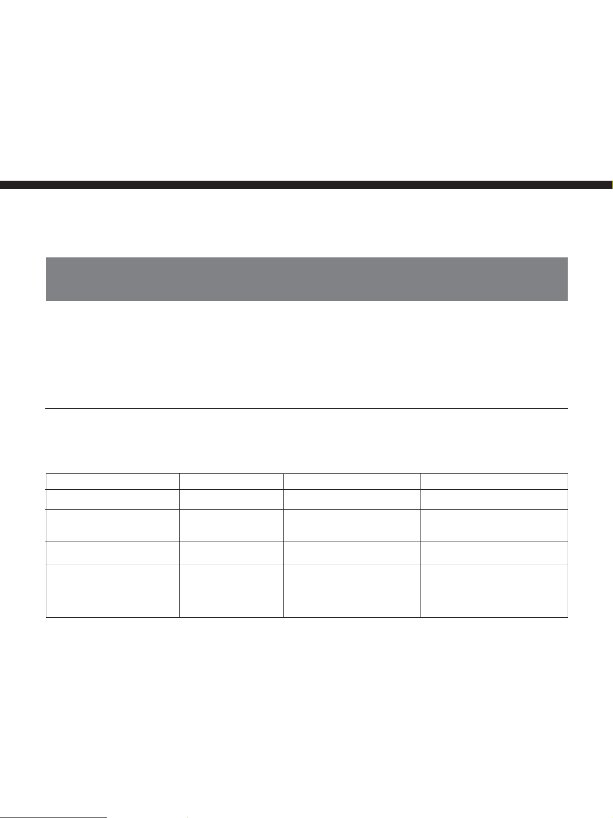
Appendix
Compatibility of HDV, DVCAM, and DV Formats
HDV format is an HD VCR format based on DV format of the globally widespread general consumer digital VCR
system. This format has the newly defined data recording specifications for HD signals compressed by MPEG2. It
applies the same cassette, tape speed, and track pitch as DV format.
The differences, compatibility, and restrictions in editing of HDV1080i, DVCAM, and DV formats are explained
below.
Main differences between HDV1080i, DVCAM, and DV Formats
(The unit and other equipment for professional use may be functionally extended. For details, see the notes below
the table.)
Specification HDV1080i DVCAM DV (SP)
Track pitch
Audio sampling frequency
Audio recording mode
Time code
1)
10 µm
16 bit: 48 kHz
Lock mode
Drop frame mode
(60i only)
No user bits
4)
4)
15 µm
12 bit: 32 kHz
16 bit: 48 kHz
Lock mode
NTSC: SMPTE time code
(DF/NDF, including user bits)
PAL: EBU time code
(including user bits)
10 µm
12 bit: 32 kHz
16 bit: 32 kHz, 44.1 kHz, 48 kHz
Unlock mode
Drop frame mode
(NTSC only)
No user bits
3)
4)
4)
2)
1) There are two modes for audio signals recording: Lock mode and Unlock mode. In Lock mode, the sampling frequencies of
audio and video are synchronized. In Unlock mode, adopted by the consumer DV format, the two sampling frequencies are
independent. Lock mode maintains high compatibility with higher formats and offers better digital processing and smooth
transition than Unlock mode when you edit audio.
2) The unit cannot record in DV format with 16 bit:32 kHz or 44.1 kHz.
3) The unit has been functionally extended with a function for switching between Lock mode and Unlock mode.
4) The unit has been functionally extended with a function to enable selecting DF/NDF and user bits setting for 60i with HDV
or DV (SP) format.
Appendix
Appendix 93
Page 94
Compatibility of HDV, DVCAM, and DV Formats
Playback compatibility
The compatibility between playback tape format and player is summarized in the table below.
Playback
tape format
DV
DVCAM
HDV
Player
DV format model
Playback is possible.
(Some equipment cannot
play a tape recorded in the
LP mode.)
Playback may be possible on
some models.
No playback is possible.
DVCAM format model
Only playback of a tape
recorded in SP mode is
possible. Some equipment can
play a tape recorded in LP
mode.
Playback is possible
No playback is possible.
HDV1080i format model
(The unit)
Only playback of a tape
recorded in SP mode is
possible. Some equipment can
play a tape recorded in LP
mode. (The unit can play back
a DV-formatted tape in SP
mode only.)
Playback is possible
Playback is possible*
* The unit can play back for HDV720/30p format, but you cannot output the video signals from HDV/DV jack.
The unit cannot play back other than HDV1080/60i, HDV1080/50i, such as HDV1080/30F, HDV1080/25F, HDV1080/
24F, HDV720/25p, and HDV720/24p format. The unit cannot input/output, record, or play back extended HDV signals.
On the unit, you cannot input/output 4-channel audio signals, record or playback in HDV extension.
Cassette compatibility
A DV format cassette tape can be used for HDV. The recording bit rate and recording track pitch on a tape of the
HDV1080i system used for HVR-M25U/M25N/M25E/M25P are about 25 Mbps and 10 µm, respectively. The
specifications are the same as that of home use DV (SP) tapes. The recording time on an HDV tape is also the
same as that of DV (SP).
The track pitch of DVCAM is 15 µm, which is 1.5 times of HDV/DV (SP). Therefore, the recording time using
DVCAM recording on a same tape will be two-thirds of the time available when HDV/DV (SP) recording is used.
Appendix
94 Appendix
Page 95
Dubbing with S VIDEO or VIDEO jacks
When you use the unit as a recorder to perform dubbing between the unit and another equipment using S VIDEO
jack and VIDEO jack, the format to be used for recording is set in accordance with [
[IN/OUT REC] menu.
For details, see the following table.
Playback and editing of a tape may be restricted for some dubbing methods. Read Chapter 4 “Dubbing to another
equipment using i.LINK jack, Duplication, Audio Dubbing, and Connecting with a Computer” before dubbing a
tape.
Some editing software can correctly edit even a tape created in [LOCK MODE]. In that case, select [LOCK
MODE] if required.
Recording tapes used when the unit serves as a recorder
Menu item
REC MODE] setting in
Input signal format
NTSC or PAL
—: Setting independent
REC MODE
DVCAM
DV SP
AUDIO LOCK
—
LOCK MODE
UNLOCK MODE
Recording tape format (AUDIO MODE)
DVCAM (LOCK MODE)
DV (LOCK MODE)
DV (UNLOCK MODE)
Appendix 95
Appendix
Page 96
Compatibility of HDV, DVCAM, and DV Formats
Dubbing with HDV/DV jack
When you perform dubbing between the unit and digital video equipment connected with the i.LINK cable using
the unit as a player,
menu setting of the unit.
If you use the unit as a recorder, the format of a tape used for recording is determined in accordance with
DV jack input format and menu setting of the unit. For details, check the following table on page 97.
Playback and editing using this tape may be limited for some dubbing methods. Before dubbing, read Chapter 4
“Dubbing to another equipment using i.LINK jack, Duplication, Audio Dubbing, and Connecting with a
Computer.”
i.LINK output when the unit is used as a player
HDV/DV jack output format is determined in accordance with the playback tape format and
HDV/
Playback tape
format
HDV
DVCAM
DV
Notes
Menu item
HDV/DV SEL
AUTO
HDV
DV
AUTO
HDV
DV
AUTO
HDV
DV
i.LINK SET
HDVtDV CONV i.LINK output format (AUDIO MODE)
OFF
DVCAM
DV (SP)
OFF
DVCAM
DV (SP)
—
—
—
—
—
—
—
HDV (LOCK MODE)
DVCAM (LOCK MODE)
DV (UNLOCK MODE)
HDV (LOCK MODE)
DVCAM (LOCK MODE)
DV (UNLOCK MODE)
No output
DVCAM (Complies with playback tape)
No output
DVCAM (Complies with playback tape)
DV (Complies with playback tape)
No output
DV (Complies with playback tape)
•When you play back a tape employed with a copy-protection signal on the unit, recording is prevented to record
images from the unit to other equipment.
•You cannot up convert DVCAM(DV) format to HDV format on the unit.
•During playback in HDV, if [DV SP] is selected from [HDVtDV CONV] in [i.LINK SET], AUDIO MODE is
fixed to UNLOCK MODE.
•When you play back a tape in DVCAM or DV format, the unit cannot convert between DVCAM and DV format,
or switch between LOCK MODE and UNLOCK MODE.
Appendix
96 Appendix
Page 97
Recording tape when the unit is used as a recorder
i.LINK input format
HDV
DVCAM
DV
Menu item
HDV/DV SEL
AUTO
HDV
DV
AUTO
HDV
DV
AUTO
HDV
DV
REC MODE
—
—
—
DVCAM
DV SP
—
DVCAM
DV SP
DVCAM
DV SP
—
DVCAM
DV SP
1)
Recording tape format (AUDIO MODE)
HDV (LOCK MODE)
HDV (LOCK MODE)
No recording
DVCAM (Complies with input signals)
DV (Complies with input signals)
No recording
DVCAM (Complies with input signals)
DV (Complies with input signals)
2)
DVCAM
DV (Complies with input signals)
No recording
DVCAM
DV (Complies with input signals)
(Complies with input signals)
2)
(Complies with input signals)
3)
1) When the unit is used as a recorder, the recording format is determined by [ REC MODE] setting on [IN/OUT REC]
menu if the input signal format is DVCAM or DV.
2) If you duplicate a tape when the unit is set to DVCAM to be used as a recorder, the time code format of the duplicated tape
will be partially different from the time code format specified as DVCAM (note, however, that this does not affect editing
accuracy in special cases).
3) The unit cannot switch between LOCK MODE and UNLOCK MODE. AUDIO MODE complies with input signals.
Notes
•On the unit, HDV signals input from i.LINK cannot be down converted to DVCAM(DV) for recording.
• If you use the tapes described in 2) above for editing, you may encounter function limitations regardless of the
player and recorder formats.
• Some DV video equipment may playback a DVCAM-formatted tape, however the contents cannot be guaranteed.
Therefore, even if you use a proper DVCAM-formatted tape for playback, the unit may dub and create a
DVCAM-formatted tape. The time code will be partially different from the time code format specified as
DVCAM on other DV video equipment.
•You cannot use the unit to record video and audio recorded with copyright protection signals. If you try to record
such a video or audio, the message “Cannot record due to copyright protection.” appears on LCD monitor.
Pictures output from COMPONENT OUT jacks are switched to either 480i or 576i automatically, regardless of
the menu you have set on the unit.
Limitations on editing
During editing, you will encounter limitations according to the format differences on a tape dubbed or edited using
HDV/DV jack.
For details, refer to Chapter 4 “Dubbing to another equipment using i.LINK jack, Duplication, Audio Dubbing,
and Connecting with a Computer.”
Appendix
Appendix 97
Page 98

About i.LINK
The HDV/DV jack provided on the unit is an
i.LINK-compliant jack. This section describes the
i.LINK standard and its features.
What is i.LINK?
i.LINK is a digital serial interface for sending and
receiving digital video, digital audio, and other data
between the unit and other equipment equipped with
an i.LINK terminal. You can also control other
equipment using i.LINK.
i.LINK-compatible equipment can be connected using
an i.LINK cable. Possible applications are operations
and data exchange with various digital AV equipment.
When two or more i.LINK-compatible equipment are
connected to the unit, operations and data exchange are
possible with equipment directly connected to the unit
and also with equipment connected to the unit via
other equipment.
Note, however, that the method of operation may vary
depending on the characteristics and specifications of
the equipment to be connected. Also, there are cases
where operations and data exchange may not be
possible even if the connection is made.
Notes
•Normally, only one device can be connected to the
unit using i.LINK cable. When you connect the unit
to HDV/DVCAM (DV)-compliant equipment that
allows multiple connections, refer to the operating
instructions of the equipment to be connected.
• i.LINK is an easy-to-remember term for the IEEE
1394 proposed by Sony, and is a trademark approved
by many corporations in Japan and overseas.
• IEEE 1394 is an international standard standardized
by the Institute of Electrical and Electronics
Engineers.
About the i.LINK baud rate
The maximum baud rate of i.LINK varies depending
on the equipment. There are three types.
S100 (Approximately 100 Mbps*)
S200 (Approximately 200 Mbps)
S400 (Approximately 400 Mbps)
The baud rate is listed under “Specifications” in the
operating instructions of individual equipment. It may
Appendix
be indicated near the i.LINK interface on some
equipment.
The baud rate may vary from the indicated value when
the unit is connected to equipment with a different
maximum baud rate.
*What is Mbps?
Mbps stands for “megabits per second,” or the volume of
data that can be sent or received in 1 second. For
example, a baud rate of 100 Mbps means that 100
megabits of data can be sent in 1 second.
To use i.LINK functions of the unit
For details on how to perform dubbing when the unit is
connected to other video equipment that has an i.LINK
jack, see page 44, 54.
The unit can also be connected to other i.LINKcompatible equipment made by Sony (i.e., a VAIO
series computer) as well as video equipment.
The unit may not be able operate with some i.LINK
video equipment such as digital televisions, DVD
recorders/players, and MICROMV recorders/players
even if they are equipped with i.LINK jack. Before
connecting to another equipment, confirm whether this
equipment is HDV/DVCAM (DV) compatible.
For details on precautions on connections and whether
or not software applications compatible with the unit
are available, refer to the operating instructions of the
equipment to be connected.
Notes
•When you connect with the i.LINK cable to a
computer and the unit, check the direction of the jack.
If you forcibly insert the jack, the terminal may be
damaged or cause the unit to malfunction.Align v
mark of the i.LINK cable with V mark on the unit
and insert the i.LINK cable.
•Be sure to connect the i.LINK cable to a computer
first and then connect it to the unit. If you connect the
i.LINK cable to the unit first, it may cause the unit to
malfunction because of static electricity.
•When you connect the unit to equipment equipped
with a 6-pin type i.LINK jack, connect the cable to
the 6-pin type i.LINK jack first.
•When you connect the unit to equipment equipped
with an i.LINK jack using the i.LINK cable, power
off the equipment and remove the power cord from
the AC outlet before connecting (or disconnecting)
the i.LINK cable. If the i.LINK cable is connected (or
disconnected) while the equipment power cord is
connected to the AC outlet, a high-voltage current (8
to 40 V) output from the i.LINK jack of the
equipment flows into the unit and damage it.
About required i.LINK cable
Use a Sony i.LINK cable.
98 Appendix
i.LINK and are trademarks of Sony Corporation.
Page 99
Specifications
System
Video/Audio recording/playing head system
Rotating dual-head helical scan
Audio recording format (HDV)
MPEG-1 Audio Layer2
16-bit 48 kHz (stereo)
Transfer rate 384 kbps
Audio recording format (DVCAM (DV))
12-bit Fs32K (Channel 1/2,
Channel 3/4)
16-bit Fs48K (Channel 1/2)
Video signal 1080/60i, NTSC color,
EIA standard system
1080/50i, PAL color,
CCIR standard system
Usable cassettes Standard DVCAM cassettes with
mark
Mini DVCAM cassettes with
mark
Tape speed (HDV)
Approx. 18.812 mm/s
Tape speed (DVCAM)
Approx. 28.218 mm/s
Tape speed (DV) SP: Approx. 18.812 mm/s
Recording/playback time (HDV)
Approx. 276 min
(using PHDV-276DM)
Approx. 63 min
(using PHDVM-63DM)
Recording/playback time (DVCAM)
Approx. 184 min
(using PHDV-276DM)
Approx. 41 min
(using PHDVM-63DM)
Recording/playback time (DV SP)
Approx. 276 min
(using PHDV-276DM)
Approx. 63 min
(using PHDVM-63DM)
AUDIO jacks
IN Pin jack: –10/–2/+4 dBu
Impedance: Minimum 47 kΩ
(kilo ohms), unbalanced
Maximum input level:
–10: +18 dBu (approx. 6 Vrms)
–2: +24 dBu (approx. 12.5 Vrms)
+4: +30 dBu (approx. 25 Vrms)
OUT Pin jack
Impedance: Maximum 1 kΩ
(kilo ohms)
Output level: 47 kΩ (kilo ohms)
loading, unbalanced
–10 dBu (= full bit –20 dB)
60i system
–10 dBu (= full bit –18 dB)
50i system
PHONES Stereo minijack (ø 3.5),
8 Ω (ohms) loading
VIDEO jacks
IN/OUT BNC type, unbalanced
1.0 Vp-p
(75 Ω (ohms), sync negative)
Sync signal:
0.286 Vp-p (60i/NTSC)
0.3 Vp-p (50i/PAL)
Burst signal:
0.286 Vp-p (60i/NTSC)
0.3 Vp-p (50i/PAL)
S VIDEO jacks
IN/OUT Mini DIN 4-pin, unbalanced
Luminance signal:
1.0 Vp-p
(75 Ω (ohms), sync negative)
Sync signal:
0.286 Vp-p (60i/NTSC)
0.3 Vp-p (50i/PAL)
Chrominance signal:
0.286 Vp-p (60i/NTSC)
(burst, 75 Ω (ohms))
0.3 Vp-p (50i/PAL)
(burst, 75 Ω (ohms))
HDMI OUT jack
Video Type A (19 pin)
480i, 576i, 480p, 576p, 1080i,
720p
Audio 2 channel liner
PCM 48 kHz/16 bits
Appendix
Appendix 99
Page 100

COMPONENT OUT jacks
OUT BNC type
Output at 480i NTSC
With [BETACAM] selected in [IN/OUT REC]
menu
Y: 1.0 Vp-p
(with 0.286 Vp-p sync negative,
output impedance 75 Ω (ohms),
unbalanced)
Pb/Cb/B-Y, Pr/Cr/R-Y: 0.7 Vp-p
(output impedance 75 Ω (ohms),
unbalanced)
(75% color bars with 7.5 IRE
setup)
With [SMPTE] selected in [IN/OUT REC] menu
Y: 1.0 Vp-p
(with 0.3 Vp-p sync negative,
output impedance 75 Ω (ohms),
unbalanced)
Pb/Cb/B-Y, Pr/Cr/R-Y: 0.7 Vp-p
(output impedance 75 Ω (ohms),
unbalanced)
(100% color bars with no setup)
Output with other settings
Y: 1.0 Vp-p
(output impedance 75 Ω (ohms),
unbalanced)
Pb/Cb/B-Y, Pr/Cr/R-Y: 0.7 Vp-p
(output impedance 75 Ω (ohms),
unbalanced)
(100% color bars with no setup)
480i/480p:
Y: with 0.3 Vp-p sync negative
1080i/720p:
Y/Pb/Pr: with 0.6 Vp-p 3-level
sync
General
Peak inrush current
Hot switching inrush current,
measured in accordance with
European standard
EN55103-1: 13.0 A
(230 V)
Power requirements
HVR-M25U
AC120 V, 60 Hz
HVR-M25N
AC100-240 V, 50/60 Hz
HVR-M25E
AC220-240 V, 50 Hz
HVR-M25P
AC100-240 V, 50/60 Hz
Power consumption (during play back)
12 W
Operating temperature
5 ˚C to 40 ˚C (41 ˚F to 104 ˚F)
Storage temperature
–20 ˚C to +60 ˚C
(–4 ˚F to +140 ˚F)
HDV/DV jack
i.LINK (IEEE1394,
4-pin connector S100)
Remote control
LANC Stereo mini-minijack (ø 2.5)
CONTROL S IN Stereo minijack (ø 3.5)
Appendix
LCD screen
Picture 6.8 cm (2.7 type)
Total dot number 211 200 dots
960 (Horizontal) × 220 (Vertical)
100 Appendix
 Loading...