

Sony HVBK-1505 Installation Instructions Manual
4-125-828-02(1)
Analog Input Board
設置説明書
Installation Instructions (For HVR-1500A)
Manuel d’installation
Installationsanleitung (Für HVR-1500A)
Istruzioni per l’installazione
Instrucciones de instalación
お買い上げいただきありがとうございます。
ご使用にあたっては、デジタルHDビデオカセットレコーダー本体に付
•
属の取扱説明書の「安全のために」と「 」、「 」をよくお読
みください。お読みになったあとは、 いつでも見られるところに必ず
保管してください。
本基板の取り付けは、必ずお買い上げ店またはソニーのサービス窓口に
•
ご依頼ください。
HVBK-1505
Sony Corporation © 2008 Printed in Japan
以下の「取り付け」の項は、特約店およびソニーのサービス窓口用の説
明です。
お客様がこの説明書に記載された取り付け作業を行うと、火災や、感電
やけがなどの人身事故につながることがあります。
お客様ご自身では絶対に取り付け作業を行わないでください。
本基板の取り付けは、必ずお買い上げ店またはソニーのサービス窓口に
ご依頼ください。
(
HVR-1500A
用)
(Pour le modèle HVR-1500A)
(Per l’HVR-1500A)
(Para HVR-1500A)
電気製品は、安全のための注意事項を守らないと、
火災や人身事故になることがあります。
お客様へ
この設置説明書には、事故を防ぐための重要な注意事項と製品の取り扱
いかたを示してあります。この設置説明書をよくお読みのうえ、製品を
安全にお使いください。お読みになったあとは、いつでも見られるとこ
ろに必ず保管してください。
Before operating the unit, please read this manual thoroughly and retain
it for future reference.
Avant d’utiliser l’appareil, veuillez lire attentivement ce manuel et le
conserver pour future référence.
Bitte lesen Sie dieses Handbuch vor der Benutzung des Geräts
sorgfältig durch und bewahren Sie es zum späteren Nachschlagen auf.
Leggere attentamente questo manuale prima di utilizzare l’unità, e
conservarlo per riferimenti futuri.
Antes de poner en funcionamiento la unidad, lea detenidamente este
manual y consérvelo para referencias futuras.
For the customers in the USA
This equipment has been tested and found to comply with the limits for
a Class A digital device, pursuant to Part 15 of the FCC Rules. These
limits are designed to provide reasonable protection against harmful
interference when the equipment is operated in a commercial
environment. This equipment generates, uses, and can radiate radio
frequency energy and, if not installed and used in accordance with the
instruction manual, may cause harmful interference to radio
communications. Operation of this equipment in a residential area is
likely to cause harmful interference in which case the user will be
required to correct the interference at his own expense.
You are cautioned that any changes or modifications not expressly
approved in this manual could void your authority to operate this
equipment.
All interface cables used to connect peripherals must be shielded in
order to comply with the limits for a digital device pursuant to Subpart B
of Part 15 of FCC Rules.
This device complies with Part 15 of the FCC Rules. Operation is
subject to the following two conditions: (1) This device may not cause
harmful interference, and (2) this device must accept any interference
received, including interference that may cause undesired operation.
For the customers in Canada
This Class A digital apparatus complies with Canadian ICES-003.
For the customers in Europe
This product with the CE marking complies with the EMC Directive
issued by the Commission of the European Community.
Compliance with this directive implies conformity to the following
European standards:
• EN55103-1: Electromagnetic Interference (Emission)
• EN55103-2: Electromagnetic Susceptibility (Immunity)
This product is intended for use in the following Electromagnetic
Environment(s):
E1 (residential), E2 (commercial and light industrial), E3 (urban
outdoors) and E4 (controlled EMC environment, ex. TV studio).
The manufacturer of this product is Sony Corporation, 1-7-1 Konan,
Minato-ku, Tokyo, 108-0075 Japan.
The Authorized Representative for EMC and product safety is Sony
Deutschland GmbH, Hedelfinger Strasse 61, 70327 Stuttgart, Germany.
Pour les utilisateurs au Canada
Cet appareil numérique de la classe A est conforme à la norme NMB003 du Canada.
Pour les clients en Europe
Ce produit portant la marque CE est conforme à la Directive sur la
compatibilité électromagnétique (EMC) émise par la Commission de la
Communauté européenne.
La conformité à cette directive implique la conformité aux normes
européennes suivantes:
• EN55103-1: Interférences électromagnétiques (émission)
• EN55103-2: Sensibilité électromagnétique (immunité)
Ce produit est prévu pour être utilisé dans les environnements
électromagnétiques suivants:
E1 (résidentiel), E2 (commercial et industrie légère), E3 (urbain
extérieur) et E4 (environnement EMC contrôlé ex. studio de télévision).
Le fabricant de ce produit est Sony Corporation, 1-7-1 Konan, Minatoku, Tokyo, 108-0075 Japon.
Le représentant autorisé pour EMC et la sécurité des produits est Sony
Deutschland GmbH, Hedelfinger Strasse 61, 70327 Stuttgart,
Allemagne.
Für Kunden in Europa
Dieses Produkt besitzt die CE-Kennzeichnung und erfüllt die
EMV-Richtlinie der EG-Kommission.
Angewandte Normen:
• EN55103-1: Elektromagnetische Verträglichkeit
(Störaussendung)
• EN55103-2: Elektromagnetische Verträglichkeit
(Störfestigkeit),
für die folgenden elektromagnetischen Umgebungen:
E1 (Wohnbereich), E2 (kommerzieller und in beschränktem Maße
industrieller Bereich), E3 (Stadtbereich im Freien) und E4 (kontrollierter
EMV-Bereich, z.B. Fernsehstudio).
Der Hersteller dieses Produkts ist Sony Corporation, 1-7-1 Konan,
Minato-ku, Tokyo, 108-0075 Japan.
Der autorisierte Repräsentant für EMV und Produktsicherheit ist Sony
Deutschland GmbH, Hedelfinger Strasse 61, 70327 Stuttgart,
Deutschland.
Per i clienti in Europa
Questo prodotto recante il marchio CE è conforme alla direttiva sulla
compatibilità elettromagnetica (EMC) emessa dalla Commissione della
Comunità Europea.
La conformità a questa direttiva implica la conformità alle seguenti
normative europee:
• EN55103-1: Interferenza elettromagnetica (Emissione)
• EN55103-2: Sensibilità ai disturbi elettromagnetici (Immunità)
Questo prodotto è destinato all’uso nei seguenti ambienti
elettromagnetici:
E1 (residenziali), E2 (commerciali e industriali leggeri), E3 (esterni
urbani) e E4 (ambienti EMC controllati, ad esempio studi televisivi).
Il fabbricante di questo prodotto è la Sony Corporation, 1-7-1 Konan,
Minato-ku, Tokyo, 108-0075 Giappone.
La rappresentanza autorizzata per EMC e la sicurezza dei prodotti è la
Sony Deutschland GmbH, Hedelfinger Strasse 61, 70327 Stoccarda,
Germania.
Para los clientes de Europa
Este producto cumple con las directivas de compatibilidad
electromagnética de la Comisión Europea.
El cumplimiento de estas directivas implica la conformidad con los
siguientes estándares europeos:
• EN55103-1: Interferencia electromagnética (Emisión)
• EN55103-2: Susceptibilidad electromagnética (Inmunidad)
Este producto está ha sido diseñado para utilizarse en los entornos
electromagnéticos siguientes: E1 (zona residencial), E2 (zona
comercial e industrial ligera), E3 (exteriores urbanos), y E4 (entorno
con EMC controlada, p. ej., estudio de televisión).
El fabricante de este producto es Sony Corporation, con dirección en 17-1 Konan, Minato-ku, Tokio, 108-0075 Japón.
El Representante autorizado para EMC y seguridad del producto es
Sony Deutschland GmbH, Hedelfinger Strasse 61, 70327 Stuttgart,
Alemania.
お使いになる前に、必ず動作確認を行ってください。故障その他に伴
う営業上の機会損失等は保証期間中および保証期間経過後にかかわ
らず、補償はいたしかねますのでご了承ください。
Note
Always verify that the unit is operating properly before use.
SONY WILL NOT BE LIABLE FOR DAMAGES OF
ANY KIND INCLUDING, BUT NOT LIMITED TO,
COMPENSATION OR REIMBURSEMENT ON
ACCOUNT OF THE LOSS OF PRESENT OR
PROSPECTIVE PROFITS DUE TO FAILURE OF THIS
UNIT, EITHER DURING THE WARRANTY PERIOD OR
AFTER EXPIRATION OF THE WARRANTY, OR FOR
ANY OTHER REASON WHATSOEVER.
Remarque
Vérifiez toujours que l’appareil fonctionne correctement
avant l’utilisation. Sony n’assumera pas de responsabilité
pour les dommages de quelque sorte qu’ils soient,
incluant mais ne se limitant pas à la compensation ou au
remboursement, à cause de la perte de profits actuels ou
futurs suite à la défaillance de cet appareil, que ce soit
pendant la période de garantie ou après son expiration,
ou pour toute autre raison quelle qu’elle soit.
Hinweis
Bestätigen Sie vor dem Gebrauch immer, dass das Gerät
richtig arbeitet. SONY KANN KEINE HAFTUNG FÜR
SCHÄDEN JEDER ART, EINSCHLIESSLICH ABER
NICHT BEGRENZT AUF KOMPENSATION ODER
ERSTATTUNG, AUFGRUND VON VERLUST VON
AKTUELLEN ODER ERWARTETEN PROFITEN
DURCH FEHLFUNKTION DIESES GERÄTS ODER AUS
JEGLICHEM ANDEREN GRUND, ENTWEDER
WÄHREND DER GARANTIEFRIST ODER NACH
ABLAUF DER GARANTIEFRIST, ÜBERNEHMEN.
Nota
Verificare sempre che l’apparecchio stia funzionando
correttamente prima di usarlo. LA SONY NON SARÀ
RESPONSABILE DI DANNI DI QUALSIASI TIPO,
COMPRESI, MA SENZA LIMITAZIONE A,
RISARCIMENTI O RIMBORSI A CAUSA DELLA
PERDITA DI PROFITTI ATTUALI O PREVISTI
DOVUTA A GUASTI DI QUESTO APPARECCHIO, SIA
DURANTE IL PERIODO DI VALIDITÀ DELLA
GARANZIA SIA DOPO LA SCADENZA DELLA
GARANZIA, O PER QUALUNQUE ALTRA RAGIONE.
Nota
Verifique siempre que esta unidad funciona correctamente
antes de utilizarlo. SONY NO SE HACE RESPONSIBLE
POR DAÑOS DE NINGÚN TIPO, INCLUYENDO PERO
NO LIMITADO A LA COMPENSACIÓN O PAGO POR
LA PÉRDIDA DE GANANCIAS PRESENTES O
FUTURAS DEBIDO AL FALLO DE ESTA UNIDAD, YA
SEA DURANTE LA VIGENCIA DE LA GARANTÍA O
DESPUÉS DEL VENCIMIENTO DE LA GARANTÍA NI
POR CUALQUIER OTRA RAZÓN.
概要/Overview/Aperçu/
Kurzbeschreibung/
Descrizione/Vista general
アナログインプットボード HVBK-1505はデジタルHDビデオカセットレ
コーダー HVR-1500Aのオプション基板です。
オプション 基板HVBK-1505には、取り付け 用 ネジ 1 本(M3×6)が付属
しています。
HVR-1500Aに本基板を取り付けた後の接続や操作については、
HVR-1500Aの取扱説明書をご覧ください。
The HVBK-1505 Analog Input Board is an optional board for
the HVR-1500A HD Digital Videocassette Recorder.
The HVBK-1505 optional board is provided with a fastening
screw (M3 × 6).
Refer to the HVR-1500A Operating Instructions for
information on connecting and operating the HVR-1500A
fitted with the HVBK-1505.
La carte d’entrée analogique HVBK-1505 est une carte
optionnelle prévue pour le magnétoscope enregistreur
numérique HD HVR-1500A.
La carte optionnelle HVBK-1505 est dotée d’une vis de
fixation (M3 × 6).
Voir le mode d’emploi du HVR-1500A pour les informations
sur le raccordement et le fonctionnement du HVR-1500A
équipé de la carte HVBK-1505.
Die Analog-Eingangskarte HVBK-1505 ist eine Option für den
HD-Digitalvideorecorder HVR-1500A.
Die optionale Karte HVBK-1505 verfügt über eine
Befestigungsschraube (M3 × 6).
Näheres über Anschluss und Betrieb des HVR-1500A mit
installierter HVBK-1505 finden Sie in der
Bedienungsanleitung des HVR-1500A.
La scheda di ingresso analogico HVBK-1505 è una scheda
opzionale per il videoregistratore digitale ad alta definizione
HVR-1500A.
La scheda opzionale HVBK-1505 viene fornita con viti di
fissaggio (M3 × 6).
Per ulteriori informazioni sul collegamento e sul
funzionamento del HVR-1500A con montata la scheda HVBK1505, consultare il manuale di istruzioni per l’uso del HVR1500A.
La tarjeta de entrada analógica HVBK-1505 es una tarjeta
opcional para la grabadora de videocasetes digital de alta
definición HVR-1500A.
La tarjeta opcional HVBK-1505 viene con un tornillo de
fijación (M3 × 6).
Consulte el manual de instrucciones de la HVR-1500A para
información sobre la conexión y funcionamiento de la HVR1500A que tenga la HVBK-1505 instalada.
1
b
a
2
cd
3
e
4
5
f
g
i
cd
h
i
6
k
取り付け/Installation/
Installation/Installation/
Installazione/Instalación
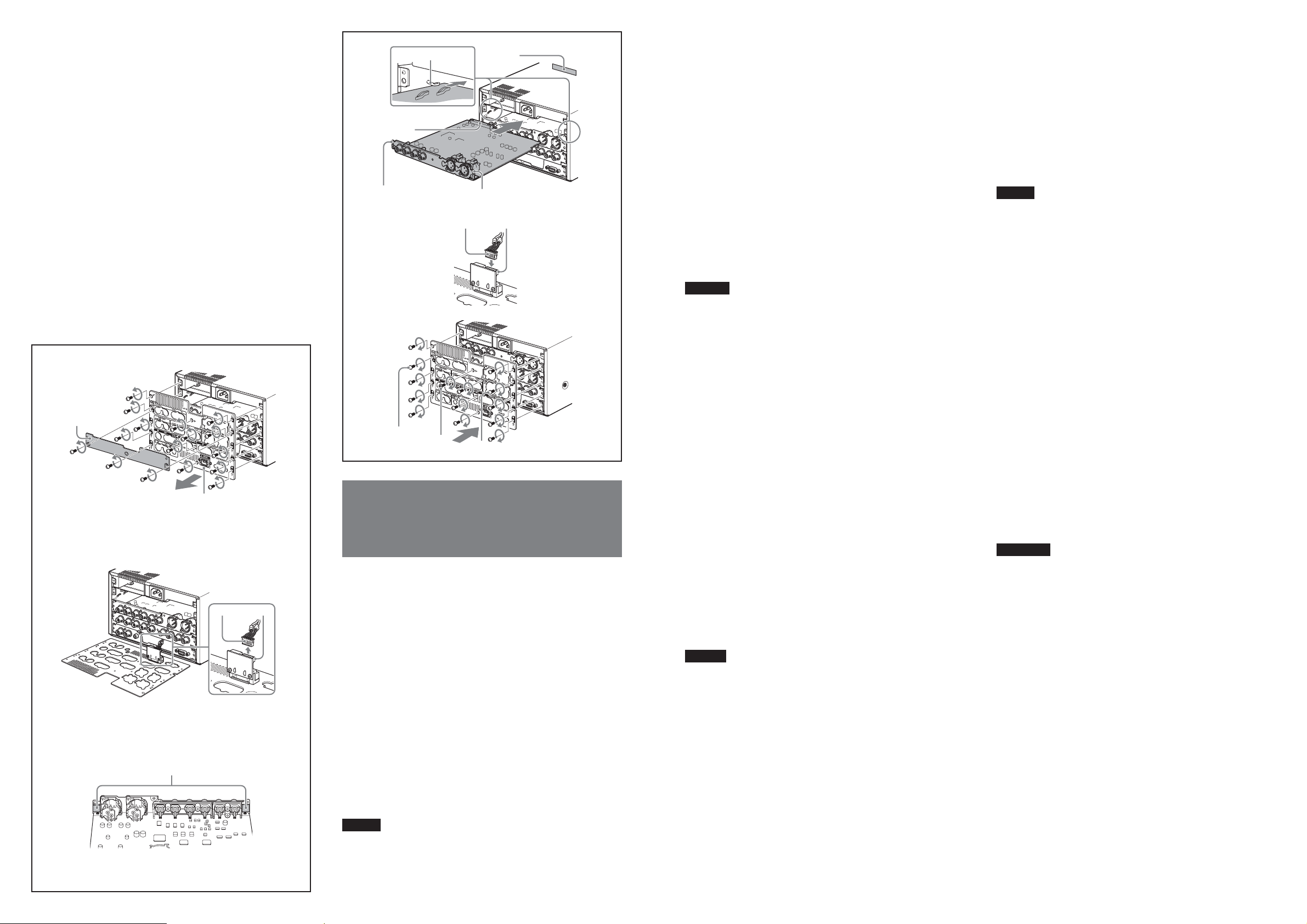
1 ブランクパネル( b)とリア パ ネ ル( a )を は ず す 。
2 コネクターケーブ ル(c)を、リアパネル の i.LINKコネクター
(CN1968A基板CN2)(d)から取りはず す。
3 HVBK-1505基板のブラケットに つ い て いるイーバリアー(e)をはが
し取る。
4 ガイド(f)に合わせてHVBK-1505基板のコネクター(g)を本体の
コネクター(h)にしっかりとはめ込む。
このとき、位置決め穴(i)を本体端部のダボに合わせるようにす
る。
5 リアパネルのi.LINKコネクター(CN1968A 基板CN2)(d)に、手
順2 で外したコネクターケーブル(c)を 接 続 す る 。
6 リアパネルを元に戻す。このとき、付属の取り付け用ネジ(j)も締
める。
ブランクパネルを固定していたネジ(k)を利用し、HVBK-1505基板
を本体に固定する(2か所)。
Caution
If this option is installed incorrectly, personal injury or damage
to peripheral items may occur due to fire, shock, or other
accidental circumstances. To avoid such risks, installation
should be performed by qualified service personnel.
j
k
1 Remove the blanking panel (b) and the rear panel (a).
2 Disconnect the connector cable (c) from the i.LINK
connector (CN1968A board CN2) (d) of the rear panel.
3 Remove the electromagnetic shieldings (e) attached to the
bracket of the HVBK-1505 board.
4 Insert the HVBK-1505 board, aligning it with the guides
(f), and plug the connector (g) on the HVBK-1505 board
into the connector (h) on the HVR-1500A unit.
At this point, align the positioning holes (i) with the studs
at the edge of the unit.
5 Connect the connector cable (c) disconnected in step 2 to
the i.LINK connector (CN1968A board CN2) (d) of the
rear panel.
6 Replace the rear panel. Fasten the supplied screw (j).
Using the screws (k) that secured the blanking panel,
secure the HVBK-1505 board (2 locations).
Attention
L’installation incorrecte de cette option pourra donner lieu à
des blessures personnelles ou bien des dommages à des
éléments périphériques suite à un feu, une décharge électrique
ou d’autres circonstances accidentelles. Pour éviter de tels
risques, faites faire l’installation par un personnel de service
qualifié.
1 Retirez la plaque de suppression (b) et le panneau arrière
(a).
2 Débranchez le câble du connecteur (c) du connecteur
i.LINK (carte CN1968A CN2) (d) sur le panneau arrière.
3 Retirez les blindages électromagnétiques (e) fixés à la
plaque de la carte HVBK-1505.
4 Insérez la carte HVBK-1505 en l’alignant avec les guides
(f) puis branchez le connecteur (g) de la carte HVBK-1505
dans ceux du connecteur (h) du HVR-1500A.
Alignez alors les trous de positionnement (i) avec les
goujons à l’extrémité de l’appareil.
5 Branchez le câble du connecteur (c) déconnecté à l’étape 2
du connecteur i.LINK (carte CN1968A CN2) (d) sur le
panneau arrière.
6 Remettez le panneau arrière en place. Serrez les vis
fournies (j).
À l’aide des vis (k) qui fixent la plaque de suppression,
fixez la carte HVBK-1505 (2 emplacements).
Vorsicht
Bei falscher Installation dieser Option besteht die Gefahr von
Verletzungen bzw. Beschädigung von Peripheriekomponenten
durch Brand, Stromschlag oder sonstige Probleme. Überlassen
Sie daher Installationsarbeiten ausschließlich qualifiziertem
Fachpersonal.
1 Nehmen Sie das Abdeckblech (b) und die Rückseite (a) ab.
2 Trennen Sie das Verbindungskabel (c) vom i.LINK-
Anschluss (Karte CN1968A CN2) (d) auf der Rückseite.
3 Entfernen Sie die elektromagnetischen Abschirmungen (e),
die an den Klammern der Karte HVBK-1505 befestigt
sind.
4 Schieben Sie die Karte HVBK-1505 in die Führungen (f)
und führen Sie sie in den Videorecorder ein. Verbinden Sie
den Steckverbinder (g) der Karte HVBK-1505 mit dem
Steckverbinder (h) am HVR-1500A.
Fluchten Sie nun die Positionieröffnungen (i) mit den
Gewindestutzen am Rand des Geräts.
5 Verbinden Sie das in Schritt 2 abgetrennte
Verbindungskabel (c) mit dem i.LINK-Anschluss (Karte
CN1968A CN2) (d) auf der Rückseite.
6 Bringen Sie die Rückseite an und ziehen Sie die
mitgelieferte Schraube (j) an.
Verwenden Sie die Schrauben (k), mit denen zuvor das
Abdeckblech befestigt war, zur Befestigung der Karte
HVBK-1505 (2 Verwendungsstellen).
Cautela
Se questa opzione non viene installata correttamente, si
possono verificare lesioni alle persone o danni a unità
periferiche dovuti a incendi, scosse elettriche e altri incidenti.
Per evitare tali rischi, l’installazione dovrebbe essere eseguita
da personale tecnico qualificato.
1 Rimuovere il pannello di chiusura (b) e il pannello
posteriore (a).
2 Scollegare il cavo del connettore (c) dal connettore i.LINK
(scheda CN1968A CN2) (d) del pannello posteriore.
3 Rimuovere le protezioni elettromagnetiche (e) collegate
alla staffa della scheda HVBK-1505.
4 Inserire la scheda HVBK-1505, allinearla con le guide (f)
quindi collegare il connettore (g) della scheda HVBK1505 nel connettore (h) dell’unità HVR-1500A.
A questo punto allineare i fori di posizionamento (i) con i
perni che si trovano sul bordo dell’unità.
5 Collegare il cavo del connettore (c) che era stato
scollegato nel punto 2 al connettore i.LINK (scheda
CN1968A CN2) (d) del pannello posteriore.
6 Rimettere a posto il pannello posteriore. Stringere le viti
fornite in dotazione (j).
Utilizzando le viti (k) di fissaggio del pannello di chiusura,
fissare la scheda HVBK-1505 (2 punti).
Precaución
Si esta opción está mal instalada, puede provocar heridas o
daños a los ítems periféricos debido a fuego, descarga eléctrica
u otros accidentes. Para evitar estos riesgos, solicite la
instalación al personal de servicio cualificado.
1 Retire el panel de cierre (b) y el panel trasero (a).
2 Desconecte el cable de conexión (c) del conector i.LINK
(tarjeta CN1968A CN2) (d) situado en el panel trasero.
3 Extraiga los blindajes electromagnéticos (e) acoplados a la
ménsula de la tarjeta HVBK-1505.
4 Inserte la tarjeta HVBK-1505 de modo que quede alineada
con las guías (f), y conecte el conector (g) de la tarjeta
HVBK-1505 en el conector (h) de la unidad HVR-1500A.
En este punto, alinee los orificios de posicionamiento (i)
con los espárragos en el borde de la unidad.
5 Conecte el cable de conexión (c), que se ha desconectado
en el paso 2, en el conector i.LINK (tarjeta CN1968A
CN2) (d) del panel trasero.
6 Vuelva a colocar el panel posterior. Apriete el tornillo
suministrado (j).
Utilizando los tornillos (k) que aseguraban el panel de
cierre, asegure la tarjeta HVBK-1505 (2 ubicaciones).
 Loading...