

Sony HT-V600DP User Manual

DVD/VCR Receiver
Home Theater System
©2003 Sony Corporation
HT-V600DP
4-251-501-11(2)
Operating Instructions
2
Safety Precautions
This lightning flash with arrowhead symbol within an
equilateral triangle is intended to alert the user to
the presence of uninsulated dangerous voltage
within the product’s enclosure that may be of
sufficient magnitude to constitute a risk of electric
shock to persons.
The exclamation point within an equilateral triangle
is intended to alert the user to the presence of
important operating and maintenance (servicing)
instructions in the literature accompanying the
product.
WARNING: Do not install this equipment in a confined space
such as a bookcase or similar unit.
NOTE TO CABLE/TV INSTALLER: This reminder is provided to
call the cable TV system installer’s attention to Article 820-40 of
the National Electric Code (U.S.A.). The code provides guidelines
for proper grounding and, in particular, specifies that the cable
ground shall be connected to the grounding system of the
building, as close to the point of the cable entry as practical.
CAUTION:
The use of optical instruments with
this product will increase eye hazard.
As the laser beam used in this
DVD/VCR Receiver is harmful to eye,
do not attempt to disassemble the
cabinet. Refer servicing to qualified
personal only.
This label is located on the rear panel
of your receiver.
CAUTION:
This DVD/VCR Receiver employs a Laser System.
To ensure proper use of this product, please read this owner’s
manual carefully and retain for future reference. Should the
unit require maintenance, contact an authorized service
location.
Use of controls, adjustments, or the performance of procedures other than those specified herein may result in hazardous radiation exposure.
To prevent direct exposure to laser beam, do not try to open
the enclosure. Visible laser radiation when open. DO NOT
STARE INTO BEAM.
CAUTION: The apparatus should not be exposed to water
(dripping or splashing) and no objects filled with liquids, such
as vases, should be placed on the apparatus.
FCC WARNING: This equipment may generate or use radio
frequency energy. Changes or modifications to this
equipment may cause harmful interference unless the modifications are expressly approved in the instruction manual. The
user could lose the authority to operate this equipment if an
unauthorized change or modification is made.
REGULATORY INFORMATION: FCC Part 15
This product has been tested and found to comply with the
limits for a Class B digital device, pursuant to Part 15 of the
FCC Rules. These limits are designed to provide reasonable
protection against harmful interference when the product is
operated in a residential installation. This product generates,
uses, and can radiate radio frequency energy and, if not
installed and used in accordance with the instruction manual,
may cause harmful interference to radio communications.
However, there is no guarantee that interference will not occur
in a particular installation. If this product does cause harmful
interference to radio or television reception, which can be
determined by turning the product off and on, the user is
encouraged to try to correct the interference by one or more
of the following measures:
Reorient or relocate the receiving antenna.
Increase the separation between the product and
receiver.
Connect the product into an outlet on a circuit different
from that to which the receiver is connected.
Consult the dealer or an experienced radio/TV technician
for help.
Copyrights
This product incorporates copyright protection technology that
is protected by U.S. patents and other intellectual property
rights. Use of this copyright protection technology must be
authorized by Macrovision, and is intended for home and other
limited viewing uses only unless otherwise authorized by
Macrovision.Reverse engineering or disassembly is prohibited.
SERIAL NUMBER: The serial number is found on the back of
this unit. This number is unique to this unit and not available to
others. You should record requested information here and
retain this guide as a permanent record of your purchase.
Model No. ___________________________________
Serial No. ___________________________________
CAUTION: TO PREVENT ELECTRIC SHOCK, MATCH
WIDE BLADE OF PLUG TO WIDE SLOT, FULLY INSERT.
ATTENTION: POUR ÉVITER LES CHOC ÉLECTRIQUES,
INTRODUIRE LA LAME LA PLUS LARGE DE LA FICHE
DANS LA BORNE CORRESPONDANTE DE LA PRISE ET
POUSSER JUSQU’AU FOND.
WARNING: TO REDUCE THE RISK OF FIRE OR ELECTRIC SHOCK, DO NOT EXPOSE THIS APPARATUS TO
RAIN OR MOISTURE.
CAUTION
RISK OF ELECTRIC SHOCK
DO NOT OPEN
CAUTION: TO REDUCE THE RISK
OF ELECTRIC SHOCK
DO NOT REMOVE COVER (OR BACK)
NO USER-SERVICEABLE PARTS INSIDE
REFER SERVICING TO QUALIFIED SERVICE
PERSONNEL.

INTRODUCTION
3
IMPORTANT SAFETY INSTRUCTIONS
1. Read these instructions. - All these safety and oper-
ating instructions should be read before the product is
operated.
2. Keep these instructions. - The safety, operating and
use instructions should be retained for future reference.
3. Heed all warnings. - All warnings on the product and
in the operating instructions should be adhered to.
4. Follow all instructions. - All operating and use
instructions should be followed.
5. Do not use this product near water. – For example:
near a bath tub, wash bowl, kitchen sink, laundry tub,
in a wet basement; or near a swimming pool; and
other areas located near water.
6. Clean only with dry cloth. – Unplug this product from
the wall outlet before cleaning. Do not use liquid
cleaners.
7.
Do not block any ventilation openings. Install in
accordance with the manufacturer’s instructions. -
Slots and openings in the cabinet are provided for
ventilation and to ensure reliable operation of the
product and to protect it from over-heating. The openings should never be blocked by placing the product
on a bed, sofa, rug or other similar surface. This product should not be placed in a built-in installation such
as a bookcase or rack unless proper ventilation is provided or the manufacturer’s instructions have been
adhered to.
8. Do not install near any heat sources such as radiators, heat registers, stoves, or other apparatus
(including amplifiers) that produce heat.
9.
Do not defeat the safety purpose of the polarized
or grounding-type plug. A polarized plug has two
blades with one wider than the other. A grounding
type plug has two blades and a third grounding prong. The wide blade or the third prong are
provided for your safety. If the provided plug does
not fit into your outlet, consult an electrician for
replacement of the obsolete outlet.
10. Protect the power cord from being walked on or
pinched particularly at plugs, convenience
receptacles, and the point where they exit from
the product.
11. Only use attachments/accessories specified by
the manufacturer.
12. Use only with the cart, stand, tripod, bracket, or
table specified by the manufacturer, or sold with
apparatus. When a cart is used, use caution
when moving the cart/product combination to
avoid injury from tip-over.
13. Unplug this product during lightning storms or
when unused for long periods of time.
14.
Refer all servicing to qualified service personnel.
Servicing is required when the product has been
damaged in any way, such as power-supply cord
or plug is damaged, liquid has been spilled or
objects have fallen into the product, the product
has been exposed to rain or moisture, does not
operate normally, or has been dropped.
CAUTION:
PLEASE READ AND OBSERVE ALL WARNINGS AND INSTRUCTIONS IN THIS OWNER’S MANUAL.
AND THOSE MARKED ON THE PRODUCT. RETAIN THIS BOOKLET FOR FUTURE REFERENCE.
This product has been designed and manufactured to assure personal safety. Improper use can result in electric
shock or fire hazard. The safeguards incorporated in this product will protect you if you observe the following procedures for installation, use, and servicing.
This product does not contain any parts that can be repaired by the user.
DO NOT REMOVE THE CABINET COVER, OR YOU MAY BE EXPOSED TO DANGEROUS VOLTAGE. REFER
SERVICING TO QUALIFIED SERVICE PERSONNEL ONLY.

4
Table of Contents
Introduction
Safety Precautions . . . . . . . . . . . . . . . . . . . . . . . . . 2
IMPORTANT SAFETY INSTRUCTIONS . . . . . . . . . . 3
Table of Contents . . . . . . . . . . . . . . . . . . . . . . . . . . 4
Before Use . . . . . . . . . . . . . . . . . . . . . . . . . . . . . . 5-6
Playable Discs . . . . . . . . . . . . . . . . . . . . . . . . . . . 5
Precautions . . . . . . . . . . . . . . . . . . . . . . . . . . . . . 6
Notes on Discs . . . . . . . . . . . . . . . . . . . . . . . . . . 6
About Symbols . . . . . . . . . . . . . . . . . . . . . . . . . . 6
Front Panel . . . . . . . . . . . . . . . . . . . . . . . . . . . . . . . 7
Display Window. . . . . . . . . . . . . . . . . . . . . . . . . . . . 8
Remote Control . . . . . . . . . . . . . . . . . . . . . . . . . . . . 9
Rear Panel . . . . . . . . . . . . . . . . . . . . . . . . . . . . . . . 10
Preparation
Connections . . . . . . . . . . . . . . . . . . . . . . . . . . . 11-14
Connecting Antenna/Cable TV to
DVD/VCR Receiver . . . . . . . . . . . . . . . . . . . . . . 11
Basic TV Connections . . . . . . . . . . . . . . . . . . . . 12
Optional TV Connections . . . . . . . . . . . . . . . . . . 12
Speaker System Connections . . . . . . . . . . . . . . 13
Speaker Positioning . . . . . . . . . . . . . . . . . . . . . . 13
Radio Antenna Connections. . . . . . . . . . . . . . . . 14
Accessory Audio/Video (A/V) Connections to
DVD/VCR Receiver . . . . . . . . . . . . . . . . . . . . . . 14
Digital Device Connections. . . . . . . . . . . . . . . . . 14
Selecting the Output/Input Source . . . . . . . . . . . . 15
Before Operation - Sound Mode Descriptions . . . 16
Mini Glossary for Audio Stream
& Surround Mode. . . . . . . . . . . . . . . . . . . . . . . . 16
Sound Mode . . . . . . . . . . . . . . . . . . . . . . . . . . . 16
VIDEO Operation Setup . . . . . . . . . . . . . . . . . . 17-19
On-Screen Display(OSD) . . . . . . . . . . . . . . . . . . 17
On-Screen Menus Setup . . . . . . . . . . . . . . . . . . 17
Using the VIDEO Setup Menu . . . . . . . . . . . . . . 18
Channel Selection . . . . . . . . . . . . . . . . . . . . . . . 18
Setting the Clock . . . . . . . . . . . . . . . . . . . . . . . . 19
DVD Operation Setup . . . . . . . . . . . . . . . . . . . . 20-23
General Explanation. . . . . . . . . . . . . . . . . . . . . . 20
On-Screen Display. . . . . . . . . . . . . . . . . . . . . . . 20
Initial Settings . . . . . . . . . . . . . . . . . . . . . . . . 21-23
General Operation . . . . . . . . . . . . . . . . . . . . 21
Language . . . . . . . . . . . . . . . . . . . . . . . . . . 21
Picture . . . . . . . . . . . . . . . . . . . . . . . . . . . . . 21
Progressive Scan. . . . . . . . . . . . . . . . . . . . . 21
Speaker Setup. . . . . . . . . . . . . . . . . . . . . . . 22
Others(DRC/PBC) . . . . . . . . . . . . . . . . . . . . 22
Parental Control. . . . . . . . . . . . . . . . . . . . . . 23
Operation
VIDEO Operation . . . . . . . . . . . . . . . . . . . . . . . 24-29
Playback . . . . . . . . . . . . . . . . . . . . . . . . . . . . . . 24
Special Effect Playbacks . . . . . . . . . . . . . . . . . . 24
Search. . . . . . . . . . . . . . . . . . . . . . . . . . . . . 24
Still Picture and Frame-by-Frame Playback . 24
Slow Motion. . . . . . . . . . . . . . . . . . . . . . . . . 24
CM SKIP (Commercial Skip) . . . . . . . . . . . . 24
Normal Recording . . . . . . . . . . . . . . . . . . . . . . . 25
Timer Recording . . . . . . . . . . . . . . . . . . . . . . 25-26
Instant Timer Recording (ITR) . . . . . . . . . . . . . . 27
Dubbing and Editing. . . . . . . . . . . . . . . . . . . . . . 27
Copying from DVD to VIDEO . . . . . . . . . . . . . . . 27
VHS Hi-Fi Stereo System/MTS Broadcast . . . . . 28
Tape Counter Memory Feature. . . . . . . . . . . . . . 29
Additional Information . . . . . . . . . . . . . . . . . . . . 29
DVD and Video CD Operation . . . . . . . . . . . . . 30-32
Playing a DVD and Video CD. . . . . . . . . . . . . . . 30
General Features . . . . . . . . . . . . . . . . . . . . . 30-32
Resuming Playback . . . . . . . . . . . . . . . . . . . 30
Selecting Another TITLE . . . . . . . . . . . . . . . 30
Selecting Another CHAPTER/TRACK. . . . . . 30
Search. . . . . . . . . . . . . . . . . . . . . . . . . . . . . 30
Still Picture . . . . . . . . . . . . . . . . . . . . . . . . . 30
Slow Motion. . . . . . . . . . . . . . . . . . . . . . . . . 31
Shuffle . . . . . . . . . . . . . . . . . . . . . . . . . . . . . 31
Repeat. . . . . . . . . . . . . . . . . . . . . . . . . . . . . 31
Repeat A-B . . . . . . . . . . . . . . . . . . . . . . . . . 31
Time Search . . . . . . . . . . . . . . . . . . . . . . . . 31
3D Surround . . . . . . . . . . . . . . . . . . . . . . . . 31
Changing Video Mode . . . . . . . . . . . . . . . . . 32
Special DVD Features . . . . . . . . . . . . . . . . . . . . 32
Checking the contents of
DVD Video discs: Menus . . . . . . . . . . . . . . . 32
Title Menu . . . . . . . . . . . . . . . . . . . . . . . . . . 32
DVD Menu. . . . . . . . . . . . . . . . . . . . . . . . . . 32
Camera Angle . . . . . . . . . . . . . . . . . . . . . . . 32
Changing the Audio Language . . . . . . . . . . . 32
Changing the Audio Channel . . . . . . . . . . . . 32
Subtitle . . . . . . . . . . . . . . . . . . . . . . . . . . . . 32
Screen Saver. . . . . . . . . . . . . . . . . . . . . . . . 32
Audio CD and MP3 Disc Operation . . . . . . . . . 33-34
Playing an Audio CD and MP3 Disc . . . . . . . . . . 33
Notes on MP3 Files . . . . . . . . . . . . . . . . . . . . . . 33
Pause . . . . . . . . . . . . . . . . . . . . . . . . . . . . . 34
Selecting Another Track. . . . . . . . . . . . . . . . 34
Search. . . . . . . . . . . . . . . . . . . . . . . . . . . . . 34
Shuffle. . . . . . . . . . . . . . . . . . . . . . . . . . . . . 34
Repeat . . . . . . . . . . . . . . . . . . . . . . . . . . . . 34
Repeat A-B . . . . . . . . . . . . . . . . . . . . . . . . . 34
3D Surround . . . . . . . . . . . . . . . . . . . . . . . . 34
Changing the Audio Channel . . . . . . . . . . . . 34
JPEG File Operation . . . . . . . . . . . . . . . . . . . . . . . 35
Viewing JPEG Files on a Disc . . . . . . . . . . . . . . 35
Selecting another Files . . . . . . . . . . . . . . . . 35
Still Picture . . . . . . . . . . . . . . . . . . . . . . . . . 35
To flip the picture . . . . . . . . . . . . . . . . . . . . . 35
To rotate picture. . . . . . . . . . . . . . . . . . . . . . 35
To record the picture slide show. . . . . . . . . . 35
Notes on JPEG Files . . . . . . . . . . . . . . . . . . . . . 35
Programmed Playback . . . . . . . . . . . . . . . . . . . . . 36
Programmed Playback with Audio CD
and MP3 Disc . . . . . . . . . . . . . . . . . . . . . . . . . . 36
Programmed Playback with Video CD . . . . . . . . 36
Repeat Programmed Tracks . . . . . . . . . . . . 36
Erasing a Track from Program List. . . . . . . . 36
Erasing the whole Program List . . . . . . . . . . 36
Speaker Setup . . . . . . . . . . . . . . . . . . . . . . . . . . . . 37
Radio Operation . . . . . . . . . . . . . . . . . . . . . . . . 38-39
Presetting the Radio Stations . . . . . . . . . . . . . . . 38
Listening to the Radio . . . . . . . . . . . . . . . . . . . . 38
To Clear the Stored Radio Stations . . . . . . . . . . 38
Tuning into a Station Automatically. . . . . . . . . . . 39
Labeling Stations . . . . . . . . . . . . . . . . . . . . . . . . 39
Controlling the TV with the Supplied Remote . . . 40
Reference
Troubleshooting . . . . . . . . . . . . . . . . . . . . . . . . 41-43
Language Code List . . . . . . . . . . . . . . . . . . . . . . . 44
Area Code List. . . . . . . . . . . . . . . . . . . . . . . . . . . . 45
Specifications . . . . . . . . . . . . . . . . . . . . . . . . . . 46-47
About the symbols for instructions
Indicates hazards likely to cause harm to the unit
itself or other material damage.
Note Indicates special operating features of this unit.
Tip Indicates tips and hints for making the task easier.
INTRODUCTION
5
Before Use
Playable Discs
DVD
(8 cm / 12 cm disc)
Video CD (VCD)
(8 cm / 12 cm disc)
Audio CD
(8 cm / 12 cm disc)
In addition, this unit can play a DVD-R/±RW, SVCD and
CD-R or CD-RW that contains audio titles, MP3, or
JPEG files.
Notes
Depending on the conditions of the recording equip-
ment or the CD-R/RW (or DVD-R/±RW) disc itself,
some CD-R/RW (or DVD-R/±RW) discs cannot be
played on the unit.
Do not attach any seal or label to either side (the
labeled side or the recorded side) of a disc.
Do not use irregularly shaped CDs (e.g., heart-
shaped or octagonal). It may result in malfunctions.
Notes on DVDs and Video CDs
Some playback operations of DVDs and Video CDs
may be intentionally fixed by software manufacturers.
As this unit plays DVDs and Video CDs according to
disc content designed by the software manufacturer,
some playback features of the unit may not be available
or other functions may be added.
Make sure to also refer to the instructions supplied with
the DVDs and Video CDs. Some DVDs made for business purposes may not be able to be played on the
unit.
Regional code of the DVD/VCR Receiver and DVDs
This DVD/VCR Receiver is designed and manufactured for playback of region “1” encoded
DVD software. The region code on the labels of
some DVDs indicates which type of DVD/VCR
Receiver can play those discs. This unit can only play
DVDs labelled “1” or “ALL”. If you try to play any other
discs, the message “Check Regional Code” will appear
on the TV screen. Some DVDs that have no region
code label may still be subject to area restrictions and
therefore not playable.
Disc-related terms
Title (DVD only)
The main film content or accompanying feature content
or additional feature content, or music album.
Each title is assigned a title reference number enabling
you to locate it easily.
Chapter (DVD only)
Sections of a picture or a musical piece that are smaller
than titles. A title is composed of one or several chapters. Each chapter is assigned a chapter number,
enabling you to locate the chapter you want. Depending
on the disc, chapters may not be recorded.
Track (Video CD and audio CD only)
Sections of a picture or a musical piece on a video CD
or an audio CD. Each track is assigned a track number,
enabling you to locate the track you want.
Scene
On a video CD with PBC (Playback control) functions,
moving pictures and still pictures are divided into sections called “Scenes”. Each scene is displayed in the
menu screen and assigned a scene number, enabling
you to locate the scene you want.
A scene is composed of one or several tracks.
Types of video CDs
There are two types of video CDs:
Video CDs equipped with PBC (Version 2.0)
PBC (Playback control) functions allow you to interact
with the system via menus, search functions, or other
typical computer-like operations. Moreover, still pictures
of high resolution can be played if they are included in
the disc.
Video CDs not equipped with PBC (Version 1.1)
Operated in the same way as audio CDs, these discs
allow playback of video pictures as well as sound, but
they are not equipped with PBC.
1
IMPORTANT NOTE:
SPENT OR DISCHARGED BATTERIES MUST BE RECYCLED OR DISPOSED OF IN A SAFE MANNER IN COMPLIANCE WITH ALL APPLICABLE LAWS.
FOR DETAILED INFORMATION, CONTACT YOUR LOCAL
COUNTY SOLID WASTE AUTHORITY.
6
Before Use (Continued)
Precautions
Handling the unit
When shipping the unit
The original shipping carton and packing materials
come in handy. For maximum protection, re-pack the
unit as it was originally packaged at the factory.
When setting up the unit
The picture and sound of a nearby TV, VCR, or radio
may be distorted during playback. In this case, position
the unit away from the TV, VCR, or radio, or turn off the
unit after removing the disc.
To keep the surface clean
Do not use volatile liquids, such as insecticide spray,
near the unit. Do not leave rubber or plastic products in
contact with the unit for a long period of time. They will
leave marks on the surface.
Cleaning the unit
To clean the cabinet
Use a soft, dry cloth. If the surfaces are extremely dirty,
use a soft cloth lightly moistened with a mild detergent
solution. Do not use strong solvents such as alcohol,
benzine, or thinner, as these might damage the surface
of the unit.
To obtain a clear picture
The DVD/VCR Receiver is a high-tech, precision
device. If the optical pick-up lens and disc drive parts
are dirty or worn, the picture quality will be poor.
Regular inspection and maintenance are recommended
after every 1,000 hours of use. (This depends on the
operating environment.)
For details, please contact your nearest dealer.
Notes on Discs
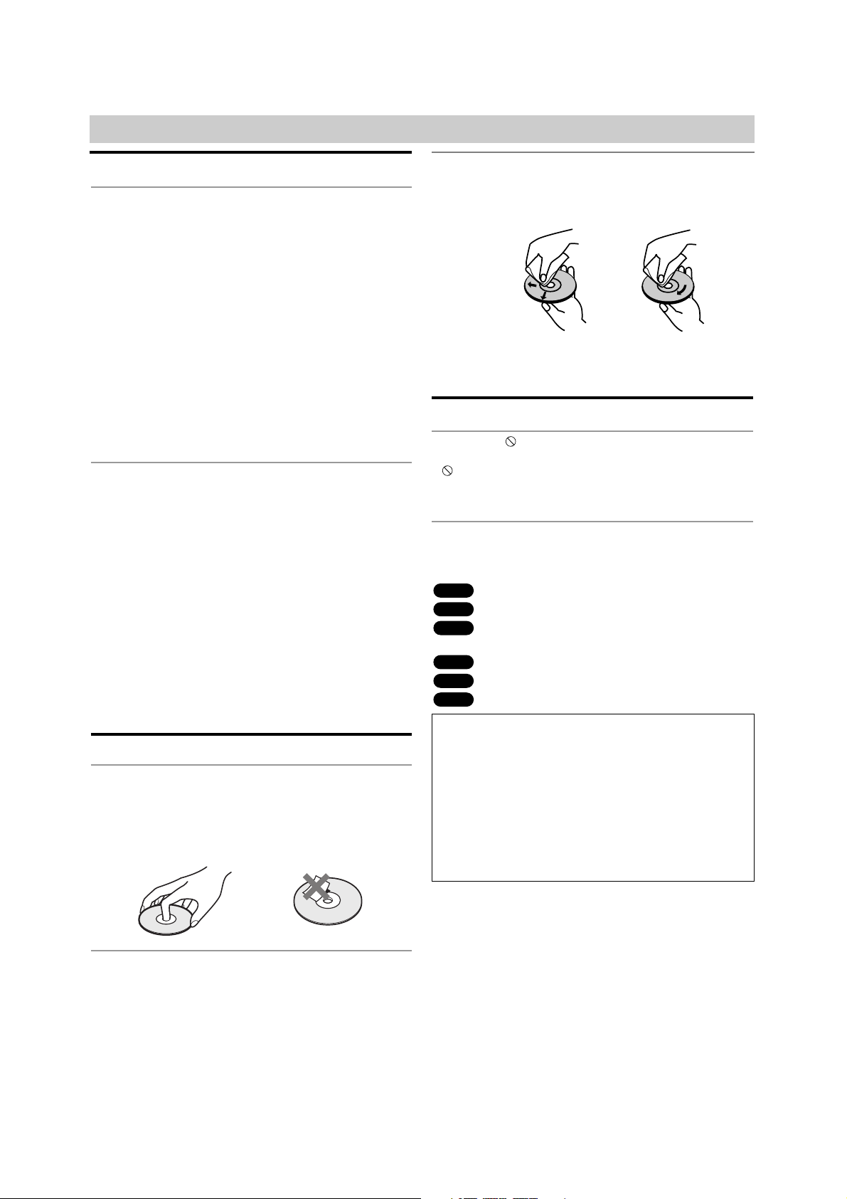
Handling discs
Do not touch the playback side of the disc.
Hold the disc by the edges so that fingerprints will not
get on the surface.
Do not stick paper or tape on the disc.
Storing discs
After playing, store the disc in its case.
Do not expose the disc to direct sunlight or sources of
heat, or leave it in a parked car exposed to direct sunlight, as there may be a considerable temperature
increase inside the car.
Cleaning discs
Fingerprints and dust on the disc can cause poor picture
quality and sound distortion. Before playing, clean the disc
with a clean cloth. Wipe the disc from the center out.
Do not use strong solvents such as alcohol, benzine,
thinner, commercially available cleaners, or anti-static
spray intended for older vinyl records.
About Symbols
About the symbol display
“ ” may appear on the TV screen during operation. This
icon means the function explained in this owner’s manual
is not available at that moment or with that specific DVD.
About the disc symbols for instructions
Asection whose title has one of the following symbols are
applicable only to those discs represented by the symbol.
DVD
Video CDs with the PBC (playback control) function.
Video CDs without the PBC (playback control)
function.
Audio CDs.
MP3 Discs.
JPEG Files.
Notes
If you insert a cassette tape without an erasure pre-
vention tab intact while the DVD/VCR Receiver is in
the DVD mode, the DVD/VCR Receiver will switch to
VIDEO function mode automatically.
You can always view the DVD playback using
S VIDEO and COMPONENT VIDEO OUT connections although DVD/VCR Receiver is set to other
function mode (VIDEO, Radio, etc.)
JPEG
MP3
CD
VCD1.1
VCD2.0
DVD
Selecting the Viewing Source
You must select one of your output sources (DVD or
VIDEO) to view on the TV screen.
• If you want to view DVD deck output source:
Press DVD on the remote or DVD/VIDEO on the front panel
until DVD indicator in the display window lights and output
source of DVD deck is viewed on the TV screen.
• If you want to view VIDEO deck output source:
Press VIDEO on the remote or DVD/VIDEO on the front
panel until VIDEO indicator in the display window lights and
output source of VIDEO deck is viewed on the TV screen.
Yes
No
7
INTRODUCTION
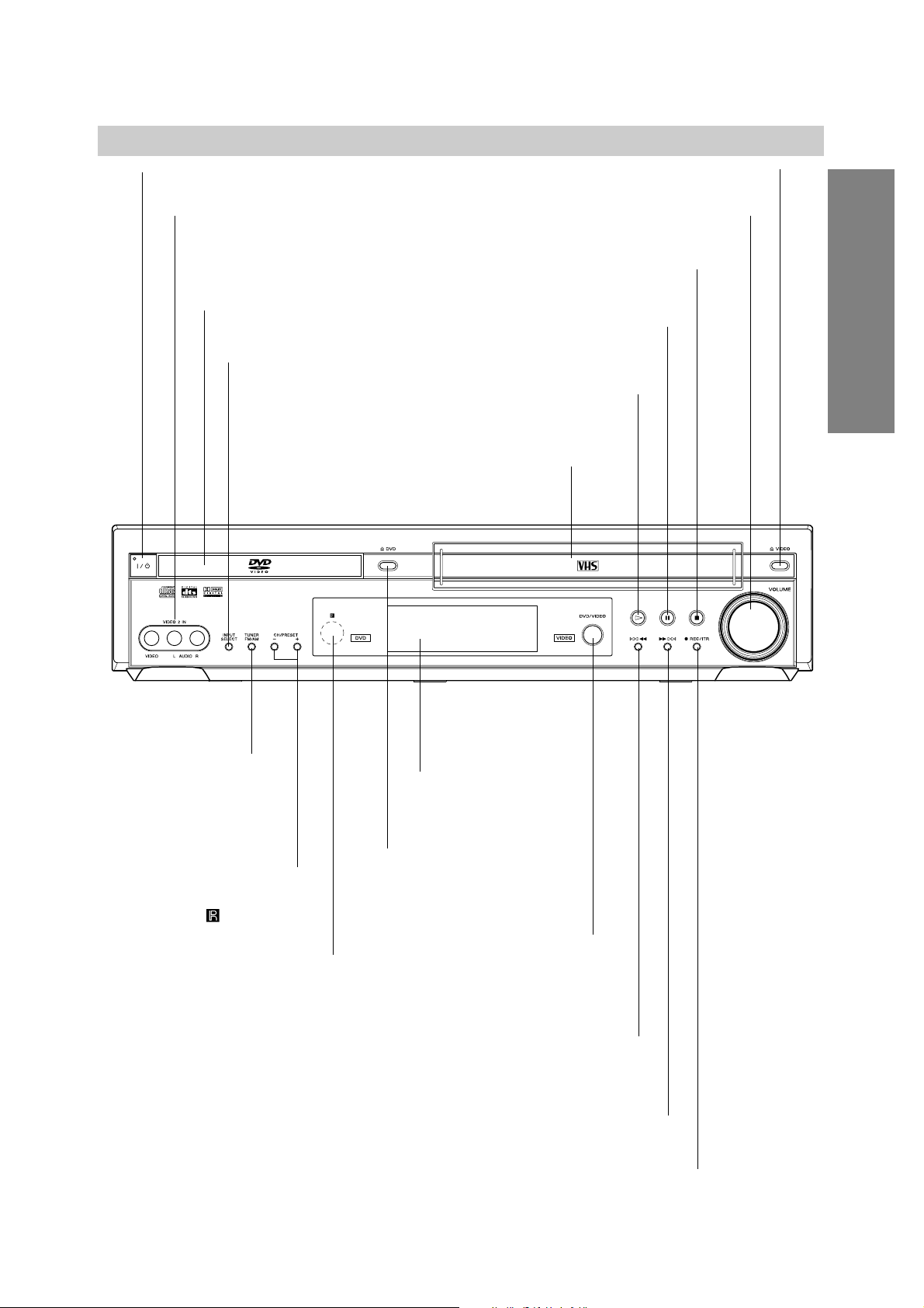
Front Panel
ML
DVD: Go to NEXT chapter/track. Press and hold for a fast forward search.
VIDEO: Advances the tape from STOP mode or for fast forward picture search.
X (PAUSE)
Pause playback or recording
temporarily.
z REC/ITR
To record normally or to activate Instant Timer Recording.
A DVD
Opens or closes
the disc tray.
Remote Sensor
Point the DVD/VCR Receiver remote
control here.
Display window
Shows the current status of the DVD/VCR
Receiver.
Disc Tray (DVD deck)
Insert a disc here.
@ / 1
Switches the DVD/VCR Receiver ON and OFF.
lm
DVD: Go to beginning of current chapter/track or to previous chapter/track.
Press and hold for a fast reverse search.
VIDEO: Rewinds the tape from STOP mode or for fast reverse picture search.
H (PLAY)
To play back a disc or
a recorded tape.
x (STOP)
Stops playback or recording.
INPUT SELECT
Selects the VIDEO deck’s
source (Tuner, VIDEO 1
or VIDEO 2).
CH/PRESET (+/–)
Scans up or down through
memorized channels or radio
frequencies (stations).
TUNER FM/AM
Selects Radio opera-
tion mode.
VIDEO 2 IN(VIDEO/AUDIO IN (Left/Right))
Connect the audio/video output of an
external source (Audio system, TV/ Monitor,
another VCR).
Video Cassette Compartment (VIDEO deck)
Insert a video cassette here.
A VIDEO
Ejects the tape in the VIDEO deck.
VOLUME
Adjusts sound level of speakers.
DVD/VIDEO
Toggles control
between the DVD deck
and the VIDEO deck.
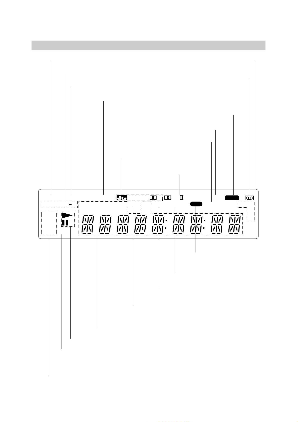
8
STEREO Indicates a stereo broadcast is being received.
DVD DVD inserted.
CD Audio CD inserted.
VCD Video CD inserted
MP3 MP3 disc inserted
Indicates repeat mode
ANGLE active
SHUFFLE Random playback active
A cassette is in the VIDEO deck.
SP EP Displays the recording
and playback speed.
HI-FI Indicates the unit is playing
back a tape recorded in Hi-Fi.
OPT Indicates source of DVD/VCR
Receiver is OPTICAL IN.
Indicates clock, total playing time, elapsed time, chapter number, track number,
channel, radio frequency, volume, channel or current deck status (Playback,
Pause, etc).
VIDEO DVD/VCR Receiver is recording.
SAP Indicates when a SAP BILINGUAL broadcast
is being received.
PBC Indicates PBC On mode
Indicates playback or pause mode.
TIMER DVD/VCR Receiver is in timer
recording or a timer recording is programmed.
REC DVD/VCR Receiver is
Recording.
PGM Programmed playback active.
Indicates encoding format of the
current disc.
Indicates sound mode is
DOLBY PROLOGIC II.
Display Window
SHUFFLE
REPEAT
PGM
1AB
STEREO
TITLE
CHAP
PCM
TRK SAP
AM
D
VIDEO
PL
REC
ANGLE
OPTTIMER
HI-FI
SP
MP3
DVD
VCDCHPBC
EP
9
INTRODUCTION
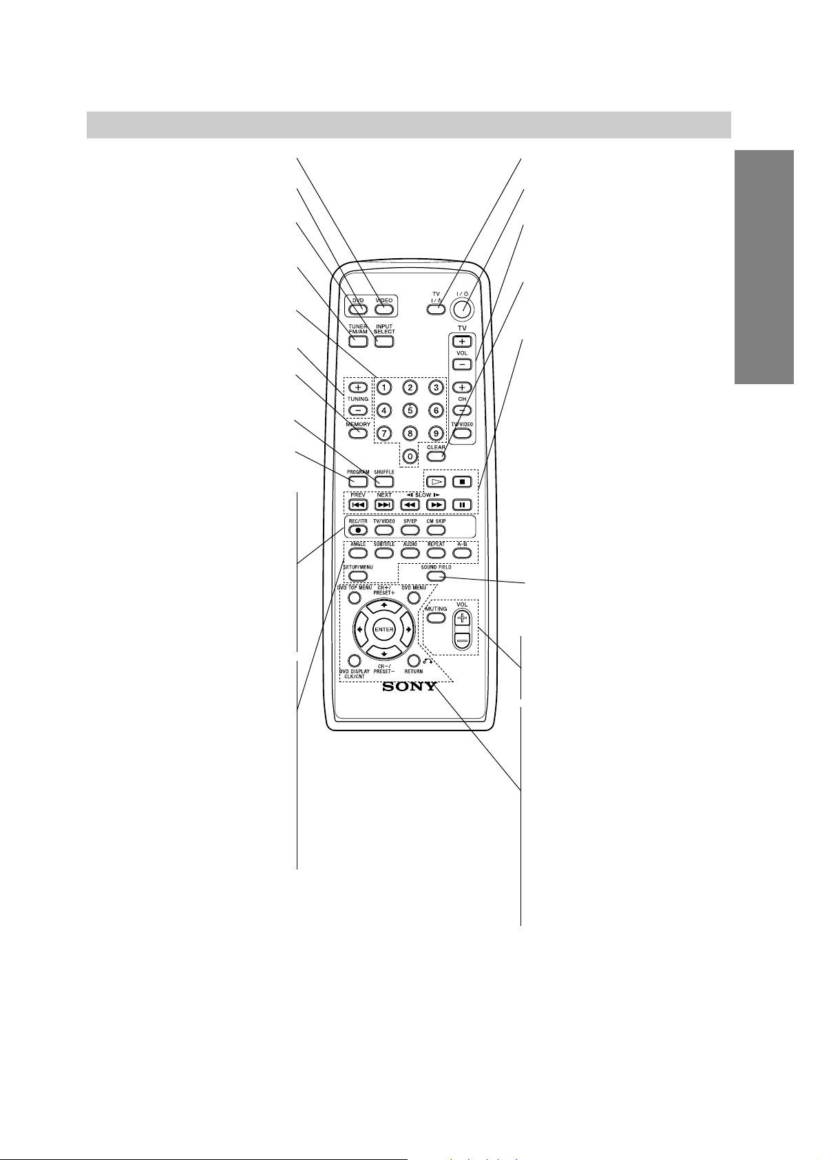
VIDEO
Select the output source to VIDEO.
DVD
Sets the output source to DVD.
INPUT SELECT
Selects the VIDEO deck’s source
(L1 OPT, LINE1, LINE2, Tuner).
TUNER FM/AM
Selects the DVD/VCR Receiver’s tuner as
the listening choice. (FM and AM bands)
0-9 numerical buttons
Selects numbered options in a menu.
TUNING (+/–)
To tune in the desired station.
MEMORY
Memorize a radio station frequency into
the tuner.
SHUFFLE
Plays tracks in random order.
PROGRAM
Enters to the program edit mode or exits
from that.
z REC/ITR
Records normally or activates Instant
Timer Recording.
TV/VIDEO
To view channels selected by the VIDEO
tuner or by the TV tuner.
SP/EP
Selects recording speed.
CM SKIP
Fast forwards picture search through 30
seconds of recording.
ANGLE
Selects a DVD camera angle if available.
SUBTITLE
Selects a subtitle language.
AUDIO
Selects an audio language (DVD) or an
audio channel (CD).
REPEAT
Repeat chapter, track, title, all.
A-B
Repeats sequence.
SETUP/MENU
Accesses or returns DVD setup menu
and VIDEO setup menu.
TV @ / 1
Switches TV ON and OFF.
@ / 1
Switches DVD/VCR Receiver ON and OFF.
TV Control Buttons (see page 40)
• VOL +/–: Adjusts TV’s volume.
• CH +/–: Selects TV’s channel.
• TV/VIDEO: Selects the TV’s source.
CLEAR
Removes a track number on the program
menu. To clear preset stations from the
tuner memory.
Playback Control Buttons
• H (PLAY)
Starts playback.
• x (STOP)
Stops playback.
• . (PREV) (DVD mode only)
Go to beginning of current chapter or
track or go to previous chapter or track.
• > (NEXT) (DVD mode only)
Go to next chapter or track.
• m/M (SLOW t/T)
DVD: For picture search or slow playback backward or forward.
VIDEO: Rewinds or advances the tape
in STOP mode or for picture search.
• X (PAUSE)
Pause playback or recording temporarily.
SOUND FIELD
Selects sound mode between BYPASS,
PRO LOGIC, PRO LOGIC II (MOVIE,
MUSIC, MATRIX) and 3D SURROUND.
VOL (+/-)
Adjusts speaker volume.
MUTING
Momentarily silence the speaker of the
DVD/VCR Receiver.
DVD TOP MENU
Displays the disc’s Title menu, if available.
DVD MENU
Accesses menu on a DVD disc.
B/b/V/v (left/right/up/down)
Selects an option in the menu.
CH/PRESET(+/–): Selects a program of
VIDEO or Tuner. Adjusts manually the
tape’s picture onscreen.
ENTER
Acknowledges menu selection.
DVD DISPLAY, CLK/CNT
Accesses On-Screen display. Switches
among the clock and tape counter.
RETURN
Returns the setup menu.
Note
This remote control uses the same buttons for VIDEO and DVD
functions (ex. PLAY).
To use the VIDEO, first press the VIDEO button.
To use the DVD, first press the DVD button.
Remote Control
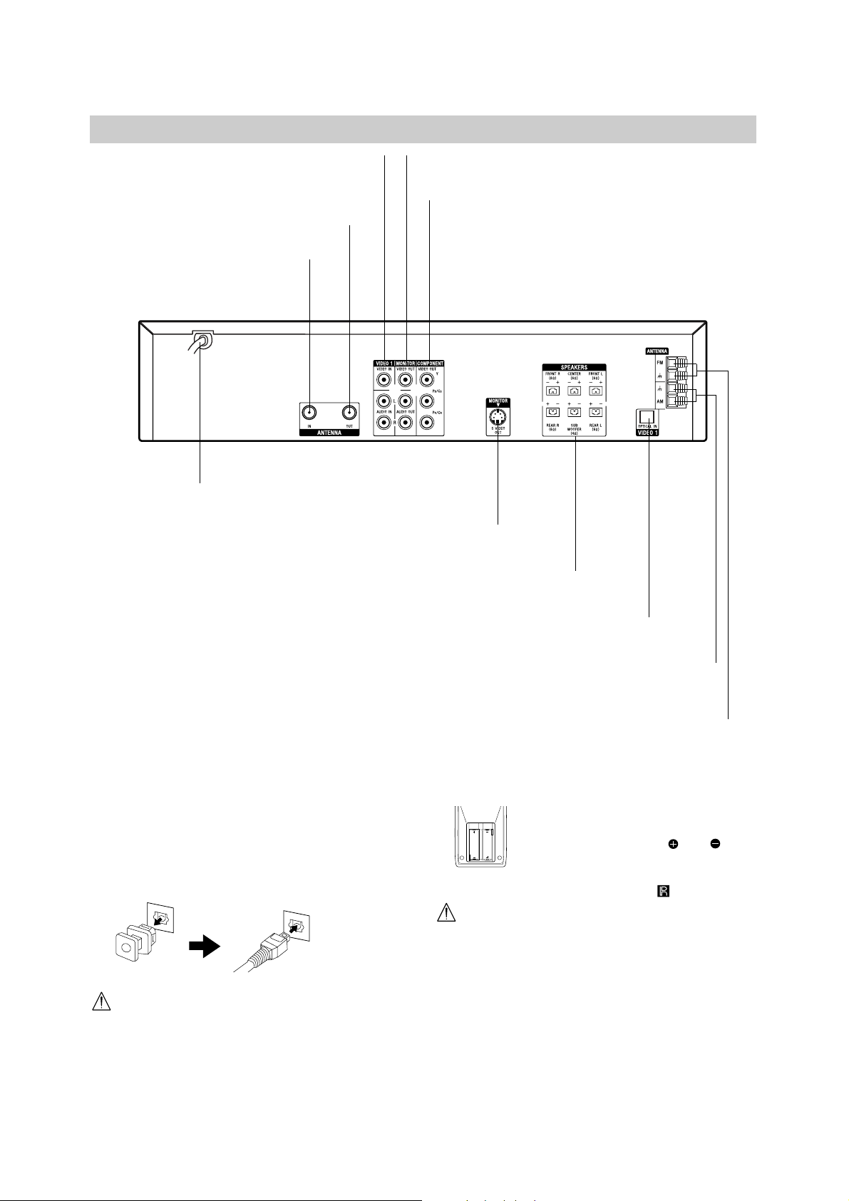
Rear Panel
10
Do not touch the inner pins of the jacks on the rear
panel. Electrostatic discharge may cause permanent
damage to the unit.
VIDEO 1 (VIDEO/AUDIO IN (Left/Right))
Connect the audio/video output of an external
source (Audio system, TV/Monitor, Another VCR).
ANTENNA IN
Connect the VHF/UHF/CATV
antenna to this terminal.
MONITOR (VIDEO / AUDIO OUT (Left/Right))
Connect to a TV with video and audio inputs.
AC Power Cord
Plug into the power source.
MONITOR S VIDEO OUT (DVD OUT)
Connect to a S Video Input on TV. FOR DVD VIEWING ONLY.
OPTICAL IN
Connect to a digital audio output on a digital device.
COMPONENT VIDEO OUT (Y P
B/CB PR/CR)
(DVD OUT)
Connect to a TV with Y P
B/CB PR/CR inputs. FOR DVD
VIEWING ONLY.
ANTENNA OUT (DVD/VIDEO OUT)
Connect to a TV with RF coaxial inputs.
AM ANTENNA Connectors
Connect the AM antenna to this terminal.
FM ANTENNA Connectors
Connect the FM antenna to this terminal.
SPEAKERS Connectors
Connect the six supplied speakers to these terminals.
Dust Protection Cap
Remove the dust protection cap from the OPTICAL IN
jack and connect the optical digital cable (not supplied)
securely so that the configurations of both the cable and
the connector match. Keep the dust protection cap and
always reattach the cap when not using the connector to
protect against dust intrusion.
Remote control battery installation
Detach the battery cover on the rear of
the remote control, and insert two R6
(size AA) batteries with and
aligned correctly.
When using the remote control, point it
at the remote sensor on the unit.
Caution
Do not mix old and new batteries. Never mix different
types of batteries (standard, alkaline, etc.).
AA
AA

Connections
11
PREPARATION
Tips
Depending on your TV and other equipment you wish to
connect, there are various ways you could connect the
DVD/VCR Receiver. Use connections described on pages
11-14.
Please refer to the manuals of your TV, VCR, Stereo
System or other devices as necessary to make the best
connections.
Caution
Make sure the DVD/VCR Receiver is connected directly to
the TV. Tune the TV to the correct video input channel.
Do not connect the DVD/VCR Receiver’s AUDIO OUT jack
to the phono in jack (record deck) of your audio system.
Do not connect your DVD/VCR Receiver via your VCR. The
DVD image could be distorted by the copy protection system.
Connecting Antenna/Cable TV to
DVD/VCR Receiver
1
Disconnect the antenna leads from the rear of the
TV.
2
Identify the type of cable from your antenna. If it is
a round cable as illustrated, it is a 75 ohm coaxial
antenna cable. This cable will connect directly to
the jack marked ANTENNA IN on your DVD/VCR
Receiver.
Tip
If your antenna lead wire is a flat type antenna cable,
connect it to an Antenna Adaptor (300-ohm to 75-ohm)
(not supplied) and slip the Adaptor onto the ANTENNA
IN jack. The Adaptor does not screw on to the
DVD/VCR Receiver, it just slips over the jack.
Without Cable Box
If your cable wire is connected to your TV without a converter
or descrambler box, unscrew the wire from your TV and attach
it to the ANTENNA IN jack on the DVD/VCR Receiver. Use the
supplied round coaxial cable to connect between the
DVD/VCR Receiver’s ANTENNA OUT jack and the 75 ohm
antenna input jack on the TV. With this connection, you can
receive all midband, super band, and hyperband channels.
With Cable Box
If a converter is required in your cable system, follow the
instruction below:
The cable hookup permits both TV and DVD/VCR Receiver
operation.
To view or record a CATV channel
1 Tune the TV to the DVD/VCR Receiver output channel (CH
3 or 4).
2 Set the DVD/VCR Receiver channel selector to the output
channel of the Cable Converter box using CH/PRESET (+/–)
or number (0-9) of your DVD/VCR Receiver. (Example: CH3)
3 Select the channel to view at the Cable Converter Box.
Notes
With this connection, you can not record one program while
viewing another.
If you are using a cable box to tune channels, it is not nec-
essary to do Auto Channel Programming, (Auto Channel
Search) as indicated on page 18.
Cable TV
Wall Jack
Back Panel of
Typical Cable Box
Antenna Antenna
Flat Wire
(300 ohm)
300/75 ohm
Adaptor
(Not supplied)
OR OR
Rear of DVD/VCR Receiver
Cable TV
Wall Jack
Rear of DVD/VCR Receiver

12
Connections (Continued)
Basic TV Connections
Make one of the following connections, depending on
the capabilities of your TV.
RF coaxial connection
Connect the ANTENNA OUT jack on the DVD/VCR
Receiver to the antenna in jack on the TV using the
75-ohm Coaxial Cable supplied (R).
Note
If you use this connection, tune the TV to the DVD/VCR
Receiver’s RF output channel (CH 3 or 4).
How to set the DVD/VCR Receiver’s RF output
channel
When the DVD/VCR Receiver is turned off,
press and
hold CH/PRESET(+/–) on the front panel for about five
seconds to change the RF output channel (CH 03 or
CH 04). “RF-03” or “RF-04” appears in the display window.
Audio/Video connection
1
Connect the VIDEO OUT jack on the DVD/VCR
Receiver to the video in jack on the TV using the
supplied video cable (V).
2
Connect the Left and Right AUDIO OUT jacks on
the DVD/VCR Receiver to the audio left/right in
jacks on the TV (A) using the supplied audio
cables.
Note
If you use this connection, set the TV’s source selector
to VIDEO.
Optional TV Connections
Note
DVD playback can ONLY be done using the S VIDEO
OUT and COMPONENT VIDEO OUT connection options
below.
The tuner and VIDEO will still output through the
ANTENNA OUT (R) or AUDIO/VIDEO OUT (A, V) jack.
(See left)
S Video Connection
1
Connect the S VIDEO OUT jack on the DVD/VCR
Receiver to the S Video in jack on the TV using the
supplied S Video cable (S).
2
Connect the Left and Right AUDIO OUT jacks on
the DVD/VCR Receiver to the audio left/right in
jacks on the TV using the supplied audio cables
(A).
Component Video (Color Stream®) connection
1
Connect the COMPONENT VIDEO OUT jacks on
the DVD/VCR Receiver to the corresponding in
jacks on the TV using a component video cables
(C).
2
Connect the Left and Right AUDIO OUT jacks of
the DVD/VCR Receiver to the audio left/right in
jacks on the TV (A) using the supplied audio
cables.
Progressive Scan (ColorStream®pro) connection
If your television is a high-definition or “digital ready”
television, you may take advantage of the DVD/VCR
Receiver’s progressive scan output for the highest
video resolution possible.
If your TV does not accept the Progressive Scan format, the picture will appear scrambled if you try
Progressive Scan on the DVD/VCR Receiver.
1
Connect the COMPONENT VIDEO OUT jacks on
the DVD/VCR Receiver to the corresponding in
jacks on the TV using a component video cables
(C).
2
Connect the Left and Right AUDIO OUT jacks of
the DVD/VCR Receiver to the audio left/right in
jacks on the TV (A) using the supplied audio
cables.
Notes
Set the Progressive Scan to “On” on the DVD setup
menu for progressive signal, see page 21.
Progressive scan does not work with the analog video
connections (yellow VIDEO OUT jack).
Rear of TV
ANTENNA
INPUT
AUDIO INPUT
L
R
VIDEO
INPUT
L
COMPONENT/PROGRESSIVE
SCAN VIDEO INPUT
Pr
Pb
Y
S VIDEO
INPUT
R
Rear of DVD/VCR Receiver
SA V C
13
PREPARATION
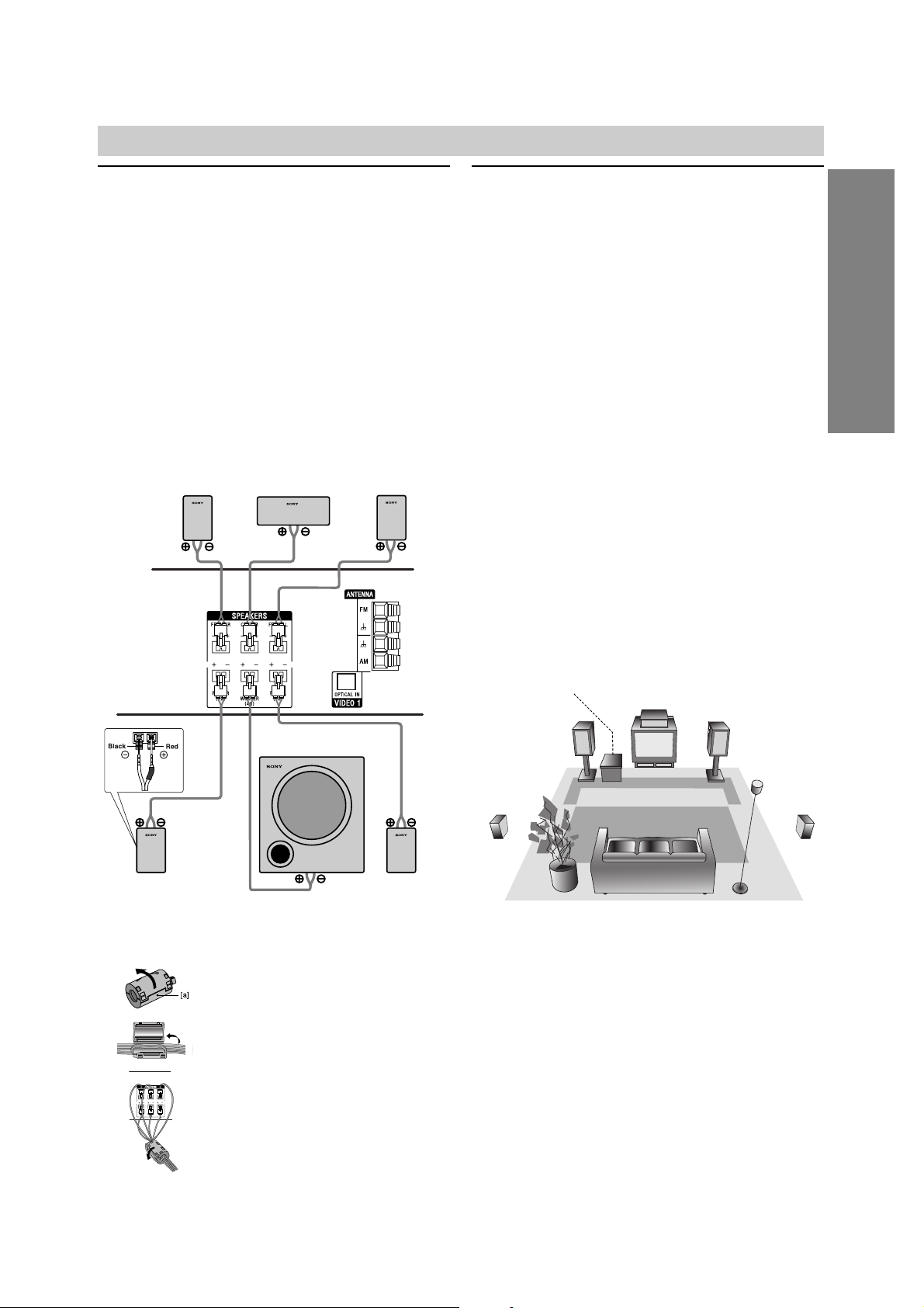
Connections (Continued)
Speaker System Connections
Connect the speakers using the supplied speaker cords
by matching the colors of the terminals and those of the
cords. To obtain the best possible surround sound,
adjust the speaker parameters (distance, level, etc.).
Notes
Be sure to match the speaker cord to the appropriate
terminal on the components: 3 to 3 and # to #. If
the cords are reversed, the sound will be distorted
and lack bass.
If you use front speakers with low maximum input rat-
ing, adjust the volume carefully to avoid excessive
volume output to the speakers.
Do not disassemble the front covers of supplied speakers.
Speaker Positioning
For a normal setup use 6 speakers (2 front speakers,
center speaker, 2 rear speakers and subwoofer).
•Front Speakers
Based on your listening position, set up the speakers
at equal distance. And by hearing position, set up an
interval between speakers of 45 degree.
• Center Speaker
It is ideal that the center speakers and front speakers
are same height. But normally place it above or below
the television as shown below.
• Rear Speakers
Place the rear surround speakers to the left and right
behind the primary listening area. These speakers
recreate sound motion and atmosphere required for
surround playback. For best results, do not install the
rear speakers too far behind the listening position,
install them at or above the level of the listener’s ears.
It is also effective to direct the rear speakers towards
a wall or ceiling to further disperse the sound.
In the case of a smaller room size, if the audience is
near to the rear wall set the rear speakers opposite
each other, and set the rear speakers 60 - 90 cm
above the listener’s ears.
• Subwoofer
This can be placed in any front position.
Note
Speaker stand is optional.
Center Speaker
Front
Speaker
(Left)
Speaker Positioning Example
Rear
Speaker
(Left)
Rear
Speaker
(Right)
Front
Speaker
(Right)
Subwoofer
Be sure to attach the ferrite core to
the speaker cables (for connecting to
this unit).
This ferrite core can reduce noises.
How to attach the ferrite core.
1 Push the stopper [a] of the ferrite core
to open.
2
Wind the Center and Subwoofer Speaker
cables once on the ferrite core.
Pass the others straight on the ferrite core.
3
Close the ferrite core until it clicks.
About Ferrite Core
1
2
3
Front Speaker
(Right)
Center
Speaker
Front Speaker
(Left)
Rear speaker
(Right surround)
Subwoofer
Rear speaker
(Left surround)
14
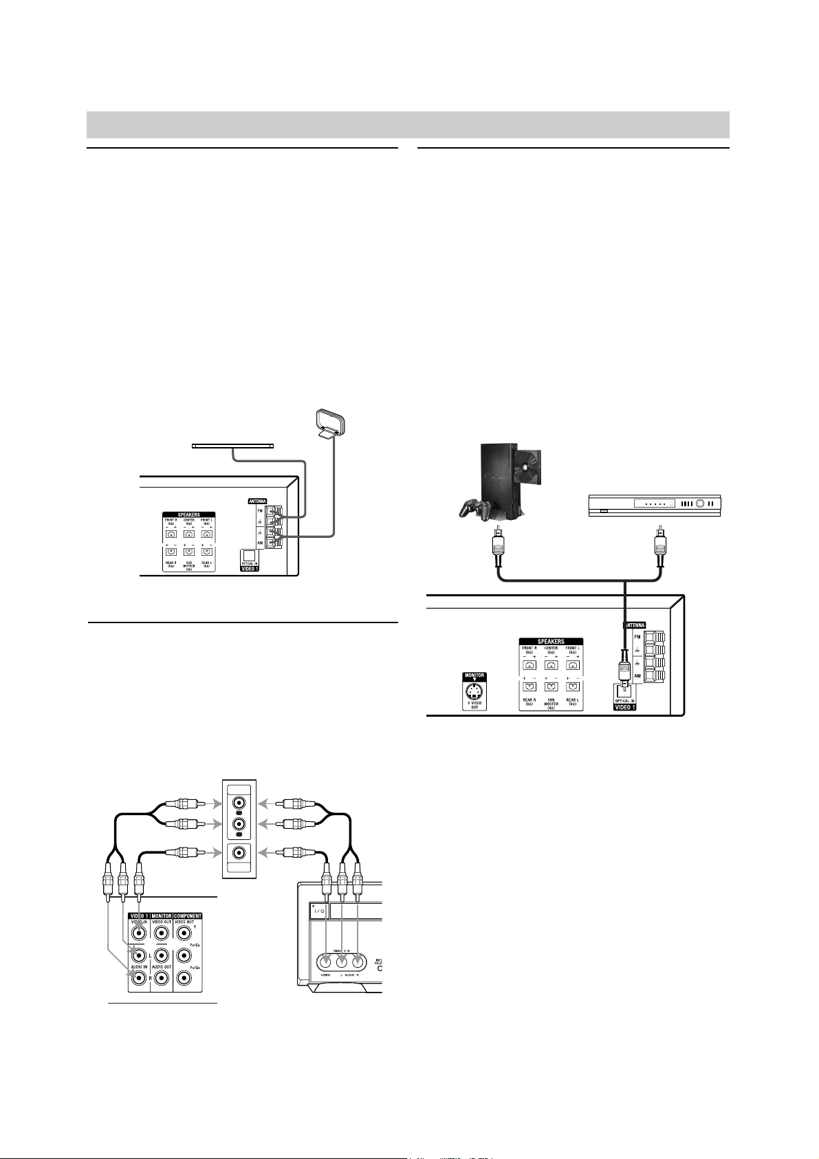
Radio Antenna Connections
Connect the supplied FM/AM antennas for radio listening.
1
Connect the AM loop antenna to the AM antenna
connectors.
2
Connect the FM wire antenna to the FM antenna
connectors.
Notes
To prevent noise pickup, keep the AM loop antenna
away from the DVD/VCR Receiver and other components.
Be sure to fully extend the FM wire antenna.
After connecting the FM wire antenna, keep it as hori-
zontal as possible.
Accessory Audio/Video (A/V)
Connections to DVD/VCR Receiver
Connect the VIDEO 1 or VIDEO 2 jacks on the
DVD/VCR Receiver to the audio/video out jacks on your
accessory component, using optional audio/video
cables.
Digital Device Connections
Connect the OPTICAL IN jacks on the DVD/VCR
Receiver to the digital audio out (optical) jacks on your
digital device (Game device, Digital Set Top Box, etc.),
using optional optical audio cable.
To select source of DVD/VCR Receiver to OPTICAL IN,
press INPUT SELECT repeatedly on the remote control
until “L1 OPT” appears in the display window.
Notes
If the audio format of the digital output does not
match the capabilities of your DVD/VCR Receiver, the
DVD/VCR Receiver will produce a strong, distorted
sound or no sound at all.
The Optical input function is available only when the
other unit’s Sampling Frequency is 32 - 48kHz.
Connections (Continued)
AM loop antenna (supplied)
FM wire antenna (supplied)
Game Device
Digital Set Top Box
Rear of DVD/VCR Receiver
Jack Panel of Accessory Component
(VCR, Camcorder, etc.)
AUDIO
OUTPUT
VIDEO
OUTPUT
R
L
OR
OR
Rear of DVD/VCR Receiver
Rear of
DVD/VCR Receiver
Front of
DVD/VCR Receiver
15
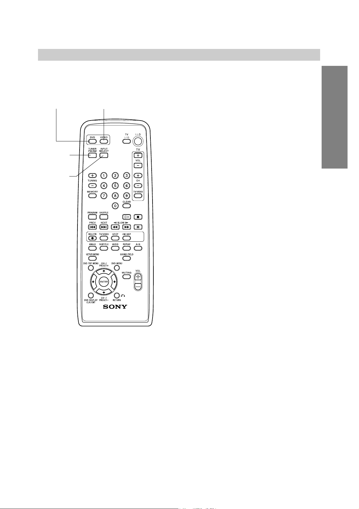
Follow these guidelines to select and switch among the
various DVD/VCR Receiver input and output sources:
• DVD
To view output from the DVD deck:
Press DVD on the remote or DVD/VIDEO on the
front panel until the DVD indicator on the front panel
lights and output from the DVD deck is viewed on the
TV screen.
• VIDEO
To view output from the VIDEO deck:
Press VIDEO on the remote or DVD/VIDEO on the
front panel until the VIDEO indicator on the front
panel lights and output from the VIDEO deck is
viewed on the TV screen.
• TUNER FM/AM
To listen to AM/FM radio broadcasts:
Press TUNER FM/AM to toggle between AM and FM
radio. The selected frequency appears in the display
window.
• INPUT SELECT
To listen and view to an audio source connected
to the OPTICAL IN jack with video from VIDEO 1:
Press INPUT SELECT on the remote control once.
The “L1 OPT” and “LINE 1” appears in the display
window and TV screen. Audio will come from an
external source connected to the OPTICAL IN jack
and video will come from an external source connected to the VIDEO IN jack of
VIDEO 1 (for rear panel).
To listen and view to an audio source connected
to the AUDIO IN jack of VIDEO 1 with video from
VIDEO 1:
Press INPUT SELECT on the remote control a second time. The “L1” and “LINE 1” appears in the display window and TV screen. Audio will come from an
external source connected to the AUDIO IN jacks of
VIDEO 1 (for rear panel) and video will come from an
external source connected to the VIDEO IN jack of
VIDEO 1 (for rear panel).
To listen and view to an audio source connected
to the AUDIO IN jack of VIDEO 2 with video from
VIDEO 2:
Press INPUT SELECT on the remote control a third
time. The “L2” and “LINE 2” appears in the display
window and TV screen. Audio will come from an
external source connected to the AUDIO/VIDEO IN
jacks of VIDEO 2 (for front panel).
Selecting the Output/Input Source
PREPARATION
DVD VIDEO
TUNER
FM/AM
INPUT
SELECT
 Loading...