

Sony HT-DDW8500, HT-DDW7500, HT-DDW8600, HT-DDW7600 Operating Instructions Manual

Home Theatre
System
4-138-609-15(1)
Operating Instructions
HT-DDW8500
HT-DDW7500
©2009 Sony Corporation
WARNING
To reduce the risk of fire or electric
shock, do not expose this apparatus to
rain or moisture.
To reduce the risk of fire, do not cover the
ventilation opening of the apparatus with
newspapers, tablecloths, curtains, etc. Do not place
the naked flame sources such as lighted candles on
the apparatus.
Do not install the appliance in a confined space, such
as a bookcase or built-in cabinet.
To reduce the risk of fire or electric shock, do not
expose this apparatus to dripping or splashing, and
do not place objects filled with liquids, such as
vases, on the apparatus.
As the main plug is used to disconnect the unit from
the mains, connect the unit to an easily accessible
AC outlet. Should you notice an abnormality in the
unit, disconnect the main plug from the AC outlet
immediately.
Do not expose batteries or apparatus with batteryinstalled to excessive heat such as sunshine, fire or
the like.
The unit is not disconnected from the mains as long
as it is connected to the AC outlet, even if the unit
itself has been turned off.
Excessive sound pressure from earphones and
headphones can cause hearing loss.
Note on power cord plug
shapes
(For customers in Saudi Arabia
only)
For AC 220 V wall sockets
1 Make the appropriate voltage setting on
the system (only for models with a
voltage selector).
2 Make sure that the 13 A 3-pin plug
(Type BF) is securely attached to the
power cord. (The 13 A 3-pin plug is
attached when shipped from the
factory).
For customers in Australia
Disposal of Old Electrical &
Electronic Equipment
(Applicable in the European
Union and other European
countries with separate
collection systems)
GB
2
About This Manual
D
D
• The instructions in this manual are for model
HT-DDW8500 and HT-DDW7500. Check your
model number by looking at the lower right corner
of the front panel. In this manual, models of area
code AU is used for illustration purposes unless
stated otherwise. Any difference in operation is
clearly indicated in the text, for example, “Models
of area code E51 only”.
• The instructions in this manual describe the
controls on the supplied remote. You can also use
the controls on the receiver if they have the same
or similar names as those on the remote.
The HT-DDW7500 consists of:
• Receiver STR-KM7500
• Power amplifier TA-KMSW500 (1)
• Speaker system
– Front speaker SS-MSP7500 (2)
– Center speaker SS-CNP7500 (1)
– Surround/Surround back speaker
– Subwoofer SS-WP7500 (2)
The HT-DDW8500 consists of:
• Receiver STR-KM7500
• Power amplifier TA-KMSW500 (2)
• Speaker system
– Front speaker SS-MSP7500 (2)
– Center speaker SS-CNP7500 (1)
– Surround/Surround back speaker
– Subwoofer SS-WP7500 (4)
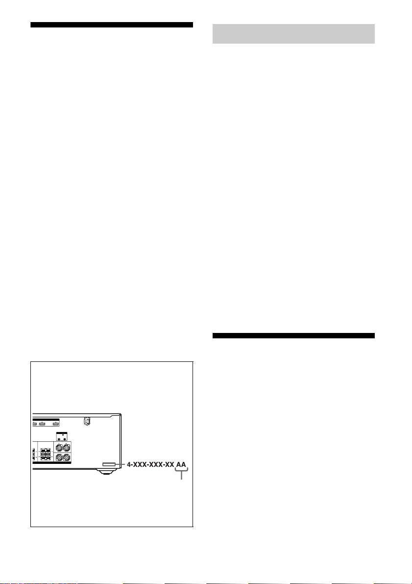
About area codes
The area code of the receiver you purchased is
shown on the lower right portion of the rear panel
(see the illustration below).
HDMI
VD IN BD IN OUT
SYSTEM CONTROL
DCSV
50mA MAX
OUT OUT
FRONT
SURROUND
L
BACK
LR
R
SPEAKERS
SS-SRP7500 (4)
SS-SRP7500 (4)
On Copyright
This receiver incorporates Dolby* Digital and Pro
Logic Surround and the DTS** Digital Surround
System.
* Manufactured under license from Dolby
Laboratories. Dolby, Pro Logic, and the doubleD symbol are trademarks of Dolby Laboratories.
** Manufactured under license under U.S. Patent
#’s: 5,451,942; 5,956,674; 5,974,380; 5,978,762;
6,226,616; 6,487,535; 7,003,467; 7,212,872 &
other U.S. and worldwide patents issued &
pending. DTS, DTS Digital Surround, ES, and
Neo:6 are registered trademarks and the DTS
logos, Symbol and DTS 96/24 are trademarks of
DTS, Inc. © 1996-2008 DTS, Inc. All Rights
Reserved.
This receiver incorporates High-Definition
Multimedia Interface (HDMI
TM
) technology.
HDMI, the HDMI logo and High-Definition
Multimedia Interface are trademarks or registered
trademarks of HDMI Licensing LLC.
“x.v.Color (x.v.Colour)” and “x.v.Color
(x.v.Colour)” logo are trademarks of Sony
Corporation.
“BRAVIA” is a trademark of Sony Corporation.
Note for the supplied remote
RM-AAU023 (Model of area code AU,
E51, SA, EA only)
RM-AAU021 (Model of area code CA
only)
The CATEGORY +/– and CATEGORY MODE
buttons on the remote are not available for the
receiver operation.
Area code
Any differences in operation, according to the area
code, are clearly indicated in the text, for example,
“Models of area code AA only”.
GB
3

Table of Contents
Description and location of parts...................6
Getting Started
1: Installing the speakers .............................16
2: Connecting the speakers and
subwoofers..............................................18
3: Connecting the TV ..................................22
4a: Connecting the audio components.........23
4b: Connecting the video components ........24
5: Connecting the antennas (aerials)............31
6: Preparing the receiver and the remote.....32
7: Calibrating the appropriate settings
automatically
(AUTO CALIBRATION) .......................33
8: Adjusting the speaker levels and balance
(TEST TONE) ........................................37
Enjoying Surround Sound
Enjoying Dolby Digital and DTS Surround
sound (AUTO FORMAT DIRECT)....... 55
Selecting a pre-programmed sound field.... 57
Using only the front speakers and the
subwoofers (2CH STEREO).................. 59
Enjoying the surround effect at low volume
levels (NIGHT MODE) ......................... 60
Resetting sound fields to the initial
settings ................................................... 60
Tuner Operations
Listening to FM/AM radio.......................... 61
(Except for models of area code EA only)
Presetting FM/AM radio stations................ 63
Playback
Selecting a component.................................39
Listening/Watching a component ................41
Amplifier Operations
Navigating through menus...........................43
Adjusting the level (LEVEL menu)............. 47
Adjusting the equalizer (TONE menu)........48
Settings for the surround sound
(SUR menu)............................................48
Settings for the tuner (TUNER menu).........50
Settings for the audio (AUDIO menu).........50
Settings for the HDMI (HDMI menu).........52
Settings for the system (SYSTEM menu) ...52
Calibrating the appropriate settings
automatically (A. CAL menu) ................54
GB
4
“BRAVIA” Sync Features
What is “BRAVIA” Sync?.......................... 64
Preparing for the “BRAVIA” Sync ............. 65
Watching a DVD (One-Touch Play) ........... 67
Enjoying the TV sound from the speakers
connected to the receiver
(System Audio Control)......................... 67
Turning off the receiver with the TV
(System Power Off) ............................... 68
Other Operations
Switching between digital and analog audio
(INPUT MODE) .................................... 69
Listening to digital sound from other inputs
(DIGITAL ASSIGN) ............................. 70
Enjoying the DIGITAL MEDIA PORT
(DMPORT) ............................................ 71
Changing the display .................................. 73
Using the Sleep Timer ................................ 73
Recording using the receiver....................... 74

Using the Remote
Changing button assignments ..................... 75
Additional Information
Glossary ...................................................... 76
Precautions .................................................. 78
Troubleshooting .......................................... 79
Specifications .............................................. 83
Index............................................................ 87
GB
5
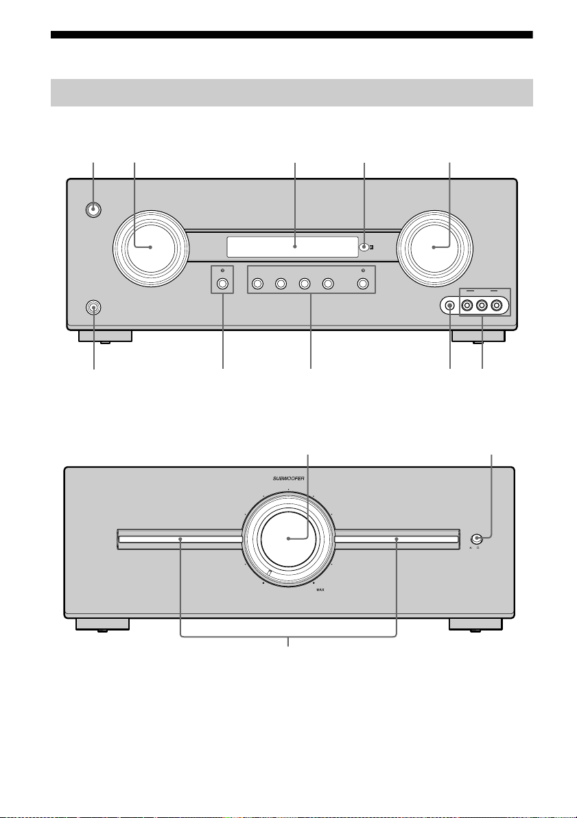
Description and location of parts
q
Front panel
Receiver
1 3 4 52
?/1
PHONES
Power amplifier
NIGHT MODE
9 8 60
MASTER VOLUMEINPUT SELECTOR
MOVIE
A.F.D.
MUSIC
MULTI STEREOGAME
VIDEO 2 IN
AUTO CAL MIC
VIDEO
L AUDIO R
7
qa
VOLUME
MIN
qs
ILLUMINATION
ON OFF
d
GB
6

Name Function
A ?/1
(on/standby)
B INPUT
SELECTOR
C Display The current status of the
D Remote sensor Receives signals from
E MASTER
VOLUM E
F VIDEO 2 IN jacks Connect to a portable
G AUTO CAL MIC
jack
H A.F.D. Press to select a sound
MOVIE
MUSIC
GAME
MULTI STEREO
MULTI STEREO
lamp
I NIGHT MODE Press to enjoy sound
NIGHT MODE
lamp
J PHONES jack Connects to headphones
K SUBWOOFER
VOLUM E
Press to turn the receiver
on or off (page 32, 41, 42,
60, 65).
Turn to select the input
source to play back (page
39, 41, 63, 64).
selected component or a
list of selectable items
appears here (page 8).
remote commander.
Turn to adjust the volume
level of all speakers at the
same time (page 38, 39,
41, 42).
audio/video component
such as a camcorder or
video game (page 30, 36).
Connects to the supplied
optimizer microphone for
the Auto Calibration
function (page 34).
field (page 55).
Lights up when multi
stereo sound field is
activated.
effects for watching movie
at night (page 45, 51, 60).
Lights up when NIGHT
MODE is activated.
(page 79).
Turn to adjust the volume
level of the subwoofers.
Name Function
L ILLUMINATION
M Illumination
indicator
ON
The illumination is on
(initial setting).
OFF
The illumination is off.
Lights up to indicate the
subwoofer output level.
GB
7
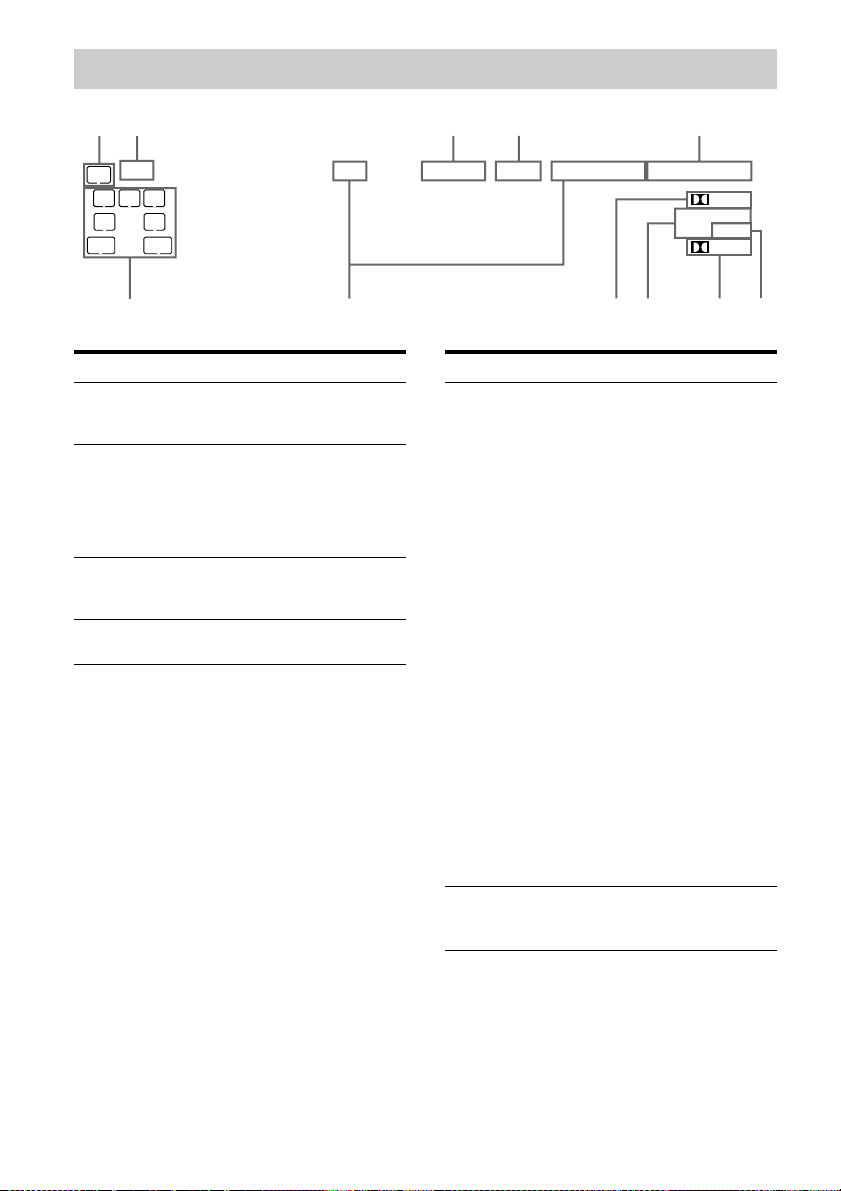
About the indicators on the display
12 3 4 5
LFE
SW
LC
SL S
SBSBL SBR
qa
R
SR
MEM
Name Function
A SW Lights up when the audio signal
B LFE Lights up when the disc being
C D.RANGE Lights up when dynamic range
D SLEEP Lights up when the sleep timer
is output from the
SUBWOOFER jack.
played back contains an LFE
(Low Frequency Effect)
channel and the LFE channel
signal is actually being
reproduced.
compression is activated
(page 47).
is activated.
D.RANGE
SLEEP FM AM ST
HDMI COAX
DTS -ES
96/24
Name Function
E Input
indicators
HDMI
COAX
OPT
F NEO:6 Lights up when DTS Neo:6
Light up to indicate the current
input.
Lights up when the receiver
recognizes a component
connected via an HDMI IN
jack.
Lights up when INPUT MODE
is set to “AUTO” and the source
signal is a digital signal is input
through the COAXIAL jack or
when INPUT MODE is set to
“COAX”. However, “NO
INPUT” appears on the display
when INPUT MODE is set to
“COAX” and no digital signal
is input through the COAXIAL
jack (page 69).
Lights up when INPUT MODE
is set to “AUTO” and the source
signal is a digital signal is input
through the OPTICAL jack or
when INPUT MODE is set to
“OPT”. However, “NO
INPUT” appears on the display
when INPUT MODE is set to
“OPT” and no digital signal is
input through the OPTICAL
jack (page 69).
Cinema/Music decoder is
activated (page 56).
OPT
D EX
NEO:6
PL IIx
76890
GB
8
Name Function
G Dolby
Pro Logic
indicators
PL
Lights up one of the respective
indicators when the receiver
applies Dolby Pro Logic
processing to 2 channel signals
in order to output the center and
surround channel signals.
Dolby Pro Logic
PLII
PLIIx
H DTS(-ES)
indicators
DTS
DTS-ES
DTS 96/24
I Dolby Digital
Surround
indicators
D
D EX
Dolby Pro Logic II
Dolby Pro Logic IIx
Note
Dolby Pro Logic IIx decoding
does not function for DTS
format signals or for signals
with a sampling frequency of
more than 48 kHz.
Light up when DTS or DTS-ES
signals are input.
Lights up when the receiver is
decoding DTS signals.
Lights up when the receiver is
decoding DTS-ES signals.
Lights up when the receiver is
decoding DTS 96/24 (96 kHz/
24 bit) signals.
Note
When playing a DTS format
disc, be sure that you have made
digital connections and that
INPUT MODE is not set to
“ANALOG” (page 69).
Lights up one of the respective
indicators when the receiver is
decoding the corresponding
Dolby Digital format signals.
Dolby Digital
Dolby Digital Surround EX
Note
When playing a Dolby Digital
format disc, be sure that you
have made digital connections
and that INPUT MODE is not
set to “ANALOG” (page 69).
Name Function
J Tuning
indicators
MEM
FM
AM
ST
K Playback
channel
indicators
L
R
C
SL
SR
S
SBL
SBR
SB
Lights up when the receiver
tunes in radio stations.
Lights up when a memory
function, such as Preset
Memory (page 63), etc., is
activated.
Lights up when FM band is
selected.
Lights up when AM band is
selected.
Lights up when stereo broadcast
is selected.
The letters (L, C, R, etc.)
indicate the channels being
played back. The boxes around
the letters vary to show how the
receiver downmixes the source
sound.
Front Left
Front Right
Center (monaural)
Surround Left
Surround Right
Surround (monaural or the
surround components obtained
by Pro Logic processing)
Surround Back Left
Surround Back Right
Surround back (the surround
back components obtained by
6.1 channel decoding)
Example:
Recording format (Front/
Surround): 3/2.1
Sound Field: A.F.D. AUTO
LFE
SW
LCSLR
SR
continued
GB
9
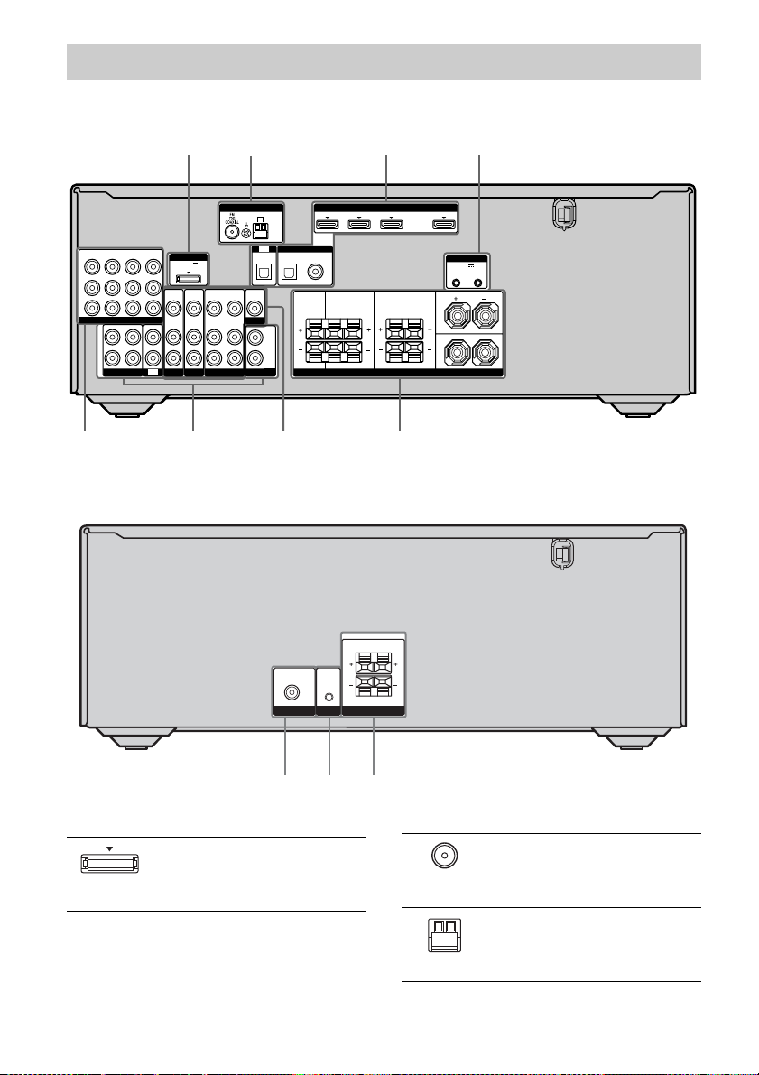
Rear panel
7 4 5
Receiver
1 2 3 4
SAT
DVDINVIDEO 1INMONITOR
IN
Y
P
B
/
C
B
P
R
/
C
R
COMPONENT VIDEO
OUT
IN
L
R
SA-CD/CD/CD-R
OUT
DMPORT
DC5V
0.7A MAX
VIDEO
VIDEO
IN
IN
AUDIO
AUDIO
IN
IN
IN
TV
SAT
BD
Power amplifier
VIDEO
OUT
AUDIO
OUT
VIDEO 1
ANTENNA
VIDEO
IN
AUDIO
IN
OPTICAL
VIDEO
OUT
MONITOR
SUBWOOFER
AM
TV
A
UDIO
OUT
SAT IN DVD IN BD IN OUT
(ASSIGNABLE)
DIGITAL
SATINDVD
IN
IN
OPTICAL COAXIAL
CENTER SURROUND BACK
L
R
SUBWOOFER ONLY FOR SS-WP7500
AUDIO
IN
IN
SYSTEM
SUBWOOFER SPEAKERS
CONTROL
SUBWOOFER
HDMI
SURROUND
SPEAKERS
568 7
SYSTEM CONTROL
DCSV
50mA MAX
OUT OUT
FRONT
L
LR
R
A DMPORT
GB
10
DMPORT
jack
Connects to a
DIGITAL MEDIA
PORT adapter (page
71).
B ANTENNA section
FM
ANTENNA
jack
AM
ANTENNA
terminals
Connects to the
supplied FM wire
antenna (aerial)
(page 31).
Connects to the
supplied AM loop
antenna (aerial)
(page 31).
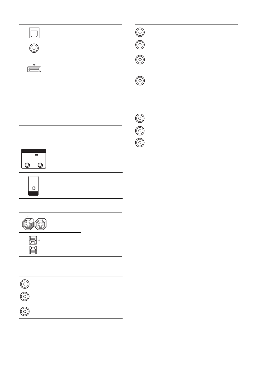
C DIGITAL INPUT/OUTPUT section
OPTICAL
IN jacks
COAXIAL IN
jack
HDMI IN/
OUT* jacks
Connects to a DVD
player, etc. The
COAXIAL jack
provides a better
sound quality (page
28, 29).
Connects to a DVD
player, satellite
tuner, or a Blu-ray
disc player. The
image is output to a
TV or projector
while the sound can
be output from a TV
or/and speakers
connected to this
receiver (page 26).
D SYSTEM CONTROL INPUT/OUTPUT
section
SYSTEM CONTROL
DCSV
50mA MAX
OUT OUT
IN
SYSTEM
CONTROL
SYSTEM
CONTROL
OUT jacks
SYSTEM
CONTROL IN
jack
Connects to the
power amplifier
(page 20).
Connects to the
receiver (page 20).
G AUDIO INPUT/OUTPUT section
White (L)
Red (R)
Black
Black
AUDIO IN/
OUT jacks
AUDIO OUT
jack
AUDIO IN
jack
Connects to a Super
Audio CD player,
CD recorder, etc.
(page 23).
Connects to the
power amplifier
(page 18).
Connects to the
receiver.
H COMPONENT VIDEO INPUT/
OUTPUT section
B/CB)
R/CR)
Y, PB/CB,
P
R/CR IN/
OUT* jacks
Green
(Y)
Blue
(P
Red
(P
* You can watch the selected input image when you
connect the MONITOR OUT or HDMI OUT jack
to a TV or projector (page 22).
Connects to a DVD
player, TV, satellite
tuner, etc. You can
enjoy high quality
image (page 22–30).
E SPEAKERS section
Connects to the
speakers (page 18).
F VIDEO/AUDIO INPUT/OUTPUT
section
White (L)
Red (R)
Yellow
AUDIO
IN/OUT jacks
VIDEO
IN/OUT* jacks
Connects to a VCR,
Blu-ray disc player,
etc. (page 22–30).
11
GB
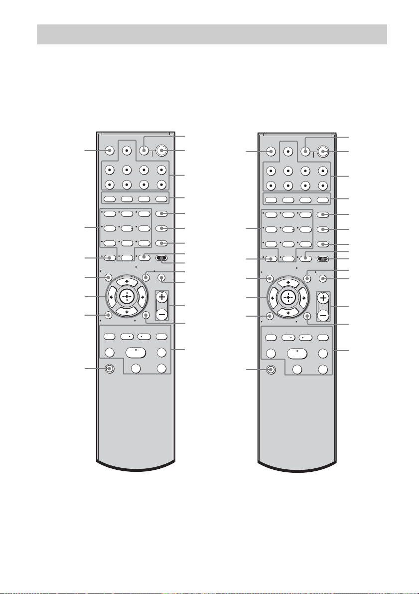
Remote commander
You can use the supplied RM-AAU021 (Model of area code CA only) or RM-AAU023 (Model of
area code AU, E51, SA, EA only) Remote Commander to operate the receiver and to control the
Sony audio/video components that the remote is assigned to operate (page 75).
RM-AAU021
(Model of area code CA only)
wa
w;
ql
qk
qj
qh
qg
DISPLAY
PRESET –
TV INPUT
SLEEP
VIDEO1 VIDEO2 BD DVD
SAT TV SA-CD/CD TUNER
2CH A.F.D.
>10
CLEAR
O
RETURN/EXIT
TV CH –
.
TUNING –
TV
?/1
DMPORT
123
46
78
TV
AV
?/1
SYSTEM STANDBY
MOVIE MUSIC
THEATER
5
AUTO CAL
D.TUNING
9
0/10
– CATEGORY +
REPLAY ADVANCE
<
CATEGORY MODE
AMP MENUMEMORY
ENTER
TOOLS/
OPTIONS
MASTER VOL
MENU/HOME
PRESET +
<
TUNING +
HmM
FM MODE
Xx
?/1
DVD/BD
MENU
D.SKIP
MUTING
TV VOL
TV CH +
>
1
2
3
4
5
6
7
8
9
0
qa
qs
qd
qf
RM-AAU023
(Model of area code AU, E51,
SA, EA only)
>
1
?/1
2
3
4
5
6
7
8
9
q;
qa
qs
qd
qf
wa
w;
ql
qk
qj
qh
qg
TV INPUT
DISPLAY
RETURN/EXIT
TV CH –
PRESET –
TUNING –
TV
?/1
DMPORT
SLEEP
VIDEO1 VIDEO2 BD DVD
SAT TV SA-CD/CD TUNER
2CH A.F.D.
123
46
78
>10
-
CLEAR
O
REPLAY ADVANCE
.
TV
AV
?/1
SYSTEM STANDBY
MOVIE MUSIC
THEATRE
DVD/BD
5
0/10
<
MENU
AUTO CAL
D.TUNING
9
D.SKIP
AMP MENU
MEMORY
ENTER
TOOLS/
MUTING
OPTIONS
TV VOL
MASTER VOL
MENU/HOME
TV CH +
PRESET +
<
TUNING +
HmM
FM MODE
Xx
12
GB

Name Function
A TV ?/1
(on/standby)
AV ?/1
(on/standby)
B ?/1
(on/standby)
C Input buttons Press one of the buttons to
D 2CH Press to select a sound field.
A.F.D.
MOVIE
MUSIC
E THEATER
(RM-AAU021
only)
THEATRE
(RM-AAU023
only)
Press TV ?/1 and TV (O) at
the same time to turn the TV
on or off.
Press to turn on or off the
Sony audio/video components
that the remote is assigned to
operate (page 75).
If you press ?/1 (B) at the
same time, it will turn off the
receiver and other Sony
components (SYSTEM
STANDBY).
Note
The function of the AV ?/1
switch changes automatically
each time you press the input
buttons (C).
Press to turn the receiver on or
off.
To turn off all Sony
components, press ?/1 and
AV ?/1 (A) at the same time
(SYSTEM STANDBY).
select the component you
want to use. When you press
any of the input buttons, the
receiver turns on. The buttons
are factory assigned to control
Sony components.
You can change the button
assignments following the
steps in “Changing button
assignments” on page 75.
Press to enjoy optimal image
suited for movies and to
output the sound from the
speakers connected to this
receiver automatically.
Note
This button will only function
if your TV is compatible with
Theatre Mode.
Refer to the operating
instructions supplied with the
TV for details.
Name Function
F DVD /BD
MENU
AUTO CAL Press to activate the Auto
G D.TUNING Press to enter direct tuning
D.SKIP Press to skip a disc when
ENTER Press to enter the value after
H
MEMORY Press to store a station.
I AMP MENU Press to display the menu of
J TOOLS/
OPTIONS
K MUTING Press to turn off the sound
L TV VOL
a)
+
/–
MASTER
a)
VOL +
Press to display the menu of
the DVD or Blu-ray disc on
the TV screen. Then, use V, v,
B, b and (Q) to perform
menu operations.
Calibration function.
mode.
using a multi-disc changer.
selecting a channel, disc or
track using the numeric
buttons of the TV, VCR or
satellite tuner.
the receiver. Then, use V, v,
B, b and (Q) to perform
menu operations.
Press to display and select the
options of the DVD player or
Blu-ray disc player.
Press TOOLS/OPTIONS and
TV (O) at the same time to
display the options applicable
to the Sony TV.
temporarily.
Press MUTING again to
restore the sound.
Press MUTING and TV (O)
at the same time to activate
the TV’s muting function.
Press TV VOL +/– and TV
(O) at the same time to adjust
the volume level of the TV.
Press to adjust the volume
/–
level of all speakers at the
same time.
continued
13
GB
Name Function
M MENU/HOME Press to display the menu of
N ./>
REPLAY /
ADVANCE
m/M
a)b)
H
b)
X
b)
x
TV CH +/– Press TV CH +/– and TV (O)
PRESET +/– Press to select
TUNING +/– Press to scan a station.
FM MODE Press to select the FM
the VCR, DVD player,
satellite tuner or Blu-ray disc
player on the TV screen.
Press MENU/HOME and TV
(O) at the same time to
display the TV’s menu.
Then, use V, v, B, b and
(Q) to perform menu
operations.
b)
Press to skip a track of the CD
player, DVD player or Blu-ray
disc player.
<
Press to replay the previous
<
scene or fast forward the
current scene of the VCR,
DVD player or Blu-ray disc
player.
b)
Press to
– search tracks in the forward/
reverse direction of the DVD
player.
– start fast forward/rewind of
the VCR, CD player or Bluray disc player.
Press to start playback of the
VCR, CD player, DVD player
or Blu-ray disc player.
Press to pause playback or
recording of the VCR, CD
player, DVD player or Blu-ray
disc player. (Also starts
recording with components in
recording standby.)
Press to stop playback of the
VCR, CD player, DVD player
or Blu-ray disc player.
at the same time to select
preset TV channels.
– preset stations.
– preset channels of the VCR
or satellite tuner.
monaural or stereo reception.
Name Function
O TV Press TV and the button with
P RETURN/
EXIT O
Q
,
V/v/B/b
R DISPLAY Press to select information
orange printing at the same
time to enable TV operation.
Press to
– return to the previous menu.
– exit the menu while the
menu or on-screen guide of
the VCR, DVD player,
satellite tuner or Blu-ray
disc player is displayed on
the TV screen.
Press RETURN/EXIT O
and TV (O) at the same time
to return to the previous menu
or exit the TV’s menu while
the menu is displayed on the
TV screen.
After pressing DVD/BD
MENU (F), AMP MENU
(I), or MENU/HOME (M),
press V, v, B or b to select the
settings. Then, press to
enter the selection if you have
pressed DVD/BD MENU or
MENU/HOME previously.
Press also to enter the
selection of the receiver,
VCR, satellite tuner, CD
player, DVD player or Bluray disc player.
displayed on the TV screen of
the VCR, satellite tuner, CD
player, DVD player or Bluray disc player.
Press DISPLAY and TV (O)
at the same time to display
TV’s information on the TV
screen.
14
GB

Name Function
S z
(RM-AAU021
only)
-/--
(RM-AAU023
only)
>10 Press to select the track
CLEAR Press to clear a mistake when
T Numeric
buttons
(number 5
U TV INPUT Press TV INPUT and TV (O)
SLEEP Press to activate the Sleep
a)
The number 5, TV VOL +, MASTER VOL + and
H buttons have tactile dots. Use the tactile dots as
references when operating the receiver.
b)
This button is also available for DIGITAL MEDIA
PORT adapter operation. For details on the
function of the button, refer to the operating
instructions supplied with the DIGITAL MEDIA
PORT adapter.
Press to input the decimal
point for channel numbers of
the Digital CATV terminal.
Press
z and TV (O) at the
same time to input the decimal
point for the channel numbers
of the TV.
Press to select the channel
entry mode, either one or two
digits of the VCR.
Press -/-- and TV (O) at the
same time to select the
channel entry mode, either
one or two digits of the TV.
numbers over 10 of the CD
player.
you press the incorrect
numeric button.
Press to
– preset/tune to preset
a)
)
stations.
– select track numbers of the
CD player, DVD player or
Blu-ray disc player. Press
0/10 to select track number
10.
– select channel numbers of
the VCR or satellite tuner.
Press the numeric buttons and
TV (O) at the same time to
select the TV channels.
at the same time to select the
input signal (TV input or
video input).
Timer function and the
duration which the receiver
turns off automatically.
Notes
• The CATEGORY +/– and CATEGORY MODE
buttons on the remote (RM-AAU021) are not
available for the receiver operation.
• Some functions explained in this section may not
work depending on the model.
• The above explanation is intended to serve as an
example only. Therefore, depending on the
component, the above operation may not be
possible or may operate differently than described.
15
GB
Getting Started
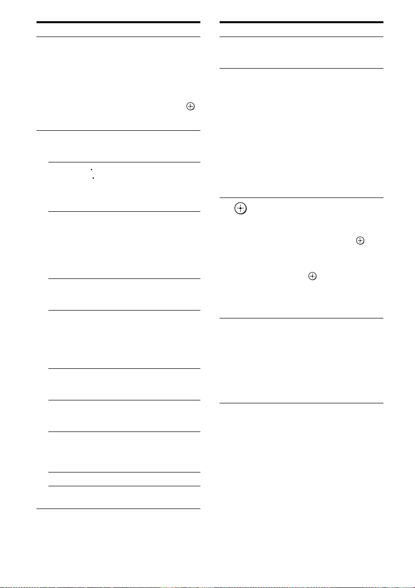
1: Installing the speakers
HT-DDW7500 only
This receiver allows you to use a 7 channel
speaker with 2 subwoofer system.
Example of a 7 channel speaker
with 2 subwoofer system
configuration
1
/
?
AFront speaker (left)
BFront speaker (right)
CCenter speaker
DSurround speaker (left)
ESurround speaker (right)
FSurround back speaker (left)
GSurround back speaker (right)
HSubwoofer
ISubwoofer
HT-DDW8500 only
This receiver allows you to use a 7 channel
speaker with 4 subwoofer system.
Example of a 7 channel speaker
with 4 subwoofer system
configuration
1
/
?
AFront speaker (left)
BFront speaker (right)
CCenter speaker
DSurround speaker (left)
ESurround speaker (right)
FSurround back speaker (left)
GSurround back speaker (right)
HSubwoofer
ISubwoofer
JSubwoofer
KSubwoofer
16
GB
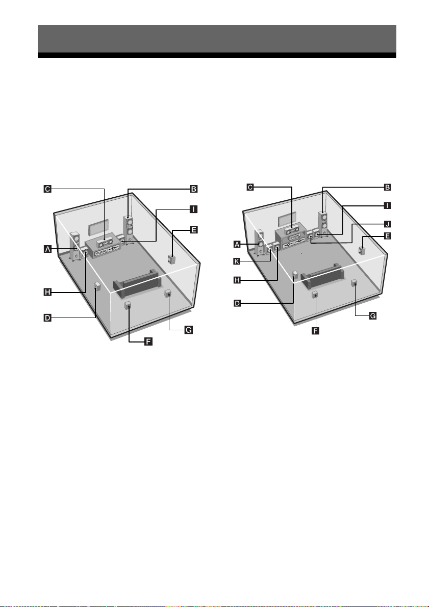
Installing the speakers on a flat
surface
Before you install the center speaker, surround
speakers, surround back speaker and
subwoofers, be sure to attach the supplied foot
pads to prevent vibration or movement as
shown in the illustration below.
Installing the speakers on the
wall
You can install your surround and surround
back speakers on the wall.
2 Fasten the screws to the wall.
The screws should protrude 5
to 7 mm (7/32 to 9/32 inch).
5 to 7 mm
(7/32 to 9/32 inch)
3 Hang the speakers on the
screws.
Hook on the back of the speaker
4.6 mm
(3/16 inch)
10 mm
(13/32 inch)
Getting Started
1 Prepare screws (not supplied)
that are suitable for the hook on
the back of each speaker as
shown in the illustrations
below.
4 mm (3/16 inch)
more than 25 mm (1 inch)
4.6 mm
(3/16 inch)
10 mm
(13/32 inch)
Hook on the back of the speaker
Notes
• Use screws that are suitable for the wall material
and strength. As a plaster board wall is especially
fragile, attach the screws securely to a beam and
fasten them to the wall. Install the speakers on a
vertical and flat wall where reinforcement is
applied.
• Contact a screw shop or installer regarding the wall
material or screws to be used.
• Sony is not responsible for accident or damage
caused by improper installation, insufficient wall
strength or improper screw installation, natural
calamity, etc.
17
GB
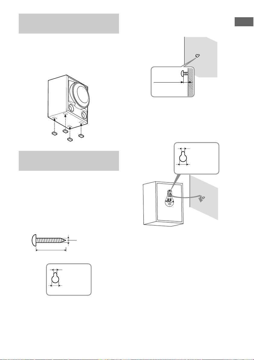
2: Connecting the speakers and subwoofers
DIGITAL
(ASSIGNABLE)
SAT IN DVD IN BD IN OUT
AM
VIDEO 1
TV
AUDIO
OUT
AUDIO
OUT
VIDEO
OUT
VIDEO
OUT
IN
OPTICAL
AUDIO
IN
VIDEO
IN
SUBWOOFER
MONITOR
SATINDVD
IN
DCSV
OUT OUT
OPTICAL COAXIAL
CENTER SURROUND BACK
L
L
R
R
LR
HDMIANTENNA
SPEAKERS
Before connecting the cords, be sure to disconnect the AC power cord.
Connecting the speakers
The following illustration shows how to connect to the speakers.
ADE
A
SYSTEM CONTROL
50mA MAX
A
A Speaker cord (supplied)
AFront speaker (left)
BFront speaker (right)
CCenter speaker
DSurround speaker (left)
ESurround speaker (right)
FSurround back speaker (left)
GSurround back speaker (right)
GB
18
SUR OUNDR
A
FGC
ONTRF
A
10 mm
B
a)b)
a)
Use the long speaker cords to connect the surround
and surround back speakers and the short speaker
cords to connect the front speakers.
b)
Connect the cord attached with the “CENTER”
label to the center speaker.

To connect the speakers
correctly
Check the speaker type by referring to the
speaker label* on the rear panel of the
speakers.
Character on
speaker label
L Front left
R Front right
SL Surround left
SR Surround right
SBL Surround back left
SBR Surround back right
*The center speaker and subwoofers do not have any
character on the speaker label. For details on the
speaker type, see page 3.
Tip
Use the supplied speakers to optimize the system’s
performance.
Speaker type
Getting Started
19
GB

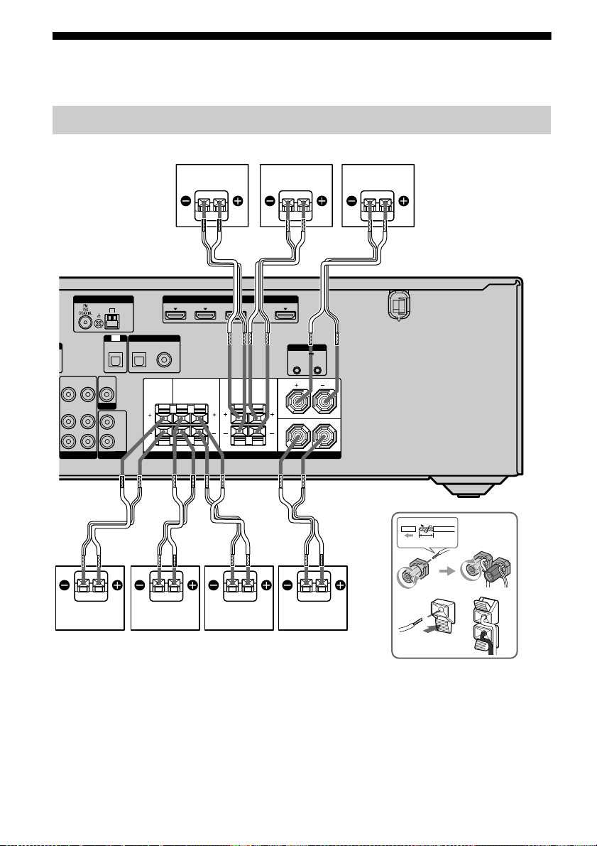
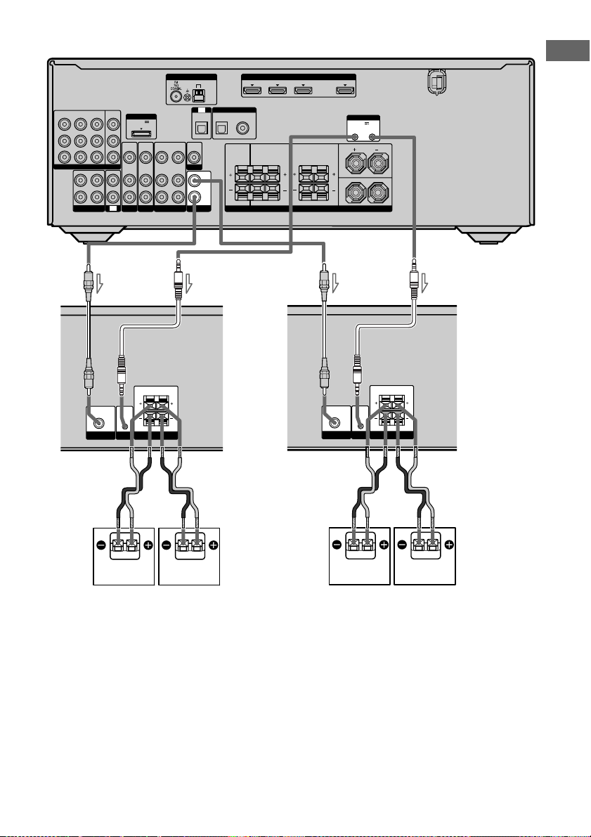
Connecting the subwoofers
The following illustration shows how to
connect to the subwoofers.
Note
To adjust the volume of all the speakers and the
subwoofers at the same time, press MASTER VOL
+/– on the remote. You can also use MASTER
VOLUME on the receiver.
HT-DDW7500
AM
TV
SAT
IN
Y
B
/
P
B
C
R
P
/
R
C
COMPONENT VIDEO
L
R
SA-CD/CD/CD-R
DVDINVIDEO 1INMONITOR
OUT
IN
OUT
DMPORT
DC5V
0.7A MAX
VIDEO
VIDEO
VIDEO
IN
OUT
IN
AUDIO
AUDIO
AUDIO
IN
OUT
IN
IN
TV
SAT
BD
VIDEO 1
DIGITAL
SATINDVD
IN
OPTICAL
OPTICAL COAXIAL
VIDEO
VIDEO
OUT
IN
MONITOR
AUDIO
IN
AUDIO
OUT
SUBWOOFER
A
AUDIO
IN
SYSTEM
SUBWOOFER
CONTROL
C
A Monaural audio cord (supplied)
B System control cable (supplied)
C Speaker cord (supplied)
a)
ASubwoofer
BSubwoofer
SAT IN
DVD IN BD IN OUT
(ASSIGNABLE)
IN
CENTER SURROUND BACK
R
L
B
SUBWOOFER ONLY FOR SS-WP7500
SUBWOOFER
IN
SPEAKER
HDMIANTENNA
SYSTEM CONTROL
DCSV
50mA MAX
OUT OUT
SURROUND
SPEAKERS
FRONT
L
LR
R
BA
a)
Use the red and black speaker cords to connect the
subwoofers.
Red wire is positive (+) in polarity and should be
connected to the positive (+) speaker terminal.
Connect black wire to the negative (–) speaker
terminal.
20
GB
HT-DDW8500
DVDINVIDEO 1INMONITOR
SAT
IN
Y
P
B
/
C
B
P
R
/
C
R
COMPONENT VIDEO
OUT
L
R
SA-CD/CD/CD-R
A
IN
AUDIO
IN
SUBWOOFER
OUT
IN
TV
SYSTEM
CONTROL
DMPORT
DC5V
0.7A MAX
VIDEO
VIDEO
IN
IN
AUDIO
AUDIO
IN
IN
SAT
BD
SUBWOOFER ONLY FOR SS-WP7500
IN
B
SUBWOOFER
SPEAKERS
VIDEO
OUT
AUDIO
OUT
VIDEO 1
HDMIANTENNA
DVD IN BD IN OUT
SURROUND
L
R
SPEAKERS
A
LR
AUDIO
IN
SUBWOOFER
SYSTEM CONTROL
DCSV
50mA MAX
OUT OUT
FRONT
L
R
IN
SYSTEM
CONTROL
B
SUBWOOFER ONLY FOR SS-WP7500
SUBWOOFER
SPEAKERS
DIGITAL
IN
OPTICAL COAXIAL
SATINDVD
SAT IN
(ASSIGNABLE)
IN
CENTER SURROUND BACK
AM
TV
OPTICAL
VIDEO
VIDEO
OUT
IN
MONITOR
AUDIO
IN
AUDIO
OUT
SUBWOOFER
Getting Started
C
BA
A Monaural audio cord (supplied)
B System control cable (supplied)
C Speaker cord (supplied)
a)
ASubwoofer
BSubwoofer
CSubwoofer
DSubwoofer
C
DC
a)
Use the red and black speaker cords to connect the
subwoofers.
Red wire is positive (+) in polarity and should be
connected to the positive (+) speaker terminal.
Connect black wire to the negative (–) speaker
terminal.
21
GB
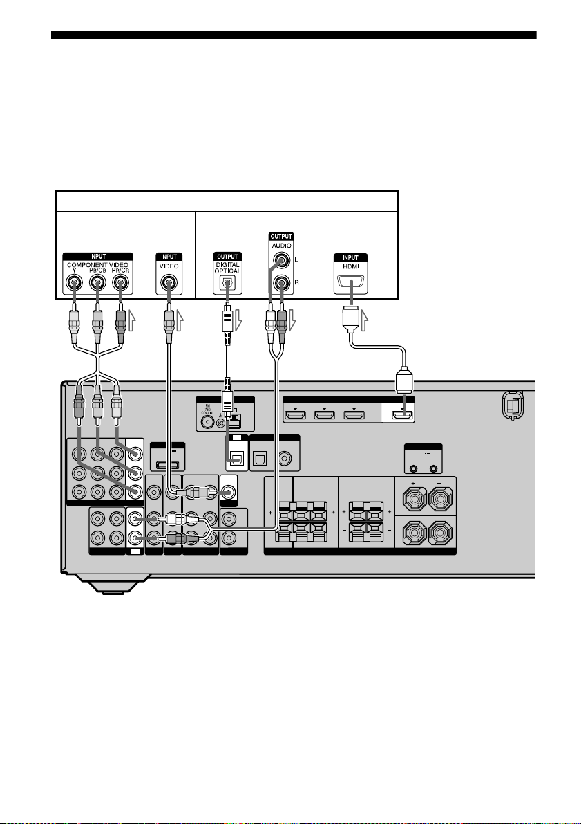
3: Connecting the TV
You can watch the selected input image when
you connect the HDMI OUT or MONITOR
OUT jack to a TV.
It is not necessary to connect all the cords.
Connect audio and video cords according to
the jacks of your components.
TV
SAT DVD VIDEO 1
Y
P
B
/
C
B
P
R
/
C
R
COMPONENT VIDEO
OUT
L
R
SA-CD/CD/CD-R
Video signals
A
MONITOR
OUT
IN
IN
IN
IN
TV
DMPORT
VIDEO
IN
AUDIO
IN
SAT
DC5V
0.7A MAX
VIDEO
AUDIO
BD
IN
IN
Audio signals
BCD
AM
TV
DIGITAL
SATINDVD
IN
OPTICAL
VIDEO
OUT
MONITOR
SUBWOOFER
AUDIO
OUT
OPTICAL COAXIAL
VIDEO
OUT
AUDIO
OUT
VIDEO 1
VIDEO
AUDIO
IN
IN
Before connecting the cords, be sure to
disconnect the AC power cord (mains lead).
Audio/video
signals
E
SAT ININDVD IN BD IN
(ASSIGNABLE)
IN
CENTER SURROUND BACK
L
R
HDMIANTENNA
SURROUND
SPEAKERS
OUT
SYSTEM CONTROL
DCSV
50mA MAX
OUT OUT
FRONT
L
LR
R
A Component video cord (not supplied)
B Video cord (not supplied)
C Optical digital cord (not supplied)
D Audio cord (not supplied)
E HDMI cable (not supplied)
We recommend that you use a Sony HDMI cable.
GB
22
Notes
G
• Be sure to turn on the receiver when the video and
audio signals of a playback component are being
output to a TV via the receiver. Unless the power is
turned on, neither video nor audio signals will be
transmitted.
• When connecting optical digital cords, insert the
plugs straight in until they click into place.
• Do not bend or tie optical digital cords.
Tips
• To output the sound of the TV from the speakers
connected to the receiver, be sure to
– connect the audio output jacks of the TV to the
TV IN jacks of the receiver.
– turn off the TV’s volume or activate the TV’s
muting function.
• All the digital audio jacks are compatible with
32 kHz, 44.1 kHz, 48 kHz, and 96 kHz sampling
frequencies.
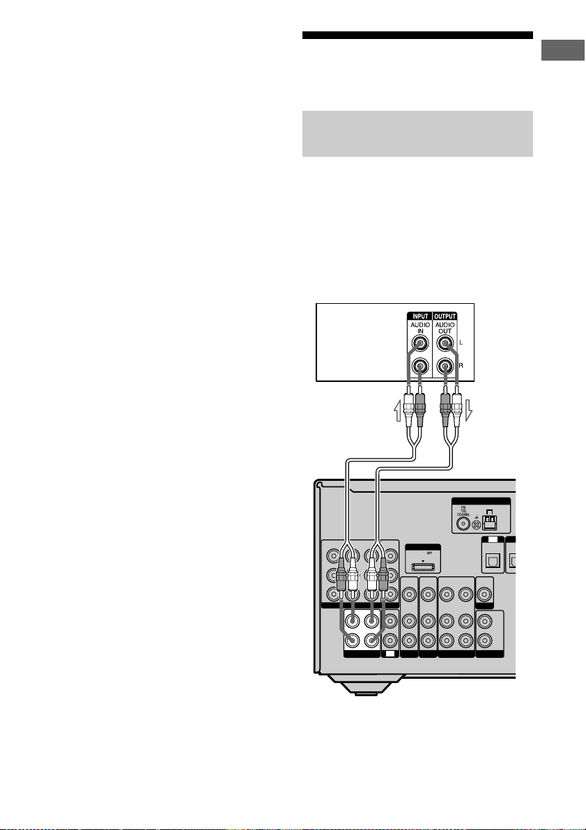
4a: Connecting the audio components
Connecting a Super Audio CD/
CD player or CD recorder
The following illustration shows how to
connect a Super Audio CD player, CD player
or CD recorder.
Before connecting the cords, be sure to
disconnect the AC power cord (mains lead).
After connecting your audio component,
proceed to “4b: Connecting the video
components” (page 24).
Super Audio CD
player/CD player/
CD recorder
A
Getting Started
ANTENNA
AM
TV
OPTICAL
VIDEO
OUT
MONITOR
SUBWOOFER
AUDIO
DI
IN
OPT
OUT
SAT
DVDINVIDEO 1INMONITOR
IN
Y
P
B
/
C
B
P
R
/
C
R
COMPONENT VIDEO
L
R
SA-CD/CD/CD-R
OUT
DMPORT
DC5V
0.7A MAX
VIDEO
VIDEO
VIDEO
VIDEO
IN
OUT
IN
IN
AUDIO
AUDIO
AUDIO
OUT
IN
AUDIO
IN
OUT
IN
IN
IN
TV
SAT
BD
VIDEO 1
A Audio cord (not supplied)
GB
23
4b: Connecting the video components
How to connect your
components
This section describes how to connect your
video components to this receiver. Before
you begin, refer to “Component to be
connected” below for the pages which
describe how to connect each component.
Before connecting the cords, be sure to
disconnect the AC power cord (mains lead).
After connecting all your components,
proceed to “5: Connecting the antennas
(aerials)” (page 31).
Component to be connected
Component Page
TV 22
With HDMI jack 26
DVD player/Blu-ray disc player 28
Satellite tuner/Set-top box 29
DVD recorder, VCR 30
Camcorder, video game, etc. 30
If you want to connect several
digital components, but
cannot find an unused input
See “Listening to digital sound from other
inputs (DIGITAL ASSIGN)” (page 70).
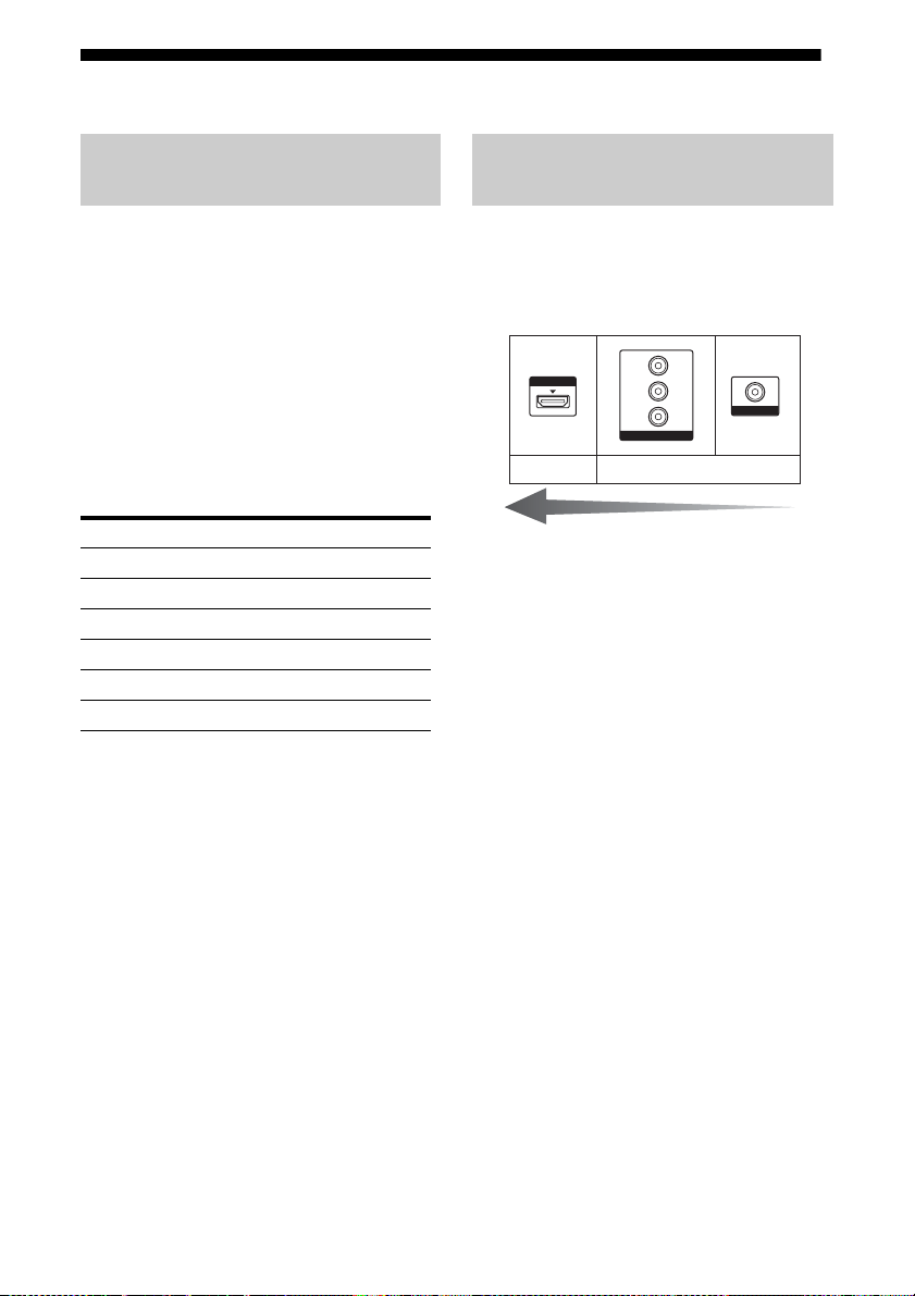
Video input/output jacks to be
connected
The image quality depends on the connecting
jack. Refer to the illustration that follows.
Select the connection according to the jacks
on your components.
HDMI
Digital Analog
High quality image
Note
Be sure to turn on the receiver when the video and
audio signals of a playback component are being
output to a TV via the receiver. Unless the power
is turned on, neither video nor audio signals will be
transmitted.
Y
P
B
/
C
B
P
R
/
C
R
COMPONENT VIDEO
VIDEO
24
GB

When you connect a DVD player
or DVD recorder
You can use the DVD input button on the
remote to control your DVD player or DVD
recorder. You may need to change the factory
setting of this button depending on the remote
supplied with this receiver. The factory setting
for the remote is shown in the table below:
Remote Factory setting
RM-AAU021 DVD player (Change the
factory setting if you connect
a DVD recorder)
RM-AAU023 DVD recorder (Change the
factory setting if you connect
a DVD player)
To change the factory setting of the DVD input
button on the remote, see “Changing button
assignments” (page 75).
Getting Started
25
GB
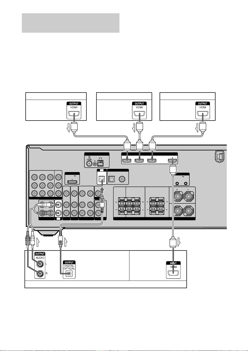
Connecting components with
HDMI jacks
HDMI is the abbreviated name for HighDefinition Multimedia Interface. It is an
interface which transmits video and audio
To enjoy TV multi channel
surround sound broadcasting
You can listen to TV multi channel surround
sound broadcasting from the speakers
connected to the receiver.
Connect the OPTICAL output jack of the TV
to the OPTICAL IN jack of the receiver.
signals in digital format.
Note
You can also rename the DVD input so that it can be
displayed on the receiver’s display. For details, see
“Naming inputs” (page 40).
Satellite tuner/Set-top box DVD player Blu-ray disc player
Audio/video
signals
Audio/video
signals
Audio/video
signals
AAA
ANTENNA
AM
TV
OPTICAL
VIDEO
OUT
MONITOR
SUBWOOFER
IN
OPTICAL COAXIAL
AUDIO
OUT
DIGITAL
SATINDVD
SAT
DVDINVIDEO 1INMONITOR
IN
Y
P
B
/
C
B
P
R
/
C
R
COMPONENT VIDEO
OUT
L
R
SA-CD/CD/CD-R
OUT
DMPORT
DC5V
0.7A MAX
VIDEO
VIDEO
VIDEO
VIDEO
IN
OUT
IN
IN
AUDIO
AUDIO
AUDIO
AUDIO
IN
OUT
IN
IN
IN
IN
TV
SAT
BD
VIDEO 1
Audio signals
TV, etc.
A HDMI cable (not supplied)
We recommend that you use a Sony HDMI cable.
B Optical digital cord (not supplied)*
C Audio cord (not supplied)*
* Connect at least one of the audio cords (B or C).
SAT IN DVD IN BD IN
(ASSIGNABLE)
IN
CENTER SURROUND BACK
L
R
Audio/video
signals
HDMI
SURROUND
SPEAKERS
OUT
SYSTEM CONTROL
DCSV
50mA MAX
OUT OUT
FRONT
L
LR
R
ABC
26
GB

HDMI features
• A digital audio signal transmitted by HDMI
can be output from the speakers connect to
this receiver. This signal supports Dolby
Digital, DTS, and Linear PCM.
• This receiver supports xvYCC transmission.
• This receiver supports the Control for HDMI
function. For details, see ““BRAVIA” Sync
Features” (page 64).
Notes on HDMI connections
• An audio signal input to the HDMI IN jack
is output from the speaker output jack and
HDMI OUT jack. It is not output from any
other audio jacks.
• Video signals input to the HDMI IN jack can
only be output from the HDMI OUT jack.
The video input signals cannot be output
from the VIDEO OUT jacks or MONITOR
OUT jacks.
• When you want to listen to the sound from
the TV speaker, set “AUDIO OUT” to
“TV+AMP” in the HDMI menu (page 45). If
you cannot play back multi channel
software, set to “AMP”. However, the sound
will not output from the TV speaker.
• The multi/stereo area audio signals of a
Super Audio CD are not output.
• Audio signals (sampling frequency, bit
length, etc.) transmitted from an HDMI jack
may be suppressed by the connected
component. Check the setup of the
connected component if an image is poor or
the sound does not come out of a component
connected via the HDMI cable.
• Sound may be interrupted when the
sampling frequency, the number of channels
or the audio format of the audio output
signals from the playback component is
switched.
• When the connected component is not
compatible with copyright protection
technology (HDCP), the image and/or the
sound from the HDMI OUT jack may be
distorted or may not be output.
In this case, check the specification of the
connected component.
• You can enjoy multi channel Linear PCM
only with an HDMI connection.
• Set the image resolution of the playback
component to 720p, 1080i or 1080p when
you output 96 kHz multi-channel sound over
an HDMI connection.
• You may need to make certain settings on the
image resolution of the player before you
can enjoy multi channel Linear PCM. Refer
to the operating instructions of the player.
• Refer to the operating instructions of each
component connected for details.
• We do not recommend using an HDMI-DVI
conversion cable. When you connect an
HDMI-DVI conversion cable to a DVI-D
component, the sound and/or the image may
not be output.
Getting Started
27
GB
 Loading...