

Sony HT-DDW7500 Quick Setup Manual
4-138-610-31(1)
L
R
DIGITAL
(ASSIGNABLE)
DC5V
0.7A MAX
DMPORT
SAT IN
SAT
IN
DVD IN BD IN OUT
AM
Y
P
B
/
C
B
COMPONENT VIDEO
OUT
IN
P
R
/
C
R
DVDINVIDEO 1INMONITOR
OUT
SA-CD/CD/CD-R
VIDEO 1
IN
TV
TV
AUDIO
IN
VIDEO
IN
SAT
AUDIO
OUT
AUDIO
OUT
VIDEO
OUT
VIDEO
OUT
IN
OPTICAL
AUDIO
IN
VIDEO
IN
SUBWOOFER
MONITOR
AUDIO
IN
VIDEO
IN
BD
SATINDVD
IN
DC5V
50mA MAX
OUT OUT
OPTICAL COAXIAL
CENTER SURROUND BACK
SURROUND
FRONT
L
L
R
R
LR
HDMIANTENNA
SPEAKERS
SYSTEM CONTROL
FRONT
L
R
SS-MSP7500
L
SS-MSP7500
R
SURROUND
LR
SPEAKERS
D
D
D
D
E
HT-DDW7500
Quick Setup Guide
Guide d’installation
(1)
Sony Corporation © 2009 Printed in Malaysia
1: Installing the speakers/
1: Installation des enceintes
2: Connecting the speakers and subwoofers/2: Raccordement
des enceintes et des caissons de graves
DVDINVIDEO 1INMONITOR
SAT
OUT
IN
DMPORT
DC5V
Y
0.7A MAX
B
/
P
C
B
VIDEO
VIDEO
IN
IN
P
R
/
C
R
COMPONENT VIDEO
AUDIO
AUDIO
OUT
IN
IN
IN
IN
L
R
TV
SAT
BD
SA-CD/CD/CD-R
DVDINVIDEO1INMONITOR
SAT
OUT
IN
DMPORT
DC5V
Y
0.7AMAX
B
/
P
C
B
VIDEO
VIDEO
IN
IN
P
R
/
C
R
COMPONENTVIDEO
AUDIO
AUDIO
OUT
IN
IN
IN
IN
L
R
TV
SAT
BD
SA-CD/CD/CD-R
HDMIANTENNA
SAT IN
DVD IN BD IN OUT
AM
(ASSIGNABLE)
TV
DIGITAL
SYSTEM CONTROL
DC5V
SATINDVD
50mA MAX
IN
IN
OUT OUT
OPTICAL
OPTICAL COAXIAL
VIDEO
VIDEO
VIDEO
OUT
AUDIO
OUT
VIDEO 1
FRONT
OUT
IN
SURROUND
L
CENTER SURROUND BACK
L
R
LR
MONITOR
AUDIO
IN
AUDIO
OUT
R
SUBWOOFER
SPEAKERS
CENTER SURROUND BACK
HDMIANTENNA
SATIN
DVDIN BDIN OUT
AM
(ASSIGNABLE)
TV
DIGITAL
SYSTEMCONTROL
DC5V
SATINDVD
50mAMAX
IN
IN
OUT OUT
OPTICAL
OPTICAL COAXIAL
VIDEO
VIDEO
VIDEO
FRONT
OUT
OUT
IN
SURROUND
L
CENTER SURROUNDBACK
L
R
LR
MONITOR
AUDIO
AUDIO
OUT
IN
AUDIO
OUT
R
SUBWOOFER
VIDEO1
SPEAKERS
CENTER SURROUND BACK
LR
SS-CNP7500
LR
A
SS-SRP7500 SS-SRP7500
A
A
HDMIANTENNA
SATIN
DVDIN BDIN OUT
AM
(ASSIGNABLE)
TV
DIGITAL
SAT
DVDINVIDEO1INMONITOR
IN
OUT
DMPORT
SYSTEMCONTROL
DC5V
Y
B
/
P
C
B
P
R
/
C
R
COMPONENTVIDEO
OUT
IN
IN
L
R
TV
SA-CD/CD/CD-R
DC5V
0.7AMAX
SATINDVD
50mAMAX
IN
IN
OUT OUT
OPTICAL
OPTICAL COAXIAL
VIDEO
VIDEO
VIDEO
VIDEO
VIDEO
FRONT
IN
OUT
OUT
IN
IN
SURROUND
L
CENTER SURROUNDBACK
L
R
LR
MONITOR
AUDIO
AUDIO
AUDIO
AUDIO
IN
OUT
IN
IN
AUDIO
OUT
R
SUBWOOFER
SAT
BD
VIDEO1
SPEAKERS
SS-SRP7500
SS-SRP7500
A
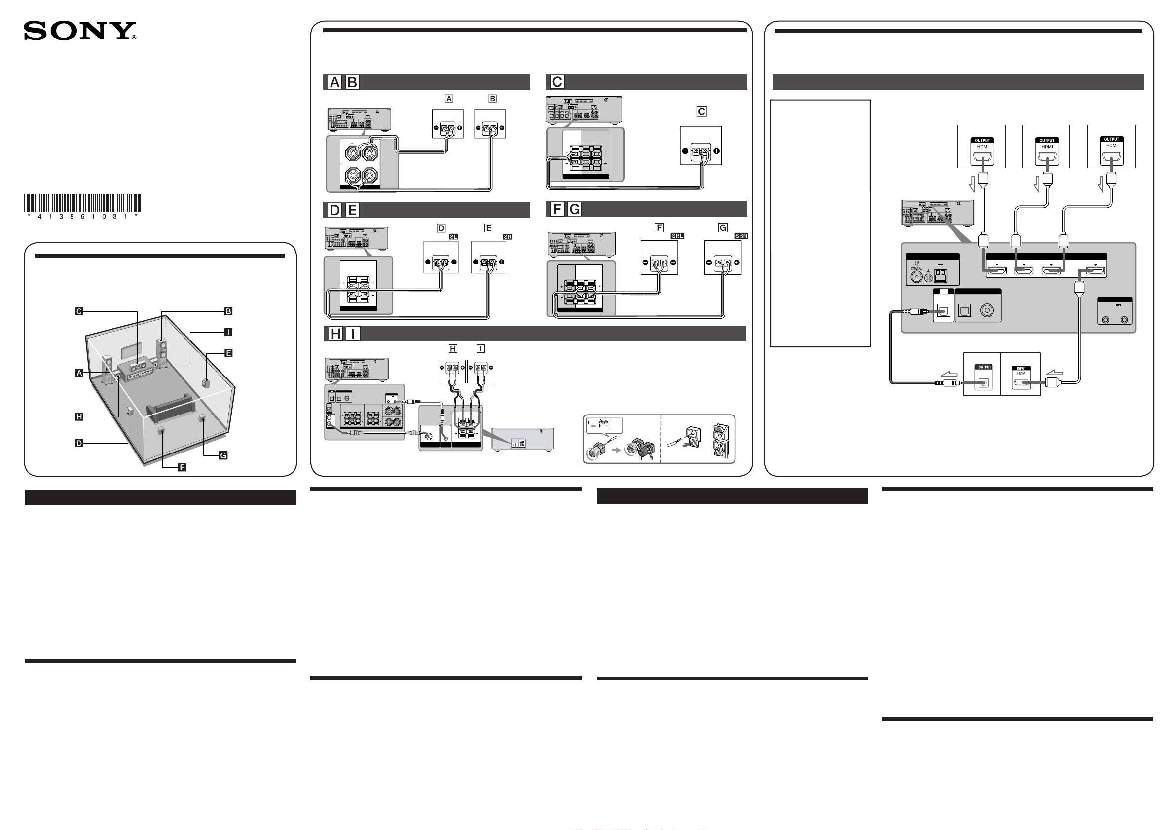
3: Connecting other components/ 3: Raccordement
d’autres éléments
Video components/Eléments vidéo
Note
Be sure to change the
factory setting of the
DVD input button on the
remote so that you can
use the button to control
your DVD player. For
details, see “Changing
button assignments” in the
operating instructions of the
receiver.
Remarque
Changez les réglages par
défaut de la touche d’entrée
DVD de la télécommande
afi n de pouvoir l’utiliser
pour commander votre
lecteur DVD. Pour obtenir
davantage d’informations,
reportez-vous à la section
« Modifi cation de l’affectation
des touches »
du mode
d’emploi de l’ampli-tuner.
Satellite tuner or Set-top box/
Tuner satellite ou Décodeur
HDMIANTENNA
SATIN
DVDIN BDIN OUT
AM
(ASSIGNABLE)
TV
DIGITAL
SAT
DVDINVIDEO1INMONITOR
IN
OUT
DMPORT
DC5V
Y
0.7AMAX
B
/
P
C
B
VIDEO
IN
P
R
/
C
R
COMPONENTVIDEO
AUDIO
OUT
IN
IN
IN
L
R
TV
SAT
SA-CD/CD/CD-R
SATINDVD
IN
OPTICAL
OPTICAL COAXIAL
VIDEO
VIDEO
VIDEO
VIDEO
OUT
OUT
IN
IN
CENTER SURROUNDBACK
MONITOR
AUDIO
AUDIO
AUDIO
OUT
IN
IN
AUDIO
OUT
SUBWOOFER
BD
VIDEO1
ANTENNA
IN
R
SURROUND
L
SPEAKERS
AM
TV
OPTICAL
SYSTEMCONTROL
DC5V
50mAMAX
OUT OUT
FRONT
L
LR
R
IN
(ASSIGNABLE)
DIGITAL
SATINDVD
OPTICAL COAXIAL
DVD player/
Lecteur DVD
HDMI
SATIN DVD IN OUT
IN
BD IN
Blu-ray disc player/
Lecteur de disques
Blu-ray
SYSTEM CONTROL
DC5V
50mA MAX
OUT OUT
1
/
?
English
This Quick Setup Guide describes how to connect a DVD player, Blu-ray disc player,
satellite tuner or set-top box, TV, speakers and subwoofers so that you can enjoy
multi channel surround sound. Refer to the operating instructions supplied with the
receiver for details.
The illustrations in the guide designate speakers as
A
Front speaker (left)
B
Front speaker (right)
C
Center speaker
D
Surround speaker (left)
E
Surround speaker (right)
F
Surround back speaker (left)
G
Surround back speaker (right)
H
Subwoofer
I
Subwoofer
A
through I.
1: Installing the speakers
The illustration above shows an example of seven speakers and two subwoofers
confi guration. Refer to the operating instructions supplied with the receiver.
About speaker placement
The front speakers, center speaker and subwoofers are magnetically shielded to allow
it to be installed near a TV set. However, as the surround and surround back speakers
are not magnetically shielded, we recommend that you place them slightly further
away from a TV set.
SS-WP7500
SUBWOOFERONLY FORSS-WP7500
IN
SYSTEM
CONTROL
SS-WP7500
SUBWOOFER
SPEAKERS
AUDIO
IN IN
SUBWOOFER SPEAKERS
SUBWOOFERONLYFORSS-WP7500
SUBWOOFER
SYSTEM
CONTROL
HDMIANTENNA
SATIN
DVDIN BDIN OUT
AM
(ASSIGNABLE)
TV
DIGITAL
DVDINVIDEO1INMONITOR
SAT
OUT
IN
DMPORT
SYSTEMCONTROL
DC5V
0.7AMAX
VIDEO
VIDEO
IN
IN
AUDIO
AUDIO
IN
IN
SAT
BD
DIGITAL
IN
OPTICAL COAXIAL
VIDEO
OUT
AUDIO
OUT
VIDEO1
SATINDVD
IN
IN
OPTICAL
OPTICAL COAXIAL
VIDEO
VIDEO
OUT
IN
CENTER SURROUNDBACK
R
MONITOR
AUDIO
IN
AUDIO
OUT
SUBWOOFER
(ASSIGNABLE)
SATINDVD
IN
CENTER SURROUND BACK
DC5V
50mAMAX
OUT OUT
FRONT
SURROUND
L
L
LR
R
SPEAKERS
C
SYSTEMCONTROL
DC5V
50mAMAX
OUT OUT
FRONT
SURROUND
L
L
R
LR
R
SPEAKERS
B
AUDIO
IN
SUBWOOFER
Y
B
/
P
C
B
P
R
/
C
R
COMPONENTVIDEO
OUT
IN
IN
L
R
TV
SA-CD/CD/CD-R
TV
OPTICAL
VIDEO
OUT
MONITOR
AUDIO
OUT
SUBWOOFER
Cords used for connection (supplied)/
Cordons utilisés pour le raccordement (fourni)
Speaker cord/Cordons d’enceintes
A
Monaural audio cord/Cordon audio mono
B
C
System control cable/Câble de commande système
2: Connecting the speakers and subwoofers
The illustrations above show how to connect the speakers. Before you connect the
speakers, check the speaker label on the rear panel of the speakers for the speaker
type.
For details, refer to the operating instructions supplied with the receiver.
About speaker cords
• Use the long speaker cords to connect the surround and surround back speakers and
the short speaker cords to connect the front speakers.
• Connect the cord attached with the “CENTER” labels to the center speaker.
• Use the red and black speaker cords to connect the subwoofers.
Red wire is positive (+) in polarity and should be connected to the positive (+)
speaker terminal.
Connect black wire to the negative (−) speaker terminal.
About speaker jacks
• Connect the
jack of the receiver.
#
jack to the 3 jack of the receiver and connect the # jack to the
3
• Refer to the illustration above for details of connecting speaker cords.
3: Connecting other components
This is an example of how to connect this receiver and your components. Refer to
step 3 and 4 of “Getting started” of the operating instructions supplied with this
receiver for details on other connections and other components.
10 mm
Cordons utilisés pour le raccordement (non fourni)
HDMI cable/Câble HDMI
D
Optical digital cord/Cordon numérique optique
E
Français
Cords used for connection (not supplied)/
Ce guide d’installation décrit comment raccorder un lecteur DVD, un lecteur de
disques Blu-ray, un tuner satellite ou un décodeur, un téléviseur, des enceintes et
un caisson de graves afi n que vous puissiez bénéfi cier du son surround multicanal.
Reportez-vous au mode d’emploi fourni avec l’ampli-tuner pour plus de détails.
A
Les illustrations du guide désignent les différentes enceintes, de
A
Enceinte avant (gauche)
B
Enceinte avant (droite)
C
Enceinte centrale
D
Enceinte surround (gauche)
E
Enceinte surround (droite)
F
Enceinte surround arrière (gauche)
G
Enceinte surround arrière (droite)
H
Caisson de graves
I
Caisson de graves
à I.
1: Installation des enceintes
Les illustrations ci-dessus montrent l’exemple d’une confi guration de système à sept
enceintes et deux caissons de graves. Reportez-vous au mode d’emploi fourni avec
l’ampli-tuner.
A propos de la position des enceintes
Les enceintes avant, l’enceinte centrale et le caisson de graves disposent d’un
blindage magnétique afi n de permettre leur installation à proximité d’un téléviseur.
Toutefois, étant donné que les enceintes surround et surround arrière ne disposent
pas d’un blindage magnétique, il est recommandé de les éloigner légèrement du
téléviseur.
DIGITAL
OPTICAL
TV/Téléviseur
2: Raccordement des enceintes et des caissons de
graves
Les illustrations ci-dessus indique comment raccorder les enceintes. Avant de
procéder au raccordement des enceintes, vérifi ez l’étiquette des enceintes située sur le
panneau arrière des enceintes pour en connaître le type.
Pour obtenir davantage d’informations, reportez-vous au mode d’emploi fourni avec
l’ampli-tuner.
A propos des cordons d’enceintes
• Utilisez les cordons d’enceintes longs pour raccorder les enceintes surround et
surround arrière, et les cordons d’enceintes courts pour raccorder les enceintes
avant.
• Branchez le cordon sur lequel est fi xée l’étiquette « CENTER » sur l’enceinte
centrale.
• Utilisez les cordons d’enceintes rouge et noir pour raccorder les caissons de graves.
Le fi l rouge présente une polarité positive (+) et doit être raccordé à la borne
positive (+) de l’enceinte. Raccordez le fi l noir à la borne négative (–) de l’enceinte.
A propos des prises d’enceinte
• Raccordez la prise
à la prise 3 de l’ampli-tuner et la prise # à la prise # de
3
l’ampli-tuner.
• Reportez-vous à l’illustration ci-dessus pour plus de détails sur le raccordement des
cordons d’enceinte.
3: Raccordement d’autres éléments
Ce guide donne un exemple de raccordement de cet ampli-tuner et de vos éléments.
Reportez-vous à l’étape 3 de la section « Préparatifs » du mode d’emploi fourni avec
cet ampli-tuner pour plus de détails sur le raccordement à d’autres éléments.
English
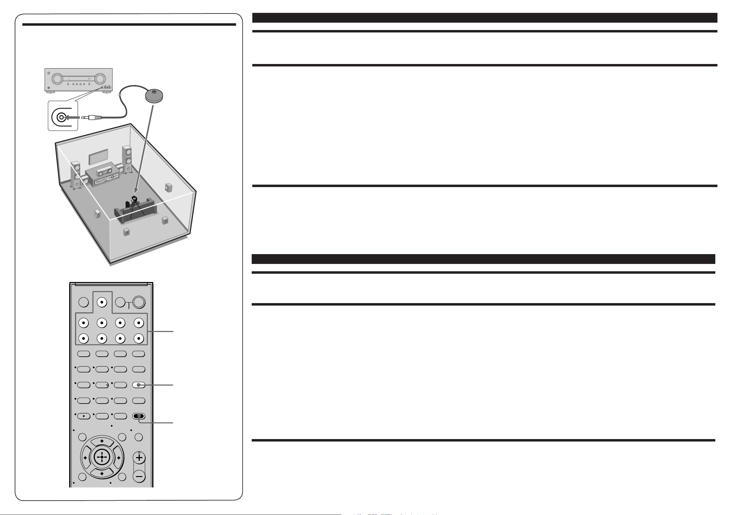
5: Calibrating the speaker settings automatically
5:
Calibrage automatique des réglages des enceintes
?/1
PHONES
AUTO CAL MIC
MOVIE
MUSIC
NIGHTMODE
A.F.D.
MASTERVOLUMEINPUTSELECTOR
Optimizer microphone (supplied)/
MULTISTEREOGAME
VIDEO2IN
AUTOCALMIC
VIDEO
LAUDIOR
1
/
?
Microphone optimiseur (fourni)
/
4: Connect all power cords last
Connect the AC power cord to a wall outlet.
Refer to “Connecting the AC power cord” in the operating instructions supplied with the receiver.
5: Calibrating the speaker settings automatically
You can set up the speakers to obtain the sound you want from all connected speakers automatically by using the Auto Calibration function. The Auto Calibration function will:
• Check the connection between each speaker and the receiver.
• Adjust the speaker level.
• Measure the distance of each speaker from your listening position.
1 Connect the supplied optimizer microphone to the AUTO CAL MIC jack on the receiver.
2 Set up the optimizer microphone.
Place the optimizer microphone at your listening position.You can also use a stool or tripod so that the optimizer microphone remains at the same height as your ears.
3 Press AMP MENU, then press AUTO CAL.
The Auto Calibration function starts.
For details on the Auto Calibration function, refer to step 7 of "Getting started" of the operating instructions supplied with this receiver.
Notes
• If there are any obstacles in the path between the optimizer microphone and the speakers, the calibration cannot be performed correctly. Remove any obstacles from the measurement area to avoid measurement error.
• The Auto Calibration function cannot detect the subwoofer. Therefore, all subwoofer settings will be maintained.
6: Setting up other components
You should set up each component so that the sound is output from the speakers correctly when you playback a connected component. Refer to the operating instructions supplied with each component.
Note
If no digital signal is input through the COAXIAL or OPTICAL jack on the receiver, “NO INPUT” appears on the display. This is not a malfunction.
After the setting
The receiver is now ready to use. Press the input button on the remote to select the component you want to play back. Refer to the operating instructions supplied with the receiver for details.
TV INPUT
DMPORT
SLEEP
VIDEO1 VIDEO2 BD DVD
SAT TV SA-CD/CD TUNER
2CH A.F.D. MOVIE MUSIC
?/1
TV
AV
SYSTEM STANDBY
?/1
?/1
THEATER
123
DVD/BD
9
MENU
AUTO CAL
D.TUNING
D.SKIP
AMP MENU
MUTING
46
5
78
0/10
MEMORY
ENTER
TOOLS/
OPTIONS
>10
CLEAR
DISPLAY
Input buttons/
Touches d’entrée
AUTO CAL
AMP MENU
Français
4: Raccordez tous les cordons d’alimentation en dernier lieu
Raccordez le cordon d’alimentation secteur à la prise murale.
Reportez-vous à la section « Raccordement du cordon d’alimentation secteur » dans le mode d’emploi fourni avec l’ampli-tuner.
5: Calibrage automatique des réglages des enceintes
Vous pouvez régler les enceintes afi n d’obtenir automatiquement le son souhaité pour toutes les enceintes raccordées en utilisant la fonction Auto Calibration. La fonction Auto Calibration :
• Vérifi ez le raccordement entre chaque enceinte et l’ampli-tuner.
• Ajustez le niveau des enceintes.
• Mesure la distance entre chaque enceinte et votre position d’écoute.
1 Raccordez le microphone optimiseur fourni à la prise AUTO CAL MIC de l’ampli-tuner.
2 Réglez le microphone optimiseur.
Placez le microphone optimiseur au niveau de votre position d’écoute. Vous pouvez également utiliser une chaise ou un trépied pour que le microphone optimiseur se
trouve au niveau de votre position d’écoute.
3 Appuyez sur AMP MENU, puis appuyez sur AUTO CAL.
La fonction Auto Calibration démarre.
Pour plus de détails sur la fonction Auto Calibration, reportez-vous à l’étape 7 de la section « Préparatifs » du mode d’emploi fourni avec cet ampli-tuner.
Remarques
• Si des obstacles se trouvent entre le microphone optimiseur et les enceintes, la calibration risque ne pas être effectuée correctement. Enlevez tous les obstacles se trouvant dans la zone de mesure, afi n d’éviter toute erreur de mesure.
• La fonction Auto Calibration ne peut pas détecter le caisson de graves. Par conséquent, tous les réglages du caisson de graves seront conservés.
O
RETURN/EXIT
TV VOL
MASTER VOL
MENU/HOME
6: Paramétrage d’autres éléments
Vous devez paramétrer chaque élément de sorte que le son soit émis correctement par les enceintes lorsque vous utilisez un élément raccordé. Reportez-vous au mode d’emploi fourni avec chaque élément.
Remarque
Si aucun signal n’est reçu via la prise COAXIAL ou OPTICAL, « NO INPUT » s’affi che. Ceci n’est pas un dysfonctionnement.
Après le paramétrage
L’ampli-tuner est maintenant prêt à l’emploi. Appuyez sur la touche d’entrée de la télécommande pour sélectionner l’élément sur lequel vous souhaitez effectuer une lecture. Reportez-vous au mode d’emploi
fourni avec l’ampli-tuner pour plus de détails.
 Loading...