

Sony HTC-V5550 Service Manual
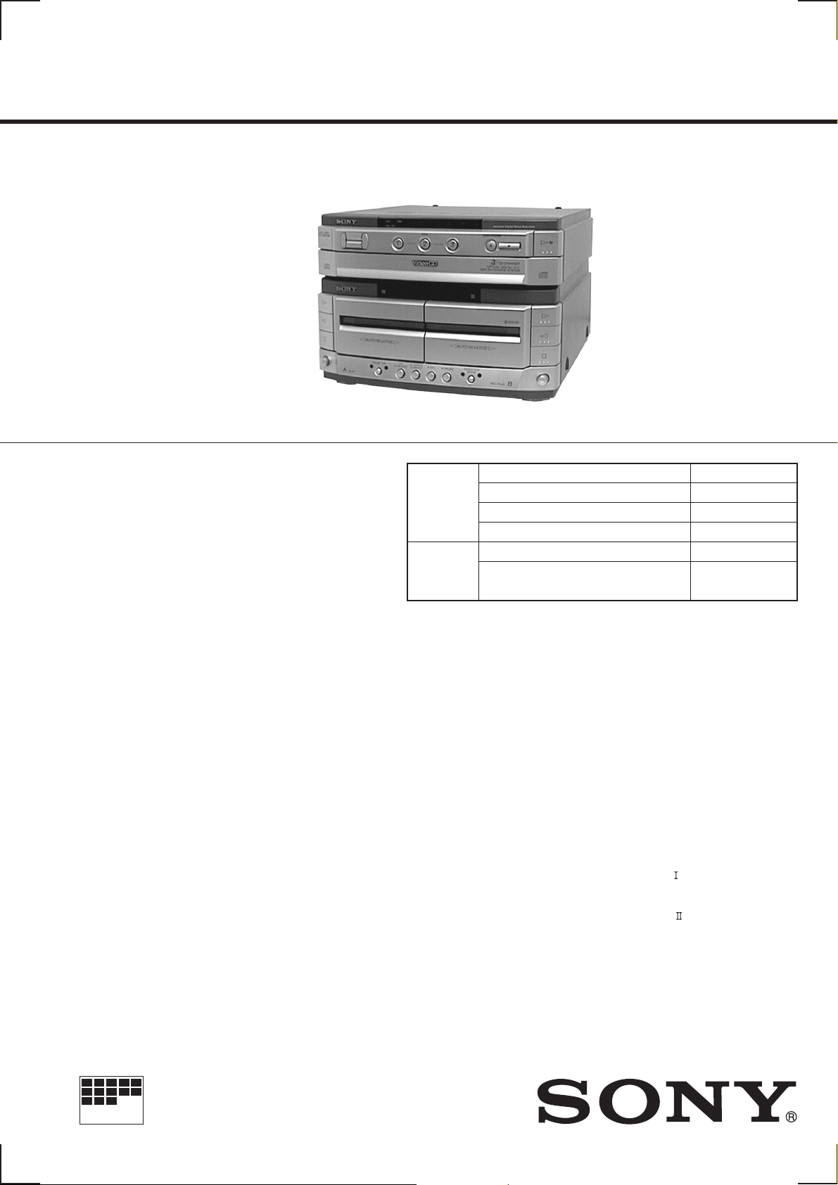
HTC-V5550
MICROFILM
SERVICE MANUAL
• This set is the deck and Video CD
section in MHC-V5550/V7770.
This stereo system is equipped with the Dolby Btype noise reduction system.
* Manufactured under license from Dolby
Laboratories Licensing Corporation.
DOLBY , the double-D symbol a and “PRO LOGIC”
are trademarks of Dolby Laboratories Licensing
Corporation.
CD CD Mechanism Type CDM38-5BD24
Section Base Unit Type BU-5BD24
Tape deck
Section Tape Transport Mechanism Type
E Model
Chinese Model
Model Name Using Similar Mechanism HCD-V717
Optical Pick-up Name KSS-213BA/F-NP
Model Name Using Similar Mechanism HTC-W555
TCM-230AWR2
TCM-230PWR2
SPECIFICATIONS
Video section
Inputs AV INPUT VIDEO (phono jack):
1Vp-p, 75 Ω
VIDEO IN (phono jack)
1Vp-p, 75 Ω
Outputs MONITOR OUT (phono jack):
1Vp-p, 75 Ω
VIDEO OUT (phono jack)
1Vp-p, 75 Ω
S-VIDEO (4-pin/mini-DIN jack):
Y: 1Vp-p, unbalanced, sync negative
C: 0.286Vp-p, load impedance 75 Ω
VIDEO CD/CD player section
System Compact disc, digital audio video system
Laser Semiconductor laser (λ=780nm)
Emission duradon: continuous
Laser output Max. 44.6µW*
*This output is the value measured at a
diatance of 200 mm from the objective
lens surface on the Optical Pick-up Block
with 7 mm aperture.
Frequency response 20 Hz – 20 kHz (±1 dB)
Wavelength 780 – 790 nm
Signal to noise ratio More than 90 dB
Dynamic range More than 90 dB
Video Color System format
NTSC, PAL
CD OPTICAL DIGITAL OUT
(Square optical connector jack, rear panel)
Wavelength 600 nm
Output Level –18 dBm
Tape player section
Recording system 4-track 2-channel stereo
Frequency response 40 – 13,000 Hz (±3 dB),
(DOLBY NR OFF) using Sony TYPE
cassette
40 – 14,000 Hz (±3 dB),
using Sony TYPE
cassette
Design and specifications are subject to change without notice.
COMPACT DISC DECK
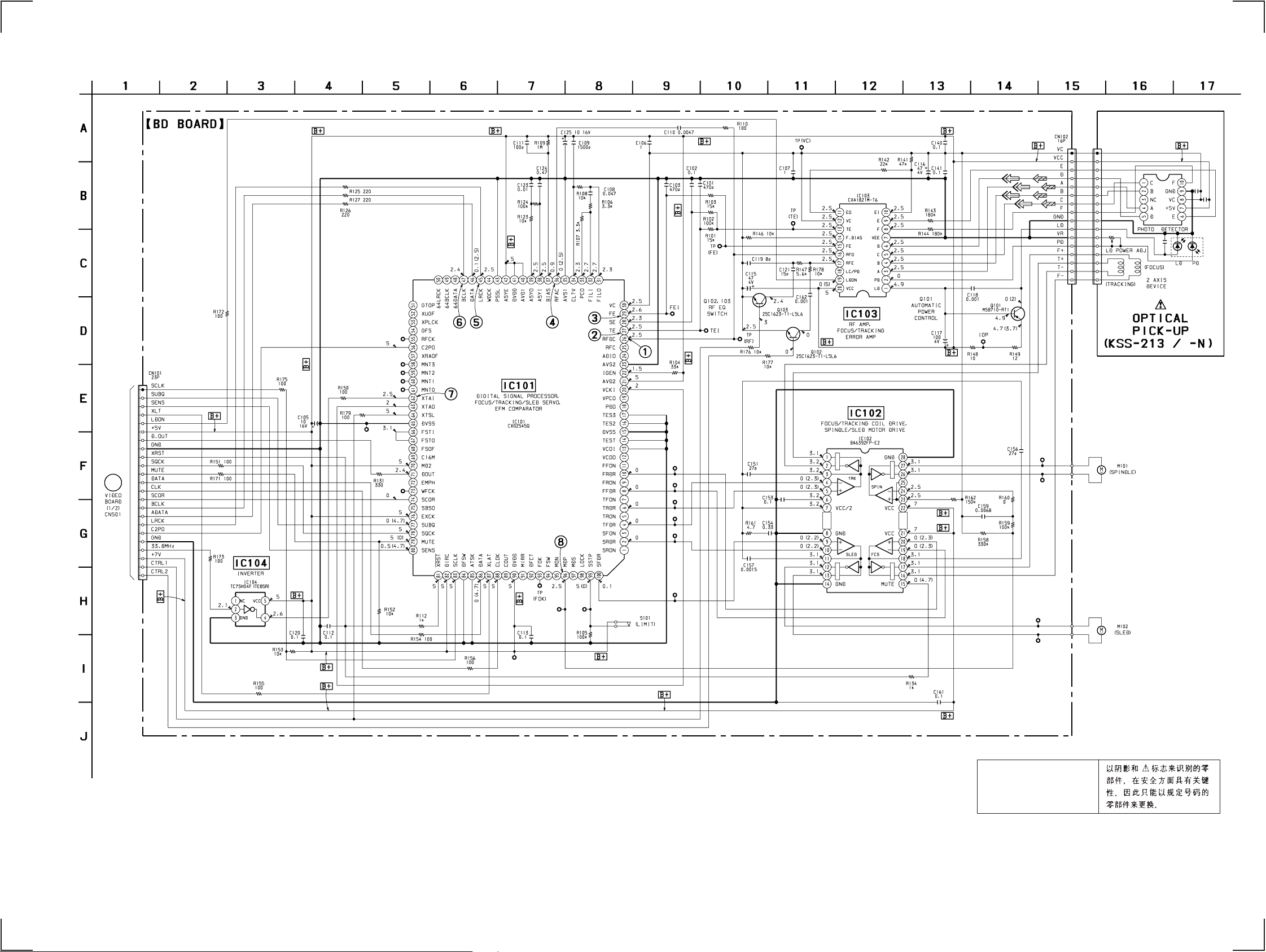
6-4. SCHEMATIC DIAGRAM — CD SECTION — • Refer to page 55 for Waveforms.
• Refer to page 58, 59 for IC Block Diagrams.
HTC-V5550
S
B
N
(Page 51)
16
The components identified by
mark ! or dotted line with mark
! are critical for safety.
Replace only with part number
specified.
— 27 — — 28 —
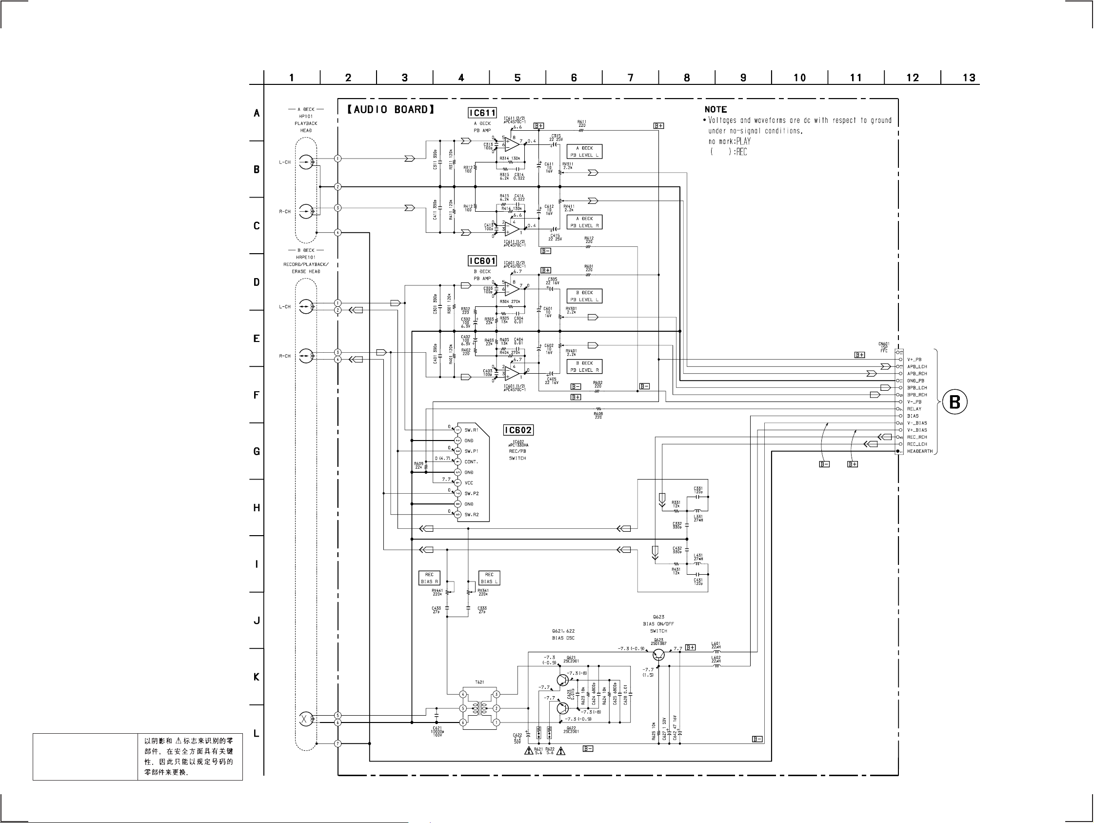
HTC-V5550
6-5. SCHEMATIC DIAGRAM — DECK SECTION —
• Refer to page 59 for IC Block Diagrams.
MAIN BOARD
CNS101
(Page 36)
The components identified by
mark ! or dotted line with mark
! are critical for safety.
Replace only with part number
specified.
16
— 29 — — 30 —
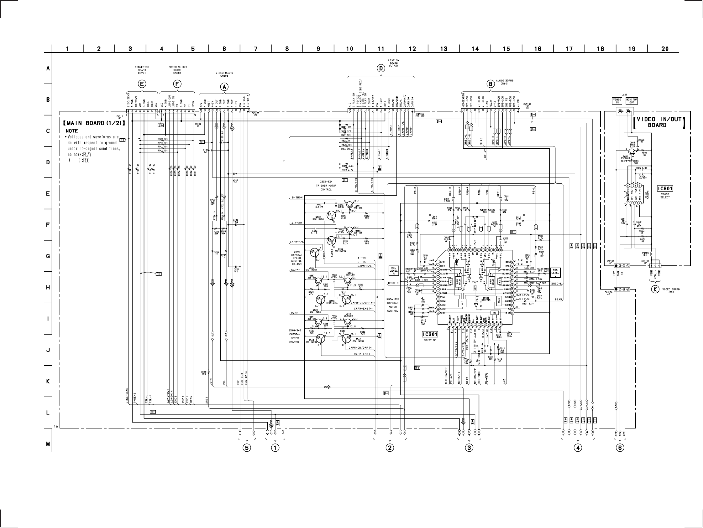
HTC-V5550
6-8. SCHEMATIC DIAGRAM — MAIN (1/2) SECTION —
(Page 46) (Page 46)
• Refer to page 59 for IC Block Diagrams.
(Page 51)
(Page 40)
(Page 30)
6.9
2.6
3.3
3.3
6.9
3.1
4.9
3.4
(Page 52)
— 35 — — 36 —
HTC-V5550
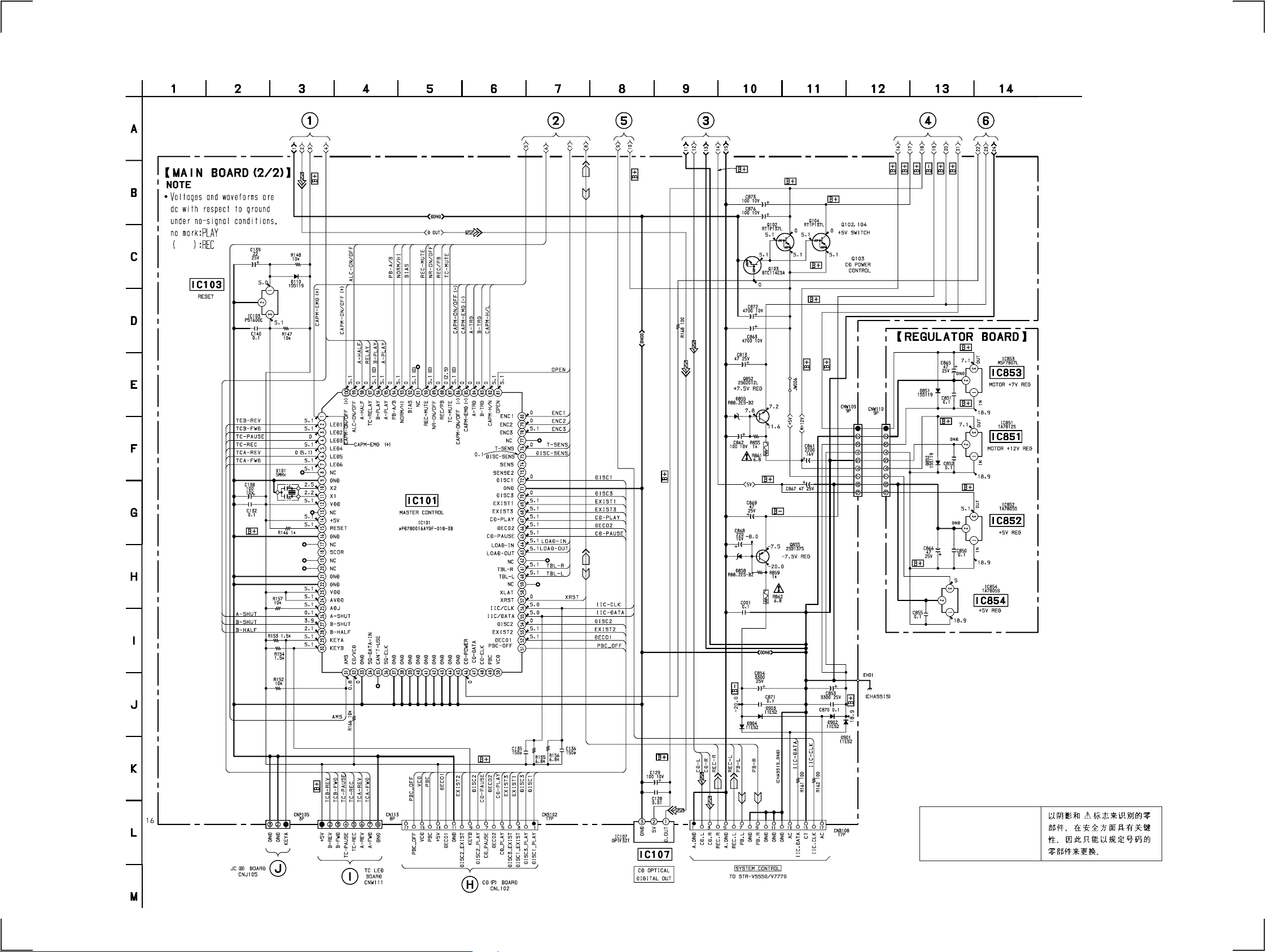
6-9. SCHEMATIC DIAGRAM — MAIN (2/2) SECTION — • Refer to page 33 for Printed Wiring Board.
• Refer to page 60 for IC Pin Function Description.
(Page 43)
(Page 43)
(Page 43)
— 37 — — 38 —
The components identified by
mark ! or dotted line with mark
! are critical for safety.
Replace only with part number
specified.
 Loading...