

Sony HT-1750DP User Manual
4-244-184-31(1)
Home Theater
System
Operating Instructions
Owner’s Record
The model and serial numbers are located at the rear of the unit. Record the serial
number in the space provided below. Refer to them whenever you call upon your Sony
dealer regarding this product.
Model No. Serial No.
HT-1750DP
© 2003 Sony Corporation
WARNING
To prevent fire or shock hazard, do not
expose the unit to rain or moisture.
To prevent fire, do not cover the ventilation of the
apparatus with newspapers, table-cloths, curtains, etc.
And don’t place lighted candles on the apparatus.
To prevent fire or shock hazard, do not place objects
filled with liquids, such as vases, on the apparatus.
Don’t throw away the battery with
general house waste, dispose of it
correctly as chemical waste.
Do not install the appliance in a confined space, such
as a bookcase or built-in cabinet.
– Reorient or relocate the receiving antenna.
– Increase the separation between the equipment and
receiver.
– Connect the equipment into an outlet on a circuit
different from that to which the receiver is
connected.
– Consult the dealer or an experienced radio/TV
technician for help.
CAUTION
You are cautioned that any changes or modification
not expressly approved in this manual could void
your authority to operate this equipment.
Note to CATV system installer:
This reminder is provided to call CATV system
installer’s attention to Article 820-40 of the NEC that
provides guidelines for proper grounding and, in
particular, specifies that the cable ground shall be
connected to the grounding system of the building, as
close to the point of cable entry as practical.
This symbol is intended to alert the
user to the presence of uninsulated
“dangerous voltage” within the
product’s enclosure that may be of
sufficient magnitude to constitute a
risk of electric shock to persons.
This symbol is intended to alert the
user to the presence of important
operating and maintenance (servicing)
instructions in the literature
accompanying the appliance.
WARNING
This equipment has been tested and found to comply
with the limits for a Class B digital device, pursuant
to Part 15 of the FCC Rules. These limits are
designed to provide reasonable protection against
harmful interference in a residential installation. This
equipment generates, uses, and can radiate radio
frequency energy and, if not installed and used in
accordance with the instructions, may cause harmful
interference to radio communications. However, there
is no guarantee that interference will not occur in a
particular installation. If this equipment does cause
harmful interference to radio or television reception,
which can be determined by turning the equipment
off and on, the user is encouraged to try to correct the
interference by one or more of the following
measures:
ENERGY STAR
mark.
As an ENERGY STAR® partner, Sony
Corporation has determined that this
product meets the ENERGY STAR
guidelines for energy efficiency.
This receiver incorporates Dolby* Digital and Pro
Logic Surround and the DTS** Digital Surround
System.
* Manufactured under license from Dolby
Laboratories.
“Dolby”, “Pro Logic” and the double-D symbol are
trademarks of Dolby Laboratories.
** “DTS” and “DTS Digital Surround” are registered
trademarks of Digital Theater Systems, Inc.
®
is a U.S. registered
®
US
2

Table of Contents
List of Button Locations and
Reference Pages
Main unit ............................................... 5
Hooking Up the Components
Required cords ....................................... 6
Antenna hookups ................................... 7
Audio component hookups .................... 8
Video component hookups .................... 9
Digital component hookups ................. 10
Other hookups ..................................... 11
Hooking Up and Setting Up
the Speaker System
Speaker system hookups ..................... 12
Performing initial setup operations ..... 14
Multi channel surround setup .............. 14
Checking the connections .................... 19
Basic Operations
Selecting the component ..................... 20
Changing the display ........................... 21
Enjoying Surround Sound
Using only the front speakers
(2 Channel Stereo) ........................ 22
Enjoying higher fidelity sound ............ 22
Selecting a sound field ........................ 23
Understanding the multi channel
surround displays .......................... 25
Customizing sound fields .................... 26
Receiving Broadcasts
Direct tuning ........................................ 28
Automatic tuning ................................. 29
Preset tuning ........................................ 29
Other Operations
Naming preset stations and program
sources ........................................... 31
Recording ............................................ 31
Using the Sleep Timer ......................... 32
Adjustments using the SET UP
menu .............................................. 32
Changing the command mode of the
receiver .......................................... 33
Operations Using the Remote
RM-PP412
Before you use your remote ................ 34
Remote button description ................... 34
Selecting the command mode of the
remote ............................................ 37
Programming the remote ..................... 38
Additional Information
Precautions .......................................... 41
Troubleshooting ................................... 41
Specifications ...................................... 44
Tables of settings using the MAIN
MENU button ................................ 47
Adjustable parameters for each sound
field ................................... back page
US
3

About This Manual
Note for the supplied remote
The HT-1750DP consists of:
– Receiver STR-K750P
– Speaker system
• Front/surround speakers SS-MSP75
• Center speaker SS-CNP75
• Sub woofer SA-WMSP75
– DVD player DVP-NS725P
Tip
The instructions in this manual describe the controls
on the receiver. You can also use the controls on the
supplied remote if they have the same or similar
names as those on the receiver. For details on the use
of your remote, see pages 34 – 40. For details on the
use of your DVD player, refer to the separate
operating instructions supplied with the DVD player.
RM-PP412
The VIDEO3, TV/SAT, PHONO, AUX,
MULTI CH, SOURCE, DIRECT, AAC
BI-LING, SB DECODING, 12 and ON
SCREEN buttons on the remote are not
available.
US
4
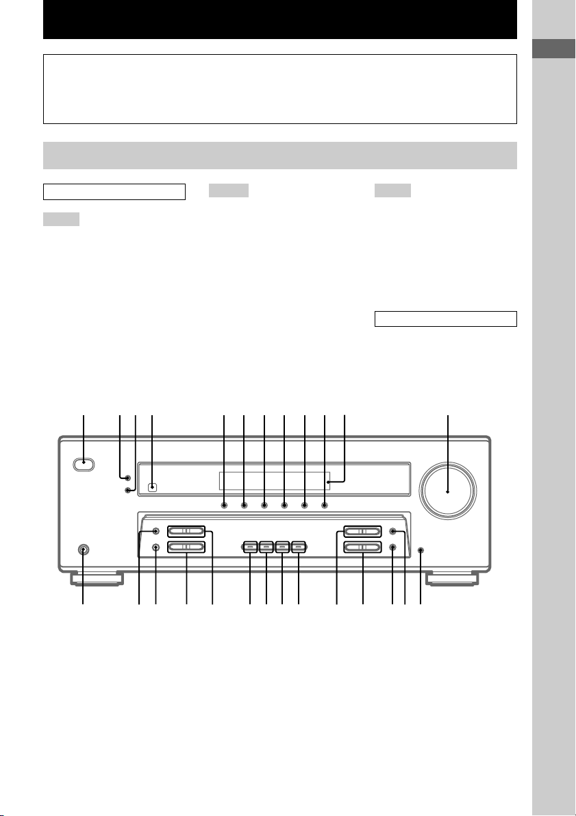
List of Button Locations and Reference Pages
How to use this page
Use this page to find the location of buttons that
are mentioned in the text.
Main unit
ALPHABETICAL ORDER
A – L
A.F.D. (button/indicator) w;
(22– 24)
CD 9 (20)
DIMMER 3 (21)
DISPLAY 2 (21, 43)
Display qa (21)
DVD 7 (20)
ENTER qg (31, 33)
FM MODE wf (28)
INPUT MODE qd (20)
IR (receptor) 4 (34, 43)
1784 0 qa qs523
M – O
MAIN MENU qf (15, 26, 27, 31,
32, 47)
MASTER VOLUME qs (18, 20,
41)
MD/TAPE 8 (20)
MEMORY wg (29)
MENU +/– qh (15, 26, 27, 31, 32,
47)
MENU </> qj (15, 26, 27, 31, 32,
47)
MOVIE (button/indicator) ql (23,
42)
MUSIC (button/indicator) qk (23,
24, 42)
6
Illustration number
r
DISPLAY 2 (21, 43)
Name of button/part Reference page
RR
P – Z
PHONES (jack) wh (20, 25, 42)
PRESET TUNING +/– ws (29,
30, 45)
TUNER FM/AM q; (20, 29, 30,
31)
TUNING +/– wd (29)
VIDEO 1 5 (20)
VIDEO 2 6 (20)
NUMBERS AND SYMBOLS
2CH (button/indicator) wa (22,
24, 27)
`/1 (power) 1 (14, 19, 27, 33,
45)
9
List of Button Locations and Reference Pages
?/1
g
qdqfqgqhqjqkqlw;wawswdwg wfwh
US
5
Hooking Up the Components
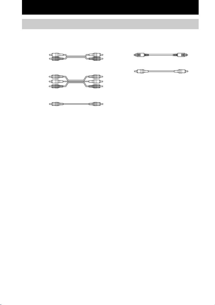
Required cords
The following optional connection cords A – E are required when you hook up the components
(pages 8 – 10).
A Audio cord (not supplied)
White (L)
Red (R)
B Audio/video cord (not supplied)
Yellow (video)
White (L/audio)
Red (R/audio)
C Video cord (not supplied)
Yellow
Before you get started
• Turn off the power to all components before making any connections.
• Do not connect the AC power cord until all of the connections are completed.
• Be sure to make connections firmly to avoid hum and noise.
• When connecting an audio/video cord, be sure to match the color-coded pins to the appropriate jacks on
the components: yellow (video) to yellow; white (left, audio) to white; and red (right, audio) to red.
• When you connect optical digital cords, insert the cord plugs straight in until they click into place.
• Do not bend or tie the optical digital cord.
D Optical digital cord (not supplied)
E Coaxial digital cord (supplied)
Orange
US
6
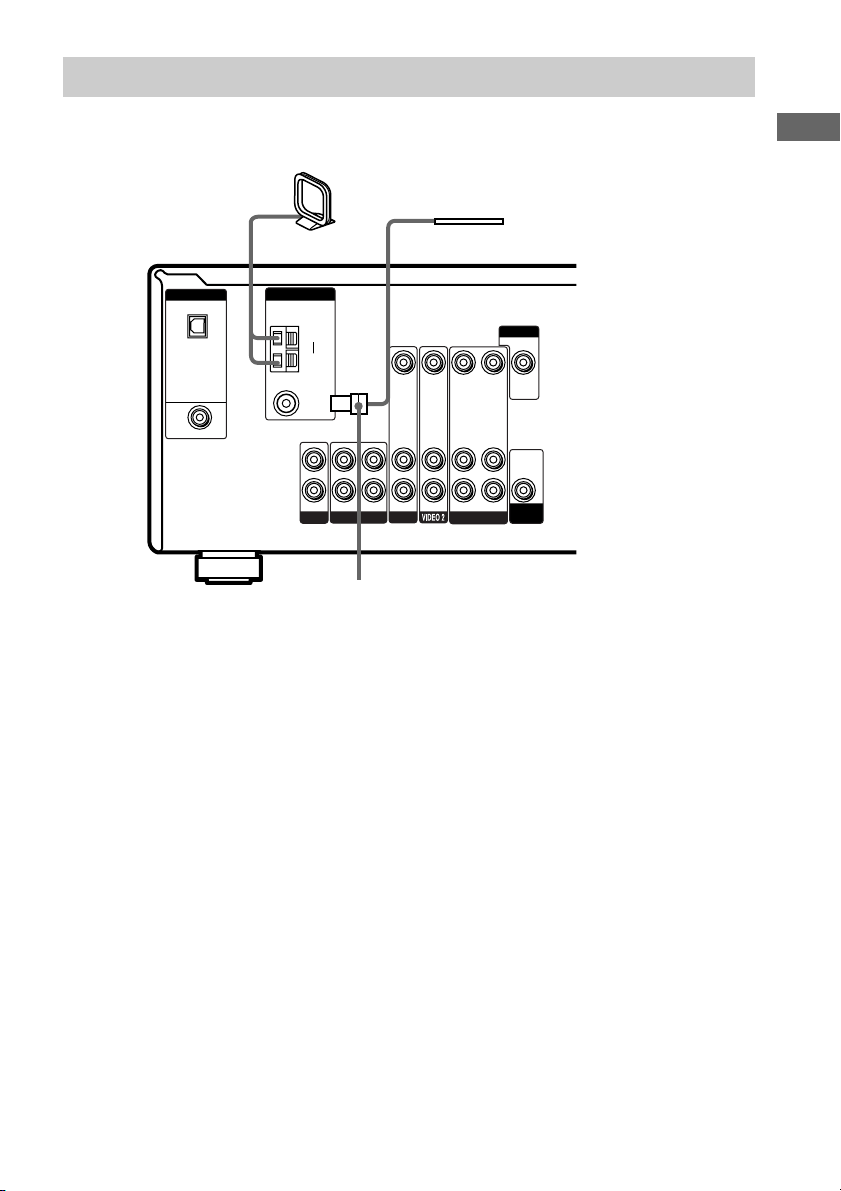
Antenna hookups
AM loop antenna
(supplied)
FM wire antenna
(supplied)
DIGITAL
OPTICAL
VIDEO 2
IN
DVD IN
COAXIAL
ANTENNA
AM
75Ω
COAXIAL
L
R
CD
y
FM
IN OUT
VIDEO IN VIDEO IN
AUDIO IN AUDIO IN
IN
DVDMD/TAPE
*
* The shape of the connector varies depending on the area code.
Notes on antenna hookups
• To prevent noise pickup, keep the AM loop
antenna away from the receiver and other
components.
• Be sure to fully extend the FM wire antenna.
• After connecting the FM wire antenna, keep it
as horizontal as possible.
MONITOR
VIDEO OUT VIDEO IN
AUDIO OUT AUDIO IN
VIDEO 1
VIDEO OUT
AUDIO
OUT
SUB
WOOFER
Hooking Up the Components
US
7
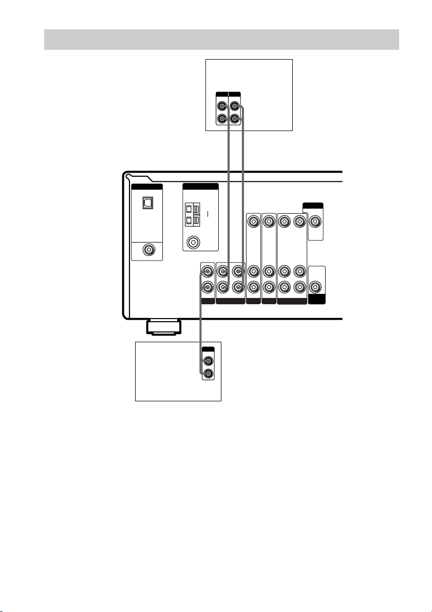
Audio component hookups
MD or Tape deck
INPUT OUTPUT
LINE
LINE
L
R
AA
ç
INOUT
ç
DIGITAL
OPTICAL
VIDEO 2
IN
DVD IN
COAXIAL
ANTENNA
CD player
COAXIAL
L
R
A
OUTPUT
AM
y
FM
75Ω
IN OUT
CD
LINE
L
R
VIDEO IN VIDEO IN
AUDIO IN AUDIO IN
IN
DVDMD/TAPE
VIDEO 2
VIDEO OUT VIDEO IN
AUDIO OUT AUDIO IN
VIDEO 1
MONITOR
VIDEO OUT
AUDIO
OUT
SUB
WOOFER
US
8
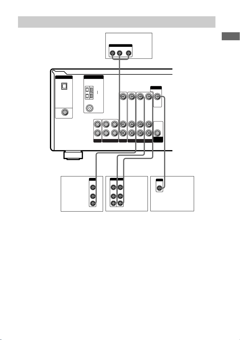
Video component hookups
DIGITAL
OPTICAL
VIDEO 2
IN
DVD IN
COAXIAL
Satellite
tuner or
VCR
ANTENNA
COAXIAL
L
R
CD
Ç
IN
B
OUTPUT
VIDEO
OUT
AUDIO
OUT
AM
y
FM
75Ω
IN OUT
L
R
DVD player
OUTPUT
AUDIO OUT VIDEO
L
OUT
R
B
VIDEO IN VIDEO IN
AUDIO IN AUDIO IN
IN
Ç
BB
OUTPUTINPUT
VIDEO
VIDEO
OUT
IN
AUDIO
AUDIO
OUT
IN
VIDEO OUT VIDEO IN
AUDIO OUT AUDIO IN
VIDEO 2
DVDMD/TAPE
Ç
INOUT
L
R
VCR
VIDEO 1
MONITOR
VIDEO OUT
AUDIO
OUT
SUB
WOOFER
INPUT
VIDEO
IN
TV monitor
Hooking Up the Components
C
Note on video component
hookups
You can connect your TV’s audio output jacks
to the VIDEO 2 AUDIO IN jacks on the
receiver and apply sound effects to the audio
from the TV. In this case, do not connect the
TV’s video output jack to the VIDEO 2
VIDEO IN jack on the receiver. If you are
connecting a separate satellite tuner, connect
both the audio and video output jacks to the
receiver as shown above.
US
9
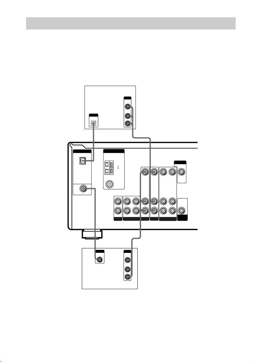
Digital component hookups
Connect the digital output jacks of your DVD player and satellite tuner (etc.) to the receiver’s digital
input jacks to bring the multi channel surround sound of a movie theater into your home. To fully
enjoy multi channel surround sound, five speakers (two front speakers, two surround speakers, and a
center speaker) and a sub woofer are required.
Note
All the OPTICAL and COAXIAL jacks are compatible with 96 kHz, 48 kHz, 44.1 kHz and 32 kHz sampling
frequencies.
Satellite tuner
or DVD player*
DIGITAL
OPTICAL
VIDEO 2
IN
DVD IN
COAXIAL
DVD player
OUTPUT
DIGITAL
OPTICAL
(etc.)*
E
OUTPUT
DIGITAL
COAXIAL
ANTENNA
AM
75Ω
COAXIAL
L
R
CD
OUTPUT
VIDEO
AUDIO
y
FM
IN OUT
OUTPUT
VIDEO
AUDIO
OUT
OUT
L
R
BD
VIDEO IN VIDEO IN VIDEO OUT VIDEO IN
AUDIO IN AUDIO IN
IN
DVDMD/TAPE
B
OUT
OUT
L
R
VIDEO 2
AUDIO OUT AUDIO IN
VIDEO 1
MONITOR
VIDEO OUT
AUDIO
OUT
SUB
WOOFER
* Make either coaxial or optical connections. We recommend making coaxial connections instead of optical
connections.
US
10
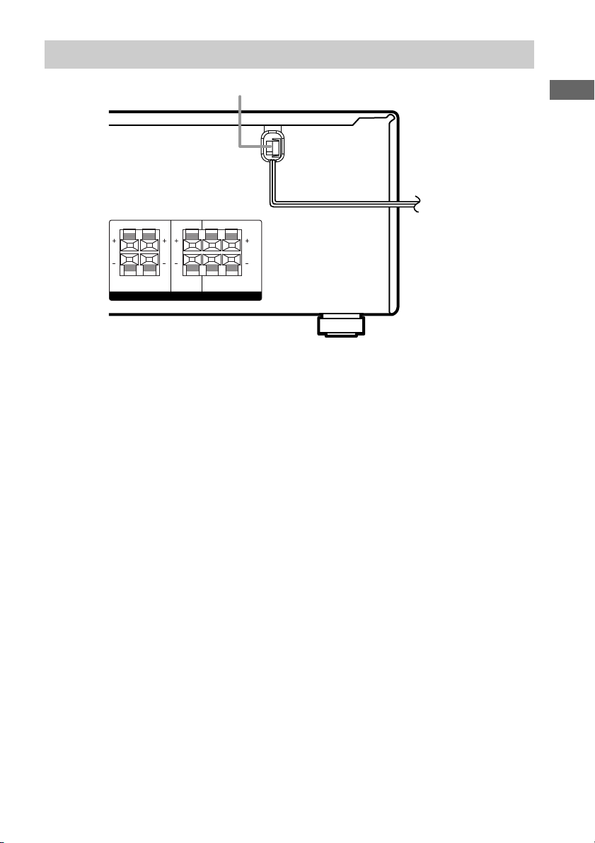
Other hookups
RRL
AC power cord
RRL
To a wall outlet
b
Hooking Up the Components
L
FRONT CENTER SURROUND
SPEAKERS
IMPEDANCE USE 8 – 16Ω
L
Connecting the AC power
cord
Before connecting the AC power cord of this
receiver to a wall outlet, connect the speaker
system to the receiver (page 12).
Connect the AC power cord(s) of your audio/
video components to a wall outlet.
11
US
Hooking Up and Setting Up the Speaker System
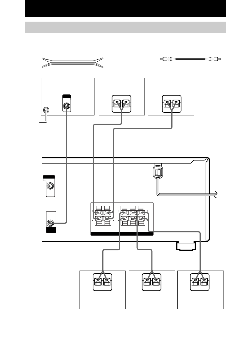
Speaker system hookups
Required cords
A Speaker cords (supplied)
(+)
(–)
B Monaural audio cord (supplied)
Black
Active sub woofer
b
To a wall outlet
(Switch the power
(POWER) to off
before connecting
the power cord.)
MONITOR
VIDEO OUT
AUDIO
OUT
SUB
WOOFER
INPUT
Front speaker (L)Front speaker (R)
Ee
B
RRL
FRONT CENTER SURROUND
SPEAKERS
L
A
RRL
L
IMPEDANCE USE 8 – 16Ω
E
e
A
12
US
A
E
Center speaker Surround speaker
e
Surround speaker
E
(R)
A
e
A
E
(L)
e
Tip
To prevent speaker vibration or movement while
listening, attach the supplied foot pads at the bottom
of the speakers.
Notes
• Connect the long speaker connecting cords to the
surround speaker terminals and the short speaker
connecting cords to the front and center speaker
terminals.
• Twist the stripped ends of the speaker cords about
2/3 inch. Be sure to match the speaker cord to the
appropriate terminal on the components: + to + and
– to –. If the cords are reversed, the sound will be
distorted and will lack bass.
• If you use speakers with low maximum input rating,
adjust the volume carefully to avoid excessive
output on the speakers.
To avoid short-circuiting the
speakers
Short-circuiting of the speakers may damage
the receiver. To prevent this, make sure to take
the following precautions when connecting the
speakers.
Make sure the stripped ends of each
speaker cord does not touch another
speaker terminal, the stripped end of
another speaker cord, or the metal parts of
the receiver.
Examples of poor conditions of the
speaker cord
Hooking Up and Setting Up the Speaker System
Stripped cords are touching each other
due to excessive removal of insulation.
Stripped cords are not fully attached and
are touching the rear panel of the receiver.
After connecting all the components,
speakers, and AC power cord, output
a test tone to check that all the
speakers are connected correctly.
For details on outputting a test tone,
see page 18.
If no sound is heard from a speaker while
outputting a test tone or a test tone is output
from a speaker other than the one whose name
is currently displayed on the receiver, the
speaker may be short-circuited. If this happens,
check the speaker connection again.
To avoid damaging your
speakers
Make sure that you turn down the volume
before you turn off the receiver. When you turn
on the receiver, the volume remains at the level
you turn off the receiver.
Stripped speaker cord is touching another
speaker terminal.
13
US
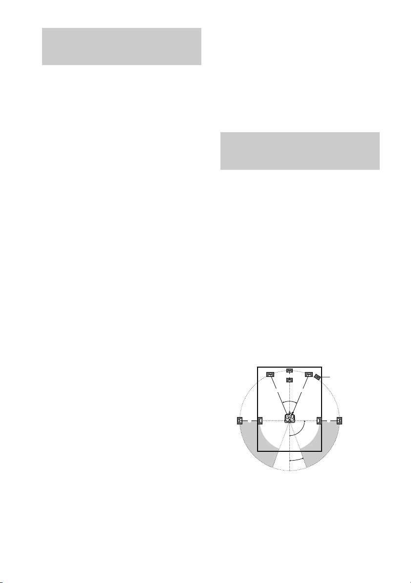
45°
90°
20°
B
CC
AA
Performing initial setup
operations
Once you have hooked up the speakers and
turned on the power, clear the receiver’s
memory. Then specify the speaker parameters
(size, position, etc.) and perform any other
initial setup operations necessary for your
system.
Tip
To check the audio output during settings (to set up
while outputting the sound), check the connection
(page 19).
Clearing the receiver’s
memory
Before using your receiver for the first time, or
when you want to clear the receiver’s memory,
do the following.
1 Turn off the receiver.
2 Hold down ?/1 for 5 seconds.
“INITIAL” appears in the display.
The following are reset to their factory
settings.
• All settings in the SET UP, LEVEL and
TONE menus.
• The sound field memorized for each
function and preset station.
• All sound field parameters.
• All preset stations.
• All index names of input selectors and
preset stations.
• The master volume is set to “VOL
MIN”.
Performing initial setup
operations
Before using your receiver for the first time,
adjust SET UP parameters so that the receiver
correspond to your system. For the adjustable
parameters, see the table on page 47. See pages
14–18 for speaker settings and pages 32–33 for
other settings.
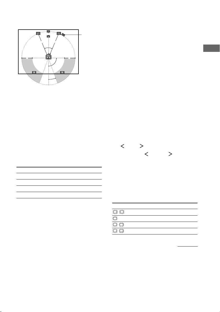
Multi channel surround
setup
For the best possible surround sound, all
speakers should be the same distance from the
listening position (A).
However, the receiver lets you place the center
speaker up to 5 feet closer (B) and the
surround speakers up to 15 feet closer (C) to
the listening position.
The front speakers can be placed from 3 to 23
feet from the listening position (A).
You can place the surround speakers either
behind you or to the side, depending on the
shape of your room (etc.). However, we
recommend that you place the surround
speakers behind you.
When placing surround speakers to your side
(long room)
Sub woofer
US
14
When placing surround speakers behind you
Note
Do not place the center speaker further away from the
listening position than the front speakers.
(wide room)
B
AA
45°
90°
20°
Sub woofer
CC
Normal Speaker and Micro
Satellite Speaker
For HT-1750DP, the speaker size and the sub
woofer selection has been preset to “MICRO
SP.” (Micro Satellite Speaker) according to the
supplied speaker system.
When you select “MICRO SP.”, the speaker
size and sub woofer selection has been
configurated as follows:
Speaker Settings
FRONT SMALL
CENTER SMALL
SURROUND SMALL
SUB WOOFER YES
You cannot change the configuration if you
select “MICRO SP.”.
If you change the speaker system, select
“NORM. SP.”. You can adjust the speaker size
and sub woofer selection when you select
“NORM. SP.” (page 17).
To select “NORM. SP.”, turn off the power,
then turn on again while pressing MAIN
MENU. (To reset to “MICRO SP.”, do the
same procedure.)
Tip
The setting for Micro Satellite Speaker (MICRO SP.)
has been programmed to optimize the sound balance.
If you use Sony’s Micro Satellite Speakers, select
“MICRO SP.”.
Caution
When you use Micro Satellite Speakers and the
speaker size is set to “LARGE”, you may not obtain
the correct soundstage. The speaker may also be
damaged at high volume position.
Specifying the speaker
parameters
1 Press MAIN MENU repeatedly to select
“ SET UP ”.
2 Press MENU or MENU to select
the parameter you want to adjust.
3 Press MENU + or MENU – to select the
setting you want.
The setting is entered automatically.
4 Repeat steps 2 and 3 until you have set
all of the parameters that follow.
Initial settings
Parameter Initial setting
L
R DIST. XX ft. 10 ft.
C
DIST. XX ft. 10 ft.
SL
SR DIST. XX ft. 10 ft.
SL
SR PL. XXXX LOW
Hooking Up and Setting Up the Speaker System
continued
15
US
 Loading...