

Page 1

3-810-592-11 (1)
Trinitron
Color V ideo Monitor
Interface Manual for Programmers
Before operating the unit, please read this manual
thoroughly and retain it for future reference.
PVM-20M7MDE
1995 by Sony Corporation
Page 2

Table of Contents
Introduction ..............................................................................................3
Controlling the Color Video Monitor...............................................3
RS-232C Main Control Functions....................................................3
Communication via the RS-232C Interface ...........................................3
Connector Pin Assignment...............................................................3
Communication Parameters .............................................................3
Command Block Format ..................................................................4
Communication Protocol..................................................................4
Starting Up the Monitor ...................................................................4
Control Commands ..................................................................................5
Command Table ...............................................................................5
Command Description .............................................................................6
Input Config (21H)...........................................................................6
On Switch Function (29H) ...............................................................6
Off Switch Function (2AH)..............................................................7
Select Display (2BH) .......................................................................7
Select RGB Mode (2FH)..................................................................7
White Balance Data (40H) ...............................................................8
NV RAM Save (45H)....................................................................... 8
Sub Control Data (4CH)...................................................................9
Landing Data (4DH).........................................................................9
Reset Data (4EH) .............................................................................9
Input Config Sense (60H) ..............................................................10
White Balance Sense (61H) ...........................................................10
Sub Control Sense (6BH)...............................................................10
Landing Sense (6CH) .....................................................................10
Status Sense (6DH) ........................................................................10
Status Remote (6EH)......................................................................10
Input Config Reply (70H) .............................................................. 11
White Balance Reply (71H) ...........................................................11
Sub Control Reply (7BH)...............................................................11
Landing Reply (7CH).....................................................................11
Status Reply (7DH) ........................................................................11
Status Remote Reply (7EH) .............................................Back cover
ACK Reply (04H) ............................................................Back cover
NAK Reply (05H) ............................................................Back cover
2
Page 3
Communication via the
Introduction
Controlling the Color Video Monitor
The color video monitor can be controlled in two
ways:
• Control from the operation panel of the monitor
• Control from the externally connected computer via
the RS-232C interface.
This interface manual explains the control method via
the RS-232C interface. For details on control from the
operation panel of the monitor, refer to the instruction
manual supplied with the color video monitor.
RS-232C Main Control Functions
This serial protocol provides the following features
when individual monitors are controlled via the RS232C interface.
• Parameters of the monitor can be changed without
changing the nonvolatile RAM settings.
These parameters include using sub controls to
adjust volume, contrast, aperture, brightness and
chroma, white balance, landing data and input
configuration.
• All functions that are available with the switches on
the monitor’s operation panel can be changed
remotely.
• Settings and adjustments normally made with the
monitor’s on-screen menu can be made remotely.
• The current monitor’s parameters can be saved into
nonvolatile RAM.
• Status information can be got from the monitor by
sending the Sense commands.
RS-232C Interface
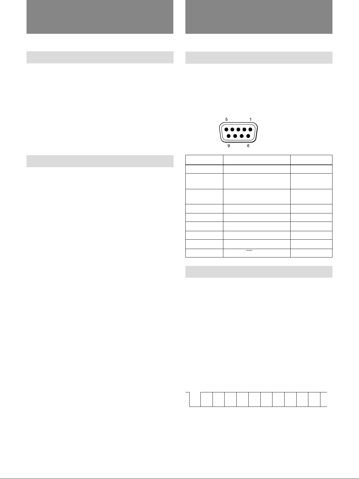
Connector Pin Assignment
The RS-232C connector is on the back of the monitor.
The signal assignment for the monitor are shown in the
table below.
Connector pin assignment
Pin number
1
2
3
4
5
6
7
8
9
Communication Parameters
Communication parameters should be set as follows.
Transmission mode : Asynchronous, bit
Data communication baud rate : 9600 bps
Parity: : Even
Stop bit length : 1
Transfer sequence : Transmission from
Signal
Unused
RX
(Monitor M Computer)
TX
(Monitor m Computer)
Unused
GND
Unused
Unused
Unused
TALLY ON/OFF
serial signal
lowest bit (LSB)
Contents
Receive Data
Transmit Data
Signal Ground
The bit composition is as follows:
1 start bit + 8 DATA bits + 1 PARITY bit + 1 STOP
bit
1
(Mark)
Start
Bit 0
bit
Bit 1 Bit 2 Bit 3 Bit 4 Bit 5 Bit 6 Bit 7
(LSB)
(MSB)
Parity
bit
Stop
bit
0
(Space)
3
Page 4

Communication via the RS-232C Interface
Command Block Format
Data is sent between the computer and the monitor in
the following format.
STX Byte
1 byte 1 byte 1 byte 1 byte n bytes 1 byte
STX
Start of text code value: 02H (the suffix “H” indicates
a hexadecimal (16) number)
Byte Count
This indicates the number of data bytes (maximum 255
bytes) which have been inserted between this byte and
the checksum byte.
Values 00H, 01H and 02H are illegal values.
Destination address
One byte address value which defines where data
composed of the above format is transmitted to. Value
02H should be specified when the command is sent
from the computer to the monitor.
count
Destination
address
Source
address
Command block
Checksum
computer, it sends back the following responses
corresponding to the commands sent from the
computer within 9 milliseconds of receiving the
commands.
• NAK (05H)
When the received command is an undefined
command or a communication error occurs.
• Specific Code + DATA
When the received command is a question requiring
a reply.
• ACK
When the received command is anything other than
the above two.
The remote control should not issue any other
commands until the response has been received from
the monitor.
The remote control should not leave a gap between
bytes to be transmitted of more than ten milliseconds.
Otherwise the monitor will treat the message as
received in error.
If the remote control unit receives a NAK from the
monitor it must wait more than ten milliseconds before
transmitting any more messages.
Source address
One byte address which defines where the data was
sent from. This defines where the response
corresponding to commands sent will be returned
from. Values from 41H to 7FH should be specified.
when the command is sent from the computer to the
monitor.
Command block
This designates a particular command.
For detailed information, see “Command Description” on
page 6.
Checksum
This value is set to make the lower eight bits of the
sum of all bytes from the Byte Count to the Checksum
inclusive zero.
Communication Protocol
The computer takes the initiative in communication
between the computer and the monitor.
When the monitor receives a command from the
4
Starting Up the Monitor
To start up the monitor, proceed as follows.
1 Connect the serial cable to the RS-232C connector
on the back of the monitor and connect the other
end to the computer.
2 Turn on the power on the monitor.
3 Turn on the power on the computer.
4 Set the serial parameters for the computer’s RS-
232C interface.
The monitor can then be controlled from the computer.
It can also be controlled from the operation panel of
the monitor. The monitor is factory-set to LOCAL
mode. In this mode, the monitor cannot be controlled
from the computer. You should set the monitor to
REMOTE (FRONT LOCK) or REMOTE & LOCAL
mode to control the monitor from the computer using
the monitor’s on-screen menu.
For detailed information on how to select REMOTE or
REMOTE & LOCAL mode, refer to the instruction manual
supplied with the monitor.
Page 5

Control Commands
Command T able
The following tables show the commands, sent from
the computer, which control the color video monitor,
and the monitor’s responses corresponding to the
commands from the computer.
Commands from the comupter
Specific
command
21
29
2A
2B
2F
40
45
4C
4D
4E
60
61
6B
6C
6D
6E
Command name
Input Config
On Switch Function
Off Switch Function
Select Display
Select RGB MODE
WHITE BALANCE DATA
NV RAM Save
Sub Control Data
Landing Data
Reset Data
Input Config Sense
White Balance Sense
Sub Control Sense
Landing Sense
Status Sense
Status Remote
Data bytes
3
1
1
1
1
*
2
*
1
3
0
1
1
0
1
0
Response from the monitor
Specific
command
04
04
04
04
04
04
04
04
04
04
70
71
7B
7C
7D
7E
05
Command name
ACK
ACK
ACK
ACK
ACK
ACK
ACK
ACK
ACK
ACK
Input Config Reply
White Balance Reply
Sub Control Reply
Landing Reply
Status Reply
Status Remote Reply
NAK Reply (error)
Data bytes
0
0
0
0
0
0
0
0
0
0
2
7
*
1
*
1
1
• Numeric values in the table are hexadecimal (16)
numbers.
• * indicates that the number of bytes varies depending
on the number of data items.
5
Page 6

Command Description
Input Config (21H)
This command controls the current video signal being
displayed on the monitor.
You can select the input connector, sync signal,
underscan mode, preset white balance and VTR
connected to RGB/COMPONENT A or B connector
using this command.
The command has two parts
• First byte: Item to be changed
• 2nd and 3rd bytes: Item settings
First byte
The first byte defines the item to be changed.
The bit assignment of the first byte is as follows.
The bit corresponding to an item to be changed is set
to 1. bits and their values are always ignored.
MSB
AFC
Underscan
Sync signal
Input connector
LSB
Preset white balance
a)
Sync signal
EXT SYNC = 0
SYNC ON G/Y = 1
Underscan mode
Normal scan = 00
Underscan = 01
Preset white balance
6500K = 00
5600K = 01
USER 1 = 10
USER 2 = 11
AFC time constant
FAST = 0
SLOW = 1
On Switch Function (29H)
This command toggles a monitor function to the on
state.
The function to be toggled on is determined by the
byte data sent after the command code 29H.
The following table shows the functions that can be
specified and what action is taken.
a) The item is effective when RGB/COMPONENT A or B is
selected.
Bits which are not specified here are undefined
2nd and 3rd bytes
The 2nd and 3rd bytes are the settings for the items
defined in the first byte.
The bit assignments of bytes 2 and 3 are as follows.
Preset white balance
AFC
Underscan mode
Sync signal
Input connector
Bits which are not specified here are undefined bits
and their values are always ignored.
The values are specified as follows.
Input connector
LINE A = 000
LINE B = 001
RGB/COMPONENT A = 010
RGB/COMPONENT B = 011
6
Function
REMOTE
DEGAUSS
a)
TALLY
POWER SAVING
(30 MIN)
a) The tally control connection on the RS-232C connector
b) To reduce the power consumption to approx. 25% 10
b)
takes precedence over this On Switch Function (29H)
command. However, the settings toggled by this
command are written to the monitor’s nonvolatile RAM.
minutes after sensing the absence of a sync signal, use
the on-screen menu function.
For details, refer to the instruction manual supplied with
the monitor.
Byte data
30H
31H
35H
37H
Action taken
REMOTE ON
DEGAUSS ON
TALLY ON
POWER SAVING
(30 MIN) ON
Page 7

Off Switch Function (2AH)
Select RGB Mode (2FH)
This commands toggles a monitor function to the off
state.
The function to be toggled off is determined by the
byte data sent after 2AH.
Function
REMOTE
a)
TALLY
POWER SAVING
(30 MIN)
a) The tally control connection on the RS-232C connector
takes precedence over this On Switch Function (29H)
command. However, the settings toggled by this
command are written to the monitor’s nonvolatile RAM.
Byte data
30H
35H
37H
Action taken
REMOTE & LOCAL
TALLY OFF
POWER SAVING (30
MIN) OFF
Select Display (2BH)
This command selects the language to display text in.
The bit assignment is as follows.
This command defines the RGB mode selection for the
monitor.
The bit assignment is as follows.
Sync signal when using the RGB/
COMPONENT A input connector
Video signal when using the RGB/
COMPONENT A input connector
Sync signal when using the RGB/COMPONENT B
input connector
Video signal when using the RGB/COMPONENT B
input connector
Bits which are not specified here are undefined bits
and their values are always ignored.
The values are specified as follows.
Video signal when using the RGB/COMPONENT B
input connector
RGB = 01
COMPONENT = 10
Selected language
The bits values for each language are as follows.
ENGLISH = 001
GERMAN = 010
FRENCH = 011
ITALIAN = 100
SPANISH = 101
Sync signal when using the RGB/COMPONENT B
input connector
SYNC ON G/Y = 01
EXT SYNC = 10
Video signal when using the RGB/COMPONENT
A input connector
RGB = 01
COMPONENT = 10
Sync signal when using the RGB/COMPONENT A
input connector
SYNC ON G/Y = 01
EXT SYNC = 10
7
Page 8

Command Description
White Balance Data (40H)
This command adjusts the white balance in the
monitor’s volatile RAM.
To save data, see the next “NV RAM Save (45H)”
command.
The command has multiple parts.
First byte: User setting
2nd byte: White balance items to be modified
3rd and subsequent bytes: White balance value for the
item specified in the 2nd byte
The number of bytes in this command is determined by
the number of white balance adjustments to be made.
First byte
User area
Sets 1 in the user area bit in the first byte of data in the
message command block.
2nd byte
The 2nd byte specifies the white balance items to be
adjusted.
Multiple white balance items can be specified.
The values of data to be adjusted are indicated by a 1
being set in the appropriate bit position. Otherwise a 0
in the bit position indicates no data to be changed.
Bits which are not specified here are undefined b its
and their values are always ignored.
NV RAM Save (45H)
This command stores data to non-volatile RAM.
The command has two portions.
First byte: Informs the monitor that data in the user
area will be modified.
2nd byte: Items to be saved
First byte
User area
Set 1 to the user area bit of the first byte of the data
within the command block of the message.
2nd byte
The 2nd byte specifies the items to be saved to NV
RAM.
The bit assignment is as follows.
Sub control data
White balance data (RAM data m USER 1)
White balance data (RAM data m USER 1)
Landing data
R GAIN
G GAIN
B GAIN
R BIAS
G BIAS
B BIAS
Bits which are not specified here are undefined bits
and their values are always ignored.
3rd and subsequent bytes
White balance value
The data bytes starts at the Least Significant Bit end of
the item being sent. I.e., if the data to be adusted is R
GAIN, the first byte of white balance data is R GAIN.
8
Set 1 in the bits corresponding to the items to be saved
to NV RAM.
Bits which are not specified here are undefined bits
and their values are always ignored.
Page 9

Sub Control Data (4CH)
Landing Data (4DH)
This command adjusts the monitor sub control data. To
save adjusted data, see the command “NV RAM Save
(45H)”.
The command has two parts.
First byte: Items to be adjusted
2nd and subsequent bytes: Data values to be set
First byte
This byte specifies items to be adjusted. A 1 in the
appropriate bit position indicates that data for that item
is to be changed. A 0 in the bit position indicates no
data to be changed.
The bit assignment is as follows.
CHROMA
BRIGHTNESS
APERTURE
CONTRAST
VOLUME
Bits which are not specified here are undefined bits
and their values are always ignored.
2nd and subsequent bytes
One byte of data can be specified for each item
specified in the first byte, up to a maximum value of
100 (7 bit data, MSB always 0).
The data bytes start at the Least Significant Bit end of
the item being sent. I.e. if the data to be adjusted is
APERTURE and CONTRAST, then the first byte of
data is APERTURE and the last byte is CONTRAST.
The factory-set value of each item is as follows:
VOLUME and APERTURE: 0 (STD)
CONTRAST, BRIGHTNESS and CHROMA: 50
(STD)
If the number of bytes of data does not match the
number of items specified in the first byte, no values
are changed and the command is ignored.
This command adjusts landing data .
Data is specified in one byte, up to a maximum value
of 100.
The factory-set value is 50 (STD).
To save the adjusted data, see the “NV RAM Save
(45H)” command.
Reset Data (4EH)
This command resets data in the monitor to the factory
set values.
The command has three parts.
• First byte: Data to be reset
• 2nd byte: White balance data items specified in the
first byte which are to be reset.
• 3rd byte: Sub control data items specified in the first
byte which are to be reset.
First byte
Data to be reset to the factory-set value are specified in
this byte.
The data to be reset is indicated by 1 being set in the
appropriate bit position. Otherwise 0 in the bit position
indicates no data to be reset.
The bit assignment is as follows.
USER 2 white balance data
USER 1 white balance data
SUB CONTROL data
LANDING data
2nd byte
This byte specifies which white balance data items,
specified in the first byte, are to be reset.
R GAIN
G GAIN
B GAIN
R BIAS
G BIAS
B BIAS
Set 1 in the bit for the item to be reset.
9
Page 10

Command Description
3rd byte
This byte specifies which sub control data items,
specified in the first byte, are to be reset.
CHROMA
BRIGHTNESS
APERTURE
CONTRAST
VOLUME
Set 1 in the bit for the item to be reset.
Input Config Sense (60H)
This command requests the current status of the input
signals of the monitor.
The monitor returns the Input Config Replay (70H) to
the computer.
White Balance Sense (61H)
Sub Control Sense (6BH)
This command requests sub control data from the
monitor.
The bit assignment is as follows.
CHROMA
BRIGHTNESS
APERTURE
CONTRAST
VOLUME
Set 1 in the bit for the item requested.
Landing Sense (6CH)
This monitor requests the landing data.
The monitor returns the landing data response with the
Landing Replay (7CH) command.
This command requests the white balance data stored
in RAM in the monitor.
Set 1 in the white balance data request bit. Bits other
than that are undefined bits and their values are always
ignored.
White balance data request
The monitor returns the response with the White
Balance Replay (71H) command.
Status Sense (6DH)
This command requests the status of the monitor’s
current operation.
The bit assignment is as follows.
DISPLAY
RGB MODE
Set 1 in the item which should be in the response.
The monitor returns the response with the Status
Replay (7DH) command.
Status Remote (6EH)
This command requests the current status of the
monitor’s remote control function.
The monitor returns the response with the Status
Remote Reply (7EH) command.
10
Page 11

Input Config Reply (70H)
The monitor returns the current status of the currently
selected input signal using two bytes with the same bit
assignment as the Input Config (21H) command.
White Balance Reply (71H)
The monitor returns the response for the current status
of the white balance data.
This replay command has two parts
First byte: Specification of white balance data
2nd and subsequent bytes: Response data
First byte
The bit assignment is as follows.
First byte
1 is set in the item to be responded in the first byte.
The bit assignment is as follows.
CHROMA
BRIGHTNESS
APERTURE
CONTRAST
VOLUME
2nd and subsequent bytes
Each response is one-byte data.
The response data bytes start at the Least Significant
Bit end of the item to be specified in the first byte.
I.e., if the data requested is CHROMA, the first data
value byte is CHROMA.
For details, see “Sub Control Data” command on page 9.
White balance data reply
Set 1 to the white balance response bit.
2nd and subsequent bytes
Each item of white balance data is returned in one byte
in the following order.
R GAIN
G GAIN
B GAIN
R BIAS
G BIAS
B BIAS
Sub Control Reply (7BH)
The monitor returns the response with the Sub Control
Reply (7BH) command.
The command has two parts:
First byte: Items for which the current status is
reported.
2nd and subsequent bytes: Current status data for the
requested item.
Landing Reply (7CH)
The monitor returns the landing data response with this
command.
For details of the response value, see the “Landing Data
(4DH)” command on page 9.
Status Reply (7DH)
The monitor returns the response of the item requested
with the Status Sense command with this command.
1 is set to the items to be responded in the first byte.
DISPLAY
RGB MODE
Each response data is one-byte data.
The response data bytes start at the Least Significant
Bit end of the item to be specified in the first byte. I.e.,
if the data to be responded is DISPLAY, the first data
value byte is DISPLAY.
For the bit assignment of RGB MODE, see “Select RGB
Mode (2FH)” command on page 7.
For the bit assignment of DISPLAY, see “Select Display
(2BH)” command on page 7.
11
Page 12

Command Description
Status Remote Reply (7EH)
The monitor returns the current remote status of the
monitor. The monitor always replies to the Status
Remote (6EH) command regardless of the actual
remote state.
The bit assignment is as follows.
Type of remote control
Control mode applied
Control mode applied
Remote mode = 01
Local mode = 10
Remote & Local mode = 11
Type of remote control
This value should always be 10 (serial).
ACK Reply (04H)
The bit assignment is as follows.
Undefined message
Checksum error in received message
Parity error in received message
Overrun error in received message
Framing error in received message
Timeout error
Timeout error
When the time between bytes is less than 10ms, the
byte value is 0.
When the time between bytes exceeds 10ms, an error
occurs and the byte value is 1.
Framing error in received message
No error = 0
When the received message has a framing error =1
Overrun error in received message
No error = 0
When the received message has an overrun error = 1
The monitor returns this command when the monitor
receives a command.
NAK Reply (05H)
The monitor retruns this command when an error
occurs in the serial communications.
When the monitor is in LOCAL mode, the monitor
returns the response to the Status Remote (6EH)
command. When the monitor receives a command
other than the Status Remote (6EH) command in
LOCAL mode, the monitor returns 0 corresponding to
the bit of undefined message of the NAK Replay
(05H).
Parity error in received message
No error = 0
When the received message has a parity error = 1
Checksum error in received message
No error = 0
When the received message has a checksum error = 1
Undefined message
When the monitor understands the received message =
0
When the monitor is in LOCAL mode and receives
this command, the monitor returns 0 for this item.
When the monitor does not understand the received
message = 1
Sony Corporation Printed in Japan
 Loading...