

Sony TRINITRON PVM-14M2U, HR TRINITRON PVM-14M4U, TRINITRON PVM-14M2A, TRINITRON PVM-14M2E, HR TRINITRON PVM-14M4E Service Manual
...
llllillll~lllll~IIIIIIIIIIIIIIIIIIIIIIIIIIIIIIIHll~IIIIIIIIII
SERVICE MANUAL
SONY - SP0401
MODEL
...............
PVM-14M2U
PVM-14M4U
PVM-14M2E
OEST. CHASSIS Na MODEL
us
Canadian SCC-G61J-A PVM-14M4E
us
Canadian SCC-G61G·A PVM-14M2A
AEP SCC-G62HA PVM-14M4A
CJ
OEST. CHASSIS.Na
AEP SCC-G62F-A
Australian SCC-N17 A-A
Australian SCC-N17B-A
111
11
11111,::11: Trinitron Trinitron
PVM-14M4U/14M4E PVM-14M2U/14M2E
TRINITRON® COLOR VIDEO MONITOR
SONY.
SPECIFICATIONS
Video signal
For PVM-14M4U/14M4E/20M4U/20M4E:
Color system
Resolution
Aperture correction
Frequency response
LINE
RGB
NTSC, PAL, SECAM, NTSC4.43
800 TV lines
0dB to+6dB
10 MHz± 3 dB (Y signal)
lOMHz± 3 dB
Synchronization AFC time constant 1.0 msec.
For PVM-14M2U/14M2E/20M2U/20M2E:
Color system
Resolution
Aperture correction
Frequency response
LINE
RGB
Synchronization
NTSC, PAL, SECAM, NTSC4.43
600 TV lines
0dB to +6 dB
10 MHz± 3 dB (Y signal)
lOMHz± 3 dB
AFC time constant 1.0 msec.
Picture performance
For PVM-14M4U/14M4E/14M2U/14M2E:
Normal scan
Under scan
H. linearity
V. linearity
Convergence
7 % over scan of CRT effective screen
area
5 % underscan of CRT effective screen
area
Less than 4.0 % (typical)
Less than 4.0 % (typical)
Central area: 0.4 mm (typical)
Peripheral area: 0.5 mm (typical)
Raster size stability H: 1.0%, V: 1.5%
High voltage regulation
3.5 %
Color temperature D65/093, selectable
USER (3,200K-10,000K, factory
setting is D65)
For PVM-20M4U/20M4E:
Normal scan
Under scan
H. linearity
V. linearity
Convergence
7 % over scan of CRT effective screen
area
5 % underscan of CRT effective screen
area
Less than 5.0 % (typical)
Less than 5.0 % (typical)
Central area: 0.5 mm (typical)
Peripheral area: 0.7 mm (typical)
Raster size stability H: 1.0%, V: 1.5%
High voltage regulation
4.0%
Color temperature D65/093, selectable
USER (3,200K-10,000K, factory
setting is D65)
For PVM-20M2U/20M2E
Normal scan
Under scan
H. linearity
V. linearity
Convergence
7 % over scan of CRT effective screen
area
5 % underscan of CRT effective screen
area
Less than 5.0 % (typical)
Less than 5.0 % (typical)
Central area: 0.6 mm (typical)
Peripheral area: 1.0 mm (typical)
Raster size stability H: 1.0%, V: 1.5%
High voltage regulation
4.0%
Color temperature D65/093, selectable
Inputs
USER (3,200K-10,000K, factory
setting is D65)
For PVM-14M4U/14M4E/20M4U/20M4E:
LINEA/B
VIDEO IN
AUDIO IN
LINEC
BNC connector (x2), lVp-p ±6 dB,
sync negative
Automatic 75 ohms termination
Phono jack (x2), -5 dBual, more than
47 kilo-ohms
Y/C IN 4-pin mini-DIN (xl)
See the pin assignment on page 19.
AUDIO IN Phono jack (xi), -5 dBual, more than
47 kilo-ohms
RGB/COMPONENT
R/R-Y,G/Y,B/B-Y IN: BNC connector (x3)
R, G, B channels: 0.7 Vp-p, ±6 dB
Sync on green: 0.3 Vp-p, negative
R-Y, B-Y channels: 0.7 Vp-p, ±6 dB
Y channel: 0.7 Vp-p, ±6 dB
(Standard color bar signal of 75%
chrominance)
Automatic 75 ohms termination
AUDIO IN Phono jack (xi), -5 dBu8l, more than
47 kilo-ohms
EXT SYNC IN
REMOTE
BNC connector (xl)
4 Vp-p, ±6 dB, sync negative
20-pin connector (xl)
See the pin assignment on page 19.
a) 0 dBu = 0.775 Vr.m.s.
-2-
For PVM-14M2U/14M2E/20M2U/20M2E:
LINEA/B
VIDEO IN
AUDIO IN
LINEC
Y/CIN
AUDIO IN
BNC connector (x2), 1 Vp-p
± 6dB, sync negative
Automatic 75 ohms termination
Phono jack (x2), -5 dBua), more than
47 kilo-ohms
4-pin mini-DIN (xl)
See the pin assignment on page 19.
Phono jack (xl), -5 dBu
8
), more than
47 kilo-ohms
ROB/COMPONENT
R/R-Y,G/Y,B/B-Y IN: BNC connector (x3)
R, G, B channels: 0.7 Vp-p ± 6dB
Sync on green: 0.3 Vp-p negative
R-Y, B-Y channel: 0.7 Vp-p ± 6dB
Y channel: 0.7 Vp-p ± 6dB
(Standard color bar signal of 75%
chrominance)
Automatic 75 ohms termination
AUDIO IN Phono jack (xl), -5 dBua), more than
47 kilo-ohms
EXT SYNC IN
REMOTE
BNC connector (xl)
4 Vp-p, ±6 dB, sync negative
20-pin connector (xl)
See the pin assignment on page 19.
a) OdBu == 0.775 Vr.m.s.
Outputs (common to all models)
LINEA/B
VIDEO OUT
AUDIO OUT
LINEC
Y/COUT
BNC connector (x2) loop-through,
Automatic 75 ohms termination
Phono jack (x2) loop-through
4-pin mini-DIN (xl) loop-through,
Automatic 75 ohms termination
AUDIO OUT Phono jack (xl) loop-through
ROB/COMPONENT
R/R-Y,G/Y,B/B-Y OUT: BNC connector (x3)
loop-through
Automatic 75 ohms termination
AUDIO OUT Phonojack (xl) loop-through
EXT SYNC OUT BNC connector (xl)
Automatic 75 ohms termination
Speaker output Output level: 0.8 W
General
For PVM-14M4U:
CRT SMPTE-C phosphor
Power consumption 90 Wh (with SDI: 99 Wh)
Power requirements 120 V AC, 50/60Hz
Operating temperature
0 to +35°C (32 to 95°F)
Storage temperature -10 to +40°C (14 to104°P)
Operating humidity 35 to 85% (no condensation)
Storage humidity O to 90%
Dimensions (w/h/d) Approx. 346 x 340 x 431 mm
(135hx 13½ x 17 inches)
not incl. projecting parts and controls
Mass Approx. 16.7kg (36 lb 13 oz)
Accessory supplied AC power cord (1)
AC plug holder (1)
Tally label (1)
Cable with a 20-pin connector (1)
For PVM-14M4E:
CRT EBU phosphor
Power consumption 90 Wh (with SDI: 99 Wh)
Power requirements 100 to 240 V AC, 50/60Hz
Operating temperature
0 to +35°C (32 to 95°P)
Storage temperature -10 to +40°C (14 to 104 °P)
Operating humidity 35 to 85% (no condensation)
Storage humidity 0 to 90%
Dimensions (w/h/d) Approx. 346 x 340 x 431 mm
(135hx 13½ x 17 inches)
not incl. projecting parts and controls
Mass Approx. 16.7kg (36 lb 13 oz)
Accessory supplied AC power cord (1)
AC plug holder (1)
Tally label (1)
Cable with a 20-pin connector (1)
For PVM-14M2U:
CRT P-22 phosphor
Power consumption 90 Wh (with SDI: 99 Wh)
Power requirements 120 V AC, 50/60Hz
Operating temperature
0 to +35°C (32 to 95°P)
Storage temperature -10 to +40°C (14 to 104 °P)
Operating humidity 35 to 85% (no condensation)
Storage humidity 0 to 90%
Dimensions ( w/h/d) Approx. 346 x 340 x 431 mm
(135hx 13
1
/2 x 17 inches)
not incl. projecting parts and controls
Mass Approx. 16.7kg (36 lb 13 oz)
Accessory supplied AC power cord (1)
AC plug holder (1)
Tally label (1)
Cable with a 20-pin connector (1)
-3-
For PVM-14M2E:
CRT P-22 phosphor
Power consumption 90 Wh (with SDI: 99 Wh)
Power requirements 100 to 240 V AC, 50/60Hz
Operating temperature
0 to +35°C (32 to 95°F)
Storage temperature -10 to +40°C (14 tol04°F)
Operating humidity 35 to 85% (no condensation)
Storage humidity O to 90%
Dimensions (w/h/d) Approx. 346 x 340 x 431 mm
(13% x 13½ x 17 inches)
not incl. projecting parts and controls
Mass Approx. 16.7kg (36 lb 13 oz)
Accessory supplied AC power cord ( 1)
AC plug holder (1)
Tally label (1)
Cable with a 20-pin connector (1)
For PVM-20M4U:
CRT SMPTE-C phosphor
Power consumption 125 Wh (with SDI: 135 Wh)
Power requirements 120 V AC, 50/60Hz
Operating temperature
0 to +35°C (32 to 95°F)
Storage temperature - 10 to +40°C (14 to 104 °F)
Operating humidity 35 to 85% (no condensation)
Storage humidity O to 90%
Dimensions (w/h/d) Approx. 450 x 458 x 503 mm
(17% x 18
1
/2! x 19
7
/s inches)
not incl. projecting parts and controls
Mass Approx. 30.0 kg (66 lb 2 oz)
Accessory supplied AC power cord (1)
AC plug holder (1)
Tally label (1)
Cable with a 20-pin connector (1)
For PVM-20M4E:
CRT EBU phosphor
Power consumption 130 Wh (with SDI: 140 Wh)
Power requirements 100 to 240 V AC, 50/60Hz
Operating temperature
0 to +35°C (32 to 95°F)
Storage temperature -10 to +40°C (14 tol04°F)
Operating humidity 35 to 85% (no condensation)
Storage humidity O to 90%
Dimensions (w/h/d) Approx. 450 x 458 x 503 mm
(17% x 181/s x 19
7
/2! inches)
not incl. projecting parts and controls
Mass Approx. 30.0 kg (66 lb 2 oz)
Accessory supplied AC power cord ( 1)
AC plug holder (1)
Tally label (I)
Cable with a 20-pin connector (1)
For PVM-20M2U:
CRT P-22 phosphor
Power consumption 115 Wh (with SDI: 125 Wh)
Power requirements 120 V AC, 50/60Hz
Operating temperature
0 to +35°C (32 to 95°F)
Storage temperature -10 to +40°C (14 tol04°F)
Operating humidity 35 to 85% (no condensation)
Storage humidity O to 90%
Dimensions (w/h/d) Approx. 450 x 458 x 503 mm
(17% x18¼ x 19
7
/2! inches)
not incl. projecting parts and controls
Mass Approx. 30.0 kg (66 lb 2 oz)
Accessory supplied AC power cord (1)
AC plug holder (1)
Tally label (1)
Cable with a 20-pin connector (1)
For PVM-20M2E:
CRT P-22 phosphor
Power consumption 120 Wh (with SDI: 130 Wh)
Power requirements 100 to 240 V AC, 50/60Hz
Operating temperature
0 to +35°C (32 to 95°F)
Storage temperature -10 to +40°C (14 tol04°F)
Operating humidity 35 to 85% (no condensation)
Storage humidity O to 90%
Dimensions (w/h/d) Approx. 450 x 458 x 503 mm
(17% xl8
1
Ai x 19
7
/2! inches)
not incl. projecting parts and controls
Mass Approx. 30.0 kg (66 lb 2 oz)
Accessory supplied AC power cord (I)
AC plug holder (1)
Tally label (1)
Cable with a 20-pin connector (1)
Design and specifications are subject to change
without notice.
-4-
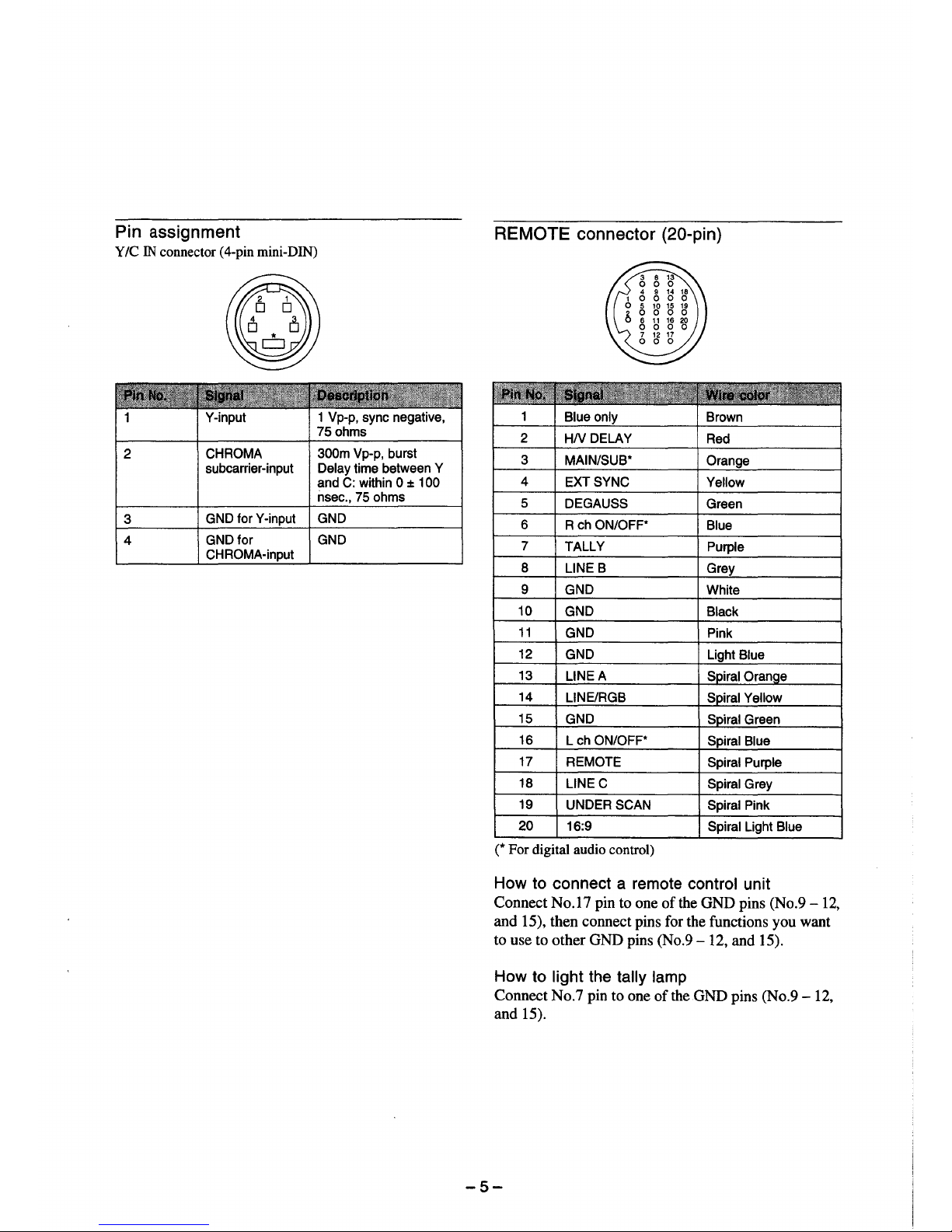
Pin assignment
Y/C IN connector (4-pin mini-DIN)
Y-input 1 Vp-p, sync negative,
75 ohms
2
CHROMA 300m Vp-p, burst
subcarrier-input Delay time between Y
and C: within O ± 100
nsec., 75 ohms
3
GND for Y-input GND
4
GND for GND
CHROMA-input
REMOTE connector (20-pin)
1
Blue only Brown
2
HNDELAY
Red
3 MAIN/SUB*
Orange
4
EXT SYNC
Yellow
5
DEGAUSS
Green
6 R ch ON/OFF*
Blue
7
TALLY
Purple
8 LINE B
Grey
9 GND
White
10
GND
Black
11
GND Pink
12
GND
13
LINEA
14
LINE/RGB
15
GND
16
L ch ON/OFF*
Spiral Blue
17
REMOTE
Spiral Purple
18
LINE C
Spiral Grey
19
UNDER SCAN
Spiral Pink
20
16:9
Spiral Light Blue
(* For digital audio control)
How to connect a remote control unit
Connect No.17 pin to one of the GND pins (No.9 - 12,
and 15), then connect pins for the functions you want
to use to other GND pins (No.9- 12, and 15).
How to light the tally lamp
Connect No.7 pin to one of the GND pins (No.9 - 12,
and 15).
-5-
SAFETY CHECK-OUT
(US Model only)
After correcting the original service problem,
perform the following safety checks before releasing
the set to the customer:
1. Check the area of your repair for unsoldered or
poorly-soldered connections. Check the entire
board surface for solder splashes and bridges.
2. Check the interboard wiring to ensure that no
wires are "pinched" or contact high-wattage
resistors.
3. Check that all control knobs, shields, covers,
ground straps, and mounting hardware have
been replaced. Be absolutely certain that you
have replaced all the insulators.
4. Look for unauthorized replacement parts, particularly transistors. that were installed during
a previous repair. Point them out to the customer and recommend their replacement.
5. Look for parts which, though functioning, show
obvious signs of deterioration. Point them out
to the customer and recommend their replacement.
6. Check the line cords for cracks and abrasion.
Recommend the replacement of any such line
cord to the customer.
7. Check the B+ and HV to see if they are at the
values specified. Make sure your instruments
are accurate; be suspicious of your HV meter if
sets always have low HV.
8. Check the metal trim, metallized knobs,
screws, and all other exposed metal parts
for AC leakage.
Check leakage as described below.
To Exposed Metal
Parts on Set
0.15µF 1.Skil
AC
voltmeter
(0.75V)
-= Earth Ground
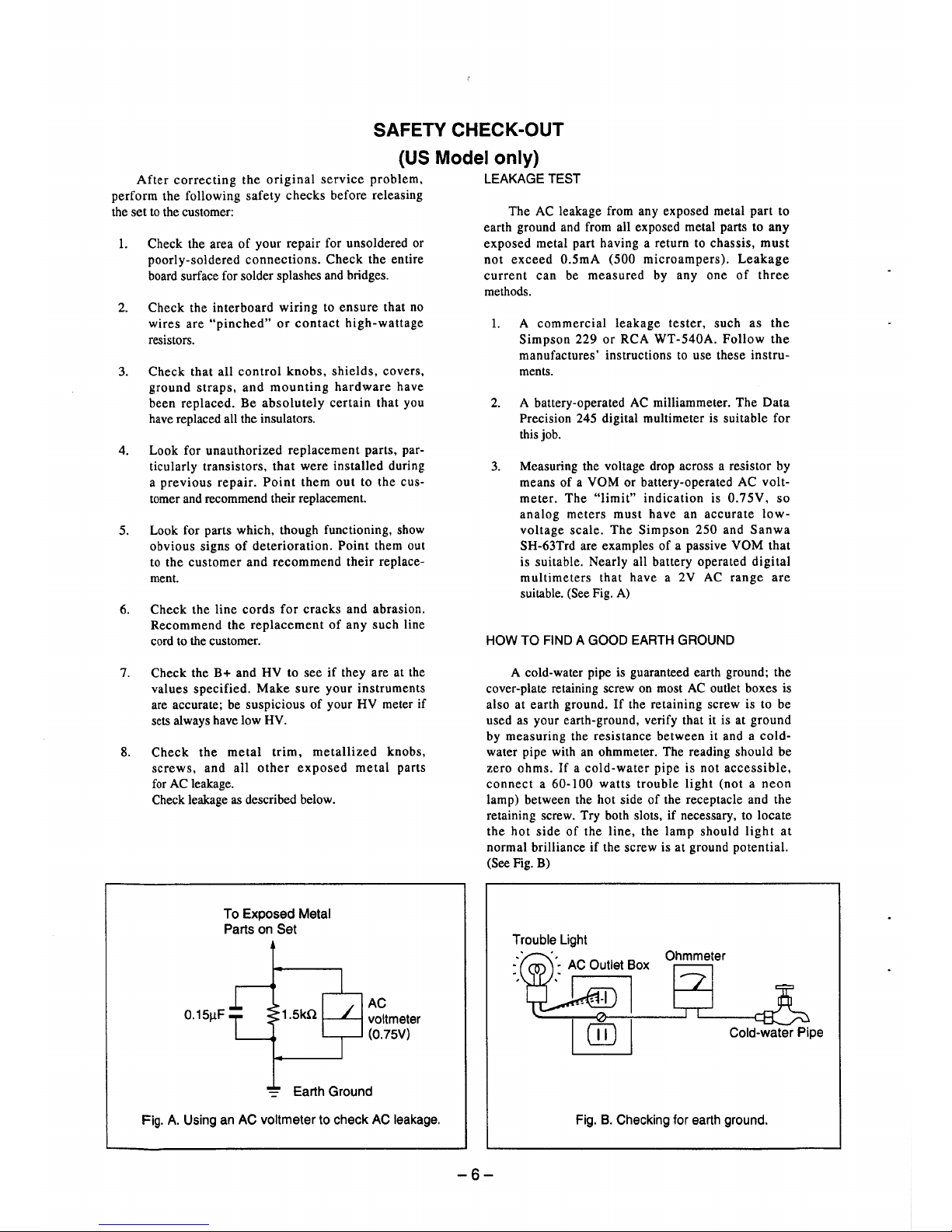
Fig. A. Using an AC voltmeter to check AC leakage.
LEAKAGE TEST
The AC leakage from any exposed metal part to
earth ground and from all exposed metal parts to any
exposed metal part having a return to chassis, must
not exceed 0.SmA (500 microampers). Leakage
current can be measured by any one of three
methods.
1. A commercial leakage tester, such as the
Simpson 229 or RCA WT-540A. Follow the
manufactures' instructions to use these instruments.
2. A battery-operated AC milliammeter. The Data
Precision 245 digital multimeter is suitable for
this job.
3. Measuring the voltage drop across a resistor by
means of a VOM or battery-operated AC voltmeter. The "limit" indication is 0. 7 5V. so
analog meters must have an accurate lowvoltage scale. The Simpson 250 and Sanwa
SH-63Trd are examples of a passive VOM that
is suitable. Nearly all battery operated digital
multimeters that have a 2V AC range are
suitable. (See Fig. A)
HOW TO FIND A GOOD EARTH GROUND
A cold-water pipe is guaranteed earth ground; the
cover-plate retaining screw on most AC outlet boxes is
also at earth ground. If the retaining screw is to be
used as your earth-ground, verify that it is at ground
by measuring the resistance between it and a coldwater pipe with an ohmmeter. The reading should be
zero ohms. If a cold-water pipe is not accessible,
connect a 60-100 watts trouble light (not a neon
lamp) between the hot side of the receptacle and the
retaining screw. Try both slots, if necessary. to locate
the hot side of the line, the lamp should light at
normal brilliance if the screw is at ground potential.
(See Fig. B)
Trouble Light
Ohmmeter
Cold-water Pipe
Fig. B. Checking for earth ground.
-6-
TABLE OF CONTENTS
Section
Title
1. GENERAL
Features............................................................................... 8
Location and Function of Pans and Controls .. .................. .. 9
Using On-screen Menus...................................................... 11
Connections......................................................................... 13
2. DISASSEMBLY
2-1. Top Cover and Rear Cover Removal...................... 14
2-2. Terminal Board Removal........................................ 14
2-3. J and H Boards Removal......................................... 14
2-4. Picture Tube Removal............................................. 14
2-5. Service Position....................................................... 15
3. SET-UP ADJUSTMENTS
3-1. Preparations (1) .................... .............. ...... ...... .. .... ... 16
3-2. Preparations (2) Initialization.................................. 19
3-3. Writing Model Data ................................................ 19
3-4. Picture Output ...... .......... ........ ............ ........ .... .. .... .. . 20
3-5. Landing Adjustment................................................ 20
3-6. Convergence Adjustment (1) .................................. 21
3-7. Deflection Yoke Neck Rotation Adjustment.......... 22
3-8. Convergence Adjustment (2) .................................. 22
3-9. G2 Adjustment ........................................................ 23
3-10. White Balance Adjustment ..................................... 23
3-11. Blue-Only White Balance Adjustment.................... 24
3-12. Sub Bn Adjustment................................................. 24
3-13. Focus Adjustment .................................................... 24
4. SAFETY RELATED ADJUSTMENT ................. 25
(CAUTION)
SHORT CIRCUIT THE ANODE OF THE PICTURE TUBE AND THE
ANODE CAP TO THE METAL CHASSIS, CRTSHIELD, OR CARBON
PAINTED ON THE CRT, AFTER REMOVING THE ANODE.
WARNING!!
AN ISOLATION TRANSFORMER SHOULD BE USED DURING ANY
SERVICE TO AVOID POSSIBLE SHOCK HAZARD, BECAUSE OF
LIVE CHASSIS.
THE CHASSIS OF THIS RECEIVER IS DIRECTLY CONNECTED TO
THE AC POWER LINE.
SAFETY-RELATED COMPONENT WARNING!!
COMPONENTS IDENTIFIED BY SHADING AND MARK & ON THE
SCHEMATIC DIAGRAMS, EXPLODED VIEWS AND IN THE PARTS
LIST ARE CRITICAL FOR SAFE OPERATION. REPLACE THESE
COMPONENTS WITH SONY PARTS WHOSE PART NUMBERS
APPEAR AS SHOWN IN THIS MANUAL OR IN SUPPLEMENTS
PUBLISHED BY SONY. CIRCUIT ADJUSTMENTS THAT ARE
CRITICAL FOR SAFE OPERATION ARE IDENTIFIED IN THIS
MANUAL. FOLLOW THESE PROCEDURES WHENEVER CRITICAL
COMPONENTS ARE REPLACED OR IMPROPER OPERATION IS
SUSPECTED.
Section
5. CIRCUIT ADJUSTMENTS
5-1. A Board Adjustments .............................................. 27
6. DIAGRAMS
6-1. Block Diagrams (1) ................................................. 39
Block Diagrams (2) ................................................. 44
6-2. Frame Schematic Diagram ...................................... 49
6-3. Circuit Boards Location .......................................... 52
6-4. Printed Wiring Boards and Schematic Diagrams.... 52
• A Board (1/3) ........................................................ 59
• A Board (2/3) ........................................................ 66
• A Board (3/3) ........................................................ 69
•QBoard ................................................................. 74
• G Board ................................................................. 76
• J Board .................................................................. 76
•X Board ................................................................. 76
• H Board ................................................................. 78
• S Board ................................................................. 78
• C Board ................................................................. 83
6-5. Semiconductors ....................................................... 87
7. EXPLODED VIEWS
7-1. Chassis ..................................................................... 89
7-2. Picture Tube ............................................................ 90
8. ELECTRICAL PARTS LIST.............................. 91
-7-
(ATTENTION)
APRES AVOIR DECONNECTE LE CAP DE L'ANODE, COURTCIRCUITER L'ANODE DU TUBE CATHODIQUE ET CELUI DE
L'ANODE DU CAP AU CHASSIS METALLIQUE DE L'APPAREIL, OU
AU COUCHE DE CARBONE PEINTE SUR LE TUBE CATHODIQUE
OU AU BUNDAGE DU TUBE CATHODIQUE.
ATTENTION!!
AFIN D'EVITER TOUT RESQUE D'ELECTROCUTION PROVENANT
D'UN CHASSIS SOUS TENSION, UN TRANSFORMATEUR
D'ISOLEMENT DOIT ETRE UTILIS~ LORS DE TOUT DEPANNAGE.
LE CHASSIS DE CE RECEPTEUR EST DIRECTEMENT RACCORDE
A L'ALIMENTATION SECTEUR.
ATTENTION AUX COMPOSANTS RELATIFS A LA
S~CURITE!!
LES COMPOSANTS IDENTIFl~S PAR UNE TRAME ET PAR UNE
MARQUE & SUR LES SCHEMAS DE PRINCIPE, LES VUES
EXPLOSEES ET LES USTES DE PIECES SONT D'UNE IMPORTANCE
CRITIQUE POUR LA S~CURIT~ DU FONCTIONNEMENT. NE LES
REMPLACER QUE PAR DES COMPOSANTS SONY DONT LE
NUMERO DE Pl~CE EST INDIQU~ DANS LE PR~SENT MANUEL OU
DANS DES SUPPLEMENTS PUBLl~S PAR SONY. LES R~GLAQES
DE CIRCUIT DONT L'IMPORTANCE EST CRITIQUE POUR LA
SECURITE DU FONCTIONNEMENT SONT IDENTIFIES DANS LE
PR~SENT MANUEL SUIVRE CES PROC~DURES LORS DE CHAQUE
REMPLACEMENT DE COMPOSANTS CRITIQUES, OU LORSQU'UN
MAUVAIS FONCTIONNEMENT EST SUSPECTE.
I
CX)
I
SECTION 1
GENERAL
The operating instructions mentioned here are partial abstracts from
the Operating Instruction Manual. The page numbers of the
Operating Instruction Manual remain as in the manual.
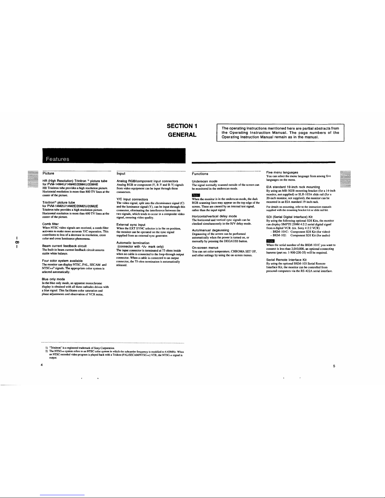
Features
Picture
HR (High Resolution) Trinitron
11
picture tube
for PVM-14M4U/14M4E/20M4U/20M4E
HR Trinitron tube provides a high resolution picture.
Horizontal resolution is more than 800 TV lines at the
center of the picture.
Trinitron'' picture tube
for PVM-14M2U/14M2E/20M2U/20M2E
Trinitron tube provides a high resolution picture.
Horizontal resolution is more than 600 TV lines at the
center of the picture.
Comb filter
When NTSC video signals are received, a comb filter
activates to make more accurate Y/C separation. This
contributes to less of a decrease in resolution, cross
color and cross luminance phenomena.
Beam current feedback circuit
The built-in beam current feedback circuit assures
stable white balan~e.
Four color system available
The monitor can display NTSC, PAL, SECAM and
NTSCw
21
signals. The appropriate color system is
selected automatically.
Blue only mode
In the blue only mode, an apparent monochrome
display is obtained with all three cathodes driven with
a blue signal. This facilitates color saturation and
phase adjustments and observation of VCR noise.
1) 'Trinilron" is a registered trademark of Sony Corporation.
Input
Analog RGB/component input connectors
Analog RGB or component (Y, R-Y and B-Y) signals
from video equipment can be input through these
connectors.
Y/C input connectors
The video signal, split into the chrominance signal (C)
and the luminance signal (Y), can be input through this
connector, eliminating the interference between the
two signals, which tends to occur in a composite video
signal, ensuring video quality.
External sync input
When the EXT SYNC selector is in the on position,
the monitor can be operated on the sync signal
supplied from an external sync generator.
Automatic termination
(connector with J\/1,- mark only)
The input connector is terminated al 75 ohms inside
when no cable is connected to the loop-through output
connector. When a cable is connected to an output
connector, the 75-ohm termination is automatically
released.
2) The NTSCu, system refers to an NTSC color system in which the subcarrier frequency is modified to 4.43MHz. When
an NTSC recorded video program is played back with a Trident (PAUSECAMJNTSC. o) VTR, the NTSC..o signal is
oulput.
4
Functions
Underscan mode
The signal normally scanned outside of the screen can
be monitored in the underscan mode.
11111111
When the monitor is in the underscan mode, the dark
RGB scanning lines may appear on the top edge of the
screen. These are caused by an internal test signal,
rather than the input signal.
Horizontal/vertical delay mode
The horizontal and vertical sync signals can be
checked simultaneously in the HIV delay mode.
Auto/manual degaussing
Degaussing of the screen can be performed
automatically when the power is turned on, or
manually by pressing the DEGAUSS bulton.
On-screen menus
You can set color temperature, CHROMA SET UP,
and other settings by using the on-screen menus.
Five menu languages
You can select the menu language from among five
languages on the menu.
EIA standard 19-inch rack mounting
By using an MB-502B mounting bracket (for a 14-inch
monitor, not supplied) or SLR-I 03A slide rail (for a
20-inch monitor, not supplied), the monitor can be
mounted in an EIA standard 19-inch rack.
For details on mounting, refer to the instruction manuals
supplied with the mounting bracket kit or slide rail kit.
SDI (Serial Digital Interface) Kit
By using the following optional SDI Kits, the monitor
can display SMPTE 259M 4:2:2 serial digital signal
from a digital VCR. (ex. Sony 4:2:2 VCR)
-BKM-IOIC: Component SDI Kit (for video)
- BKM-102: Component SDI Kit (for audio)
IE!I
When the serial number of the BKM-IOIC you want to
connect is less than 2,010,000, an optional connecting
harness (part no. 1-900-230-35) will be required.
Serial Remote Interface Kit
By using the optional BKM-103 Serial Remote
Interface Kit, the monitor can be controlled from
personal computers via the RS-422A serial interface.
5
(0
I
Location and Function of Parts and Controls
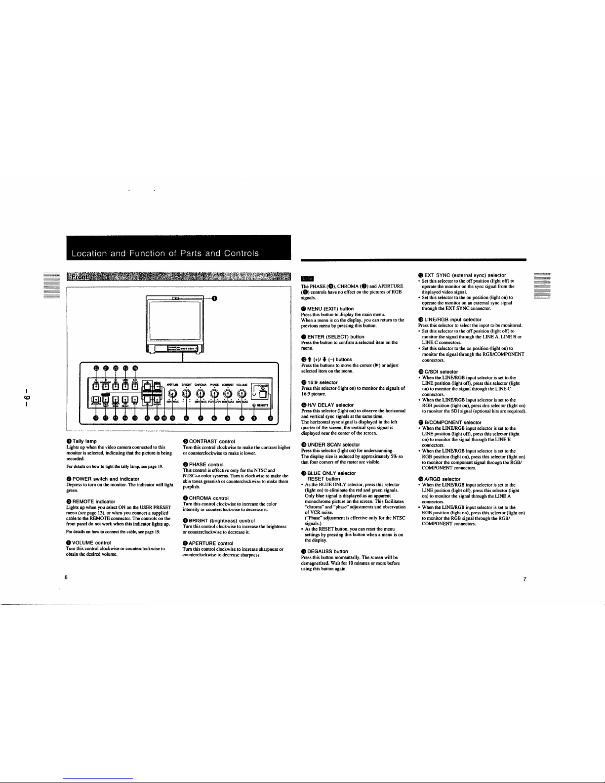
0Tally lamp
Lights up when the video camera connected to this
monitor is selected, indicating that the picture is being
recorded.
For details on how to light the tally lamp, see page 19.
8 POWER switch and indicator
Depress to tum on the monitor. The indicator will light
green.
8 REMOTE indicator
Lights up when you select ON on the USER PRESET
menu (see page 13), or when you connect a supplied
cable to the REMOTE connector. The controls on the
front panel do not work when this indicator lights up.
For details on how to connect the cable, see page 19.
0 VOLUME control
Tum this control clockwise or counterclockwise to
obtain the desired volume.
6
8 CONTRAST control
Tum this control clockwise to make the contrast higher
or counterclockwise to make it lower.
C, PHASE control
This control is effective only for the NTSC and
NTSCw color systems. Tum it clockwise to make the
skin tones greenish or counterclockwise to make them
purplish.
8 CHROMA control
Tum this control clockwise to increase the color
intensity or counterclockwise to decrease it.
0 BRIGHT (brightness) control
Tum this control clockwise to increase the brightness
or counterclockwise to decrease it.
Ci) APERTURE control
Tum this control clockwise to increase sharpness or
counterclockwise to decrease sharpness.
-
The PHASE (0). CHROMA (8) and APERTURE
(Ci)) controls have no effect on the pictures of ROB
signals.
GI MENU (EXIT) button
Press this button to display the main menu.
When a menu is on the display, you can return to the
previous menu by pressing this button.
CD ENTER (SELECT) button
Press the button to confirm a selected item on the
menu.
8 t (+)/
♦
(-) buttons
Press the buttons to move the cursor (
►)
or adjust
selected item on the menu.
G) 16:9 selector
Press this selector (light on) to monitor the signals of
16:9 picture.
CD HN DELAY selector
Press this selector (light on) to observe the horizontal
and vertical sync signals at the same time.
The horizontal sync signal is displayed in the left
quarter of the screen; the vertical sync signal is
displayed near the center of the screen.
$ UNDER SCAN selector
Press this selector (light on) for underscanning.
The display size is reduced by approximately 5% so
that four comers of the raster are visible.
GI BLUE ONLY selector
RESET button
• As the BLUE ONLY selector, press this selector
(light on) to eliminate the red and green signals.
Only blue signal is displayed as an apparent
monochrome picture on the screen. This facilitates
"chroma" and "phase" adjustments and observation
of VCR noise.
("Phase" adjustment is effective only for the NTSC
signals.)
• As the RESET bunon, you can reset the menu
sellings by pressing this bunon when a menu is on
the display.
f8 DEGAUSS button
Press this bunon momentarily. The screen will be
demagnetized. Wait for IO minutes or more before
using this button again.
GI EXT SYNC (external sync) selector
• Set this selector to the off position (light off) to
operate the monitor on the sync signal from the
displayed video signal.
• Set this selector to the on position (light on) to
operate the monitor on an external sync signal
through the EXT SYNC connector.
GI LINE/RGB input selector
Press this selector to select the input to be monitored.
• Set this selector to the off position (light off) to
monitor the signal through the LINE A, LINE B or
LINE C connectors.
• Set this selector to the on position (light on) to
monitor the signal through the ROB/COMPONENT
connectors.
9 C/SDI selector
• When the LINE/ROB input selector is set to the
LINE position (light off), press this selector (light
on) to monitor the signal through the LINE C
connectors.
• When the LINE/ROB input selector is set to the
ROB position (light on), press this selector (light on)
to monitor the SDI signal (optional kits are required).
&, B/COMPONENT selector
• When the LINE/ROB input selector is set to the
LINE position (light off), press this selector (light
on) to monitor the signal through the LINE B
connectors.
• When the LINE/ROB input selector is set to the
ROB position (light on), press this selector (light on)
to monitor the component signal through the ROB/
COMPONENT connectors.
fi A/RGB selector
• When the LINE/ROB input selector is set to the
LINE position (light off), press this selector (light
on) to monitor the signal through the LINE A
connectors.
• When the LINE/ROB input selector is set to the
ROB position (light on), press this selector (light on)
to monitor the ROB signal through the ROB/
COMPONENT connectors.
7
....
0
I
Location and Function of Parts and Controls
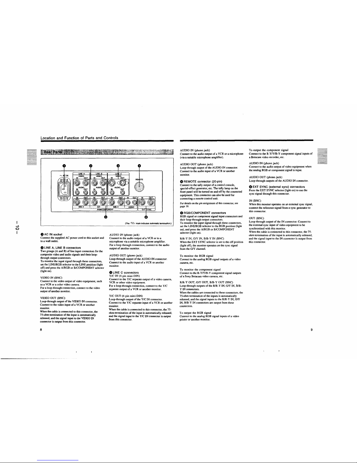
0 AC IN socket
Connect the supplied AC power cord to this socket and
to a wall outlet.
8 LINE A, LINE B connectors
Two groups (A and B) of line input connectors for the
composite video and audio signals and their loopthrough output connectors.
To monitor the input signal through these connectors,
set the LINFJRGB selector to the LINE position (light
off) and press the A/RGB or BICOMPONENT selector
(light on).
VIDEO IN (BNC)
Connect to the video output of video equipment, such
as a VCR or a color video camera.
For a loop-through connection, connect to the video
output of another monitor.
VIDEO OUT (BNC)
Loop-through output of the VIDEO IN connector.
Connect to the video input of a VCR or another
monitor.
When the cable is connected to this connector, the
75-ohm termination of the input is automatically
released, and the signal input to the.VIDEO IN
connector is output from this connector.
8
(The ..1\/\r mark Indicates aulomatic tennination.}
AUDIO IN (phono jack)
Connect to the audio output of a VCR or to a
microphone via a suitable microphone amplifier.
For a loop-through connection, connect to the audio
output of another monitor.
AUDIO OUT (phono jack)
Loop-through output of the AUDIO IN connector.
Connect to the audio input of a VCR or another
monitor.
9 LINE C connectors
YIC IN (4-pin mini-DIN)
Connect to the Y IC separate output of a video camera,
VCR or other video equipment.
For a loop-through connection, connect to the Y IC
separate output of a VCR or another monitor.
YIC OUT (4-pin mini-DIN)
Loop-through output of the Y IC IN connector.
Connect to the YIC separate input of a VCR or another
monitor.
When the cable is connected to this connector, the 75ohm termination of the input is automatically released,
and the signal input to the Y IC IN connector is output
from this connector.
AUDIO IN (phono jack)
Connect to the audio output of a VCR or a microphone
(via a suitable microphone amplifier).
AUDIO OUT (phono jack)
Loop-through output of the AUDIO IN connector.
Connect to the audio input of a VCR or another
monitor.
O REMOTE connector (20-pin)
Connect to the tally output of a control console,
special-effect generator, etc. The tally lamp on the
front panel will be turned on and off by the connected
equipment. This connector can also be used for
connecting a remote control unit.
For details on the pin assignment of this connector. see
page 19.
C, RGB/COMPONENT connectors
RGB signal or component signal input connectors and
their loop-through output connectors.
To monitor the input signal through these connectors,
set the LINFJRGB selector to the RGB position (light
on), and press the A/RGB or BICOMPONENT
selector (light on).
R/R-Y IN, GIY IN, BIB-YIN (BNC)
When the EXT SYNC selector is set to the off position
(light off), the monitor operates on the sync signal
from the GIY channel.
To monitor the RGB signal
Connect to the analog RGB signal outputs of a video
camera, etc.
To monitor the component signal
Connect to the R-Y/Y/B-Y component signal outputs
of a Sony Betacam video camera, etc.
R/R-Y OUT, GIY OUT, B/B-Y OUT (BNC)
Loop-through outputs of the R/R-Y IN, G/Y IN, BIB-
Y IN connectors.
When the cables are connected to these connectors, the
75-ohm termination of the inputs is automatically
released, and the signal inputs to the R/R-Y IN, G/Y
IN, B/B-Y IN connectors are output from these
connectors.
To output the RGB signal
Connect to the analog RGB signal inputs of a video
printer or another monitor.
To output the component signal
Connect to the R-Y/YIB-Y component signal inputs of
a Betacam video recorder, etc.
AUDIO IN (phono jack)
Connect to the audio output of video equipment when
the analog RGB or component signal is input.
AUDIO OUT (phono jack)
Loop-through outputs of the AUDIO IN connector.
0 EXT SYNC (external sync) connectors
Press the EXT SYNC selector (light on) to use the
sync signal through this connector.
IN (BNC)
When this monitor operates on an external sync signal,
connect the reference signal from a sync generator to
this connector.
OUT(BNC)
Loop-through output of the IN connector. Connect to
the external sync input of video equipment to be
synchronized with this monitor.
When the cable is con.nected to this connector, the 75ohm termination of the input is automatically released,
and the signal input to the IN connector is output from
this connector.
9
......
......
Using On-Screen Menus
You can make various settings and adjustments of the monitor using the on-screen menus.
On-screen menu tree-chart
@~Malnmonu
-
-
.
..
10
[iiJST~
"-· ....
.:GI.GJlaWllfOI lffllC _,_ 011
-lltll'ff,L .. Tl
lff9CNT ... LUII.. J.I
- -
tll ,_ a,,
- -
t
f2iiST~ATUS2menu
-
-
-
-
&
13]cHROIIA SET UP menu
EJ
.
-
@cOLOR TEMP/BAL menu
-·
-·
jt,].:::
(5JCAPTIONEJVISIONmenu"
'
'
-
.
.
~
Wi)USER~CONFIG 1 menu
.
.
-
.
- ..
t
lliii!USEE]R CONAG2 menu
-
'
'
-
-
..
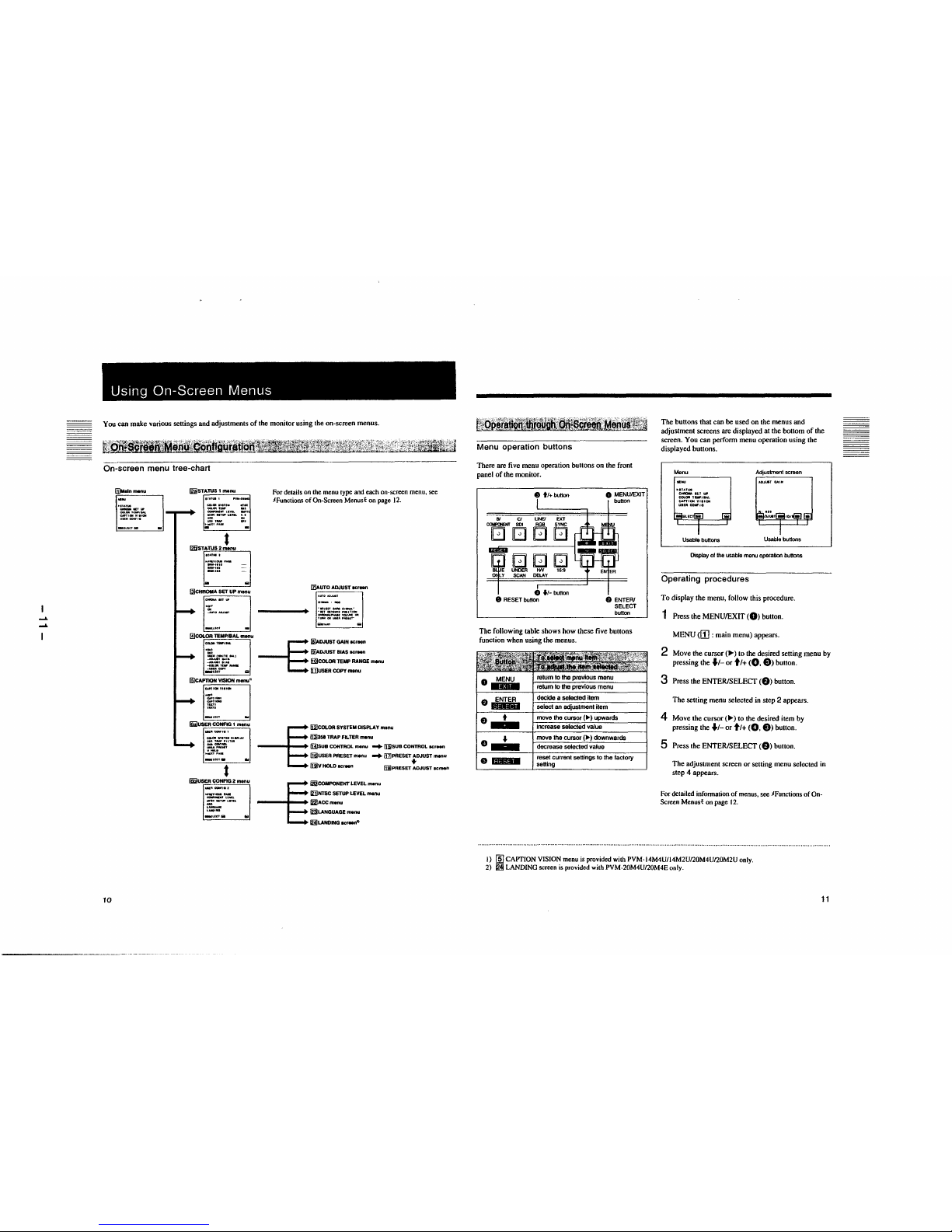
For details on the menu type and each on-screen menu, see
JFunctions of On-Screen Menust on page 12.
Iz)AUTO ADJUST acrean
. .,_llCT-11-.•
... , Nflllfl NalflQN
__ VQ....._OII
I .... GN ... 111, .. NT"
--§
18]AOJUSTGAINIC,_,
(s}ADJUST BIAS IICrNn
liil)COLOR TEMP RANGE SNnu
[i)USER COPY menu
--§
li2)COLOR SYSTEM DISPLAY menu
fl31351 TRAP FILTER m•nu
(HJsua CONTROL menu -+ II5}SUB CONTROL "'""
ffii!USER PRESET m•nu -+ 11z]PRESET .JUST menu
~y HOLD •crNn fiB!PRESET ADJUST acraen
--§
/&COMPONENT LEVEL menu
121]NTSC SETUP LEVEL menu
~ACCmenu
~LANGUAGE menu
lijLANOING scf"Nfl">
i,.:•· ... ;.,\',;\',~. si¼~Wlf:4'.t-~z~~i·"1,:, ... i,•··••:¾:l'.¥;J
lf.iQl)§!:IJJi!l'l W!!;.~;,i .. t..~~~l!O§, ... fi'
Menu operation buttons
There are five menu operation buttons on the front
panel of the monitor.
8 tt+button
Bl Cl LINE/ EXT
COIFCIENT SOI RGB SYNC
□□□□
□□□
UNDER tW 16:9
SCAN DELAY
0 ft-button
8 RESET button
0 MENU/EXIT
button
f) ENTER/
SELECT
button
The following table shows how these five buttons
function when using the menus.
ENTER
·--
·--
•
.,_
·-
return to the previous menu
decide a selected item
select an adjustment item
move the cursor
(
►)
upwards
increase selected value
move the
cursor(
►)
downwards
decrease selected value
reset current settings to the factory
setting
The buttons that can be used on the menus and
adjustment screens are displayed at the bottom of the
screen. You can perform menu operation using the
displayed buttons.
Menu
►
IU.TW
~IUUfl
COI.OIITEWJHL
::·:.:::•o.
Usable buttons
Adjustment screen
Usable buttons
Display of the usable menu operation buttons
Operating procedures
To display the menu, follow this procedure.
1 Press the MENU/EXIT (0) button.
MENU <II] : main menu) appears.
2 Move the
cursor(
►)
to the desired setting menu by
pressing the fl- or ti+ (0, 8) button.
3 Press the ENTER/SELECT (8) button.
The setting menu selected in step 2 appears.
4 Move the
cursor(
►)
to the desired item by
pressing the fl- or ti+ (0, 8) buuon.
5 Press the ENTER/SELECT (8) button.
The adjustment screen or setting menu selected in
step 4 appears.
For detailed infonnation of menus. see JFunctions of On-
Screen Menust on page 12.
I) (ID CAPTION VISION menu is provided with PVM-14M4U/14M2U/20M4U/20M2U only.
2) ~ LANDING screen is provided with PVM-20M4U/20M4E only.
11
.....
I\)
I
Using On-Screen Menus
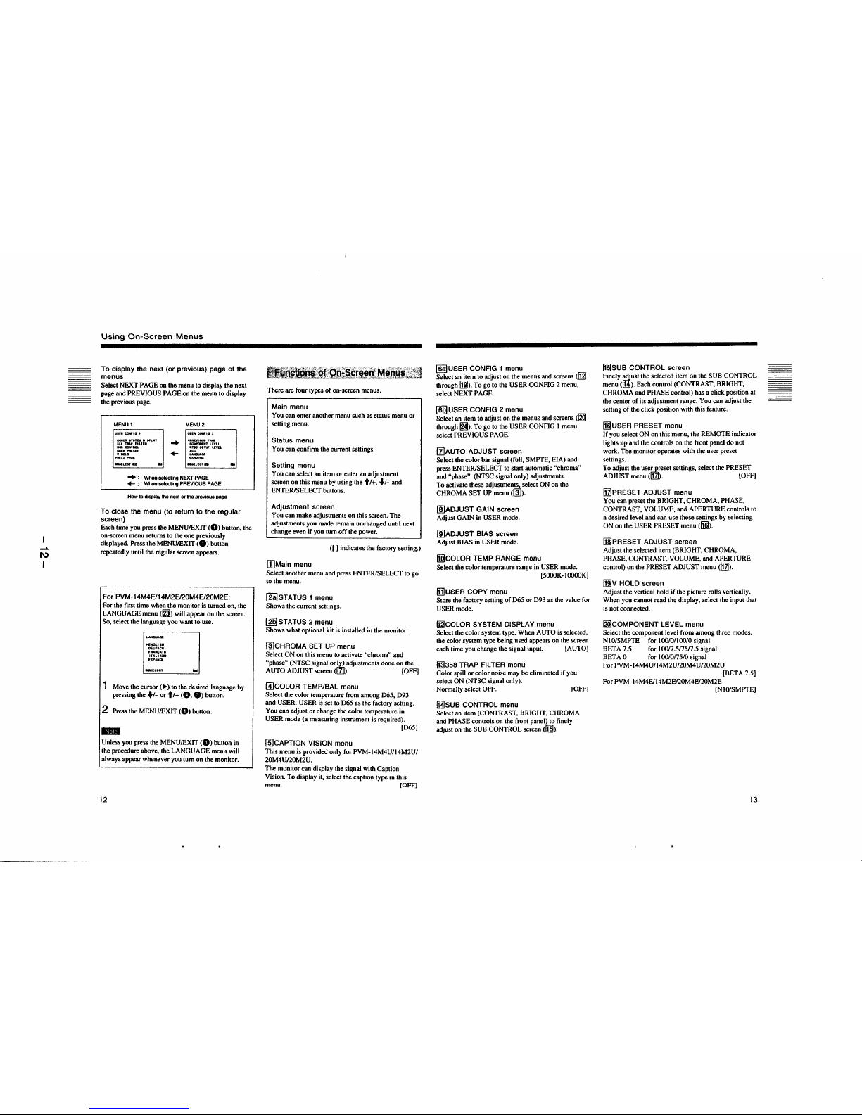
To display the next (or previous) page of the
menus
Select NEXT PAGE on the menu to display the next
page and PREVIOUS PAGE on the menu to display
the previous page.
MENU1
\15IUICC91f1GI
1l0I.Ofl anu.111 DIIWLAY
aHTMl'FILlEIII
,.._..,_
.r.f:::'
..
+-
MENU2
~,'~il
~;TlWLEVEL
-.ucta
-+ : When selecting NEXT PAGE
+- : When selecting PREVIOUS PAGE
How to display the next or the previous page
To close the menu (to return to the regular
screen)
Each time you press the MENU/EXIT (0) button, the
on-screen menu returns to the one previously
displayed. Press the MENU/EXIT (0) button
repeaiedly until the regular screen appears.
For PVM-14M4E/14M2E/20M4E/20M2E:
For the first time when the monitor is turned on, the
LANGUAGE menu (~) will appear on the screen.
So, select the language you want to use.
►
ENGUIH
OEUTSCH
~::~:::
UPMilOL
1 Move the
cursor(
►)
to the desired language by
pressing the
♦
t-
or tt+ (0, 8) button.
2 Press the MENU/EXIT (0) button.
..
Unless you press the MENU/EXIT (0) button in
the procedure above, the LANGUAGE menu will
always appear whenever you tum on the monitor.
12
Blfffl!mi..t:9!~QJi~s§tt@[.t'!1!9irt~=tl
There are four types of on-screen menus.
Main menu
You can enter another menu such as status menu or
setting menu.
Status menu
You can confirm the current settings.
Setting menu
You can select an item or enter an adjustment
screen on this menu by using the tt+,
♦
I-
and
ENTER/SELECT buttons.
Adjustment screen
You can make adjustments on this screen. The
adjustments you made remain unchanged until next
change even if you tum off the power.
([ I indicates the factory setting.)
[)Main menu
Select another menu and press ENTER/SELECT to go
to the menu.
~STATUS 1 menu
Shows the current settings.
(g§STATUS 2 menu
Shows what optional kit is installed in the monitor.
~CHROMA SET UP menu
Select ON on this menu to activate "chroma" and
"phase" (NTSC signal only) adjustments done on the
AUTO ADJUST screen ([z]). [OFF]
@)COLOR TEMP/BAL menu
Select the color temperature from among 065, 093
and USER. USER is set to D65 as the factory setting.
You can adjust or change the color temperature in
USER mode (a measuring instrument is required).
(065]
(IDCAPTION VISION menu
This menu is provided only for PVM-14M4U/14M2U/
20M4Un0M2U.
The monitor can display the signal with Caption
Vision. To display ii, select the caption type in this
menu. [OFF]
@I USER CONFIG 1 menu
Select an item to adjust on the menus and screens (1121
through 11]1). To go to the USER CONFIG 2 menu,
select NEXT PAGE.
(@USER CONFIG 2 menu
Select an item to adjust on the menus and screens (~
through ~)- To go to the USER CONFIG I menu
select PREVIOUS PAGE.
(z]AUTO ADJUST screen
Select the color bar signal (full, SMPTE, EIA) and
press ENTER/SELECT to start automatic "chroma"
and "phase" (NTSC signal only) adjustments.
To activate these adjustments, select ON on the
CHROMA SET UP menu (~).
[IDADJUST GAIN screen
Adjust GAIN in USER mode.
[IDADJUST BIAS screen
Adjust BIAS in USER mode.
!ffiCOLOR TEMP RANGE menu
Select the color temperature range in USER mode.
[5000K-IOOOOKJ
ill]USER COPY menu
Store the factory setting of D65 or D93 as the value for
USER mode.
fl2!COLOR SYSTEM DISPLAY menu
Select the color system type. When AUTO is selected,
the color system type being used appears on the screen
each time you change the signal input. [AUTO]
MJ358 TRAP FIL TEA menu
Color spill or color noise may be eliminated if you
select ON (NTSC signal only).
Normally select OFF. [OFF]
~SUB CONTROL menu
Select an item (CONTRAST, BRIGHT, CHROMA
and PHASE controls on the front panel) to finely
adjust on the SUB CONTROL screen (ff§!).
[§]SUB CONTROL screen
Finely ~ust the selected item on the SUB CONTROL
menu (!HI). Each control (CONTRAST, BRIGHT,
CHROMA and PHASE control) has a click position at
the center of its adjustment range. You can adjust the
setting of the click position with this feature.
[j]!USER PRESET menu
If you select ON on this menu, the REMOTE indicator
lights up and the controls on the front panel do not
work. The monitor operates with the user preset
settings.
To adjust the use!:..l'.reset settings, select the PRESET
ADJUST menu (1111). [OFF)
[z!PRESET ADJUST menu
You can preset the BRIGHT, CHROMA, PHASE,
CONTRAST, VOLUME, and APERTURE controls to
a desired level and can use these settings by selecting
ON on the USER PRESET menu ([§).
il]IPRESET ADJUST screen
Adjust the selected item (BRIGHT, CHROMA,
PHASE, CONTRAST, VOLUME, and APERTURE
control) on the PRESET ADJUST menu ([zl).
jmv HOLD screen
Adjust the vertical hold if the picture rolls vertically.
When you cannot read the display, select the input that
is not connected.
~COMPONENT LEVEL menu
Select the component level from among three modes.
NIO/SMPTE for 100/0/100/0 signal
BET A 7 .5 for I oon .5n5n .5 signal
BETA0 for IOO/0n5/0signal
For PVM-14M4U/14M2U/20M4U/20M2U
[BETA 7.5]
For PVM-14M4E/14M2E/20M4E/20M2E
[N l0/SMPTEJ
13

....
C,,.)
I
Using On-Screen Menus
~NTSC SETUP LEVEL menu
Select the NTSC setup level from two modes.
The 7.5 setup level is mainly used in north America.
The O setup level is mainly used in Europe.
For PVM-l4M4U/l 4M2U/20M4U/20M2U [7 .5)
For PVM-l 4M4E/l 4M2E/20M4E/20M2E [OJ
~ACC menu
Set ACC (Auto Color Control) circuit on or off. When
the fine adjustment is necessary, select OFF on the
ACCmenu.
Normally select ON.
[ON]
~LANGUAGE menu
You can select the menu language from among five
languages (English, German, French, Italian, Spanish).
[ENGLISH)
~LANDING screen
This menu is provided only for PVM-20M4U/20M4E.
If the color is not uniform even after you press the
DEGAUSS button, you can adjust the landing so as to
obtain color uniformity on this screen.
The following two methods are available to adjust the
landing.
When the signals of the horizontal lines are input
and displayed:
Press the
♦
I-
or ti+ button until the lines are
displayed on the screen as horizontally as possible.
When the signals of the white color are input and
displayed:
Press the
♦
1-
or ti+ button until the white color on
the screen become as uniform as possible.
To reset the setting to standard (00), press the
RESET button.
14
Connections
i:~'qJ1fi~9.00llf46Jl1~B~BI
Connect the AC power cord (supplied) to the AC IN
socket and to a wall outlet.
toACtN
to a wall ouUet
~
...
To connect an AC power cord securely
with an AC plug holder
1 AC IN socket
AC plug holder
Plug the power cord into the AC IN socket. Then, attach
the AC plug holder (supplied) on top of the AC power
cord.
2
Slide the AC plug holder over the cord until it locks.
To remove the AC power cord
Pull out the AC plug holder while pressing the lock
levers.
illiiit~M~L~ ~~J2!~9:&C>JJnei<ii_lj
Connect a coaxial cable with the BNC plugs to the
BNC connectors on the rear panel as illustrated below.
L 0<0> Q)
m ~~':':
~~
....
~~
®QQ~~
Insert the BNC plug Into the
connector on lhe rear panel.
matching the slit and pin, and tum
the BNC P,ug clockwise to secure
the connection.
a&
15
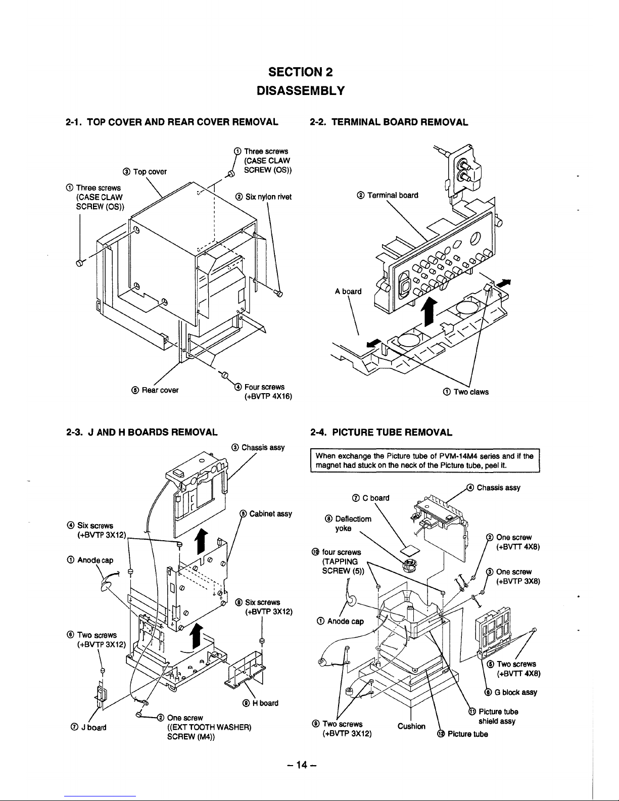
SECTION 2
DISASSEMBLY
2-1. TOP COVER AND REAR COVER REMOVAL 2-2. TERMINAL BOARD REMOVAL
@Top cover
1
Three screws
(CASE CLAW
SCREW (OS))
<D Three screws
(CASE CLAW
SCREW(OS))
_,,c(
,,
1~
@ Rear cover
2-3. J AND H BOARDS REMOVAL
@Six screws
( +BVTP 3X12) r--""'t---::....
' Four screws
(+BVTP 4X16)
@ Chassis assy
A board
\
(D Two claws
2-4. PICTURE TUBE REMOVAL
When exchange the Picture tube of PVM-14M4 series and if the
magnet had stuck on the neck of the Picture tube, peel it.
1
@Two screws
(+BVTT4X8)
-14-
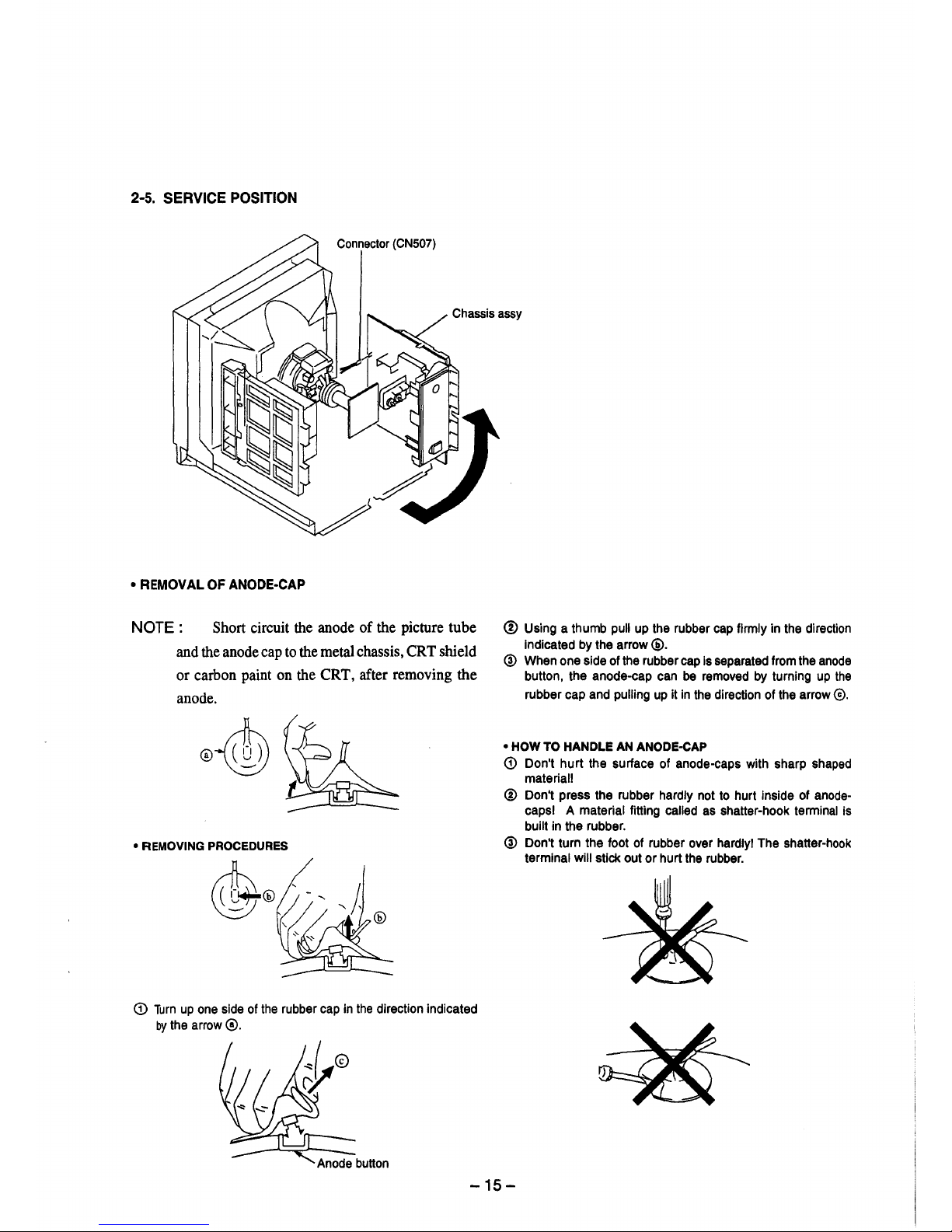
2-5. SERVICE POSITION
Connector (CN507)
Chassis assy
• REMOVAL OF ANODE-CAP
NOTE : Short circuit the anode of the picture tube
and the anode cap to the metal chassis, CRT shield
or carbon paint on the CRT, after removing the
anode.
• REMOVING PROCEDURES
<D Turn up one side of the rubber cap in the direction indicated
by the arrow@.
@ Using a thumb pull up the rubber cap firmly in the direction
Indicated by the arrow @.
@ When one side of the rubber cap is separated from the anode
button, the anode-cap can be removed by turning up the
rubber cap and pulling up it in the direction of the arrow©.
• HOW TO HANDLE AN ANODE-CAP
(D Don't hurt the surface of anode-caps with sharp shaped
material!
® Don't press the rubber hardly not to hurt inside of anode-
capsl A material fitting called as shatter-hook terminal is
built in the rubber.
@ Don't turn the foot of rubber over hardly! The shatter-hook
terminal will stick out or hurt the rubber.
-15-
SECTION 3
SET-UP ADJUSTMENTS
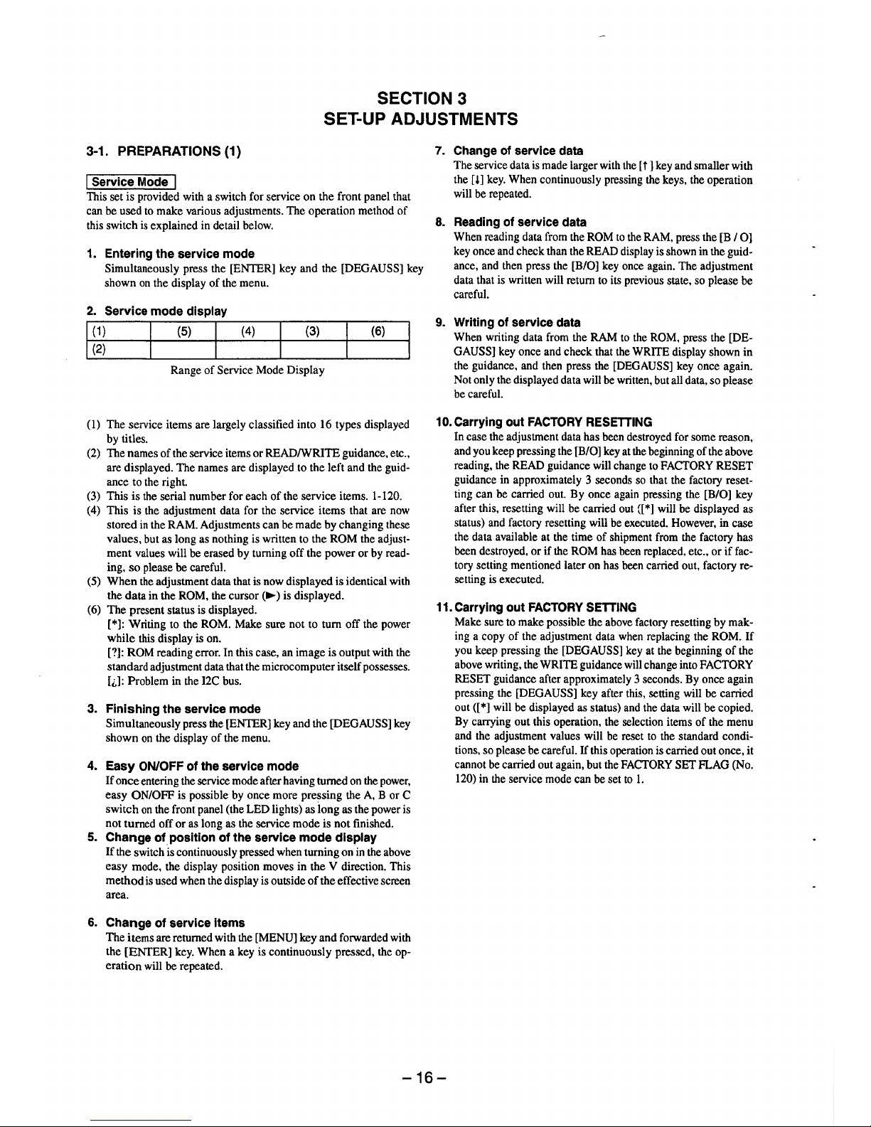
3-1. PREPARATIONS (1)
I Service Mode I
This set is provided with a switch for service on the front panel that
can be used to make various adjustments. The operation method of
this switch is explained in detail below.
1. Entering the service mode
Simultaneously press the [ENTER] key and the [DEGAUSS] key
shown on the display of the menu.
2. Service mode display
I g~ I {S) I
(4)
(3)
(6)
Range of Service Mode Display
(I) The service items are largely classified into 16 types displayed
by titles.
(2) The names of the service items or READ/WRITE guidance, etc.,
are displayed. The names are displayed to the left and the guid-
ance to the right.
(3) This is the serial number for each of the service items. 1-120.
(4) This is the adjustment data for the service items that are now
stored in the RAM. Adjustments can be made by changing these
values, but as long as nothing is written to the ROM the adjust-
ment values will be erased by turning off the power or by read-
ing, so please be careful.
(5) When the adjustment data that is now displayed is identical with
the data in the ROM, the cursor
(
►)
is displayed.
(6) The present status is displayed.
[*]: Writing to the ROM. Make sure not to turn off the power
while this display is on.
[?]: ROM reading error. In this case, an image is output with the
standard adjustment data that the microcomputer itself possesses.
[i,]: Problem in the I2C bus.
3. Finishing the service mode
Simultaneously press the [ENTER] key and the [DEGAUSS] key
shown on the display of the menu.
4. Easy ON/OFF of the service mode
If once entering the service mode after having turned on the power,
easy ON/OFF is possible by once more pressing the A, B or C
switch on the front panel (the LED lights) as long as the power is
not turned off or as long as the service mode is not finished.
5. Change of position of the service mode display
If the switch is continuously pressed when turning on in the above
easy mode, the display position moves in the V direction. This
method is used when the display is outside of the effective screen
area.
6. Change of service items
The items are returned with the [MENU] key and forwarded with
the [ENTER] key. When a key is continuously pressed, the operation will be repeated.
7. Change of service data
The service data is made larger with the [i] key and smaller with
the m key. When continuously pressing the keys, the operation
will be repeated.
8. Reading of service data
When reading data from the ROM to the RAM, press the [B / 0]
key once and check than the READ display is shown in the guidance, and then press the [B/O] key once again. The adjustment
data that is written will return to its previous state, so please be
careful.
9. Writing of service data
When writing data from the RAM to the ROM, press the [DEGAUSS] key once and check that the WRITE display shown in
the guidance, and then press the [DEGAUSS] key once again.
Not only the displayed data will be written, but all data, so please
be careful.
10. Carrying out FACTORY RESETTING
In case the adjustment data has been destroyed for some reason,
and you keep pressing the [B/O] key at the beginning of the above
reading, the READ guidance will change to FACTORY RESET
guidance in approximately 3 seconds so that the factory resetting can be carried out. By once again pressing the [B/O] key
after this, resetting will be carried out {[*] will be displayed as
status) and factory resetting will be executed. However, in case
the data available at the time of shipment from the factory has
been destroyed, or if the ROM has been replaced, etc., or if fac-
tory setting mentioned later on has been carried out, factory resetting is executed.
11. Carrying out FACTORY SETTING
Make sure to make possible the above factory resetting by mak-
ing a copy of the adjustment data when replacing the ROM. If
you keep pressing the [DEGAUSS] key at the beginning of the
above writing, the WRITE guidance will change into FACTORY
RESET guidance after approximately 3 seconds. By once again
pressing the [DEGAUSS] key after this, setting will be carried
out([*] will be displayed as status) and the data will be copied.
By carrying out this operation, the selection items of the menu
and the adjustment values will be reset to the standard conditions, so please be careful. If this operation is carried out once, it
cannot be carried out again, but the FACTORY SET FLAG (No.
120) in the service mode can be set to I.
-16-
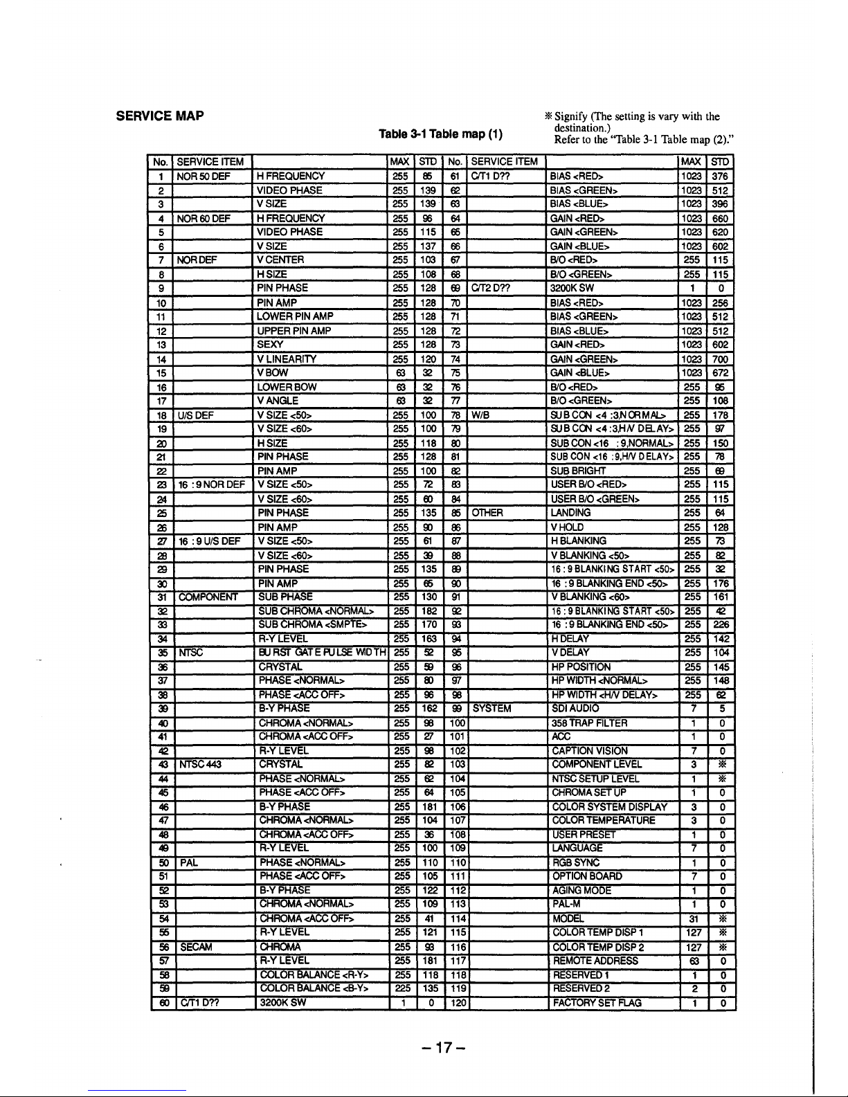
SERVICE MAP
Table 3-1 Table map (1)
No.
SERVICE ITEM
MAX
STD
No. SERVICE ITEM
1
NOR50DEF
HFREQUENCY
255
85 61 C/T1 D??
2
VIDEO PHASE
255
139
62
3
VSIZE 255
139
63
4
NOR60DEF
HFREQUENCY
255 96 64
5
VIDEO PHASE
255
115
65
6
VSIZE
255
137
66
7
NORDEF VCENTER
255
103
ffl
8
HSIZE
255
108
68
9
PIN PHASE 255 128
EB
C/T2D??
10
PIN AMP 255 128 70
11
LOWER PIN AMP
255
128 71
12
UPPER PIN AMP
255
128
7'2
13
SEXY
255
128
73
14
VLINEARITY
255
120
74
15
VBOW
63
32
75
16
LOWERBOW
63
32
76
17
VANGLE
63
32 77
18
UIS DEF VSIZE<50> 255
100
78
W/B
19 VSIZE<60>
255 100
79
a>
HSIZE
255
118
00
21
PIN PHASE
255
128
81
22
PIN AMP 255
100
82
Z3
16 :9NORDEF VSIZE<50> 255
7'2
En
24
VSIZE<60>
255
00 84
25
PIN PHASE
255
135
85
OlHER
26
PIN AMP
255
9)
86
27
16 :9U/SDEF V SIZE<50>
255 61
ffl
28
VSIZE<60> 255 39 88
29
PIN PHASE
255
135
00
~
PIN AMP 255 65
9)
31
COMPONENT SUB PHASE 255
130
91
32
SUB CHROMA <NORMAL> 255 182
~
33
SUB GHROMA <SMPTE>
255
170
00
34
R-YLEVEL 255 163
94
35 NTSC
ElJ AST uAT E PULSE WIDTH
255
~
95
36
CRYSTAL 255
$
96
37
PHASE <NORMAL> 255
00
'Jl
38
PHASE <ACC OFF> 255
96 98
39
B-YPHA::;E
255 162
!B
SYSTEM
40
CHROMA <NORMAL> 255
98
100
41
CHROMA <ACC OFF> 255 27 101
42
R-YLEVEL 255 98 102
43 NTSC443
CRYSTAL 255 82 103
44
PHASE <NORMAL> 255
62
104
45
PHASE <ACC OFF>
255 64 105
46
B-YPHASE
255 181 106
47
CHROMA <NORMAL> 255 104 107
48
liHROMA <ACC OFF>
255 36 108
49
R-YLEVEL 255 100
109
50
PAL PHASE <NORMAL> 255 110 110
51 PHASE <ACC OFF> 255 105 111
~
B-YPHASE
255
122
112
5'3
CHROMA <NORMAL> 255
109
113
54
CHROMA <ACC OFF> 255 41 114
f6
R-YLEVEL 255 121
115
56 SECAM
CHROMA 255
00 116
SI
R-YLEVEL 255 181 117
58
COLOR BALANCE <R·Y> 255 118
118
$ vULOR BALANCE <B-Y>
225
135
119
00 C/T1 D??
3200KSW
1 0 120
-17-
* Signify (The setting is vary with the
destination.)
Refer to the "Table 3-1 Table map (2)."
MAX
STD
BIAS<RED> 1023
376
BIAS <GREEN> 1023
512
BIAS<BLUE>
1023
396
GAIN<RED> 1023
660
GAIN <GREEN>
1023
620
GAIN<BLUE> 1023 602
BIO<RED>
255
115
BIO<GREEN>
255
115
3200KSW 1
0
BIAS<RED>
1023
256
BIAS <GREEN> 1023
512
BIAS<BLUE> 1023 512
GAIN<RED>
1023
602
GAIN <GREEN>
1023
700
GAIN <BLUE>
1023
672
BIO<RED>
255
95
BIO<GREEN> 255 108
SUBC~ <4 :3,NffiMAI.> 255 178
SUBC~ <4:3,HN DaAY> 255
'Jl
SUB CON <16 : 9,NORMAL> 255 150
SUB CON <16 :9,HN DELAY> 255
78
SUB BRIGHT 255
EB
USER B/0 <RED> 255 115
USER B/0 <GREEN> 255 115
LANDING 255
64
VHOLD 255 128
HBLANKING 255
73
V BLANKING <50> 255 82
16: 9 BLANKING START <50> 255 32
16 : 9 BLANKING END <50> 255 176
V BLANKING <60>
255
161
16: 9 BLANKING START <50>
255
42
16 : 9 BLANKING END <50> 255
226
HDELAY
255
142
VDELAY
255 104
HP POSITION
255
145
HP WIDlH <NORMAL> 255 148
HP WIDTH <HN DELAY> 255
62
SDI AUDIO 7
5
358 TRAP FIL TEA 1
0
ACC
1
0
CAPTION VISION 7
0
COMPONENT LEVEL
3
*
NTSC SETUP LEVEL 1
*
CHROMA SET UP
1 0
COLOR SYSTEM DISPLAY
3
0
COLOR TEMPERATURE
3
0
USER PRESET
1 0
LANGUAGE
7
0
RGBSYNC
1
0
OPTION BOARD
7
0
AGING MODE
1
0
PAL-M
1
0
MODEL
31
*
COLOR TEMP DISP 1
127
*
COLOR TEMP DISP 2 127
*
REMOTE ADDRESS
63
0
RESERVED1
1 0
RESERVED2
2
0
FACTORY SET FLAG
1 0
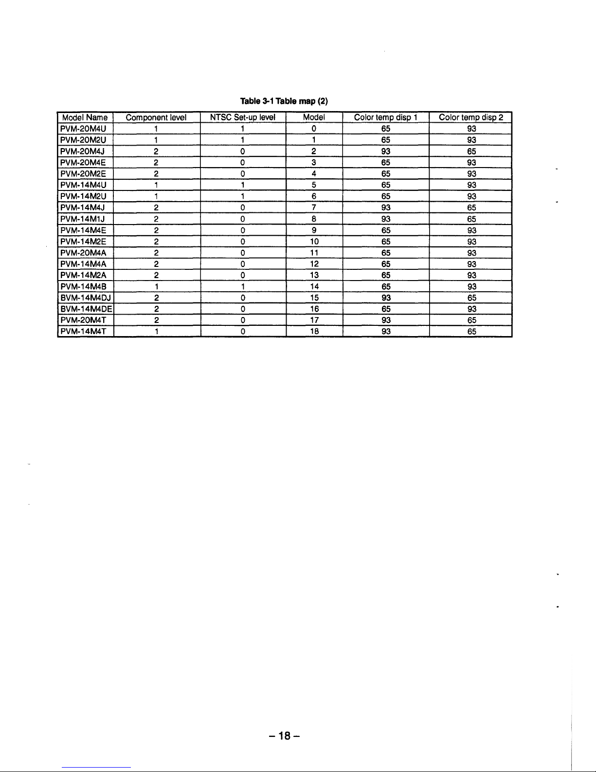
Table 3-1 Table map (2)
Model Name Component level
NTSC Set-up level
Model
Color temp disp 1 Color temp disp 2
PVM-20M4U 1 1 0 65 93
PVM-20M2U
1
1 1
65 93
PVM-20M4J 2 0
2
93 65
PVM-20M4E
2
0 3 65
93
PVM-20M2E 2
0
4
65 93
PVM-14M4U 1 1 5
65 93
PVM-14M2U
1
1
6 65
93
PVM-14M4J
2 0
7
93
65
PVM-14M1J 2 0 8 93
65
PVM-14M4E 2
0
9
65 93
PVM-14M2E
2 0
10
65
93
PVM-20M4A
2 0
11
65
93
PVM-14M4A 2
0
12
65 93
PVM-14M2A 2
0
13
65 93
PVM-14M48
1 1
14
65
93
BVM-14M4DJ
2 0
15
93 65
BVM-14M4DE
2 0
16
65 93
PVM-20M4T
2 0
17
93 65
PVM-14M4T
1 0
18
93
65
-18-
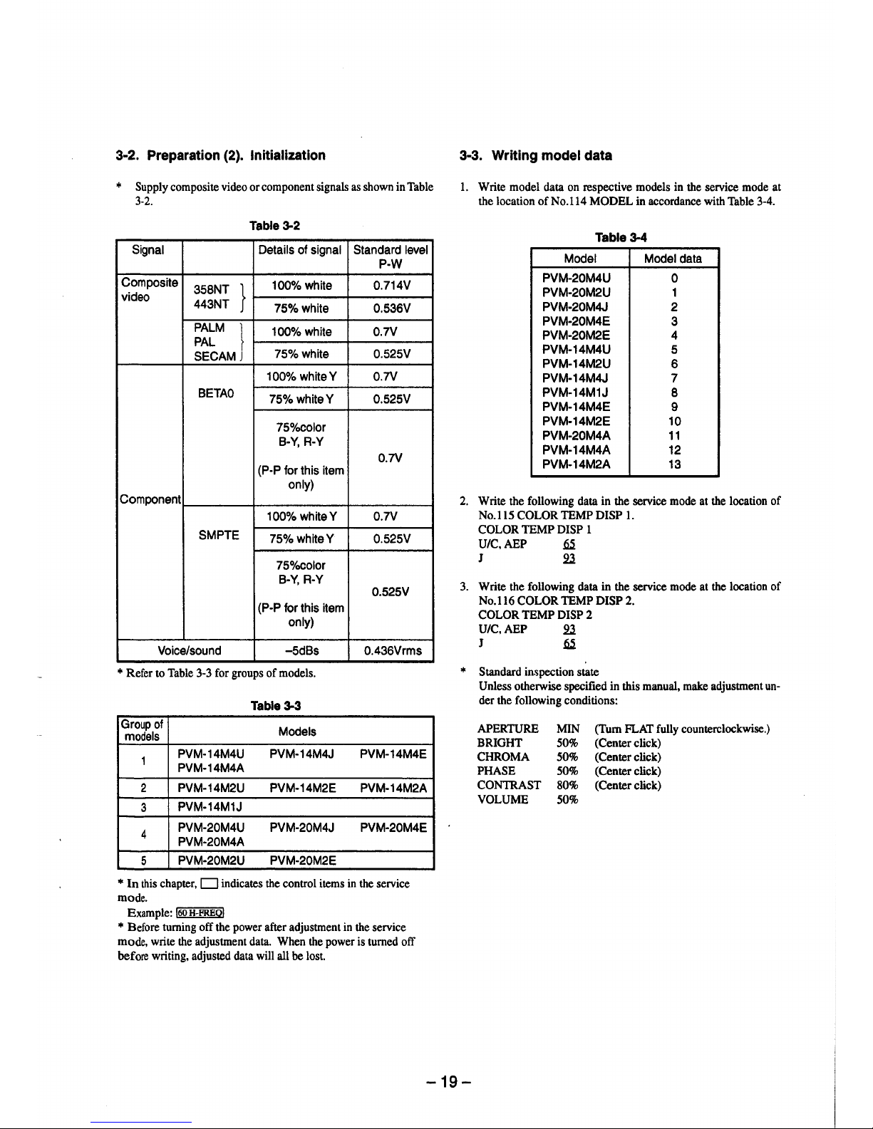
3-2. Preparation (2). Initialization
* Supply composite video or component signals as shown in Table
3-2.
Table3-2
Signal Details of signal Standard level
P-W
Composite
358NT }
100% white 0.714V
video
443NT
75%white 0.536V
PALM }
100% white 0.7V
PAL
SECAM
75%white 0.525V
100% whiteY 0.7V
BETA0
75%whiteY 0.525V
75%color
B-Y, R-Y
0.7V
(P-P for this item
only)
Component
100%whiteY 0.7V
SMPTE
75%whiteY 0.525V
75%color
B-Y, R-Y
0.525V
(P-P for this item
only)
Voice/sound -5dBs 0.436Vrms
* Refer to Table 3-3 for groups of models.
Table 3-3
Group of
Models
models
1
PVM-14M4U PVM-14M4J PVM-14M4E
PVM-14M4A
2 PVM-14M2U PVM-14M2E
PVM-14M2A
3
PVM-14M1J
4
PVM-20M4U PVM-20M4J PVM-20M4E
PVM-20M4A
5
PVM-20M2U PVM-20M2E
* In this chapter, D indicates the control items in the service
mode.
Example: !60 H-FREO!
* Before turning off the power after adjustment in the service
mode, write the adjustment data. When the power is turned off
before writing, adjusted data will all be lost.
3-3. Writing model data
l. Write model data on respective models in the service mode at
the location ofNo.114 MODEL in accordance with Table 3-4.
Table 3-4
Model Model data
PVM-20M4U
0
PVM-20M2U 1
PVM-20M4J 2
PVM-20M4E
3
PVM-20M2E 4
PVM-14M4U 5
PVM-14M2U
6
PVM-14M4J 7
PVM-14M1J
8
PVM-14M4E
9
PVM-14M2E 10
PVM-20M4A 11
PVM-14M4A 12
PVM-14M2A 13
2. Write the following data in the service mode at the location of
No.115 COLOR TEMP DISP 1.
COLOR TEMP DISP 1
U/C,AEP
~
J 2l
3. Write the following data in the service mode at the location of
No.116 COLOR TEMP DISP 2.
COLOR TEMP DISP 2
U/C,AEP 2l
J
~
* Standard inspection state
Unless otherwise specified in this manual, make adjustment under the following conditions:
APERTURE
BRIGHT
CHROMA
PHASE
CONTRAST
VOLUME
MIN (Tum FLAT fully counterclockwise.)
50% (Center click)
50% (Center click)
50% (Center click)
80% (Center click)
50%
-19-
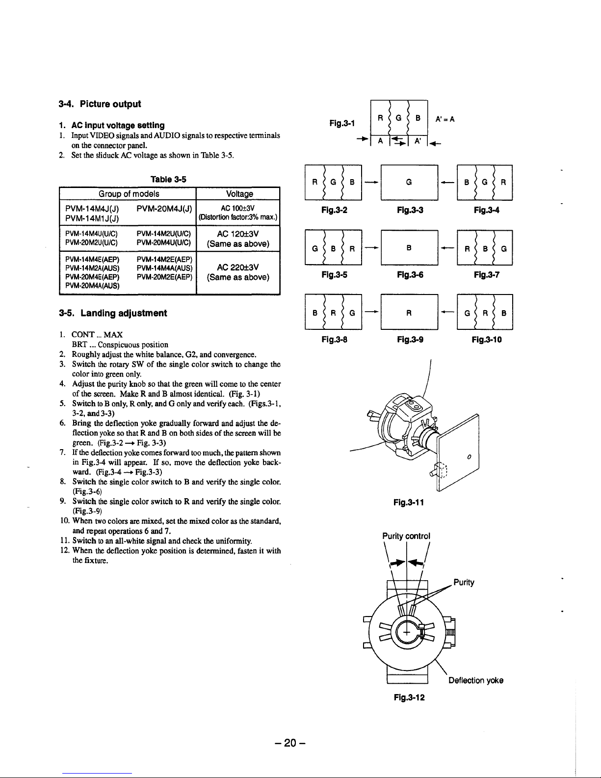
3-4. Picture output
1. AC Input voltage setting
1. Input VIDEO signals and AUDIO signals to respective terminals
on the connector panel.
2. Set the sliduck AC voltage as shown in Table 3-5.
Table 3-5
Group of models Voltage
PVM-14M4J(J) PVM-20M4J(J)
AC 100±3V
PVM-14M1J(J)
(Distortion factor:3% max.)
PVM-14M4U(U/C) PVM-14M2U(U/C)
AC 120±3V
PVM-20M2U(U/C) PVM-20M4U(U/C)
(Same as above)
PVM-14M4E(AEP) PVM-14M2E(AEP)
PVM-14M2A(AUS) PVM-14M4A(AUS)
AC220±3V
PVM-20M4E(AEP) PVM-20M2E(AEP)
(Same as above)
PVM-20M4A(AUS)
3-5. Landing adjustment
1. CONT ... MAX
BRT ... Conspicuous position
2. Roughly adjust the white balance, G2, and convergence.
3. Switch the rotary SW of the single color switch to change the
color into green only.
4. Adjust the purity knob so that the green will come to the center
of the screen. Make R and B almost identical. (Fig. 3-1)
5. Switch to B only, R only, and G only and verify each. (Figs.3-1,
3-2, and 3-3)
6. Bring the deflection yoke gradually forward and adjust the de-
flection yoke so that R and B on both sides of the screen will be
green. (Fig.3-2 - Fig. 3-3)
7. If the deflection yoke comes forward too much, the pattern shown
in Fig.3-4 will appear. If so, move the deflection yoke backward. (Fig.3-4 - Fig.3-3)
8. Switch the single color switch to B and verify the single color.
(Fig.3-6)
9. Switch the single color switch to Rand verify the single color.
(Fig.3-9)
10. When two colors are mixed, set the mixed color as the standard,
and repeat operations 6 and 7.
11. Switch to an all-white signal and check the uniformity.
12. When the deflection yoke position is determined, fasten it with
the fixture.
-20-
Fig.3-1
~
A'=A
~~~
Flg.3-2 Flg.3-3 Fig.3-4
Flg.3-5 Flg.3-6 Flg.3-7
Fig.3-8 Flg.3-9 Flg.3-10
Flg.3-11
Purity control
\~ .. /
Deflection yoke
Flg.3-12
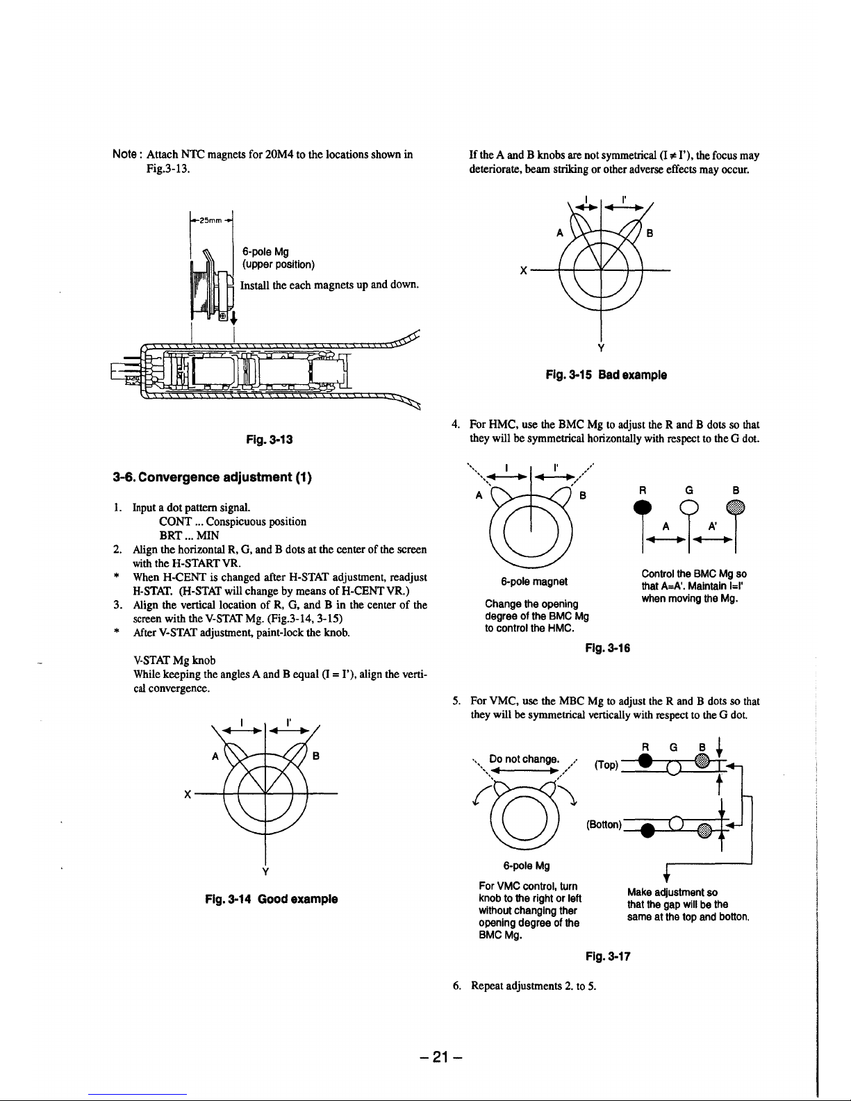
Note : Attach NTC magnets for 20M4 to the locations shown in
Fig.3-13.
6-pole Mg
(upper position)
Install the each magnets up and down.
Flg.3-13
3-6. Convergence adjustment (1}
1. Input a dot pattern signal.
CONT ... Conspicuous position
BRT ... MIN
2. Align the horizontal R, G, and B dots at the center of the screen
with the H-START VR.
* When H-CENT is changed after H-STAT adjustment, readjust
H-STAT. (H-STAT will change by means of H-CENT VR.)
3. Align the vertical location of R, G, and B in the center of the
screen with the V-STAT Mg. (Fig.3-14, 3-15)
* After V-STAT adjustment, paint-lock the knob.
V-STAT Mg knob
While keeping the angles A and B equal (I = I'), align the verti-
cal convergence.
y
Fig. 3-14 Good example
If the A and B knobs are not symmetrical (I ,,ia I'), the focus may
deteriorate, beam striking or other adverse effects may occur.
y
Fig. 3-15 Bad example
4. For HMC, use the BMC Mg to adjust the R and B dots so that
they will be symmetrical horizontally with respect to the G dot.
6-pole magnet
Change the opening
degree of the BMC Mg
to control the HMC.
A G B
T~l~T
Control the BMC Mg so
that A=A'. Maintain l=I'
when moving the Mg.
Flg.3-16
5. For VMC, use the MBC Mg to adjust the R and B dots so that
they will be symmetrical vertically with respect to the G dot.
A G B +
. Do not change. , • A..!..
··•,,◄
~/ (Top) __ -1.Q
~
' , t
'0\~00)~
6-pole Mg
For VMC control, turn
knob to the right or left
without changing ther
opening degree of the
BMC Mg.
Make adjustment so
that the gap will be the
same at the top and botton.
Fig. 3-17
6. Repeat adjustments 2. to 5.
-21-
* The above adjustment may affect the landing, so after adjust•
ment, check the landing again.
7. Paint-lock the knobs after adjustment.
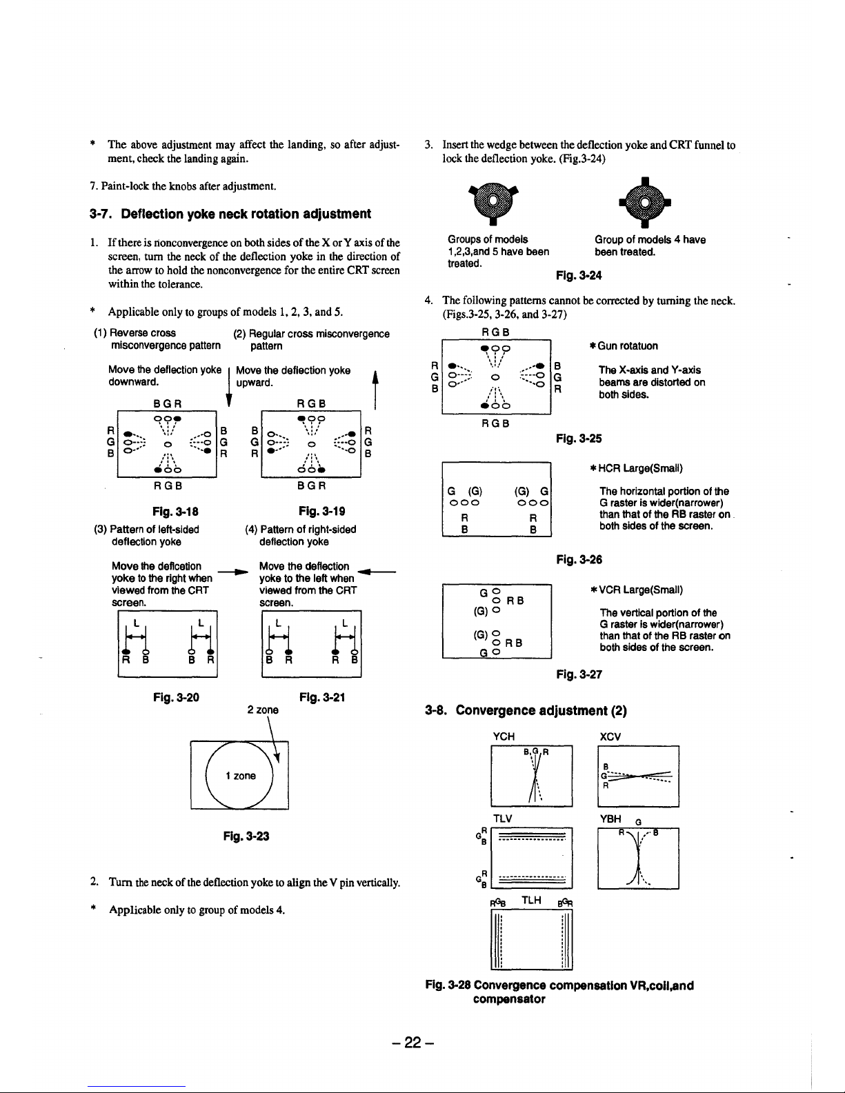
3-7. Deflection yoke neck rotation adjustment
1. If there is lionconvergence on both sides of the X or Y axis of the
screen, turn the neck of the deflection yoke in the direction of
the arrow to hold the nonconvergence for the entire CRT screen
within the tolerance.
* Applicable only to groups of models 1, 2, 3, and 5.
(1) Reverse cross
misconvergence pattern
(2) Regular cross misconvergence
pattern
Move the deflection yoke
~
Move the deflection yoke t
downward. upward.
BGR RGB
R
~?,.
B B
9!,??
R
~:::~
...
:::::; :;:::~
., .
::::~
...
., .
G
0
G
G
0
G
B
o•···
...
·-..•
R R
•····
'"
···-o
B
,': \ ,': \
e6b
oo•
RGB BGR
Fig. 3-18
Fig.3-19
(3) Pattern of left•sided (4) Pattern of right•sided
deflection yoke deflection yoke
Move the deflcetion
~
Move the deflection
~
yoke to the right when yoke to the left when
viewed from the CRT viewed from the CRT
screen.
screen.
H
ti
ti
H
R B B R
B R
R B
Fig. 3-20 Fig. 3-21
2 zone
Fig. 3-23
2. Tum the neck of the deflection yoke to align the V pin vertically.
* Applicable only to group of models 4.
3. Insert the wedge between the deflection yoke and CRT funnel to
lock the deflection yoke. (Fig.3-24)
Groups of models Group of models 4 have
1,2,3,and 5 have been been treated.
treated.
Flg.3-24
4. The following patterns cannot be corrected by turning the neck.
(Figs.3-25, 3·26, and 3-27)
RGB
~??
. ''
'·'-'
0
;,·,
,' : \
eoo
RGB
.•···• B
··•·o G
····-o
R
* Gun rotatuon
The X-axis and Y•axis
beams are distorted on
both sides.
Fig. 3-25
* HCA Large(Small)
G (G)
(G) G The horizontal portion of the
G raster is wider(narrower)
than that of the RB raster on .
both sides of the screen.
000
000
R
B
G g RB
(G)O
(G)g RB
GO
R
B
Fig. 3-26
* VCR Large(Small)
The vertical portion of the
G raster is wider(narrower)
than that of the RB raster on
both sides of the screen.
Fig.3-27
3-8. Convergence adjustment (2)
YCH XCV
rn EJ
a:
□
T·L~·-··········
ITJYBH
0
+
GR •••••••••••••••••. J._
B
~
~
TLH
~
Fig. 3-28 Convergence compensation VR,coil,and
compensator
-22-
Note : When adjustment is insufficient, use permalloy for perfect
adjustment
1. Group of models 4 (See Table 3-3.)
1. Input a cross-hatch signal.
2. Make adjustment with the TLV, YCH, YBH VR, and XCV coils
of the deflection yoke to minimize nonconvergence.
3. When the nonconvergence of the TILT component is included in
the horizontal convergence, make adjustment with the lLH compensator. (Fig.3-28)
2. Groups of models 1, 2, and 3 (See Table 3-3.)
1. Input a cross-hatch signal.
2. Make adjustment with the TLV, YCH VR, and XCY coils of the
deflection yoke to minimize nonconvergence.
3. When the nonconvergence of the TILT component is included
inthe horizontal convergence, insert the lLH compensator into
the deflection yoke for adjustment. (Fig.3-28)
3. Group of models 5 (See Table 3-3.)
1. Input a cross-hatch signal.
2. Make adjustment with the XCV coil of the deflection yoke to
minimize nonconvergence.
3. When the nonconvergence of the TILT component is included in
the vertical convergence, insert the TLV compensator into the
deflection yoke for adjustment. (Fig.3-28)
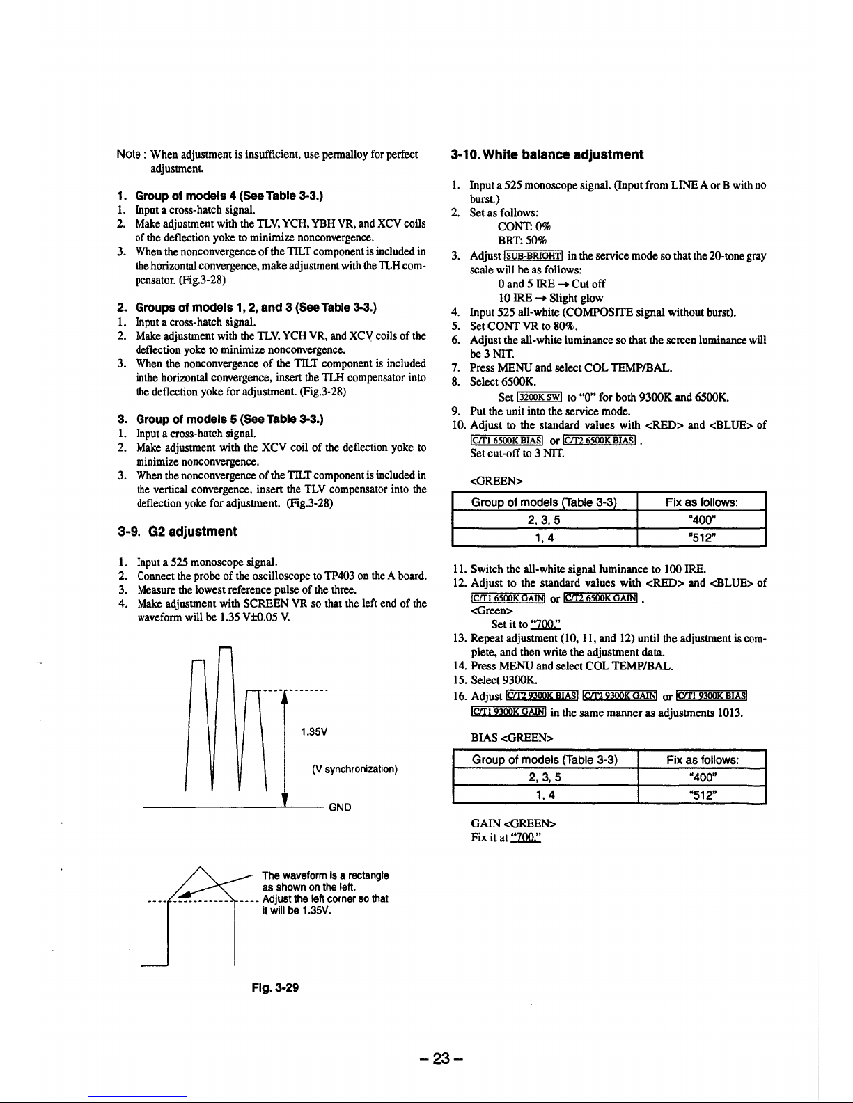
3-9. G2 adjustment
1. Input a 525 monoscope signal.
2. Connect the probe of the oscilloscope to TP403 on the A board.
3. Measure the lowest reference pulse of the three.
4. Make adjustment with SCREEN VR so that the left end of the
waveform will be 1.35 V±0.05 V.
1.35V
(V synchronization)
---------~--GND
The waveform is a rectangle
as shown on the left.
____ Adjust the left corner so that
it will be 1.35V.
Flg.3-29
3-10. White balance adjustment
1. Input a 525 monoscope signal. (Input from LINE A or B with no
burst.)
2. Set as follows:
CONT:0%
BRT:50%
3. Adjust !SUB-BRIGHT! in the service mode so that the 20-tone gray
scale will be as follows:
0 and 5 IRE
➔
Cutoff
10 IRE
➔
Slight glow
4. Input 525 all-white (COMPOSITE signal without burst).
5. Set CONT VR to 80%.
6. Adjust the all-white luminance so that the screen luminance will
be 3 NIT.
7. Press MENU and select COL TEMP/BAL.
8. Select 6500K.
Set i 3200K SW! to "0" for both 9300K and 6500K.
9. Put the unit into the service mode.
10. Adjust to the standard values with <RED> and <BLUE> of
!C/1'1 6500K BIASI or iC/f2 6500K BIAS! •
Set cut-off to 3 NIT.
<GREEN>
Group of models (Table 3-3) Fix as follows:
2,3,5
"400"
1, 4
"512"
11. Switch the all-white signal luminance to 100 IRE.
12. Adjust to the standard values with <RED> and <BLUE> of
iC/1'1 6500K GAIN! or iC/r2 6500K GAIN! •
<Green>
Set it to :ZOO.:
13. Repeat adjustment (10, 11, and 12) until the adjustment is com-
plete, and then write the adjustment data.
14. Press MENU and select COL TEMP/BAL.
15. Select 9300K.
16. Adjust r.:iC/r2="""9300=K;;-B..,I.:-A""'sl 1cm 9300K GAIN! or ictrl 9300K BIASI
ictrl 9300K GAIN! in the same manner as adjustments 1013.
BIAS <GREEN>
Group of models (Table 3-3)
2,3,5
1, 4
GAIN <GREEN>
Fix it at :ZOO.:
Fix as follows:
"400"
"512"
-23-
3-11. Blue-only white balance adjustment
1. Tum ON the blue-only of the user controller SW. (To set blueonly.) ·
2. Input all-white (COMPOSITE signal without burst).
The all-white signal luminance shall be 100 IRE.
CONT:80%
BRT: 50%
3. Select COL TEMP/BAL.
4. Select 6500K.
5. Adjust to the standard values with iCJTI 6500K B/O<RED>! and
jcm 6500K B/O<GREEN>! or !Clf2 6500K B/O<RED> I and
!C/1'1 6500K B/O<GREEN>I .
6. Select COL TEMP/BAL.
7. Select 9300K.
8. Adjust to the standard values with IC/f2 9300K B/O<RED>! and
1cm 9300K B/O<GREEN>! or 1cm 9300K B/O<RED>I and
iC/Tl 9300K B/O<GREEN>I •
9. Adjust the all-white signal luminance, and check that the white
balance is satisfactory when the luminance of the screen is SNIT.
3-12.SUB BRT adjustment
1. Input a 525 monoscope signal.
2. CONT ... MIN
BRT .... CENTER (50&)
3. Select !SUB BRIGHT I in the service mode.
4. Adjust !SUB BRIGHT I so that 10 IRE glows slightly and O IRE is
cut off.
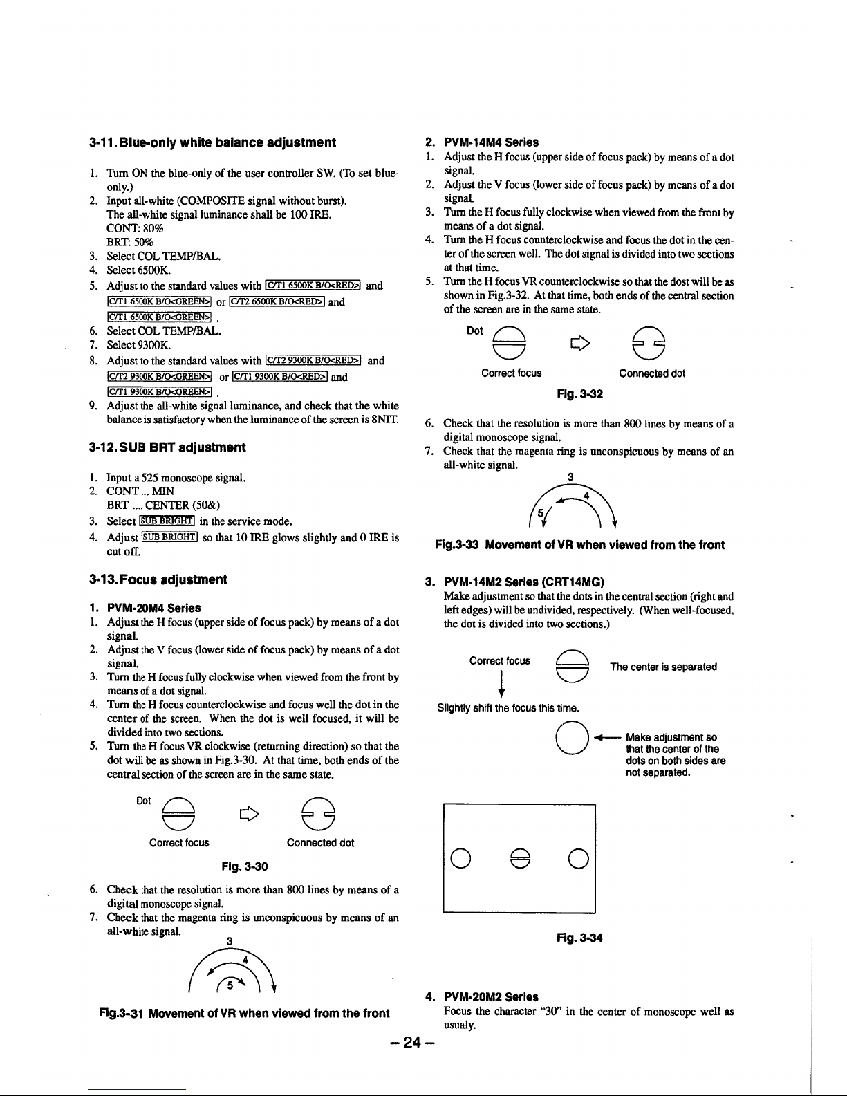
3-13. Focus adjustment
1. PVM-20M4 Serles
1. Adjust the H focus (upper side of focus pack) by means of a dot
signal.
2. Adjust the Y focus (lower side of focus pack) by means of a dot
signal.
3. Tum the H focus fully clockwise when viewed from the front by
means of a dot signal.
4. Tum the H focus counterclockwise and focus well the dot in the
center of the screen. When the dot is well focused, it will be
divided into two sections.
5. Tum the H focus YR clockwise (returning direction) so that the
dot will be as shown in Fig.3-30. At that time, both ends of the
central section of the screen are in the same state.
Dot~
v
Correct focus
Connected dot
Flg.3-30
6. Check that the resolution is more than 800 lines by means of a
digital monoscope signal.
7. Check that the magenta ring is unconspicuous by means of an
all-white signal.
Flg.3-31 Movement of VR when viewed from the front
2. PVM-14M4 Serles
1. Adjust the H focus (upper side of focus pack) by means of a dot
signal.
2. Adjust the V focus (lower side of focus pack) by means of a dot
signal.
3. Tum the H focus fully clockwise when viewed from the front by
means of a dot signal.
4. Tum the H focus counterclockwise and focus the dot in the center of the screen well. The dot signal is divided into two sections
at that time.
5. Tum the H focus YR counterclockwise so that the dost will be as
shown in Fig.3-32. At that time, both ends of the central section
of the screen are in the same state.
Dot~
v
Correct focus
Connected dot
Fig. 3-32
6. Check that the resolution is more than 800 lines by means of a
digital monoscope signal.
7. Check that the magenta ring is unconspicuous by means of an
all-white signal.
3
n
Flg.3-33 Movement of VR when viewed from the front
3. PVM-14M2 Serles {CRT14MG)
Make adjustment so that the dots in the central section (right and
left edges) will be undivided, respectively. (When well-focused,
the dot is divided into two sections.)
Correct focus
The center is separated
Slightly shift the focus this time.
0 e
4. PVM-20M2 Serles
O
,.__ Make adjustment so
that the center of the
dots on both sides are
not separated.
0
Fig.3-34
Focus the character "30" in the center of monoscope well as
usualy.
-24-
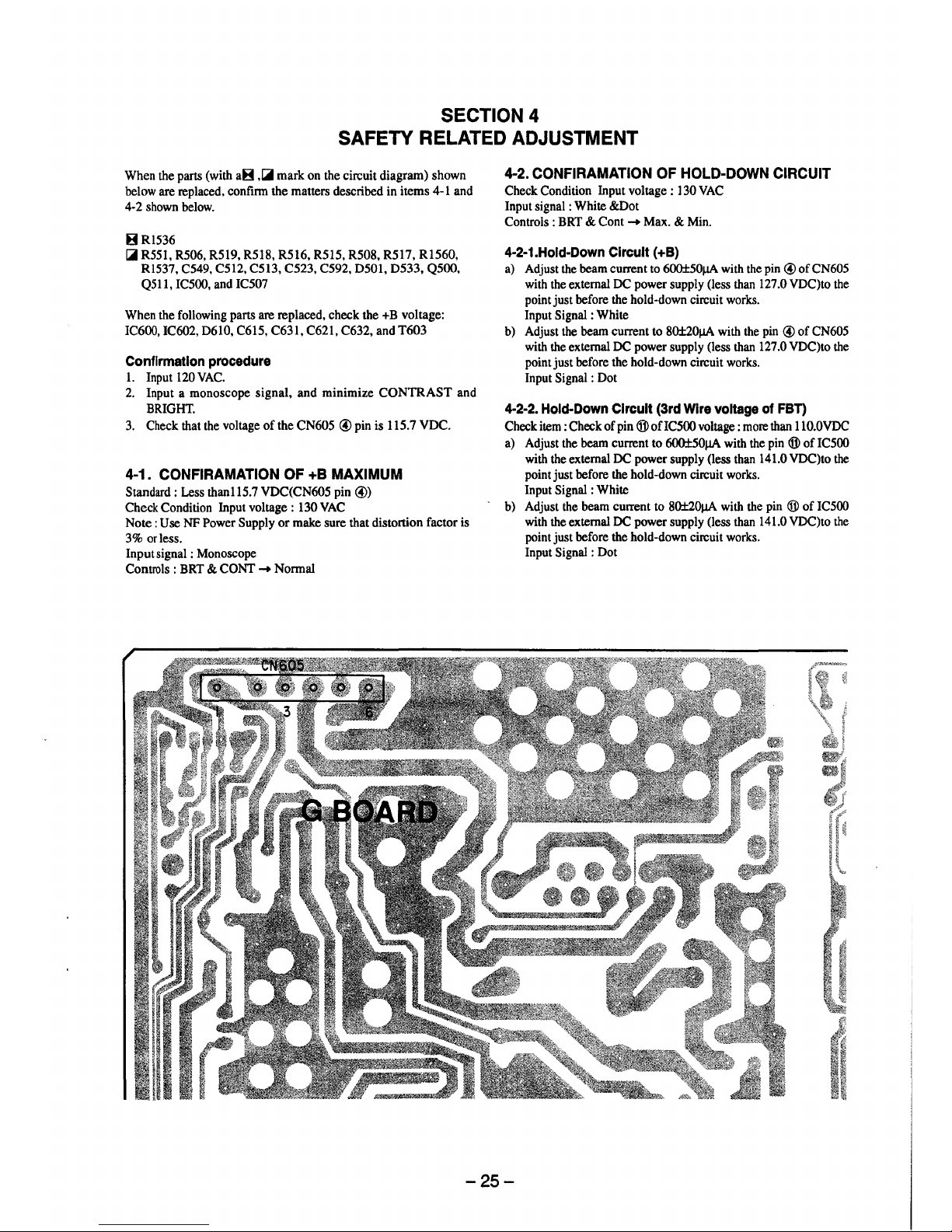
SECTION 4
SAFETY RELATED ADJUSTMENT
When the parts (with aB ,Ci mark on the circuit diagram) shown
below are replaced, confirm the matters described in items 4-1 and
4-2 shown below.
BR1536
Ci R551, R506, R519, R518, R516, R515, R508, R517, R1560,
Rl537, C549, C512, C513, C523, C592, D501, D533, QSOO,
Q511, IC500, and IC507
When the following parts are replaced, check the +B voltage:
IC600, IC602, D610, C615, C631, C621, C632, and T603
Confirmation procedure
I. Input 120 VAC.
2. Input a monoscope signal, and minimize CONTRAST and
BRIGHT.
3. Check that the voltage of the CN605 © pin is 115.7 VDC.
4-1. CONFIRAMATION OF +B MAXIMUM
Standard : Less than115.7 VDC(CN605 pin ©)
Check Condition Input voltage: 130 VAC
Note: Use NF Power Supply or make sure that distortion factor is
3% or less.
Input signal : Monoscope
Controls : BRT & CONT ➔ Normal
4-2. CONFIRAMATION OF HOLD-DOWN CIRCUIT
Check Condition Input voltage : 130 VAC
Input signal : White &Dot
Controls : BRT & Cont ➔ Max. & Min.
4-2-1.Hold-Down Circuit (+B)
a) Adjust the beam current to 600±50µA with the pin © of CN605
with the external DC power supply (less than 127 .0 VDC)to the
point just before the hold-down circuit works.
Input Signal : White
b) Adjust the beam current to 80±20µA with the pin © of CN605
with the external DC power supply (less than 127 .0 VDC)to the
point just before the hold-down circuit works.
Input Signal : Dot
4-2-2. Hold-Down Circuit (3rd Wire voltage of FBT)
Check item : Check of pin ® ofIC500 voltage : more than 110.0VDC
a) Adjust the beam current to 600±50µA with the pin ® of IC500
with the external DC power supply (less than 141.0 VDC)to the
point just before the hold-down circuit works.
Input Signal : White
- b) Adjust the beam current to 80±20µA with the pin ® of IC500
with the external DC power supply (less than 141.0 VDC)to the
point just before the hold-down circuit works.
Input Signal : Dot
-25-
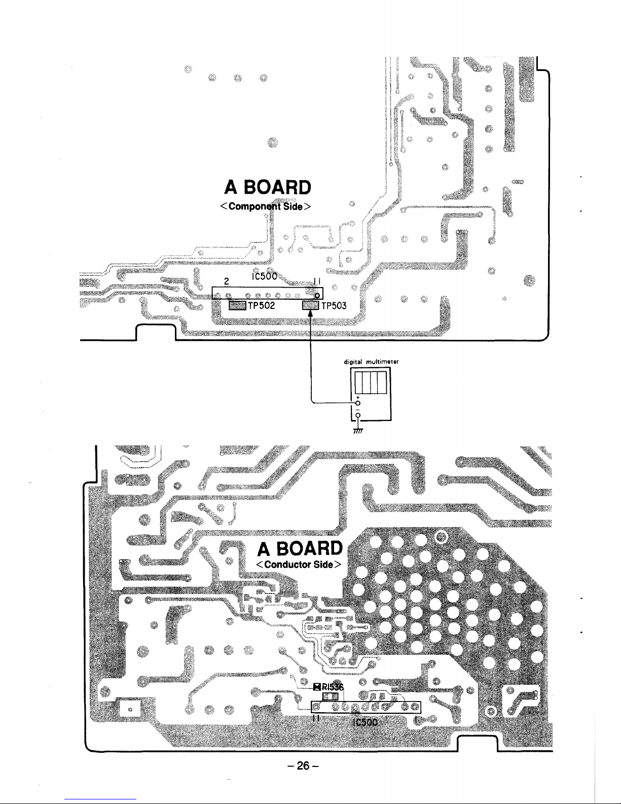
A BOARD
< Compomji't'.:Side >
~--· f?
1t:
digital multimeter
._____E]
i
-26-
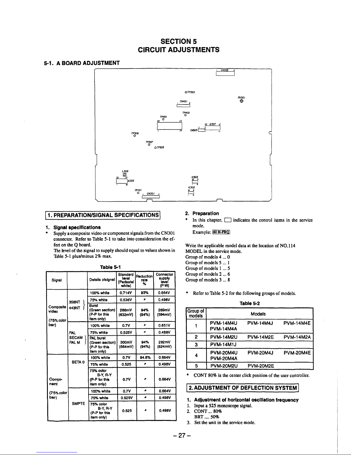
SECTION 5
CIRCUIT ADJUSTMENTS
5-1. A BOARD ADJUSTMENT
TPJ06
0
LJ09
~
µ_.J!,
L__JICJ05
, ,.
TPJ0I
TPXJT
0
TP4C/
0
OTPXJ5
0
1
CNJOI 11
11. PREPARATION/SIGNAL SPECIFICATIONS I
1. Signal specifications
• Supply a composite video or component signals from the CN30 I
connector. Refer to Table 5-1 to take into consideration the effect on the Q board.
The level of the signal to supply should equal to values shown in
Table 5-1 plus/minus 2% max.
Table 5-1
Standard
Reduction
Connector
Signal
Details ofsignal
level
rate
supply
(Pedestal
level
white)
%
(P.W)
100%white
0.714V 93% 0.664V
}
7S°/4 white
0.536V
#
0.498V
358NT
Composite
443NT
Burst
video
(Green section)
286mV
94% 289mV
(P-P for this
(632mV) (94%) (594mV)
(75o/ocolor
item only)
bar)
100%white 0.7V
#
0.651V
PAL
75%white
0.525V
#
0.488V
SECAM}
PAL burst
PALM (Green section)
300mV
94% 282mV
(P•P for this
(664mV)
(94%) (624mV)
item only)
100%white 0.7V
94.8%
0.664V
BETA0
75%whlte 0.525
•
0.498V
75%color
B•Y, R•Y
Compo-
(P-P for this
0.7V
•
0.664V
nent
Item only)
(75%color
100%white
0.7V
•
0.664V
bar)
75%white
0.525V
,,
0.498V
SMPTE
75%color
B-Y, R-Y
0.525
•
0.498V
(P-P for this
item only)
,.
OTPJ00
TP402
0
22 IC507 12
,,~
CN505~
IC50J
□
, 8
IC502
,. 9
CJ
, 8
2. Preparation
CN50J
RV501
@&
• In this chapter, D indicates the control items in the service
mode.
Example: l60H-PRQ!
Write the applicable model data at the location of NO.114
MODEL in the service mode.
Group of models 4 ... 0
Group of models 5 ... 1
Group of models 1 ... 5
Group of models 2 ... 6
Group of models 3 ... 8
• Refer to Table 5-2 for the following groups of models.
Table 5-2
Group of
Models
models
1
PVM-14M4U PVM-14M4J
PVM-14M4E
PVM-14M4A
2
PVM-14M2U PVM-14M2E PVM-14M2A
3
PVM-14M1J
4
PVM-20M4U PVM-20M4J PVM-20M4E
PVM-20M4A
5 PVM-20M2U PVM-20M2E
• CONT 80% is the center click position of the user controller.
12. ADJUSTMENT OF DEFLECTION SYSTEM I
1. Adjustment of horizontal osclllatlon frequency
1. Input a 525 monoscope signal.
2. CONT ... 80%
BRT .... 50%
3. Set the unit in the service mode.
-27-
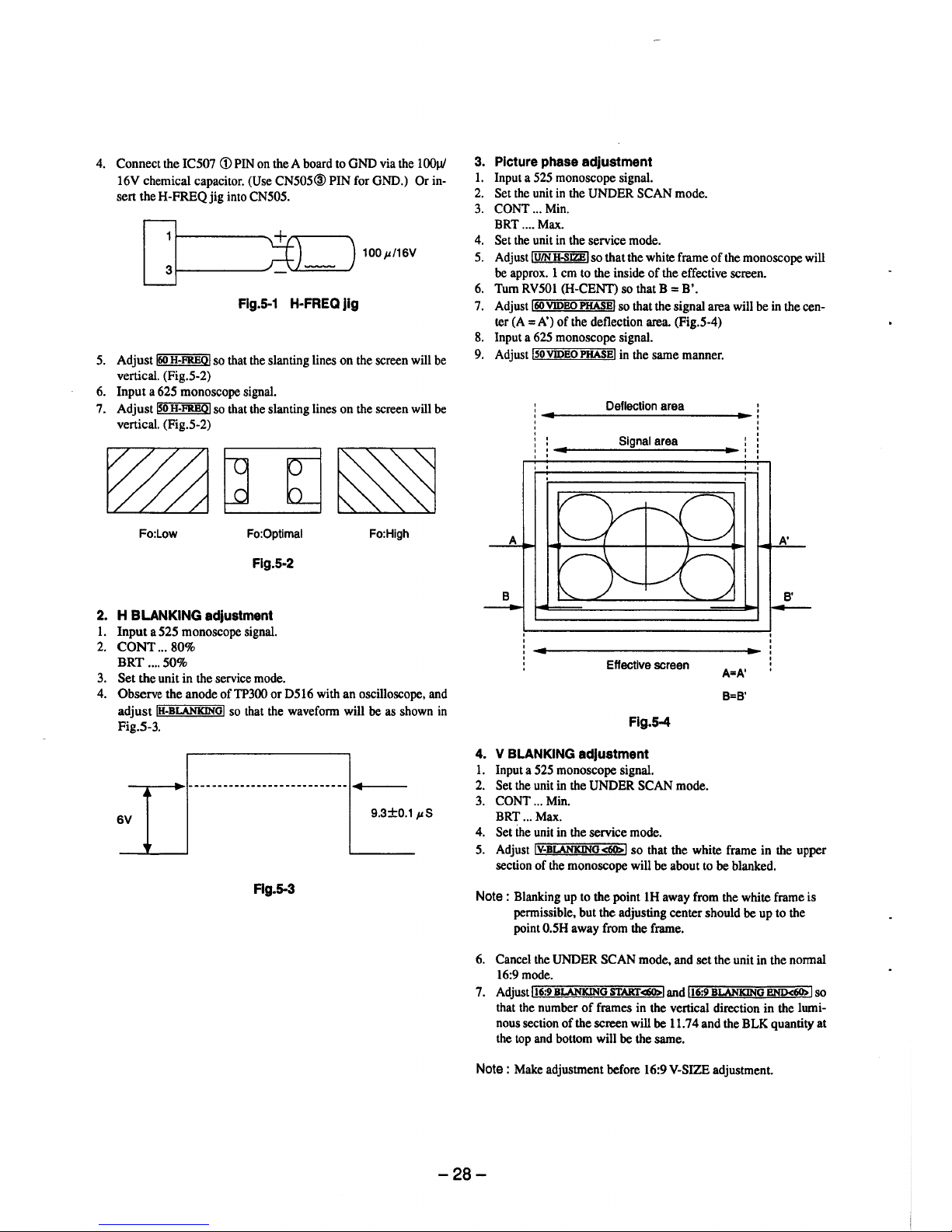
4. Connect the IC507 <D PIN on the A board to GND via the l 00µ/
16V chemical capacitor. (Use CN505@PIN for GND.) Or in-
sert the H-FREQ jig into CN505.
100µ/16V
Flg.5-1 H-FREQ Jig
5. Adjust !60 H-FREOI so that the slanting lines on the screen will be
vertical. (Fig.5-2)
6. Input a 625 monoscope signal.
7. Adjust ~o H-FREOI so that the slanting lines on the screen will be
vertical. (Fig.5-2)
Fo:Low Fo:Optimal
Flg.5-2
2. H BLANKING adjustment
1. Input a 525 monoscope signal.
2. CONT ... 80%
BRT .... 50%
3. Set the unit in the service mode.
Fo:High
4. Observe the anode ofTP300 or D516 with an oscilloscope, and
adjust IH-BLANKINGI so that the waveform will be as shown in
Fig.5-3.
6V
9.3±0.1 µS
Flg.5-3
3. Picture phase adjustment
1. Input a 525 monoscope signal.
2. Set the unit in the UNDER SCAN mode.
3. CONT ... Min.
BRT .... Max.
4. Set the unit in the service mode.
5. Adjust !U/N H-SJZB! so that the white frame of the monoscope will
be approx. 1 cm to the inside of the effective screen.
6. Tum RV501 (H-CENT) so that B = B'.
7. Adjust !60 VIDBO PHASE! so that the signal area will be in the cen-
ter (A= A') of the deflection area. (Fig.5-4)
8. Input a 625 monoscope signal.
9. Adjust !50VIDBOPHASB! in the same manner.
Deflection area
Signal area
Effective screen
Flg.5-4
4. V BLANKING adjustment
1. Input a 525 monoscope signal.
2. Set the unit in the UNDER SCAN mode.
3. CONT ... Min.
BRT ... Max.
4. Set the unit in the service mode.
A=A'
B=B'
A'
B'
---
5. Adjust !V-BLANKINO<60>! so that the white frame in the upper
section of the monoscope will be about to be blanked.
Note : Blanking up to the point lH away from the white frame is
permissible, but the adjusting center should be up to the
point 0.5H away from the frame.
6. Cancel the UNDER SCAN mode, and set the unit in the normal
16:9mode.
7. Adjust !16:9BLANKING START<60>! and !16:9 BLANKING BND<60> I so
that the number of frames in the vertical direction in the luminous section of the screen will be 11. 7 4 and the BLK quantity at
the top and bottom will be the same.
Note : Make adjustment before 16:9 V-SIZE adjustment.
-28-
 Loading...