

Page 1

CAMERA ADAPTOR
HDCA-901
電気製品は、安全のための注意事項を守らないと、火災
警告
このオペレーションマニュアルには、事故を防ぐための重要な注意事項と製
品の取り扱いかたを示してあります。このオペレーションマニュアルをよく
お読みのうえ、製品を安全にお使いください。お読みになったあとは、いつ
でも見られるところに必ず保管してください。
OPERATION MANUAL
や人身事故になることがあり、危険です。
Japanese/English
1st Edition (Revised 1)
Serial No. 10001 and Higher(UCJ)
Serial No. 10101 and Higher(SY)
Page 2
日本語
安全のために
ソニー製品は安全に十分配慮して設計されています。しかし、電気製品は、
安全のための注意事項を守らないと、火災や感電などにより死亡や大けがな
ど人身事故につながることがあり、危険です。
事故を防ぐために次のことを必ずお守りください。
安全のための注意事項を守る
2(JP)〜 3(JP)ページの注意事項をよくお読みください。
定期点検を実施する
長期間安全に使用していただくために、定期点検を実施することをおすすめ
します。点検の内容や費用については、ソニーのサービス担当者または営業
担当者にご相談ください。
故障したら使用を中止する
ソニーのサービス担当者、または営業担当者にご連絡ください。
万一、異常が起きたら
警告表示の意味
このオペレーションマニュアル
および製品では、次のような表
示をしています。表示の内容を
よく理解してから本文をお読み
ください。
危険
この表示の注意事項を守らない
と、火災・感電・破裂などによ
り死亡や大けがになることがあ
ります。
警告
この表示の注意事項を守らない
と、火災や感電などにより死亡
や大けがなど人身事故につなが
ることがあります。
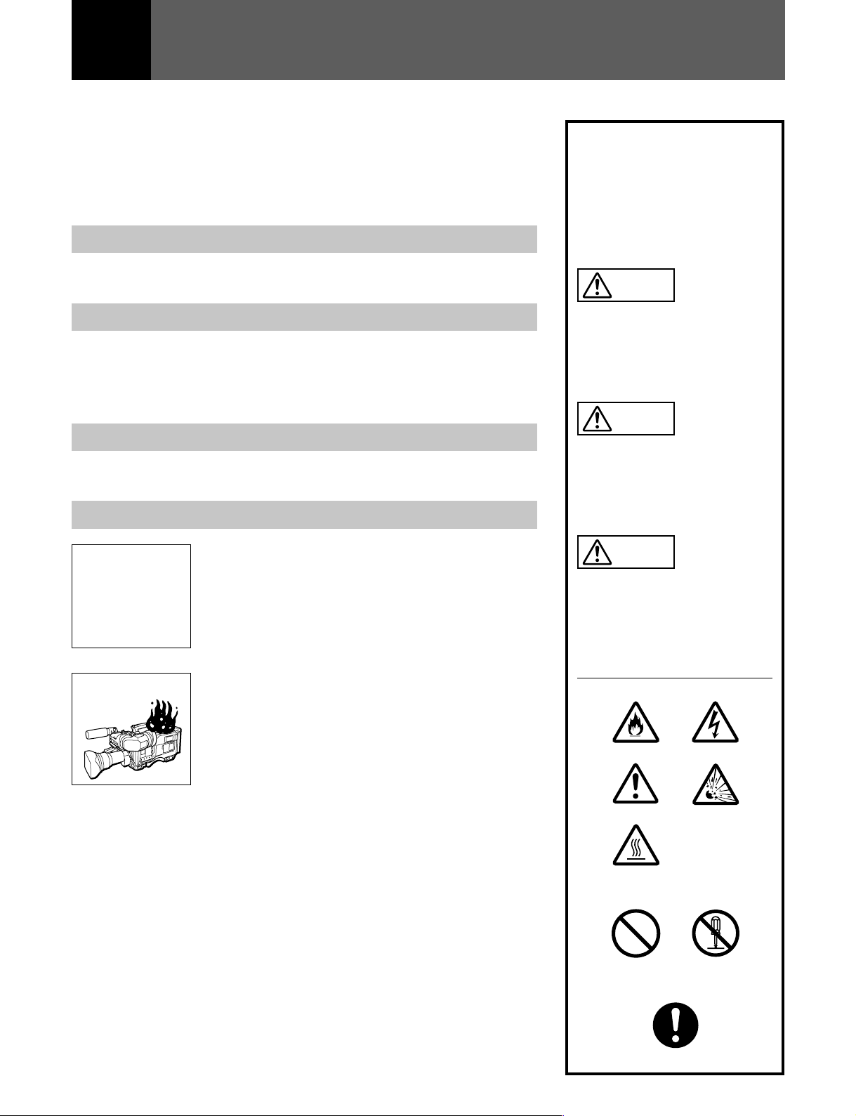
異常な音、に
•
おい、煙が出
たら
落下させたら
•
炎が出たら
1 電源を切る。
/
2 DC電源接続コードを抜く。
3 ソニーのサービス担当者、または営業担当者に
修理を依頼する。
すぐに電源を切り、消火する。
/
注意
この表示の注意事項を守らない
と、感電やその他の事故により
けがをしたり周辺の物品に損害
を与えたりすることがあります。
注意を促す記号
火災
注意
高温
行為を禁止する記号
感電
破裂
禁止
行為を指示する記号
強制
分解禁止
Page 3

目次
警告 ....................................................................................................................
注意 ....................................................................................................................
電池についての安全上のご注意..............................................................................
概要 .........................................................................................................................
各部の名称と働き ...................................................................................................
準備 .........................................................................................................................
HDW-F900への取り付け........................................................................................ 7
HDW-F900の設定.................................................................................................... 7
仕様 .........................................................................................................................
2
2
日
本
語
3
4
5
7
8
1(JP)
Page 4
警告
分解禁止
禁止
禁止
下記の注意を守らないと、
感電火災
火災や感電により死亡や大けがにつながることがあります。
分解しない、改造しない
分解したり、改造したりすると、感電の原因となります。
内部に水や異物を入れない
水や異物が入ると火災や感電の原因となります。
万一、水や異物が入ったときは、すぐに電源を切り、接続コードを抜いて、
ソニーのサービス担当者または営業担当者にご相談ください。
電源ケーブルを傷つけない
DC
DC 電源ケーブルを傷つけると、火災や感電の原因となります。
・ ケーブルを加工したり、傷つけたりしない。
・ 重いものをのせたり、引っ張ったりしない。
・ 熱器具に近づけたり、加熱したりしない。
・ ケーブルを抜くときは、必ずプラグを持って抜く。
万一、ケーブルが傷んだら、ソニーのサービス担当者に交換をご依頼くださ
い。
注意
油煙、湯気、湿気、ほこりの多い場所では設置•使用しない
上記のような場所で設置・使用すると、火災や感電の原因となります。
禁止
下記の注意を守らないと、
けがをしたり周辺の物品に損害を与えることがあります。
固定ねじを締める
カメラと一体化して運用するときは、固定ねじをしっかり締めてください。
固定ねじを締めずに使用するとカメラとカメラアダプターが分離し、落下し
強制
た機器でけがをすることがあります。
2(JP)
Page 5

電池についての安全上のご注意
ここでは、本機での使用が可能なソニー製リチウムイオン電池についての注
意事項を記載しています。
万一、異常が起きたら
・ 煙が出たら
1機器の電源スイッチを切るか、バッテリーチャージャーの電源プラグを
抜く。
2ソニーのサービス担当者に連絡する。
・ 電池の液が目に入ったら
すぐきれいな水で洗い、ただちに医師の治療を受ける。
・ 電池の液が皮膚や衣服に付いたら
すぐにきれいな水で洗い流す。
・ バッテリー収納部内で液が漏れたら
よくふき取ってから、新しい電池を入れる。
下記の注意事項を守らないと、破裂・発火・発熱・液漏れにより、死亡や大
危険
けがになることがあります。
警告
注意
破裂
破裂
高温
高温
・ 充電には、ソニーの専用バッテリーチャージャーを使用する。
充電のしかたについては、バッテリーチャージャーの取扱説明書をよくお
読みください。
・ 火中に投入、加熱、はんだ付けをしない。
・ 分解、改造をしない。
・ 直射日光の当たるところ、炎天下の車内、ストーブのそばなど高温の場所
で、使用・放置・充電をしない。
・ ハンマーでたたくなどの強い衝撃を与えたり、踏みつけたりしない。
・ 接点部や ‘ 極と ’ 極をショートさせたり、金属製のものと一緒に携帯・
保管をしない。
下記の注意事項を守らないと、破裂・発熱・液漏れにより、死亡や大けがな
どの人身事故になることがあります。
・ 所定の充電時間を超えても充電が完了しない場合は、充電をやめる。
・ 電池使用中や充電、保管時に異臭がしたり、発熱・液漏れ・変色・変形な
どがあったときは、すぐに使用や充電をやめ、火気から遠ざける。
下記の注意事項を守らないと、破裂・液漏れにより、けがをしたり周辺の物
品に損害を与えたりすることがあります。
破裂
・ 投げつけない。
・ 電池を使い切ったとき、長期間使わないときは、取り出しておいてくださ
い。
・ 水や海水につけたり、濡らしたりしない。
3(JP)
Page 6

概要
本機は、HDカムコーダーHDW-F900と一体化し、HDW-F900の
オーディオ入力チャンネル(CH1/CH2)と合わせて4チャンネル
(CH1/CH2/CH3/CH4)のオーディオ入力 を可能 にするカ メラアダ
プターです。
本機は以下のような特長を持っています。
HD SDI
2系統のHDTVシリアルデジタルの映像/音声出力コネクターを装
備し、記録画と音声のトー タルなモニターが可能にな り ま した。
出力に対応
豊富なモニター機能
• モニター出力コネクター(XLR型5ピン、ステレオ)とヘッドホン出
力コネクター(標準ジャ ック、 ステレオ)を装備。
• 3/4チャンネルに加え、HDW-F900側の1/2チャンネルのモニ
ター音声出力も、本機側で選択できます。
多様な電源対応
• 本機のDC入力に供給された電源を、HDW-F900側に供給する
ことができます 。
• DC 出力コネク ターから、UHFシンセサイ ザーダイ バーシティー
チューナーWRR-860等への電源を供給できます。
4(JP)
Page 7

各部の名称と働き
1
バッテリー取り付け部
2
PHONES
ジャック
8
9
DC OUT
DC IN
コネクター
コネクター
3
PHONES LEVEL
4
AUDIO IN CH-3/CH-4 LINE/MIC/+48V ON
切り換えスイッチ
5
AUDIO IN CH-3/CH-4
6
AUDIO OUT
7
HD SDI OUT 1/2
つまみ
コネクター
コネクター
コネクター
0
音声チャンネル
!¡
LIGHT
!™
AUDIO LEVEL CH-3/4
!£
AUDIO SELECT CH-3/4
!¢
MONITOR
!∞
POWER
スイッチ
スイッチ
3/4
スイッチ
レベルメーター
つまみ
スイッチ
5(JP)
Page 8

各部の名称と働き
1
バッテリー取り付け部
バッテリーパックBP-L60Aを取り付けます。
◆ バッテリーの取り付け かたについては、HDW-F900のオペレーション
マニュアルを ご覧ください。
!¡
LIGHT(照明)
表示窓の照明をコントロール します。
:照明をつける。
ON
:照明を消す。
OFF
スイッチ
2
PHONES(
インピーダンス8Ωの標準タイプのステレオヘッドホンを接続します。
3
PHONES LEVEL(
PHONESジャックから出力される音量を調整します。
4
AUDIO IN CH-3/CH-4 LINE/MIC/+48V ON(
力チャンネル
AUDIOINCH-3/CH-4コネクターに入力した音声信号の音源を
切り換えます。
:ライ ン入力するオーディオ機器
LINE
:内部電源供給方式のマイク
MIC
+
48V ON
5
AUDIO IN CH-3/CH-4(
(XLR型、3
オーディオ機器やマイクをつなぎ ます。
HDW-F900側のAUDIOCH-1/CH-2コネクターと合わせて4
チャンネルの音声入力が可能です。
ヘッドホン)ジャック
ヘッドホン音量)つまみ
ライン入力/マイク入力)切り換えスイッチ
3/4
:外部電源供給方式のマイク
ピン、メス
音声チャンネル
)
3/4)
音声入
コネクター
!™
AUDIO LEVEL CH-3/4(
つまみ
調整
)
AUDIOSELECTCH-3/4スイッチをMANにすると、これらのつ
まみで音声チャンネル3、4の音声レベルを調整できます。
!£
AUDIO SELECT CH-3/4(
動レベル調整切り換え
音声チャンネル3、4の音声レベル調整方法を選びます。
:自動調整する。
AUTO
MANUAL
!¢
MONITOR
AUDIOOUTコネクターまたはヘッドホンからの音声出力のチャ
ンネルを切り換え ます。本機で 4 チャ ンネルのモニタ ー出力を切
り換えることができます。
はじめに左側のス イッチでCH1/2またはCH3/4を選択し、次に
右側のスイッチでST(CH1/2またはCH3/4のステレオ出力)ま
たはMONO(各チャンネル単独のモノラル出力)を選択します。
:AUDIOLEVELCH-3/4つまみで手動調整する。
スイッチ
スイッチ
)
音声チャンネル
音声チャンネル
録音レベル
3/4
3/4自動/
手
6
AUDIO OUT(
ス
)
MONITORスイッチで選択した音声信号を出力します。
7
HD SDI OUT 1/2
2系統のHDSDIの映像/音声信号を出力します。
8
DC IN(DC
ACアダプターまたは外部バッテリーのDC出力ケーブルを接続し
ます。本機に入力した電源が、HDW-F900にも供給されます。
9
DC OUT(DC
UHFシンセサイザーダイバーシテ ィ ーチューナーWRR-860(別売
り)用の電源を供給します。別売りバッテリ ーとチューナーを取り
付けて使用するとき、HDW-F900後面のDCOUTコネクターに電
源コードが届かない場合、このコネク ター を使用します。
音声チャンネル
0
AUDIOINCH-3/CH-4コネクターに入力した音声信号の入力レ
ベルまたは再生時の再生レベルを表示します。
音声出力)コネクター
コネクター
電源入力)コネクター
電源出力)コネクター(4ピン
レベルメーター
3/4
(BNC型)
(XLR型、4
(XLR型、5
ピン、オ
ピン、オス
)
!∞
POWER(電源)
本機の電源を入/切します。HDSDI出力を使ってモニターしな
い場合は、音声回路のみの電源を入れてパワーセーブすること
もでき ます。
ON ALL
ON SEL
)
OFF
ご注意
本機のPOWERスイッチをONALLまたはONSELに設定してい
るときは、HDW-F900側のPOWERスイッチで本機の電源も入/
切できます。
:すべての電源を入れる。
:HDSDI出力をカットし、音声回路のみの電源を入れ
る。
◆ 音声回路をカ ットし、HDSDI出力のみにすることもできま
す。詳しく は、付属のメンテナンスマニュアルをご覧く ださ
い。
:電源を切る。この状態でも、HDW-F900側のPOWERス
イッチでHDW-F900だけの電源を入れることは可能。
スイッチ
6(JP)
Page 9

準備
HDW-F900
への取り付け
1 ネジ2本を外し、精密ネジ1 本を緩めて、カ バーを取 り外す。
HDW-F900
の後部
ネジ
精密ネジ
カバー
3 ネジを締める。
◆ バッテリ ーパック、 UHFポータブルチューナーの取り付けかたについて
は、HDW-F900のオペレーションマニュアルをご覧ください。
HDW-F900
の設定
ご注意
• 取り外したカバーは保 管しておいてく ださい。
• 本機を取り付けない場合は、カバーを取り外さないでください。
2 HDW-F900後部に本機を取り付ける。
HDW-F900
の後部
HDCA-901
位置決めピン
MAINTENANCEメニューのVTRSETUPの中で、
• PBAUDIOCHを「1/2」に
• AURECCH3/4を「AUTO」に
設定してください。
再生時、 カムコーダーからは1/2 チャンネルの音声が出力されま
す。
記録時、本機の3/4チャンネル入力がそのまま3/4チャンネルに記
録されます。
◆ MAINTENANCEメニューの起動方法については、HDW-F900のメン
テナンスマニュアルをご覧ください。
バッテリー用
コネクター
コネクター
7(JP)
Page 10

仕様
一般
5.0
電源電圧
消費電力 8W
動作温度 0℃〜+40℃
保存温度 −20℃〜+60℃
外形寸法 157×195×65mm(幅×高さ×奥行き)
質量 1.0kg
入出力コネクター
AUDIOINCH-3/4 XLR型3ピン、メス
AUDIOOUT XLR型5ピン、オス、0dBm
DCIN XLR型4ピン、オス、DC11〜17V
DCOUT 4ピン、DC11〜17V、最大定格電流0.1A
HDSDIOUT BNC型、0.8Vp-p、75Ω
+
DC12
−60dBu/+4dBu
V
−1.0
(0dBu=0.775Vrms.)
付属品
オペ レーションマニュアル(1)
メンテナンスマニュアル(1)
別売り品
延長基板 BC-155、EX-410
バッテリーパック BP-L60A
UHFシンセサイザーダイバーシティーチューナー WRR-860
ACアダプター AC-550
レインカバー (サービスパーツ番号:3-188-446-01)
オーディオケーブル CCXA-53
仕様および外観は、改良のため予告なく変更することがあります
が、ご了承ください。
..............................................................................................................................................................................................................................................................
この説明書は再生紙を使用しています。
8(JP)
Page 11

English
WARNING
To prevent fire or shock hazard, do not
expose the unit to rain or moisture.
To avoid electrical shock, do not open
the cabinet. Refer servicing to qualified
personnel only.
AVERTISSEMENT
Afin d’éviter tout risque d’incendie ou
d’électrocution, ne pas exposer cet
appareil à la pluie ou à l’humidité.
Afin d’écarter tour risque d’électrocution,
garder le coffret fermé. Ne confier
l’entretien de l’appareil qu’à un
personnel qualifié.
For the customers in U.S.A.
This equipment has been tested and found to comply with
the limits for a Class A digital device, pursuant to Part 15 of
the FCC Rules. These limits are designed to provide
reasonable protection against harmful interference when
the equipment is operated in a commercial environment.
This equipment generates, uses, and can radiate radio
frequency energy and, if not installed and used in
accordance with the instruction manual, may cause harmful
interference to radio communications. Operation of this
equipment in a residential area is likely to cause harmful
interference in which case the user will be required to
correct the interference at his or her own expense.
You are cautioned that any changes or modifications not
expressly approved in this manual could void your authority
to operate this equipment.
English
For the customers in Europe
This product with the CE marking complies with the EMC
Directive (89/336/EEC) issued by the Commission of the
European Community.
Compliance with this directive implies conformity to the
following European standards:
• EN55103-1: Electromagnetic Interference (Emission)
• EN55103-2: Electromagnetic Susceptibility (Immunity)
This product is intended for use in the following
Electromagnetic Environment(s):
E1 (residential), E2 (commercial and light industrial), E3
(urban outdoors) and E4 (controlled EMC environment, ex.
TV studio).
Pour les clients européens
Ce produit portant la marque CE est conforme à la
Directive sur la compatibilité électromagnétique (EMC) (89/
336/CEE) émise par la Commission de la Communauté
européenne.
La conformité à cette directive implique la conformité aux
normes européennes suivantes:
• EN55103-1: Interférences électromagnétiques (émission)
• EN55103-2: Sensibilité électromagnétique (immunité)
Ce produit est prévu pour être utilisé dans les
environnements électromagnétiques suivants:
E1 (résidentiel), E2 (commercial et industrie légère), E3
(urbain extérieur) et E4 (environnement EMC contrôlé ex.
studio de télévision).
Für Kunden in Europa
Dieses Produkt besitzt die CE-Kennzeichnung und erfüllt
die EMV-Direktive (89/336/EEC) der EG-Kommission.
Die Erfüllung dieser Direktiven bedeutet Konformität für die
folgenden Europäischen Normen:
• EN55103-1: Elektromagnetische Interferenz (Emission)
• EN55103-2: Elektromagnetische Empfindlichkeit
(Immunität)
Dieses Produkt ist für den Einsatz unter folgenden
elektromagnetischen Bedingungen ausgelegt:
E1 (Wohnbereich), E2 (kommerzieller und in beschänktem
Maße Industrieller Bereich), E3 (Stadtbereich im Freien)
und E4 (kontrollierter EMV-Bereich, z.B. Fernsehstudio)
The shielded interface cable recommended in this manual
must be used with this equipment in order to comply with
the limits for a digital device pursuant to Subpart B of Part
15 of FCC Rules.
1(GB)
Page 12

Table of Contents
4-3 Overview
Overview.....................................................................................................3
Locations and Functions of Parts and Controls .....................................4
Preparations...............................................................................................6
Attaching the HDCA-901 to a HDW-F900..........................................6
Settings on the HDW-F900 ..................................................................6
Specifications..............................................................................................7
2(GB)
Page 13

Overview
The HDCA-901 Camera Adaptor attaches to the
HDW-F900 HD Camcorder to provide four channels
of audio input, consisting of two channels on the
HDW-F900 (AUDIO IN CH-1/CH-2 connectors) and
two channels on the HDCA-901 (AUDIO IN CH-3/
CH-4 connectors).
The HDCA-901 has the following features:
HD SDI (Serial Digital Interface) outputs
The HDCA-901 is equipped with two HDTV serial
digital video/audio output connectors to allow full
monitoring of recorded video and audio signals.
Various monitoring functions
•A monitor output connector (XLR type, 5-pin, stereo)
and an headphones output connector (stereo phones
jack) are provided.
•The HDCA-901 can be used to select the audio
output for monitoring from either the AUDIO IN CH1/CH-2 connectors on the HDW-F900 or the AUDIO
IN CH-3/CH-4 connectors on the HDCA-901.
Various power supply capabilities
•Power supplied to the DC IN connector on the
HDCA-901 can be used to power the HDW-F900.
•Power from the DC OUT connector on the HDCA901 can be used to power other equipment such as the
WRR-860A UHF Synthesized Diversity Tuner.
3(GB)
Page 14

Locations and Functions of Parts and Controls
1 Battery attachment
2 PHONES jack
3 PHONES LEVEL control
4 AUDIO IN CH-3/CH-4 LINE/MIC/
+48 V ON switches
5 AUDIO IN CH-3/CH-4 connectors
6 AUDIO OUT connector
7 HD SDI OUT 1/2 connectors
8 DC IN connector
9 DC OUT connector
0 Audio channel 3/4 level meters
!¡ LIGHT switch
!™ AUDIO LEVEL CH-3/4 controls
!£ AUDIO SELECT CH-3/4 switches
!¢ MONITOR switches
!∞ POWER switch
4(GB)
Page 15

1 Battery attachment
Attaches a BP-L60A Battery Pack.
For details on inserting batteries, refer to the Operation
Manual of the HDW-F900.
2 PHONES (headphones) jack
Connects stereo headphones with an impedance of 8
ohms.
0 Audio channel 3/4 level meters
Indicate the level of the signal input to the AUDIO IN
CH-3 and CH-4 connectors or the level of the audio
playback signal.
!¡ LIGHT switch
Turns the display panel illumination on and off.
ON: Turns the illumination on.
OFF: Turns the illumination off.
3 PHONES LEVEL (headphone output level)
control
Adjusts the headphone volume.
4 AUDIO IN CH-3/CH-4 LINE/MIC/+48 V ON
(audio input channel 3/4 line input/microphone
input/external power supply +48 V on) switches
Specifies the audio source or microphone connected to
the AUDIO IN CH-3/CH-4 connectors.
LINE: Line input audio equipment
MIC: A microphone with internal batteries
+48 V ON: A microphone with an external power
supply
5 AUDIO IN CH-3/CH-4 (audio channels 3 and 4)
connectors (XLR type, 3-pin, female)
Connect an audio source or microphone.
Combined with the AUDIO IN CH-1/CH-2 connectors
on the HDW-F900, a total of four audio inputs are
provided.
6 AUDIO OUT (audio output) connector (XLR
type, 5-pin, male)
Outputs the audio signal selected with the MONITOR
switch.
7 HD SDI OUT 1/2 connectors (BNC-type)
Output two channels of HD SDI video/audio signals.
8 DC IN (DC power input) connector (XLR type,
4-pin, male)
Connect an AC adaptor or an external battery through
a DC output cable. Power input to the HDCA-901 is
supplied to the HDW-F900.
9 DC OUT (DC power output) connector (4-pin)
Supplies power to an optional WRR-860A UHF
Synthesized Diversity Tuner. Use this connector when
an optional battery and the tuner are attached to the
HDCA-901 and the tuner’s power cord cannot reach
the DC OUT connector on the rear of the HDW-F900.
!™ AUDIO LEVEL CH-3/4 (audio channel 3/4
recording level) controls
These controls adjust the audio level of channels 3 and
4 when you set the AUDIO SELECT CH-3/4 switches
to MANUAL.
!£ AUDIO SELECT CH-3/4 switches
These switches set the audio level adjustment to
AUTO or MANUAL for channels 3 and 4.
AUTO: Audio level is adjusted automatically.
MANUAL: Audio level is adjusted manually by the
AUDIO LEVEL CH-3 or 4 control.
!¢ MONITOR switches
Select the audio output to the AUDIO OUT connector
or headphones (audio channels 1, 2, 3 or 4).
Use the left switch to select CH 1/2 (audio channels 1
and 2) or CH 3/4 (audio channels 3 and 4), and the
right switch to select ST (two-channel stereo output) or
MONO (single-channel monaural output) for the
selected channels.
!∞ POWER switch
Turns the power to the HDCA-901 on and off. Can be
used to reduce power consumption by supplying power
only to the audio circuits when the output from the HD
SDI circuits is not being monitored.
ON ALL: Supplies power to all circuits.
ON SEL: Supplies power only to the audio circuits,
(power for HD SDI output is cut). Supplying
power only to the HD SDI output circuits while
cutting power to the audio circuits is also possible.
For details, refer to the supplied Maintenance Manual.
OFF: Turns the HDCA-901 off. In this case, the
HDW-F900 can be independently turned on and
off using the POWER switch on the HDW-F900.
Note
When the POWER switch on the HDCA-901 is set to
ON ALL or ON SEL, the POWER switch on the
HDW-F900 controls the power supply to both the
camcorder and camera adaptor at the same time.
5(GB)
Page 16
Preparations
Attaching the HDCA-901 to a
HDW-F900
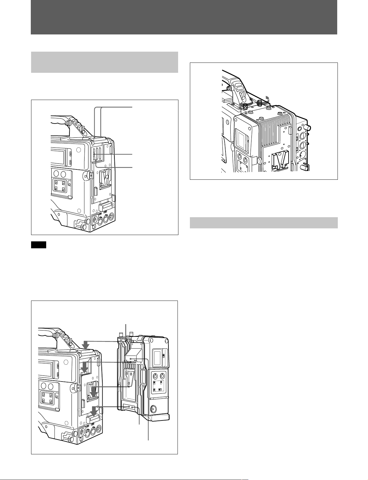
1 Remove the two screws and loosen the precision
screw, and then remove the cover.
Back of the HDW-F900
Screw
Precision screw
Cover
3 Tighten the screws.
For details on attaching a battery pack or UHF portable
tuner to a camcorder with the HDCA-901 attached, refer to
the Operation Manual of the HDW-F900.
Settings on the HDW-F900
Note
•Keep the removed cover.
•When the HDCA-901 is not attached, keep the cover
fixed.
2 Attach the HDCA-901 to the back of the HDW-
F900.
Back of the HDW-F900
Locationing pin
HDCA-901
Activate MAINTENANCE menu on the camcorder
and select the VTR SETUP. Then make the following
settings:
• Set PB AUDIO CH to 1/2
• Set AU REC CH3/4 to AUTO
During the playback, the audio signals of CH1/2 are
output from the camcorder.
During the recording, the audio signals of the AUDIO
IN CH-3/CH-4 connectors on the HDCA-901 are
recorded to CH3/4 as they are.
For details on activating MAINTENANCE menu, refer to the
Maintenance Manual of the HDW-F900.
6(GB)
Battery connector
Connector
Page 17

Specifications
General
Power voltage
Power consumption
Operating temperature
Storage temperature
Dimensions
(6
Mass
+5.0
DC 12
-1.0
8 W
0°C to 40°C (32°F to 104°F)
–20°C to +60°C (–4°F to +140°F)
157 × 195 × 65 mm (w/h/d)
1
/4 × 73/4 × 25/8 inches)
1.0 kg (2 lbs 3 oz)
Input/output connectors
AUDIO IN CH-3/4
XLR-type, 3-pin, female
–60 dBu/+4 dBu
(0 dBu equals 0.775 Vrms)
AUDIO OUT
XLR-type, 5-pin, male
DC IN
XLR-type, 4-pin, male, 11 to 17
V DC
DC OUT
4-pin, 11 to 17 V DC, maximum
current 0.1 A
HD SDI OUT
BNC-type, 0.8 Vp-p, 75 Ω
V
Optional accessories
BC-155, EX-410 Extension Board
BP-L60A Battery Pack
WRR-860A UHF Synthesized
Diversity Tuner
AC-550 AC Adaptor
Rain-proof cover (Part No. 3-188-
446-01)
CCXA-53 Audio Cable
Design and specifications are subject to change
without notice.
Supplied accessories
Operation Manual (1)
Maintenance Manual (1)
..........................................................................................................................................................................................................
Printed on recycled paper
7(GB)
Page 18

Page 19

The material contained in this manual consists of
information that is the property of Sony Corporation and is
intended solely for use by the purchasers of the equipment
described in this manual.
Sony Corporation expressly prohibits the duplication of any
portion of this manual or the use thereof for any purpose
other than the operation or maintenance of the equipment
described in this manual without the express written
permission of Sony Corporation.
Le matériel contenu dans ce manuel consiste en
informations qui sont la propriété de Sony Corporation et
sont destinées exclusivement à l’usage des acquéreurs de
l’équipement décrit dans ce manuel.
Sony Corporation interdit formellement la copie de quelque
partie que ce soit de ce manuel ou son emploi pour tout
autre but que des opérations ou entretiens de l’équipement
à moins d’une permission écrite de Sony Corporation.
Das in dieser Anleitung enthaltene Material besteht aus
Informationen, die Eigentum der Sony Corporation sind,
und ausschließlich zum Gebrauch durch den Käufer der in
dieser Anleitung beschriebenen Ausrüstung bestimmt sind.
Die Sony Corporation untersagt ausdrücklich die
Vervielfältigung jeglicher Teile dieser Anleitung oder den
Gebrauch derselben für irgendeinen anderen Zweck als die
Bedienung oder Wartung der in dieser Anleitung
beschriebenen Ausrüstung ohne ausdrückliche schriftliche
Erlaubnis der Sony Corporation.
Page 20

HDCA-901(SY, , )
3-203-931-02(1)
Sony Corporation
Communication System Solutions Network Company
Printed in Japan
2000.09.13
2000
 Loading...