

Sony HCDZUX-10-D Service manual
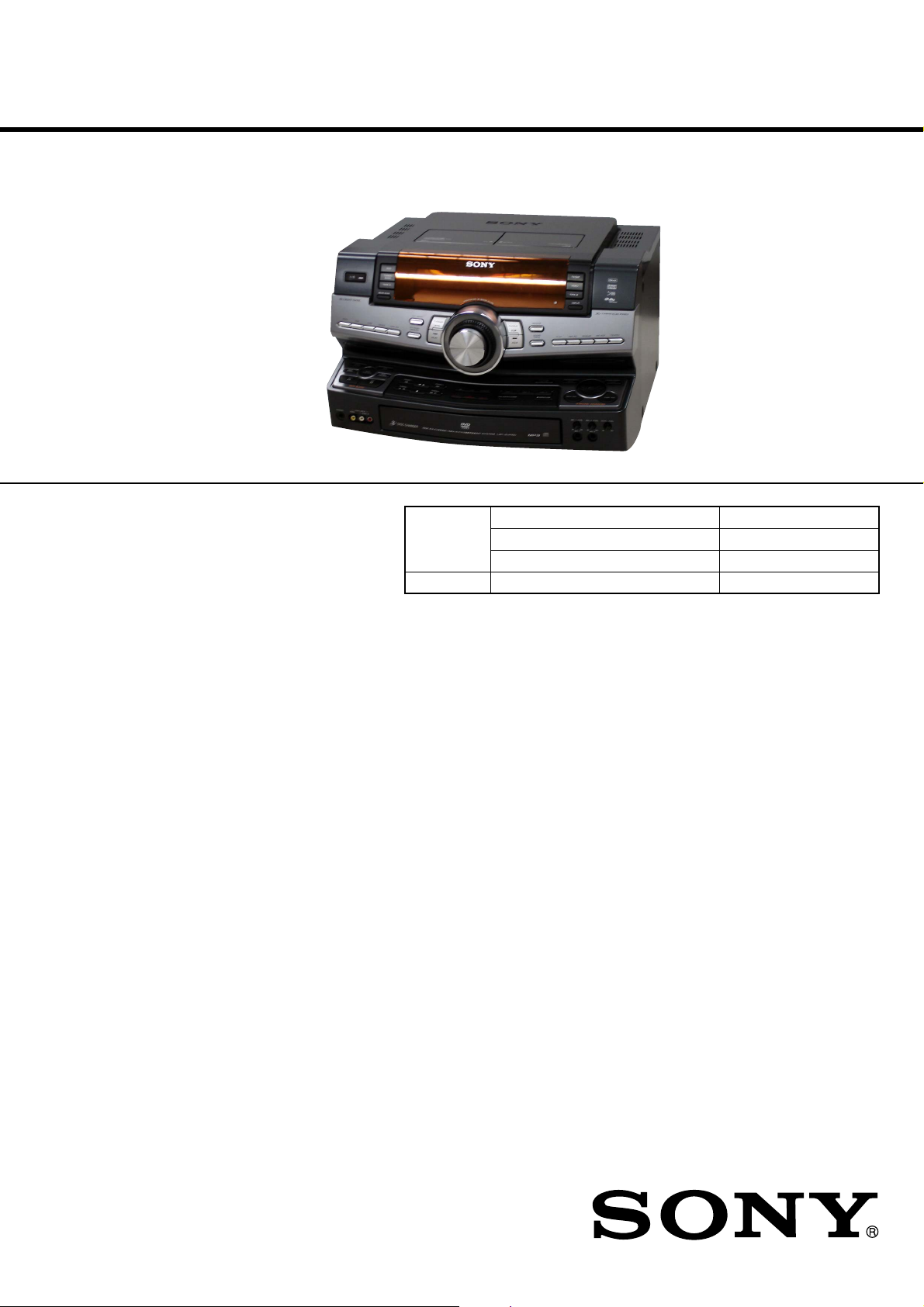
HCD-ZUX10D
SERVICE MANUAL
Ver. 1.2 2007.10
• HCD-ZUX10D is the tuner, deck, DVD
and amplifier section in LBT-ZUX10D.
Model Name Using Similar Mechanism HCD-GNZ777D/GNZ888D
DVD Section CD Mechanism Type CDM74HF-DVBU101
Optical Pick-up Name KHM-313CAB/C2NP
Tape Section Model Name Using Similar Mechanism HCD-GN1100D
SPECIFICATIONS
E Model
Australian Model
Amplifier section
The following are measured at AC 120, 127,
220, 240V 50/60 Hz
Power Output (rated):
170 W + 170 W (6 Ω, 1 kHz, 1% THD)
RMS output power (reference)
Front speaker:
260 W + 260 W (per channel at 6 Ω,
1 kHz, 10% THD)
Center speaker:
80 W (per channel at 6 Ω, 1 kHz,
10% THD)
Surround speaker:
260 W + 260 W (per channel at 6 Ω,
1 kHz, 10% THD)
Inputs
VIDEO INPUT:
VIDEO: 1 Vp-p, 75 ohms
AUDIO L/R: Voltage 250 mV,
impedance 47 kilohms
TV/SAT AUDIO IN L/R:
Voltage 250 mV/450 mV, impedance
47 kilohms
MIC 1 or 2:
Sensitivity 1 mV, impedance
10 kilohms
Outputs
AUDIO OUT:
Voltage 250 mV, impedance 1 kilohm
VIDEO OUT:
Max. output level 1 Vp-p, unbalanced,
Sync. negative load impedance
75 ohms
COMPONENT VIDEO OUT:
Y: 1 Vp-p, 75 ohms
PB/CB: 0.7 Vp-p, 75 ohms
PR/CR: 0.7 Vp-p, 75 ohms
S VIDEO OUT:
Y: 1 Vp-p, unbalanced, Sync. negative
C: 0.286 Vp-p, load impedance
75 ohms
PHONES:
accepts headphones of 8 ohms or more
SUBWOOFER OUT:
Voltage 1 V, impedance 1 kilohm
– Continued on next page –
9-887-800-03
2007J04-1
© 2007.10
DVD DECK RECEIVER
Sony Corporation
Personal Audio Division
Published by Sony Techno Create Corporation

HCD-ZUX10D
Disc player section
System
Compact disc and digital audio and
video system
Laser
Semiconductor laser (DVD: λ =
650 nm, CD: λ = 790 nm)
Emission duration: continuous
Frequency response
DVD (PCM 48 kHz): 2 Hz – 22 kHz
(±1 dB)
CD: 2 Hz – 20 kHz (±0.5 dB)
Video color system format
Latin American models: NTSC
Other models: NTSC and PAL
Tape deck section
Recording system
4-track 2-channel stereo
Frequency response
50 – 13,000 Hz (±3 dB),
using Sony TYPE I tape
Tuner section
FM stereo, FM/AM superheterodyne tuner
FM tuner section
Tuning range
87.5 – 108.0 MHz (50 kHz step)
Antenna
FM lead antenna
Antenna terminals
75 ohms unbalanced
Intermediate frequency
10.7 MHz
General
Power requirements
Oceanian models: 230 – 240 V AC,
50/60 Hz
Other models: 120 V, 220 V or
230 – 240 V AC, 50/60 Hz, adjustable
with voltage selector
Power consumption
420 W
Dimensions (Approx.)
491 × 297.5 × 460 mm (w/h/d)
Mass (Approx.)
20 kg
Supplied accessories:
Remote Commander (2)
R6 (size AA) batteries (4)
AM loop antenna (1)
FM lead antenna (1)
Video cord (1)
Front speaker pads (8)
Surround speaker pads (8)
Center speaker pads (4)
Speaker cords (5)
Design and specifications are subject to
change without notice.
AM tuner section
Tuning range
Latin American and Oceanian models:
530 – 1,710 kHz (with the interval set
at 10 kHz)
531 – 1,710 kHz (with the interval set
at 9 kHz)
Other models:
531 – 1,602 kHz (with the interval set
at 9 kHz)
530 – 1,610 kHz (with the interval set
at 10 kHz)
Antenna
AM loop antenna
Antenna terminals
External antenna terminal
Intermediate frequency
450 kHz
SAFETY-RELATED COMPONENT WARNING!!
COMPONENTS IDENTIFIED BY MARK 0 OR DOTTED LINE
WITH MARK 0 ON THE SCHEMATIC DIAGRAMS AND IN
THE PARTS LIST ARE CRITICAL TO SAFE OPERATION.
REPLACE THESE COMPONENTS WITH SONY PARTS WHOSE
PA RT NUMBERS APPEAR AS SHOWN IN THIS MANUAL OR
IN SUPPLEMENTS PUBLISHED BY SONY.
2
HCD-ZUX10D
Ver. 1.2
Notes on chip component replacement
• Never reuse a disconnected chip component.
• Notice that the minus side of a tantalum capacitor may be
damaged by heat.
Flexible Circuit Board Repairing
• Keep the temperature of the soldering iron around 270 ˚C
during repairing.
• Do not touch the soldering iron on the same conductor of the
circuit board (within 3 times).
• Be careful not to apply force on the conductor when soldering
or unsoldering.
UNLEADED SOLDER
Boards requiring use of unleaded solder are printed with the leadfree mark (LF) indicating the solder contains no lead.
(Caution: Some printed circuit boards may not come printed with
the lead free mark due to their particular size)
: LEAD FREE MARK
Unleaded solder has the following characteristics.
• Unleaded solder melts at a temperature about 40 ˚C higher
than ordinary solder.
Ordinary soldering irons can be used but the iron tip has to be
applied to the solder joint for a slightly longer time.
Soldering irons using a temperature regulator should be set to
about 350 ˚C.
Caution: The printed pattern (copper foil) may peel away if
the heated tip is applied for too long, so be careful!
• Strong viscosity
Unleaded solder is more viscous (sticky, less prone to flow)
than ordinary solder so use caution not to let solder bridges
occur such as on IC pins, etc.
• Usable with ordinary solder
It is best to use only unleaded solder but unleaded solder may
also be added to ordinary solder.
NOTES ON LASER DIODE EMISSION CHECK
The laser beam on this model is concentrated so as to be focused on
the disc reflective surface by the objective lens in the optical pickup block. Therefore, when checking the laser diode emission,
observe from more than 30 cm away from the objective lens.
Laser component in this product is capable
of emitting radiation exceeding the limit for
Class 1.
This appliance is
claassified as a CLASS 1
LASER product. This
label is located on the
rear exterior.
CAUTION
Use of controls or adjustments or performance of procedures
other than those specified herein may result in hazardous radiation
exposure.
NOTES ON HANDLING THE OPTICAL PICK-UP
BLOCK OR BASE UNIT
The laser diode in the optical pick-up block may suffer electrostatic
break-down because of the potential difference generated by the
charged electrostatic load, etc. on clothing and the human body.
During repair, pay attention to electrostatic break-down and also
use the procedure in the printed matter which is included in the
repair parts.
The flexible board is easily damaged and should be handled with
care.
3
HCD-ZUX10D
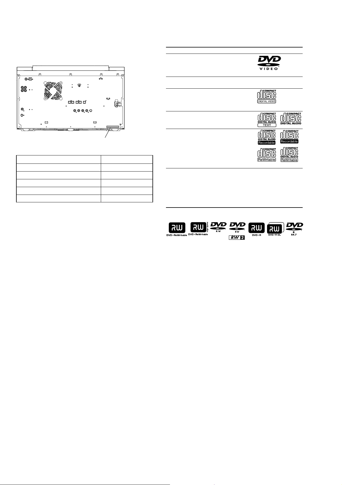
MODEL IDENTIFICATION
– BACK PANEL –
PA RT No.
Model Part No.
E3 3-100-831-0s
MY, SP 3-100-831-1s
AUS 3-100-831-2s
E2 3-100-831-3s
E51 3-100-831-4s
PLAYABLE DISCS
Type Characteristics Logo
DVD VIDEO • DVD VIDEO
VR mode • DVD-R/-RW in VR (Video
VIDEO CD • VIDEO CD
CD • AUDIO CD
DATA CD • CD-ROM/-R/-RW in DATA
DATA DVD • DVD-ROM/-R/-RW/+R/+RW
•DVD-R*/-RW*/+R/+RW in
DVD VIDEO format
* also in video mode
Recording) mode
• Super VCD
• CD-R/-RW in VIDEO CD or
Super VCD format
• CD-R/-RW in AUDIO CD
format
CD format, containing MP3
audio tracks1), JPEG image
files2) or DivX video files3),
and conforming to ISO 9660
Level 1 or Level 2, or Joliet
(expansion format).
in DATA DVD format,
containing MP3 audio tracks1),
JPEG image files2) or DivX
video files3), and conforming
to UDF (Universal Disk
Format).
4)
•Abbreviation
E2 : 120 V AC area in E model
E3 : 240 V AC area in E model
E51 : Chilean and Peruvian model
AUS: Australian model
MY : Malaysia model
SP : Singapore model
This system can also play back discs with the following disc logos:
1)
MP3 (MPEG 1 Audio Layer 3) is a standard format defined by ISO/
MPEG which compresses audio data. MP3 audio tracks must be in MPEG
1 Audio Layer 3 format.
2)
JPEG image files must conform to the DCF image file format. (DCF
“Design rule for Camera File System”: Image standards for digital cameras
regulated by Japan Electronics and Information Technology Industries
Association (JEITA)).
3)
DivX video files must be recorded in DivX format with the extension
“.AVI” or “.DIVX”.
4)
A logical format of files and folders on CD-ROMs, defined by ISO
(International Organization for Standardization).
DivX® is a video file compression technology, developed by DivX, Inc..
DivX, DivX Certified, and associated logos are trademarks of DivX, Inc.
and are used under license.
“DVD+RW”, “DVD-RW”, “DVD+R”, “DVD VIDEO”, and the “CD” logos
are trademarks.
4

TABLE OF CONTENTS
HCD-ZUX10D
1. SERVICING NOTES
Loading Panel .................................................................. 6
2. GENERAL
Guide to Parts and Controls............................................. 7
3. DISASSEMBLY
3-1. Side R Panel, Side L Panel .............................................. 16
3-2. Top Case Section ............................................................. 16
3-3. Back Panel Section .......................................................... 17
3-4. Loading Panel .................................................................. 17
3-5. Front Panel Section ......................................................... 18
3-6. Tape Mechanism Deck .................................................... 18
3-7. Holder (TC-L), Holder (TC-R) ....................................... 19
3-8. Power AMP Section ........................................................ 19
3-9. Main Board ...................................................................... 20
3-10. FL Board, Power LED Board .......................................... 20
3-11. Illumination Board, VOL Board ...................................... 21
3-12. MIC Board, VR Board, Base R LED Board ................... 21
3-13. HP-Video Board, Base L LED Board ............................. 22
3-14. Center Key Board, Beat Creator Board,
X-Round Board ............................................................... 22
3-15. Bracket (Trans) ................................................................ 23
3-16. DMB16 Board, Video Board ........................................... 23
3-17. DVD Mechanism Deck ................................................... 24
3-18. Driver Board, SW Board ................................................. 24
3-19. Optical Pick-Up ............................................................... 25
3-20. Sensor Board ................................................................... 25
3-21. Motor (TB) Board ........................................................... 26
3-22. Motor (LD) Board ........................................................... 26
4. TEST MODE .............................................................. 27
5. MECHANICAL ADJUSTMENTS ....................... 32
6. ELECTRICAL ADJUSTMENTS ......................... 32
7. DIAGRAMS
7-1. Block Diagram – RF/Servo Section – ............................. 35
7-2. Block Diagram – Video Section – ................................... 36
7-3. Block Diagram – Tape/Tuner Section – .......................... 37
7-4. Block Diagram – Main Section – .................................... 38
7-5. Block Diagram – Effector Section – ............................... 39
7-6. Block Diagram – AMP Section – .................................... 40
7-7. Block Diagram – Display/Power Section – ..................... 41
7-8. Printed Wiring Boards – Driver Section –....................... 45
7-9. Schematic Diagram – Driver Section – ........................... 46
7-10. Printed Wiring Board – Main Section – .......................... 47
7-11. Schematic Diagram – Main Section (1/4) – .................... 48
7-12. Schematic Diagram – Main Section (2/4) – .................... 49
7-13. Schematic Diagram – Main Section (3/4) – .................... 50
7-14. Schematic Diagram – Main Section (4/4) – .................... 51
7-15. Printed Wiring Board – DMB16 Section (1/2) – ............. 52
7-16. Printed Wiring Board – DMB16 Section (2/2) – ............. 53
7-17. Schematic Diagram – DMB16 Section (1/6) – ............... 54
7-18. Schematic Diagram – DMB16 Section (2/6) – ............... 55
7-19. Schematic Diagram – DMB16 Section (3/6) – ............... 56
7-20. Schematic Diagram – DMB16 Section (4/6) – ............... 57
7-21. Schematic Diagram – DMB16 Section (5/6) – ............... 58
7-22. Schematic Diagram – DMB16 Section (6/6) – ............... 59
7-23. Printed Wiring Boards – HP-Video/MIC Section – ........ 60
7-24. Schematic Diagram – HP-Video/MIC Section –............. 61
7-25. Printed Wiring Board – Karaoke Section – ..................... 62
7-26. Schematic Diagram – Karaoke Section – ........................ 63
7-27. Printed Wiring Board – Video Section – ......................... 64
7-28. Schematic Diagram – Video Section – ............................ 65
7-29. Printed Wiring Board – VR Section – ............................. 66
7-30. Schematic Diagram – VR Section – ................................ 67
7-31. Printed Wiring Board – Center AMP Section – .............. 68
7-32. Schematic Diagram – Center AMP Section – ................. 69
7-33. Printed Wiring Board – Effector Section – ...................... 70
7-34. Schematic Diagram – Effector Section – ........................ 71
7-35. Printed Wiring Board – Power AMP Section – ............... 72
7-36. Schematic Diagram – Power AMP Section – .................. 73
7-37. Printed Wiring Board – FL Section – .............................. 74
7-38. Schematic Diagram – FL Section – ................................. 75
7-39. Printed Wiring Boards – Key Section (1/2) – .................. 76
7-40. Printed Wiring Boards – Key Section (2/2) – .................. 77
7-41. Schematic Diagram – Key Section – ............................... 78
7-42. Printed Wiring Boards – LED Section (1/2) – ................ 79
7-43. Printed Wiring Boards – LED Section (2/2) – ................ 80
7-44. Schematic Diagram – LED Section –.............................. 81
7-45. Printed Wiring Boards – Power Section – ....................... 82
7-46. Schematic Diagram – Power Section – ........................... 83
8. EXPLODED VIEWS
8-1. Main Section ................................................................... 100
8-2. Front Panel Section (1) ................................................... 101
8-3. Front Panel Section (2) ................................................... 102
8-4. Front Panel Section (3) ................................................... 103
8-5. Top Case Section ............................................................ 104
8-6. Back Panel Section ......................................................... 105
8-7. Chassis Section ............................................................... 106
8-8. DVD Mechanism Section (1) ......................................... 107
8-9. DVD Mechanism Section (2) ......................................... 108
9. ELECTRICAL PARTS LIST............................... 109
5
HCD-ZUX10D
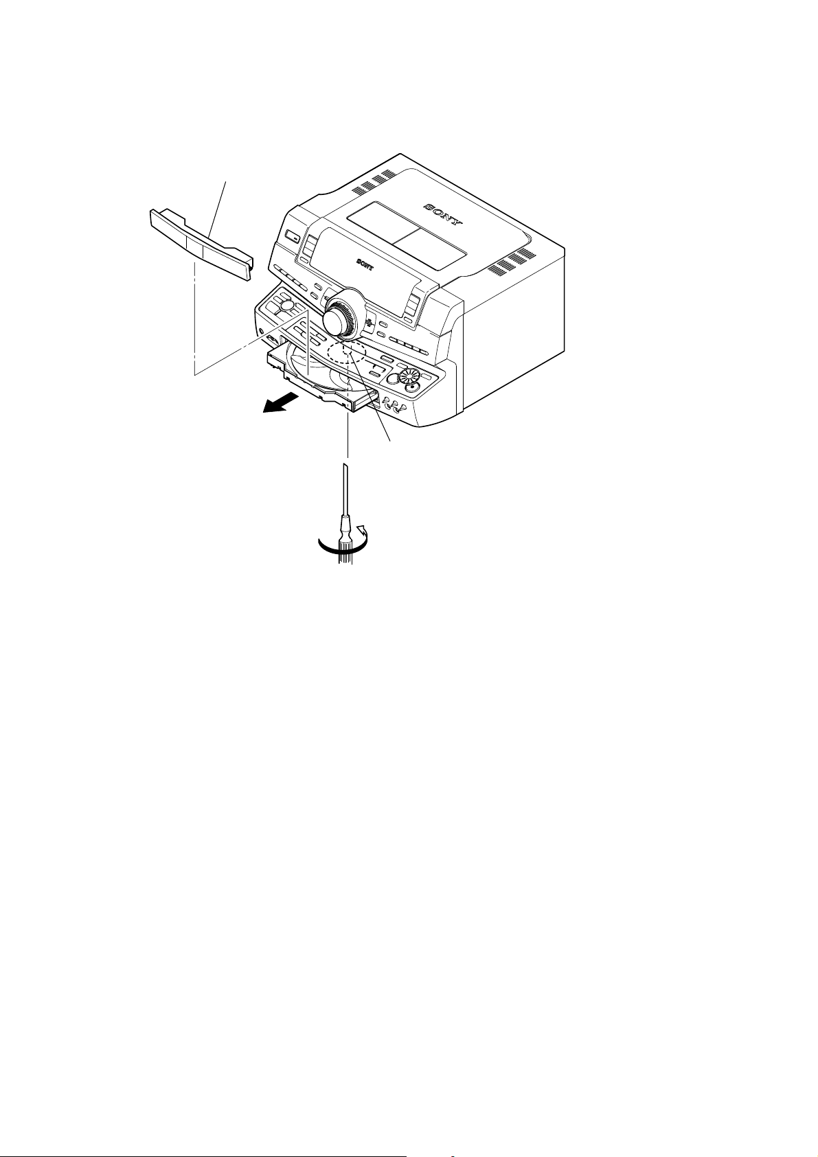
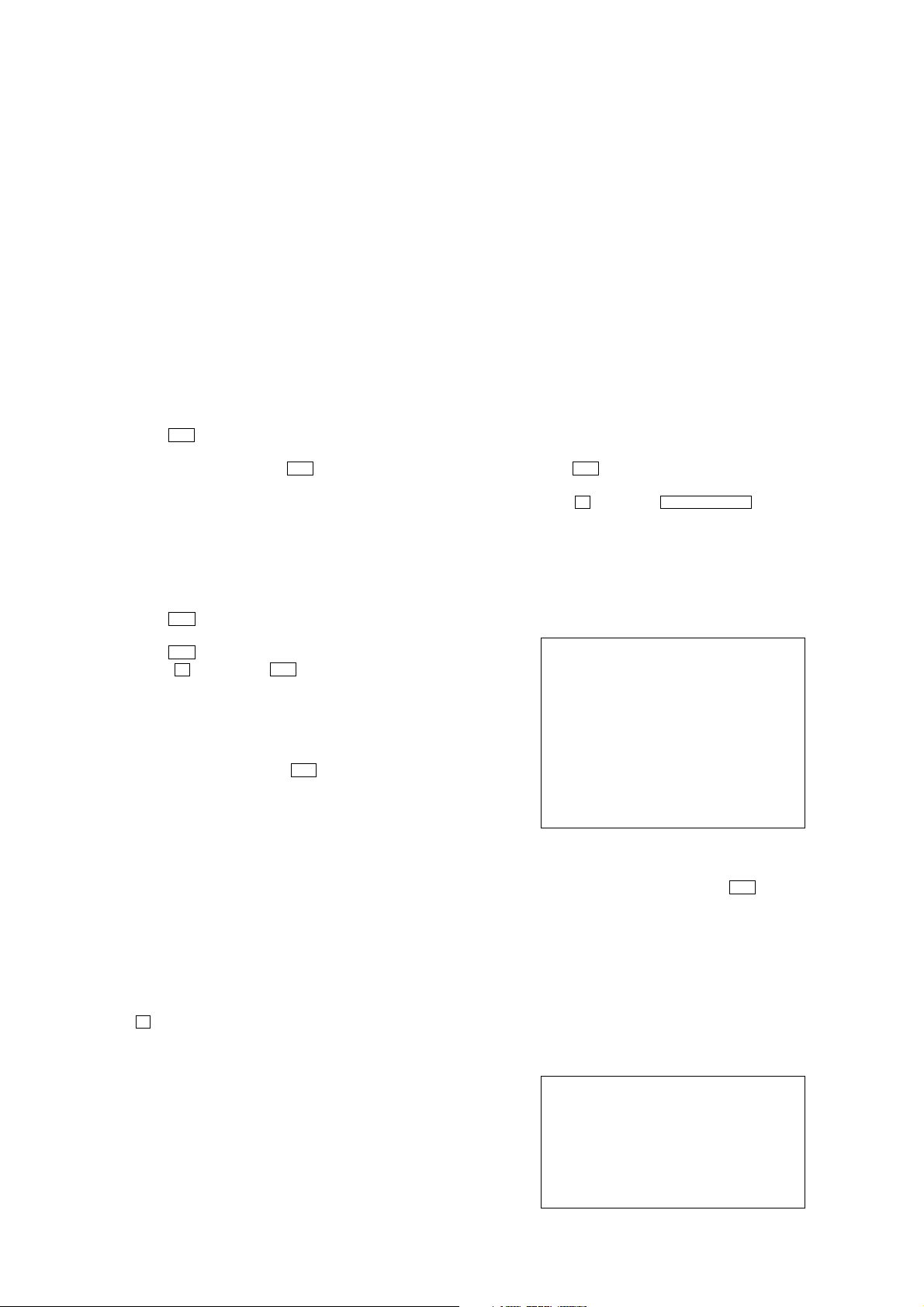
LOADING PANEL
3
loading panel
2
SECTION 1
SERVICING NOTES
gear (shaft)
1
Turn the gear (shaft) in the direction of the arrow.
6
SECTION 2
8
GENERAL
HCD-ZUX10D
This section is extracted from
instruction manual.
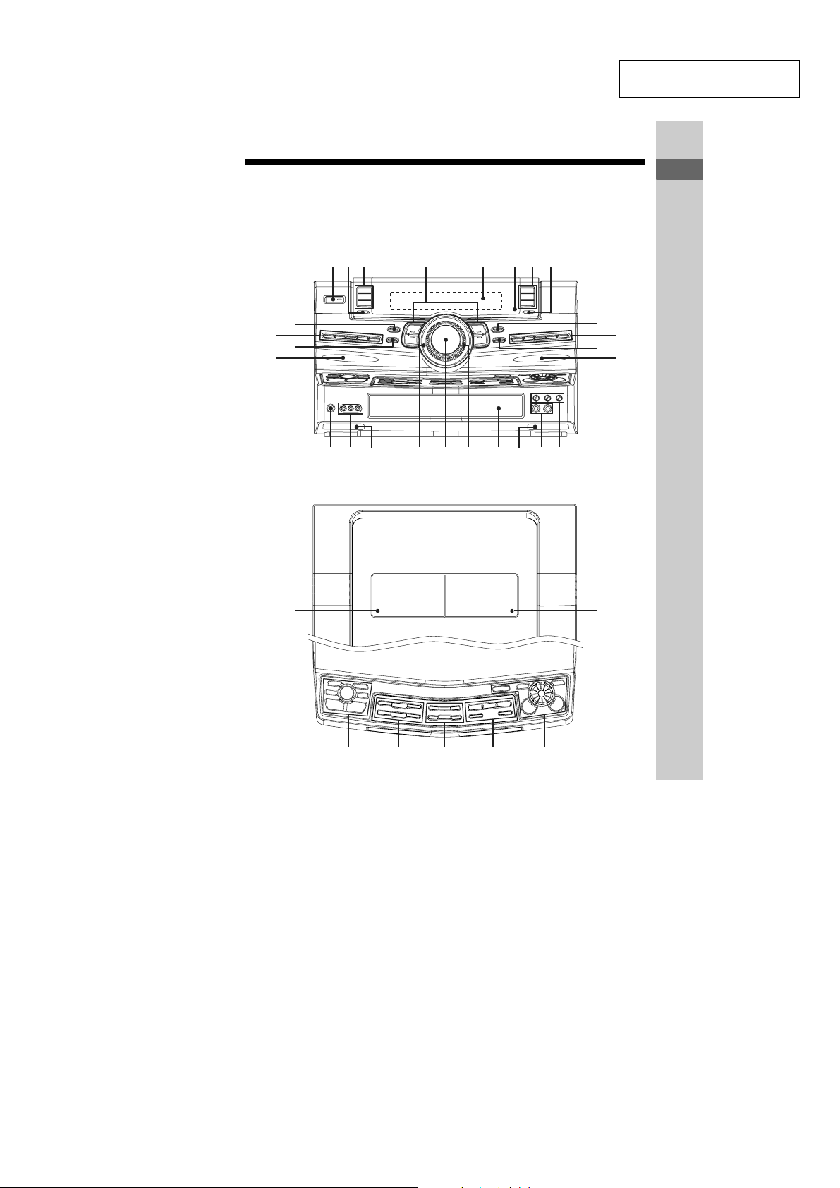
Guide to parts and controls
This manual mainly explains operations using the remote, but the same operations can
also be performed using the buttons on the unit having the same or similar names.
Front view
123 6547
wg
wd
Top view
wh
wf
ws wa w; ql qk qj qh qg qf
qd
9
qa
q;
qs
Guide to parts and controls
wj
ed es ea
e;
wl
wk
Continued
l
GB
9
7

HCD-ZUX10D
1 "/1 (on/standby) (pages 18, 19,
20, 54, 77, 78, 84)
Press to turn the system on or off.
B BEAM MODE (page 71)
Press to change the lighting effect of
a beam.
C DVD (pages 19, 27, 56, 65, 71,
82)
TUNER/BAND (pages 53, 71)
TAPE A (pages 55, 71)
Press to select a function.
D FLANGER (pages 60, 79, 84)
DELAY (pages 60, 79, 84)
CHORUS (pages 61, 79, 84)
AQUA (pages 61, 79, 84)
Press to select an effector mode.
E Display (pages 13, 72, 85)
F IR Receptor (page 79)
G TV/SAT (pages 71, 76, 79)
VIDEO (pages 71, 77)
TAPE B (pages 55, 69, 71)
Press to select a function.
H DISPLAY (pages 71, 72)
Press to change the information in
the front panel display.
I GROOVE (page 58)
Press to reinforce the bass.
J FLAT (page 58)
MP3 EQ (pa
REGGAE (page 58)
HIP HOP (page 58)
TECHNO (page 58)
Press to select a preset effect.
K SOUND FIELD (page 59)
ess to select a sound field.
Pr
L FRONT BEAM (right) (pages 71,
79)
GB
10
ge 58)
M MIC 1/2 LEVEL (pages 57, 65,
78)
Turn to adjust the microphone
volume.
ECHO LEVEL (page 65)
Turn to adjust the microphone echo
effect.
N MIC 1/2 (jack) (pages 57, 65, 78)
Connect the microphones.
O BOTTOM BEAM (right) (page 71)
P Disc tray (pages 13, 27, 80)
Q OPERATION DIAL (pages 58,
63, 70)
Turn to select a setting.
R MASTER VOLUME (pages 27,
69, 78)
Turn to adjust the volume.
S Power illuminator (page 70)
T BOTTOM BEAM (left) (page 71)
U VIDEO INPUT (jacks) (page 75)
Connect an audio or video
component.
V PHONES (jack) (page 78)
Connect the headphones.
W FRONT BEAM (left) (pages 71,
79)
X EQ BAND/MEMORY (page 58)
Press to select a frequency band
when adjusting the graphic
equalizer.
Y ROCK (page 58)
POP (page 58)
JAZZ (page 58)
DANCE (page 58)
Press to select a preset effect.
USER EQ (page 58)
Press to select a user equalizer.
8

HCD-ZUX10D
Z AMP MENU (page 70)
Press to change the spectrum
analyser display, adjust the
brightness of the display and built-in
beam or change the power
illuminator pattern.
wj A Z PUSH OPEN/CLOSE
(Eject A) (page 55)
Press to insert or eject a tape.
Deck A (page 55)
wk B PUSH Z OPEN/CLOSE
(Eject B) (page 55)
Press to insert or eject a tape.
Deck B (pages 55, 56, 69)
wl X-ROUND ON/OFF (pages 61,
62)
Press to turn on or off the X-ROUND
mode.
X-ROUND MODE (pages 61, 62)
Press to select an X-ROUND mode.
MAX/JUMP MODE (page 62)
Press to select the way of creating the
“MAX” and “JUMP” effect.
X-ROUND JOG (page 62)
Turn to change the sound movement
or the speed of the sound movement.
MAX PAD (page 62)
Press to enhance the sound.
JUMP PAD (page 62)
Press to switch the sound position to
the opposite direction.
e; DISC 1 ~ 3 (page 28)
Press to select a disc or switch to
DVD function from another source.
DISC SKIP/EX-CHANGE
(pages 19, 27, 28)
Press to exchange other discs during
playback.
Z OPEN/CLOSE (pages 19, 27,
80)
Press to load or eject a disc.
ea X (pause) (pages 27, 55)
Press to pause playback.
ENTER (pages 23, 31, 53, 58,
69, 84)
Press to enter the selection.
PROGRESSIVE (pages 21, 76,
82)
Press to select the format of the video
signals output from the
COMPONENT VIDEO OUT jacks.
CD SYNC (page 56)
Press to start CD Synchro Recording.
REC PAUSE/START (page 56)
Press to start manual recording.
DIRECTION (pages 55, 69)
Press to select the tape playback and
recording option.
Guide to parts and controls
Continued
l
11
GB
9

HCD-ZUX10D
es PRESET –/+ (page 53)
Press to select a preset station.
./> (go backward/go
forward) (pages 27, 38, 56, 84)
Press to select a track, chapter or
DivX video file.
TUNING –/+ (pages 53, 54)
Press to tune in a radio station.
m/M (rewind/fast
forward) (page 27)
Press to rewind or fast forward.
Press to watch frame by frame when
playback is paused.
nN (play) (pages 27, 55, 78)
Press to start playback.
x (stop) (pages 27, 53, 55)
Press to stop playback or recording.
ed BEAT ON/OFF (page 63)
Press to turn on
the beat.
BEAT LEVEL (page 63)
Press to adjust the beat level.
BEAT SPEED (page 64)
Press to change the beat speed.
BEAT PATTERN (page 64)
Press to select the rhythms of the
beat.
BPM CONTROL (page 64)
Press to input the tempo of the audio
source.
PAD A/PAD B (page 63)
Press to add percussion sound.
or off the rhythms of
10
12
GB
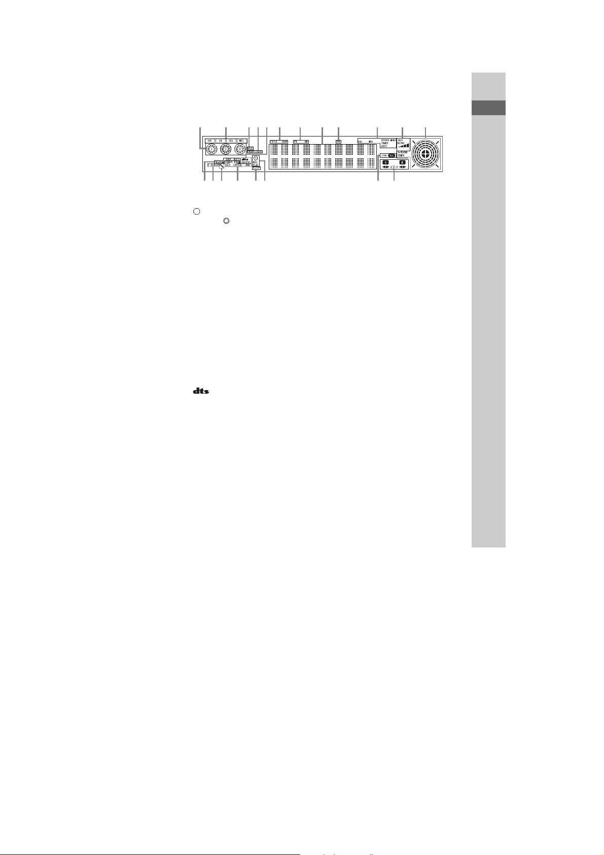
Display
q
q
1
w;
HCD-ZUX10D
Guide to parts and controls
qj
3
qh
546
g
789
q;
qa
qs
RELAY
qd
f
2
qkql
A Indicators for the disc tray (page 27).
“” lights up when the disc is
selected. “ ” lights up when there is
a disc on the disc tray. “1”, “2” and
“3” light up when the system is turned
on.
B Indicators for the DVD function
(page 27).
“DVD” lights up when DVD VIDEO,
DVD-R/-RW in VR mode or DATA
DVD is detected. “CD” lights up
when AUDIO CD or DAT A CD is
detected. “VCD” lights up when
VIDEO CD or Super VCD is
detected. “MP3” lights up when MP3
audio tracks are played back.
C Lights up when the color system of
the video output is NTSC (page 20).
D Lights up when “P AUTO” or
“P VIDEO” is selected (page 21).
E “” lights up when DTS source is
played back (page 50).
“; DIGITAL” lights up when Dolby
Digital source is played back
(page 50).
F Lights up when the elapsed playing
time and the remaining playing time
for the title or chapter is displayed
(page 72).
G Indicators for the tuner band
(page 53).
H Displays the current status and
information (page 72).
I Lights up when VIDEO CD with PBC
functions is played back (page 30).
J Indicators for the TUNER function
(page 53).
K Indicators for the BEAT BLEND
mode (page 63).
L Indicators for the X-ROUND mode
(page 61).
M Indicators for the TAPE function
(page 55).
“A” and “B” lights up when the
system is turned on.
“b” or “B” lights up when there is a
tape in the deck and indicates the tape
playback direction. “RELAY ”, “g”
and “j” indicates the tape
playback option.
N Indicators for the recording type and
status (page 56).
O Lights up when the Play Timer or
Recording Timer is set (page 69).
P Lights up when the Sleep Timer is
activated (page 69).
Q Indicators for sound field (page 59).
“; PL” or “; PL II” li gh ts up whe n
Pro Logic decoding or Pro Logic II
Movie/Music decoding is performed.
“VIRTUAL” lights up when “HP
VIRTUAL” is selected. “VIRTUAL”
and “DCS” light up when
“V.M .DIM.” is selected. “LINK”
lights up when “LINK” is selected.
R Lights up when Karaoke Mode is
turned on (page 65).
S “GROOV E” lights up when
“GROOV E ON” is selected.
“Z GROOVE” lights up when
“Z-GROOVE ON” is selected
(page 58).
Continued
l
13
GB
11
HCD-ZUX10D
T Indicates the selected play mode
(page 31).
“SHUF” lights up when Shuffle Play
is activated. “PROGRAM” lights up
when Program Play is activated.
“REP” lights up when Repeat Play is
set to “ALL DISCS”, “ONE DISC”,
“A LBUM” or “ON”. “REP 1” lights
up when Repeat Play is set to
“TITLE”, “CHAPTER”, “TRACK”
or “FILE”.
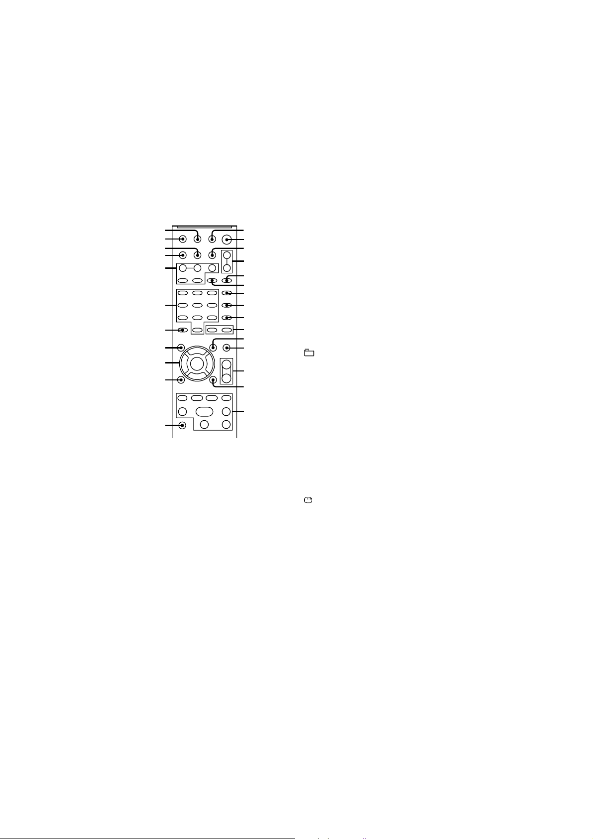
Remote (RM-AMU005)
wh
wg
wf
wd
ws
wa
w;
ql
qk
qj
qh
1 THEATRE SYNC (page 26)
Press to operate the THEATR E
SYNC function.
B TV "/1 (on/standby) (page 22)
Press to turn the TV on or off.
"/1 (on/standby) (pages 18, 23,
78)
Press to turn the system on or off.
GB
14
1
2
3
4
5
6
7
8
9
q;
qa
qs
qd
qf
qg
C DISC SKIP (page 28)
Press to select the next disc.
D FUNCTION +/– (pages 27, 53,
55, 76)
Press to select a function.
E PICTURE NAVI (pages 36, 38)
Press to search for a scene or a JPEG
image file.
F REPEAT/FM MODE (pages 34,
54, 83)
Press to change the Repeat Play
setting.
Press to select the FM monaural or
stereo reception.
G AUDIO (pages 29, 65, 74)
Press to select the audio format.
H SUBTITLE/D.TUNING
(pages 29, 54)
Press to turn on or off or change the
language of the subtitle.
Press to enter direct tuning mode.
I ANGLE (page 28)
Press to change the angle.
J +/– (pages 25, 27)
Press to select an album.
K DVD/TUNER MENU (pages 34,
38, 53)
Press to display the menu of the
DVD VIDEO.
Press to preset a radio station.
L SOUND FIELD (page 59)
Press to select a sound field.
M TV VOL +/–* (page 22)
Press to adjust the TV volume.
VOLUME +/–* (pages 27, 69, 78)
Press to adjust the volume.
N DISPLAY (pages 31, 47, 66,
90)
Press to turn on or off or change the
Control Menu display on the TV
screen.
12

HCD-ZUX10D
O TV CH +/– (page 22)
Press to select a TV channel.
PRESET +/– (page 53)
Press to select a preset station.
./> (go backward/go
forward) (pages 27, 38, 56, 84)
Press to select a track, chapter or
DivX video file and to adjust the time
when setting the clock or timer.
c STEP C (page 28)
Press to watch one frame at a time.
REPLAY /ADVANCE
(page 28)
Press to replay the previous scene or
briefly fast forward the current
scene.
TUNING +/– (pages 53, 54)
Press to tune in a radio station.
SLOW /SLOW (page 28)
Press to watch frame by frame.
m/M (rewind/fast forward
(page 27)
Press to rewind or fast forward.
H* (play) (pages 27, 55, 78)
X (pause) (pages 27, 55)
x (stop) (pages 27, 53, 55)
Press to start, pause or stop playback.
P TV (page 22)
Hold down TV and press the button
you want to operate the TV.
Q O RETURN (pages 30, 37, 38)
Press to return to the previous
display.
R V/v/B/b (pages 23, 31, 53, 66,
69)
Press to select the settings.
ENTER (pages 23, 31, 53, 58,
69)
Press to enter the selection.
S DVD TOP MENU (page 34)
Press to display the DVD title.
T -/-- (page 22)
Press to enter a double digit channel
number for TV.
CLEAR (pages 24, 25, 32, 39)
Press to cancel the play mode or clear
a mistake when you press the
incorrect numeric button.
U Numeric buttons* (pages 22, 27,
44, 53)
Press to tune or preset a radio station,
enter a track or file number, etc.
V KEY CONTROL 2/# (page 67)
SCORE (page 67)
KARAOKE MODE (page 65)
KARAOKE PON (page 67)
Press to enjoy the karaoke function.
W DISPLAY (pages 71, 72)
Press to change the information in
the front panel display.
wf TIME/TEXT (pages 72, 73)
Press to check the elapsed playing
time, remaining time, title, etc.
wg TV INPUT (page 22)
Press to switch the TV’s input
source.
SLEEP (pages 25, 69)
Press to activate the Sleep Timer.
wh TIMER MENU (pages 23, 69)
Press to set the clock and timer.
Guide to parts and controls
Continued
l
15
GB
13
HCD-ZUX10D
* The numeric button 5, TV VOL +, VOLUME
+ and H buttons have a tactile dot. Use the
tactile dot as a reference when operating the
system.
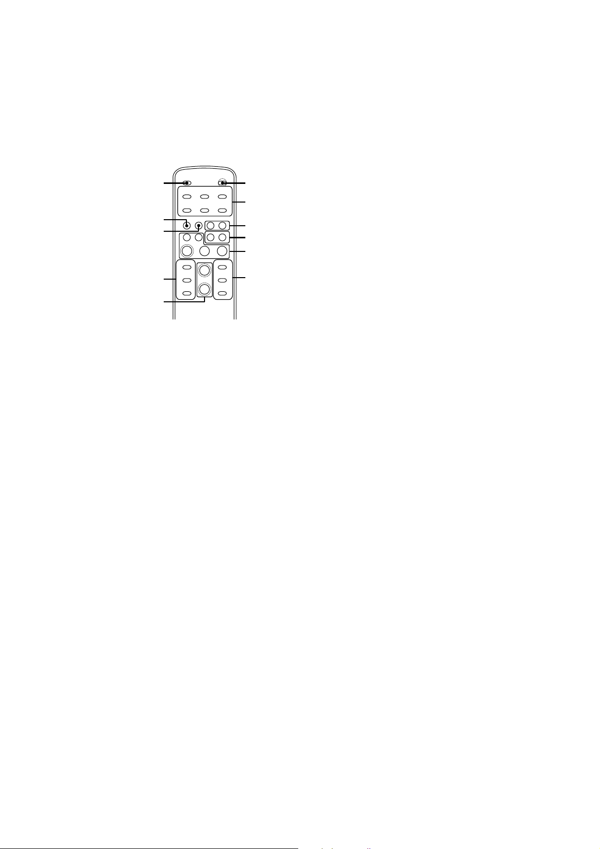
X-TRANCE PRO remote
(RM-AMU007)
qa
q;
9
8
7
1 "/1 (on/standby) (pages 18, 23,
78)
Press to turn the system on or off.
B X-ROUND ON/OFF (pages 61,
62)
Press to turn on or off the X-ROUND
mode.
1
2
3
4
5
6
3 PA D A (page 63)
PA D B (page 63)
Press to add percussion sound.
4 FRONT BUILT-I N BEAM
(page 71)
BOTTOM BUILT-IN BEAM
(page 71)
Press to change the lighting effect of
the beam.
E –./>+ (go backward/go
forward) (pages 27, 38, 56, 84)
Press to select a track or file.
N (play) (pages 27, 55, 78)
X (pause) (pages 27, 55)
x (stop) (pages 27, 53, 55)
Press to start, pause or stop playback.
F BEAT LEVEL (page 63)
Press to adjust the beat level.
BEAT PATTERN +/– (page 64)
Press to select the rhythms of the
beat.
G VOLUME +/–* (pages 27, 69, 78)
Press to adjust the volume.
8 BEAT ON/OFF (page 63)
Press to turn on or off the rhythms of
the beat.
16
X-ROUND MODE (pages 61, 62)
Press to select an X-ROUND mode.
MAX PAD (page 62)
Press to enhance the sound.
BEAT SPEED +/– (page 64)
Press to change the beat speed.
I GROOVE (page 58)
Press to reinforce the bass.
J SOUND EFFECT (page 61)
JUMP PAD (page 62)
Press to switch the sound position to
the opposite direction.
X-ROUND +/– (page 62)
Press to change the sound movement
or the speed of the sound movement.
GB
Press to select an effector mode.
K FUNCTION (pages 27, 53, 55,
76)
Press to select a function.
* The VOLUME + button has a tactile dot. Use
the tactile dot as a reference when operating
the system.
14
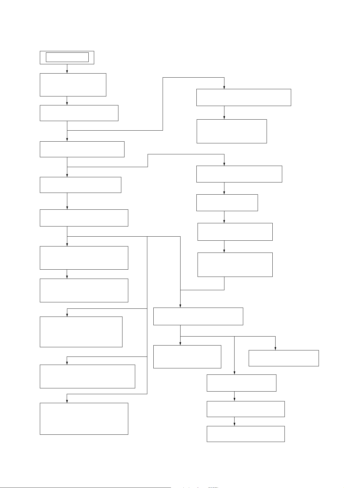
Note: Disassemble the unit in the order as shown below.
SET
3-1. SIDE R PANEL,
SIDE L PANEL
(Page 16)
3-2. TOP CASE SECTION
(Page 16)
3-3. BACK PANEL SECTION
(Page 17)
3-4. LOADING PANEL
(Page 17)
HCD-ZUX10D
SECTION 3
DISASSEMBLY
3-6. TAPE MECHANISM DECK
(Page 18)
3-7. HOLDER (TC-L),
HOLDER (TC-R)
(Page 19)
3-8. POWER AMP SECTION
(Page 19)
3-5. FRONT PANEL SECTION
(Page 18)
3-10. FL BOARD,
POWER LED BOARD
(Page 20)
3-11. ILLUMINATION BOARD,
VOL BOARD
(Page 21)
3-12. MIC BOARD,
VR BOARD,
BASE R LED BOARD
(Page 21)
3-13. HP-VIDEO BOARD,
BASE L LED BOARD
(Page 22)
3-9. MAIN BOARD
(Page 20)
3-15. BRACKET (TRANS)
(Page 23)
3-16. DMB16 BOARD,
VIDEO BOARD
(Page 23)
3-17. DVD MECHANISM DECK
(Page 24)
3-18. DRIVER BOARD,
SW BOARD
(Page 24)
3-20. SENSOR BOARD
(Page 25)
3-19. OPTICAL PICK-UP
(Page 25)
3-14. CENTER KEY BOARD,
BEAT CREATOR BOARD,
X-ROUND BOARD
(Page 22)
3-21. MOTOR (TB) BOARD
(Page 26)
3-22. MOTOR (LD) BOARD
(Page 26)
15
HCD-ZUX10D
)
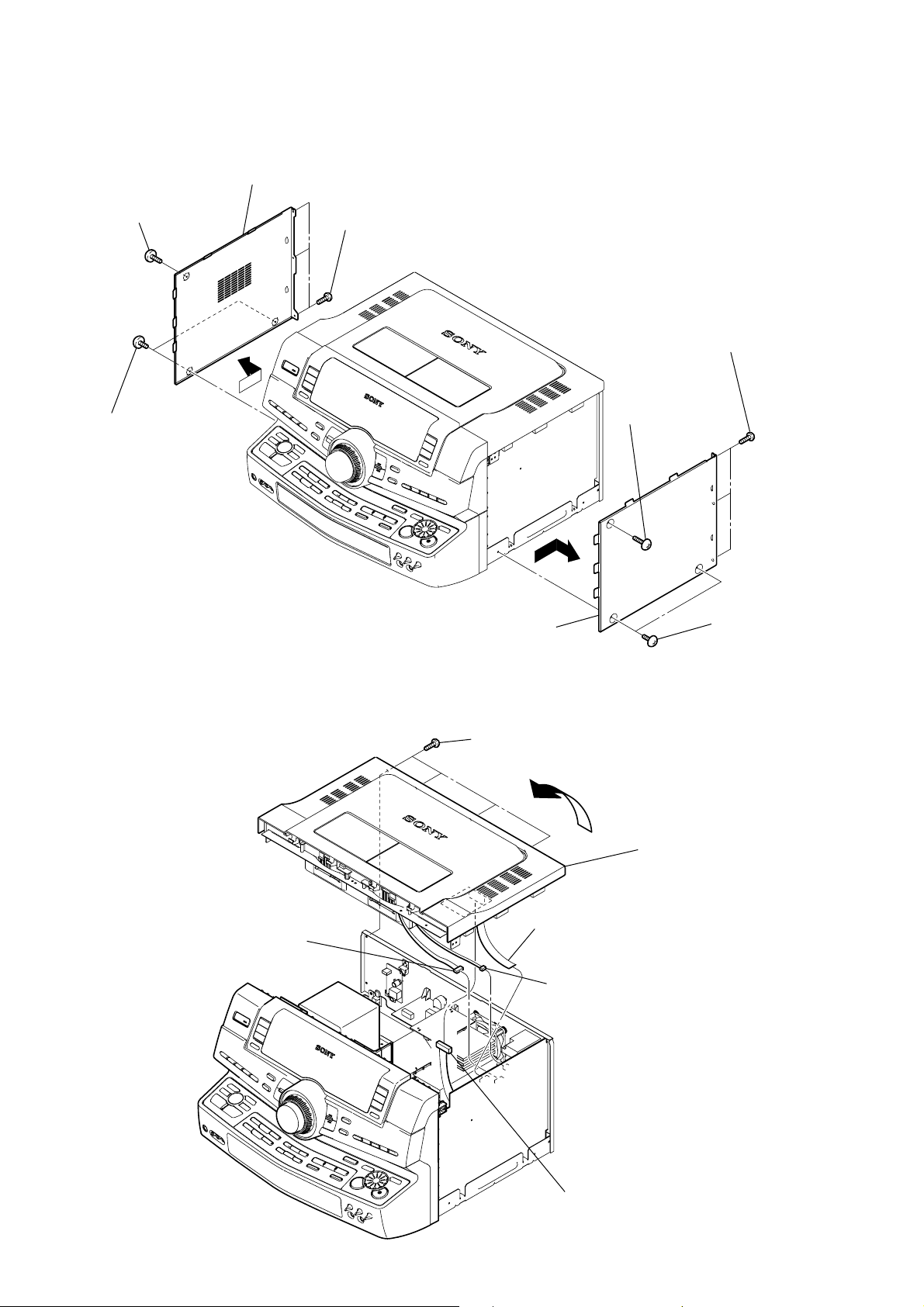
Note: Follow the disassembly procedure in the numerical order given.
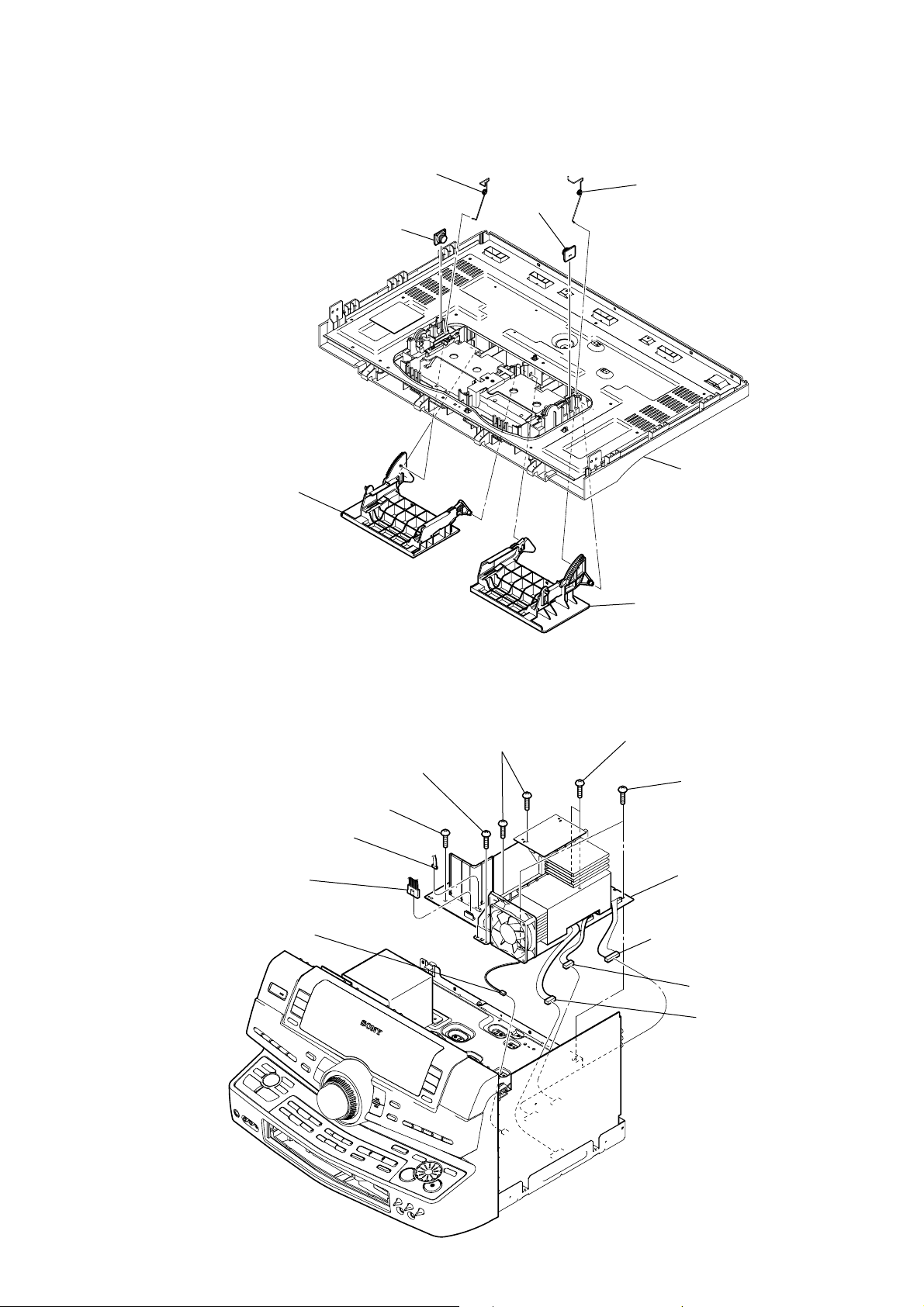
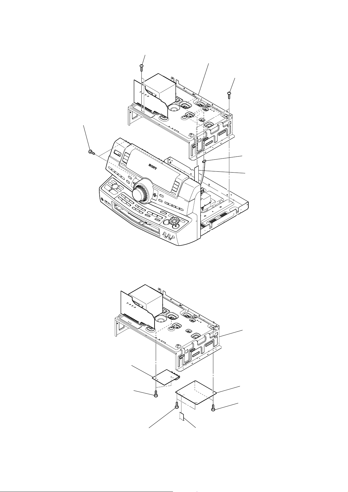
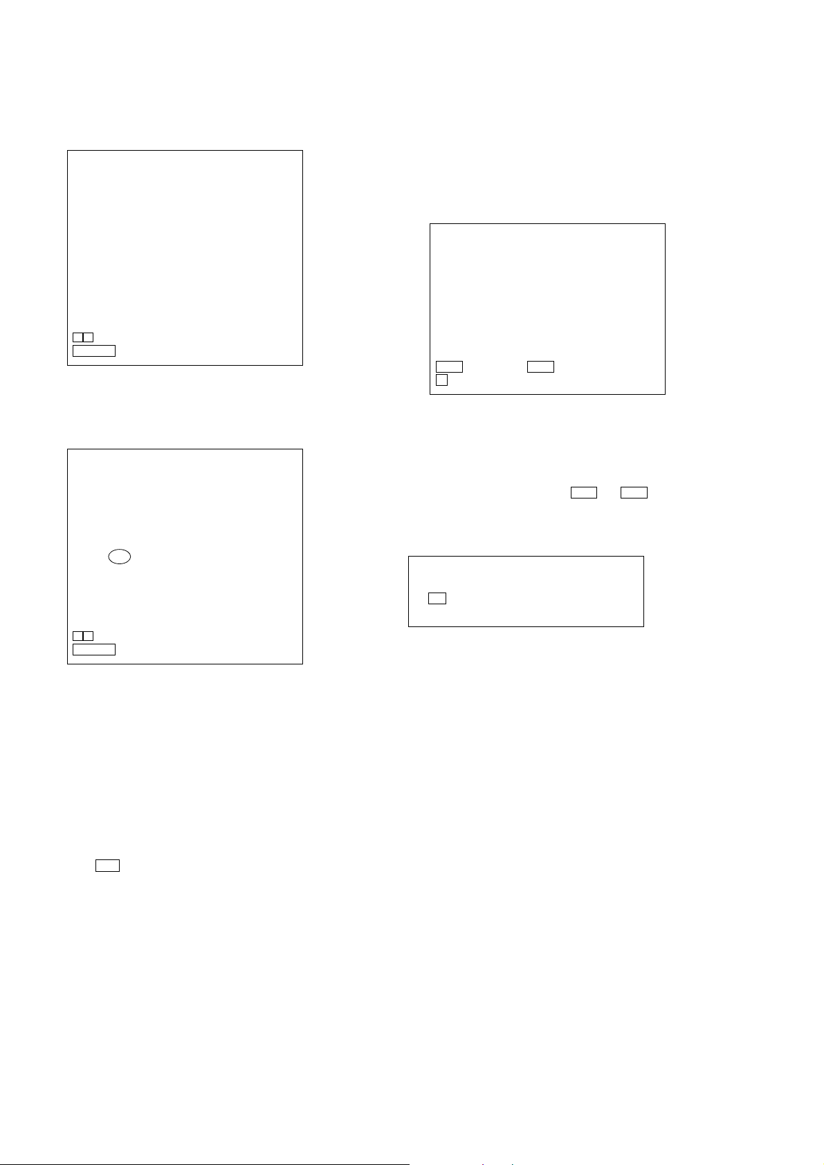
3-1. SIDE R PANEL, SIDE L PANEL
0
side L panel
7
screw
(case 3 TP2)
6
two
screws
(case 3 TP2)
9
8
three screws
(+BVTP 3
×
8)
3
three screws
(+BVTP 3
2
screw
(case 3 TP2)
×
8)
3-2. TOP CASE SECTION
6
CN380 (8P)
5
side R panel
1
four
screws
(+BVTP 3
2
4
×
8)
7
4
wire (flat type) (11 core)
(CN101)
CN381 (3P)
5
1
two
(case 3 TP2
top case section
screws
16
3
CN200 (6P)
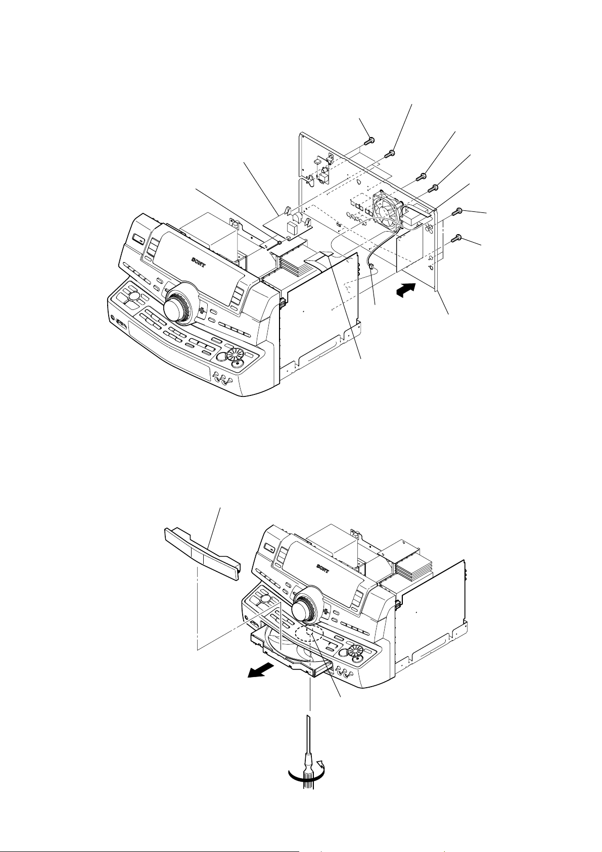
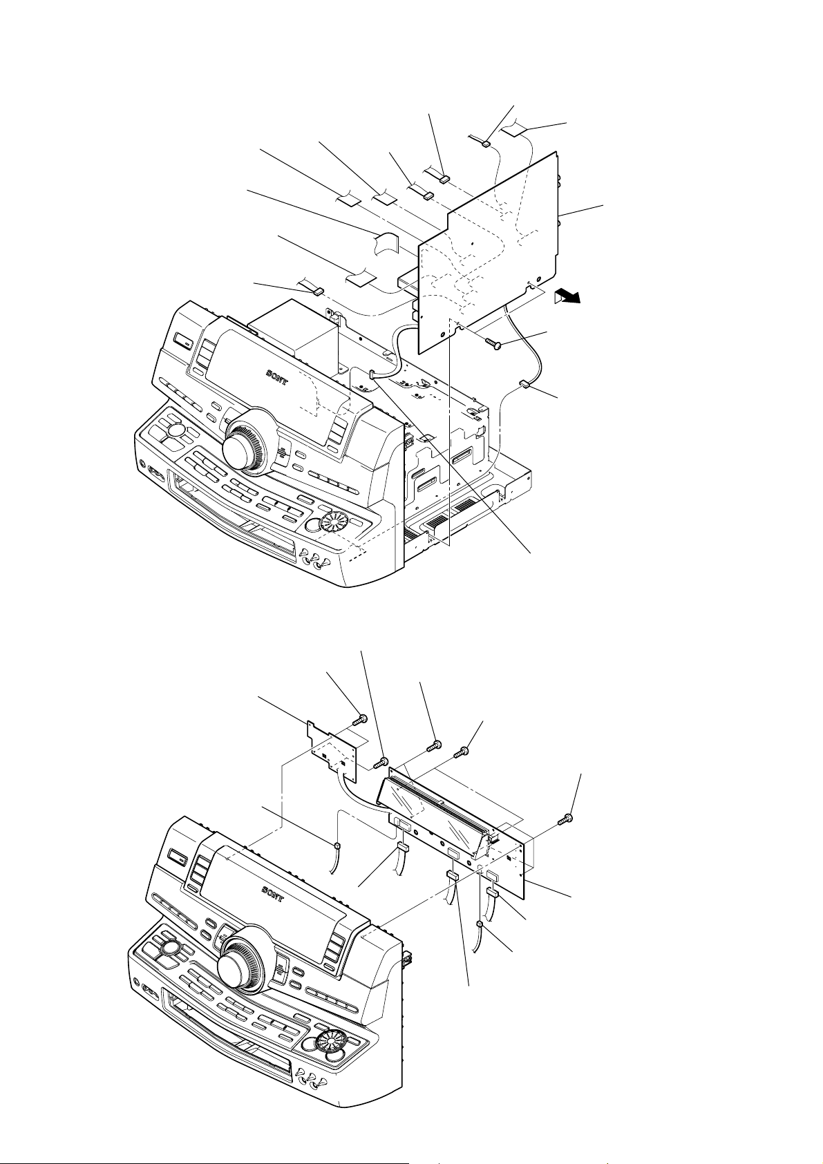
3-3. BACK PANEL SECTION
)
CN1200 (3P)
3
5
PRIMARY board
6
three
(+BVTP 3
screws
×
8)
qs
CN600 (2P)
4
two
(+BVTP 3
qa
screws
×
8)
7
three
(+BVTP 3
8
four
(+BVTP 3
1
wire (flat type) (9 core
(CN382)
0
(+BVTP 3
qd
back panel section
HCD-ZUX10D
screws
×
8)
screws
×
8)
9
three
four
screws
screws
×
8)
×
8)
(+BVTP 3
3-4. LOADING PANEL
3
loading panel
2
wire (flat type) (19 core)
(CN1502)
2
gear (shaft)
1
Turn the gear (shaft) in the direction of the arrow.
17
HCD-ZUX10D
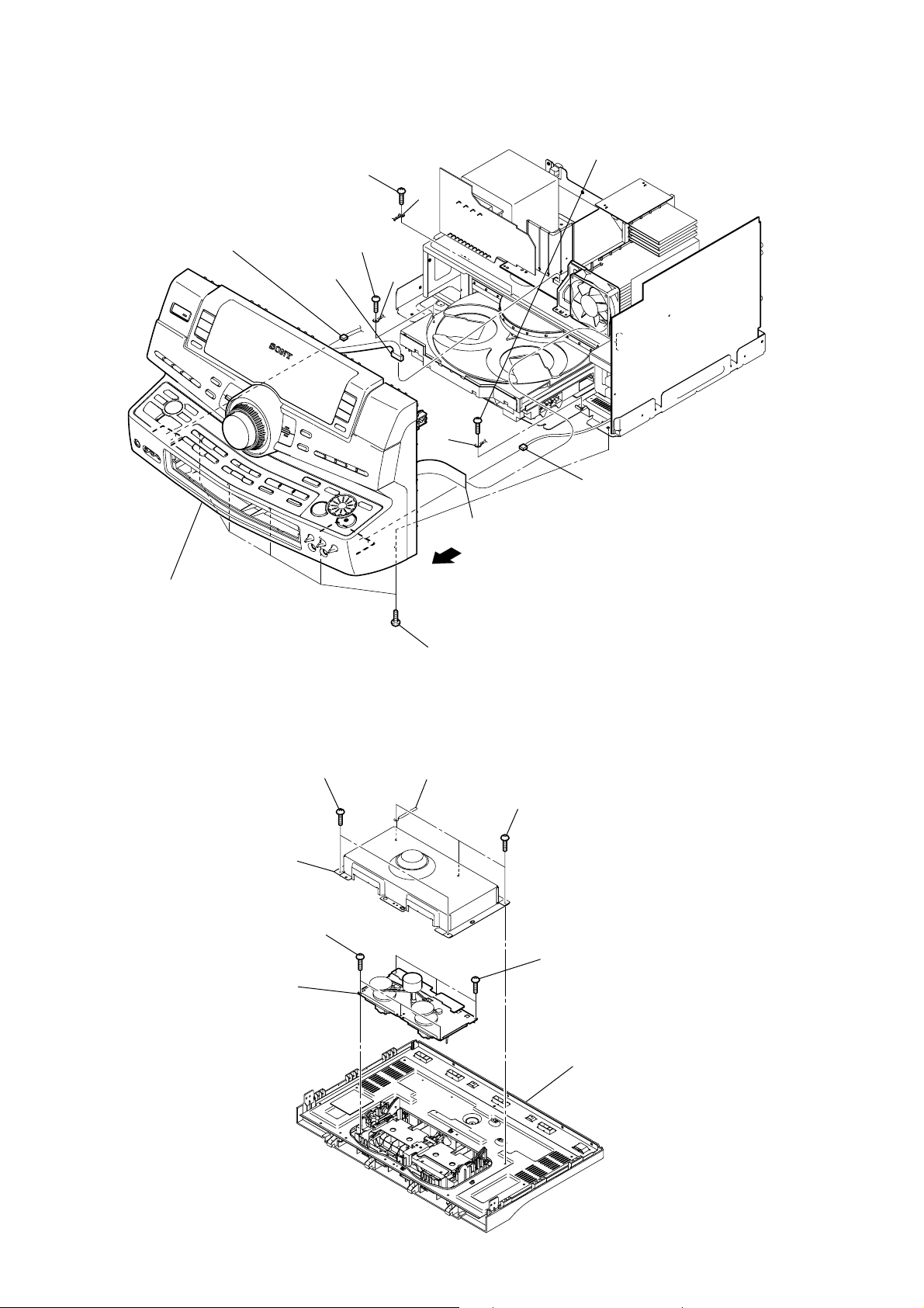
)
3-5. FRONT PANEL SECTION
9
CN901 (5P)
2
screw
(+BVTP 3
3
(+BVTP 3
5
CN602 (4P)
×
8)
screw
lug
4
screw
(+BVTP 3
lug
×
8)
lug
8
CN502 (5P)
×
8)
0
front panel section
3-6. TAPE MECHANISM DECK
2
(+BVTP 2.6 (3CR))
3
shild plate (TCM)
4
three
(+BVTP 2.6 (3CR))
6
tape mechanism deck
screws
two
screws
1
wire (flat type) (17 core)
(CN100)
7
6
five
screws
(+BVTP 3
wiring stopper
×
10)
1
three
(+BVTP 2.6 (3CR))
screws
5
three
(+BVTP 2.6 (3CR)
screws
18
top case assy
3-7. HOLDER (TC-L), HOLDER (TC-R)
y
n
5
4
damper
6
holder (TC-R)
spring (B)
1
damper
2
spring (A)
HCD-ZUX10D
top case ass
3-8. POWER AMP SECTION
3
screw
(+BVTP 3
2
CN602 (4P)
1
CN600 (6P)
0
CN582 (3P)
6
two
screws
(+BVTP 3
×
8)
3
holder (TC-L)
7
two
4
two
screws
8)
(+BVTP 3
×
×
8)
screws
(+BVTP 3
5
(+BVTP 3
qs
8
CN501 (12P)
×
8)
two
screws
×
8)
POWER AMP sectio
9
CN253 (9P)
qa
CN255 (5P)
19
HCD-ZUX10D
)
)
3-9. MAIN BOARD
5
(CN104)
1
wire (flat type) (17 core)
(CN100)
2
wire (flat type) (13 core)
(CN105)
wire (flat type) (13 core)
qs
CN550 (5P)
4
wire (flat type) (13 core)
(CN105)
qa
CN551 (5P)
8
CN251 (5P)
7
CN252 (2P)
9
(+BVTP 3
6
wire (flat type) (21 core
(CN521)
qf
MAIN board
0
two
screws
×
8)
qd
CN502 (5P)
3-10. FL BOARD, POWER LED BOARD
1
two
screws
(+BVTP 2.6 (3CR))
3
POWER LED board
qs
CN918 (3P)
2
two
screws
(+BVTP 2.6 (3CR))
4
two
(+BVTP 2.6 (3CR))
qa
CN902 (8P)
screws
5
two
screws
(+BVTP 2.6 (3CR))
9
3
CN1213 (8P)
8
CN905 (9P)
CN917 (3P)
6
four
screws
(+BVTP 2.6 (3CR)
7
FL board
20
0
CN906 (10P)
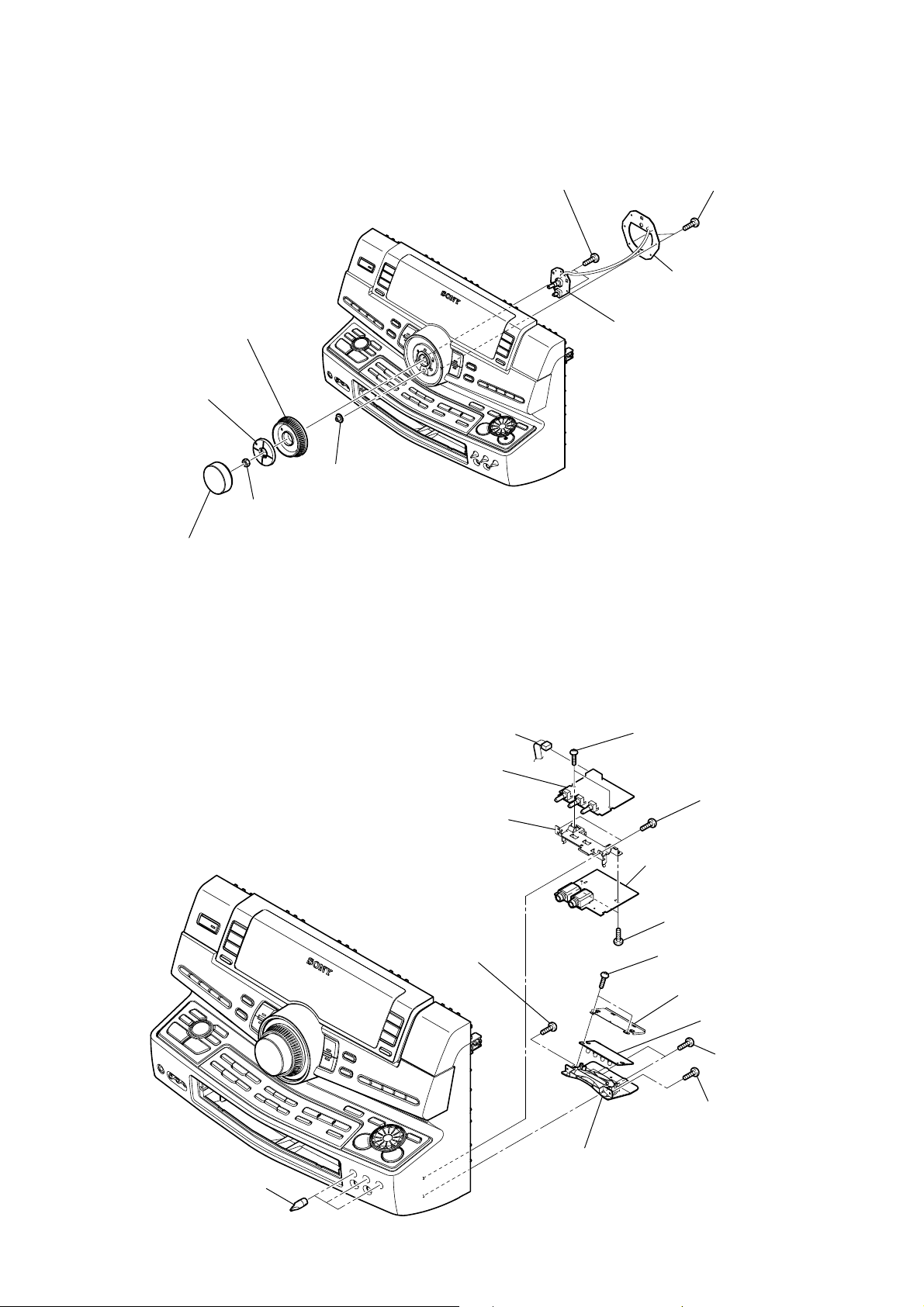
3-11. ILLUMINATION BOARD, VOL BOARD
4
knob (jog)
3
bracket (jog)
5
gear (encoder)
8
two
screws
(+BVTP 2.6 (3CR))
9
VOL board
HCD-ZUX10D
6
two
screws
(+BVTP 2.6 (3CR))
7
ILLUMINATION board
2
nut
1
knob (volume)
3-12. MIC BOARD, VR BOARD, BASE R LED BOARD
4
CN501 (6P)
5
VR board
8
bracket (MIC-jack)
qa
screw
(+BVTP 2.6 (3CR))
3
two
screws
(+BVTP 2.6 (3CR))
2
two
screws
(+BVTP 2.6 (3CR))
7
MIC board
6
two
screws
(+BVTP 2.6 (3CR))
qd
two
screws
(+BVTP 2.6 (3CR))
qf
sheild plate assy
1
three knobs (MIC)
qs
reflector (CD)
qg
BASE R LED board
9
two
screws
(+BVTP 2.6 (3CR))
0
screw
(+BVTP 2.6 (3CR))
21
HCD-ZUX10D
)
)
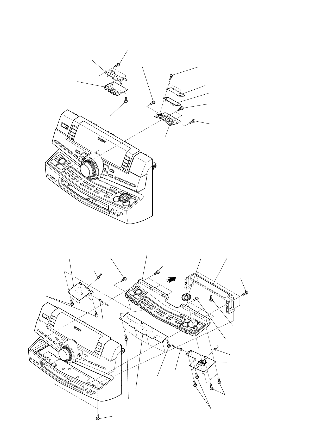
3-13. HP-VIDEO BOARD, BASE L LED BOARD
1
(+BVTP 2.6 (3CR))
two
screws
3
HP-VIDEO board
4
bracket
2
(+BVTP 2.6 (3CR))
two
screws
7
screw
(+BVTP 2.6 (3CR))
8
reflector (CD)
9
two
screws
(+BVTP 2.6 (3CR))
0
sheild plate assy
qa
BASE L LED board
5
two
screws
(+BVTP 2.6 (3CR))
6
screw
(+BVTP 2.6 (3CR)
3-14. CENTER KEY BOARD, BEAT CREATOR BOARD, X-ROUND BOARD
9
two
qd
BEAT CREATOR board
qa
four
screws
(+BVTP 2.6 (3CR))
screws
(+BVTP 2.6 (3CR))
5
CN956 (3P)
qs
CN908 (3P)
w;
(+BVTP 2.6 (3CR))
1
two
screws
(+BVTP 2.6 (3CR))
ws
CD escutcheon assy
7
(+BVTP 2.6 (3CR))
ql
four
(+BVTP 2.6 (3CR))
wa
CENTER KEY board
four
screws
three
qj
CN911 (3P)
screws
screws
0
qf
22
jog (X-round)
2
(+BVTP 2.6 (3CR))
3
(+BVTP 2.6 (3CR))
8
(+BVTP 2.6 (3CR)
qg
(+BVTP 2.6 (3CR))
qh
four
screws
(+BVTP 2.6 (3CR))
4
bracket (CD)
four
screws
screw
three
screws
6
CN907 (4P)
qk
X-ROUND board
four
screws
3-15. BRACKET (TRANS)
d
3
two screws
(+BVTP 3
×
HCD-ZUX10D
2
two screws
(+BVTP 3
8)
×
8)
6
bracket (trans)
1
two
screws
(+BV 3 (3-CR))
5
CN201 (6P)
4
wire (flat type) (24 core)
(CN101)
3-16. DMB16 BOARD, VIDEO BOARD
6
VIDEO board
5
two screws
(+BVTP 3
×
8)
3
two screws
(+BVTP 3
×
bracket (trans)
4
DMB16 boar
2
two screws
(+BVTP 3
1
wire (flat type) (3 core)
8)
(CN302)
×
8)
23
HCD-ZUX10D
k
d
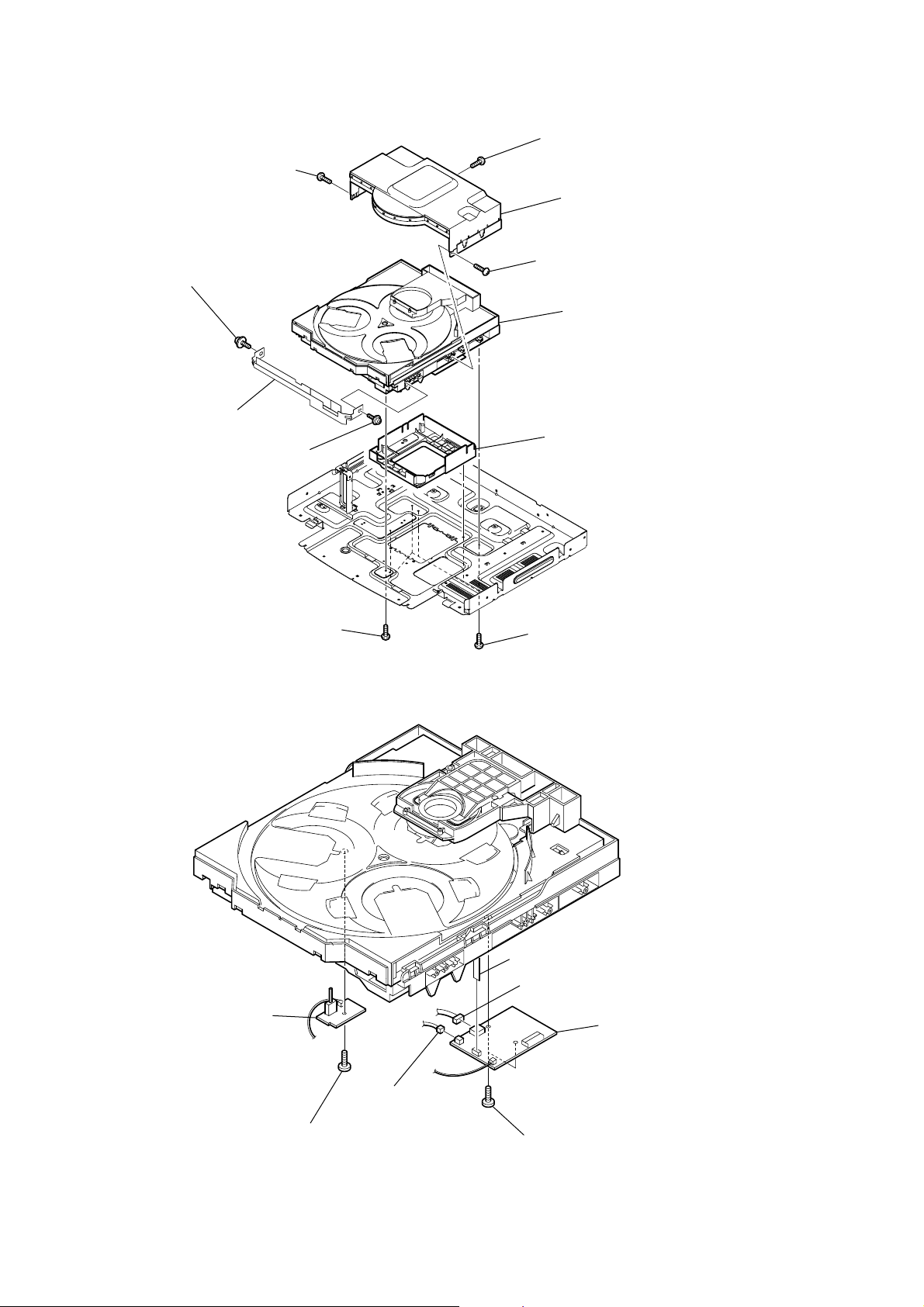
3-17. DVD MECHANISM DECK
5
screw
(+BVTP 3
9
BU fitting
0
dust sheet (bottom)
8
BU fitting
×
screw
10)
screw
6
screw
(+BVTP 3
7
CDM cover assy
4
screw
(+BVTP 3
qa
DVD mechanism dec
3
cover (BU)
×
×
10)
10)
1
screw
(+BVTP 3
3-18. DRIVER BOARD, SW BOARD
2
SWITCH board
×
10)
2
five screws
(+BVTP 3
7
CN702 (5core)
4
CN703 (4P)
×
10)
6
DRIVER boar
24
3
1
screw
(+BTTP (M2.6))
CN704 (2P)
5
two
screws
(+BTTP (M2.6))
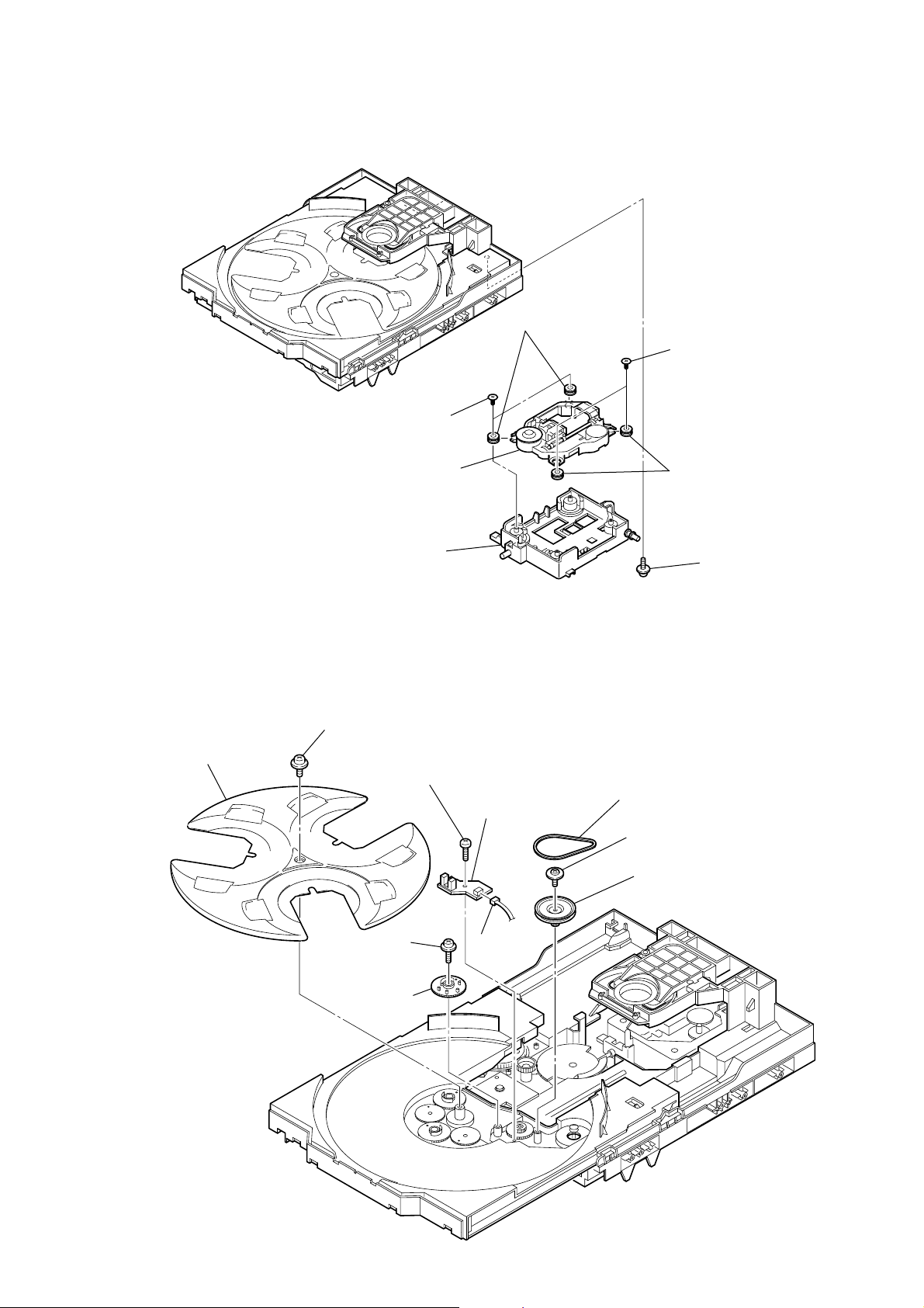
3-19. OPTICAL PICK-UP
)
3
two insulator screws
6
optical
pick-up
5
two insulators
2
two insulator screws
4
two insulators
HCD-ZUX10D
3-20. SENSOR BOARD
2
t
ray
7
holder (310)
1
floating
(+PTPWH M2.6)
6
floating
(+PTPWH M2.6)
7
g
screw
8
(+BTTP (M2.6))
screw
ear (geneva)
s
crew
0
SENSOR board
9
CN731
(3P)
1
(+PTPWH M2.6
3
b
elt (table)
4
floating
(+PTPWH M2.6)
5
screw
p
ulley (table)
floating
screw
25
HCD-ZUX10D
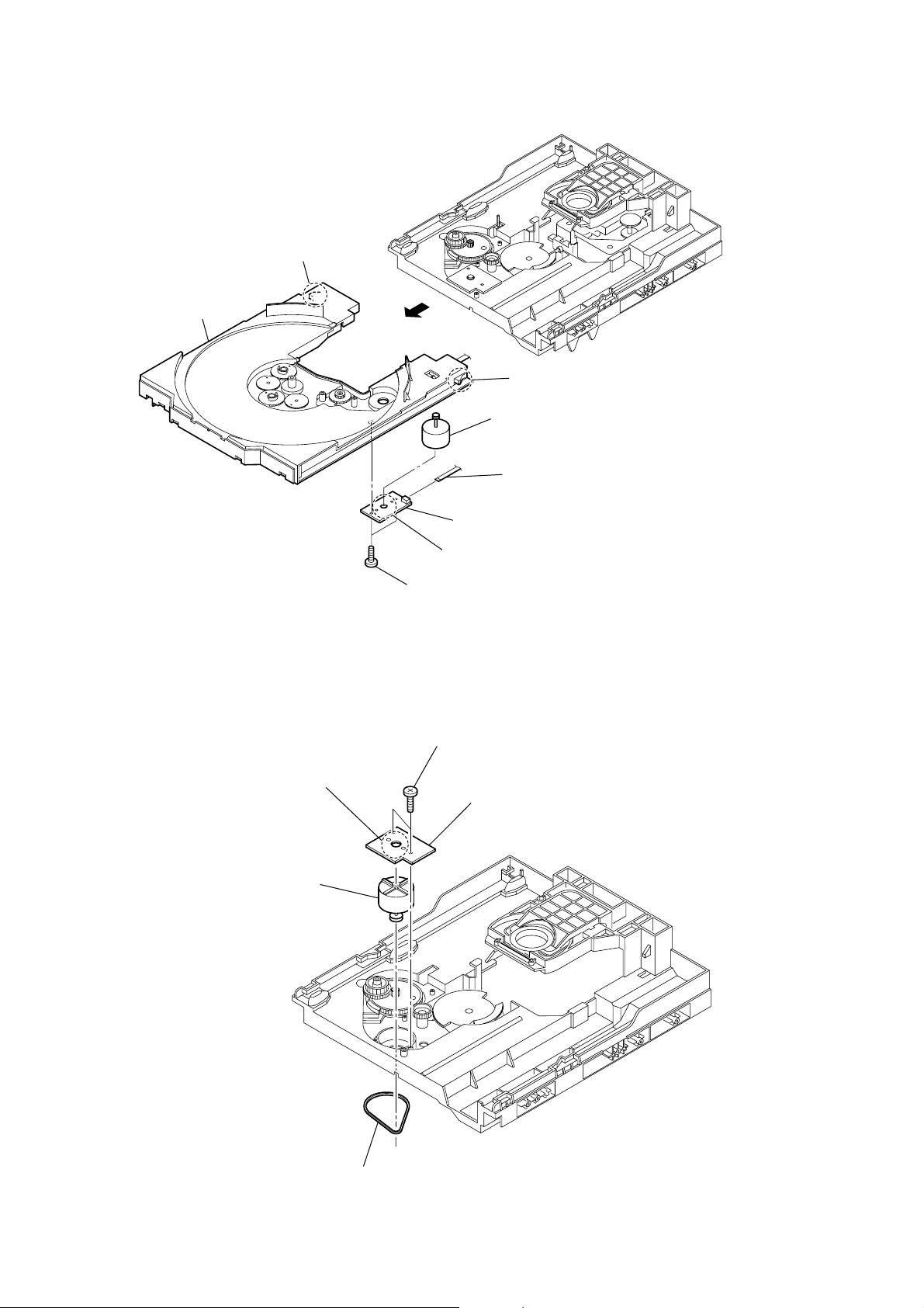
3-21. MOTOR (TB) BOARD
2
stopper
table
3-22. MOTOR (LD) BOARD
2
Remove the two solderings of motor.
4
8
6
Remove the two solderings of motor.
5
two
screws
(+BTTP (M2.6))
3
two
(+BTTP (M2.6))
stopper
1
7
t
able motor assy (M741)
3
wire (flat type) (5 core)
(CN742)
MOTOR (TB) board
screws
4
MOTOR (LD) board
26
5
l
oading motor assy (M751)
1
b
elt (loading)

SECTION 4
TEST MODE
HCD-ZUX10D
[PANEL TEST MODE]
• This mode is used to check the fluorescent indicator tube,
LEDs, keys, [MASTER VOLUME] jog, [OPERATION DIAL]
jog, [X-ROUND] jog, model, destination and software version.
Procedure:
1. Press @/1 button to turn on the system.
2. Press x button, [ENTER] button and [DISC 2] button
simultaneously.
3. All LEDs and segments in fluorescent indicator tube are lighted
up. All LEDs are lighted up. The POWER LED is lighted up
in red color.
4. When you want to enter to the software version display mode,
press [DISC 1] button. The model and destination are displayed.
5. During model and destination information display, press [DISC
1] button. Each time [DISC 1] button is pressed, the fluorescent
indicator tube shows the version and the software creation date
of each category software in the following sequence: MC
version, GC version, SYS version, DVD version, ST version,
TC version, TA version, TM version and return back to model
and destination information display.
6. Press [DISC 2] button, the key check mode is activated.
7. In the key check mode, the fluorescent indicator tube displays
“K 0 J0 V0 X0”.
Each time a button is pressed, “K” value increases. However,
once a button has been pressed, it is no longer taken into
account.
“V” value increases in the manner of 0, 1, 2, 3 ... if [MASTER
VOLUME] knob is turned clockwise, or it decreases in the
manner of 0, 9, 8,7 ... if [MASTER VOLUME] knob is turned
counterclockwise.
“J” value increases in the manner of 0, 1, 2, 3 ... if [OPERATION
DIAL] knob is turned clockwise, or it decreases in the manner
of 0, 9, 8,7 ... if [OPERATION DIAL] knob is turned
counterclockwise.
“X” value increases in the manner of 0, 1, 2, 3 ... if [X-ROUND]
knob is turned clockwise, or it decreases in the manner of 0,
9, 8,7 ... if [X-ROUND] knob is turned counterclockwise.
8. When [DISC SKIP/EX-CHANGE] button is pressed after all
LEDs and segments in fluorescent indicator tube light up,
alternate segments in fluorescent indicator tube and LEDs
would light up. If you press [DISC SKIP/EX-CHANGE] button
again, another half of alternate segments in fluorescent
indicator tube and LEDs would light up. Pressing [DISC SKIP/
EX-CHANGE] button again would cause all segments in
fluorescent indicator tube and LEDs light up.
9. To release from this mode, press three buttons in the same
manner as step 2, or disconnect the power cord.
• Check of Amplifier
1. Press [EQ BAND/MEMORY] button repeatedly until a message
“GEQ MAX” appears on the fluorescent indicator tube. The
GEQ increases to its maximum.
2. Press [EQ BAND/MEMORY] button repeatedly until a message
“GEQ MIN” appears on the fluorescent indicator tube. GEQ
decreases to its minimum.
3. Press [EQ BAND/MEMORY] button repeatedly until a message
“GEQ FLAT” appears on the fluorescent indicator tube. GEQ
is set to flat.
4. When the [MASTER VOLUME] knob is turned clockwise even
slightly, the sound volume increases to its maximum and a
message “VOLUME MAX” appears on the fluorescent
indicator tube.
5. When the [MASTER VOLUME] knob is turned counterclockwise
even slightly, the sound volume decreases to its minimum and
a message “VOLUME MIN” appears on the fluorescent
indicator tube.
•Tape function
1. When a tape is inserted in Deck B and recording is started, the
function is changed to TV automatically.
2. During recording, press
recording and the function is changed to TAPE B and rewind
the tape in Deck B until the recording start position and
playback of the tape in Deck B is started. If the [REC PAUSE/
START] button is pressed for a pause and pressed again to
resume recording during recording time, when the tape is
rewind, the tape will be rewind until the position where the
pause is applied.
•To release from Common Test mode
1. To release from this mode, press
2. The cold reset is enforced at the same time.
[COLD RESET]
• The cold reset clears all data including preset data stored in
the RAM to initial conditions. Execute this mode when
returning the set to the customer.
Procedure:
1. Press @/1 button to turn on the system.
2. Press x button, [ENTER] button, and @/1 button
simultaneously.
3. “COLD RESET” appears on the fluorescent indicator tube.
After that, the fluorescent indicator tube becomes blank for a
while, and the system is reset.
m/TUNING – will stop the
@/1 button.
[COMMON TEST MODE]
•This mode is used to check operations of the respective sections
of Amplifier and Tape.
Procedure:
•To enter Common Test Mode
1. Press
2. The DVD disc number indicators and TAPE A and B indicators
x button, [ENTER] button and [DISC 3] button
simultaneously.
flash on the fluorescent indicator tube. The function is changed
to TV and the volume is changed to VOLUME MIN.
[VACS ON/OFF]
•This mode is used to switch ON and OFF the VACS (Variable
Attenuation Control System).
Procedure:
1. Press @/1 button to turn on the system.
2. Press x button and [BEAM MODE] button simultaneously.
The message “VACS OFF” or “VACS ON” appears on the
fluorescent indicator tube.
27

HCD-ZUX10D
[TUNER STEP CHANGE]
•The step interval of AM channels can be toggled between 9
kHz and 10 kHz. This mode is not available for Saudi Arabian
and Russian models.
Procedure:
1. Press @/1 button to turn on the system.
2. Press [TUNER/BAND] button repeatedly to select the “AM”.
3. Press @/1 button to turn off the system.
4. Press [ENTER] button and @/1 button simultaneously. The
system turns on automatically. The message “AM 9K STEP”
or “AM 10K STEP” appears on the fluorescent indicator tube
and thus the channel step is changed.
[DVD TRAY LOCK MODE]
•This mode let you lock the disc tray. When this mode is
activated, the disc tray will not open when Z OPEN/CLOSE
button or [DISC SKIP/EX-CHANGE] button is pressed. The
message “LOCKED” will be displayed on the fluorescent
indicator tube.
Procedure:
1. Press @/1 button to turn on the system.
2. Select DVD function.
3. Press x button and Z OPEN/CLOSE button simultaneously
and hold down until “LOCKED” or “UNLOCKED” displayed
on the fluorescent indicator tube (around 5 seconds).
[DVD SHIP MODE (WITH MEMORY CLEAR)]
•This mode moves the optical pick-up to the position durable
to vibration and clears all data including preset data stored in
the RAM to initial conditions during the next AC-In. Use this
mode when returning the set to the customer after repair.
Procedure:
1. Press
2. Select DVD function.
3. Press x button, [DISC 1] button and @/1 button simultaneously
4. After the “STANDBY” blinking display finishes, a message
[DVD SHIP MODE (WITHOUT MEMORY CLEAR)]
•This mode moves the optical pick-up to the position durable
Procedure:
1. Press @/1 button to turn on the system.
2. Select DVD function.
3. Press [DVD] button and @/1 button simultaneously during
4. After the “STANDBY” blinking display finishes, a message
@/1 button to turn on the system.
during “DVD NO DISC” condition. The system turns off
automatically.
“MECHA LOCK” is displayed on the fluorescent indicator
tube and the DVD ship mode is set.
to vibration. Use this mode when returning the set to the
customer after repair.
“DVD NO DISC” condition. The system turns off
automatically.
“MECHA LOCK” is displayed on the fluorescent indicator
tube and the DVD ship mode is set.
[DVD COLOR SYSTEM]
• This mode let you change the color system of the video output
from PAL to NTSC or vice-versa. This mode is not available
for Latin American and Russian models.
Procedure:
1. Press
2. Select DVD function.
3. Press @/1 button again to turn off the system.
4. Press X button and @/1 button simultaneously. The system
[TCM OFFLINE MODE]
•This mode prevents the system from turning off automatically
Procedure:
1. When the system in turned off, press [EQ BAND/MEMORY]
2. The message “TCM OFFLINE” will be displayed on the
[REMOTE DISABLE MODE]
• This mode let you disable the remote commander reception.
Procedure:
1. Press
2. Press x button, [FLANGER] button and [DISC 2] button
[FACTORY PRESET]
•This mode is used to load all the factory use preset frequencies
Procedure:
1. Press @/1 button to turn on the system.
2. Press @/1 button, [TUNER/BAND] button and Z OPEN/CLOSE
•To release from Factory Preset Mode
To release from this mode, perform “COLD RESET”.
[VACS DISPLAY]
•This mode is used to check the VACS level.
@/1 button to turn on the system.
will turn on automatically.
The message “COLOR PAL” or “COLOR NTSC” appears on
the fluorescent indicator tube.
when TCM is not connected. Therefore, measurements can
be done even when TCM is not connected during production.
button, [DIRECTION] button and @/1 button simultaneously.
The system turns on automatically.
fluorescent indicator tube.
When this mode is activated, the system will not response if
the button on the remote commander is pressed. The message
“Remote Disable” appears on the fluorescent indicator tube.
This mode is essential for conducting test and repairing when
no interruption from the other remote commander is expected.
This mode is cancelled automatically when the system is turned
off.
@/1 button to turn on the system.
simultaneously until “Remote Disable” or “Remote Enable”
appears on the fluorescent indicator tube.
into FM 1-FM 20 and AM 1-AM 10. Originally, frequency of
FM 1-FM 20 and AM 1-AM10 are set to the minimum.
button simultaneously. The message “Factory” appears on the
fluorescent indicator tube. The function is changed to TUNER
automatically.
28
Procedure:
1. Press @/1 button to turn on the system.
2. Press x button, [DVD] button and [DISC SKIP/EX-CHANGE]
button simultaneously.
HCD-ZUX10D
Ver. 1.1
3. The fluorescent indicator tube displays “VATB F APC”.
“V” represents Conventional VACS (Triggered by signal level).
“T” represents Thermal VACS NEO (Triggered by
temperature).
“AP” represents APVACS (Abuse Protection VACS).
“A ” is the Conventional VACS level.
“B” is the Thermal VACS NEO level.
“C” is the APVACS level.
“F” is shown if the fan is triggered by software to turn in high
speed.
•To release from VACS display mode.
To release from this mode, do the step (2) again.
[TV/SAT SWITCHING]
•This mode let you switch from TV to SAT and vice-versa.
Procedure:
1. Press @/1 button to turn on the system.
2. Select TV function.
3. Press [TV/SAT] button and @/1 button simultaneously. The
function will change to SAT. Press the same buttons again to
change from SAT to TV.
[DVD FIRMWARE DISPLAY]
•This mode is used to display the DVD firmware version.
Procedure:
1. Press @/1 button to turn on the system.
2. Select DVD function.
3. Press
@/1 button again to turn off the system.
4. Press x button and @/1 button. The system turns on
automatically.
5. The version of DVD firmware appears on the on-screen display
on TV.
•To release from DVD Firmware Display Mode
To release from this mode, press @/1 button to turn off the system.
[DVD OFFLINE]
•When the DVD motherboard is not connected to the main unit,
the system would go into protector mode (caused by DVD
Power Monitor) automatically. DVD Offline mode is used to
prevent protector when the DVD motherboard is not connected.
Besides that, this mode is used to enable audio output from
the function other than DVD function in order to check the
audio output from the system when the DVD motherboard is
not connected.
Procedure:
1. After turn on the power supply (the system is turned off), press
x button, [FLANGER] button and [DISC 1] button simultaneously.
The system will turn on automatically.
2. The message “DVD OFFLINE” will appears on the fluorescent
indicator tube.
•To release from DVD Offline Mode
To release from this mode, perform “COLD RESET” or turn off
the power supply.
[DVD SERVICE MODE]
•This mode let you make diagnosis and adjustment easily by
using the remote commander and the TV. The instructions,
diagnostic results, etc. are given on the on-screen display.
• TEST DISC LIST
Be sure to use the DVD disc that matches the signal standards of
your region.
•CD
YEDS-18 (Part No.: 3-702-101-01)
PATD-012 (Part No.: 4-225-203-01)
•DVD SL (Single Layer)
NTSC : HLX-503 (Part No.: J-6090-069-A)
HLX-504 (Part No.: J-6090-088-A)
PAL : HLX-506 (Part No.: J-6090-077-A)
•DVD DL (Dual Layer)
NTSC : HLX-501 (Part No.: J-6090-071-A)
HLX-505 (Part No.: J-6090-089-A)
PAL : HLX-507 (Part No.: J-6090-078-A)
• Procedure to enter to DVD Service Mode:
1. Press @/1 button to turn on the system.
2. Select DVD function.
3. Press x button and Z OPEN/CLOSE button simultaneously
and then turn the [MASTER VOLUME] knob clockwise.
4. The message “SERVICE IN” appears on the fluorescent
indicator tube and the Top Menu of Remocon Diagnosis Menu
appears on the on-screen display on the TV. The model name,
main unit’s micom version information (IF-con) and DVD
firmware version information (Syscon) are displayed at the
bottom of the on-screen display.
Remocon Diagnosis Menu
0. External Chip Check
1. Servo Parameter Check
2. Drive Manual Operation
3. Emergency History
4. Version Information
Model Name : LUX11D_ME
IF-con : V
Syscon : Ver.
er. 01.00 (0000)
1.200
5. To execute each function, press its number by using numeric
button on the remote commander.
6. To release from this mode, press
@/1 button to turn off the
system.
•Execute IOP Measurement
In order to execute IOP measurement, the following standard
procedures must be followed.
1. From the Top Menu of Remocon Diagnosis Menu, select “2.
Drive Manual Operation” by pressing the [2] button on the
remote commander. The following screen appears on the onscreen display.
Drive Manual Operation
1. Servo Control
2. Track/Layer Jump
3. Manual Adjustment
4. Mecha test mode
5. MIRR time Adjust
0. Return to Top Menu
29
HCD-ZUX10D
Ver. 1.1
2. Select “3. Manual Adjustment” by pressing the [3] button on
the remote commander. The following screen appears on the
on-screen display.
Manual Adjust
1. Track Balance Adjust:
2. Track Gain Adjust:
3. Focus Balance Adjust:
4. Focus Gain Adjust:
5. Eg Boost Adjust:
6. lop:
7. TRV. Level:
8. S curve(FE) Level:
9. RFL(PI) Level:
0. MIRR Time:
O o Change Value
RETURN Return to previous menu
3. Select “6. Iop:” by pressing [6] button on the remote
commander.
4. Wait until a hexadecimal number appears in the on-screen
display as below:
Manual Adjust
1. Track Balance Adjust:
2. Track Gain Adjust:
3. Focus Balance Adjust:
4. Focus Gain Adjust:
5. Eg Boost Adjust:
6. Iop. ED:
7. TRV. Level:
8. S curve(FE) Level:
9. RFL(PI) Level:
0. MIRR Time:
• Check Emergency History
To check the emergency history, please follow the following
procedure.
1. From the Top Menu of Remocon Diagnosis Menu, select “3.
Emergency History” by pressing the [3] button on the remote
commander. The following screen appears on the on-screen
display.
Emg. History Check
Laser Hours CD 999h 59min
1. 01 05 04 04
00 00 00 00 00 00 23 45
2. 02 02 01 01 00 A9 4B 00
00 00 00 00 00 00 23 45
Next Next Page Prev Prev Page
O Return to Top Menu
DVD 999h 59min
00 92 46 00
2. You can check the total time when the laser is turned on during
playback of DVD and CD from the above menu. The maximum
time, which can be displayed are 999h 59min.
3. You can check the error code of latest 10 emergency history
from the above menu. To view the previous or next page of
emergency history, press . or > on the remote
commander. The error code consists of
• Error Code
Example of Error code
1. 01 05 04 04 00 92 46 00
00 00 00 00 00 00 23 45
O o Change Value
RETURN Return to previous menu
5. Convert data from hexadecimal to decimal by using conversion
table.
6. Please find the label on the rear of the BU (Base Unit).
The default IOP value is written in the label.
7. Subtract between these two values.
8. If the remainder is smaller than 93 (decimal), then it is OK.
However if the value is higher than 93, then the BU is defective
and need to be change.
9. Press [RETURN] button on the remote commander to return to
previous menu.
10. Press [0] button on the remote commander to return to the Top
Menu of Remocon Diagnosis Menu.
11. Press
@/1 button to turn off the system.
The meaning of error code is as below:
01: Communication error (No reply from syscon)
02: Syscon hung up
03: Power OFF request when syscon hung up
19: Thermal shutdown
24: MoveSledHome error
25: Mechanical move error (5 Changer)
26: Mechanical move stack error
30: DC motor adjustment error
31: DPD offset adjustment error
32: TE balance adjustment error
33: TE sensor adjustment error
34: TE loop gain adjustment error
35: FE loop gain adjustment error
36: Bad jitter after adjustment
40: Focus NG
42: Focus layer jump NG
52: Open kick spindle error
51: Spindle stop error
60: Focus on error
61: Seek fail error
62: Read Q data/ID error
70: Lead in data read fail
71: TOC read time out (CD)
80: Can’t buffering
81: Unknown media type
30
 Loading...