

Sony HCDRG-77 Service manual
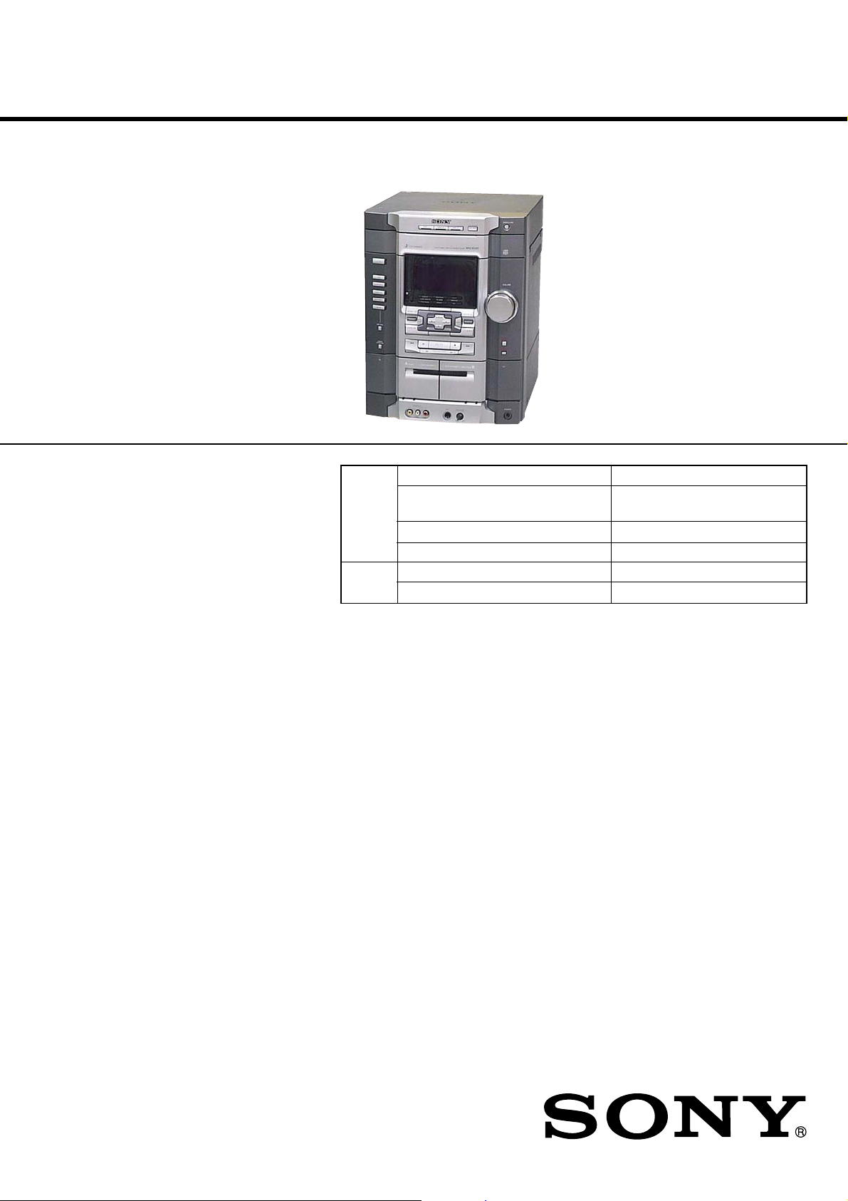
HCD-GX8000/RG77
SERVICE MANUAL
Ver 1.2 2004.08
HCD-GX8000/RG77 are the amplifier, CD
player, tape deck and tuner section in
MHC-GX8000/RG77.
Model Name Using Similar Mechanism NEW
CD
Section
TAPE
Section
CD Mechanism Type
Base Unit Name BU-30BD60C
Optical Pick-up Name A-MAX.3
Model Name Using Similar Mechanism NEW
Tape T ransport Mechanism T ype TCM-230AWR41CS
US Model
HCD-GX8000
E Model
HCD-RG77
CDM58E-30BD60C (HCD-GX8000)
CDM58ES-30BD60C (HCD-RG77)
AUDIO POWER SPECIFICATIONS
(HCD-GX8000 only)
POWER OUTPUT AND TOTAL
HARMONIC DISTORTION:
With 6-ohm loads, both channels driven, from
120 Hz - 10 kHz; rates 200 watts per channel
minimum RMS power, with no more than 10%
total harmonic distortion from 250 miliwatts to
rated output.
Amplifier section
HCD-GX8000
Total harmonic distortion
HCD-RG77
The following are measured at AC 120, 220, 240V
50/60 Hz
DIN power output (rated) 160 + 160 watts
Continuous RMS power output (reference)
Inputs
GAME (VIDEO): 1 Vp-p, 75 ohms
(phono jack)
GAME (AUDIO): Voltage 250 mV,
(phono jacks) impedance 47 kilohms
MD/VIDEO (AUDIO) IN: voltage 450 mV/250 mV,
(phono jacks) impedance 47 kilohms
MIC: sensitivity 1 mV,
(phone jack) impedance 10 kilohms
Outputs
VIDEO OUT: max. output level 1 Vp-p,
(phono jacks) unbalanced, Sync.
Less than 0.1 % (6 ohms
at 1 kHz, 100 W)
(6 ohms at 1 kHz, DIN)
200 + 200 watts
(6 ohms at 1 kHz,
10% THD)
negative load impedance
75 ohms
SPECIFICATIONS
PHONES: accepts headphones of
(stereo mini jack) 8 ohms or more
FRONT SPEAKER: accepts impedance of 6 to
SURROUND SPEAKER: accepts impedance of
CD player section
System Compact disc and digital
Laser Semiconductor laser
Laser Output Max. 44.6 µW*
Frequency response 2 Hz – 20 kHz (±0.5 dB)
Wave length 795 nm
CD OPTICAL DIGITAL OUT
(Square optical connector jack, rear panel)
Wave length 660 nm
Output Level –18 dBm
Tape player section
Recording system 4-track 2-channel stereo
Frequency response 50 – 13,000 Hz (±3 dB),
16 ohms
24 ohms or more
audio system
(λ=795nm)
*This output is the value
measured at a distance of
200 mm from the
objective lens surface on
the Optical Pick-up Block
with 7 mm aperture.
using Sony TYPE I
cassette
COMPACT DISC DECK RECEIVER
Tuner section
FM stereo, FM/AM superheterodyne tuner
FM tuner section
Tuning range 87.5 – 108.0 MHz
Antenna FM lead antenna
Antenna terminals 75 ohm unbalanced
Intermediate frequency 10.7 MHz
AM tuner section
Tuning range
Latin and North American models:
Middle Eastern models: 531 – 1,602 kHz
Other models: 531 – 1,602 kHz
Antenna AM loop antenna
Antenna terminals External antenna terminal
Intermediate frequency 450 kHz
530 – 1,710 kHz
(with the interval set at 10
kHz)
531 – 1,710 kHz
(with the interval set at 9
kHz)
(with the interval set at 9
kHz)
(with the interval set at 9
kHz)
530 – 1,710 kHz
(with the interval set at 10
kHz)
– Continued on next page –
9-873-542-03 Sony Corporation
2004H05-1 Audio Group
C 2004.08 Published by Sony Engineering Corporation
HCD-GX8000/RG77
r
General
Power requirements
North America and Mexican models:
Argentina model: 220 V AC, 50/60 Hz
Other models: 120 V, 220 V or 230 - 240
Power consumption 240 watts
Dimensions (w/h/d) Approx. 280 x 360 x 445
Mass : Approx. 11.0 kg
Design and specifications are subject to change
without notice.
120 V AC, 60 Hz
V AC, 50/60 Hz
Adjustable with voltage
selector
mm
SAFETY CHECK-OUT
After correcting the original service problem, perform the following safety check before releasing the set to the customer:
Check the antenna terminals, metal trim, “metallized” knobs,
screws, and all other exposed metal parts for AC leakage.
Check leakage as described below.
LEAKAGE TEST
The A C leaka ge from an y e xposed metal part to earth ground and
from all exposed metal parts to any exposed metal part having a
return to chassis, must not exceed 0.5 mA (500 microamperes.).
Leakage current can be measured by any one of three methods.
1. A commercial leakage tester, such as the Simpson 229 or RCA
WT -540A. Follo w the manufacturers’ instructions to use these
instruments.
2. A battery-operated A C milliammeter. The Data Precision 245
digital multimeter is suitable for this job.
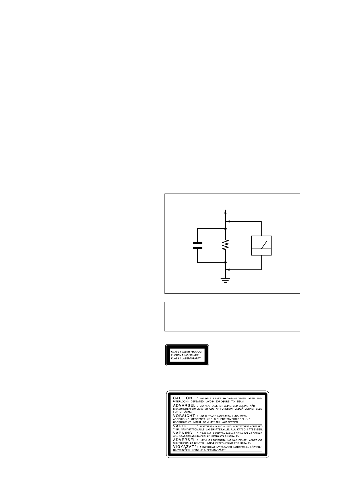
3. Measuring the voltage drop across a resistor by means of a
VOM or battery-operated AC voltmeter. The “limit” indication is 0.75 V, so analog meters must have an accurate lowvoltage scale. The Simpson 250 and Sanwa SH-63Tr d are e xamples of a passive VOM that is suitable. Nearly all battery
operated digital multimeters that have a 2 V A C range are suitable. (See Fig. A)
To Exposed Metal
Parts on Set
Notes on chip component replacement
• Never reuse a disconnected chip component.
• Notice that the minus side of a tantalum capacitor may be dam-
aged by heat.
Flexible Circuit Board Repairing
• Keep the temperature of the soldering iron around 270 ˚C during repairing.
• Do not touch the soldering iron on the same conductor of the
circuit board (within 3 times).
• Be careful not to apply force on the conductor when soldering
or unsoldering.
1.5 k
0.15 µF
Fig. A. Using an AC voltmeter to check AC leakage.
Ω
Earth Ground
AC
voltmete
(0.75 V)
CAUTION
Use of controls or adjustments or performance of procedures
other than those specified herein may result in hazardous radiation exposure.
This appliance is classified as
a CLASS 1 LASER product.
The CLASS 1 LASER
PRODUCT MARKING is
located on the rear exterior.
The following caution label is located inside the unit.
SAFETY-RELATED COMPONENT WARNING!!
COMPONENTS IDENTIFIED BY MARK 0 OR DOTTED
LINE WITH MARK 0 ON THE SCHEMATIC DIAGRAMS
AND IN THE PARTS LIST ARE CRITICAL TO SAFE
OPERATION. REPLACE THESE COMPONENTS WITH
SONY PARTS WHOSE PART NUMBERS APPEAR AS
SHOWN IN THIS MANUAL OR IN SUPPLEMENTS PUBLISHED BY SONY.
2

TABLE OF CONTENTS
HCD-GX8000/RG77
Ver 1.1
1. SERVICING NOTES ................................................ 4
2. GENERAL
Location of Controls ....................................................... 5
Setting the Clock............................................................. 6
3. DISASSEMBLY
3-1. Disassembly Flow ........................................................... 7
3-2. Top Case .......................................................................... 8
3-3. Loading Panel .................................................................. 8
3-4. CD Mechanism Deck ...................................................... 9
3-5. Front Panel Section ......................................................... 9
3-6. Back Panel Section .......................................................... 10
3-7. MAIN Board ................................................................... 10
3-8. Base Unit (BU-30BD60C) .............................................. 11
3-9. DRIVER Board, MOTOR Board and
SENSOR (CD) Board ..................................................... 11
3-10. Tape Mechanism Deck (TCM-230AWR41CS).............. 12
3-11. Belt .................................................................................. 12
3-12. SW Board, HEAD (A) Board and HEAD (B) Board..... 13
4. TEST MODE.............................................................. 14
5. MECHANICAL ADJUSTMENTS....................... 18
6. ELECTRICAL ADJUSTMENTS
Deck section .................................................................... 18
CD Section ...................................................................... 21
7-25. Printed Wiring Boards
– MAIN TRANS/SUB-TRANS Boards –...................... 46
7-26. Schematic Diagram
– MAIN TRANS/SUB-TRANS Boards –...................... 47
7-27. IC Pin Function Description ........................................... 49
8. EXPLODED VIEWS
8-1. Panel Section ................................................................... 53
8-2. Front Panel Section ......................................................... 54
8-3. Chassis Section ............................................................... 55
8-4. CD Mechanism Deck Section ......................................... 56
8-5. Base Unit Section (BU-30BD60C) ................................. 57
8-6. Tape Mechanism Deck Section
(TCM-230AWR41CS) .................................................... 58
9. ELECTRICAL PARTS LIST ............................... 59
7. DIAGRAMS
7-1. Block Diagram – CD SERVO Section – ....................... 23
7-2. Block Diagram – TUNER/TAPE DECK Section – ...... 24
7-3. Block Diagram – MAIN Section – ................................ 25
7-4. Block Diagram – DISPLAY/KEY CONTROL/
POWER SUPPLY Section – ........................................... 26
7-5. Note for Printed Wiring Boards and
Schematic Diagrams ....................................................... 27
7-6. Printed Wiring Board – BD Board – ............................. 28
7-7. Schematic Diagram – BD Board – ................................ 29
7-8. Printed Wiring Boards
– DRIVER/MOTOR/SENSOR (CD) Boards –.............. 30
7-9. Schematic Diagram
– DRIVER/MOTOR/SENSOR (CD) Boards –.............. 30
7-10. Printed Wiring Boards
– SW/HEAD (A)/HEAD (B) Boards – .......................... 31
7-11. Schematic Diagram – SW Board –................................ 32
7-12. Printed Wiring Board – MAIN Board – ........................ 33
7-13. Schematic Diagram – MAIN Board (1/4) – .................. 34
7-14. Schematic Diagram – MAIN Board (2/4) – .................. 35
7-15. Schematic Diagram
– MAIN (3/4)/HEAD (A)/HEAD (B) Boards – ............. 36
7-16. Schematic Diagram – MAIN Board (4/4) – .................. 37
7-17. Printed Wiring Board – GAME IN Board – .................. 38
7-18. Schematic Diagram – GAME IN Board –..................... 39
7-19. Printed Wiring Boards
– POWER/SENSOR Boards –........................................ 40
7-20. Schematic Diagram – POWER/SENSOR Boards – ..... 41
7-21. Printed Wiring Boards
– PANEL/CD OPEN/CD SWITCH Boards – ................ 42
7-22. Schematic Diagram
– PANEL/CD OPEN/CD SWITCH Boards – ................ 43
7-23. Printed Wiring Boards
– PAD SWITCH/VOL Boards –..................................... 44
7-24. Schematic Diagram – PAD SWITCH/VOL Boards –... 45
3
HCD-GX8000/RG77
SECTION 1
SERVICING NOTES
NOTES ON HANDLING THE OPTICAL PICK-UP
BLOCK OR BASE UNIT
The laser diode in the optical pick-up block may suffer electrostatic break-down because of the potential difference generated
by the charged electrostatic load, etc. on clothing and the human
body.
During repair, pay attention to electrostatic break-down and also
use the procedure in the printed matter which is included in the
repair parts.
The flexible board is easily damaged and should be handled with
care.
NOTES ON LASER DIODE EMISSION CHECK
The laser beam on this model is concentrated so as to be focused
on the disc reflective surface by the objective lens in the optical
pick-up block. Therefore, when checking the laser diode emission, observe from more than 30 cm away from the objectiv e lens.
LASER DIODE AND FOCUS SEARCH OPERATION
CHECK
Carry out the “S curve check” in “CD section adjustment” and
check that the S curve waveforms is output three times.
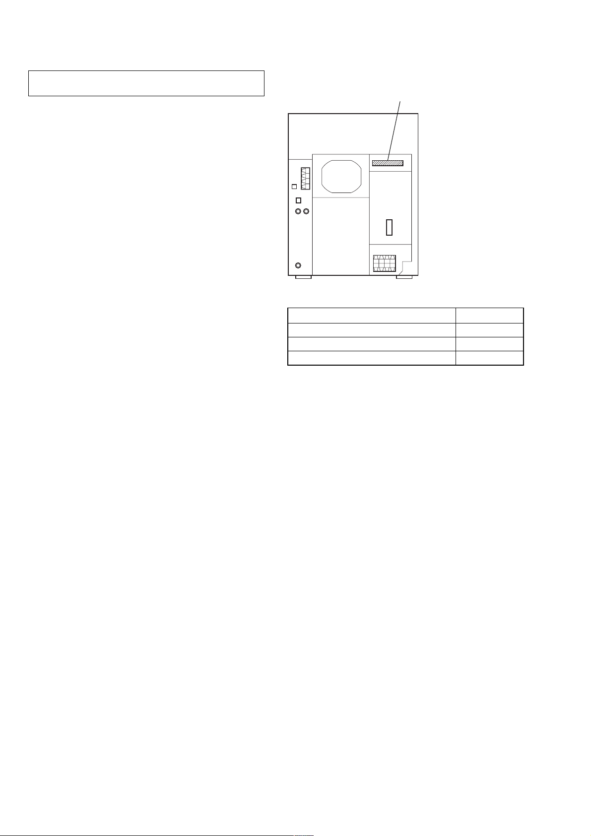
• MODEL IDENTIFICATION
– Back Panel –
PART No.
MODEL PART No.
E, Singapore, Chilean and Peruvian models 4-237-780-1
Mexican and Argentina models 4-237-780-6
US model 4-237-780-9
[]
[]
[]
4
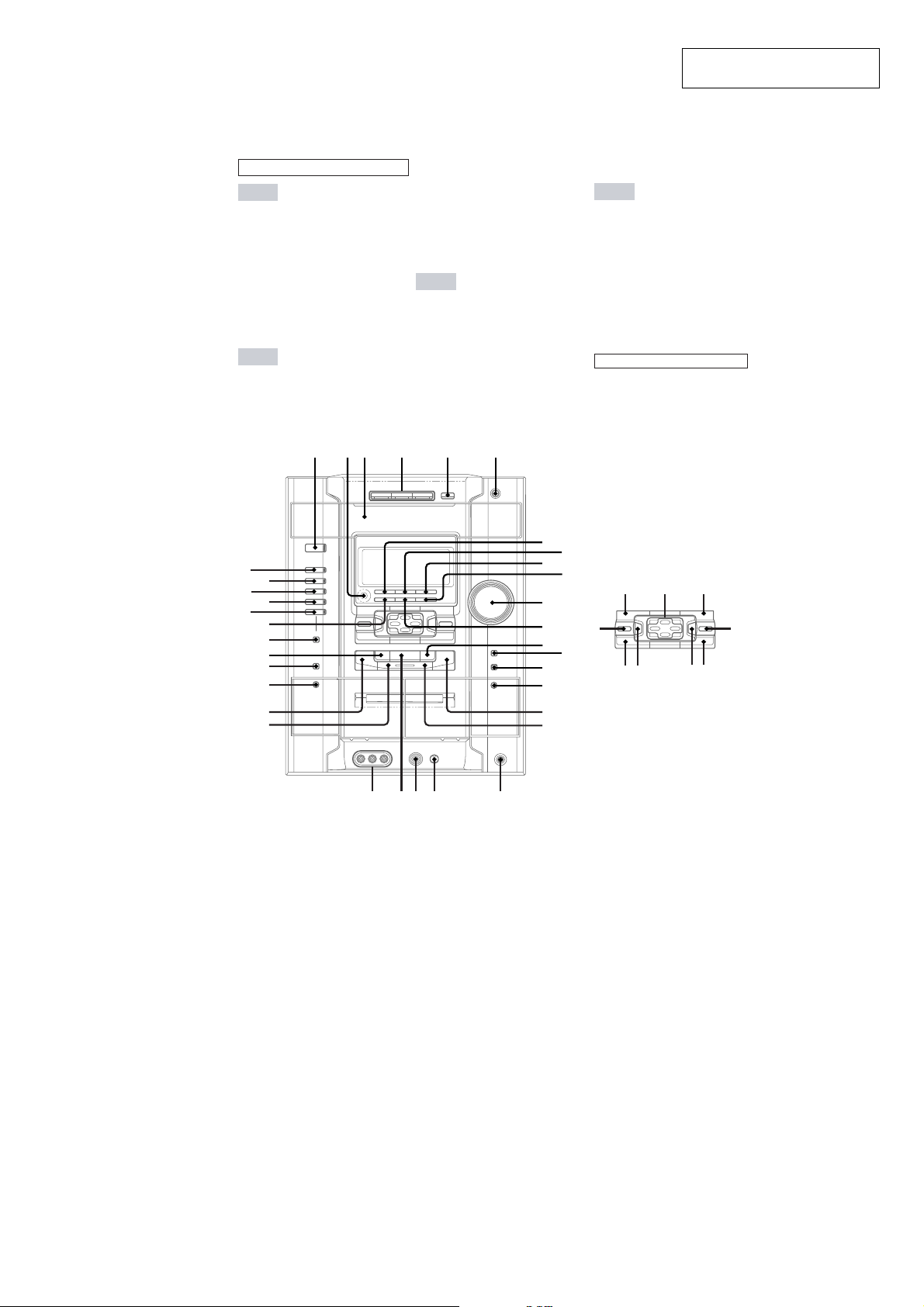
LOCATION OF CONTROLS
q
w;waw
W
– Front Panel –
ALPHABETICAL ORDER
A - D
CD eg
CD SYNC HI-DUB qf
DECK A A wh
DECK B A qh
DIMMER 9
DIRECTION q;
DISC 1~3 4
DISC SKIP EX-CHANGE 5
Disc tray 3
DISPLAY 7
E - L
EDIT q;
EFFECT ON/OFF rs
ENTER ra
FM MODE qs
1
23 4
SECTION 2
GENERAL
GAME ea
GAME EQ rd
GAME INPUT wd
GAME MIXING wl
GROOVE rf
IR (receptor) 2
M - Q
MD (VIDEO) es
MIC wa
MIC LEVEL w;
MOVIE EQ ek
MUSIC EQ eh
OPEN/CLOSE Z 6
P FILE r;
PHONES (jack) ql
PLAY MODE e;
56
HCD-GX8000/RG77
This section is extracted from
instruction manual.
R - Z
REC PAUSE/START qg
REPEAT qs
SPECTRUM 8
SURROUND el
SURROUND SPEAKER MODE
wj
TAPE A/B ed
TUNER/BAND ef
TUNER MEMORY e;
VOLUME qa
BUTTON DESCRIPTIONS
@/1 1
hH ws
x qd
X wk
> qj
. wg
M/+ qk
m/– wf
v/V/b/B ej
eg
ed
ea
ef
es
e;
wl
wk
wj
wh
wg
X
7
8
9
0
K
L
rf
M
N
O
qh
qj
qk
s
l
rdrs
ek
ejeh
el
r;
ra
5
HCD-GX8000/RG77
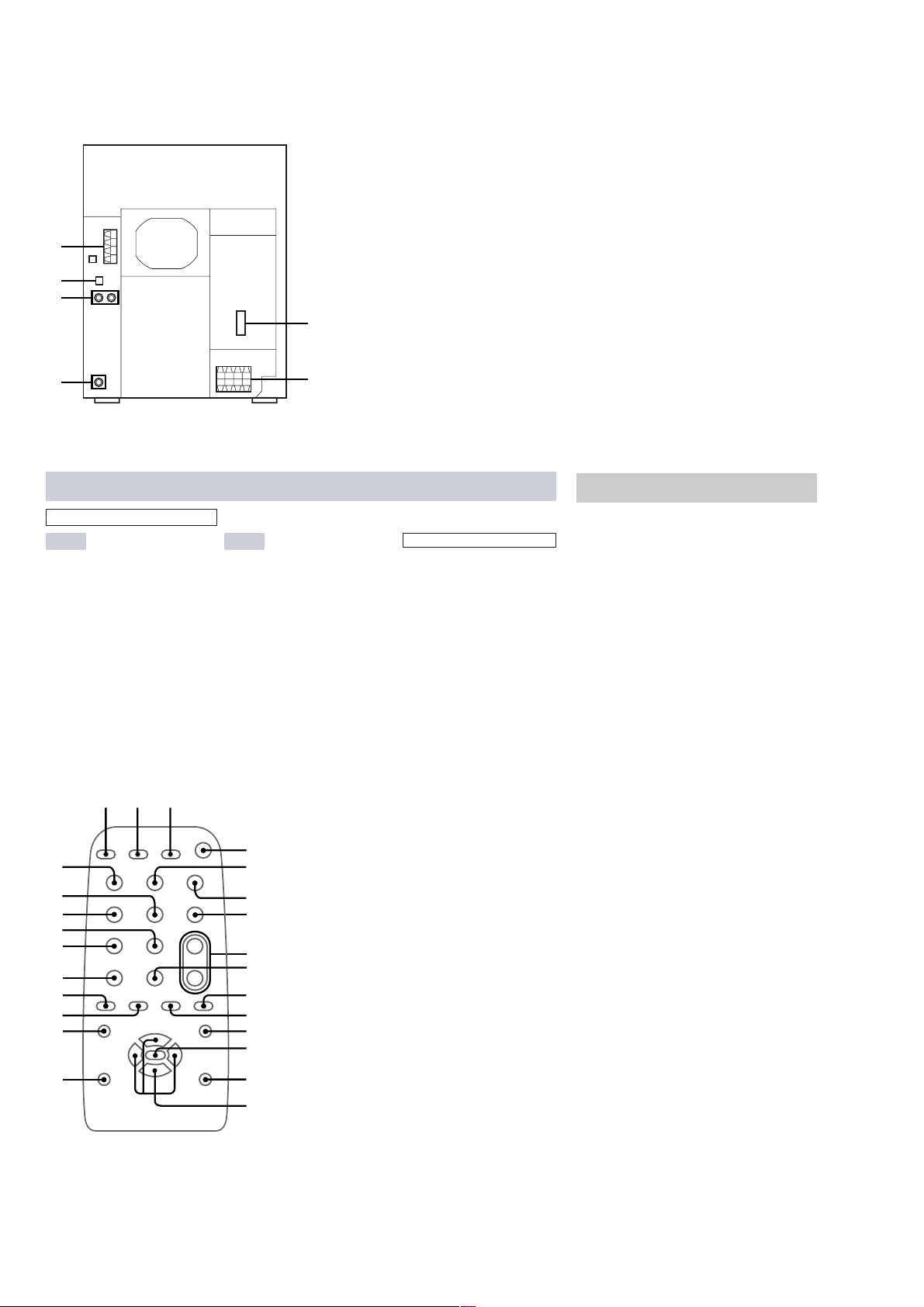
– Back Panel –
1
2
3
1 ANTENNA terminal
2 CD DIGITAL OUT OPTICAL terminal
3 MD/VIDEO (AUDIO) IN jack
4 VIDEO OUT jack
5 FRONT/SURROUND SPEAKER terminal
6 VOLTAGE SELECTOR switch
(E and Singapore models)
6
4
Remote Control
ALPHABETICAL ORDER
A - M P - Z
CD ql
CLEAR 7
CLOCK/TIMER SELECT 2
CLOCK/TIMER SET 3
D.SKIP 9
ENTER qd
EFFECT ON/OFF qf
GAME w;
MD (VIDEO) q;
ABC
Y
X
W
V
U
T
S
R
qj
PRESET – wd
PRESET + wf
PRESET EQ qj
P FILE qh
SURROUND SPEAKER MODE
qs
SURROUND qs
SLEEP 1
TAPE A/B qa
TUNER/BAND qk
TUNING – wa
TUNING + ws
VOL +/– 8
D
E
6
7
8
9
q;
qa
qs
qd
5
BUTTON DESCRIPTIONS
@/1 4
hH wg
X 5
x 6
. wd
> wf
m wa
M ws
v/V/b/B qg
Setting the clock
1
Turn on the system.
2
Press CLOCK/TIMER SET on the
remote.
When you set the time for the first time,
proceed to step 5.
3
Press V or v repeatedly to select
CLOCK SET.
4
Press ENTER.
5
Press V or v repeatedly to set the hour.
6
Press ENTER.
7
Press V or v repeatedly to set the
minute.
8
Press ENTER.
The clock starts functioning.
Tip
If you have made a mistake or want to change the
time, start over from step 2.
Note
The clock settings are canceled when you disconnect
the power cord or if a power failure occurs.
6
qh
qf
qg
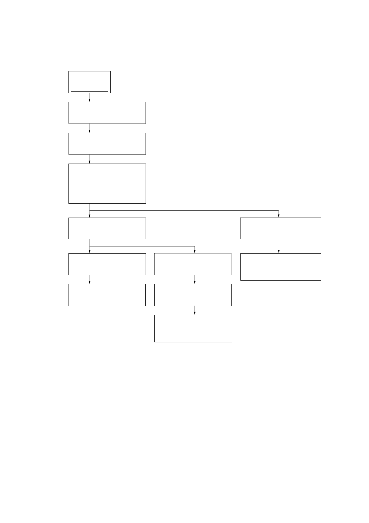
• This set can be disassembled in the order shown below.
3-1. DISASSEMBLY FLOW
SET
3-2. TOP CASE
(Page 8)
3-3. LOADING PANEL
(Page 8)
3-4. CD MECHANISM DECK
(CDM58E-30BD60C:
HCD-GX8000)
(CDM58ES-30BD60C:
HCD-RG77)
(Page 9)
SECTION 3
DISASSEMBLY
HCD-GX8000/RG77
Ver 1.1
3-5. FRONT PANEL SECTION
(Page 9)
3-6. BACK PANEL SECTION
(Page 10)
3-7. MAIN BOARD
(Page 10)
3-10.TAPE MECHANISM DECK
(TCM-230AWR41CS)
(Page 12)
3-11.BELT
(Page 12)
3-12.SW BOARD,
HEAD (A) BOARD AND
HEAD (B) BOARD
(Page 13)
3-8. BASE UNIT (BU-30BD60C)
(Page 11)
3-9. DRIVER BOARD,
MOTOR BOARD AND
SENSOR (CD) BOARD
(Page 11)
7
HCD-GX8000/RG77
)
Note: Follow the disassembly procedure in the numerical order given.
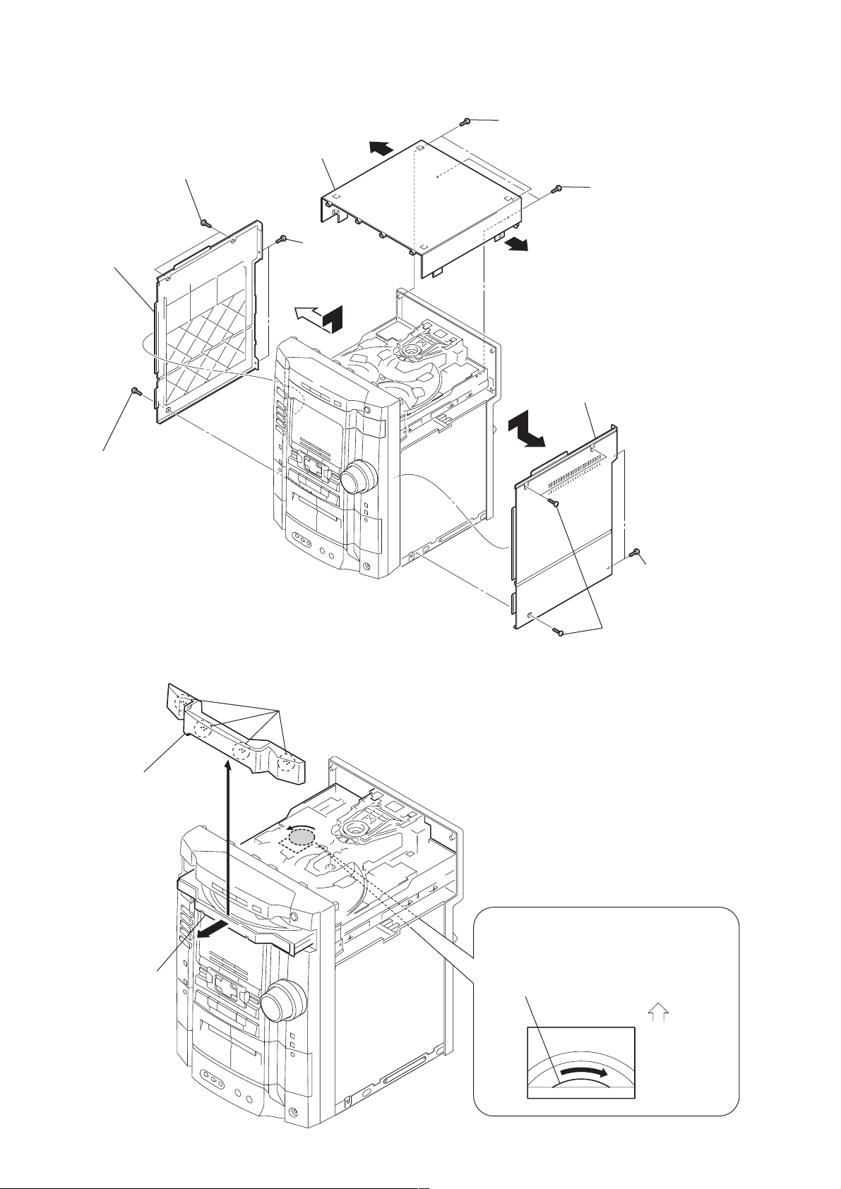
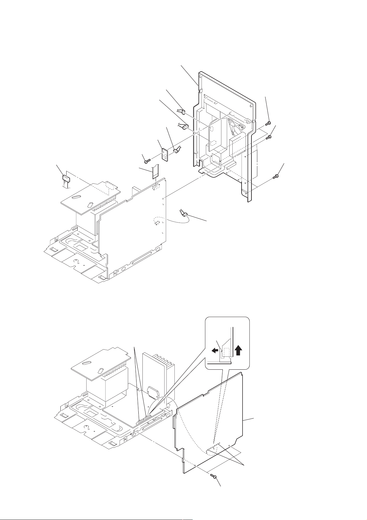
3-2. TOP CASE
two screws (case 3 TP2)
4
6
side panel (L)
q;
top
case
5
(BVTP 3
9
two screws
×
10)
7
two screws
(BVTP 3
9
×
10)
3
side panel (R)
8
two screws
(BVTP 3
×
12)
4
screw (case 3TP2)
3-3. LOADING PANEL
4
loading panel
3
four claws
2
two
screws
(BVTP 3
1
three screws (case 3 TP2
×
10)
2
Pull-out the disc table.
8
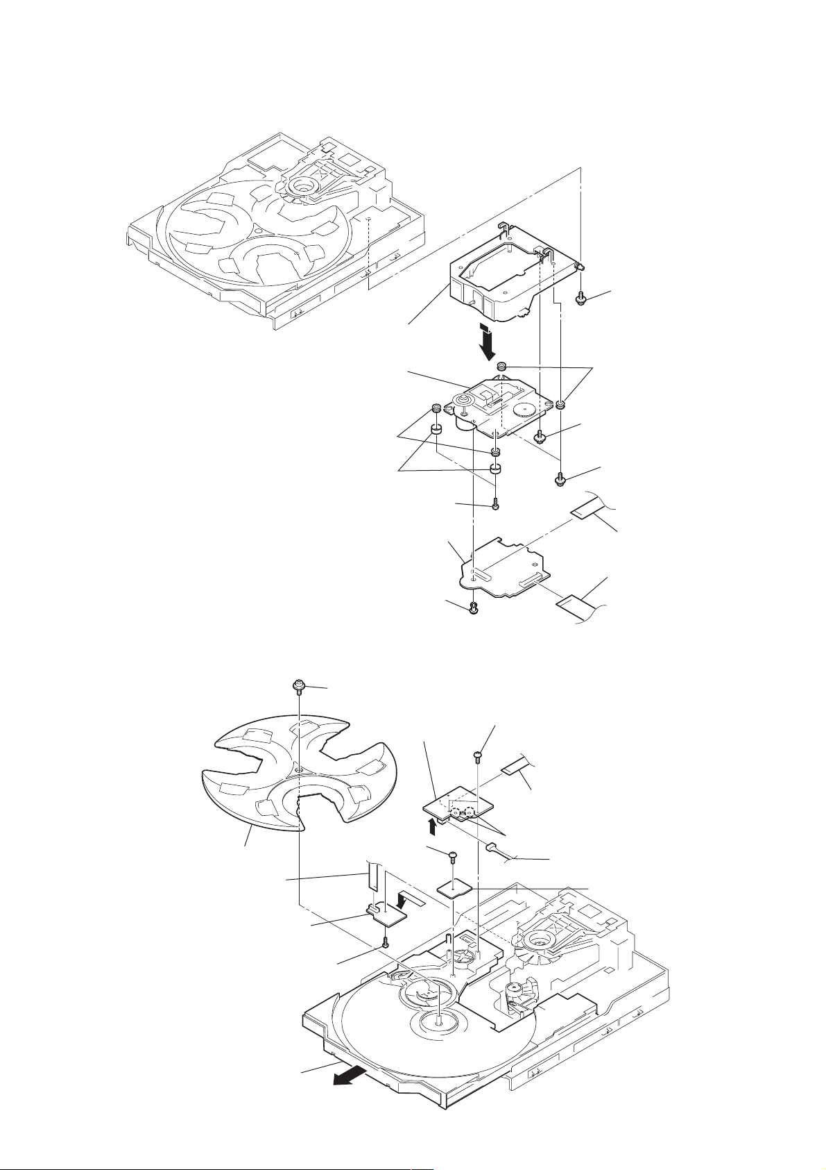
–BOTTOM VIEW–
CD mechanism deck (CDM58E-30BD60C)
1
Turn the pulley in the direction of the arrow.
Front panel side
HCD-GX8000/RG77
)
Ver 1.1
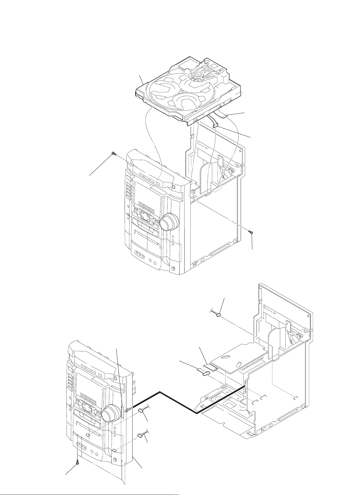
3-4. CD MECHANISM DECK (CDM58E-30BD60C: HCD-GX8000), (CDM58ES-30BD60C: HCD-RG77)
5
CD mechanism deck
1
wire (flat type)
3
screw
(BVTP 3
(21 core)
2
× 10)
(CN201
connector
(
CN202)
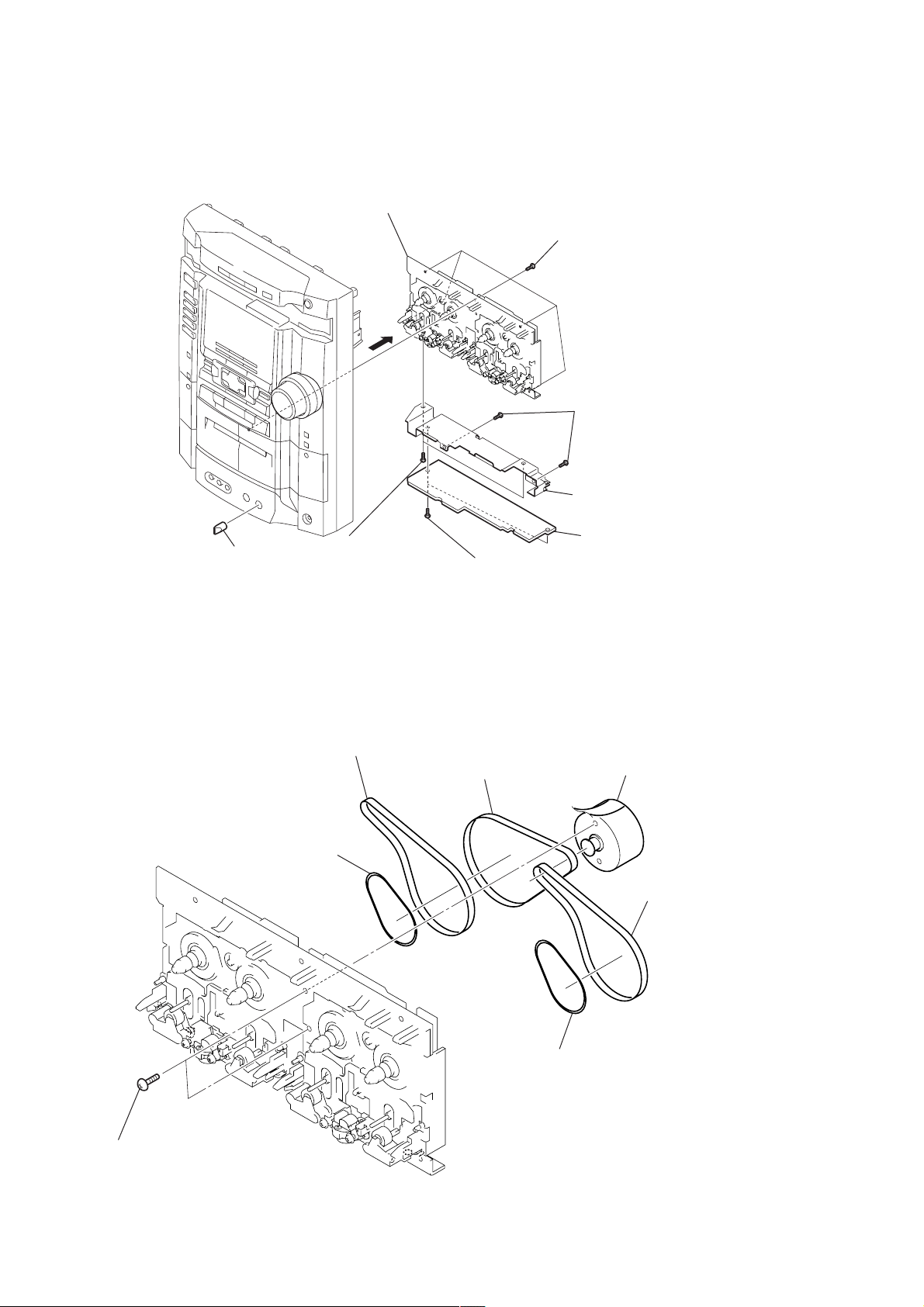
3-5. FRONT PANEL SECTION
4
connector
CN401)
(
2
connector
CN781)
(
1
wire (flat type)
(17 core)
(CN304)
2
connector
CN783)
(
3
screw
(BVTP 3
× 10)
3
four
(BVTP 3
screws
× 10
2
connector (
2
connector (
5
front panel section
)
CN1)
CN2)
9
HCD-GX8000/RG77
)
)
3-6. BACK PANEL SECTION
5
connector (CN973)
1
wire
(flat type) (11core)
(CN702)
5
connector
5
connector
4
2
screw
(BVTP 3
(CN974)
connector
3
sensor board
×
10)
(CN976)
(CN701)
7
back panel section
6
two
screws
(BVTP 3
6
three
(BVTP 3
6
(BVTP 3
×
10)
screws
four
×
10)
screws
×
10
3-7. MAIN BOARD
3
two
claws
5
connector
claw
(CN891)
main board
10
2
two
(CN502, CN503
1
two screws (BVTP 3
4
main board
connectors
×
10)
)
3-8. BASE UNIT (BU-30BD60C)
qs
two insulators (BU-30)
2
holder (BU) (BU-30) assy
qd
base unit (BU-30BD60C)
qa
HCD-GX8000/RG77
1
screw (PTPWH M2.6)
qs
two insulators (BU-30)
q;
screws (DIA. 12)
8
two stoppers (BU)
7
two screws (BVTP 2.6
6
BD board
5
rivet
×
8)
3-9. DRIVER BOARD, MOTOR BOARD AND SENSOR (CD) BOARD
qs
qd
3
wire (flat type)
(8 core)
tray
(CN702)
screw (PTPWH 2.6
qf
screw (BVTP 2.6
0
×
motor board
7
×
8)
8)
6
two screws (BVTP 2.6
5
8
wire (flat type)
(8 core)
Remove the two solderings of motor.
9
9
3
×
8)
(CN721)
connector
qg
sensor (CD)
two
screws (PTPWH M2.6
4
wire (flat type)
(16 core)
wire (flat type)
(21 core)
(CN722)
(CN102)
(CN101)
board
4
driver board
1
s
crew (BVTP 2.6
qa
Pull out the disc table.
×
2
8)
11
HCD-GX8000/RG77
)
)
3-10. TAPE MECHANISM DECK (TCM-230AWR41CS)
8
tape mechanism deck
(TCM-230AWR41CS)
3
2
five
screws
(BVTP 2.6
2
two
screws
(BVTP 2.6
×
8)
×
8)
3-11. BELT
1
knob (mic)
5
belt
(FR)
6
two
(P 2.6
4
belt
screws
×
3)
(capstan B)
4
two
screws
(BVTP 2.6
3
belt
(capstan C)
×
7
8)
shield plate (TC
5
game in board
2
motor assy
(M901)
4
belt
(capstan B)
(capstan
12
1
two
screws
(PS 2.6
×
5
belt
(FR)
5)
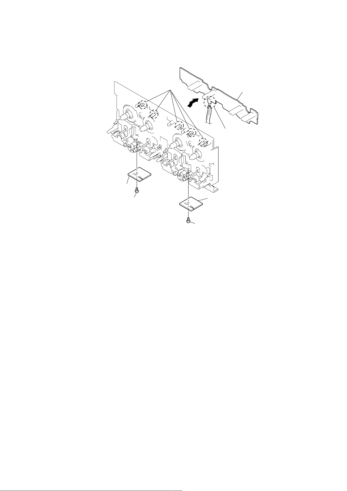
3-12. SW BOARD, HEAD (A) BOARD AND HEAD (B) BOARD
2
five claws
HCD-GX8000/RG77
3
SW board
1
Remove the four solders.
5
head (A) board
4
screw (PTT 2
×
7
4)
6
head (B) board
screw (PTT 2
×
4)
13

HCD-GX8000/RG77
SECTION 4
TEST MODE
[GC TEST MODE]
• This mode is used to check the fluorescent indicator tube, LED,
model, destination software version, volume, key and VACS
level.
Procedure:
1. Press three buttons x , [ENTER], and [DISC 2] simultaneously .
2. LEDs and fluorescent indicator tube are all turned on.
3. When you want to enter the software version display mode,
press [DISC 1]. The model and destination are displayed.
4. Each time [DISC 1] is pressed, the display changes starting
from MC version, GC version, CD version, CDDM version,
CDMA version, CDMB version, BDA version, BDB version,
ST version, T A version, TM version and TC version in this order ,
and returns to the MC version display.
5. When [DISC 3] is pressed while the version numbers are being
displayed except model and destination, year, month and day of
the software creation appear. When [DISC 3] is pressed again, the
display returns to the software version display . When [DISC 1] is
pressed while year, month and day of the software creation are
being displayed, the year, month and day of creation of the software
versions are displayed in the same order of version display .
6. Press [DISC 2] button, and the key check mode is activated.
7. In the key check mode, the fluorescent indicator tube displays
“K0 V0”. Each time a button is pressed, “K” value increases.
However, once a button is pressed, it is no longer taken into
account.
“V” value increases like 1, 2, 3 ... if rotating [VOLUME] knob
in “+” direction, or it decreases like 0, 9, 8 ... if rotating in
“–” direction.
8. Also when [DISC 3] is pressed after lighting of all LEDs and
fluorescent indicator tubes, value of VACS level appears.
9. T o release this mode, press three buttons in the same manner as
step 1, or disconnect the power cord.
[MC TEST MODE]
• This mode is used to check operations of the respective sections
of Amplifier, Tuner , and Tape.
Procedure:
* To enter MC Test Mode
1. Press three buttons of x , [ENTER] and [DISC 3] simultaneously.
2. The messages MUSIC, MOVIE, GAME and P FILE flash on
the fluorescent indicator tube.
The input FUNCTION is changed to VIDEO.
* Tape function
1. When a tape is inserted in tape deck B and recording is started,
the input source function selects VIDEO automatically.
[CD SYNC HI-DUB] button is pressed during recording
When
in function, ALC is turned on.
2. When x button is pressed to stop recording, the tape deck B is
selected and tape is rewound, tape is rew ound using – m button,
tape is stops at around the record-starting position and playback
of the recorded portion of the tape is started. If the [REC PAUSE/
START] button is pressed for a pause and pressed again to resume
recording, when tape deck B is rewound, tape deck B will be
rewound until the position where the pause is applied.
3. When [CD SYNC HI-DUB] button is pressed during playback
of tape deck B, either normal speed or high speed can be selected
by this button.
* AMS Test Mode
1. Select the function “T APE A” or “TAPE B”.
2. Select the loop and relay by pressing the [DIRECTION] button.
Insert a test tape AMS-110A or AMS-120 to selected tape deck.
3. Press the [SPECTRUM] button to enter the AMS test mode.
4. After a tape is rewound first, the FF AMS is checked, and the
mechanism is shut off after detecting the AMS signal twice.
5. Then the REW AMS is checked and the mechanism is shut off
after detecting the AMS signal twice.
6. When the check is complete, a message of either OK or NG
appears.
* To release MC Test mode.
1. To release this mode , press the ?/1 button.
2. The cold reset is enforced at the same time.
[COLD RESET]
• The cold reset clears all data including preset data stored in the
RAM to initial conditions. Execute this mode when returning
the set to the customer.
Procedure:
1. Press three buttons x , [ENTER], and ?/1 simultaneously.
2. The fluorescent indicator tube becomes blank instantaneously,
and the set is reset.
[VACS ON/OFF MODE]
• This mode is used to switch ON and OFF the VACS (Variable
Attenuation Control System).
* Check of Amplifier
1. When v button is pressed, GEQ increases to its maximum and
a message “GEQ MAX” appears.
2. When V button is pressed, GEQ decreases to its minimum and
a message “GEQ MIN” appears.
3. When b or B button is pressed, GEQ is set to flat and a
message “GEQ FLAT” appears.
4. When the [VOLUME] knob is turned clockwise even slightly,
the sound volume increases to its maximum and a message
“VOLUME MAX” appears for two seconds, then the display
returns to the original display.
5. When the [VOLUME] knob is turned counter-clockwise even
slightly, the sound volume decreases to its minimum and a
message “VOLUME MIN” appears for two seconds, then the
display returns to the original display.
* Check of clock frequency
1. T o check the frequency of clock used to run the time in the unit,
the clock output is available at IC501 pin el (CLOCK-OUT)
on the MAIN board only during MC test mode.
2. The frequency is 32.768 kHz or so.
14
Procedure:
1. Press ?/1 button to turn the set ON.
2. Press the [ENTER] and [GAME MIXING] buttons simultaneously .
The message “VACS OFF” or “VACS ON” appears.
[TUNER STEP CHANGE]
• A step of AM channels can be changed over between 9 kHz and
10 kHz.
Procedure:
1. Press ?/1 button to turn the set ON.
2. Select the function “TUNER”, and press [TUNER/BAND]
button to select the BAND “AM”.
3. Press ?/1 button to turn the set OFF.
4. Press [ENTER] and ?/1 buttons simultaneously, and the
display of fluorescent indicator tube changes to “AM 9k STEP”
or “AM 10k STEP”, and thus the channel step is changed over .
HCD-GX8000/RG77
[CD SERVICE MODE]
• This mode can run the CD sled motor freely. Use this mode, for
instance, when cleaning the optical pick-up.
Procedure:
1. Press ?/1 button to turn the set ON.
2. Select the function “CD”.
3. Press three buttons x , [ENTER] , and [OPEN/CLOSE] si-
multaneously.
4. The CD service mode is selected.
5. With the CD in stop status, press M + button to move the
optical pick-up to outside track, or press – m button to inside
track.
6. To release this mode , press the ?/1 button.
[AGING MODE]
This mode can be used for operation check of CD section and tape
deck section.
CD section and tape deck section work in parallel.
• If an error occurred:
The aging operation stops only an error occurred sections and
display then status.
• If no error occurs:
The aging operation continues repeatedly.
Procedure:
1. Press the ?/1 button to turn the power ON, and press the [CD]
button to select the function “CD”.
2. Set discs on all trays, and set tapes into the decks A and B
respectively.
3. Press the [PLAY MODE] b utton to set the “ALL DISCS” mode,
and press the [REPEAT] button to “REPEAT” off.
4. Press three buttons of x , [ENTER], and [EX-CHANGE/DISC
SKIP] simultaneously.
5. Aging operations of CD and tape are started at the same time.
6. To release this mode, press the
power code to turn the power OFF.
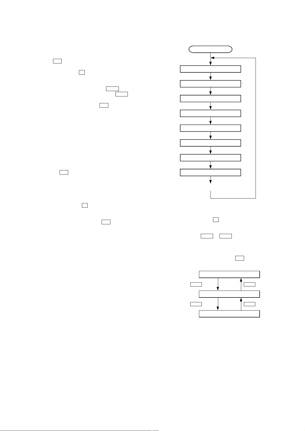
1. Display at the Aging Mode
Display operating state of CD section and tape deck section
alternately.
If an error occurred, stop display which that section.
2. CD Section
The sequence during the aging mode is following as below.
Display at the aging mode is the same as the normal operation.
?/1 button or disconnect the
Aging mode sequence (CD section) :
Start (from disc 1)
Disc chucking
TOC read
Play first track for 2 seconds
Play last track for 2 seconds
EX-change open/close
Open the disc tray
Disc skip
Close the tray
Change the next disc.
• Display at an error occurred (Error display mode)
Procedure:
1. Press three buttons of
x , [ENTER], and [DISC 1] simultaneously
to enter the error display mode.
2. It displays of total error.
3. Each time the – m or M + button is pressed, display change
as below.
4. To clear the error record, operate the cold reset. (Refer to the
“MC COLD RESET”)
5. To release this mode, press the ?/1 button or disconnect the
power plug to turn the power OFF.
Display of total error
– m
Button
M +
Button
Display of Mechanical errors
– m
Button
Display of no disc errors
M +
Button
15
HCD-GX8000/RG77
1) Display of total error
Display
EMC**EDC**
EMC**: The number of mechanical error.
EDC**: The number of no disc error after chucking the disc.
2) Display of mechanical errors
Display
M*$$%%&&##00
M*: The number of mechanical error (“00” is latest one)
(Press the . or > button to changes next error display)
$$: Not used
%%: Loading error (Second figure is not used)
D: The error in the midst of close at the except mechanical
trouble.
E: The error in the midst of open at the except mechanical
trouble.
C: The error in the midst of chucking up at the except
mechanical trouble.
F: The error in the midst of chucking down at the except
mechanical trouble.
&&: Loading error
01: The error in the midst of chucking up.
02: The error in the midst of chucking down.
03: Time-out of EX-open.
05: Time-out of EX-close.
##: Not used
3) Display of no disc errors
Display
D*$$%%&&##00
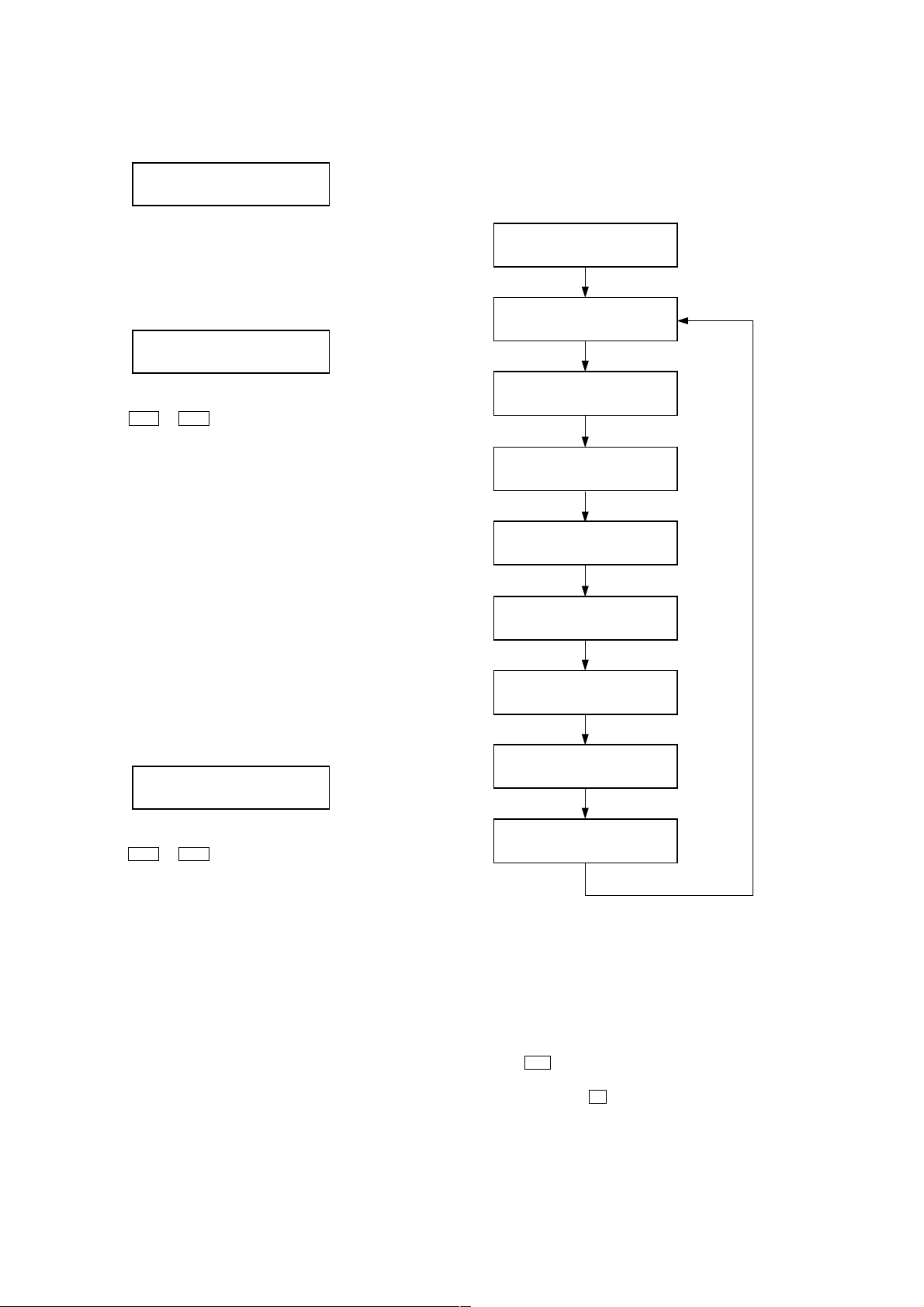
3. Tape Deck Section
The sequence during the aging mode is following as below.
If an error occurred, stop display that step.
Aging mode sequence (Tape deck section) :
Rewind the tape A and B
“TAPE A AG-1”
Shut off
FWD play the tape A
“TAPE A AG-2”
2 minutes
Fast forward the tape A
“TAPE A AG-3”
Shut off or 20 seconds
REV play the tape A
“TAPE A AG-4”
2 minutes
Rewind the tape A
“TAPE A AG-5”
Shut off
FWD play the tape B
“TAPE B AG-2”
2 minutes
Fast forward the tape B
“TAPE B AG-3”
Shut off or 20 seconds
REV play the tape B
“TAPE B AG-4”
2 minutes
D*: The number of mechanical error(“00” is latest one)
(Press the
. or > button to changes next error display)
$$: Error type
01: Focus error
02: GFS error
03: Set up error
%%: Not used
&&:
00: No disc judgment without chucking retry.
01: No disc judgment after chucking retry.
##: The state when judged no disc error
01: Stop
02: Set up
03: TOC read
04: Access
05: Play
06: Pause
07: Manual search (Play)
08: Manual search (Pause)
16
Rewind the tape B
“TAPE B AG-5”
Shut off
Note: “TAPE * AG-*” is display of each step.
[CD REPEAT 5 LIMIT OFF MODE]
Number of repeat for CD playback is 5 times when the repeat mode
is “REPEA T”. This mode enables CD to repeat playback for limitless
times.
Procedure:
1. Press the ?/1 button to turn the power on, and press the [CD]
button to select the function “CD”.
2. Press three buttons of x , [REPEAT], and [CD] simultaneously
to enter the CD repeat 5 limit off mode and display “REPEAT
OFF”.
3. To release this mode, operate the cold reset. (Refer to the “MC
COLD RESET”)

[CD SHIP MODE (MEMORY CLEAR) ]
• This mode moves the optical pick-up to the position durable to
vibration. Use this mode when returning the set to the customer
after repair.
Procedure:
1. Set to the standby state.
2. Press three buttons x , [ENTER] and [GAME] simultaneously .
3. After the “STANDBY” display blinks, a message “LOCK” is
displayed on the fluorescent indicator tube, and the CD ship
mode is set.
[CD SHIP MODE (NO MEMORY CLEAR) ]
• This mode moves the optical pick-up to the position durable to
vibration. Use this mode when returning the set to the customer
after repair.
Procedure:
1. Set to the standby state.
2. Press the [CD] and ?/1 buttons simultaneously.
3. After the “STANDBY” display blinks, a message “LOCK” is
displayed on the fluorescent indicator tube, and the CD ship
mode is set.
HCD-GX8000/RG77
17
HCD-GX8000/RG77
SECTION 5
MECHANICAL ADJUSTMENTS
SECTION 6
ELECTRICAL ADJUSTMENTS
Precaution
1. Clean the following parts with a denatured alcohol-moistened
swab:
record/playback heads pinch rollers
erase head rubber belts
capstan idlers
2. Demagnetize the record/playback head with a head
demagnetizer.
3. Do not use a magnetized screwdriver for the adjustments.
4. After the adjustments, apply suitable locking compound to the
parts adjusted.
5. The adjustments should be performed with the rated power
supply voltage unless otherwise noted.
Torque Measurement
Mode Torque meter
FWD
FWD
back tension
REV
REV
back tension
FF/REW
FWD tension
REV tension
CQ-102C
CQ-102C
CQ-102RC
CQ-102RC
CQ-201B
CQ-403A
CQ-403R
Meter reading
3.06 N • m to 6.96 N • m
31 to 71 g • cm
(0.43 – 0.98 oz • inch)
0.19 N • m to 0.58 N • m
2 to 6 g • cm
(0.02 – 0.08 oz • inch)
3.06 N • m to 6.96 N • m
31 to 71 g • cm
(0.43 – 0.98 oz • inch)
0.19 N • m to 0.58 N • m
2 to 6 g • cm
(0.02 – 0.08 oz • inch)
6.96 N • m to 14.02 N • m
71 to 143 g • cm
(0.98 – 1.99 oz • inch)
9.80 N • m
100 g or more
(3.53 oz or more)
9.80 N • m
100 g or more
(3.53 oz or more)
DECK SECTION
1. Demagnetize the record/playback head with a head
demagnetizer.
2. Do not use a magnetized screwdriver for the adjustments.
3. After the adjustments, apply suitable locking compound to the
parts adjust.
4. The adjustments should be performed with the rated power
supply voltage unless otherwise noted.
5. The adjustments should be performed in the order given in this
service manual. (As a general rule, playback circuit adjustment
should be completed before performing recording circuit
adjustment.)
6. The adjustments should be performed for both L-CH and RCH.
7. Switches and controls should be set as follows unless otherwise
specified.
• Test Tape
Tape Signal Used for
P-4-A100 10 kHz, –10 dB Azimuth Adjustment
WS-48B 3 kHz, 0 dB Tape Speed Adjustment
0 dB=0.775 V
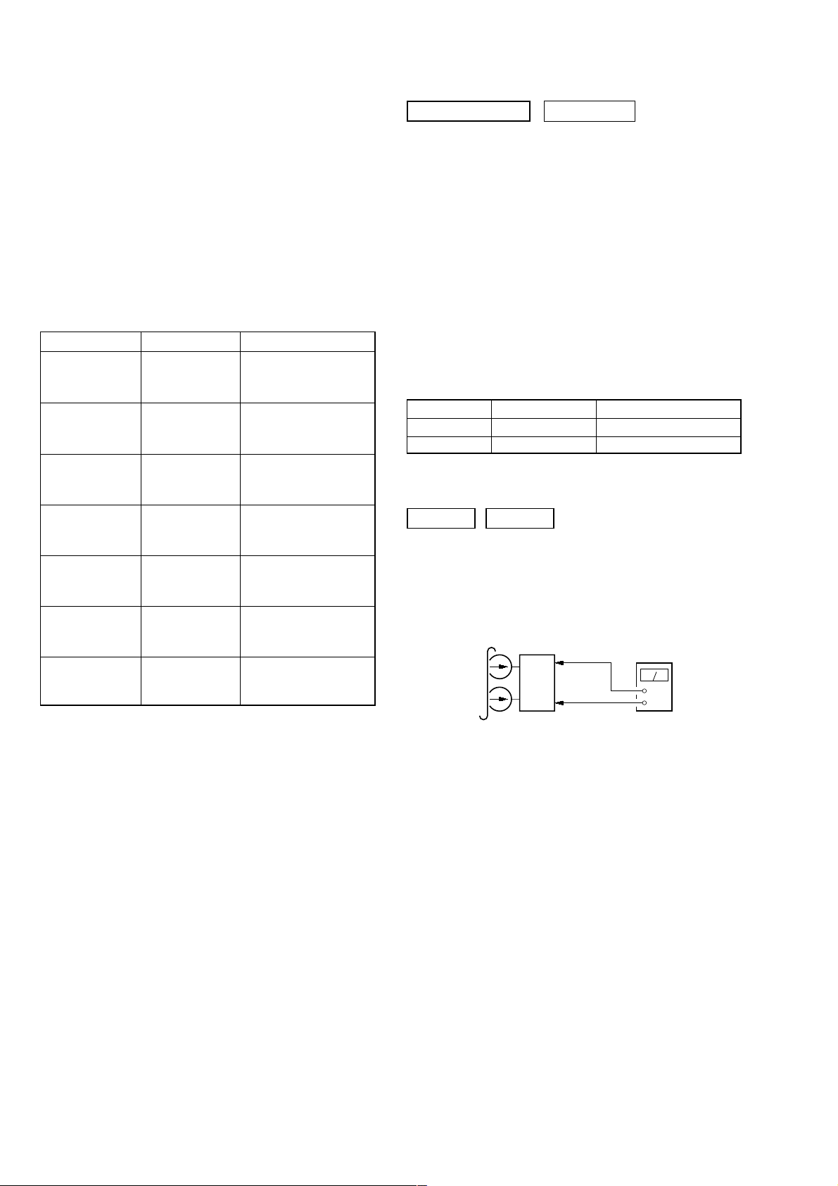
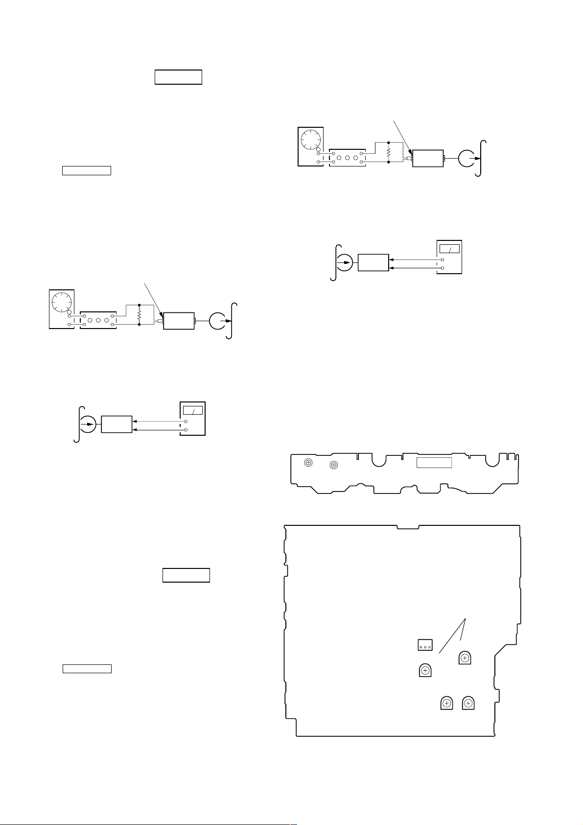
RECORD/PLA YBA CK HEAD AZIMUTH ADJUSTMENT
DECK A DECK B
Note: Perform this adjustments for both decks
Procedure:
1. Mode: Playback
test tape
P-4-A100
(10 kHz, –10 dB)
set
MAIN board
CN301
Pin
1
(L-CH)
3
(R-CH)
Pin
MAIN board
CN301
2
(GND)
Pin
level meter
+
–
18
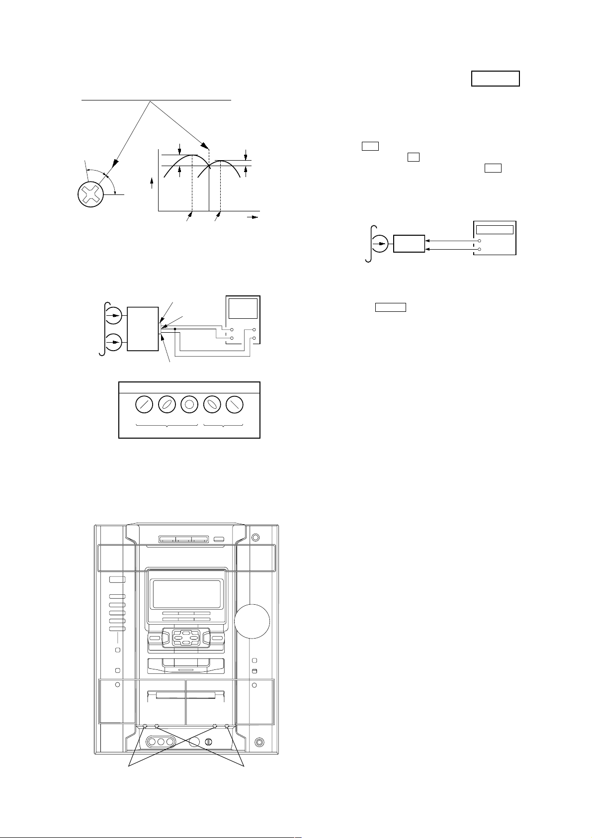
HCD-GX8000/RG77
e
2. Turn the adjustment screw and check output peaks. If the peaks
do not match for L-CH and R-CH, turn the adjustment screw
so that outputs match within 1dB of peak.
Output
level
within
1dB
L-CH
peak
R-CH
peak
within
1dB
Screw
position
L-CH
peak
Screw
position
R-CH
peak
3. Mode: Playback
test tape
P-4-A100
(10 kHz, –10 dB)
L-CH
MAIN
board
CN301
set
R-CH
waveform of oscilloscope
in phase 45°90°135°180
pin
L
R
pin
good
1
pin
3
2
oscilloscop
V
wrong
H
°
TAPE SPEED ADJUSTMENT DECK B
Note: Start the Tape Speed adjustment as below after setting to the test
mode.
In the test mode, the tape speed is high during pressing the
[CD SYNC HI-DUB] button.
Procedure:
1. Press ?/1 button to turn the set ON.
2. Press three buttons x , [ENTER] and [DISC 3] simultaneously .
To release from the test mode, press the ?/1 button.
Mode: Playback
test tape
WS-48B
(3 kHz, 0 dB)
1. Insert the WS-48B into the deck B.
2. Press the hH button on the deck B.
3. Press the [CD SYNC HI-DUB] button in playback mode.
Then at HIGH speed mode.
4. Adjust RV1001 on the SW board so that frequency counter r eads
6,000 ± 180 Hz.
5. Press the [CD SYNC HI-DUB] button.
Then back to NORMAL speed mode.
6. Adjust RV1002 on the SW board so that frequency counter r eads
3,000 ± 90 Hz.
Adjustment Location: SW board
Sample Value of Wow and Flutter: 0.3% or less W. RMS (JIS)
MAIN board
CN301
Pin
Pin
set
MAIN board
CN301 Pin
1
(L-CH)
3
(R-CH)
frequency counter
+
–
2
(GND)
(WS-48B)
4. After the adjustments, apply suitable locking compound to the
pats adjusted.
Adjustment Location: Playback Head (Deck A).
Record/Playback/Erase Head (Deck B).
forward
reverse
19
HCD-GX8000/RG77
REC BIAS ADJUSTMENT DECK B
Procedure:
In the MC test mode, the “REC memory mode” is convenient for
this adjustment. In the “REC memory mode” , when the REC starts
the input signal FUNCTION is switched to VIDEO automatically.
When the REC stops, the tape returns near to the recording start
position.
1. Press MD (VIDEO) button to select VIDEO. (This step is not
necessary if the above test mode has already been set)
2. Insert a tape into deck B.
3. After press [REC PAUSE/START] button, press [REC PAUSE/
START] button, then recording start.
4. Mode: Record
MAIN board
MD/VIDEO (AUDIO) IN (J750)
1) 315 Hz
2) 10 kHz
AF OSC
attenuator
5. Mode: Playback
recorded
portion
600
MAIN board
CN301
1
Pin
3
Pin
set
MAIN board
CN301 Pin
50 mV (–23.8 dB)
Ω
set
2
(GND)
level meter
+
–
(L-CH)
(R-CH)
blank tape
CN-123
4. Mode: Record
MAIN board
MD/VIDEO (AUDIO) IN (J750)
AF OSC
315 Hz, 50 mV (–23.8 dB)
Ω
attenuator
600
blank tape
CS-123
set
5. Mode: Playback
MAIN board
recorded
portion
CN301
1
Pin
3
Pin
set
MAIN board
CN301 Pin
(L-CH)
(R-CH)
2
level meter
+
–
(GND)
6. Confirm the play back signal recorded in step 3 becomes
adjustable level as follows.
If these levels are not adjustable level, adjust the RV301 (LCH) and RV351 (R-CH) on the MAIN board to repeat steps 4
and 5.
Adjustable level:
CN301 PB level: 47.2 to 53.0 mV (–24.3 to –23.3 dB)
Adjustment Location: MAIN board
– SW BOARD (Component Side) –
TAPE SPEED
ADJUSTMENT
(NORMAL) (HIGH)
6. Confirm the playback signal recorded in step 3 becomes
adjustable level as follows.
If these levels are not adjustable level, adjust the RV304 (LCH) and R V354 (R-CH) on the MAIN board to repeat steps 4
and 5.
Adjustable level: Playback output of 315 Hz to playback output
of 10 kHz: ±1.0 dB
Adjustment Location: MAIN board
REC LEVEL ADJUSTMENT DECK B
Procedure:
In the MC test mode, the “REC memory mode” is convenient for
this adjustment. In the “REC memory mode” , when the REC starts
the input signal FUNCTION is switched to VIDEO automatically.
When the REC stops, the tape returns near to the recording start
position.
1. Press MD (VIDEO) button to select VIDEO. (This step is not
necessary if the above test mode has already been set)
2. Insert a tape into deck B.
3. After press [REC PAUSE/START] button, press [REC PAUSE/
START] button, then recording start.
RV1002
– MAIN BOARD (Component Side) –
RV1001
REC BIAS ADJUSTMENT
CN1001
REC LEVEL
ADJUSTMENT
CN301
31
(R-CH)
RV351
RV304 RV354
(L-CH)
(L-CH)
RV301
(R-CH)
20
HCD-GX8000/RG77
p
e
)
CD SECTION
Note:
1. CD Block is basically designed to operate without adjustment. Therefore,
check each item in order given.
2. Use LUV-P01 (4-999-032-01) unless otherwise indicated.
3. Use an oscilloscope with more than 10MΩ impedance.
4. Clean the object lens by an applicator with neutral detergent when the
signal level is low than specified value with the following checks.
S-CURVE CHECK
Oscilloscope
BD board
TP(FEO)
TP(DVC)
Procedure :
1. Connect an oscilloscope to TP (FEO).
2. Connect between TP (FEI) and TP (DVC) ( 1.65 V) by lead
wire.
3. Turn the power ON.
4. Load a disc (LUV-P01) and actuate the focus search. (In
consequence of open and close the disc tray, actuate the focus
search)
5. Confirm that the oscilloscope waveform (S-curve) is
symmetrical between A and B. And confirm peak to peak level
within 2 ± 0.5 Vp-p.
S-curve waveform
symmetry
A
±
within 2
B
0.5Vp-
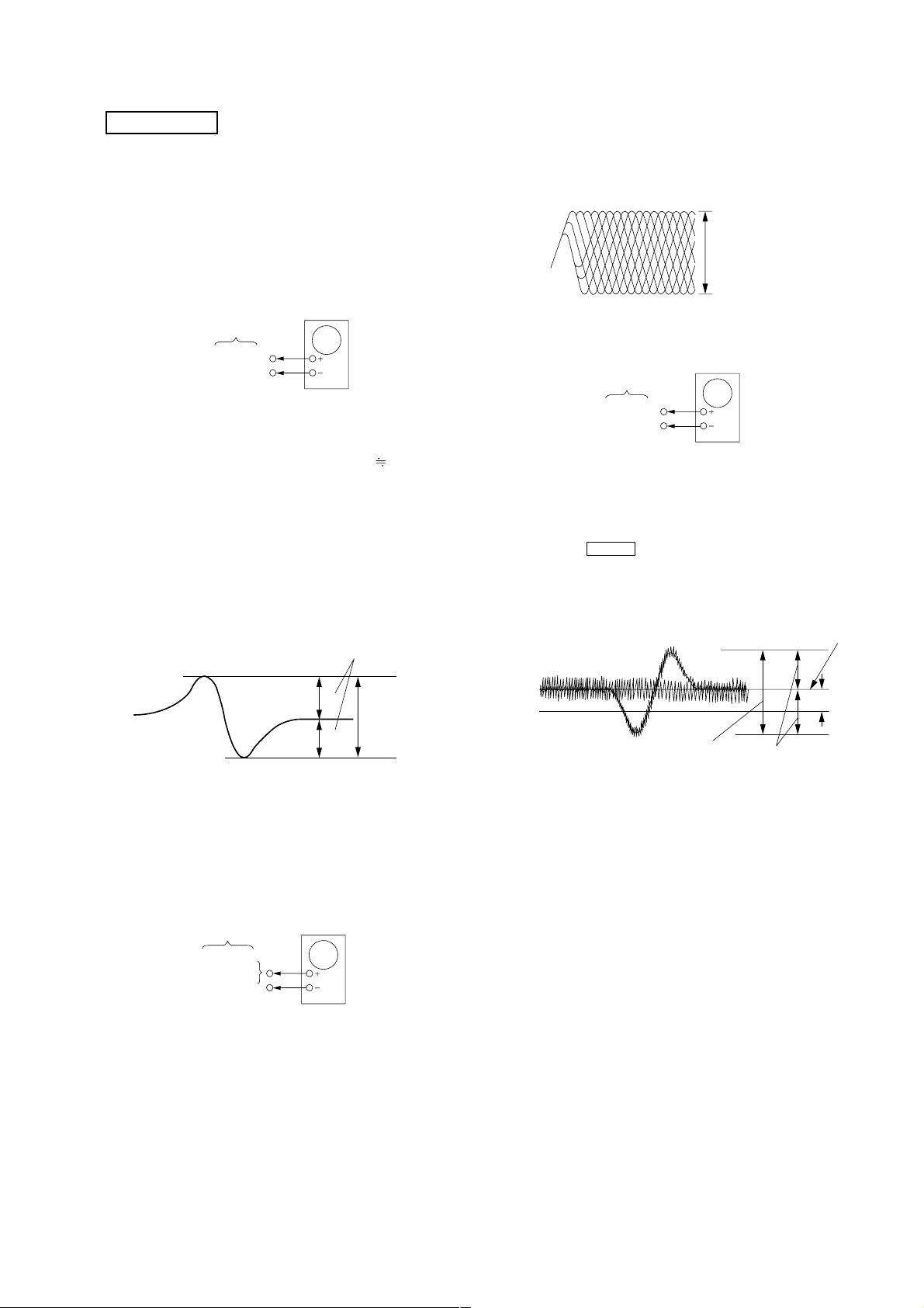
Note: Clear RF signal waveform means that the shape “ ◊ ” can be clearly
distinguished at the center of the waveform.
RF signal waveform
VOLT/DIV : 200mV
TIME/DIV : 500ns
±
level : 0.65
0.15Vp-p (RFDC)
1.1
±
0.4Vp-p (RFAC)
E-F BALANCE (1 TRACK JUMP) ADJUSTMENT
oscilloscop
BD board
TP(TEO)
TP(DVC)
Procedure :
1. Connect an oscilloscope to TP (TEO) and TP (DVC).
2. Turn the power ON.
3. Load a disc (LUV-P01) and playback the number nine track.
4. Press the hH button. (Becomes the 1 track jump mode.)
5. Confirm that the level B and A (DC voltage) on the oscilloscope
waveform.
1 track jump waveform
DVC
level=1.0 ±0.5Vp-p
B
symmetry
center of
waveform
A (DC voltage
6. After check, remove the lead wire connected in step 2.
Note: • Try to measure several times to make sure than the ratio
of A : B or B : A is more than 10 : 7.
• Take sweep time as long as possible and light up the
brightness to obtain best waveform.
RF LEVEL CHECK
BD board
TP(RFDC)
TP(RFAC)
TP(DVC)
Procedure :
1. Connect an oscilloscope CH1 to TP (RFDC) and CH2 to TP
(RFAC).
2. Turn the power ON.
3. Load a disc (LUV-P01) and playback.
4. Confirm that oscilloscope waveform is clear and check if RF
signal level is correct or not.
oscilloscope
6. Adjust RV101 on the BD board so tha t the center of waveform
becomes the same voltage of DVC. (i.e. A=0V)
Connecting and Adjustment Location: BD board
21

HCD-GX8000/RG77
Connecting and Adjustment Location:
– BD BOARD (Component Side) –
TP
TP
(DVC)
(FEO)
TP
(RFAC)
TP
(FEI)
TP
(RFDC)
TP
(TEO)
– BD BOARD (Conductor Side) –
RV101
E-F BALANCE
(1 TRACK JUMP)
ADJUSTMENT
22
 Loading...