

Sony HCDRG-55-S Service manual
HCD-RG55/RG55S
SERVICE MANUAL
Ver 1.1 2002. 06
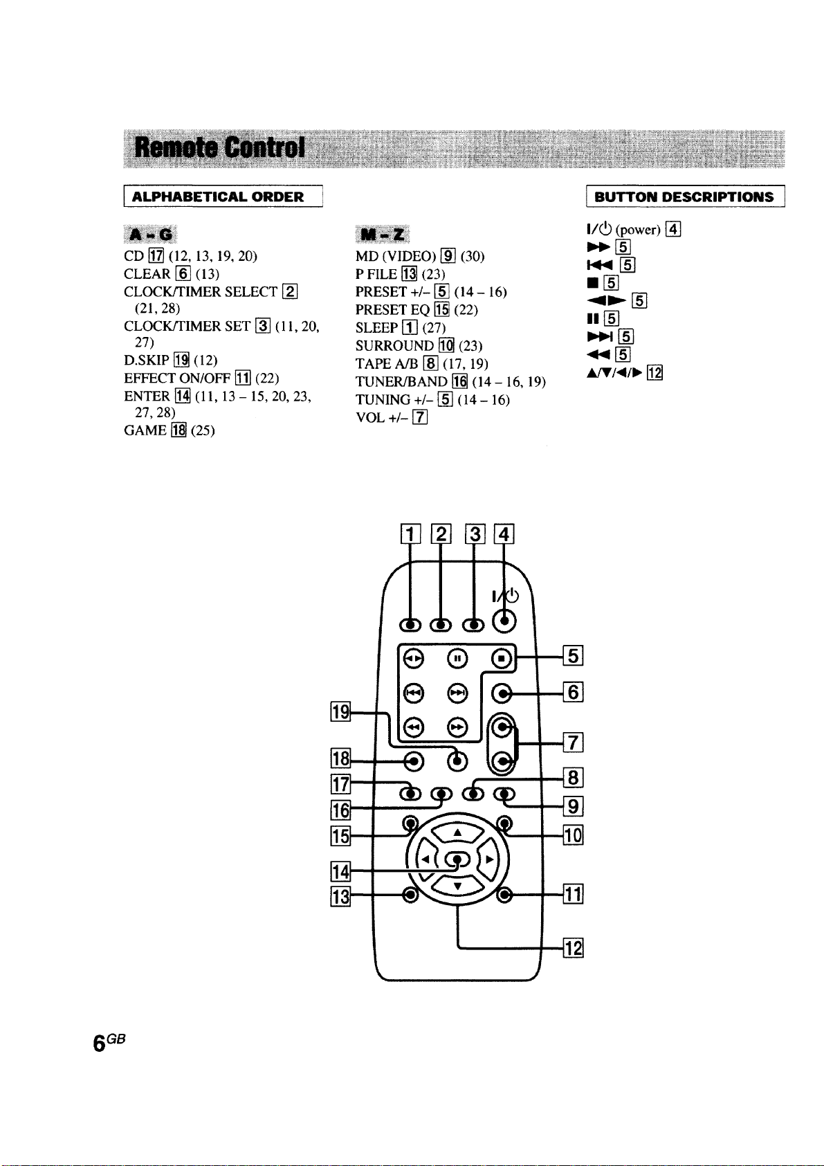
• HCD-RG55/RG55S is the tuner,
deck, CD and amplifier section in
MHC-RG55/RG55S.
CD
section CDM58FS-K6A
Tape deck
Section Tape Transport Mechanism Type
AEP Model
UK Model
HCD-RG55S
E Model
Australian Model
HCD-RG55
Model Name Using Similar Mechanism NEW
CD Mechanism Type
Optical Pick-up Name KSM-213DCP
Model Name Using Similar Machanism NEW
CDM58F-K6A
RG55: CWL43RR51
RG55S: CWL43FR50
Amplifier section
European model:
HCD-RG55S
Front speaker
DIN power output (rated)
50+50 watts (6 ohms at
1 kHz, DIN)
Continuous RMS power output (reference)
60+60 watts (6 ohms at
1 kHz, 10% THD)
Music power output (reference)
120+120 watts (6 ohms
at 1 kHz, 10% THD)
Sub woofer
DIN power output (rated)
100 watts (12 ohms at
40 Hz, DIN)
Continuous RMS power output (reference)
120 watts (12 ohms at
40 Hz, 10% THD)
Music power output (reference)
120 watts (12 ohms at
40 Hz, 10% THD)
Other models:
HCD-RG55
The following measured at AC 120, 220, 230 –
240 V, 50/60 Hz
DIN power output (rated)
100+100 watts (6 ohms
at 1 kHz, DIN)
SPECIFICATIONS
Continuous RMS power output (reference)
120+120 watts (6 ohms
at 1 kHz, 10% THD)
Inputs
MD/VIDEO (AUDIO) IN (phono jacks):
voltage 450/250 mV,
impedance 47 kilohms
GAME (AUDIO) IN (phono jack):
voltage 450 mV,
impedance 47 kilohms
MIC (phone jack) (except for European models):
sensitivity 1 mV,
impedance 10 kilohms
Outputs
PHONES (stereo mini jack):
accepts headphones of
8 ohms or more
Front speaker: accepts impedance of 6 to
16 ohms
Sub woofer speaker (MHC-RG55S only):
accepts impedance of 12
to 16 ohms
– Continued on next page –
COMPACT DISC DECK RECEIVER
9-874-003-02
2002F0400-1
© 2002. 06
Sony Corporation
Home Audio Company
Published by Sony Engineering Corporation
1

HCD-RG55/RG55S
CD player section
System Compact disc and digital
audio system
Laser Semiconductor laser
(λ=780 nm)
Emission duration:
continuous
Frequency response 2 Hz – 20 kHz (±0.5 dB)
Wavelength 780 – 790 nm
Signal-to-noise ratio More than 90 dB
Dynamic range More than 90 dB
CD OPTICAL DIGITAL OUT
(Square optical connector jack, rear panel)
Wavelength 660 nm
Output Level –18 dBm
Tape deck section
Recording system 4-track 2-channel stereo
Frequency response 50 – 13,000 Hz (±3 dB),
using Sony TYPE I
cassette
Wow and flutter ±0.15% W.Peak (IEC)
0.1% W.RMS (NAB)
±0.2% W.Peak (DIN)
Tuner section
FM stereo, FM/AM superheterodyne tuner
FM tuner section
Tuning range 87.5 – 108.0 MHz
Antenna FM lead antenna
Antenna terminals 75 ohm unbalanced
Intermediate frequency 10.7 MHz
AM tuner section
Tuning range
European and Middle Eastern models:
531 – 1,602 kHz (with the
interval set at 9 kHz)
Other models: 531 – 1,602 kHz (with the
interval set at 9 kHz)
530 – 1,710 kHz (with the
interval set at 10 kHz)
Antenna AM loop antenna
Antenna terminals External antenna terminal
Intermediate frequency 450 kHz
General
Power requirements
European model: 230 V AC, 50/60 Hz
Australian models: 230 – 240 V AC, 50/60 Hz
Mexican model: 120 V AC, 50/60 Hz
Argentine models: 220 V AC, 50/60 Hz
Korean model: 220 V AC, 60 Hz
Other models: 120 V, 220 V or 230 –
240 V AC, 50/60 Hz
Adjustable with voltage
selector
Power consumption
European models:
HCD-RG55S: 150 watts
0.5 watts (at the Power
Saving Mode)
Other models:
HCD-RG55: 200 watts
Dimensions (w/h/d) Approx. 280 × 325 × 421 mm
Mass
HCD-RG55S: Approx. 9.0 kg
HCD-RG55: Approx. 10.0 kg
Supplied accessories: AM loop antenna (1)
Remote Commander (1)
Batteries (2)
FM lead antenna (1)
Front speaker pads (8)
Design and specifications are subject to change without
notice.
CAUTION
Use of controls or adjustments or performance of procedures
other than those specified herein may result in hazardous
radiation exposure.
Notes on Chip Component Replacement
• Never reuse a disconnected chip component.
• Notice that the minus side of a tantalum capacitor may be
damaged by heat.
Flexible Circuit Board Repairing
• Keep the temperature of soldering iron around 270°C during
repairing.
• Do not touch the soldering iron on the same conductor of the
circuit board (within 3 times).
• Be careful not to apply force on the conductor when soldering
or unsoldering.
SAFETY-RELATED COMPONENT WARNING!!
COMPONENTS IDENTIFIED BY MARK 0 OR DOTTED LINE
WITH MARK 0 ON THE SCHEMATIC DIAGRAMS AND IN
THE PARTS LIST ARE CRITICAL TO SAFE OPERATION.
REPLACE THESE COMPONENTS WITH SONY P ARTS WHOSE
PART NUMBERS APPEAR AS SHOWN IN THIS MANUAL OR
IN SUPPLEMENTS PUBLISHED BY SONY.
2
HCD-RG55/RG55S
NOTES ON HANDLING THE OPTICAL PICK-UP BLOCK
OR BASE UNIT
The laser diode in the optical pick-up block may suffer electrostatic
breakdown because of the potential difference generated by the
charged electrostatic load, etc. on clothing and the human body.
During repair, pay attention to electrostatic break-down and also
use the procedure in the printed matter which is included in the
repair parts.
The flexible board is easily damaged and should be handled with
care.
NOTES ON LASER DIODE EMISSION CHECK
The laser beam on this model is concentrated so as to be focused on
the disc reflective surface by the objective lens in the optical pickup block. Therefore, when checking the laser diode emission,
observe from more than 30 cm away from the objective lens.
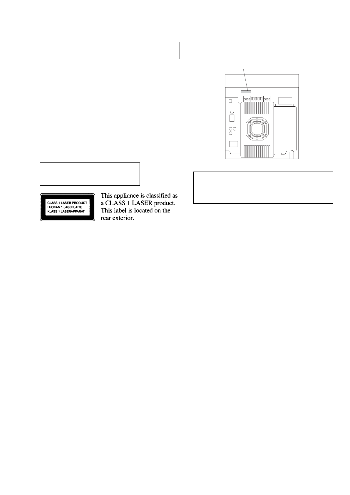
Laser component in this product is capable
of emitting radiation exceeding the limit for
Class 1.
SETTING AND RELEASING THE CD DISC TRAY LOCK
FUNCTION
This set has a disc tray lock function to prevent discs for
demonstration at shops from theft. While this lock function is set,
the tray will not be delivered out even when the OPEN/CLOSE
button is pressed.
MODEL IDENTIFICATION
– BACK PANEL –
PARTS No.
MODEL PARTS No.
AR, E2, E51, SP models 4-238-649-01
AUS, KR, MX models 4-238-649-21
AEP, UK models 4-238-649-31
• Abbreviation
AUS : Australian model AR : Argentina model
SP : Singapore model E2 : Central and South America model
KR : Korea model E51 : Chilean and Peruvian model
MX : Mexican model
Setting method:
Press the OPEN/CLOSE button while pressing the STOP button.
After a few seconds, the message “LOCKED” will appear on the
fluorescent indicator tube with the tray locked.
Releasing method:
Just as the lock is set, press the OPEN/CLOSE button while
pressing the STOP button.
After a few seconds, the message “UNLOCKED” will appear with
the lock released.
3

HCD-RG55/RG55S
TABLE OF CONTENTS
1. SERVICE NOTE ................................................................ 5
2. GENERAL
Main Unit ................................................................................ 6
Remote Control ....................................................................... 7
3. DISASSEMBLY
3-1. Case (Top) ........................................................................... 9
3-2. CD (Door) ........................................................................... 9
3-3. Front Panel Section (AEP, UK Model) ............................. 10
3-4. Front Panel Section (Except AEP, UK Model) ................. 11
3-5. Tape Mechanism Deck ...................................................... 12
3-6. Panel Board (AEP, UK Model) ......................................... 12
3-7. Panel Board (Except AEP, UK Model) ............................. 13
3-8. Key Board ......................................................................... 13
3-9. Sensor Board, DC Fan (FAN961) ..................................... 14
3-10. Main Board, Sub Woofer Board, P ower Board ................. 15
3-11. CD Board .......................................................................... 15
3-12. Base Unit ...........................................................................16
3-13. Driver Board, Motor Board, Sensor (CD) Board ..............16
4. TEST MODE ..................................................................... 17
5. ELECTRICAL ADJUSTMENTS................................. 21
6. DIAGRAMS
6-1. Circuit Boards Location .................................................... 23
6-2. Printed Wiring Boards –CD Section (1/2)– ...................... 25
6-3. Printed Wiring Boards –CD Section (2/2)– ...................... 26
6-4. Schematic Diagram –CD Section–.................................... 27
6-5. Printed Wiring Board –Main Section– .............................. 28
6-6. Schematic Diagram –Main Section (1/4)– ........................30
6-7. Schematic Diagram –Main Section (2/4)– ........................31
6-8. Schematic Diagram –Main Section (3/4)– ........................32
6-9. Schematic Diagram –Main Section (4/4)– ........................33
6-10. Printed Wiring Boards –Panel Section– ............................ 34
6-11. Schematic Diagram –Panel Section– ................................ 35
6-12. Printed Wiring Board –Key Section– ................................36
6-13. Schematic Diagram –Key Section–................................... 37
6-14. Printed Wiring Board –Sub Woofer Section– ................... 38
6-15. Schematic Diagram –Sub Woofer Section– ...................... 39
6-16. Printed Wiring Boards –Power Section (1/3)– ..................40
6-17. Printed Wiring Board –Power Section (2/3)– ................... 41
6-18. Printed Wiring Board –Power Section (3/3)– ................... 42
6-19. Schematic Diagram –Power Section– ...............................43
7. EXPLODED VIEWS
7-1. Main Section ..................................................................... 46
7-2. Front panel Section ........................................................... 47
7-3. Main Board Section .......................................................... 48
7-4. CD Mechanism Deck Section ........................................... 49
7-5. Optical Pick-up Section..................................................... 50
8. ELECTRICAL PARTS LIST ........................................ 51
4
SECTION 1
d
SERVICE NOTE
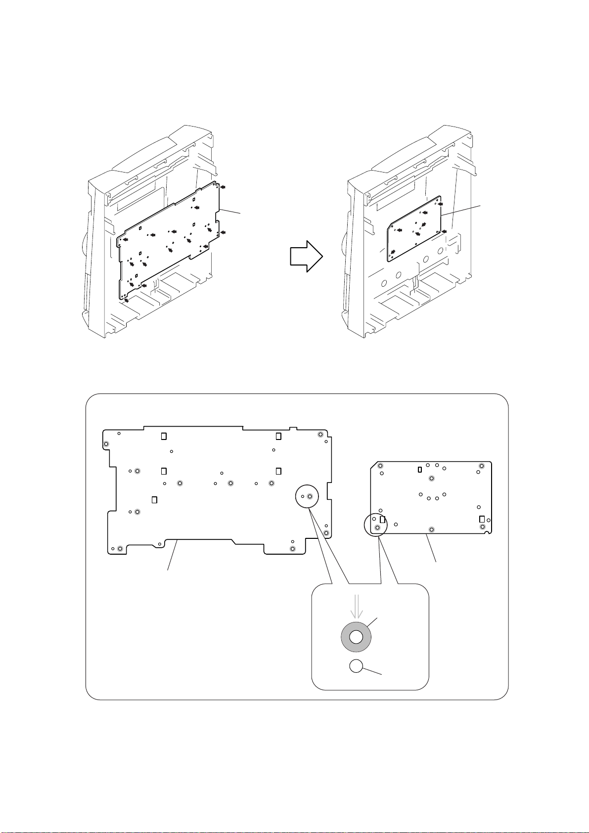
REMOVING THE PANEL BOARD AND THE KEY BOARD
* The panel board and the key board only are connected to the front panel
by means of hot-melting the plastics.
2
PANEL board
HCD-RG55/RG55S
4
KEY boar
1
Cut the fifteen melted-connection points
with a cutting plier.
Note for installing the panel board and the key board
PANEL board
(eleven screw holes)
3
Cut the seven melted-connection points
with a cutting plier.
KEY board
(six screw holes)
Screw hole
In order to re-install the panel board and the key board,
fix them by using the screws (+BVTP 2.6
Screw in to the respective screw holes.
Do not tighten the screws excessively.
×
8 ) respectively.
Hot melt
5
HCD-RG55/RG55S
SECTION 2
GENERAL
This section is extracted
from instruction manual.
6
HCD-RG55/RG55S
7
HCD-RG55/RG55S
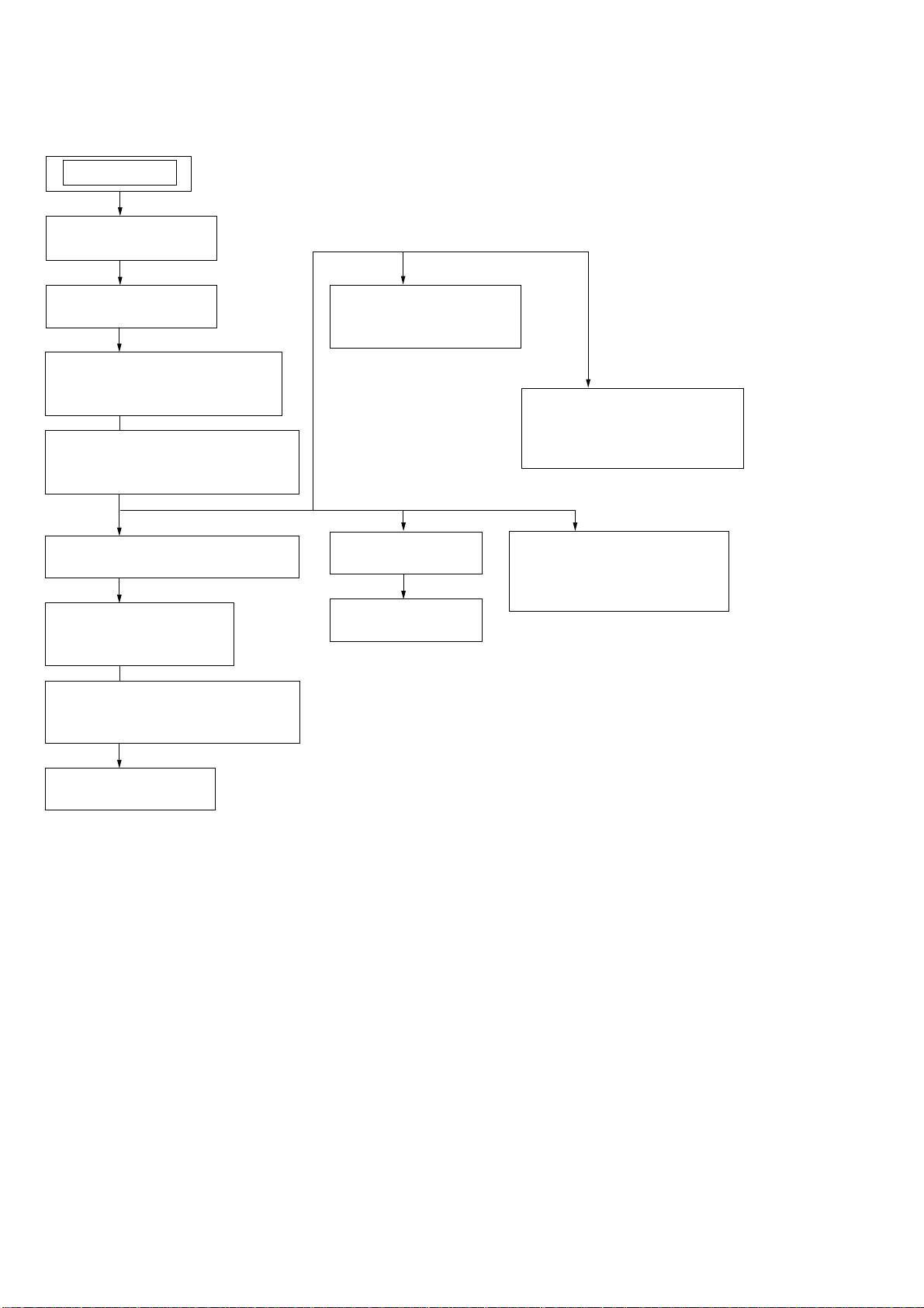
Note : Disassemble the unit in the order as shown below.
SET
3-1. CASE (TOP)
(Page 9)
SECTION 3
DISASSEMBLY
3-2. CD (DOOR)
(Page 9)
3-3. FRONT PANEL SECTION
(AEP, UK MODEL)
(Page 10)
3-4. FRONT PANEL SECTION
(EXCEPT AEP, UK MODEL)
(Page 11)
3-5. TAPE MECHANISM DECK
(Page 12)
3-6. PANEL BOARD
(AEP, UK MODEL)
(Page 12)
3-7. PANEL BOARD
(EXCEPT AEP, UK MODEL)
(Page 13)
3-9. SENSOR BOARD
DC FAN (FAN961)
(Page 14)
3-11. CD BOARD
(Page 15)
3-12 BASE UNIT
(Page 16)
3-10. MAIN BOARD,
SUB WOOFER BOARD ,
POWER BOARD
(Page 15)
3-13. DRIVE BOARD,
MOTOR (TC) BOARD,
SENSOR (TC) BOARD
(Page 16)
3-8. KEY BOARD
(Page 13)
8
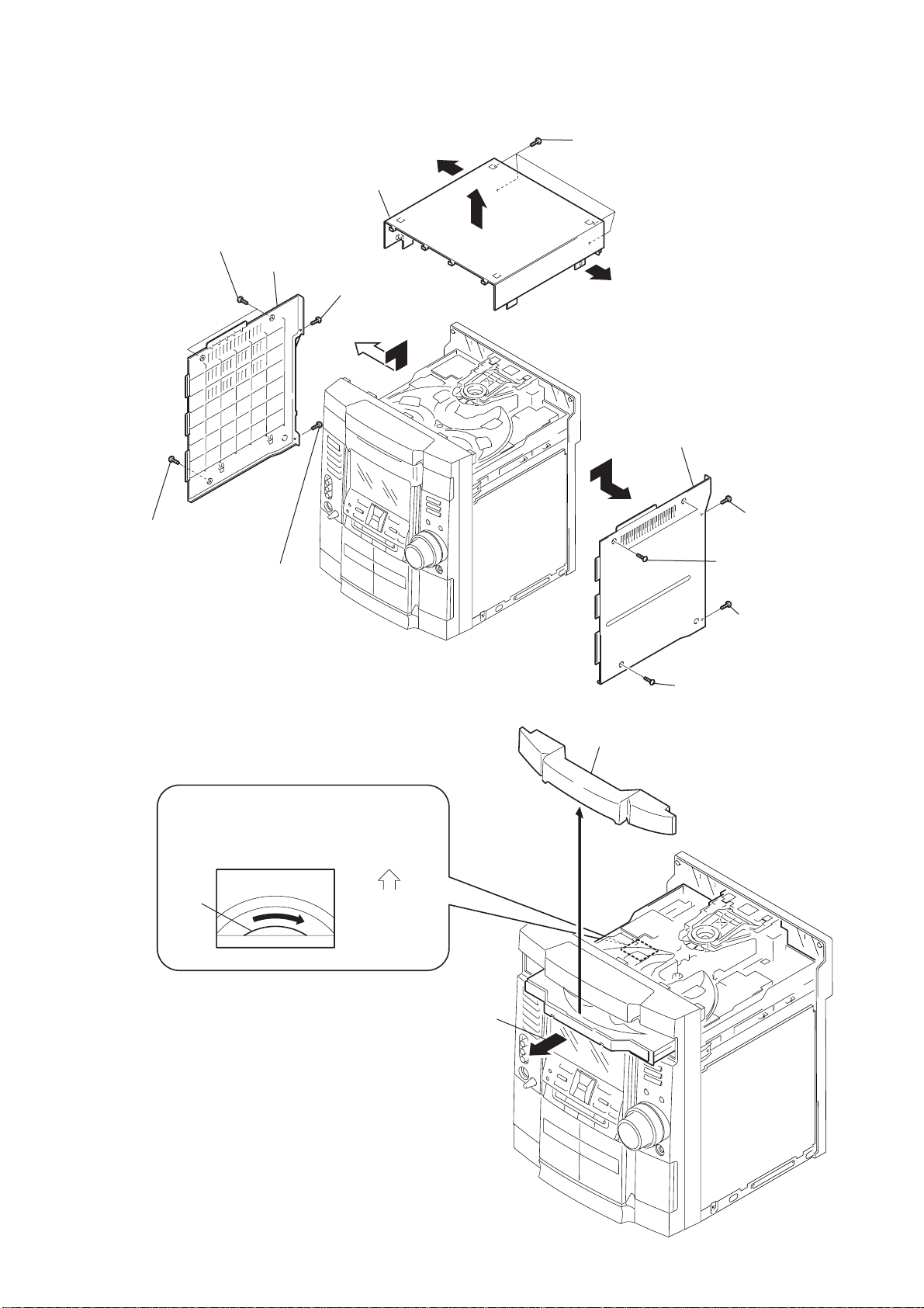
3-1. CASE (TOP)
6
two screws (case 3 TP2)
case (side-L)
case (top)
8
screw
(+BVTP 3
×
q;
qs
10)
qd
qa
four screws (+BVTP 3
qs
5
HCD-RG55/RG55S
×
10)
case (side-R)
7
screw (case 3 TP2)
3-2. CD (DOOR)
CD mechanism deck (CDM58F)
1
Turn the pulley to the direction of arrow.
pulley
9
screw
(+BVTT 3
×
8)
Front panel side
CD door
3
3
(+BVTP 3
1
two screws
(case 3 TP2)
4
(+BVTT 3
2
screw (case 3 TP2)
screw
screw
×
×
10)
8)
2
Pull-out the disc tray.
9
HCD-RG55/RG55S
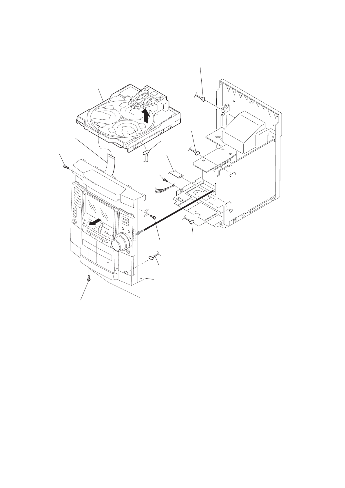
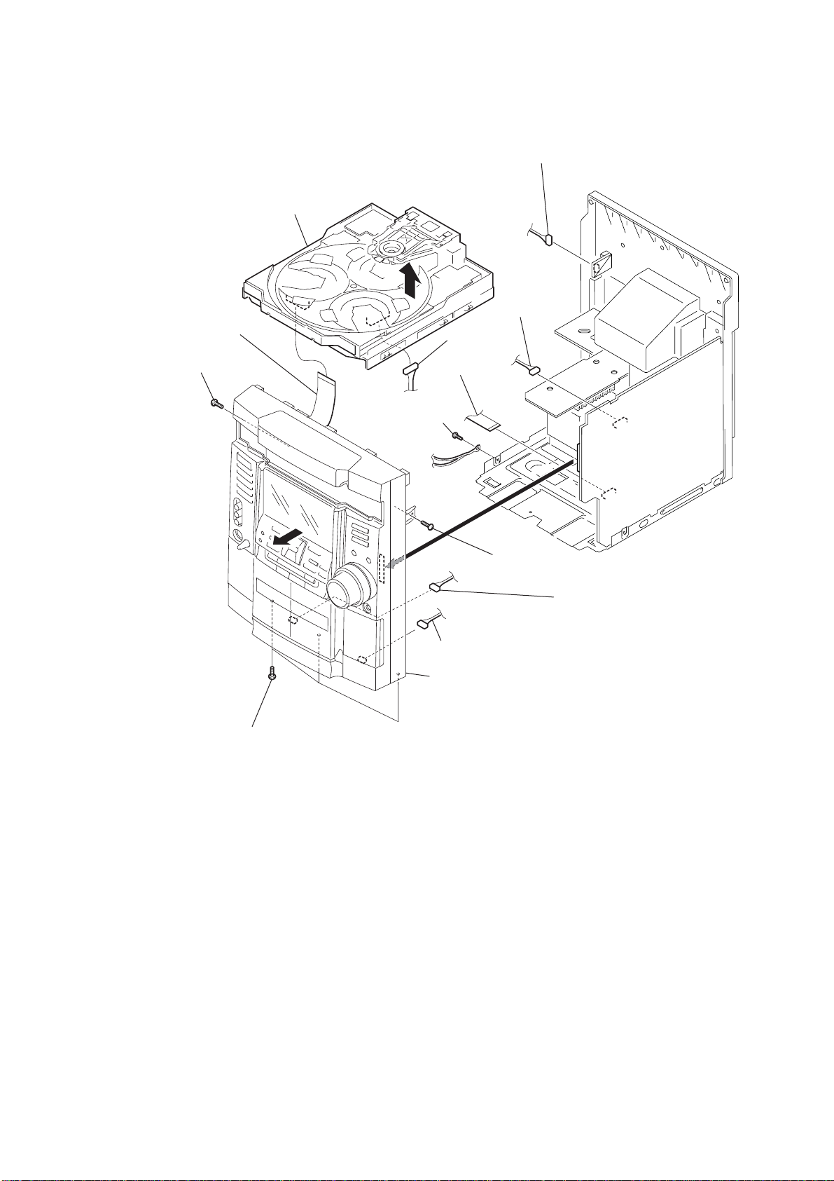
3-3. FRONT PANEL SECTION (AEP, UK MODEL)
CD mechanism deck (CDM58F)
qd
2
CN733 (flat type)
9
screw
(+BVTP 3
×
10)
7
screw
(+BVTP 3
1
CN605
4
CN305
qf
CN302
(flat type)
3
CN302
(flat type)
×
10)
qa
0
three screws (+BVTP 3
qs
× 6
front panel section
)
8
screw
(+BVTP 3
5
connector 6p
6
×
10)
connector 3p
10
3-4. FRONT PANEL SECTION (EXCEPT AEP, UK MODEL)
CD mechanism deck (CDM58F)
qd
2
CN733 (flat type)
9
screw
(+BVTP 3
×
10)
7
screw
(+BVTP 3
qf
3
×
10)
CN302
(flat type)
CN302
(flat type)
4
1
CN605
CN305
HCD-RG55/RG55S
qa
0
three screws (+BVTP 3
qs
× 6
)
8
screw
(+BVTP 3
5
connector 6p
front panel section
×
10)
6
connector 3p
11
HCD-RG55/RG55S
)
3-5. TAPE MECHANISM DECK
2
tape mechanism deck
1
six
screws
(+BVTP 2.6
×
8
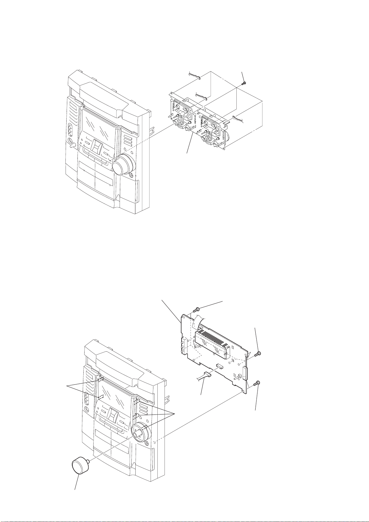
3-6. PANEL BOARD (AEP, UK MODEL)
claws
5
PANEL board
claws
6
CN661
2
three
(+BVTP 2.6
screws
×
8)
3
six
screws
(+BVTP 2.6
4
two
screws
(+BVTP 2.6
×
8)
×
8)
12
1
volume knob
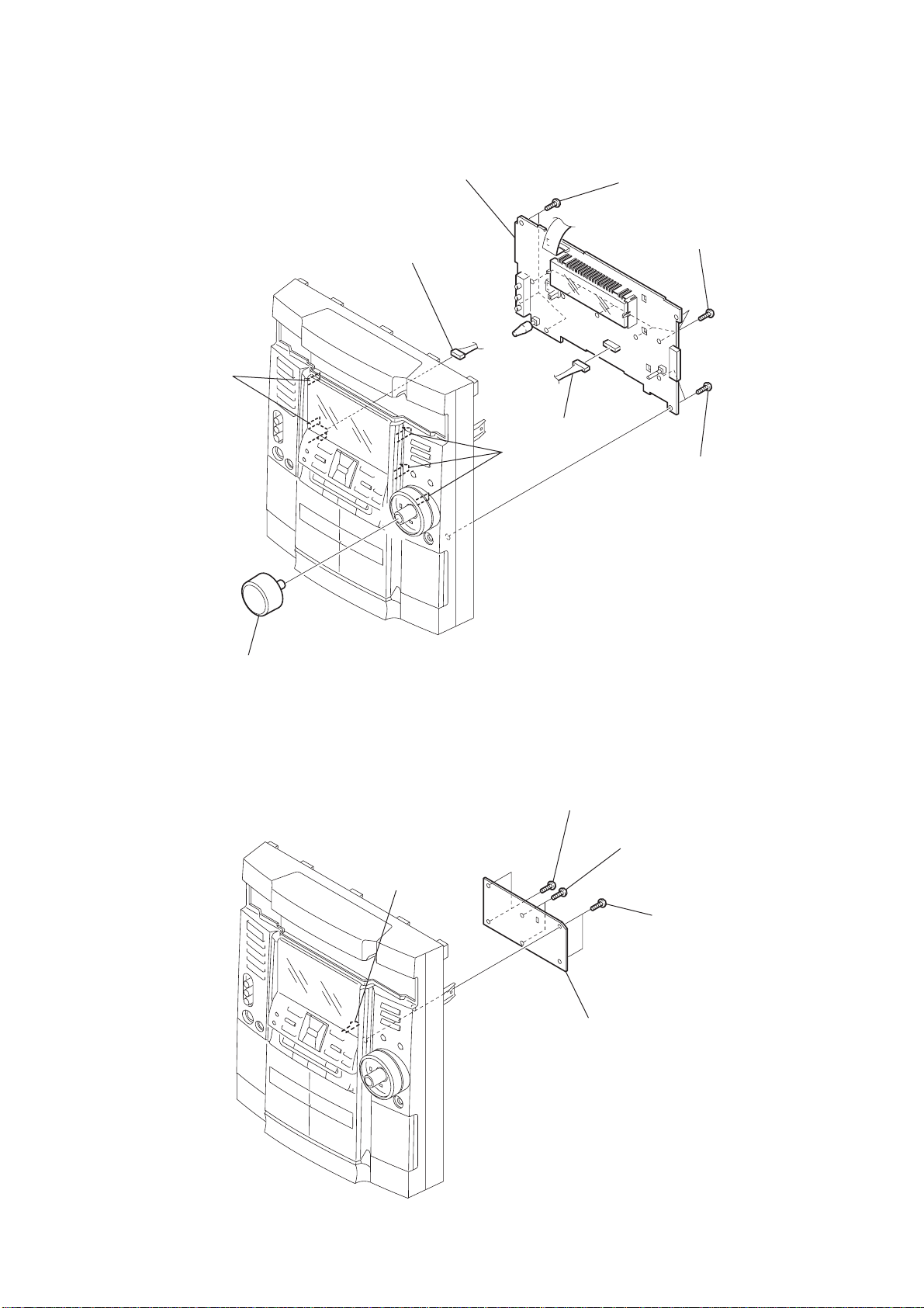
3-7. PANEL BOARD (EXCEPT AEP, UK MODEL)
2
CN663
claws
6
PANEL board
7
CN661
3
three
(+BVTP 2.6
screws
HCD-RG55/RG55S
×
8)
4
six
screws
(+BVTP 2.6
×
8)
3-8. KEY BOARD
1
volume knob
claw
claws
3
two
screws
(+BVTP 2.6
2
two
(+BVTP 2.6
×
8)
screws
5
two
screws
(+BVTP 2.6
×
8)
×
8)
4
KEY board
1
two
screws
(+BVTP 2.6
×
8)
13
HCD-RG55/RG55S
)
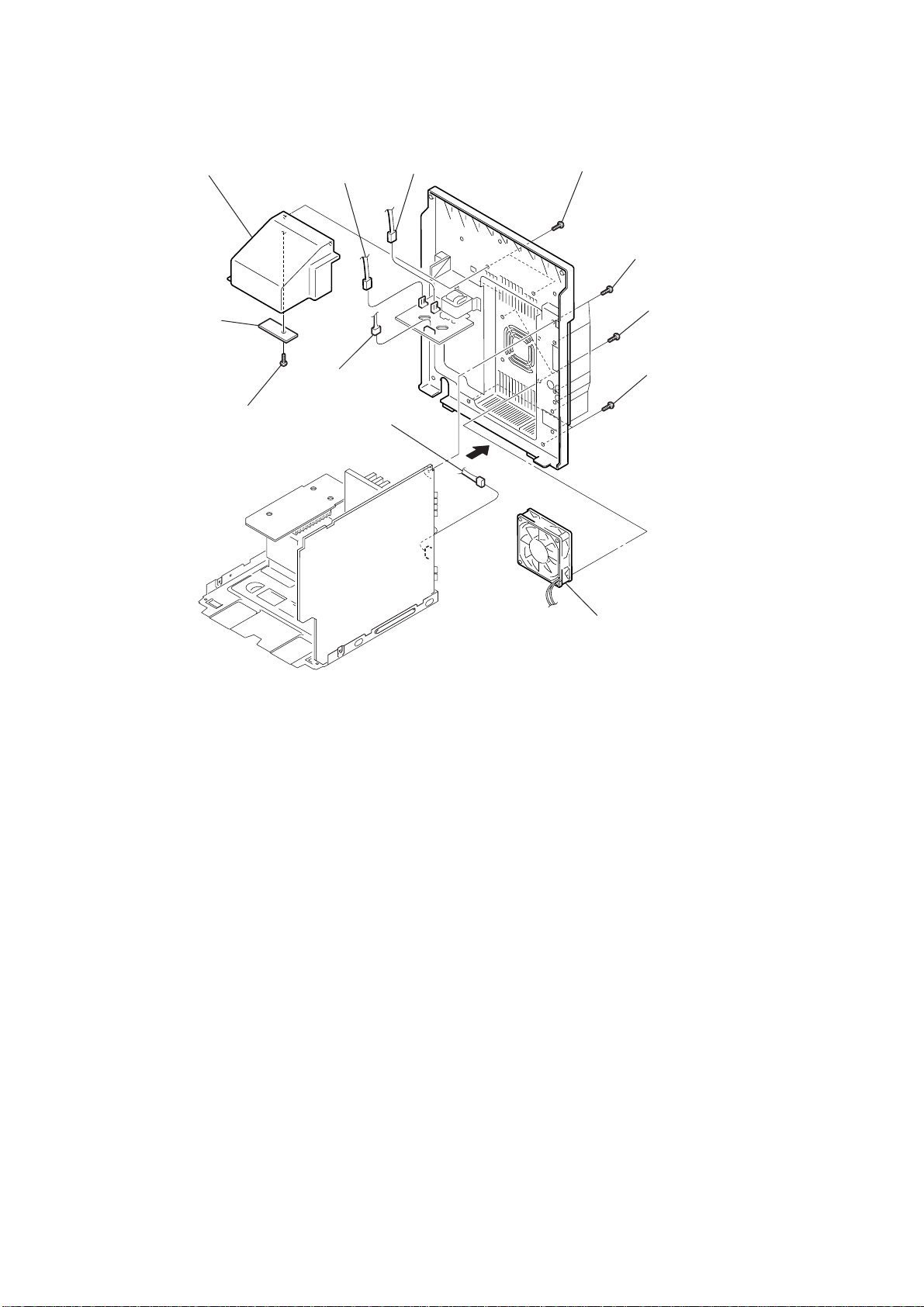
3-9. SENSOR BOARD, DC FAN (FAN961)
6
cover (duct)
8
SENSOR board
7
screw
(+BVTP 2.6
×
1
3
8)
CN901
CN903
4
2
CN2
CN304
qa
5
two screws
(+BVTP 3
9
(+BVTP 3
×
10)
six screws
qs
(+BVTP 3
0
(+BVTT 3
×
two screws
two screws
10)
×
×
16
6)
qd
DC fan (FAN961)
14
3-10. MAIN BOARD, SUB WOOFER BOARD, POWER BOARD
8
two
screws
(+BVTP 3
×
16)
1
qa
(+BVTP 3
qs
POWER board
three
screws
×
0
two
screws
(+BVTP 3
3
CN915
10)
×
2
16)
7
screw
(+BVTP 3
CN508
×
10)
CN509
6
(+BVTP 3
9
SUB WOOFER board
(AEP, UK model)
screw
×
10)
HCD-RG55/RG55S
MAIN board
5
MAIN board
3-11. CD BOARD
3
CN735
2
CN731
(flat type)
1
CN732
4
two
screws
(+BVTP 3
×
10)
5
CD board
4
four
screws
(+BVTP 2.6
×
8)
15
HCD-RG55/RG55S
)
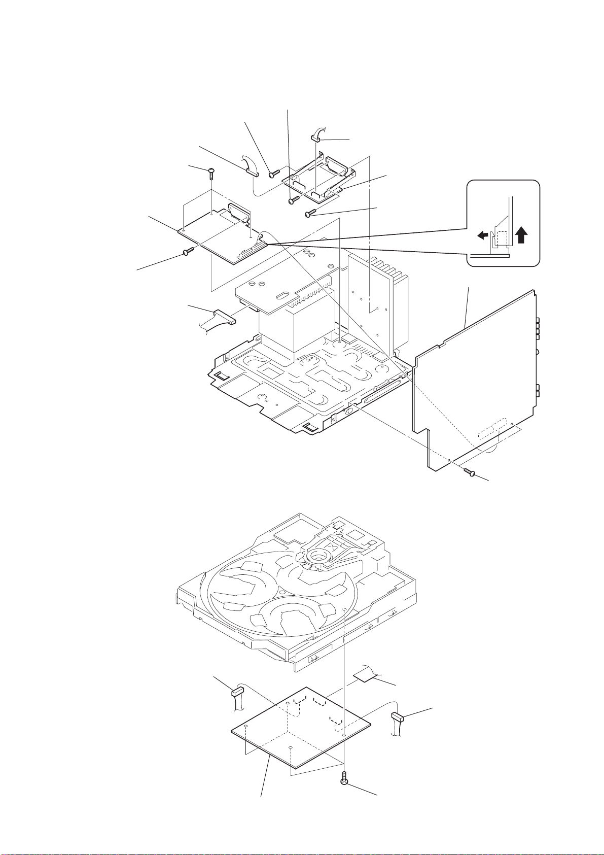
3-12. BASE UNIT
4
holder (BU) assy
qs
3
screw (+PTPWH M2.6)
5
screw (DIA. 12)
base unit
qa
two insulators
0
two
springs (insulator), coil
9
two stoppers (BU)
8
two screws (+BVTP 2.6
1
×
8)
screw (+BVTP 2.6
×
8)
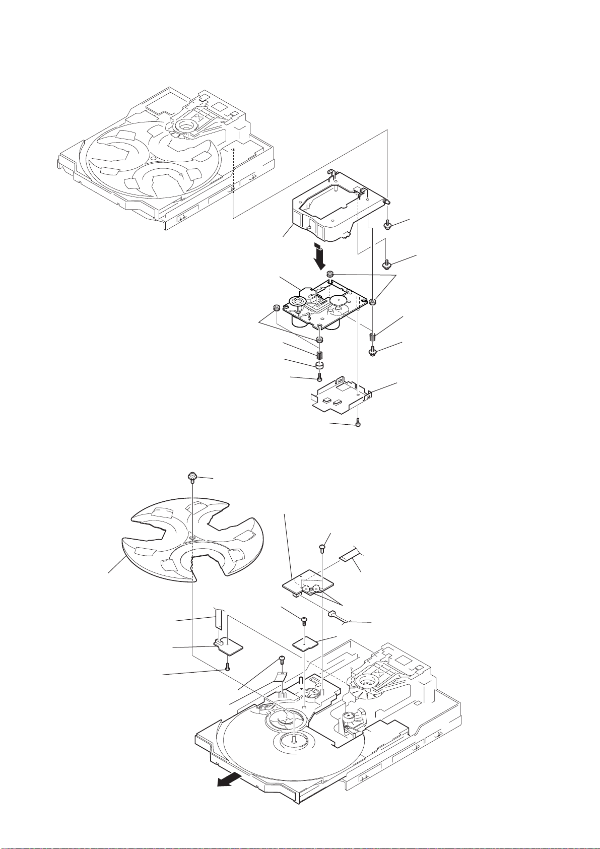
3-13. DRIVER BOARD, MOTOR BOARD, SENSOR (CD) BOARD
qs
screw (+PTPWH 2.6
0
×
8)
MOTOR board
6
two screws (+BVTP 2.6
qs
two insulators
7
two
6
two
2
shild cover
×
springs (insulator), coil
screws (+PTPWH M2.6
8)
16
qd
tray
3
CN702 (flat type)
2
DRIVER board
1
screw
(+BVTP 2.6
×
8)
4
screw (+BVTP 2.6
qf
screw
(+BVTP 2.6
×
8)
5
plate
qa
Pull-out the disc tray.
×
8
CN721(flat type)
8)
7
Remove the two solderings of motor.
9
CN722
qg
SENSOR (CD) board

SECTION 4
TEST MODE
HCD-RG55/RG55S
[Cold Reset]
• The cold reset clears all data including preset data stored in the
RAM to initial conditions. Execute this mode when returning the
set to the customer.
Procedure:
1. Press three buttons x , GROOVE , and ?/1 simultaneously.
2. The fluorescent indicator tube displays “COLD RESET” and
the set is reset.
[CD Ship Mode]
• This mode moves the pickup to the position durable to vibration.
Use this mode when returning the set to the customer after repair.
Procedure:
1. Press ?/1 button to turn the set ON until “STANDBY”
appears.
2. Press CD button and ?/1 button simultaneously.
3. When you releaset he buttons, a message “LOCK” is displayed
on the fluorescent indicator tube, and the CD ship mode is set.
[Hot Reset]
• This mode resets the set with the preset data kept stored in the
memory. The hot reset mode functions same as if the power cord
is plugged in and out.
Procedure:
1. Press three buttons x , GAME EQ , and DISPLAY
simultaneously.
2. The fluorescent indicator tube becomes blank instantaneously,
and the set is reset.
[CD Service Mode]
• This mode can run the CD sled motor freely. Use this mode, for
instance, when cleaning the pickup.
Procedure:
1. Press ?/1 button to turn the set ON.
2. Select the function “CD”.
3. Press three buttons x , GAME EQ , and OPEN/CLOSE
simultaneously.
4. The CD service mode is selected.
5. With the CD in stop status, press the > key to move the pickup
to outside track, or turn the shuttle knob counter-clockwise to
inside track.
6. To exit from this mode, perform as follows:
1) Move the pickup to the most inside track.
2) Cold reset.
Note: • Always move the pickup to most inside track when exiting
from this mode. Otherwise, a disc will not be unloaded.
• Do not run the sled motor excessively, otherwise the gear
can be chipped.
[Change-over of AM Tuner Step between 9 kHz and 10
kHz]
• A step of AM channels can be changed over between 9 kHz and
10 kHz.
Procedure:
1. Press ?/1 button to turn the set ON.
2. Select the function “TUNER”, and press TUNER/BAND
button to select the BAND “MW”.
3. Press ?/1 button to turn the set OFF.
4. Press ENTER and ?/1 buttons simultaneously, and the
display of fluorescent indicator tube changes to “ AM 9 k STEP”
or “ AM 10 k STEP”, and thus the channel step is changed over.
[GC Test Mode]
• This mode is used to check the software version, FL tube, LED,
keyboard, headphone and volume.
Procedure:
1. Press three buttons x , GAME EQ and DISC2
simultaneously.
2. LEDs and fluorescent indicator tube are all turned on.
3. When GAME EQ and DISC2 are pressed at the same time,
the key number check mode starts up. In this mode, the key
numbers of each key series are displayed.
4. In the key check mode, the fluorescent indicator tube displays
“KEY 000”. Each time a button is pressed.
5. When GAME EQ and DISC2 are pressed at the same time,
the key count check mode starts up. In this mode, the message
“KEY CNT @@” is displayed on the FL display tube. When
each button is pressed, the key row number is incremented f irst.
Then the key value is then incremented. However, one the
button is pressed, the key value cannot be counted.
6. When GAME EQ and DISC2 are pressed at the same time,
the headphones check mode starts up. In this mode, the
message “H_P ON” is displayed when the headphones are inserted. When the headphones are not inserted, the message “H_P
OFF” is displayed.
7. When GAME EQ and DISC2 are pressed at the same time,
the volume check mode starts up. In this mode, the message
“VOLUME STOP” is displayed on the FL display tube. When
the volume control knob is rotated in the positive (+) direction,
the message “VOLUME UP” is displayed. When the volume
control knob is rotated in the negative (–) direction, the
message “VOLUME DOWN” is displayed.
8. In order to quit the mode, either press GAME EQ and DISC2
at the same time or press the three buttons at the same time as in
step 1.
9. To exit from this mode, cold reset or disconnect the po wer cord.
17

HCD-RG55/RG55S
[MC Test Mode]
• This mode is used to check operations of the respective sections
of Amplifier, TUNER, CD and Tape.
Procedure:
1. Press the ?/1 button to turn on the set.
2. Press the three buttons of x , GAME EQ and DISC 3
simultaneously.
3. A message “TEST MODE” appears on the FL display tube.
•The messages VACS1 to VACS5 are displayed when the VACS
is changed in this mode.
•The number of repeats of TAPE and CD is set to the infinite
number as the default setting.
4. When MUSIC EQ button is pressed, GEQ increases to its
maximum and a message “GEQ MAX” appears.
5. When MUSIC EQ button is pressed, GEQ decreases to its
minimum and a message “GEQ MIN” appears.
6. When EFFECT ON/OFF button is pressed, GEQ is set to flat
and a message “GEQ FLAT” appears.
7. In the test mode, the default-preset channel is called even when
the TUNER is selected and an attempt is made to call the preset
channel that has beeen stored in memory, by operating the
Shuttle knob. (It means that the memory is cleared.)
8. When a tape is inserted in the Deck B and the T APE B function
is selected, and when the REC PAUSE/START buttton is
pressed twice, recording starts.
The VIDEO function is selected automatically as the input
source.
9. Select the desired loop by pressing the PLAY MODE button
in the TAPE B function. Insert a test tape AMS-110A or AMSRO to Deck A.
10. Press the SPECTRUM button to enter the AMS test mode.
11. After a tape is r ewound first, the FF AMS is checked, and the
mechanism is shut off after detecting the AMS signal twice.
12. Then the REW AMS is checked and the mechanism is shut off
after detecting the AMS signal twice.
13. When the check is complete, a message of either OK or NG
appears.
14. When the two buttons of SPECTR UM and DISC1 are pressed
at the same time in any function modes, either the “VACS ON”
display to enable the VACS function or the “VACS OFF”
display to disable the VACS function can be selected.
15. When you want to exit this mode, press the ?/1 button twice.
The cold reset is enforced at the same time.
[Microprocessor version display]
• If the following operation is performed during the POWER OFF
in the modes other than the POWER SAVE mode (i.e., while the
Demo display shows the watch time).
1. When three buttons of STOP , GAME EQ , MOVIE EQ are
pressed at the same time, the model name and destination are
displayed as “GYO AS1A3”.
2. When three buttons of STOP , GROOVE ar e pressed at the
same time, the MC and the GC microprocessor version
numbers are displayed as “V01.02:01.12.24”.
18
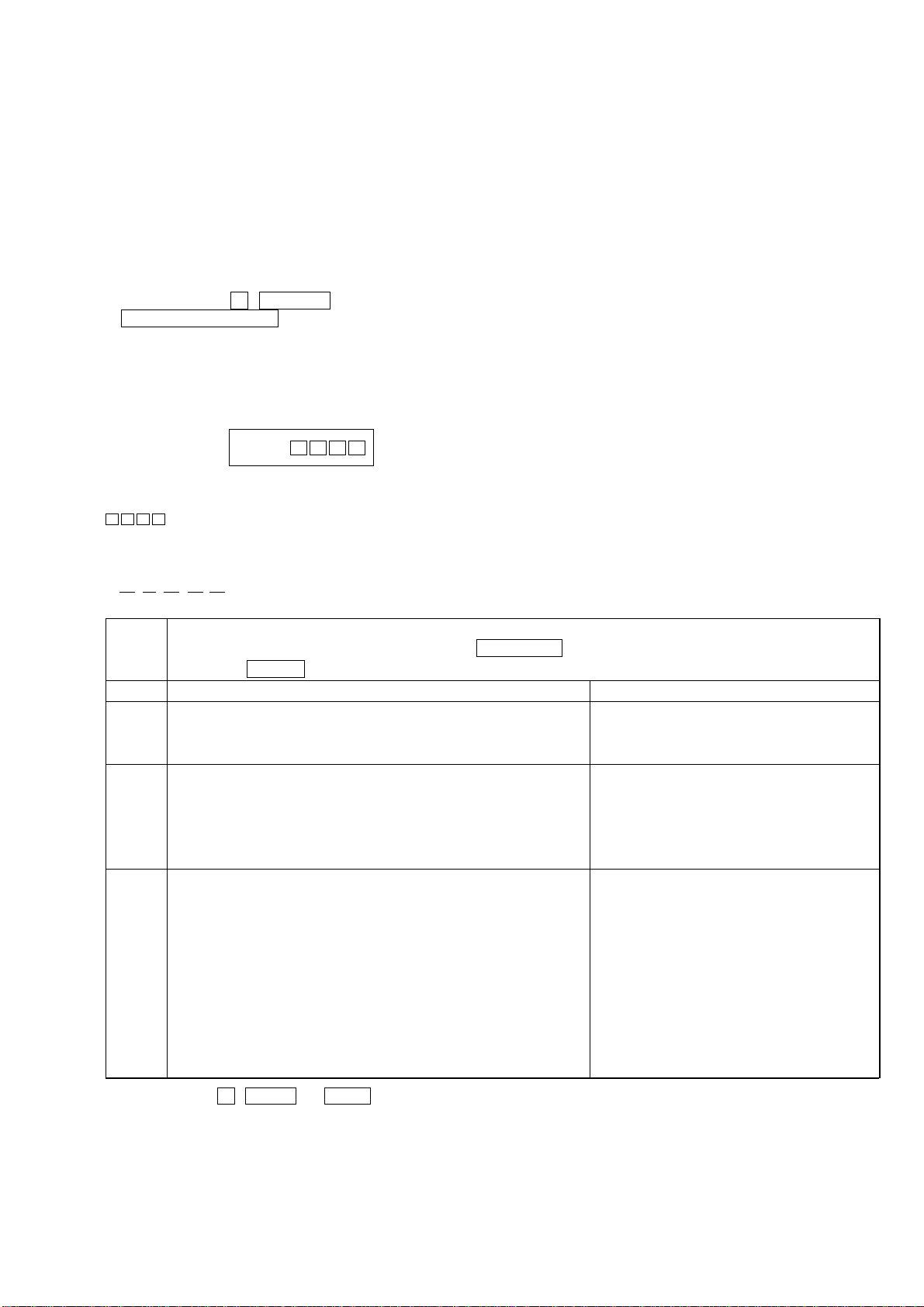
[Aging mode]
This mode can be used for operation check of CD section and tape deck section.
• If an error occurred:
The aging operation stops and display status.
• If no error occurs:
The aging operation continues repeatedly.
1. Operating method of Aging Mode
Turn on the main power and select “CD” of the function.
1) Set a disc in DISC1 tray. Select ALL DISC CONTINUE, and REPEAT OFF.
2) Load the tapes recording use into the decks A and B respectively.
3) Press three buttons x , GAME EQ , and
DISC SKIP EX-CHANGE simultaneously.
4) Aging operations of CD and tape are started at the same time.
5) To exit the aging mode, perform [Cold Reset].
2. Aging Mode in CD section
1) Display state
• No error occurs Display
*
*
*
AGING
*
HCD-RG55/RG55S
Note:
*
*
*
*
: Number of aging operations
Error display
E ** s ## $$ %%
123 45
1 ** The error No. 00 indicates the newest error. As the error No. increases, it means the older error.
When you want to retrieve the error history, press the PLAY MODE button in the case of mechanism error.
Or press the REPEAT button in the case of NO DISC error.
2 s M: Mechanism error D: No disc error
3 ## Don’t care 01: FOCUS ERROR
02: GFS ERROR
03: SETUP ERROR
4 $$ High order digits only 01: NO DISC judgment without chucking retry
D: Stopped during closing due to problems other than mechanism. 02: NO DISC judgment after chucking retry
E: Stopped during opening due to problems other than mechanism.
C: Stopped during chucking due to problems other than mechanism.
F: Stopped during EX-opening due to problems other than mechanism.
5 %% Emergency related errors (High order digits only) Status at the time of NO DISC judgment
1: Stopped during chuck-up (High order digits only)
2: Stopped during chuck-down 1: STOP
3: Time out by EX-OPEN 2: SETUP
5: Time out by EX-CLOSE 3: TOC READ
4: ACCESS
5: PLAY BACK
6: PAUSE
7: MANUAL SEARCH (PLAY)
8: MANUAL SEARCH (PAUSE)
• When the buttons x , ENTER and DISC 1 are pressed simultaneously, number of time of the mechanism error and the NO DISC error
can be checked.
Display: EMC**EDC** ** : Number of times of error (Maximum three times)
EMC : Mechanism error
EDC : No DISC error
•When aging operation is complete, be sure to perform the MC Cold Reset to reset the error history.
19
HCD-RG55/RG55S
2) Operation during aging mode
In the aging mode, the program is executed in the following
sequence.
(1) The disc tray opens and closes.
(2) The mechanism accesses DISC 2 and makes an attempt to read
TOC. Howev er, since there are no discs, a message “CD2 NO
DISC” appears.
(3) The mechanism accesses DISC 3 and a message “CD3 NO
DISC” appears.
(4) The disc tray turns to select a disc1.
(5) A disc is chucked.
(6) TOC of disc is read.
(7) The pickup accesses to the track 1, and playing 2 seconds.
(8) The pickup accesses to the last track, and playing 2 seconds.
(9) Every time when an aging operation of step 1 to step 8 is
*
*
*
complete, the display “ A GING ” value increases as
the number of aging operations is counted up.
(10) Returns to step 1.
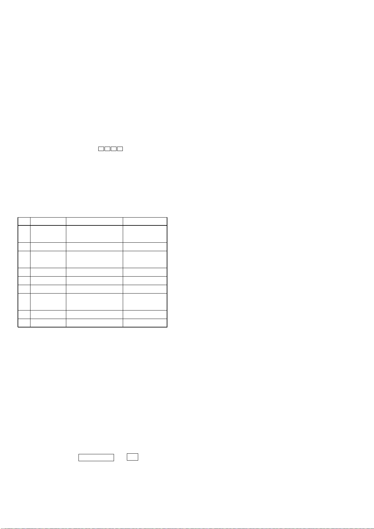
3. Aging Mode in Tape Deck section
1) Display state
• No error occurs
Display action now
• Error occurred
Display action last time
*
NO. Display action Action contents Final timing
TAPE A AG-6 Rewind the TAPE A
1
TAPE B AG-1 Rewind the TAPE B
2TAPE A AG-2 FWD play the TAPE A 2 minutes playing
3TAPE A AG-3 EE the TAPE A
4TAPE A AG-4 REV play the TAPE A 2 minutes playing
5TAPE A AG-5 Rewind the TAPE A The top of tape
6TAPE B AG-2 FWD play the TAPE B 2 minutes playing
7TAPE B AG-3 EE the TAPE B
8TAPE B AG-4 REV paly the TAPE B 2 minutes playing
9TAPE B AG-5 Rewind the TAPE B The top of tape
2) Operation during aging mode
In the aging mode, the program is executed in the following
sequence.
(1) Rewind is executed up to the top of tape A and B.
(2) A tape on FWD side is played for 2 minutes.
(3) FF is executed up to either made for 20 second or the end of
tape.
(4) A tape is reversed, and the tape on REV side is played for 2
minutes.
The tape on the REV side is played in both A and B.
(5) Rewind is executed up to the top of tape.
(6) Returns to step 2, and repeat steps from 2 to 5.
The top of tape
20 second FF or
the end of tape
20 second FF or
the end of tape
[Function Change Mode]
* elect either VIDEO or MD of the external FUNCTION input.
Procedure:
1. Turn on the power.
2. Press the two buttons MD (VIDEO) and ?/1 at the same
time.
The main power is turned on and the other function of the
previous function is selected and displayed. “MD” or “VIDEO”.
20
SECTION 5
l
l
MAIN BOARD Component side
RV101: FM TUNED LEVEL
T101:NULL
IFT101:AM IF
ELECTRICAL ADJUSTMENTS
HCD-RG55/RG55S
TUNER SECTION
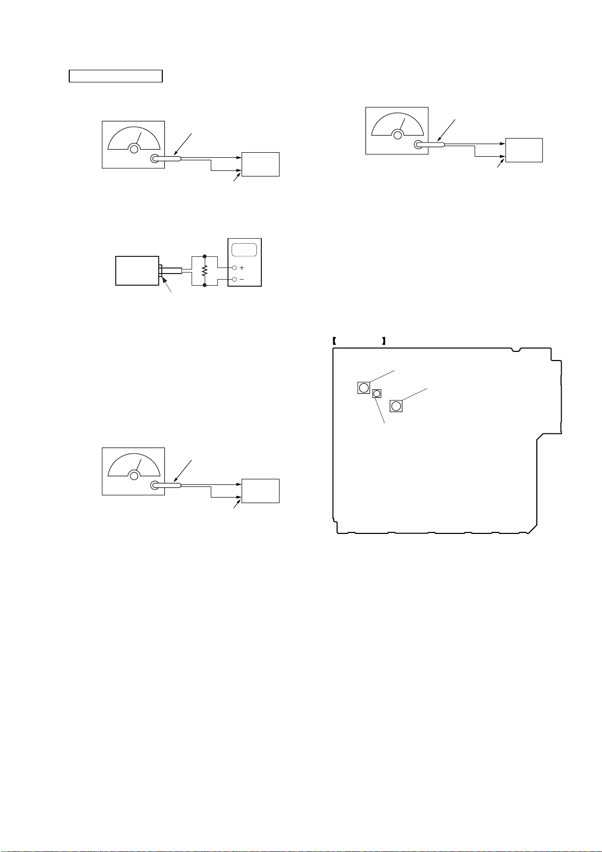
AM IF Adjustment
AM RF Signalgenerator
75
Ω
coaxial
set
30% amplitude
Modulation by
400Hz signal
Output level : as low as possible
set
Procedure:
1. Set the frequency of the AM RF signal generator to 1000 kHz
(at 10 kHz step) or 999 kHz (at 9 kHz step).
2. Tune the set to AM 1000 kHz (at 10 kHz step) or 999 kHz (at 9
kHz step).
3. Adjust IFT101 so that the reading on level meter becomes in
maximum.
AM ANTENNA terminal
(JK101)
level meter
Ω
16
PHONES jack(JK801)
Null Adjustment
FM RF Signalgenerator
Ω
coaxial
75
set
Carrier frequency : 98MHz
Modulation : AUDIO 1kHz,75kHz
Output level : 60dB (at 75
deviation (100%)
Ω
open)
FM ANTENNA termina
(JK101)
Procedure:
1. Supply a 98 MHz signal at 60 dB from the ANTENNA
terminal.
2. Tune the set to 98 MHz.
3. Measure voltage between pin 21 and pin 23 of IC 101. Adjust
T101 ubtil the voltage becomes 0 V.
Adjustment Location: MAIN board
Adjustment Location:
FM Tuned Level Adjustment
FM RF Signalgenerator
Carrier frequency : 98MHz
Modulation : AUDIO 1kHz,75kHz
Output level : 28dB (at 75
Procedure:
1. Supply a 98 MHz signal at 28 dB from the ANTENNA
terminal.
2. Tune the set to 98 MHz.
3. Adjust RV101 to the point (moment) when the TUNED
indicator will change from going off to going on.
Adjustment Location: MAIN board
Ω
75
deviation (100%)
Ω
open)
coaxial
set
FM ANTENNA termina
(JK101)
21
HCD-RG55/RG55S
CD SECTION
Note:
1. CD Block is basically designed to operate without adjustment.
Therefore, check each item in order given.
2. Use YEDS-18 disc (3-702-101-01) unless otherwise indica ted.
3. Use an oscilloscope with more than 10 MΩ impedance.
4. Clean the object lens by an applicator with neutral detergent
when the signal level is low than specified value with the
following checks.
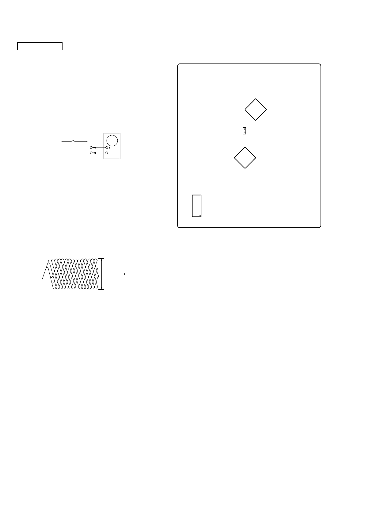
RF Level Check
CD board
TP731 pin
GND
Procedure:
1. Connect oscilloscope to TP731 pin 2.
2. Turned Power switch on.
3. Load a disc (YEDS-18) and playback, the number five track.
4. Confirm that oscilloscope waveform is clear and check RF
signal level is correct or not.
Note: Clear RF signal waveform means that the shape “ ” can be
clearly distinguished at the center of the waveform.
Oscilloscope
2
s
Adjustment Location:
- CD BOARD (Conductor Side) -
TP731
48
49
IC781
15 14
21 8
22 7
28 1
64
1
1
2
33
IC731
64
49
16
32
1
IC751
17
17
16
48
33
32
RF signal waveform
VOLT/DIV:200mV
TIME/DIV:500ns
level:1.7 0.3Vp-p
22
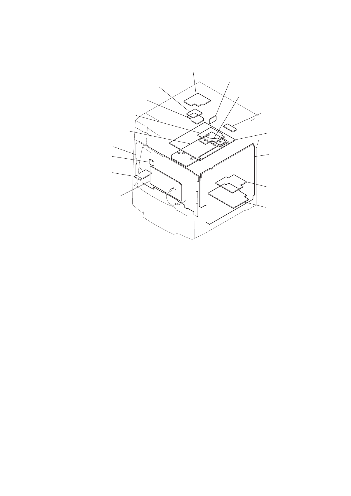
6-1. CIRCUIT BOARDS LOCATION
d
SENSOR (CD)board
DRIVER board
HCD-RG55/RG55S
SECTION 6
DIAGRAMS
MOTOR board
VIDEO OUT board
(SPDL) MOTOR board
SUB TRANS board
TRANS board
PANEL board
REMOTE board
MIC board
(EXCEPT AEP, UK model)
KEY board
SENSOR board
CD board
MAIN board
SUB WOOFER boar
(AEP, UK model)
POWER AMP board
23
 Loading...