

Sony HCDNXM-3 Service manual
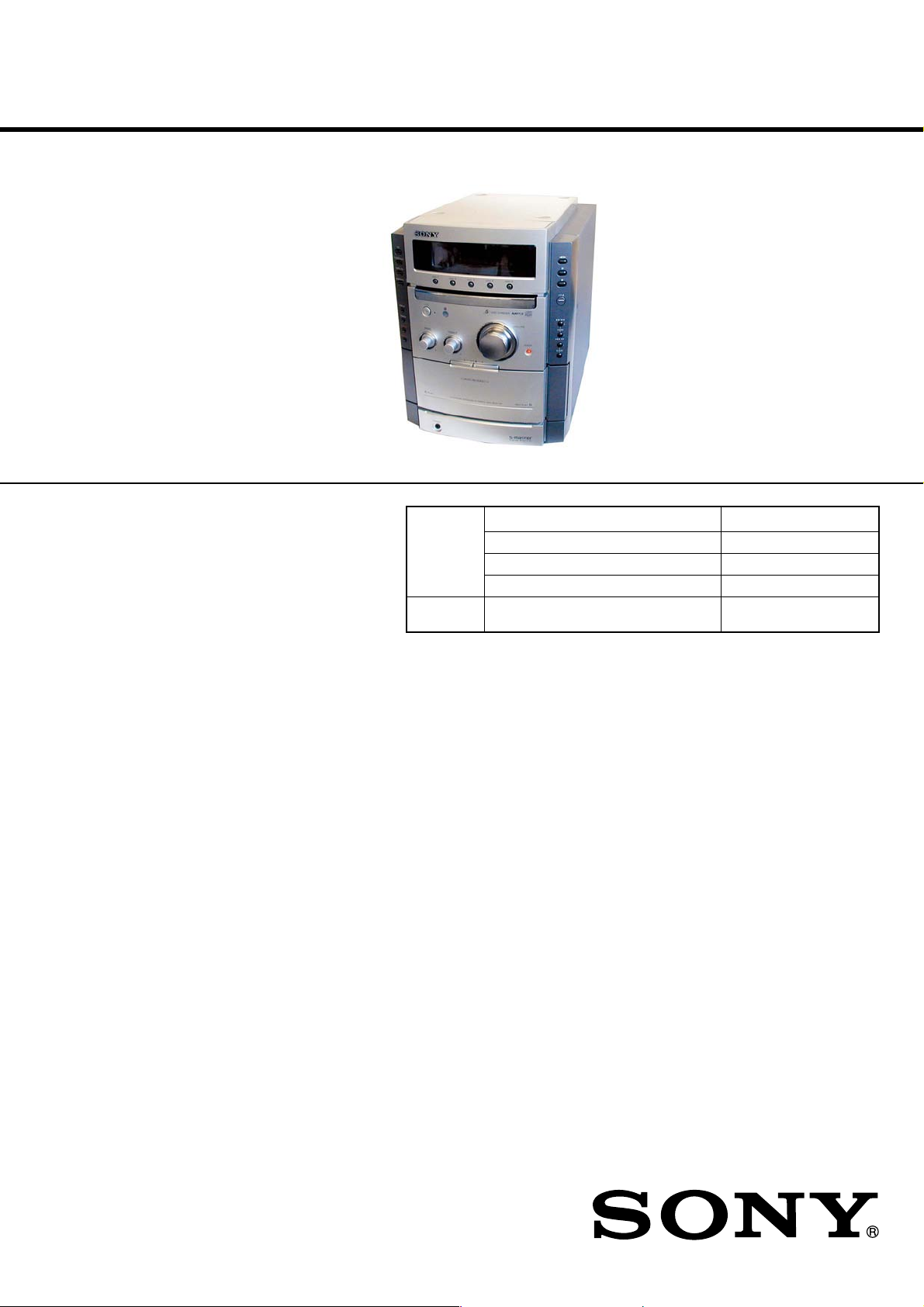
HCD-CPX22/NXM3
SERVICE MANUAL
Ver. 1.1 2005.05
• HCD-CPX22 is the Amplifier, CD player,
tape deck and tuner section in CMT-CPX22.
• HCD-NXM3 is the Amplifier, CD player,
tape deck and tuner section in MHC-NXM3.
Photo : HCD-CPX22
Model Name Using Similar Mechanism NEW
CD CD Mechanism Type CDM81B-F1BD81A
Section Base Unit Name BU-F1BD81A
Optical Pick-up Name KSM-215DCP/C2NP
TAPE
Section
Model Name Using Similar Mechanism NEW
US Model
HCD-CPX22
AEP Model
HCD-CPX22/NXM3
UK Model
E Model
HCD-CPX22
SPECIFICATIONS
Amplifier section
For the U.S.A. model
AUDIO POWER SPECIFICATIONS
HCD-CPX22
POWER OUTPUT AND TOTAL HARMONIC DISTORTION:
With 4-ohm loads, both channels driven, from 120 – 10,000 Hz;
rated 100 watts per channel minimum RMS power, with no more
than 10% total harmonic distortion from 250 milliwatts to rated
output.
Other models:
The following measured at AC 120 – 127/220 – 240 V, 50/60 Hz
(Saudi Arabian model only)
The following measured at AC 230 V, 50/60 Hz (European and
Russian models only)
The following measured at AC 120/220 – 240 V, 50/60 Hz (except
for European, Russian and Saudi Arabian models)
DIN power output (rated): 75 + 75 watts (4 ohms at 1 kHz, DIN)
Continuous RMS power output (reference):
100 + 100 watts
(4 ohms at 1 kHz, 10% THD)
Inputs
VIDEO/MD IN (phono jacks):
Outputs
DIGITAL (OPTICAL) OUT: Optical Wavelength: 660 nm
PHONES (mini jack): accepts headphones with an
Sensitivity 250/450 mV, impedance
47 kilohms
impedance of 8 ohms or more
SPEAKER: Use only the supplied speakers
SS-CPX22
(HCD-CPX22)
SS-NXM3
(HCD-NXM3)
CD player section
System
Laser Semiconductor laser
Frequency response 2 Hz – 20 kHz (±0.5 dB)
Tape deck section
Recording system 4-track 2-channel stereo
Frequency response 50 – 13,000 Hz (±3 dB), using Sony
Compact disc and digital audio system
(λ=770 – 810 nm)
Emission duration: continuous
TYPE I cassettes
– Continued on next page –
HCD-CPX22
MICRO Hi-Fi COMPONENT SYSTEM
HCD-NXM3
MiNi Hi-Fi COMPONENT SYSTEM
9-877-828-02
2005E02-1
© 2005.05
Sony Corporation
Audio Group
Published by Sony Engineering Corporation
HCD-CPX22/NXM3
Tuner section
FM stereo, FM/AM superheterodyne tuner
FM tuner section
Tuning range
U.S.A. model: 87.5 – 108.0 MHz (100-kHz step)
Russian model: 65.0 – 74.0 MHz (10-kHz step)
(There is no stereo effect)
87.5 – 108.0 MHz (50-kHz step)
Other models: 87.5 – 108.0 MHz (50-kHz step)
Antenna FM lead antenna
Antenna terminals 75 ohms unbalanced
Intermediate frequency 10.7 MHz
AM tuner section
Tuning range
Pan-American model: 530 – 1,710 kHz
(with the tuning interval set at 10 kHz)
531 – 1,710 kHz
(with the tuning interval set at 9 kHz)
European, Russian and Saudi Arabian models:
531 – 1,602 kHz
(with the tuning interval set at 9 kHz)
Other models: 531 – 1,602 kHz
(with the tuning interval set at 9 kHz)
530 – 1,710 kHz
(with the tuning interval set at 10 kHz)
Antenna AM loop antenna
Antenna terminals External antenna terminal
Intermediate frequency 450 kHz
SAFETY CHECK-OUT
After correcting the original service problem, perform the following
safety checks before releasing the set to the customer:
Check the antenna terminals, metal trim, “metallized” knobs, screws,
and all other exposed metal parts for AC leakage. Check leakage as
described below.
LEAKAGE
The AC leakage from any exposed metal part to earth ground and
from all exposed metal parts to any exposed metal part having a
return to chassis, must not exceed 0.5 mA (500 microamperes).
Leakage current can be measured by any one of three methods.
1. A commercial leakage tester, such as the Simpson 229 or RCA
WT-540A. Follow the manufacturers’ instructions to use these
instruments.
2. A battery-operated AC milliammeter. The Data Precision 245
digital multimeter is suitable for this job.
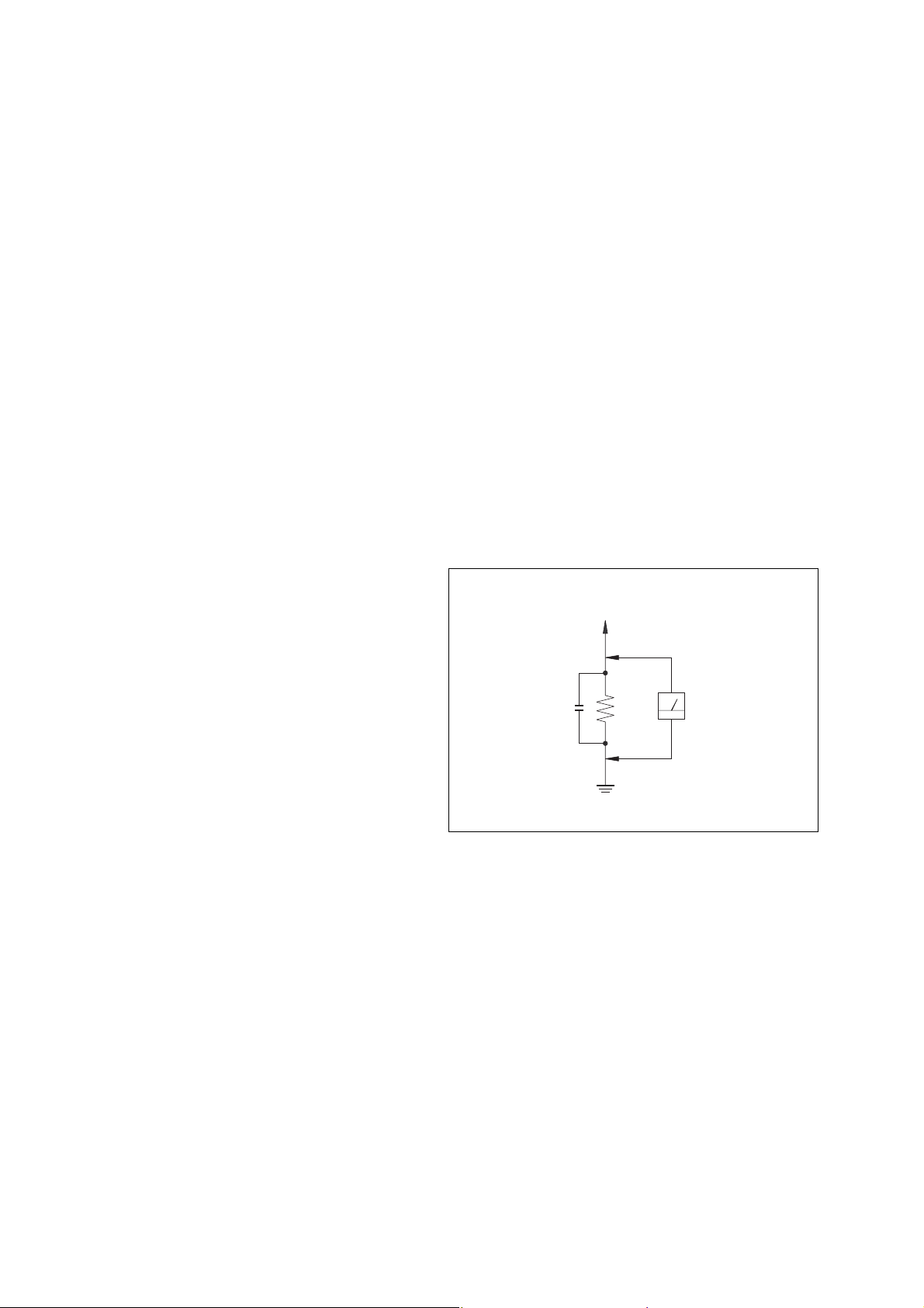
3. Measuring the voltage drop across a resistor by means of a
VOM or battery-operated AC voltmeter. The “limit” indication
is 0.75 V, so analog meters must have an accurate low-voltage
scale. The Simpson 250 and Sanwa SH-63Trd are examples
of a passive VOM that is suitable. Nearly all battery operated
digital multimeters that have a 2V AC range are suitable. (See
Fig. A)
General
Power requirements
U.S.A. model: 120 V AC, 60 Hz
European and Russian models:
230 V AC, 50/60 Hz
Saudi Arabian model: 120 – 127 V or 220 – 240 V AC,
50/60 Hz
Adjustable with voltage selector
Other models: 120 V, 220 – 240 V AC, 50/60 Hz
Adjustable with voltage selector
Power consumption
U.S.A. model: 65 watts
European and Russian models:
65 watts
0.3 watts (in Power Saving mode)
Other models: 65 watts
Dimensions (w/h/d) incl. projecting parts and controls
Amplifier/Tuner/Tape/CD section:
Approx. 230 x 292 x 355 mm
Mass
Amplifier/Tuner/Tape/CD section:
Approx. 6.1 kg
Supplied accessories Remote Commander (1)
Size AA (R6) batteries (2)
AM loop antenna (1)
FM lead antenna (1)
Speaker pads (8)
Speaker cords
To Exposed Metal
Par ts on Set
AC
0.15 µF
Fig. A. Using an AC voltmeter to check AC leakage.
1.5 k Ω
Earth Ground
Voltmeter
(0.75 V)
Design and specifications are subject to change without notice.
2

TABLE OF CONTENTS
HCD-CPX22/NXM3
1. SERVICING NOTES ................................................ 4
2. GENERAL
Location of Controls ........................................................ 5
3. DISASSEMBLY
3-1. Disassembly Flow ........................................................... 7
3-2. Case ................................................................................. 8
3-3. Main Board, Front Panel Section .................................... 8
3-4. Tape Mechanism Deck .................................................... 9
3-5. Panel Board ..................................................................... 9
3-6. Back Panel ....................................................................... 10
3-7. CD Mechanism Deck (CDM81B-F1BD81A) ................. 10
3-8. S-Master Board................................................................ 11
3-9. Tray.................................................................................. 11
3-10. M761 (LD/ST Motor), M762 (BU U/D Motor) .............. 12
3-11. Base Unit (BU-F1BD81A) .............................................. 12
3-12. BD Board ......................................................................... 13
4. TEST MODE .............................................................. 14
5. MECHANICAL ADJUSTMENTS ....................... 17
6. ELECTRICAL ADJUSTMENTS
Deck section .................................................................... 17
CD Section ...................................................................... 18
7. DIAGRAMS
7-1. Circuit Board Location .................................................... 21
7-2. Block Diagram – CD Servo Section –............................ 22
7-3. Block Diagram – Tuner/Tape Deck Section – ................ 23
7-4. Block Diagram – Main Section – ................................... 24
7-5. Block Diagram – S-Master Section – ............................. 25
7-6. Printed Wiring Board – BD Board – .............................. 26
7-7. Schematic Diagram – BD Board – ................................. 27
7-8. Printed Wiring Board – CD Mechanism Board – ........... 28
7-9. Schematic Diagram – CD Mechanism Board – ............. 29
7-10. Printed Wiring Boards – Main Board –.......................... 30
7-11. Schematic Diagram – Main Board (1/3) – ..................... 31
7-12. Schematic Diagram – Main Board (2/3) – ..................... 32
7-13. Schematic Diagram – Main Board (3/3) – ..................... 33
7-14. Printed Wiring Boards – Panel Board – ......................... 34
7-15. Schematic Diagram – Panel Board – ............................... 35
7-16. Printed Wiring Board – Disc SW, Vol, HP Board – ....... 36
7-17. Schematic Diagram – Disc SW, Vol, HP Board – .......... 37
7-18. Printed Wiring Board – S-Master Board – ..................... 38
7-19. Schematic Diagram – S-Master Board – ........................ 39
7-20. IC Block Diagram ........................................................... 40
7-21. IC Pin Function Description ............................................ 41
8. EXPLODED VIEWS
8-1. Main Section.................................................................... 47
8-2. Front Panel Section ......................................................... 48
8-3. Chassis Section ................................................................ 49
8-4. CD Mechanism Deck Section-1
(CDM81B-F1BD81A) .................................................... 50
8-5. CD Mechanism Deck Section-2
(CDM81B-F1BD81A) .................................................... 51
8-6. CD Mechanism Deck Section-3
(CDM81B-F1BD81A) .................................................... 52
9. ELECTRICAL PARTS LIST ................................ 53
Notes on chip component replacement
• Never reuse a disconnected chip component.
• Notice that the minus side of a tantalum capacitor may be
damaged by heat.
Flexible Circuit Board Repairing
• Keep the temperature of soldering iron around 270˚C
during repairing.
• Do not touch the soldering iron on the same conductor of the
circuit board (within 3 times).
• Be careful not to apply force on the conductor when soldering
or unsoldering.
CAUTION
Use of controls or adjustments or performance of procedures
other than those specified herein may result in hazardous
radiation exposure.
This appliance is classified as
a CLASS 1 LASER product.
This label is located on the rear
exterior.
SAFETY-RELATED COMPONENT WARNING!!
COMPONENTS IDENTIFIED BY MARK 0 OR DOTTED LINE WITH
MARK 0 ON THE SCHEMATIC DIAGRAMS AND IN THE PARTS
LIST ARE CRITICAL TO SAFE OPERATION. REPLACE THESE
COMPONENTS WITH SONY PARTS WHOSE PART NUMBERS
APPEAR AS SHOWN IN THIS MANUAL OR IN SUPPLEMENTS
PUBLISHED BY SONY.
3
HCD-CPX22/NXM3
SECTION 1
SERVICING NOTES
NOTES ON HANDLING THE OPTICAL PICK-UP BLOCK
OR BASE UNIT
The laser diode in the optical pick-up block may suffer electrostatic
break-down because of the potential difference generated by the
charged electrostatic load, etc. on clothing and the human body.
During repair, pay attention to electrostatic break-down and also
use the procedure in the printed matter which is included in the
repair parts.
The flexible board is easily damaged and should be handled with
care.
NOTES ON LASER DIODE EMISSION CHECK
The laser beam on this model is concentrated so as to be focused on
the disc reflective surface by the objective lens in the optical pickup block. Therefore, when checking the laser diode emission, observe
from more than 30 cm away from the objective lens.
LASER DIODE AND FOCUS SEARCH OPERATION CHECK
Carry out the “S curve check” in “CD section adjustment” and check
that the S curve waveform is output several times.
•Abbreviation
E3 : 240 V AC Area in E model
E51 : Chilean and Peruvian model
EA : Saudi Arabia model
RU : Russian model
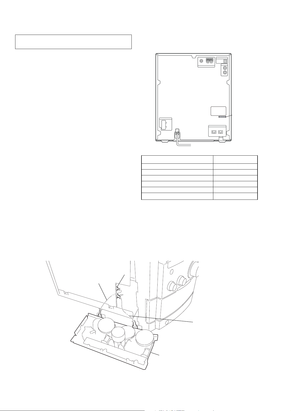
• MODEL IDENTIFICATION
– Back Panel –
PAR T No.
MODEL PART No.
AEP, UK models 4-253-358-0[]
RU model 4-253-358-1[]
E3 model 4-253-358-2[]
E51 model 4-253-358-3[]
US model 4-253-358-4[]
EA model 4-253-358-5[]
• SERVICE POSITION FOR TAPE MECHANISM DECK
CN301
Jig (J-2501-270-A)
CN302
Jig (J-2501-271-A)
tape mechanism deck
4
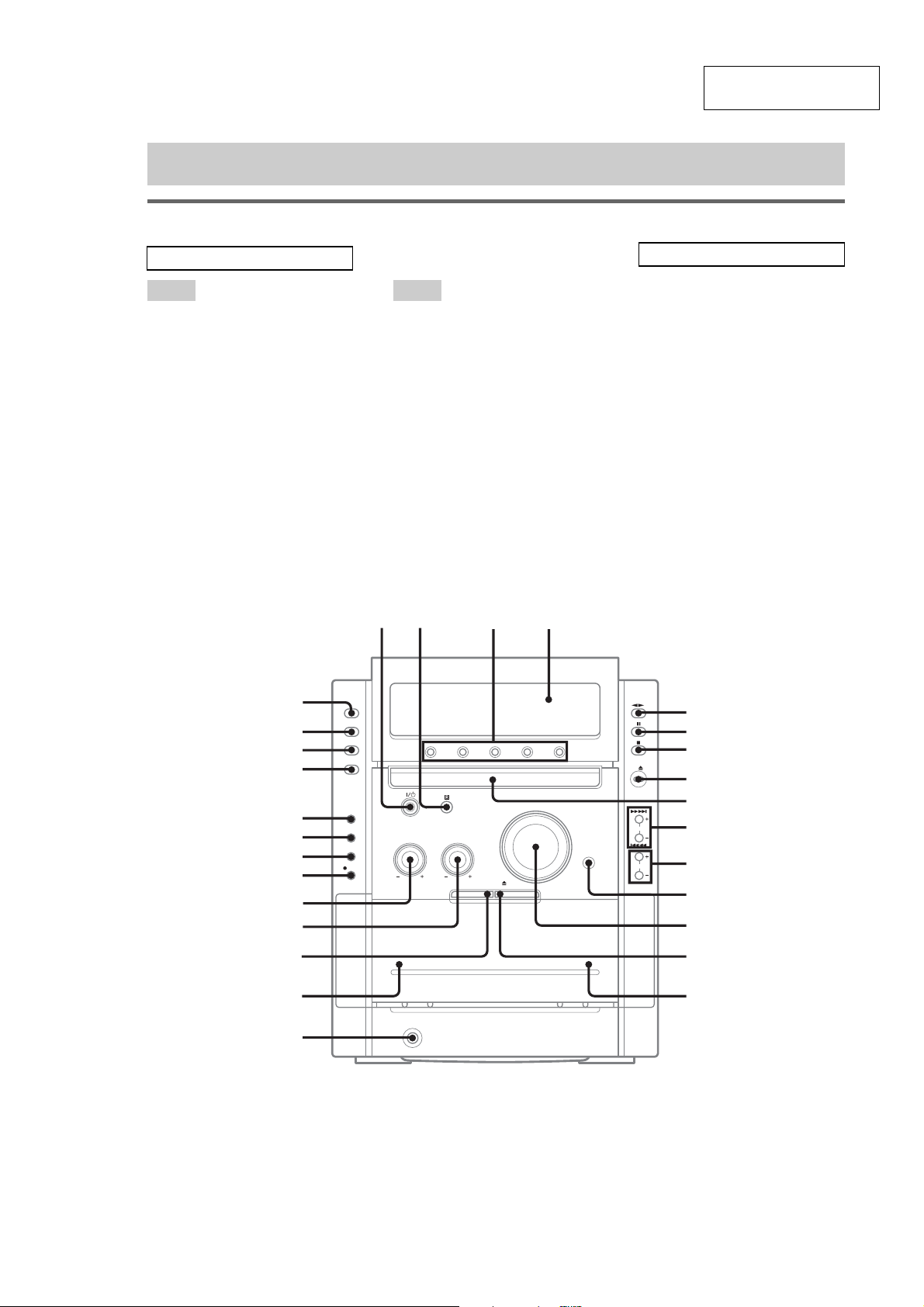
LOCATING THE CONTROLS
12 3 4
List of button locations and reference pages
Main u nit
SECTION 2
GENERAL
HCD-CPX22/NXM3
This section is extracted
from instruction manual.
ALPHABETICAL ORDER
A – O P – Z
ALBUM +/– qa
BASS control w;
CD wk
CD SYNC ws
Deck A qj
Deck B qg
DIMMER wd
DISC 1 – 5 3
Disc tray 9
DISPLAY wf
Display window 4
DSGX qs
PHONES jack qh
Remote sensor 2
TAPE A/B wh
TREBLE control ql
TUNER/BAND wj
TUNING +/– 0
VIDEO/MD wg
VOLUME control qd
BUTTON DESCRIPTIONS
?/1 (power) 1
nN (play) 5
X (pause) 6
x (stop) 7
CD Z (eject) 8
.m/M> (rewind/fast
forward, go back/go forward)
0
TAPE Z B(eject) qf
A TAPE Z (eject) qk
z START wa
wk
wj
wh
wg
wf
wd
ws
wa
w;
ql
qk
qj
qh
5
6
7
8
9
0
qa
qs
qd
qf
qg
5
HCD-CPX22/NXM3
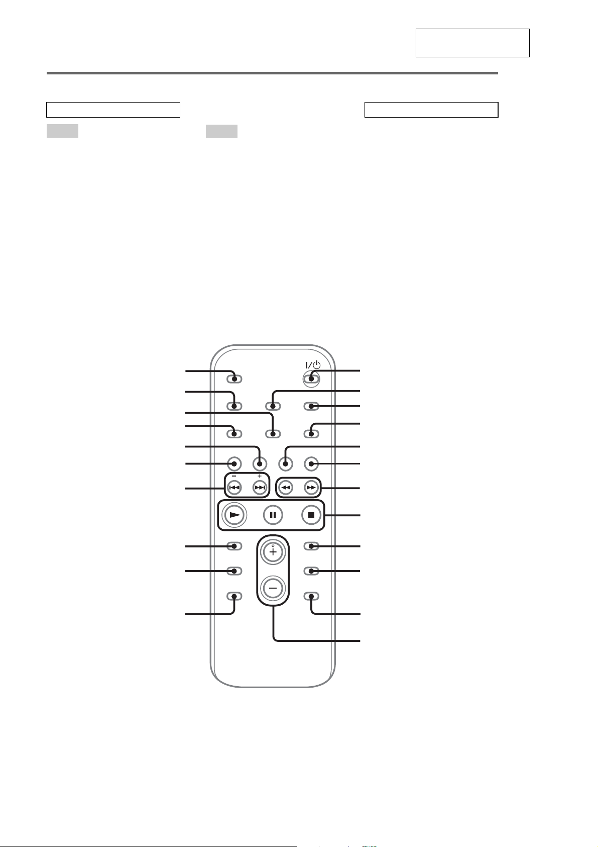
Remote co ntrol
This section is extracted
from instruction manual.
ALPHABETICAL ORDER
A – E
ALBUM – qd
ALBUM + qa
CD qk
CLEAR qg
CLOCK/TIMER SELECT 2
CLOCK/TIMER SET 3
DISC SKIP 0
DISPLAY wa
ENTER 9
EQ qf
ws
wa
F – Z
FM MODE 4
FUNCTION 6
PLAY MODE w;
REPEAT 4
SLEEP ws
TAPE qj
TUNER BAND 5
TUNER MEMORY ql
TUNING MODE w;
VOLUME +/– qs
BUTTON DESCRIPTIONS
?/1 (power) 1
m/M (rewind/fast forward)
N (play) 8
X (pause) 8
x (stop) 8
./> (go back/go forward)
–/+ (tuning) qh
1
2
7
qh
w;
ql
qk
qj
qh
qg
qf
qd
3
4
5
6
7
8
9
q;
qa
qs
6
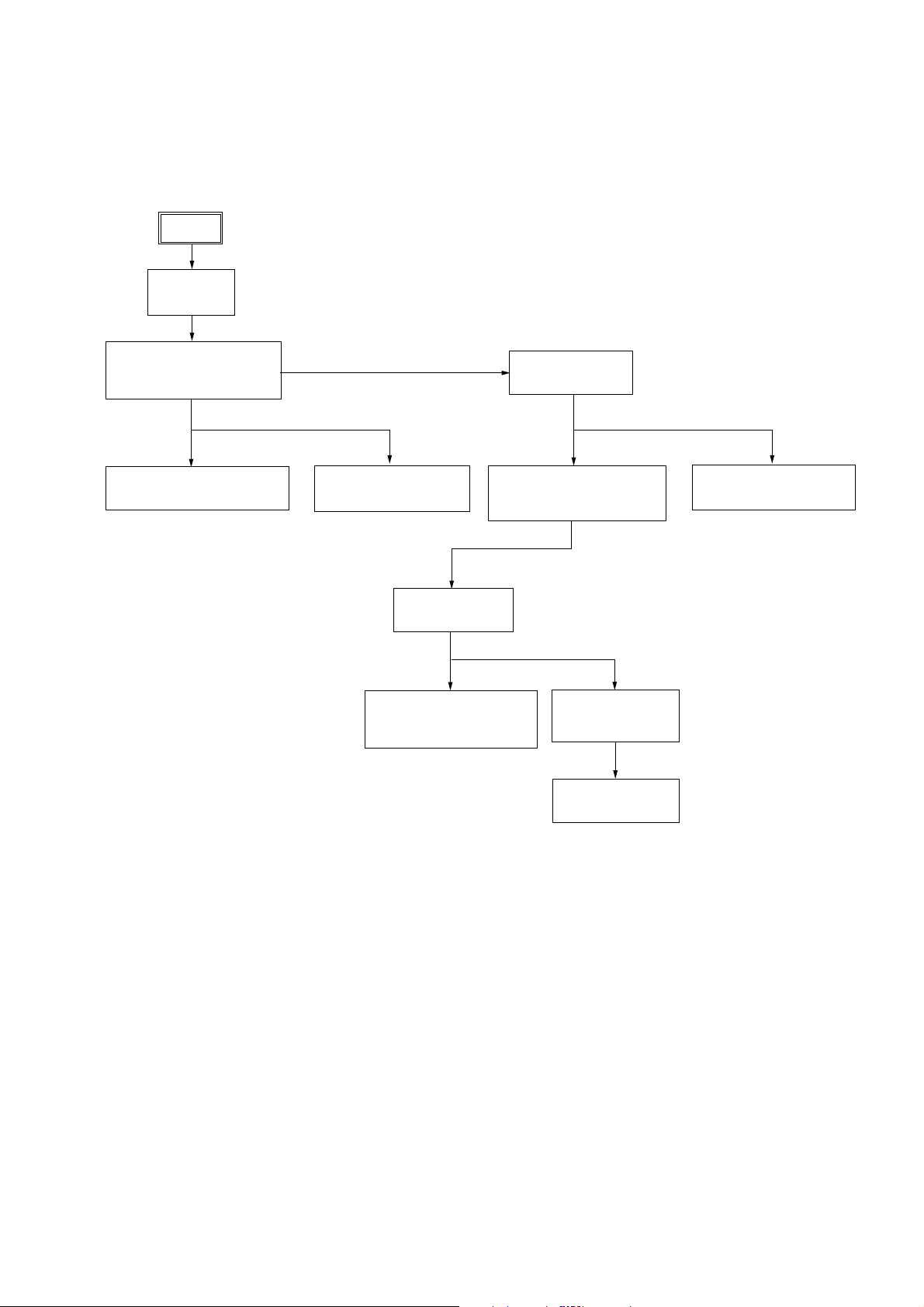
• This set can be disassembled in the order shown below.
3-1. DISASSEMBLY FLOW
SET
3-2.CASE
(Page 8)
HCD-CPX22/NXM3
SECTION 3
DISASSEMBLY
3-3.MAIN BOARD,
FRONT PANEL SECTION
(Page 8)
3-4.TAPE MECHANISM DECK
(Page 9)
3-5.PANEL BOARD
(Page 9)
3-9.TRAY
(Page 11)
3-10.M761 (LD/ST MOTOR),
M762 (BU U/D MOTOR)
(Page 12)
3-6.BACK PANEL
(Page 10)
3-7.CD MECHANISM DECK
(CDM81B-F1BD81A)
(Page 10)
3-11.BASE UNIT
(BU-F1BD81A)
(Page 12)
3-12.BD BOARD
(Page 13)
3-8.S-MASTER BOARD
(Page 11)
7
HCD-CPX22/NXM3
)
)
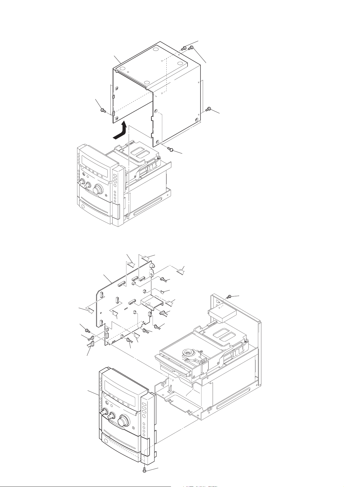
Note: Follow the disassembly procedure in the numerical order given.
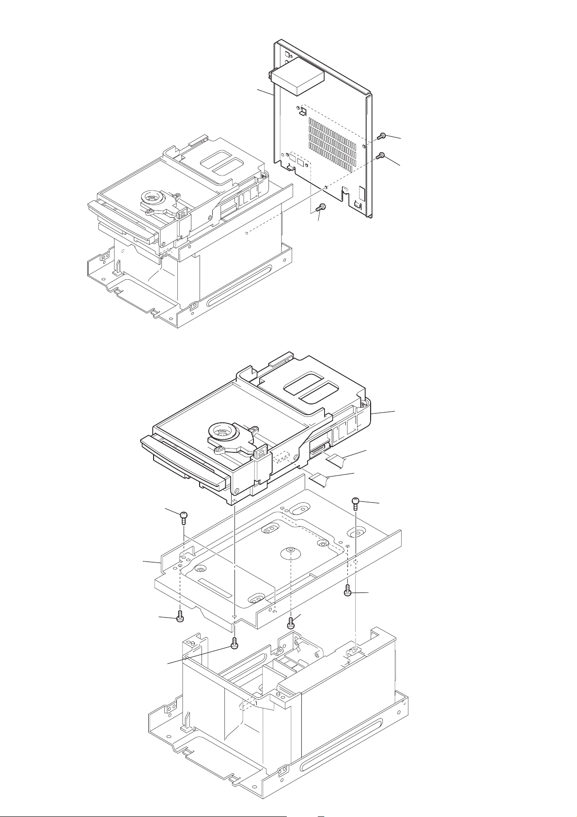
3-2. CASE
2
three
(CASE 3 TP2)
screws
7
CASE
6
4
two
screws
(+BVTP 3X8)
5
screw
(+BVTP 3X8)
1
three
(CASE 3 TP2)
screws
3
two
screws
(+BVTP 3X8
3-3. MAIN BOARD, FRONT PANEL SECTION
qh
CN371
3
MAIN board
qj
CN109
1
two
screws
(+BVTP 3X8)
4
connector
(CN301)
5
connector
(CN302)
w;
front panel section
qk
CN110
6
(CN107)
8
(CN304)
7
CN303
connector
qg
CN372
9
(CN105)
connector
qf
qd
connector
(CN401)
qs
CN112
qa
CN106
0
connector
(CN101)
connector
CN204
2
two
(+BVTP 2.6X8
screws
ql
two
screws
8
(+BVTP 3X8)
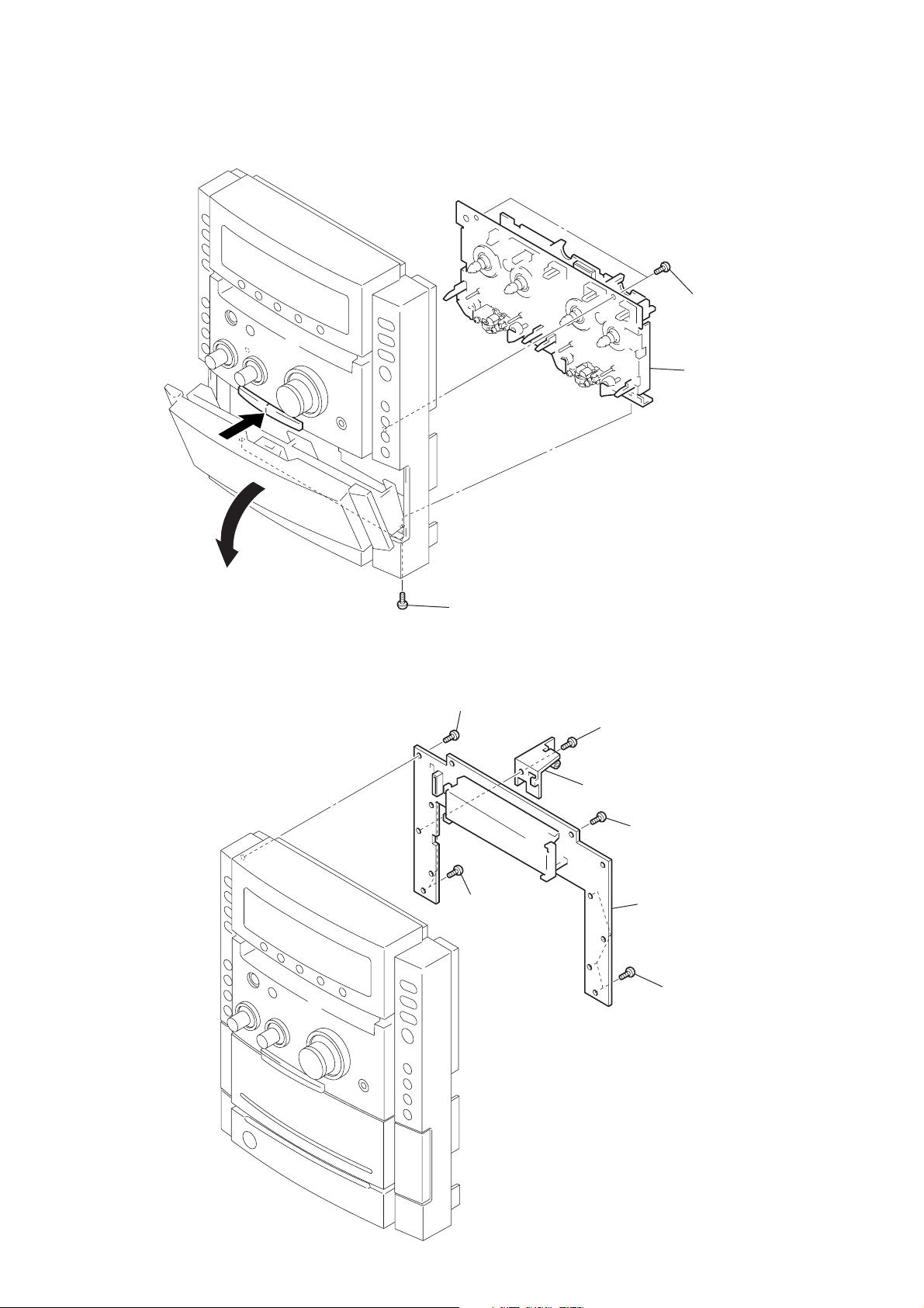
3-4. TAPE MECHANISM DECK
k
1
HCD-CPX22/NXM3
4
two
screws
(+BV (B3))
5
tape mechanism dec
2
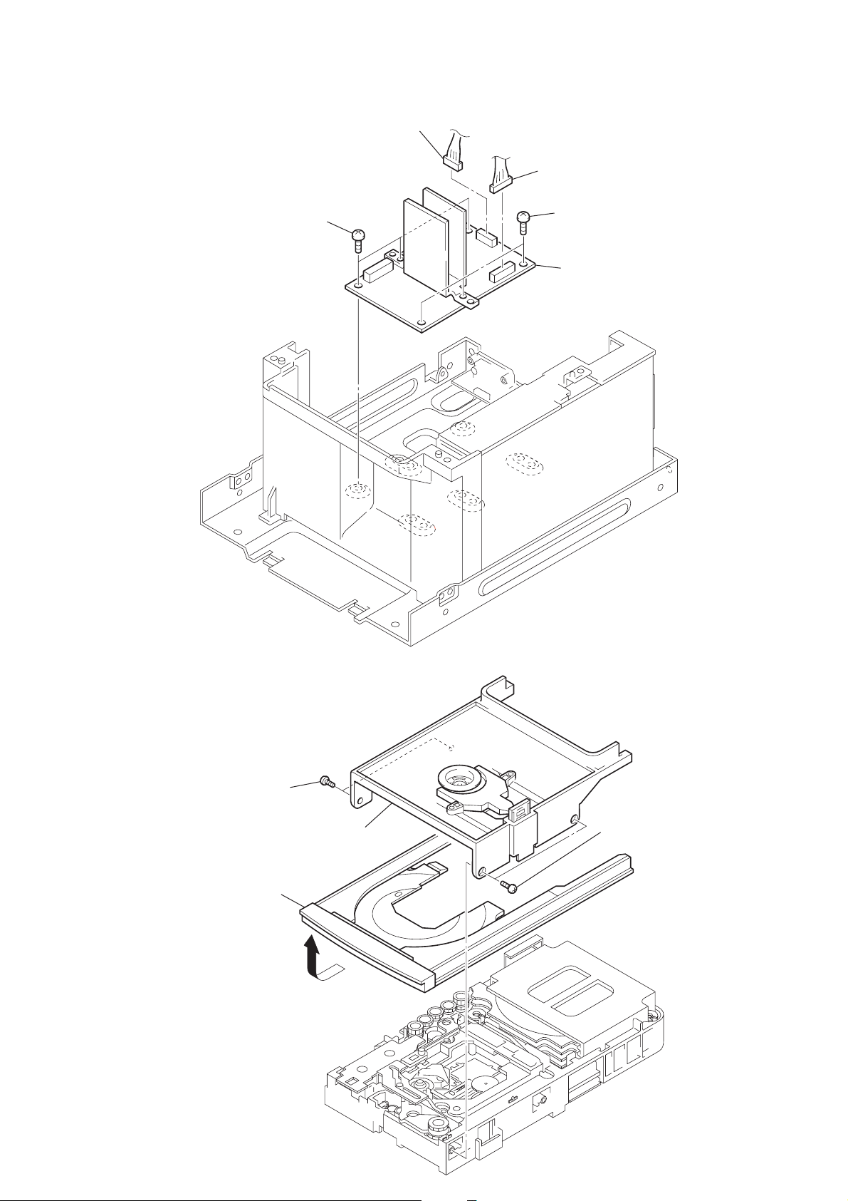
3-5. PANEL BOARD
3
two
screws
(+BV (B3))
5
screw
(+BVTP 2.6X8)
6
three
(+BVTP 2.6X8)
screws
3
screw
(+BVTP 2.6X8)
4
bracket (main)
2
screw
(+BVTP 2.6X8)
7
PANEL board
1
four
screws
(+BVTP 2.6X8)
9
HCD-CPX22/NXM3
)
k
)
3-6. BACK PANEL
4
back panel section
3
two
screws
(+BVTP 2.6X8)
2
two
screws
(+BVTP 3X8
1
screw
(+BVTP 3X8)
3-7. CD MECHANISM DECK (CDM81B-F1BD81A)
2
two
screws
(+BVTP 3X8)
3
bracket
7
screw
(+BVTP 3X8)
5
screw
(+BVTP 3X8)
9
CN701
0
CN201
1
(+BVTP 3X8)
4
two
(+BVTP 3X8)
8
CD mechanism dec
(CDM81B-F1BD81A
screw
screws
10
6
screw
(+BVTP 3X8)
HCD-CPX22/NXM3
3-8. S-MASTER BOARD
4
two
screws
(+BVTP 3X8)
3
connector
(CN702)
1
connector
(CN701)
2
two
screws
(+BVTP 3X8)
5
S-MASTER board
3-9. TRAY
2
two
screws
(+BTP 2.6X8)
5
tray
4
3
bracket
1
two
screws
(+BTP 2.6X8)
11
HCD-CPX22/NXM3
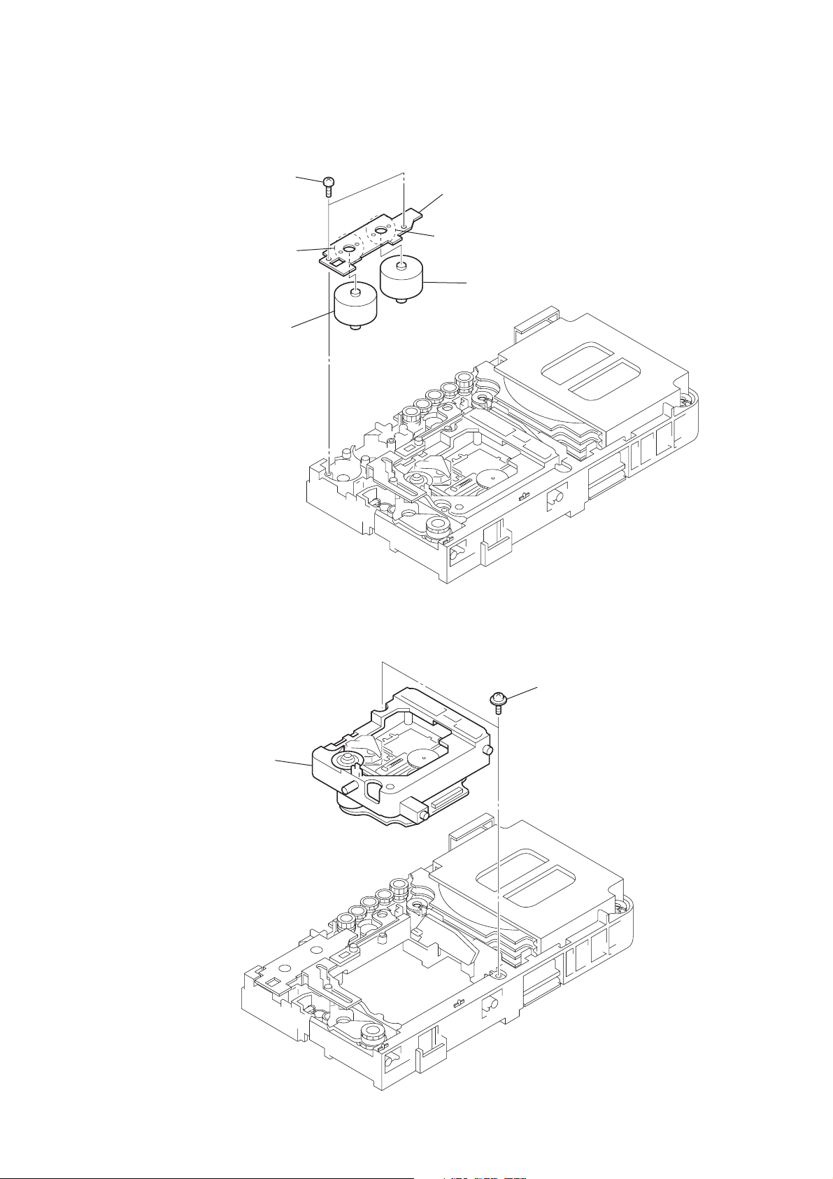
s
3-10. M761 (LD/ST MOTOR), M762 (BU U/D MOTOR)
1
two
screws
(+BTP 2.6X8)
5
Remove soldering from the two points.
6
M762 (BU U/D MOTOR)
2
MOTOR board
3
Remove soldering from the two points.
4
M761 (LD/ST MOTOR)
3-11. BASE UNIT (BU-F1BD81A)
2
base unit (BU-F1BD81A)
1
two floating
(+PTPWH2.6)
screw
12
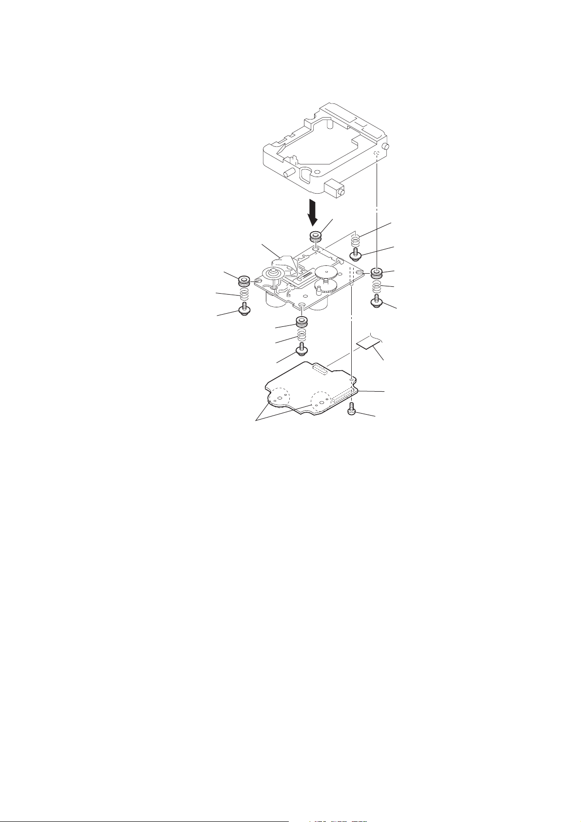
3-12. BD BOARD
w
)
HCD-CPX22/NXM3
qf
optical pick-up
(KSM-215DCP/C2NP)
qs
insulator
qa
coil spring
(insulator)
0
floating
(+PTPWH2.6)
qh
screw
9
insulator
8
coil spring
(insulator)
7
floating
(+PTPWH2.6)
Remove the four solderings of motor.
screw
qd
6
insulator
5
coil spring
(insulator)
4
floating
(+PTPWH2.6)
3
2
(insulator)
1
(+PTPWH2.6
qg
CN101
qk
BD board
qj
screw
(+BVTP 2.6X8)
screw
insulator
coil spring
floating
scre
13
HCD-CPX22/NXM3
SECTION 4
TEST MODE
[Change-over of AM Tuner Step between 9 kHz and 10 kHz]
•A step of AM channels can be changed over between 9 kHz
and 10 kHz.
Procedure:
1. Press
button to turn the set ON.
?/1
2. Select the function “TUNER”, and press [TUNER/BAND]
button to select the BAND “AM”.
3. Press
4. Press x and
button to turn the set OFF.
?/1
buttons simultaneously, and the display
?/1
of fluorescent indicator tube changes to “AM 9 kHz step” or
“AM 10 kHz step”, and thus the channel step is changed over.
[Cold Reset]
• The cold reset clears all data including preset data stored in
the RAM to initial conditions. Execute this mode when
returning the set to the customer.
Procedure:
1.
Press three buttons x , [DIMMER] ,and
?/1
simultaneously.
[Switching MD/VIDEO Functions]
Procedure:
1. Press the
2. Press the
button to turn the set ON.
?/1
button while holding the VIDEO (MD)
?/1
button depressed to toggle between “MD” and “VIDEO.” The
selected mode is displayed.
[Error code indication]
Procedure:
1. Press the
button to turn the set ON.
?/1
2. Select the “CD” function.
3. Press the x , X , and [DISPLAY] buttons simultaneously.
4. The error code is displayed.
5. Press the [TUNING +] button to display the next error code.
Press the[TUNING -] button to display the previous error
code.
[Aging Mode]
This mode can be used for operation check CD section and Tape
deck section.
• If an error occurred:
The aging operation stops and is displayed status.
• If no error occurs:
The aging operation continues repeatedly
1) Error display
Disc error
Display Error
E00D01022 Focus error (No disc)
E00D02022 Sub Q error (Focus is good)
E00D02023 TOC reading error
E00D02014 Access error (Unable within regular time)
Mechanism error
Display Error
E00M__E_0 Error during opening tray
E00M__C_2 EX-CHANGE disc error
E00M__D_0 Error during closing tray
E00M__F_3 EX-OPEN error
E00M__D_5 EX-CLOSE error
E00M__C_2 Chuck-up error
E00M__C_3 Unchucking error
2. Aging mode in Tape Deck section
Procedure:
1. Load the tapes into the decks A and B respectively.
2. Press
button on the set ON
?/1
3. Select the function “TAPE A”
4. Press three buttons x , X , and [TAPE A/B]
simultaneously, and aging mode is started.
5. To exit from the aging mode perform [Cold Reset].
• In the aging mode ,the program is executed in the following
sequence.
Step Operation Display
1 Rewind the TAPE A TAPE A AG-1
2 Rewind the TAPE B TAPE B AG-1
3 Play the TAPE A (t) (2 minute) TAPE A AG-2
4 F•F. (AMS) the TAPE A TAPE A AG-3
5 Play the TAPE A (T) (2 minute) TAPE A AG-4
6 Rewind the TAPE A TAPE A AG-5
7 Play the TAPE B (t) (2 minute) TAPE B AG-2
8 F•F.(AMS) the TAPE B TAPE B AG-3
9 Play the TAPE B (T) (2 minute) TAPE B AG-4
10 Rewind the TAPE B TAPE B AG-5
1. Aging mode in CD section
Procedure:
1. Press
button on the set ON
?/1
2. Select the function “CD”
3. Press three buttons x , X , and [DISC 3] simultaneously.
The “Aging in” display and aging mode is set.
4. Press [DISC 1] button, starts aging mode of all trays check.
5. Press [DISC 2] button ,starts measurement loading time.
6. To exit from the aging mode perform [Cold Reset].
14

HCD-CPX22/NXM3
[GC Test Mode]
• All fluorecent segments and LEDs are tested.
• Microprocessor virsion.
• Keyboard check.
• Display check.
Procedure:
1. To enter the test mode, press the three buttons x , X and
[TUNER/BAND] simultaneously.
2. All segments and LEDs (without STANDBY LED) are turned
on.
3. Press the [TUNING -] button to increment the microprocessor
software version.
4. Press the [TUNING +] button to change the indication for the
microprocessor software version.
3. Press the b B button to set the check mode for the entries
(KEY, JOG, etc.).
4. Press the X button to display the current VACS level.
7. Press the x button to enter the mode to check the display. If
you press this button repeatedly, the display will change
sequentially as the button is pressed.
8. Press the x , X and [TUNER/BAND] buttons simultaneously
to set the standby mode.
[CD Service Mode]
• This mode can run the CD sled motor freely. Use this mode,
for instance, when cleaning the pick-up.
Procedure:
1. Press
button to turn the set ON.
?/1
2. Select the function “CD”.
3. To enter the test mode, press three buttons x , X , and [DISC
1] simultaneously.
4. The CD service mode is selected.The message ‘‘CD SERVICE
MODE’’ is displayed.
5. While holding the [TUNING -] button depressed , to move
the sled to the inside. “SLED IN” is displayed.
While holding the [TUNING +] button depressed, to move
the sled to the outside. “SLED OUT” is displayed.
6. Press the [CD SYNC] button so that “LD ON” and “LD OFF”
are displayed to switch between Laser ON/OFF.
7. To exit from this mode, perform as follows:
1) Move the pick-up to the most inside track.
2) Press
Note: • Always move the pick-up to most inside track when exiting from
this mode. Otherwise, a disc will not be unloaded.
• Do not run the sled motor excessively, otherwise the gear can be
chipped.
button to turn the set OFF.
?/1
[MC Test Mode] (Amplifier SECTION)
• This mode is used to test the function of the amplifier section.
Procedure:
1. Press
2. To enter the test mode, press the three buttons x , X and
button to turn the set ON.
?/1
z/START simultaneously.
3. Turn [VOLUME] knob to counter-clockwise, the function of
the equalizer is set to “MIN”.
4. Turn [VOLUME] knob to clockwise, the function of the
equalizer is set to “MAX”.
5. Whenever turn [BASS] knob to clockwise, the display switches
as follows.
“TONE MAX” t“TONE MIN” t“TONE FLAT”
6. To exit from this mode, press
button to turn the set
?/1
OFF.
[MC Test Mode] (Tape section)
• This mode is used to test the functions of the Tape Procedure.
Procedure:
1. Press
2. To enter the test mode, press the three buttons x , X and
z/START simultaneously.
button to turn the set ON.
?/1
3. While holding the [DIMMER] button depressed, turn the ALC
ON.
4. Press the z/START button to start REC (recording).
5. While recording, press the [TUNING +] button to perform
automatic rewind and automatic playback (for FF version).
Also, press the [TUNING -] button to perform automatic rewind
and automatic playback (for FR version).
6. Select the function “TAPE A” or “TAPE B”
7. Press the [CD-SYNC] button while “TAPE A” or “TAPE B”
is selected, to perform AMS check. “EDG[ ]” is displayed.
A number appears inside[ ].
8. To exit from this mode, press
button to turn the set
?/1
OFF.
[CD Ship Mode (LOCK) ]
• This mode moves the pick-up to the position durable to
vibration. Use this mode when returning the set to the customer
after repair.
Procedure:
1. Press
button to turn the set ON.
?/1
2. Select the function “CD”.
3. Press x button and [CD] button simultaneously.
4. The “STANDBY” display blinks instantaneously, and the CD
ship mode is set.
5. To fluorescent indicator tube displays ‘‘LOCK’’.
[CD Ship (LOCK) & COLD RESET MODE]
Procedure:
1. Press
button to turn the set ON.
?/1
2. Select the function “CD”.
3.
Press three buttons x , X and VIDEO (MD) simultaneously.
4. The “STANDBY” display blinks instantaneously and CD ship
mode is set.
5. To fluorescent indicator tube displays “LOCK” and the set is
reset.
[CD power -manage function]
Procedure:
1. Press
button to the set ON
?/1
2. Select the function “CD”.
3. Press
4. Press x and
button to turn the set OFF.
?/1
?/1
buttons simultaneously ,and the display
of fluorescent indicator tube changes “CD POWER OFF” or
“CD POWER ON”.
5. Press
button to turn the set OFF.
?/1
15

HCD-CPX22/NXM3
[DISC Tray Lock]
Procedure:
1. Press
2. Select the function “CD”.
3. Press x and CD Z buttons simultaneously for 5 seconds.
And the displays of fluorescent indicator tube changes to
“LOCKED” or “UNIOCKED”.
4. Press
[CD Repeat 5 Times Limit Release Mode]
Procedure:
1. Press
2. Select the function “CD”.
3. Press three buttons x , X and [CD SYNC] simultaneously.
4. The message “LIMIT OFF” is displayed.
5. Press
[AMP TEST MODE]
Procedure:
1. Press
2. To enter the test mode, press three buttons x , X and [DSGX]
simultaneously.
3. Display will changes ‘‘VACS ON’’ to ‘‘VACS OFF’’.
4. Press
button to the set ON.
?/1
button to turn the set OFF.
?/1
button to turn the set ON.
?/1
button the set OFF.
?/1
button to turn the set ON.
?/1
button to turn the set OFF.
?/1
16
HCD-CPX22/NXM3
SECTION 5
MECHANICAL ADJUSTMENTS
Precaution
1. Clean the following parts with a denatured alcohol-moistened
swab:
record/playback heads pinch rollers
erase head rubber belts
capstan idlers
2. Demagnetize the record/playback head with a head
demagnetizer.
3. Do not use a magnetized screwdriver for the adjustments.
4. After the adjustments, apply suitable locking compound to
the parts adjusted.
5. The adjustments should be performed with the rated power
supply voltage unless otherwise noted.
Torque Measurement
Mode Torque meter Meter reading
3.06 N • m to 6.96 N • m
FWD CQ-102C 31 to 71 g • cm
(0.43 – 0.98 oz • inch)
FWD
back tension
REV CQ-102RC 31 to 71 g • cm
REV
back tension
FF/REW CQ-201B 71 to 143 g • cm
FWD tension CQ-403A 100 g or more
REV tension CQ-403R 100 g or more
CQ-102C 2 to 6 g • cm
CQ-102RC 2 to 6 g • cm
0.19 N • m to 0.58 N • m
(0.02 – 0.08 oz • inch)
3.06 N • m to 6.96 N • m
(0.43 – 0.98 oz • inch)
0.19 N • m to 0.58 N • m
(0.02 – 0.08 oz • inch)
6.96 N • m to 14.02 N • m
(0.98 – 1.99 oz • inch)
9.80 N • m
(3.53 oz or more)
9.80 N • m
(3.53 oz or more)
SECTION 6
ELECTRICAL ADJUSTMENTS
DECK SECTION
1. Demagnetize the record/playback head with a head
demagnetizer.
2. Do not use a magnetized screwdriver for the adjustments.
3. After the adjustments, apply suitable locking compound to the
parts adjust.
4. The adjustments should be performed with the rated power
supply voltage unless otherwise noted.
5. The adjustments should be performed in the order given in
this service manual. (As a general rule, playback circuit
adjustment should be completed before performing recording
circuit adjustment.)
6. The adjustments should be performed for both L-CH and RCH.
7. Switches and controls should be set as follows unless otherwise
specified.
•Test Tape
Tape Signal Used for
P-4-A100 10 kHz, –10 dB Azimuth Adjustment
RECORD/PLAYBACK HEAD AZIMUTH ADJUST-MENT
DECK A DECK B
Note: Perform this adjustments for both decks
Procedure:
1. Mode: Playback
test tape
P-4-A100
(10 kHz, –10 dB)
0 dB=0.775 V
MAIN board
CN304
Pin
1
(L-CH)
3
(R-CH)
Pin
set
MAIN board
CN304
2
(GND)
Pin
level meter
+
–
17
HCD-CPX22/NXM3
e
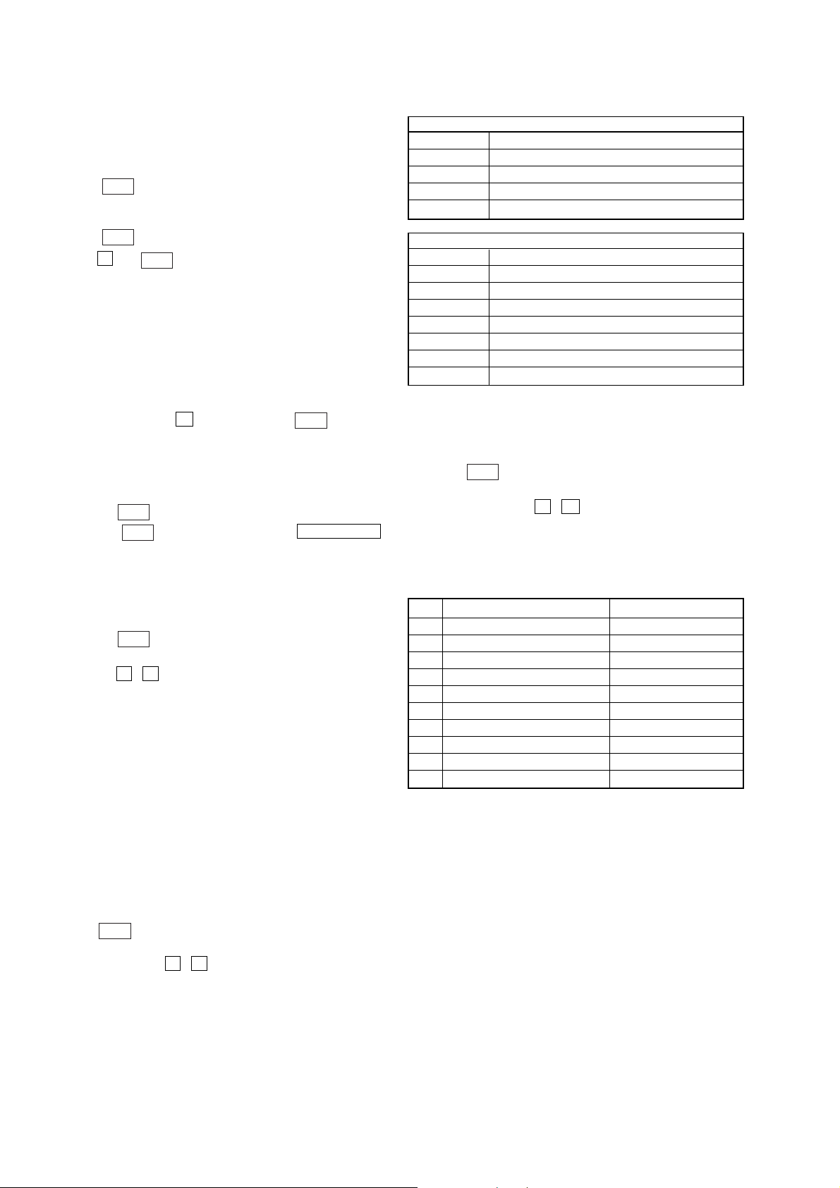
2. Turn the adjustment screw and check output peaks. If the peaks
do not match for L-CH and R-CH, turn the adjustment screw
so that outputs match within 1dB of peak.
Output
level
within
1dB
L-CH
peak
R-CH
peak
within
1dB
Screw
position
L-CH
peak
Screw
position
R-CH
peak
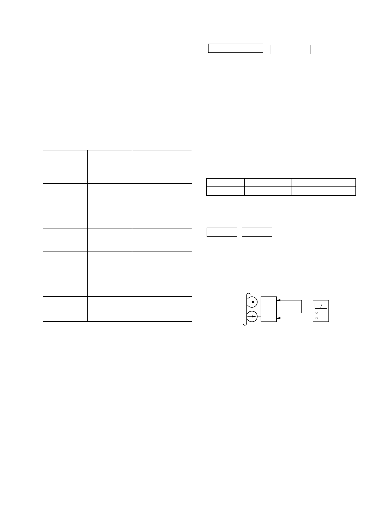
3. Mode: Playback
test tape
P-4-A100
(10 kHz, –10 dB)
L-CH
MAIN
board
CN301
set
R-CH
waveform of oscilloscope
pin
L
R
pin
1
pin
3
2
oscilloscop
H
V
CD SECTION
Note:
1. CD Block is basically designed to operate without adjustment.
Therefore, check each item in order given.
2. Use YEDS-18 disc (3-702-101-01) unless otherwise indicated.
3. Use an oscilloscope with more than 10MW impedance.
4. Clean the object lens by an applicator with neutral detergent
when the signal level is low than specified value with the
following checks.
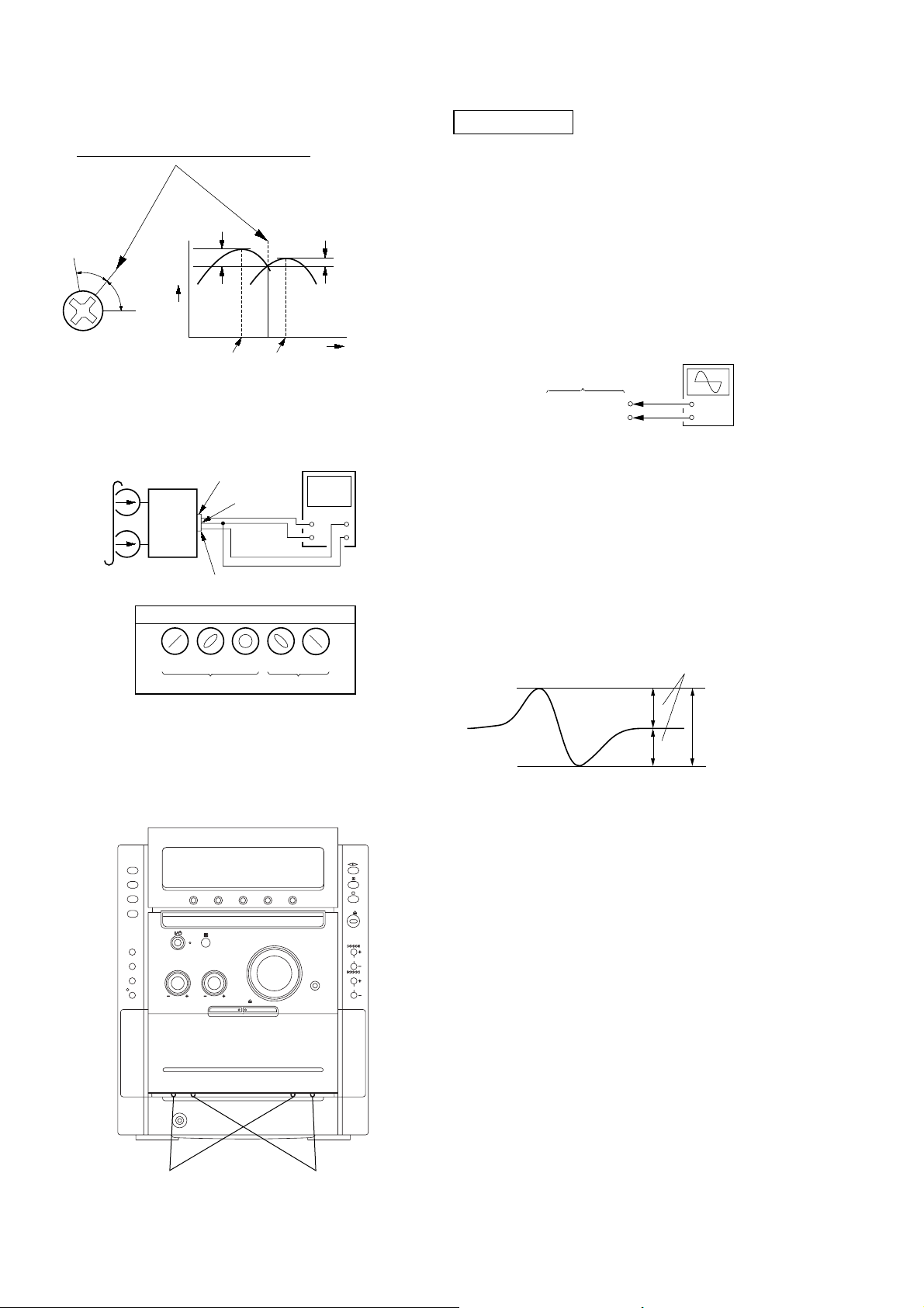
S-curve Check
Connection:
oscilloscope
CD board
TPO102 (FE1)
TP117 (VC)
Procedure:
1. Connect an oscilloscope to test point TPO102 (FE1) and TP
117(VC) on the CD board.
2. Turn the power on.
3. Put the disc (YEDS-18) in and turned power switch on again
and actuate the focus search. (actuate the focus search when
disc table is moving in and out)
4. Check the oscilloscope waveform (S-curve) is symmetrical
between A and B. And confirm peak to peak level within 2.4
± 1 Vp-p.
+
–
in phase 45°90°135°180
good
°
wrong
4. After the adjustments, apply suitable locking compound to
the pats adjusted.
Adjustment Location: Playback Head (Deck A).
Record/Playback/Erase Head (Deck B).
S-curve waveform
symmetry
A
within 2.4
B
Note:
•Try to measure several times to make sure than the ratio
of A : B or B : A is more than 10 : 7.
•Take sweep time as long as possible and light up the
brightness to obtain best waveform.
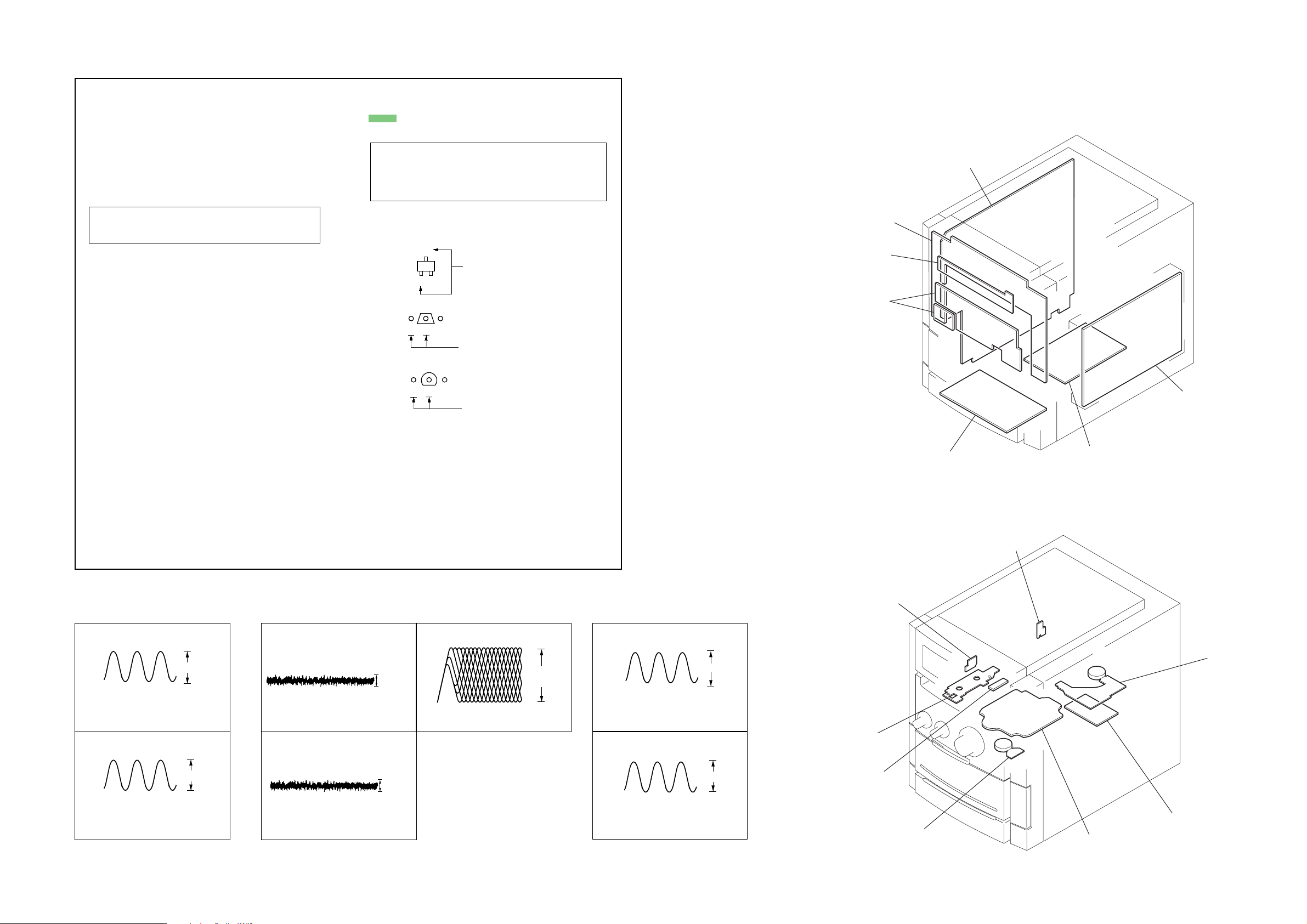
Checking Location: CD board (SIDE B)
(See page 20.)
±
1 Vp-p
18
reverse
forward
HCD-CPX22/NXM3
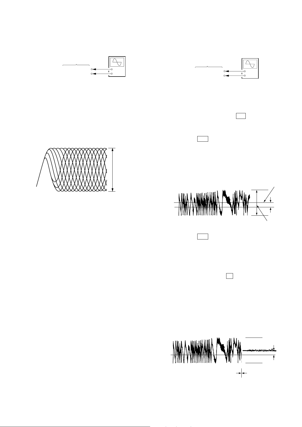
RFAC Level Check
Connection:
oscilloscope
CD board
TP124 (RFAC)
TP117 (VC)
+
–
Procedure:
1. Connect an oscilloscope to test point TP124 (RFAC) and TP
117(VC) on the CD board.
2. Turn the power on.
3. Put the disc (YEDS-18) in to playback the number five track.
4. Confirm that oscilloscope waveform is clear and check RFAC
signal level is correct or not.
Note: A clear RFAC signal waveform means that the shape “◊” can be
RFAC signal waveform
clearly distinguished at the center of the waveform.
VOLT/DIV: 200 mV
TIME/DIV: 500 ns
level: 0.9 ± 0.4 Vp-p
E-F Balance Check
Connection:
oscilloscope
CD board
TPO103 (TE1)
TP117 (VC)
+
–
Procedure:
1. Connect an oscilloscpe to test point TPO103 (TE1) and TP117
(VC) on the CD board.
2. Turn the power on.
3. Select the function “CD”.
4. Press three buttons of [ENTER], M , and
[SURRUUND MODE] simultaneously to set the CD service
mode.
5. Put the disc (YEDS-18) in to playback the number five track.
6. Press the . button. The message “TRAVERSE” is
displayed. (The tracking servo and the sledding servo are
turned OFF)
7. Check the level B of the oscilliscope's waveform and the A
(DC voltage) of the center of the Traverse waveform.
Confirm the following :
A/B x 100 = less than ± 22%
Tr averse Waveform
Center of
the waveform
Checking Location: CD board (SIDE B)
(See page 20.)
B
0V
level: 1.0 ± 0.5 Vp-p
8. Press the . button. The message “TRAVERSE” is
A (DC
voltage)
displayed. (The tracking servo and sledding servo are turned
ON)
Confirm the C (DC voltage) is almost equal to the A (DC
voltage) is step 5.
9. To exit from this mode, perform as follows.
1) Move the optical pick-up to the most inside track.
2) Press three buttons of x , [CLEAR], and [DISPLAY]
simultaneously. (cold reset)
Notes:
• Always move the optical pick-up to most inside track
when exiting from this mode. Otherwise, a disc will not
be unloaded.
• Do not run the sled motor excessively, otherwise the gear
can be chipped.
Tr averse Waveform
0V
Tr acking servo
Sled servo
OFF
Tr acking servo
Sled servo
ON
Checking Location: CD board (SIDE B) (See page 20.)
C (DC
voltage)
19
HCD-CPX22/NXM3
Checking Location:
– CD BOARD (SIDE B) –
TP117 (VC)
JPO103 (TE1)
JPO102 (FE1)
IC101
TP124 (RFAC)
20
49.152MHz
4Vp-p
p
SECTION 7
MAIN board
PANEL board
DISC SW board
VOL board
HP board
S-MASTER board
switching regulator
SW(2) board
SW(1) board
MOTOR board
SENSOR board
ENCODER board
BD board
RELAY board
SP OUT board
DIAGRAMS
HCD-CPX22/NXM3
For schematic diagrams.
Note:
• All capacitors are in µF unless otherwise noted. (p: pF)
50 WV or less are not indicated except for electrolytics
and tantalums.
• All resistors are in Ω and 1/
specified.
•%: indicates tolerance.
• f : internal component.
• 2 : nonflammable resistor.
• 5 : fusible resistor.
Note: The components identified by mark 0 or dotted line
with mark ! are critical for safety.
Replace only with part number specified.
• C : panel designation.
• A : B+ Line.
• B : B– Line.
• H : adjustment for repair.
•Voltages and waveforms are dc with respect to ground
under no-signal conditions.
no mark: TUNER (FM/AM)
( ): CD PLAY
< >: TAPE PLAY
[ ]: TAPE REC
* : Impossible to measure
•Voltages are taken with a VOM (Input impedance 10 MΩ).
Voltage variations may be noted due to normal production tolerances.
•Waveforms are taken with a oscilloscope.
Voltage variations may be noted due to normal production tolerances.
• Signal path.
F : TUNER (FM/AM)
E : TAPE PLAY (DECK A)
d : TAPE PLAY (DECK B)
G : RECORD
J : CD PLAY (ANALOG OUT)
c : CD PLAY (DIGITAL OUT)
4
W or less unless otherwise
Note on Printed Wiring Boards:
Note:
• X : parts extracted from the component side.
• : Pattern from the side which enables seeing.
(The other layers' patterns are not indicated.)
Caution:
Parts face side: Parts on the parts face side seen from
(Side A) the parts face are indicated.
Pattern face side: Parts on the pattern face side seen from
(Side B) the pattern face are indicated.
• Indication of transistor.
C
Q
B
E
Q
B
CE
Q
B
CE
• Abbreviation
E3 : 240V AC Area in E model
E51 : Chilean and Peruvian model
EA : Saudi Arabia mdoel
RU : Russian model
These are omitted.
These are omitted.
These are omitted.
7-1. CIRCUIT BOARD LOCATION
• Abbreviation
E3 : 240V AC Area in E model
E51 : Chilean and Peruvian model
EA : Saudi Arabia mdoel
RU : Russian model
•WAVEFORMS
– MAIN BOARD –
IC401 0 XC-IN
1
32.768KHz
IC401 qg X-IN
2
16MHz
1.5Vp-p
VOL/DIV : 0.5 V AC
TIME/DIV : 2.0 µsec
1.5Vp-p
VOL/DIV : 0.5 V AC
TIME/DIV : 50 nsec
– BD BOARD –
IC101 wa TEI
1
IC101 wd FEI
2
0.15Vp-p
VOL/DIV : 0.2 V AC
TIME/DIV : 0.2 msec
VOL/DIV : 0.1 V AC
TIME/DIV : 1 msec
0.4Vp-
IC101 ra RFACO
3
0.96Vp-p
VOL/DIV : 0.2 V AC
TIME/DIV : 0.5 µsec
– S-MASTER BOARD –
IC705 rk XFSOIN
1
VOL/DIV : 2 V AC
TIME/DIV : 20 nsec
IC703 6
2
12.288 MHz
VOL/DIV : 1 V AC
TIME/DIV : 50 nsec
2Vp-p
HCD-CPX22/NXM3
2121
 Loading...