

Sony HCDMD-1-EX Service manual
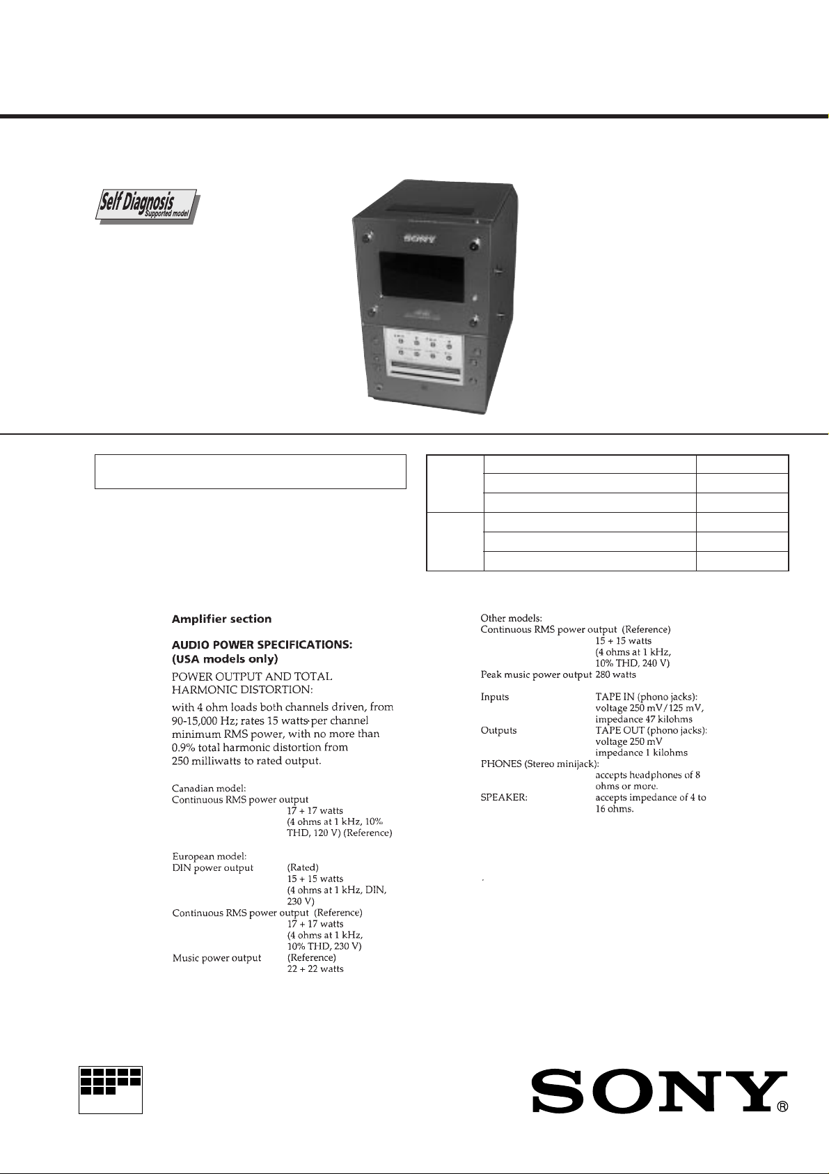
HCD-MD1EX
SERVICE MANUAL
HCD-MD1EX is the Amplifier, CD play er ,
Mini disc Deck and Tuner section in
CMT-MD1.
U.S. and foreign patents licensed form Dolby Laboratories
Licensing Corporation.
Section
Section
CD
MD
US Model
Canadian Model
AEP Model
UK Model
E Model
Model Name Using Similar Mechanism HCD-MD333
Base Unit Name BU-22BD19
Optical Pick-up Name KSS-213B/K-N
Model Name Using Similar Mechanism HCD-MD333
Mechanism Name MDM-3J
Optical Pick-up Name KMS-260A/J1N
SPECIFICATIONS
– Continued on next page –
MICROFILM
COMPACT Hi-Fi COMPONENT SYSTEM
– 2 –
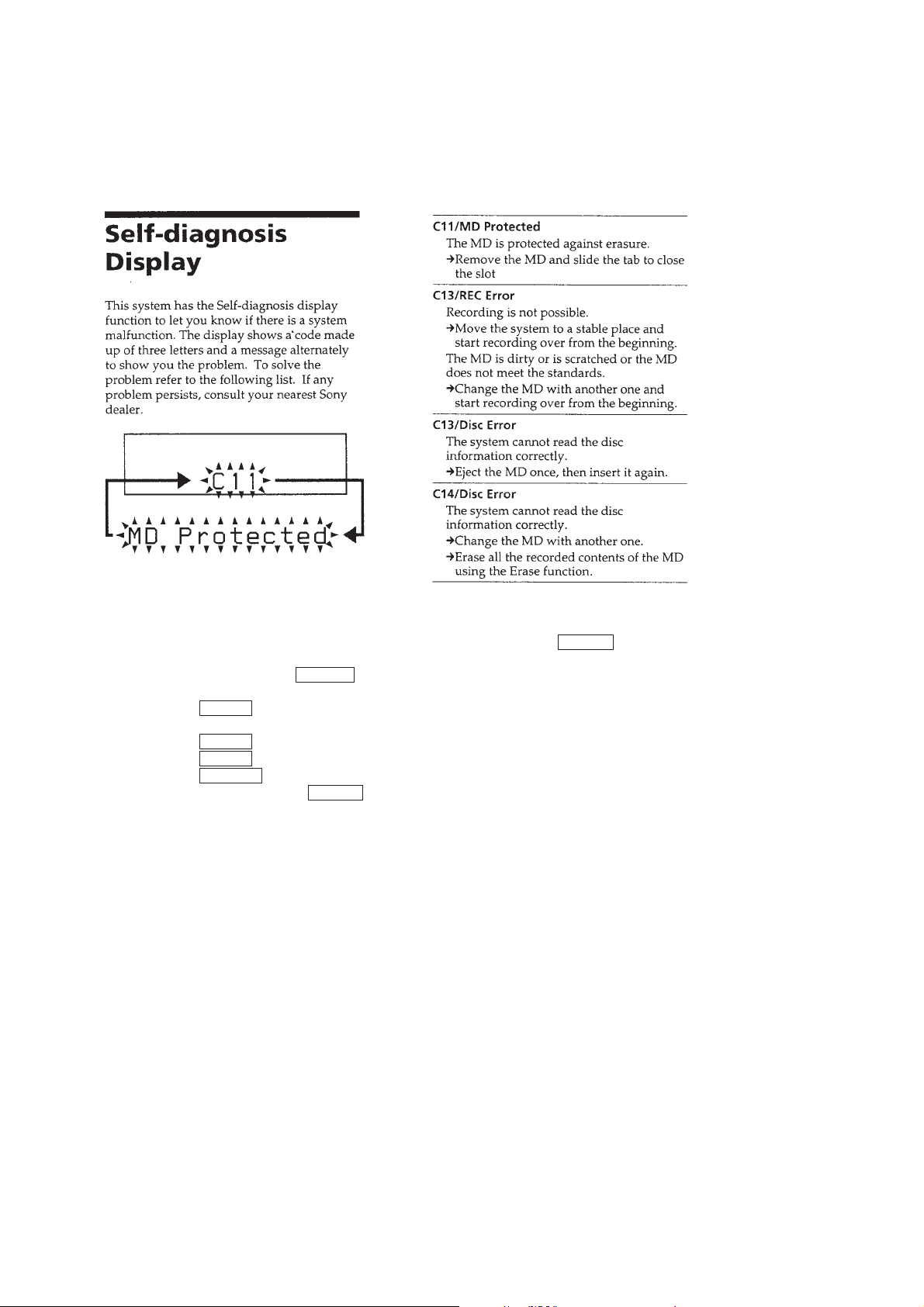
SELF-DIAGNOSIS FUNCTION
The self-diagnosis function consists of error codes for users which are displayed automatically when errors occur, and error codes which
show the error history in the test mode during servicing. For details on how to vie w err or codes for users, refer to the follo wing box in the
instruction manual. For details on how to perform checks during servicing, refer to the following “Procedure for Using the Self -Diagnosis
Function (Error History Display Mode)”.
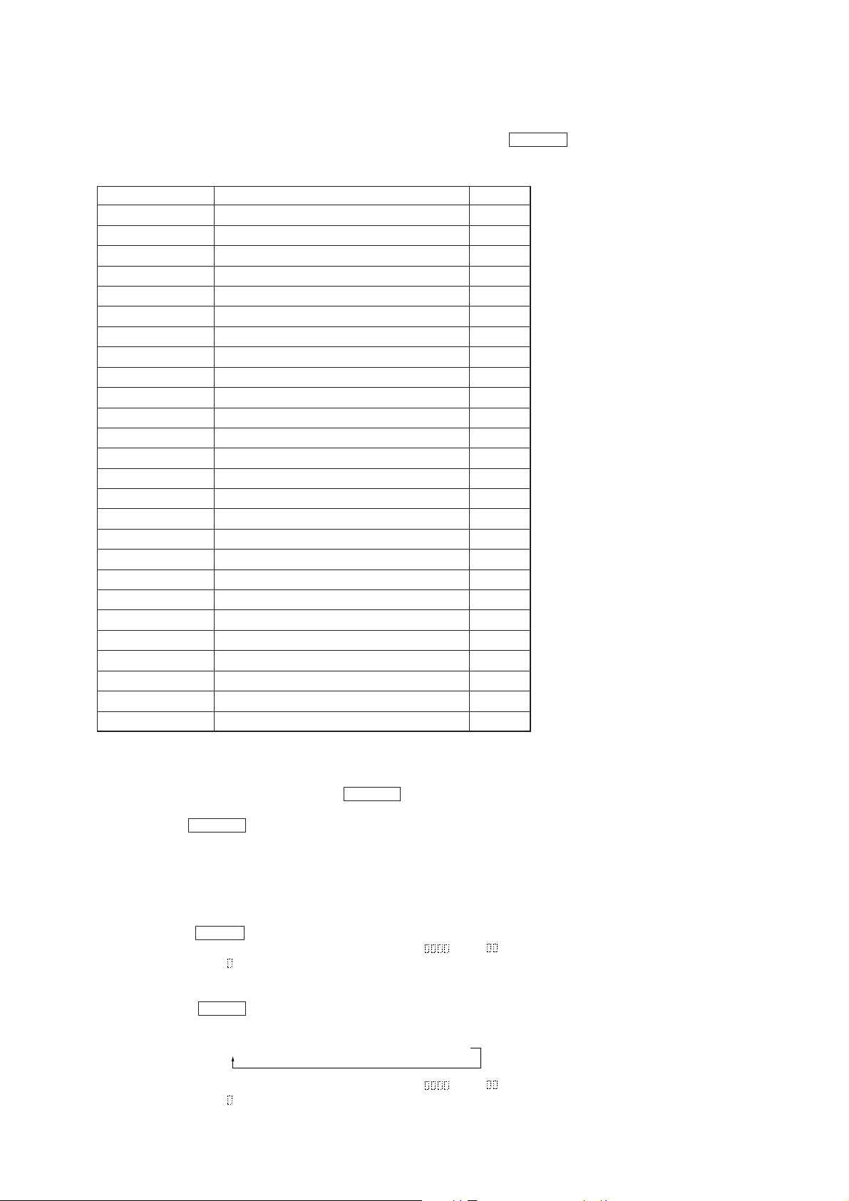
Procedure for Using the Self-Diagnosis Function (Error History Display Mode)
Note: Perform the self-diagnosis function in the “error history display mode” in the test mode. The following describes the least required steps. Be careful
not to enter other modes by mistake. If other modes are set accidentally, press the ^ (CD) button to exit that mode.
1. With the power off, press the =0 button while pressing the [VOLUME–] button.
2. Press the [VOLUME+/–] button to display “ERR DP MODE”.
3. Pressing the p (CD) button sets the error history mode and displays “total rec”.
4. Select the contents to be displayed or executed with pressing the [VOLUME+/–] button.
5. Pressing the 6 (CD) button displays or executes the contents selected.
6. Pressing the 6 (CD) button another time returns to step 4.
7. Pressing the ^ (CD) button displays “ERR DP MODE” and exits the error history mode.
8. To exit the test mode, press the p (MD) button while pressing the [FUNCTION] button.
The unit sets into the STANDBY state, and the test mode ends.
– 3 –
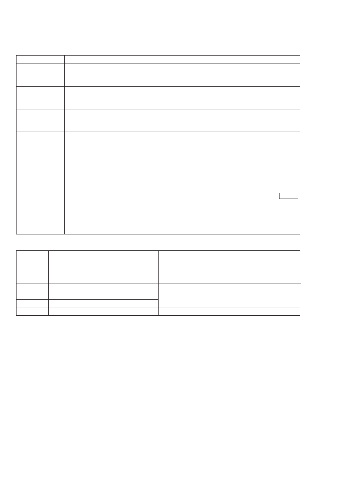
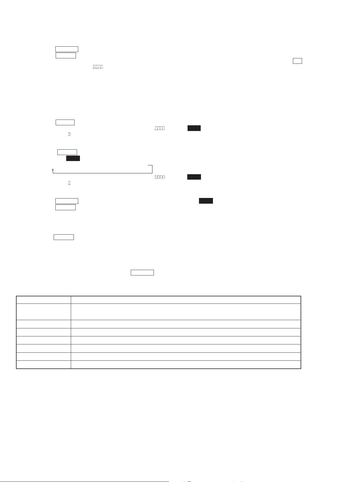
ITEM OF ERROR HISTORY MODE ITEMS AND CONTENTS
Selecting the Test Mode
Display
total rec
total play
retry err
total err
err history
er refresh?
Details of History
Displays the recording time in the form of “rππππππh”.
The displayed time is the total number of hours the laser is high power, which is about one-fourth of the actual
recording time. The time is displayed in decimal digits between 0h to 65535h.
Displays the playback time in the form of “pππππππh”.
The displayed time is the total actual play time. The paused time is not counted. The time is displayed in
decimal digits between 0h to 65535h.
Displays the total number of retries during recording and retry errors during playback in the form of “rππpππ”.
“r” indicates the retries during recording while “p” indicates the retry errors during playback. The number of
retries is displayed in hexadecimal digits between 00 to FF.
Displays the total number of errors in the form of “total ππ”.
The number of errors is displayed in hexadecimal digits between 00 to FF.
Displays the 10 latest errors in the form of “0π E@@”.
The π indicates the history number. The smaller the number, the newer is the error. (00 is the latest error.)
The @@ indicates the error code. Refer to the following table for details. Press the
switch the error history.
Mode which erases all the error histories.
The error history serves as a reference for when to replace the optical pick-up. Perform this procedure when the
optical pick-up has been replaced in order to erase past error histories and not at other times. Press the p (CD)
button when “er refresh??” is displayed. The history will be erased and “Complete!” will be displayed momentarily. Be sure to check the following when this mode has been executed.
• Check that the data has been erased.
• Perform recording and playback, and check that the mechanism operates normally.
[VOLUME+/–] button to
Table of Error Codes
Error Code
E00
E01
E02
E03
E04
No error
Disc error. Cannot read PTOC
(Disc is ejected out)
Disc error. UTOC error
(Disc is not ejected out)
Loading error
Cannot read address (Servo has deviated)
Details of Error
Error Code
E05
E06
E07
E08
E09
E0A
Details of Error
FOK has deviated
Unfocused (Servo has deviated)
Recording retry
Recording retry error
Play retry error
(Access error)
Playback retry error (C2 error)
– 4 –

TABLE OF CONTENTS
SELF-DIAGNOSIS FUNCTION ................................... 3
1. SERVICING NOTES .............................................. 6
2. GENERAL .................................................................. 9
3. DISASSEMBLY ......................................................... 12
4. SERVICE MODE...................................................... 19
5. TEST MODE.............................................................. 20
6. ELECTRICAL ADJUSTMENTS
MD Section ..................................................................... 26
CD Section ...................................................................... 31
7. DIAGRAMS
7-1. Block Diagram – CD Section – ..................................... 33
7-2. Block Diagram – MD Section – .................................... 35
7-3. Block Diagram – MAIN Section – ................................ 37
7-4. Block Diagram
– DISPLAY/POWER SUPPLY Section – ..................... 39
7-5 Note for Printed Wiring Boards and
Schematic Diagrams ....................................................... 42
7-6. Pr inted Wiring Board – BD (CD) Section –.................. 43
7-7. Schematic Diagram – BD (CD) Section – ...................... 45
7-8. Pr inted Wiring Board – BD (MD) Section –................. 47
7-9. Schematic Diagram – BD (MD) Section (1/3) – ............ 49
7-10. Schematic Diagram – BD (MD) Section (2/3) – ............ 51
7-11. Schematic Diagram – BD (MD) Section (3/3) – ............ 53
7-12. Printed Wiring Board – MAIN Board (side A) – .......... 55
7-13. Printed Wiring Board – MAIN Board (side B) – .......... 57
7-14. Schematic Diagram – MAIN Section (1/2) – ................ 59
7-15. Schematic Diagram – MAIN Section (2/2) – ................ 61
7-16. Printed Wiring Boards – PANEL Section – .................. 63
7-17. Schematic Diagram – PANEL Section –........................ 65
7-18. Printed Wiring Boards
– AMP/TRANSFORMER Section – .............................. 67
7-19. Schematic Diagram
– AMP/TRANSFORMER Section – .............................. 69
7-20. Printed Wiring Board – POWER Section –................... 71
7-21. Schematic Diagram – POWER Section – ...................... 73
7-22. Printed Wiring Boards – MOTOR/SW Section – ......... 75
7-23. Schematic Diagram – MOTOR/SW Section – ............... 76
7-24. IC Pin Function Description ........................................... 86
8. EXPLODED VIEWS................................................ 96
9. ELECTRICAL PARTS LIST ............................. 103
– 5 –

SECTION 1
SERVICING NOTES
Flexible Circuit Board Repairing
• Keep the temperature of the soldering iron around 270 ˚C during repairing.
• Do not touch the soldering iron on the same conductor of the
circuit board (within 3 times).
• Be careful not to apply force on the conductor when soldering
or unsoldering.
Notes on chip component replacement
• Never reuse a disconnected chip component.
• Notice that the minus side of a tantalum capacitor may be damaged by heat.
CAUTION
Danger of explosion if battery is incorrectly replaced.
Replace only with the same or equivalent type recommended by
the manufacturer.
Discard used batteries according to the manufacturer’ s instructions.
ADVARSEL!
Lithiumbatteri-Eksplosionsfare ved fejlagtig håndtering.
Udskiftning må kun ske med batteri
af samme fabrikat og type.
Levér det brugte batteri tilbage til leverandøren.
ADVARSEL
Eksplosjonsfare ved feilaktig skifte av batteri.
Benytt samme batteritype eller en tilsvarende type
anbefalt av apparatfabrikanten.
Brukte batterier kasseres i henhold til fabrikantens
instruksjoner.
VARNING
Explosionsfara vid felaktigt batteribyte.
Använd samma batterityp eller en likvärdig typ som
rekommenderas av apparattillverkaren.
Kassera använt batteri enligt gällande föreskrifter.
VAROITUS
Paristo voi räjähtää, jos se on virheellisesti asennettu.
V aihda paristo ainoastaan laite valmistajan suosittelemaan tyyppiin.
Hävitä käytetty paristo valmistajan ohjeiden mukaisesti.
NOTES ON HANDLING THE OPTICAL PICK-UP
BLOCK OR BASE UNIT
The laser diode in the optical pick-up block may suffer electrostatic break-down because of the potential difference generated
by the charged electrostatic load, etc. on clothing and the human
body.
During repair, pay attention to electrostatic break-down and also
use the procedure in the printed matter which is included in the
repair parts.
The flexible board is easily damaged and should be handled with
care.
NOTES ON LASER DIODE EMISSION CHECK
The laser beam on this model is concentrated so as to be focused
on the disc reflective surface by the objective lens in the optical
pick-up block. Therefore, when checking the laser diode emission, observe from more than 30 cm away from the objectiv e lens.
LASER DIODE AND FOCUS SEARCH OPERATION
CHECK
Carry out the “S curve check” in “CD section adjustment” and
check that the S curve waveforms is output three times.
Notes on chip component replacement
• Never reuse a disconnected chip component.
• Notice that the minus side of a tantalum capacitor may be damaged by heat.
Flexible Circuit Board Repairing
• Keep the temperature of the soldering iron around 270 ˚C during repairing.
• Do not touch the soldering iron on the same conductor of the
circuit board (within 3 times).
• Be careful not to apply force on the conductor when soldering
or unsoldering.
Note:
Be sure to connect all wires (including FFC) in the MD
section before applying power or ICs ma y be damaged.
SAFETY-RELATED COMPONENT WARNING!!
COMPONENTS IDENTIFIED BY A ! MARK ON THE SCHEMATIC
DIAGRAMS, EXPLODED VIEWS AND IN THE PARTS LIST ARE
CRITICAL TO SAFE OPERATION. REPLACE THESE COMPONENTS WITH SONY PARTS WHOSE PART NUMBERS APPEAR
AS SHOWN IN THIS MANUAL OR IN SUPPLEMENTS PUBLISHED BY SONY.
ATTENTION AUX COMPOSANTS RELATIFS ÀLA
SÉCURITÉ!
LES COMPOSANTS IDENTIFÉS P AR UNE MARQUE ! SUR LES
SCHÉMAS DE PRINCIPE, LES VUES EXPLOSÉES ET LES
LISTES DE PIECES
SONT D'UNE IMPORT ANCE CRITIQUE POUR LA SÉCURITÉ DU
FONCTIONNEMENT. NE LES REMPLACER QUE PAR DES
COMPOSANTS SONY DONT LE NUMÉRO DE PIÉCE EST
INDIQUÉ DANS LE PRÉSENT MANUEL OU DANS LES
SUPPLÉMENTS PUBLIÉS PAR SONY.
– 6 –
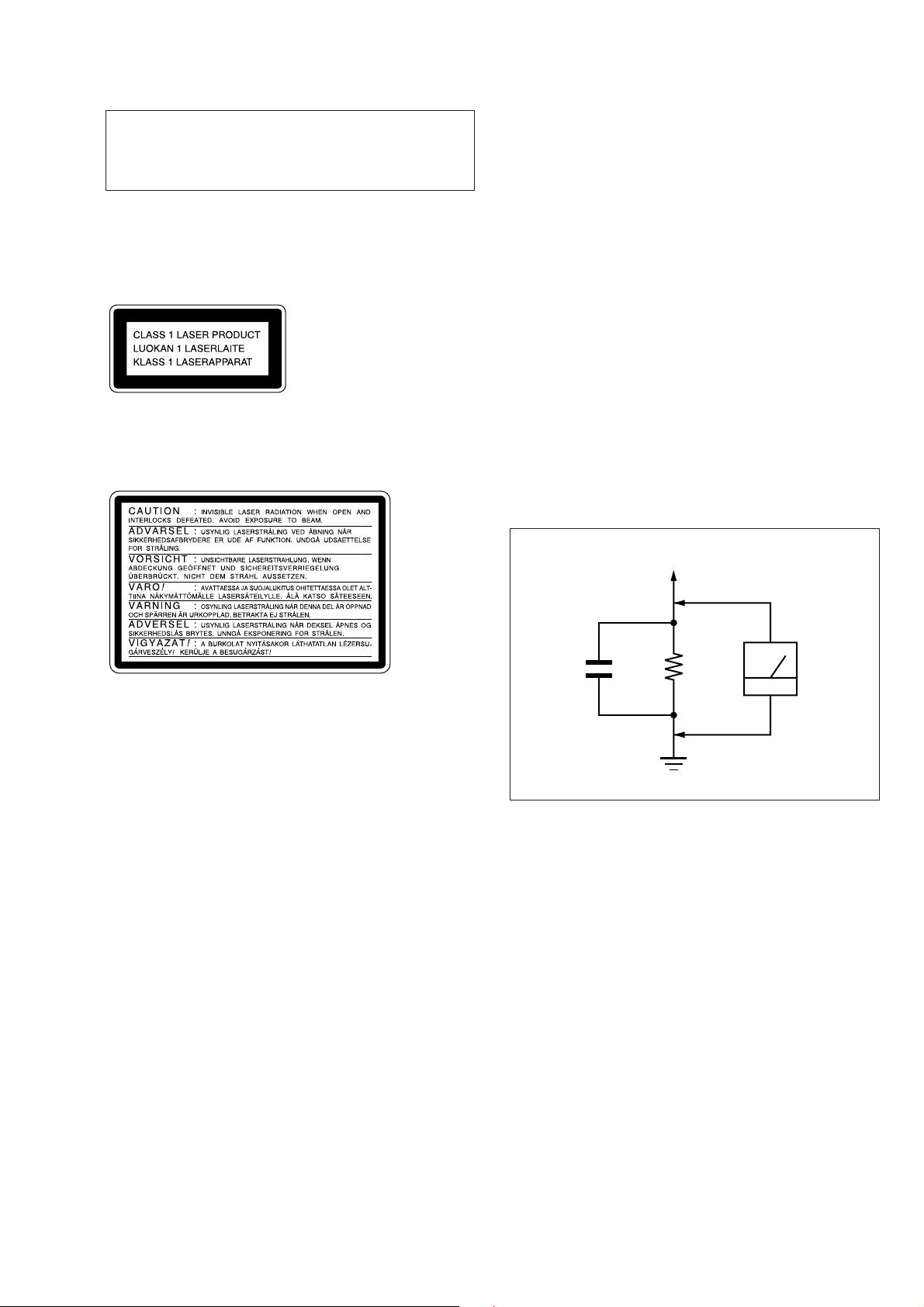
CAUTION
Use of controls or adjustments or performance of procedures
other than those specified herein may result in hazardous radiation exposure.
This appliance is classified as a CLASS 1 LASER product.
The CLASS 1 LASER PRODUCT MARKING is located on
the rear exterior.
Laser component in this product is capable of emitting radiation
exceeding the limit for Class 1.
The following caution label is located inside the unit.
SAFETY CHECK-OUT
After correcting the original service problem, perform the following safety check before releasing the set to the customer:
Check the antenna terminals, metal trim, “metallized” knobs,
screws, and all other exposed metal parts for AC leakage.
Check leakage as described below.
LEAKAGE TEST
The AC leakage from any exposed metal part to earth ground and
from all exposed metal parts to any exposed metal part having a
return to chassis, must not exceed 0.5 mA (500 microampers.).
Leakage current can be measured by any one of three methods.
1. A commercial leakage tester, such as the Simpson 229 or RCA
WT -540A. Follow the man ufacturers’ instructions to use these
instruments.
2. A battery-operated AC milliammeter. The Data Precision 245
digital multimeter is suitable for this job.
3. Measuring the voltage drop across a resistor by means of a
VOM or battery-operated AC voltmeter. The “limit” indication is 0.75 V, so analog meters must have an accurate lowvoltage scale. The Simpson 250 and Sanwa SH-63Tr d are e xamples of a passive VOM that is suitable. Nearly all battery
operated digital multimeters that have a 2 V AC range are suitable. (See Fig. A)
To Exposed Metal
Parts on Set
AC
1.5 k
0.15 µF
Fig. A. Using an AC voltmeter to check AC leakage.
Ω
Earth Ground
voltmeter
(0.75 V)
– 7 –
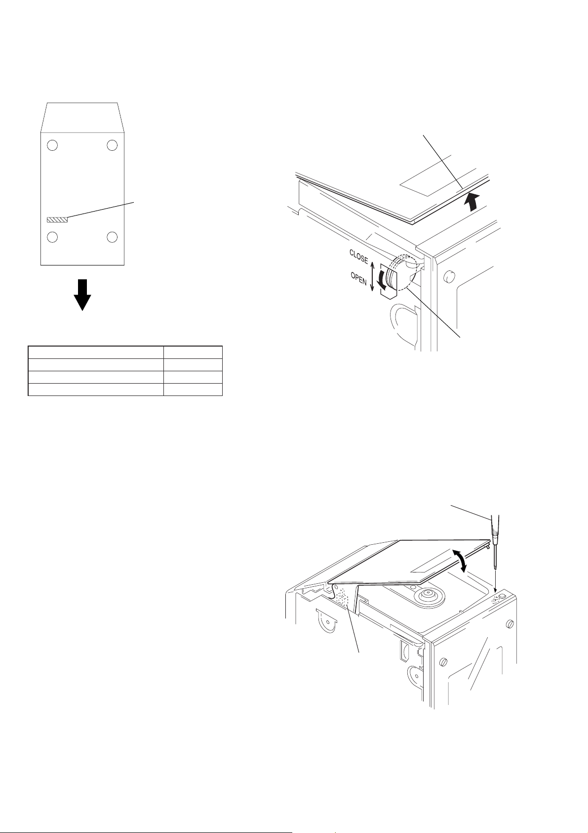
MODEL IDENTIFICATION
— Bottom view —
PART No.
Front Panel
MODEL PART No.
AEP and UK models 4-212-516-0π
Singapore and Hong Kong models 4-212-516-1π
US and Canadian models 4-212-516-3π
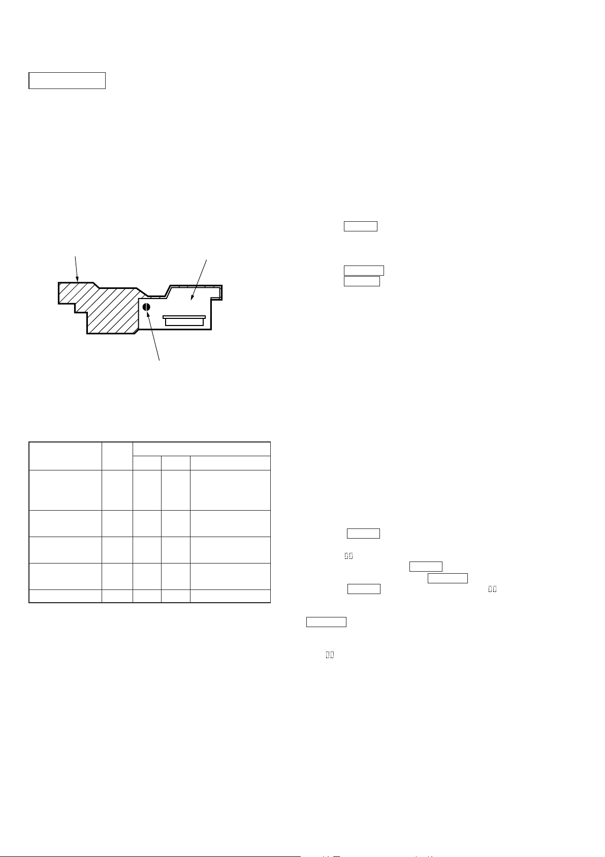
HOW TO OPEN THE CD LID
1. Remove Side panel (L), (R). (Refer to page 12)
2. Rotate the Worm gear ass’y to direction of the arrow A.
CD lid
A
Worm gear ass’y
LASER DIODE AND FOCUS SEARCH OPERATION
CHECK
1. Open the CD lid.
2. Turn on S104 and S916 as following figure.
3. Confirm that the laser diode emission while observing the objecting lens. When there is no emission, Auto Power Control
circuit or Optical Pick-up is broken.
Objective lens moves up and down once for the focus search.
Insert a precision
screwdriver and
push S916.
S104: ON
– 8 –
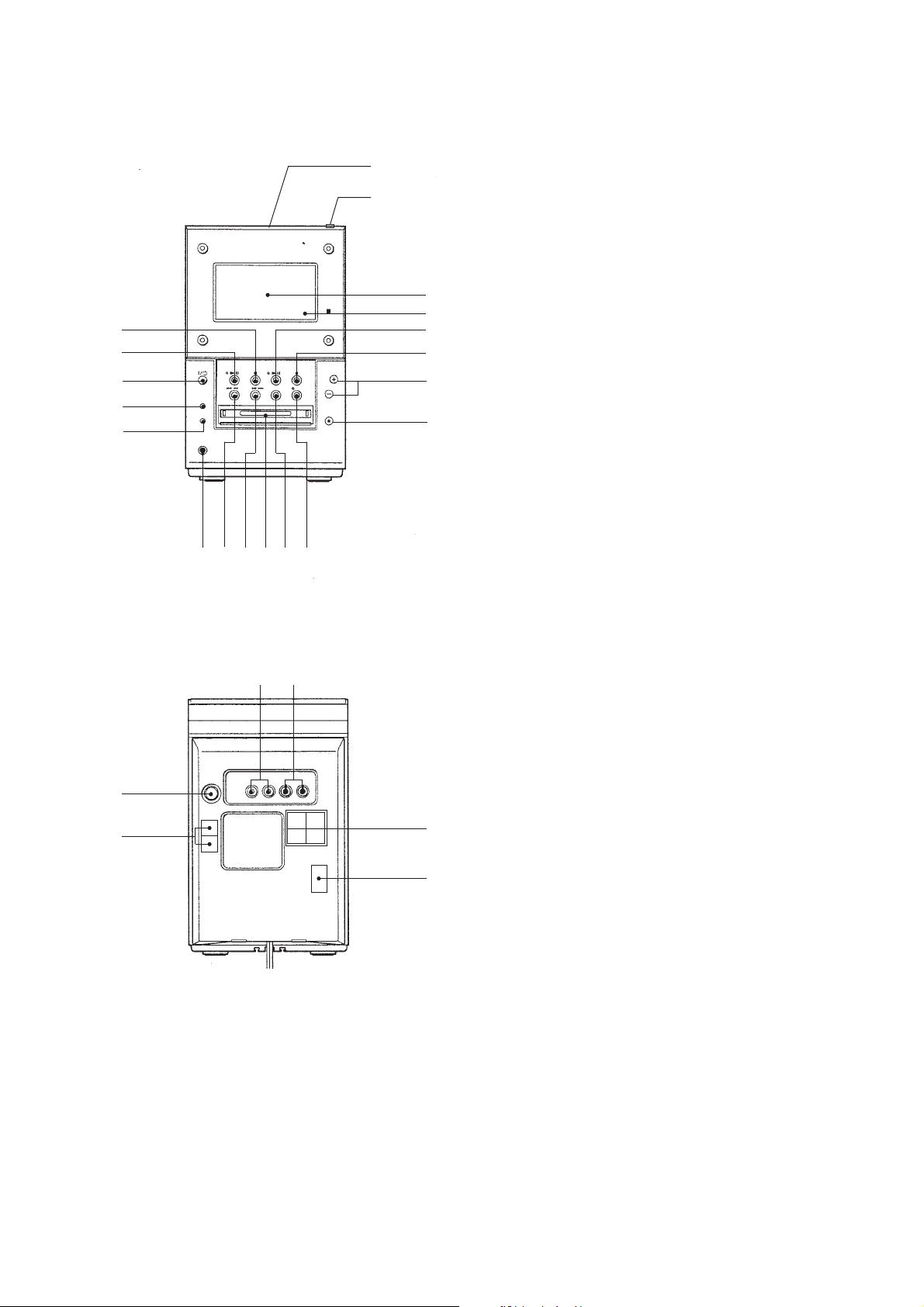
LOCATION OF CONTROLS
• Front view
SECTION 2
GENERAL
9
!º
!¡
!™
!£
!¢
!∞
1(Upper panel)
2(Upper panel)
3
4
5
6
7
8
!• !ª!¶!§
1 CD lid
2 6 (CD) button
3 Display window
4 Remote sensor
5 MD ^ button and indicator
6 MD p button
7 VOLUME +/– buttons
8 6 (MD) button
9 CD p button
0 CD ^ button and indicator
!¡ 1/u button
!™ FUNCTION button
!£ TUNER/BAND button
!¢ PHONES jack
!∞ =0 button
!§ )+ button
!¶ MD disc slot
!• CD-MD SYNC button
!ª REC button and indicator
• Rear view
5
6
1 2
1 TAPE OUT jacks
2 TAPE IN jacks
3 SPEAKER terminals
4 VOLTAGE SELECTOR switch
(Singapore and Hong Kong models)
5 FM ANTENNA terminal
6 AM ANTENNA terminals
3
4
– 9 –
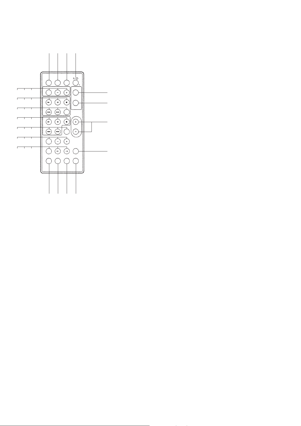
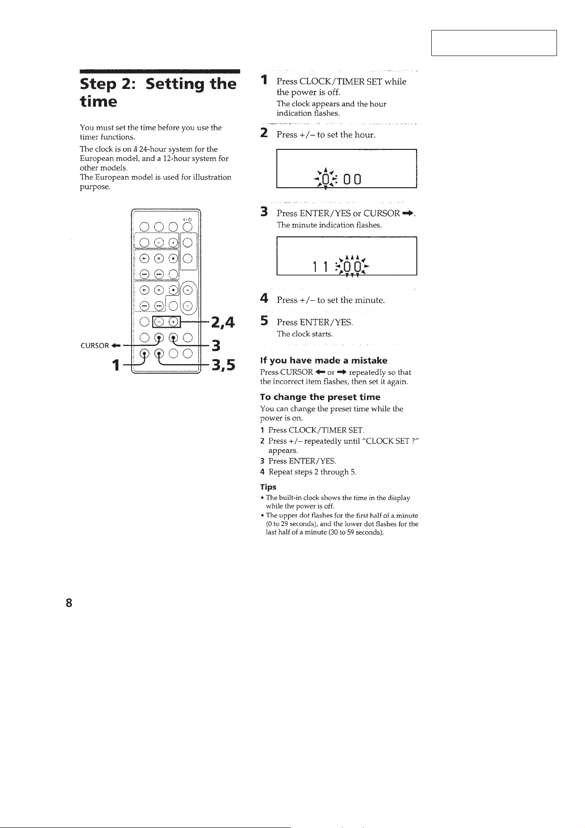
• REMOTE CONTROLLER
9 !º !¡
!™ !£ !¢
!∞ !§ !¶
!• !ª @º
@¡ @™ @£
@¢ @∞ @§
@¶ @• @ª
2 3 4
1
#º #¡ #™ #£
5
6
7
8
1 FUNCTION button
2 SLEEP button
3 CD, OPEN/CLOSE button
4 1/u button
5 MODE, PLAY/TUNING button
6 REPEAT, STEREO/MONO button
7 VOL +/– buttons
8 DBFB button
9 BAND, TUNER button
0 –, PRESET button
!¡ +, PRESET button
!™ MD ( button
!£ MD P button
!¢ MD p button
!∞ MD = button
!§ MD + button
!¶ MD SCROLL button
!• CD ( button
!ª CD P button
@º CD p button
@¡ CD = button
@™ CD + button
@£ DISPLAY, CHARACTER button
@¢ EDIT button
@∞ – button
@§ + button
@¶ SELECT, CLOCK/TIMER button
@• N, CURSOR button
@ª n, CURSOR button
#º SET, CLOCK/TIMER button
#¡ YES, ENTER button
#™ NO, CANCEL button
#£ MUSIC MENU button
– 10 –
This section is extracted from
instruction manual.
– 11 –
SECTION 3
)
)
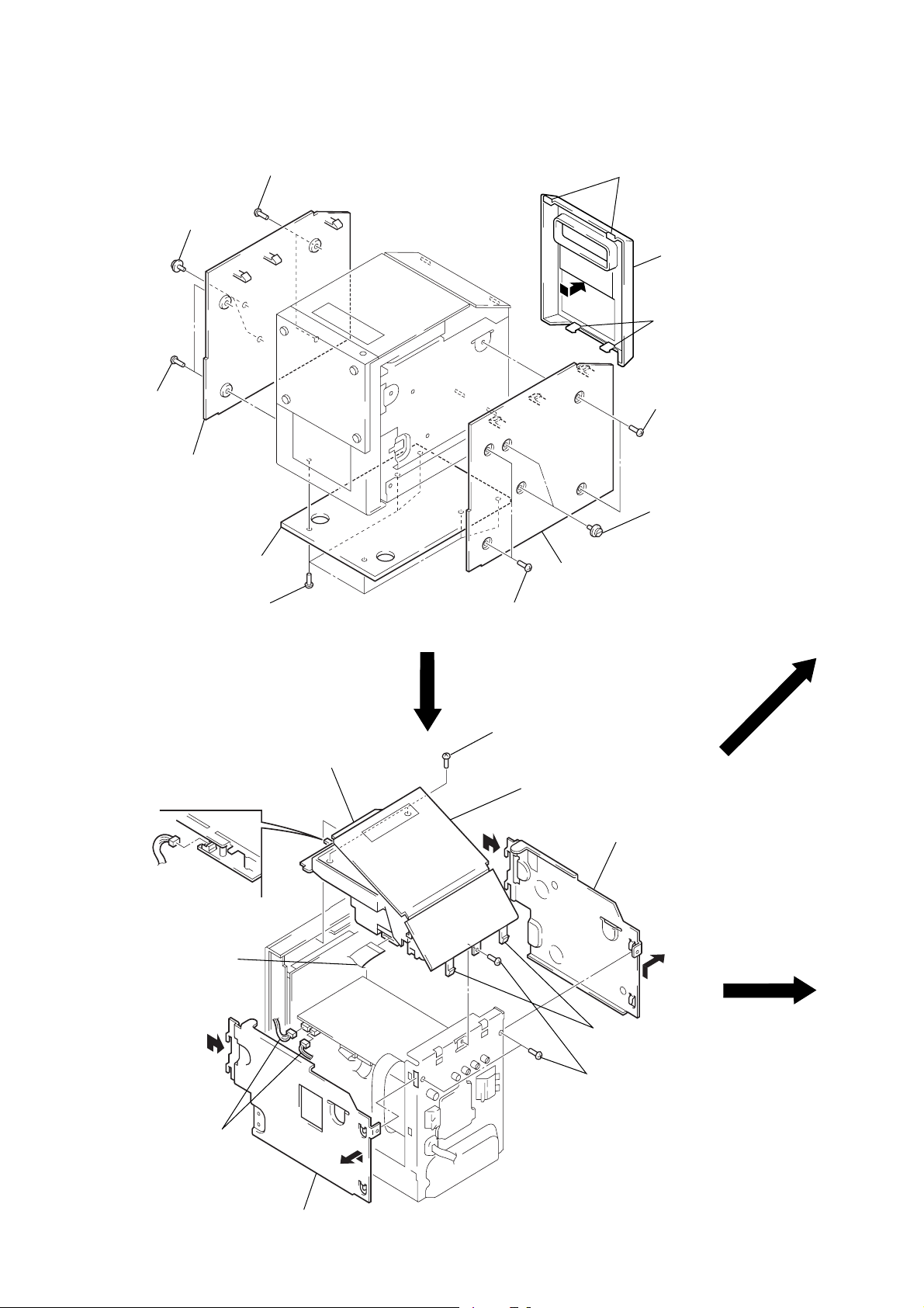
DISASSEMBLY
Note: Follow the disassembly procedure in the numerical order given.
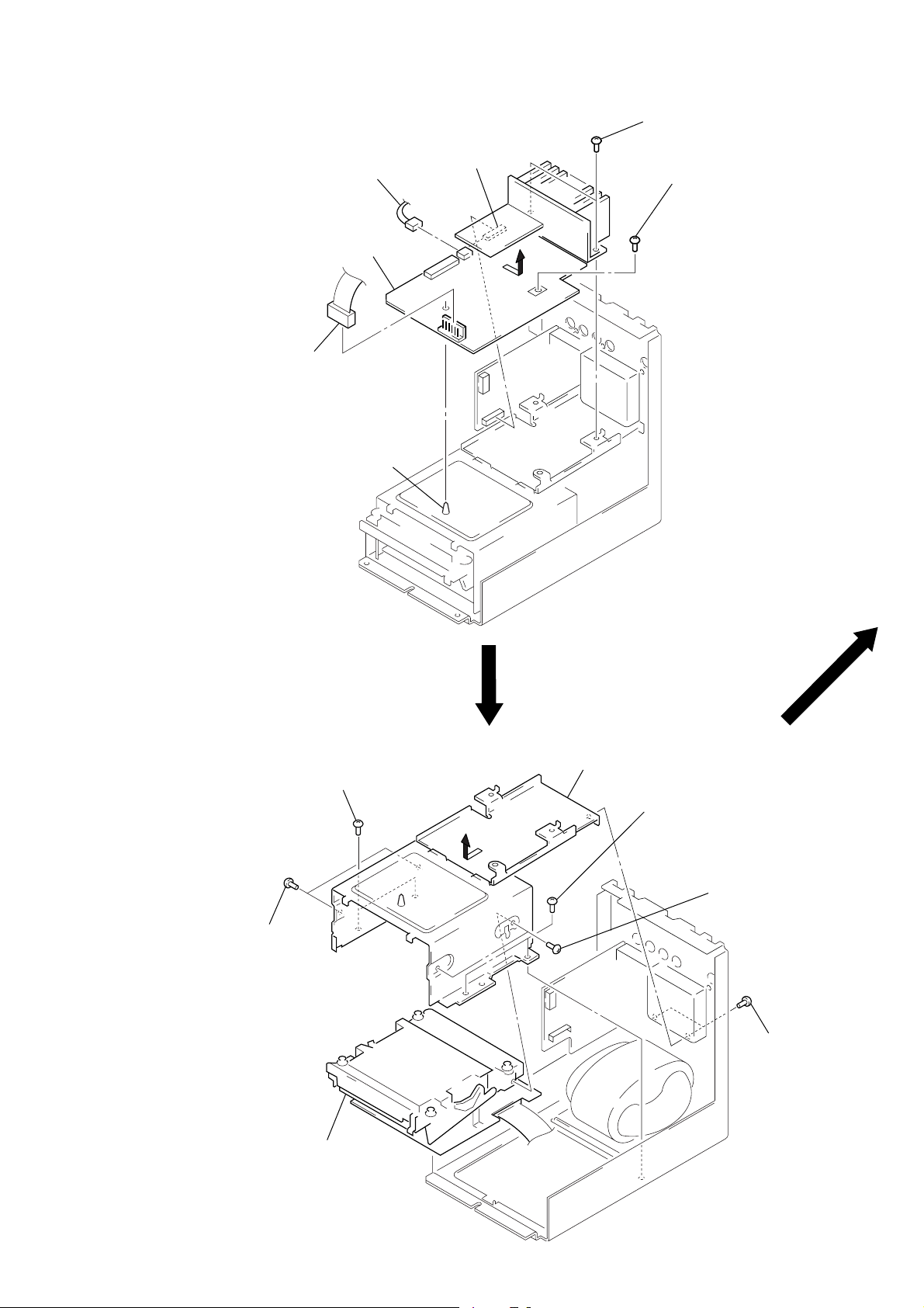
1
PANEL, COVER
2
1
two screws
(case 3 TP2)
two screws
3
side panel (L)
two screws
(case 3 TP2)
5
two claws
6
rear cover
4
two claws
1
two screws
(case 3 TP2
2
two screws
CD SECTION
7
8
bottom cover
7
six screws
(BVTT 3
8
connector
(CN902)
flat wire (19 core)
(CN102)
3
side panel (R)
1
×
6)
4
CD section
two screws
(case 3 TP2)
2
two screws
(BVTP 3
1
C
×
8)
Open the CD lid.
6
Remove the reinfocement (L
to direction of arrow C – D.
D
A
8
two connectors
(CN702, 707)
B
5
Remove the reinfocement (R)
to direction of arrow
A
– B.
– 12 –
3
two claws
2
three screws
(BVTP 3
×
8)
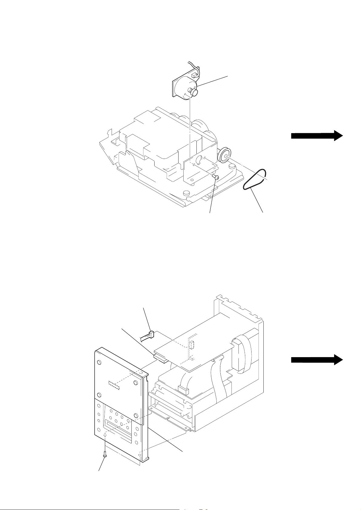
CD LID OPEN/CLOSE MOTOR
2
two screws
(B 2.6
3
×
3)
CD lid open/close
motor
1
belt
FRONT PANEL SECTION
3
connector
(CN705)
1
connector
(CN104)
4
front panel section
2
two screws
(BV/ring)
– 13 –
CD BASE UNIT
)
2
Remove the CD base unit
section to direction of
the arrow
A
.
5
two screws
(PTPWHM 2.6)
1
two screws
(BVTP 2.6)
A
3
screw
(PTT 2.6
×
5)
4
1
earth lug
5
two screws
(PTPWHM 2.6
6
CD base unit
two screws
(BVTP 2.6)
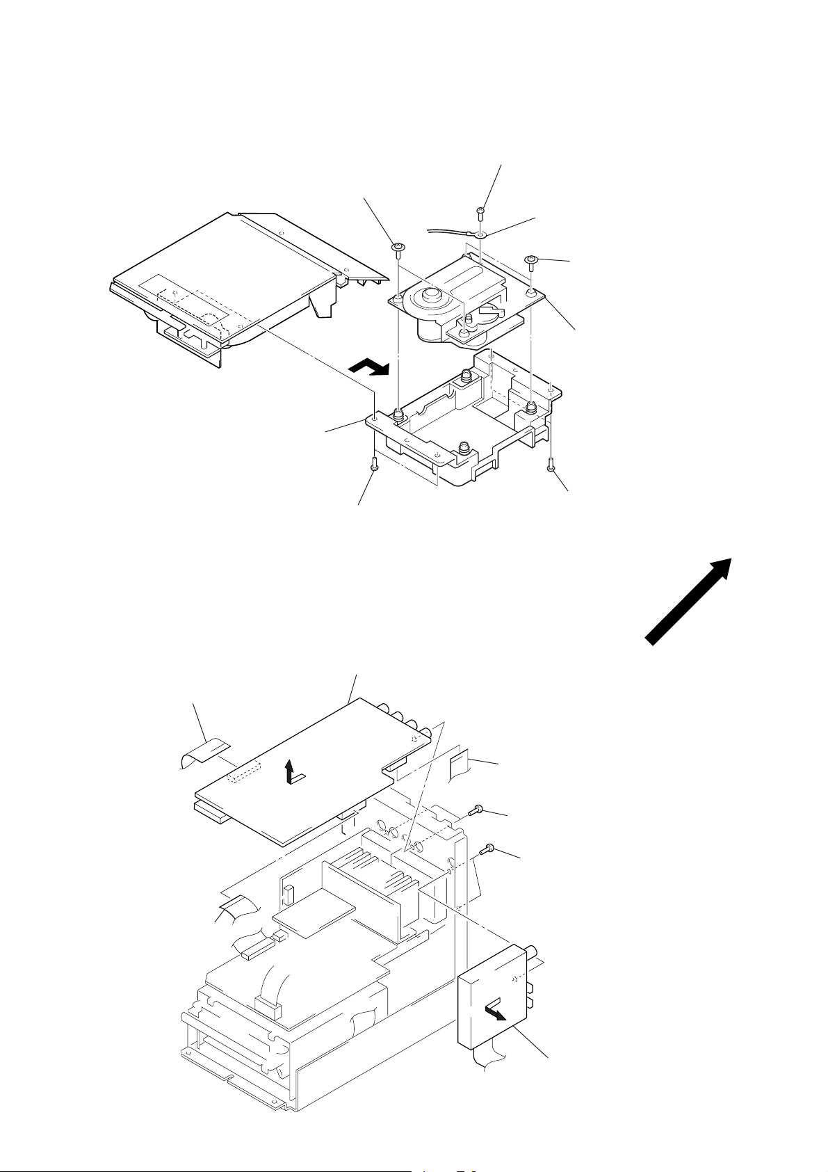
TUNER, MAIN BOARD
3
flat wire (31 core)
(CN706)
3
flat wire (25 core)
(CN704)
5
Remove the MAIN board
to direction of the arrow
B
B
.
3
flat wire (15 core)
(CN703)
4
two screws
(BVTP 3
1
A
×
8)
two screws
(BVTP 3
×
8)
– 14 –
2
Remove the tuner to
direction of the arrow
A
.
POWER BOARD
)
1
connector
(CN501)
6
Remove the POWER board
to direction of the arrow
1
connector
(CN501)
4
PC board holder
A
3
two screws
5
connector
(CN503)
.
A
(BVTP 3
2
×
8)
screw
(BVTT 3
×
6
MD MECHANISM DECK
4
two screws
(BVTT 2
5
2
two screws
(BVTT 3
×
3)
MD mechanism deck
×
6)
A
3
Remove the MD mechanism
deck section to direction
of the arrow
A
.
2
two screws
(BVTT 3
×
6)
4
two screws
(BVTT 2
1
two screws
(BVTP 3
×
3)
×
8)
– 15 –
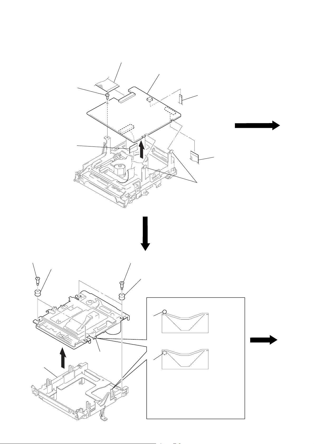
BD BOARD
)
3
screw
(BVTT 2
2
flexible board
(CN101)
1
flat wire (25 core)
(CN107)
5
BD (MD) board
×
4)
2
flexible board
(CN104)
1
flat wire (25 core
(CN106)
4
two claws
SUB CHASSIS
1
two step screws
3
sub chassis
2
insulator
part
A
1
two step screws
2
insulator
part
part
A
A
Take care so that the part
may be right position when installing.
NG
OK
A
– 16 –
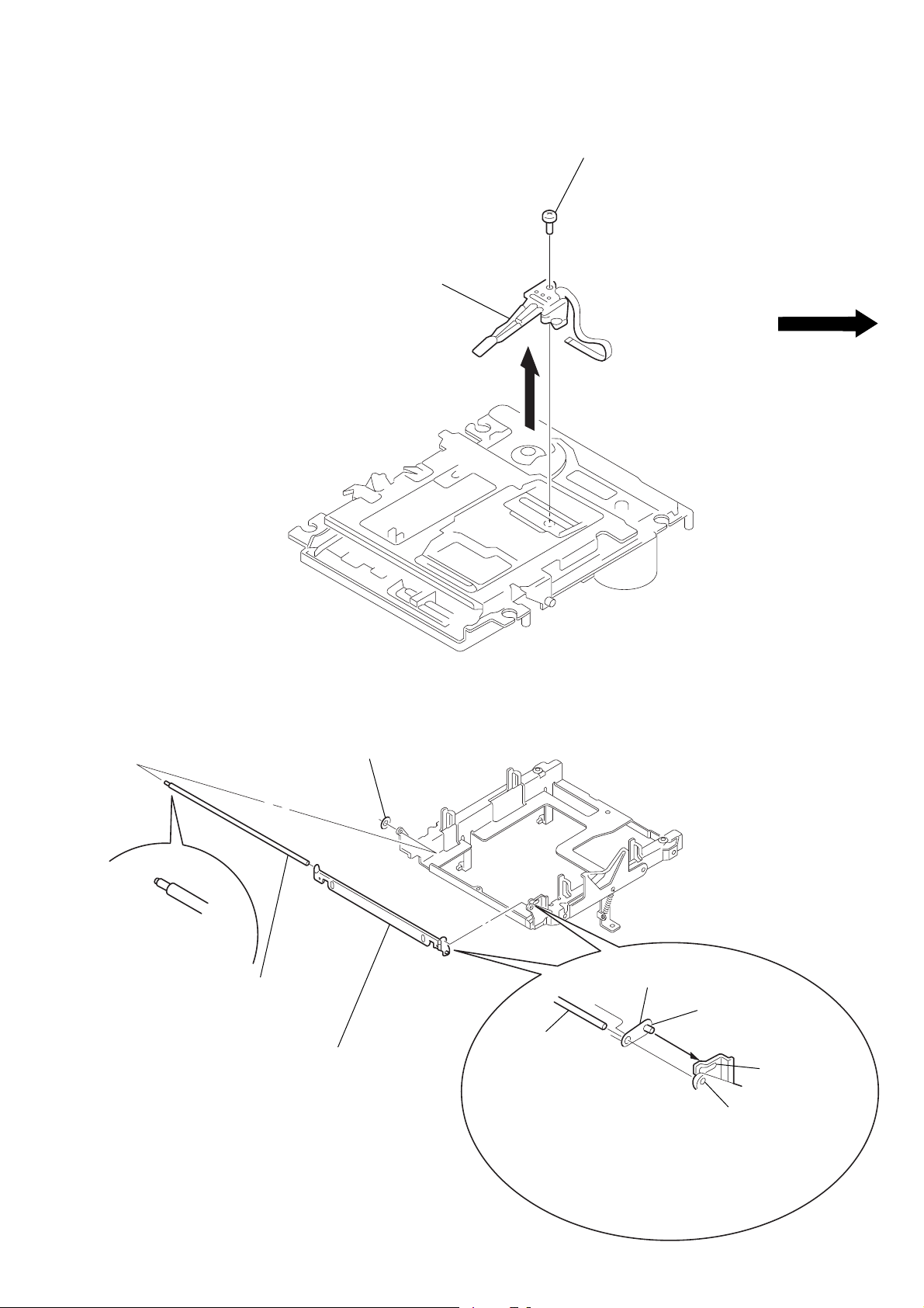
OVER WRITE HEAD
2
over write head
1
screw (P 1.7 × 6)
SHUTTER ASS’Y
2
shaft (shutter) A
3
1
stopper washer
shutter ass’y
shutter ass’y
shaft (shutter) B
shaft (shutter) A
hole B
hole A
When installing, install the shaft (shutter) A
into the hole as show in the figune before
installing the shaft (shutter) B into the hole B.
– 17 –
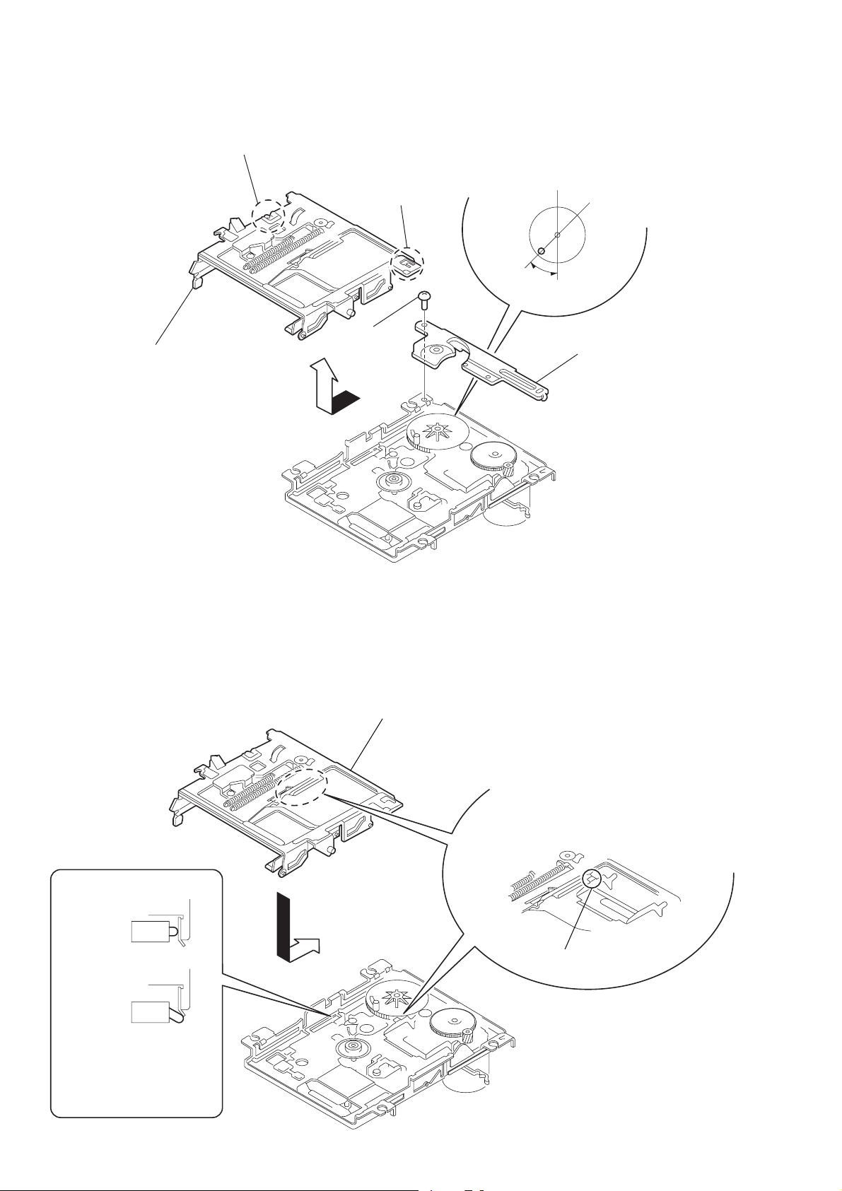
SLIDER COMPLETE ASS’Y
claw
4
Remove the slider complete ass’y
in the direction of arrow with putting
out of two claws.
1
special screw
(M 1.7
×
1.4)
claw
3
Set the shaft of gear (LB) to be at the
position in the figure.
2
retainer (gear)
NOTE FOR INSTALLATION
• SLIDER COMPLETE ASS’Y
OK
NG
slider ass’y
Install the part A of lever (head up)
to pass over the slider complete ass’y.
part A
Take care no to damage
the detective switch.
– 18 –

SECTION 4
SERVICE MODE
Change-over of AM (MW) Tuner Step between 9 kHz and 10 kHz
• A step of AM (MW) channels can be changed over between 9 kHz and 10 kHz.
Procedure:
1. Press 1/u button to turn the set ON.
2. Select the function “TUNER”, and press [TUNER/BAND] button to select the BAND “AM (MW)”.
3. Press 1/u button to turn the set OFF.
4. Press [FUNCTION] and 1/u buttons simultaneously, and the display of fluorescent indicator tube changes to “AM (MW) 9 kHz
STEP” or “AM (MW) 10 kHz STEP”, and thus the channel step is changed over.
Change-over of LW Tuner Step between 1 kHz and 3 kHz
• A step of LW channels can be changed over between 1 kHz and 3 kHz.
Procedure:
1. Press 1/u button to turn the set ON.
2. Select the function “TUNER”, and press [TUNER/BAND] button to select the BAND “LW”.
3. Press 1/u button to turn the set OFF.
4. Press [FUNCTION] and 1/u buttons simultaneously, and the display of fluorescent indicator tube changes to “LW 1 kHz STEP” or
“LW 3 kHz STEP”, and thus the channel step is changed over.
ATT Change-over of TAPE input
Procedure:
1. Press 1/u button to turn the set ON.
2. Select the function “TAPE”.
3. Press 1/u button to turn the set OFF.
4. Press 1/u button while pressing [FUNCTION] button. The power is turned on and the display of fluorescent indicator tube changes
to “Attenuator ON” or “Attenuator OFF”, then ATT change-over of TAPE input is completed.
CD tracking balance display
Procedure:
1. Press 1/u button to turn the set ON.
2. Select the function “CD”.
3. Press
4. The display of fluorescent indicator tube shows you the following message.
LED and Fluorescent Indicator Tube All Lit, Key Check Mode
Procedure:
1. Press two buttons [VOLUME–] and [TUNER/BAND] simultaneously.
2. LEDs and fluorescent indicator tube are all turned on.
3. When the [FUNCTION] button is pressed, the fluorescent indicator tube lights up in the order of; partial lighting 1 n partial lighting
4. Press p (CD) button, and the key check mode is activated.
5. In the key check mode, the fluorescent indicator tube displays “KEY=0 JOG=0”. Each time a button is pressed, “KEY=” value
6. To exit from this mode, press order all buttons (13 buttons), and press any button, or disconnect the power cord.
SUB CLOCK CHECK
Procedure:
1. Connect an oscilloscope to IC707 pin (¡ and ground of the MAIN board.
2. Press two buttons [VOLUME–] and [REC] simultaneously, and the fluorescent indicator tube displays “32.768 kHz (91)”.
3. To check the signal on oscilloscope becomes 32 kHz square wave.
4. Press 1/u button to exit.
[TUNER/BAND] button while pressing p (CD) button.
CD TR. BAL. ππ
2 n all lit n partial lighting 1 n.
When the [VOLUME+/–] button is pressed, the LED lighting pattern changes.
To end without switching to the key check mode, press the 1/u button to turn off the power.
increases. However, once a button is pressed, it is no longer taken into account.
“JOG=” Value increases like 1, 2, 3 ... if press [VOLUME+] button, or it decreases like 99, 98, 97 ... if press [VOLUME–] button.
– 19 –

SECTION 5
TEST MODE
5-1. PRECAUTIONS FOR USE OF TEST MODE
Recording Laser Emission Mode
• Continuous recording mode (CREC MODE)
• Traverse adjustment mode (EFBAL ADJUST)
• Laser power adjustment mode (LDPWR ADJUST)
• Laser power check mode (LDPWR CHECK)
• Traverse (MO) check (EF MO CHECK)
• Traverse (MO) adjustment (EF MO ADJUST)
5-2. SETTING THE TEST MODE
With the power off, press the =0 button while pressing the [VOLUME–] button.
5-3. EXITING THE TEST MODE
Press the p (MD) button while pressing the [FUNCTION] button. The STANDBY state will be set and the test mode will be cleared.
5-4. BASIC OPERATIONS OF THE TEST MODE
All operations are performed using the [VOLUME+/–] button, p (CD) button, and ^ (CD) button.
The functions of these buttons are as follows.
Function name
VOLUME +/– button
p (CD) button
^ (CD) button
Function
Changes parameters and modes
Proceeds onto the next step. Finalizes input.
Returns to previous step. Stops operations.
– 20 –
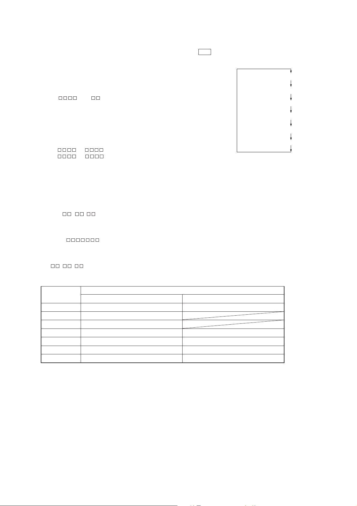
5-5. SELECTING THE TEST MODE
There are altogether 26 test modes, shown in the following table. Press the [VOLUME+] b utton to the mode belo w the current mode in the
table while press the [VOLUME–] button to the mode above. Each time the ^ (CD) button is pressed, the display changes in the
following order;
“TEMP CHECK” n “TEMP ADJUST” n “SLED MOVE” n “CPLAY 2 MODE” n “TEMP CHECK”…
Display
TEMP CHECK
LDPWR CHECK
EF MO CHECK
EF CD CHECK
FBIAS CHECK
CPLAY MODE
CREC MODE
Scurve CHECK
VERIFY MODE
DETRK CHECK
TEMP ADJUST
LDPWR ADJUST
EF MO ADJUST
EF CD ADJUST
FBIAS ADJUST
EEP MODE
MANUAL CMD
SVDATA READ
ERR DP MODE
SLED MOVE
ACCESS MODE
0920 CHECK
WRITE sure?
HEAD ADJUST
CPLAY2 MODE
CREC2 MODE
Contents
Temperature compensation offset check
Laser power check
Traverse (MO) check
Traverse (CD) check
Focus bias check
Continuous playback mode
Continuous recording mode
S curve check
Non-volatile memory check
Detrack check
Temperature compensation offset adjustment
Laser power adjustment
Traverse (MO) adjustment
Traverse (CD) adjustment
Focus bias adjustment
Nonvolatile memory control
Command transfer
Status display
Error history display, clear
Sled check
Access check
Outermost circumference check
Non-volatile memory Initialize
Head position check
Continuous playback mode
Continuous recording mode
Mark
(X)
(X)
(X)
(X) (!)
(X)
(X)
(X)
(X)
(X)
(X) (!)
(X)
(X)
(X)
• For details of each adjustment mode, refer to the items in “6. Electrical Adjustments”. For details of “ERR DP MODE”, refer to the self-
diagnosis function on page 2.
• If other modes are set accidentally, press the ^ (CD) button to exit that mode.
• As items marked (X) in the “Mark” column are not used during servicing, they are not described here. If these modes are set acciden-
tally, press the ^ (CD) button to exit the mode. Be especially careful with items marked (!) as they will overwrite the non-volatile
memory, and as a result, the unit will not operate normally.
5-5-1. Operating the Continuous Playback Mode
1. Entering the continuous playback mode
1 Set the disc in the unit. (Recordable discs or discs for playback only.)
2 Press the [VOLUME+/–] button and display “CPLAY MODE”.
3 Press the p (CD) button to change the display to “CPLAY MID”.
4 When access completes, the display changes to “C = AD = ”.
Note: The numbers “ ” displayed indicate the error rates and “ADER”.
2. Changing the part to be played back
1 When the p (CD) button is pressed during continuous playback, the display changes as below , and the played back part can be
changed.
“CPLAY MID” n “CPLAY OUT” n “CPLAY IN”
2 When access completes, the display changes to “C = AD = ”.
Note: The numbers “ ” displayed indicate the error rate and “ADER”.
– 21 –
3. Ending the continuous playback mode
1 Press the ^ (CD) button. The display changes to “CPLAY MODE”.
2 Press the 6 (MD) button to remove the disc.
Note: The playback start addresses for IN, MID, and OUT are as follows. To display the playback position address on the display, press the 1/u
button to display “CPLAY ( )”.
IN: 40h cluster
MID: 300h cluster
OUT: 700h cluster
5-5-2. Operating the Continuous Recording Mode
1. Entering the continuous recording mode
1 Set a recordable disc in the unit. (Refer to Note 3.)
2 Press the [VOLUME+/–] button and display “CREC MODE”.
3 Press the p (CD) button to change the display to “CREC MID”.
4 When access completes, the display changes to “CREC ( )” and the REC display lights up.
Note: The numbers “ ” displayed indicate the recording position address.
2. Changing the part to be recorded
1 When the p (CD) button is pressed during continuous recording, the display changes as below and the recorded part can be
changed. The REC display is off while changing.
“CPLAY MID” n “CPLAY OUT” n “CPLAY IN”
2 When access completes, the display changes to “CREC ( )” and the REC display lights up.
Note: The numbers “ ” displayed indicate the recording position address.
3. Ending the continuous recording mode
1 Press the ^ (CD) button. The display changes to “CREC MODE”, and the REC goes off.
2 Press the 6 (MD) button to remove the disc.
Note 1: The recording start addresses for IN, MID, and OUT are as follows.
IN: 40h cluster
MID: 300h cluster
OUT: 700h cluster
Note 2: The ^ (CD) button can be used to stop recording anytime.
Note 3: Do not perform continuous recording for long periods of time above 5 minutes.
Note 4: During continuous recording, be careful not to apply vibration.
5-5-3. Non-Volatile Memory Mode (EEP MODE)
This mode reads and writes the contents of the non-volatile memory.
It is not used in servicing. If set accidentally, press the ^ (CD) button immediately to exit it.
5-6. FUNCTIONS OF OTHER BUTTONS
Function
(P (MD)
p (MD)
) +
= 0
CD-MD SYNC
1/u
6 (MD)
Sets continuous playback when pressed in the STOP state. Turns ON/OFF the tracking servo when pressed
during continuous playback.
Stops the continuous playback and recording.
Moves the sled to the external circumference only while the button is pressed.
Moves the sled to the internal circumference only while the button is pressed.
Switches between pit and groove when pressed.
Switches the displayed contents when pressed.
Ejects the disc.
Contents
– 22 –
5-7. DISPLAYS DURING TEST MODE
Mode display
Error rate display
Address display
Auto gain display (Not used in servicing)
Detrack check display (Not used in servicing)
IVR display (Not used in servicing)
The display changes according to the following sequence each time the 1/u button is pressed.
1. Mode display
“TEMP ADJUST” and “CPLAYMODE” are displayed.
2. Error rate display
The error rate is displayed as follows.
C = AD =
C = :Indicates the C1 error.
AD = :Indicates ADER.
3. Address display
The address is displayed as follows. (MO: Recordable disc, CD: Disc for palyback only)
When the [CD-MDSYNC] button is pressed, the display will switch between groove
and pit.
h = s = (MO pit and CD)
h = a = (MO groove)
h = Indicates the header address.
s = Indicates the SUBQ address.
a = Indicates the ADIP address.
Note: Displayed as “–” when servo is operated.
4. Auto gain display (Not used in servicing)
The auto gain is displayed as follows.
AG = / [ ]
5. Detrack check display (Not used in servicing)
The detrack is displayed as follows.
ADR =
6. IVR display (Not used in servicing)
IVR is displayed as follows.
[ ][ ][
Meanings of other displays
Display
REC
ATT
SHUFFLE
TRACK
DISC
LEVEL-SYNC
SYNC
Recording mode ON Recording mode OFF
ABCD adjustment completed
Focus auto gain OK
Pit Groove
High reflection rate Low reflection
CLV-S CLV-A
CLV LOCK CLV UNLOCK
When Lit When Off
Contents
– 23 –
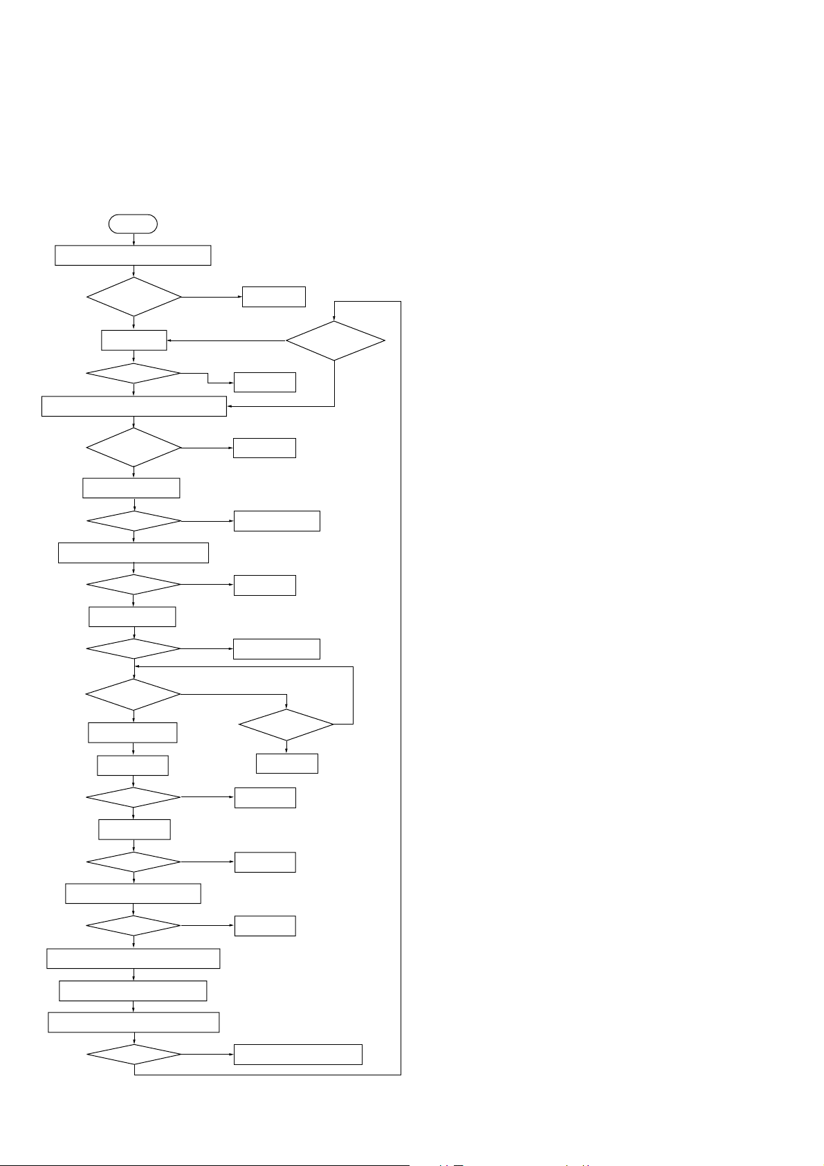
5-8. AGING MODE
This unit is provided with an aging mode.
In this mode, MD and CD operations are performed alternately according to the following sequence.
Aging will be carried out continuously unless an error occurs.
If an error occurs, the status and number of cycles are displayed alternately, and operations stop. (Refer to Table 1.)
Aging Mode Sequence
Start
Turn ON Power using function MD
MD TOC READ
Can read
MD all erase
Blank disc
YES
CD function is set and CD TOC is read
CD TOC OK?
YES
CD synchro standby
OK?
YES
CD last track search pause state
OK?
YES
CD synchro starts
OK?
YES
Cannot read
Above 20
NO
NO
NO
NO
NO
Message 6
MD last track
Less than 20
Message 1
Message 7
Message 2 or 8
Message 9
Message 3 or 0
Synchro ends?
MD function is set
CD tray opens
OK?
YES
CD tray closes
OK?
YES
MD last track (for 3 sec.) play
OK?
YES
Power goes off and MD TOC is written
Aging cycle number is displayed
Power turns ON and MD TOC is read
OK?
YES
NO
NO
NO
NO
Playing CD?
NG
Message !º
Message !¡
Message !™
Message 4
Message 5 or Message 6
OK
– 24 –

Procedure:
1. Load a recordable disc (MD) and CD test disc (YEDS-18). (*Note 1)
2. While pressing the [VOLUME–] button, press the )+ button.
3. Aging is executed in the above sequence.
4. To end, press the p (CD or MD) button.
*Note 1: Any CD can be used, but one with a short last track is recommended. The time of one aging cycle will be longer if the last track is long.
Table 1. Messages and Main Causes When Aging Stops
Also use a CD in which the length of the last track x 20 does not exceed the recording time of the recording MD.
No.
1
MD A Erase NG
2
MD R-Pause NG
3
MD D-input NG
4
MD Play NG
5
MD TOC NG
6
MD No Disc NG
7
CD No Disc NG
8
CD Pause NG
9
CD Search NG
0
CD Play NG
!¡
CD Open NG
!™
CD Close NG
Error Messages
Details of Error
Cannot MD all erase.
Cannot set MD Rec Pause.
Cannot lock MD digital in.
Cannot play last track.
MD TOC are different.
Cannot read MD TOC.
Cannot read CD TOC.
Cannot set CD pause in
CD synchro mode.
Cannot search last track on CD.
Cannot play last track on CD.
Cannot open CD tray.
Cannot close CD tray.
Main Causes
A disc for playback only was used. The rec-proof tab is set to
protect. Disc error, etc.
Disc is full, etc.
Access error, etc.
No. of total tracks does not match logic value.
Disc error, etc.
Optical defect, spindle defect (including motor), cannot read Q
data, disc defect (scratches, etc.), bad focus, bad GFS, etc.
Disc defect (scratches, etc.), cannot read Q data, etc.
Optical defect, sled, tracking defect (including motor), cannot
read Q data, disc defect (scratches, etc.).
Optical defect, cannot read Q data, disc defect (scratches, etc.),
etc.
LOAD OUT SW defect
LOAD IN SW defect
– 25 –
SECTION 6
ELECTRICAL ADJUSTMENTS
MD SECTION
6-1. PRECAUTIONS FOR CHECKING LASER
DIODE EMISSINON
When checking the emission of the laser diode during adjustments,
never view directly from the top as this may cause blindness.
6-2. PRECAUTIONS FOR USE OF OPTICAL
PICK-UP (KMS-260A)
As the laser diode in the optical pick-up is easily damaged by static
electricity, solder the laser tap of the fle xible board when using it.
Before disconnecting the connector, solder first. Before connecting the connector, be careful not to remove the solder. Also take
adequate measures to prevent damage by static electricity. Handle
the flexible board with care as it breaks easily.
pick-up
laser tap
flexible board
Optical pick-up flexible board
6-3. PRECAUTIONS FOR ADJUSTMENTS
1) When replacing the following parts, perform adjustments and
checks marked ¬ in the order shown in the following table.
Optical
1. Temperature
compensation
offset adjustment
2. Laser power
adjustment
3. Traverse
adjustment
4. Focus bias
adjustment
5. Error rate check
Pick-up
\
IC171 D101 IC101, IC121, IC192
G¬¬ ¬
¬¬G ¬
¬¬G ¬
¬¬G ¬
¬¬G ¬
2) Perform the adjustment in the test mode.
After completing the adjustments, exit the test mode.
3) Perform the adjustments in the order shown.
4) Use the following tools and measuring devices.
• Check disc (MD) TDYS-1
(Parts No. 4-963-646-01)
• Laser power meter LPM-8001 (Parts No. J-2501-046-A)
or
MD Laser power meter 8010S (Parts No. J-2501-145-A)
• Oscilloscope (Measure after calibration of the probe).
• Digital voltmeter
• Thermometer
5) When observing several signals on the oscilloscope, etc., make
sure that VC and ground do not connect inside the oscilloscope.
(The VC and ground will short-circuit.)
BD (MD) Board
Note: When performing laser power checks and adjustment (electrical
adjustment), use of the new MD laser power meter 8010S (J-2501145-A) instead of the conventional laser po wer meter is conv enient.
It sharply reduces the time and trouble to set the laser power meter
sensor onto the objective lens of the pick-up.
6-4. CREATING THE CONTINUOUSLY
RECORDED DISC
• The disc is used for the focus bias adjustment and error rate
check.
The following describes how to create a continuously recorded
disc.
1. Insert a disc (blank disc) commercially available.
2. Press the [VOLUME+/–] button to display “CREC MODE”.
3. Press the p (CD) button to display “CREC MID”.
“CREC (0300)” will be momentarily displayed and recording
started.
4. Complete recording within 5 minutes.
5. Press the ^ (CD) button and stop recording .
6. Press the 6 (MD) button and remove the disc.
Create the continuous recorded disc for adjusting the focus bias
and checking the error rate as described above.
Note:
• Be careful not to apply vibrations during continuous recording.
6-5. TEMPERATURE COMPENSATION OFFSET
ADJUSTMENT
Save the current temperature data in the non-volatile memory as
the 25 °C standard data.
Notes:
1. Normally, this adjustment should not be preformed.
2. Set the surrounding temperature to 22 to 28 °C when performing this
adjustment.
Also perform this adjustment immediately after the power is turned
on when the internal temperature of the unit is the same as the surrounding temperature (22 to 28 °C).
3. After replacing D101, perform this adjustment after the temperature
of parts reach the surrounding temperature.
Adjusting Procedure:
1. Press the [VOLUME+/–] button, to display “TEMP ADJUST”.
2. Press the p (CD) button and select the “TEMP ADJUST”
mode.
3. “TEMP= ” and the current temperature data are displayed.
4. To save the data: Press the p (CD) button.
If not saving the data: Press the ^ (CD) button.
5. When the p (CD) button is pressed, “TEMP= SAVE” is
displayed, and then “TEMP ADJUST” is displayed again.
“TEMP ADJUST” is displayed again immediately after the
^ (CD) button is pressed.
Specifications:
TEMP= should be E0 to EF . F0 to FF, 00 to 0F, 10 to 1F and 20
to 2F.
– 26 –
6-6. LASER POWER ADJUSTMENT
r
r
VC
A
B
Specified value : A = B
VC
A
B
Specified value : A = B
v
6-7. TRAVERSE ADJUSTMENT
Connection :
Optical pick-up
objective lens
BD (MD) board
TP (I+3V)
TP (IOP)
Laser powe
meter
Digital volt mete
Adjusting Procedure:
1. Set the laser power meter on the objective lens of the optical pickup from the disc slot. (If it cannot be set properly, press the
=0 or )+ button to move the optical pick-up).
Connect the digital voltmeter to TP (I+3V) and TP (IOP) of
the BD (MD) board.
2. Press the [VOLUME+/–] button to display “LDPWR ADJUST”.
(Laser power: For adjustment)
3. Press the p (CD) button once to display “LD 0.9 mW $ ”.
4. Press the [VOLUME+/–] button so that the laser power meter
reads 0.86 to 0.92 mW. Set the range knob of the laser power
meter to 10 mW, press the p (CD) button, and save the adjustment results in the non-volatile memory. (“LD SAVE $
” is displayed momentarily.)
5. “LD 7.0 mW $ ” is next displayed.
6. Press the [VOLUME+/–] button so that the laser power meter
reads 6.9 to 7.1 mW, press the p (CD) button, and save the
adjustment results in the non-volatile memory. (“LD SAVE $
” is displayed momentarily.)
Note: Do not emit 7.0 mW continuously for more than 15 seconds.
7. Press the [VOLUME+/–] button to display “LDPWR CHECK”.
8. Press the p (CD) button once to display “LD 0.9 mW $ ”.
Check that the laser power meter reading is 0.85 to 0.91 mW.
9. Press the p (CD) button another time to diaplay “LD 7.0
mW $ ”.
Check that the readings of the laser power meter and digital
voltmeter become the specified value.
Specified V alue :
Laser power meter reading : 7.0 ± 0.1 mW
Digital voltmeter reading : Value displayed on optical pick-up label ± 10%
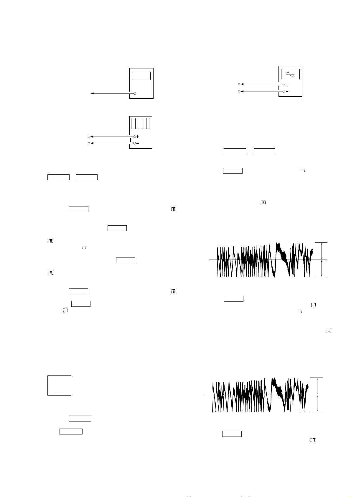
Connection :
BD (MD) board
TP69 (TEO)
TP1003 (VC)
Oscilloscope
V: 0.5 v/div H: 10 ms/di
Input: DC mode
Adjusting Procedure:
1. Connect an oscilloscope to TP69 (TEO) and TP1003 (VC) of
the BD (MD) board.
2. Load a recordable disc (any available on the market). (Refer
to Note 1.)
3. Press the =0 or )+ button to move the optical
pick-up outside the pit.
4. Press the [VOLUME+/–] button to display “EFBAL ADJUST”.
5. Press the p (CD) button to display “EFB = MO-R”.
(Laser power READ power/Focus servo ON/tracking servo
OFF/spindle (S) servo ON)
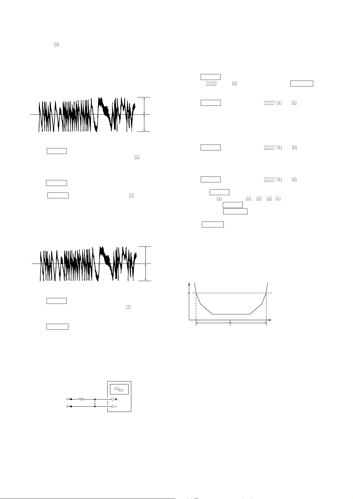
6. Press the [VOLUME+/–] button so that the oscilloscope waveform becomes the specified value. (Press the [VOLUME+/–]
button changes the “EFB= ” value and the waveform.) The
waveform changes by about 2% everytime when adjusted.
Adjust as close as possible to the specified value.
(Read power traverse adjustment)
(Traverse Wavef orm)
7. Press the p (CD) button and save the adjustment results in
the non-volatile memory (displayed as “EFB = SAVE”
momentarliy and then displayed as “EFB = MO-W”).
8. Press the [VOLUME+/–] button so that the oscilloscope waveform becomes the specified value.
(Pressing the [VOLUME+/–] button changes the “EFB= ”
value and the waveform.) The wav eform changes by about 2%
everytime when adjusted. Adjust as close as possible to the
specified value.
(Write Power Traverse Adjustment)
(Optical pick-up label)
KMS
260A
27X40
B0825
N
Iop = 82.5 mA in this case
Iop (mA) = Digital voltmeter reading (mV)/1 (Ω)
10. Press the ^ (CD) button to display “LDPWR CHECK” and
stop the laser emission.
(The ^ (CD) button is effecti ve at all times to stop the laser
emission.)
(Traverse Wavef orm)
9. Press the p (CD) button to save the adjustment results in the
non-volatile memory (displayed as “EFB = SAVE”
momentarliy).
– 27 –
10. Next “EFB = MO-P” is displaed, the optical pick-up moves
A
A
e
to the internal circumference of the pit and servo is imposed.
11. Press the [VOLUME+/–] button so that the oscilloscope wa veform becomes the specified value.
The waveform changes by about 2% everytime when adjusted.
Adjust as close as possible to the specified value.
(Traverse Wavef orm)
VC
B
Specified value : A = B
12. Press the p (CD) button and save the adjustment results in
the non-volatile memory (displayed as “EFB = SAVE”
momentarliy).
“EFBAL: CD is next displayed and the disc stops rotating automatically.
13. Press the 6 (MD) button and remove the disc.
14. Load the check disc (MD) TDYS-1.
15. Press the p (CD) button to display “EFB = CD”. The
servo is imposed automatically.
16. Press the [VOLUME+/–] button so that the oscilloscope wa veform becomes the specified value.
The waveform changes by about 2% everytime when adjusted.
Adjust as close as possible to the specified value.
(Traverse Wavef orm)
VC
B
Specified value : A = B
17. Press the p (CD) button and save the adjustment results in
the non-volatile memory after “EFB = SAVE” is
momentarliy displayed.
“EFBAL ADJUST” is next displayed.
18. Press the 6 (MD) button and remove the check disc (MD)
TDYS-1.
6-8. FOCUS BIAS ADJUSTMENT
Adjusting Procedure :
1. Load a continuously recorded disc (Refer to 6-4. Creating the
Continuously Recorded Disc”).
2. Press the [VOLUME+/–] button and display “CPLA Y MODE”.
3. Press the p (CD) button to display “CPLAY MID”.
4. When “C = AD = ” is displayed, press the ^ (CD)
button.
5. Press the [VOLUME+/–] button to display “FBIAS ADJUST”.
6. Press the p (CD) button to display “ / a = ”.
The first four digits indicate the C1 error rate, the two digits
after the “/” indicate ADER and the two digits after “a =” indicate the focus bias value.
7. Press the [VOLUME+/–] button, and look for the focus bias
value at which the C1 error rate becomes approximately about
200. (Refer to Note 2).
8. Press the p (CD) button to display “ / b = ”.
9. Press the [VOLUME+/–] button, and look for the focus bias
value at which the C1 error rate becomes about 200.
The C1 error rate at this time should be almost same as the
value set in step 7.
10. Press the p (CD) button to display “ / c = ”.
11. Check that the C1 error rate is below 50 and that ADER is 00.
and press the p (CD) button.
12. If the value of “( )” in the “ - - ( )” displayed is
above 20, press the p (CD) button.
If below, press the ^ (CD) button and start from step 2
again.
13. Press the 6 (MD) button and remove the continuously recorded disc.
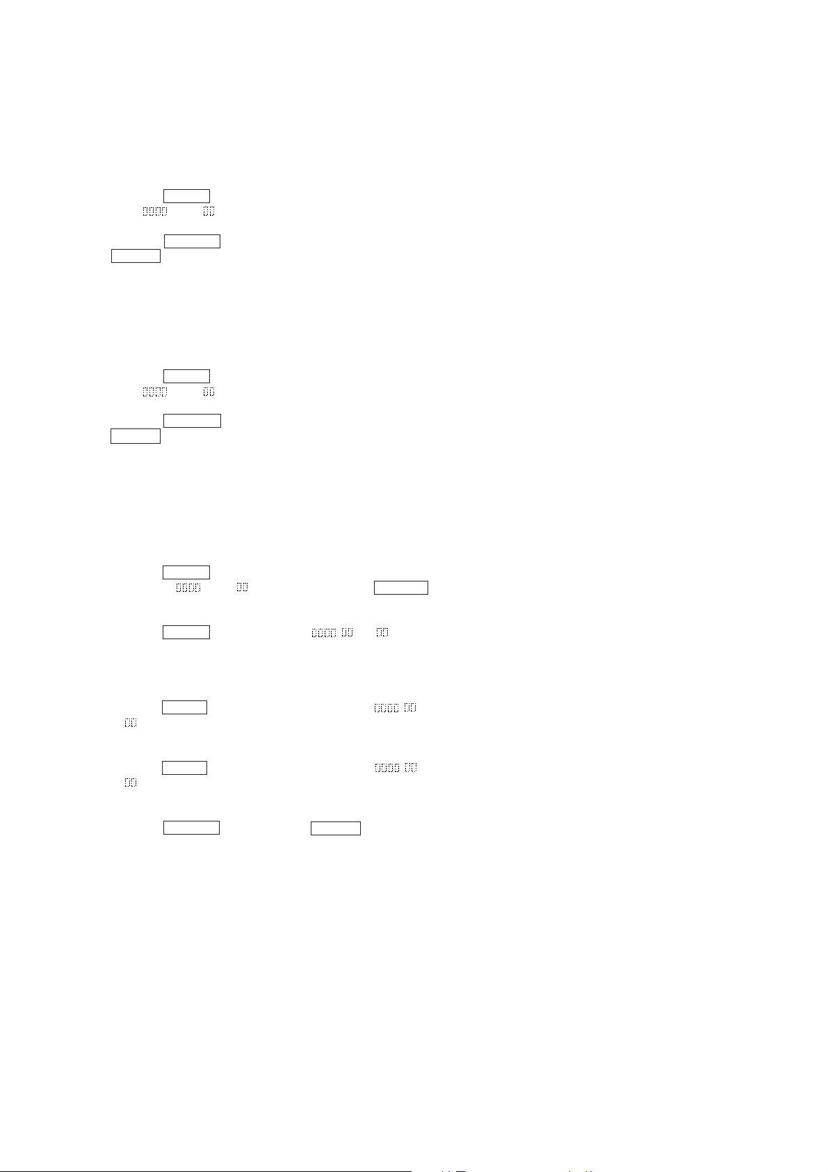
Note 1: T he following figure shows the relation between the C1 error
Note 2: As the C1 er ror rate changes, use the average value in the ad-
and focus bias value. Look for points a and b in the following
figure by the adjustment avove. The focus position (point c) is
automatically calculated from points a and b.
justment.
C1 error
about
200
Focus bias valu
(F. BIAS)
b
ca
Note 1: The data will be overwritten on the MO and erased when a re-
Note 2: If the traverse waveform is not clear, connect the oscilloscope as
corded disc is used in this adjustment.
shown in the following figure so that it can be seen more clearly.
Oscilloscope
330 k
BD (MD) board
TP69 (TEO)
TP1003 (VC)
Ω
10 pF
– 28 –
6-9. ERROR RATE CHECK
6-9-1. CD Error Rate Check
Checking Procedure :
1. Load a check disc (MD) TDYS-1.
2. Press the [VOLUME+/–] button to display “CPLAY MODE”.
3. Press the p (CD) button to display “CPLAY MID”.
4. “C = AD = ” is displayed.
5. Check that the C1 error rate is below 20.
6. Press the ^ (CD) button to stop playback. Then press the
6 (MD) button, and remove the check disc (MD).
6-9-2. MO Error Rate Checking
Checking Procedure :
1. Load a continuously recorded disc (Refer to 6-4. Creating the
Continuously Recorded Disc”).
2. Press the [VOLUME+/–] button to display “CPLAY MODE”.
3. Press the p (CD) button to display “CPLAY MID”.
4. “C = AD = ” is displayed.
5. Check that the C1 error rate is below 50 and ADER is 00.
6. Press the ^ (CD) button to stop playback. Then press the
6 (MD) button, and remove the disc.
6-10. FOCUS BIAS CHECK
Change the focus bias value and check the focus tolerance amount.
Checking Procedure :
1. Load a continuously recorded disc (Refer to 6-4. Creating the
Continuously Recorded Disc”).
2. Press the [VOLUME+/–] button to display “CPLAY MODE”.
3. Press the p (CD) button to display “CPLAY MID”.
4. When “C = AD = ” is displayed, press the ^ (CD)
button.
5. Press the [VOLUME+/–] button to display “FBIAS CHECK”.
6. Press the p (CD) button to display “ / c = ”.
The first four digits indicate the C1 error, the two digits after
the “/” indicate ADER and the two digits after “c =” indicate
the focus bias value.
Check that the C1 error is below 50 and ADER is 00.
7. Press the p (CD) button to change the display to “ / b
= ”.
Check that the C1 error does not drop below about 200 and
ADER does not remain above 00.
8. Press the p (CD) button to change the display to “ / a
= ”.
Check that the C1 error does not drop below about 200 and
ADER does not remain above 00.
9. Press the ^ (CD) button, press the 6 (MD) button next,
and remove the continuously recorded disc.
Note 1: If the C1 error is above about 200 or ADER is above 00 only for
point a (step 8 above) and point b (step 7 above), the focus bias
may not adjusted properly. In this case, adjust again.
– 29 –
 Loading...