

HCD-M10
SERVICE MANUAL
Ver. 1.3 2005.02
HCD-M10 is the Amplifier, MD deck, CD
player, Tape player and Tuner section in
CMT-M100MD.
Model Name Using Similar Mechanism HCD-J300
CD
Section
MD
Section
Tape deck
Section
CD Mechanism Type CDM55A1-K4BD43
Base Unit Type BU-K4BD43
Optical Pick-up Type KSM-213DHAP
Model Name Using Similar Mechanism HCD-C5
MD Mechanism Type MDM-7B4M
Optical Pick-up Type KMS-260E
Model Name Using Similar Mechanism HCD-J300
Tape Transport Mechanism Type Mech deck
AEP Model
UK Model
E Model
Australian Model
Amplifier section
European model:
DIN power output (Rated):10 +10 watts
(6 ohms at 1 kHz,DIN)
Continuous RMS power output (Reference):
15 +15 watts
(6 ohms at 1 kHz,10% THD)
Music power output (Reference):
25 +25 watts
Other models:
DIN power output (Rated):10 +10 watts
(6 ohms at 1 kHz,DIN)
Continuous RMS power output (Reference):
15 +15 watts
(6 ohms at 1 kHz,10% THD)
Inputs
ANALOG IN (phono jacks):
voltage 250 mV,
impedance 47 kilohms
SPECIFICATIONS
DIGITAL OPTICAL IN (Supported sampling
frequencies:32 kHz,44.1 kHz and 48 kHz)
Outputs
PHONES (stereo minijack):
accepts headphones of
16 ohms or more.
SPEAKER: accepts impedance of 6 to
16 ohms.
CD player section
System Compact disc and digital
audio system
Laser Semiconductor laser
(λ =780 nm)
Emission duration:
continuous
Frequency response 2 Hz – 20 kHz (±0.5 dB)
— Continued on next page —
MICRO HI-FI COMPONENT SYSTEM
9-873-570-04
2005B02-1
© 2005.02
Sony Corporation
Personal Audio Group
Published by Sony Engineering Corporation

HCD-M10
MD deck section
System MiniDisc digital audio
Laser Semiconductor laser
Sampling frequency 44.1 kHz
Frequency response 5 Hz – 20 kHz (±0.5 dB)
Tape deck section
Recording system 4-track 2-channel stereo
Frequency response 50 – 13,000 Hz (±3 dB),
Tuner section
FM stereo,FM/AM superheterodyne tuner
FM tuner section
Tuning range 87.5 – 108.0 MHz
Aerial FM lead aerial
Aerial terminals 75 ohms unbalanced
Intermediate frequency 10.7 MHz
AM tuner section
Tuning range
European model: 531 – 1,602 kHz
Other models: 531 – 1,602 kHz
Aerial AM loop aerial
Intermediate frequency 450 kHz
system
(λ =780 nm)
Emission duration:
continuous
using Sony TYPE I
cassettes
(50 kHz step)
(with the interval set at
9 kHz)
(with the interval set at
9 kHz)
530 – 1,710 kHz
(with the interval set at
10 kHz)
External aerial terminals
General
Power requirements
European model: 230 V AC,50/60 Hz
Other models: 220 – 240 V AC,,
Power consumption
European model: 55 watts
Other models: 55 watts
Dimensions (w/h/d)incl.projecting parts and controls
Mass Approx.4.9 kg
Design and specifications are subject to change without notice.
50/60 Hz
0.5 watts (at the Power
Saving mode)
Approx.159 x 216.5 x
330 mm
2
HCD-M10
C14/Toc Error
The MD deck cannot read the disc information
properly.
Replace the MD.
Erase all the recorded contents of the MD using
the All Erase Function (see page 36).
C41/Cannot Copy
The sound source is a copy of a commercially
available music software.
The Serial Copy Management System prevents
making a digital copy (see page 57).
Messages
One of the following messages may appear or
flash in the display during operation.
MD
Assign None
All the tracks on an MD are registered into groups.
Auto Cut
The MD deck is pausing the recording because
silence continued for 30 seconds or more during
digital recording.
Blank Disc
The inserted recordable MD is new, or all tracks on
the MD have been erased.
Cannot Edit
• A pre-mastered MD is in the deck.
• You tried to edit in Programme or Shuffle Play
mode.
Cannot REC
• A pre-mastered MD is in the deck.
• The function is switched to MD.
Cannot SYNC!
• There is no disc in the MD deck, or the MD is
protected against erasure.
• There is no time remaining on the MD.
continued
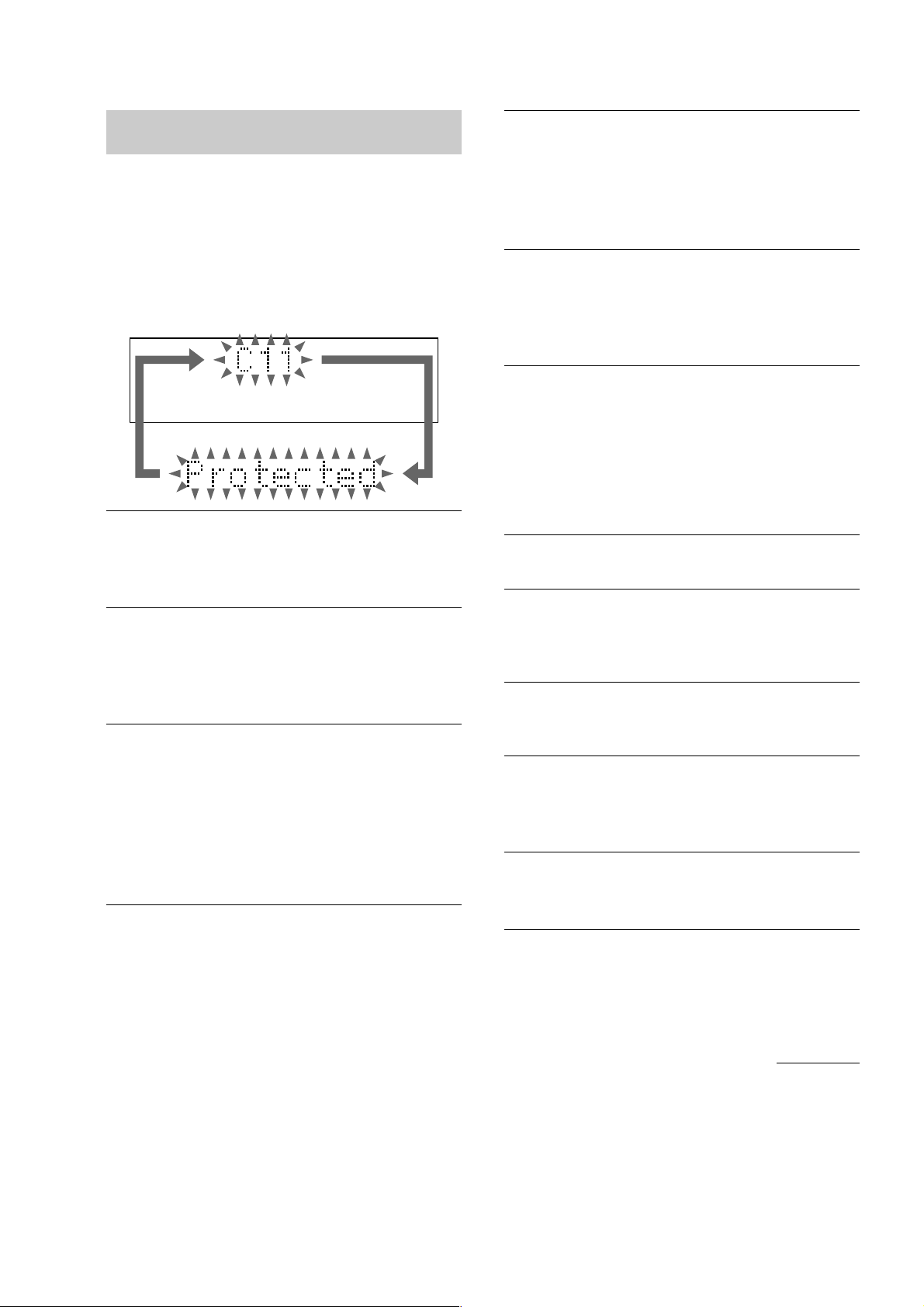
Self-diagnosis display
This system has a Self-diagnosis display
function to let you know if there is a system
malfunction. The display shows a code made
up of three letters and a message alternately to
show you the problem. To solve the problem
refer to the following list. If any problem
persists, consult your nearest Sony dealer.
C11/Protected
The MD is protected against erasure.
t
t
t
t
t
t
t
t
Remove the MD and slide the tab to close the
slot (see page 20).
C12/Cannot Copy
You tried to record a CD or MD with a format that
the system does not support, such as a CD-ROM.
Remove the disc and turn off the system once,
then turn it on again.
C13/REC Error
Recording could not be performed properly.
Move the system to a stable place, and start
recording over from the beginning.
The MD is dirty or scratched, or the MD does not
meet the standards.
Replace the MD and start recording over from
the beginning.
C13/Read Error
The MD deck cannot read the disc information
properly.
Remove the MD once, then insert it again.
3

HCD-M10
Self-diagnosis display (continued)
Complete!
The editing operation of MDs is completed.
Disc Full!
There is no time remaining on the MD.
Eject
The MD deck is ejecting the MD.
Group Full!
An attempt was made to create a new group in
excess of the maximum number of groups, or there
are insufficient characters for updating the group
management information.
Impossible
• You tried to make an impossible editing
operation.
• You cannot combine or erase the tracks due to
the system limitations of MDs.
• You cannot specify the division point at the
beginning or end of a track.
Incomplete!
Adjustment of the recording level after recording
or Fade-in and Fade-out procedures have failed
since the system was either subject to vibration or
there is a damaged or dirty disc in the tray. Place
the system in a stable place to minimize shock and
vibration. Do not use damaged or dirty discs.
Step Full!
You tried to programme 26 or more tracks (steps).
Push STOP!
You pressed PLAY MODE/DIRECTION (or
PLAY MODE on the remote) during play.
—Rehearsal—
The MD is playing the specified dividing point for
confirmation during the A-B Erase Function and
the Divide Function.
S.F Edit!
You attempted to perform another operation while
in S.F Edit (changing the recording level after
recording, Fade-in, Fade-out) mode.
S.F Edit NOW
You pressed =/1 while in S.F Edit (changing the
recording level after recording, Fade-in, Fade-out)
mode.
Smart Space
The signal was input again after silence continued
for 3 or more but less than 30 seconds during
digital recording.
Text Protect
There is CD TEXT information which cannot be
recorded on the MD.
TOC Reading
The MD deck is reading the TOC information of
the MD.
Initialize
The power was off for a long time, so the system is
initializing itself.
Name Full
There is no more space to store track, disc or group
titles.
No Change
While attempting to change the recording level
after recording, you pressed ENTER/YES without
actually changing the recording level, so no change
was made.
No Disc
There is no disc in the MD deck.
OVER
You have reached the end of the MD while
pressing M during playing pause.
TOC Writing
The MD deck is writing the information of
recorded or edited contents.
Track End
You have reached the end of the track while
adjusting the dividing point during the Divide
Function.
Tr Protect
You attempted to erase a protected track.
4

TABLE OF CONTENTS
HCD-M10
CD
Cannot Edit
You tried to label a CD TEXT disc.
CD No Disc
There is no CD in the player.
Complete!
The editing operation of CD is completed.
Name Full
There are already 50 disc titles stored in the
system.
OVER
You have reached the end of the CD while
pressing M during play or pause.
Step Full!
You tried to programme 26 or more tracks (steps).
TAPE
Cannot SYNC!
There is no tape in the tape deck, or the tab has
been removed from the cassette.
No Tab
You cannot record the tape because the tab has
been removed from the cassette.
No Tape
There is no tape in the tape deck.
1. SERVICING NOTES ······················································ 6
2. GENERAL ········································································ 10
3. DISASSEMBLY ······························································ 12
4. TEST MODE··································································· 22
5. ELECTRICAL ADJUSTMENTS······························ 27
6. DIAGRAMS
6-1. CIRCUIT BOARDS LOCATION ····································· 41
6-2. BLOCK DIAGRAM – CD BOARD – ······························ 42
BLOCK DIAGRAM – MD BOARD – ····························· 43
BLOCK DIAGRAM – MAIN BOARD – ························· 44
BLOCK DIAGRAM – PANEL BOARD – ······················· 45
6-3. PRINTED WIRING BOARD – CD BOARD – ················ 46
6-4. SCHEMATIC DIAGRAM – CD BOARD – ····················· 47
6-5. PRINTED WIRING BOARD – BD BOARD – ················ 48
6-6. SCHEMATIC DIAGRAM – BD BOARD (1/2) – ············ 49
6-7. SCHEMATIC DIAGRAM – BD BOARD (2/2) – ············ 50
6-8. SCHEMATIC DIAGRAM – MAIN OARD (1/2) – ··········51
6-9. SCHEMATIC DIAGRAM
– MAIN BOARD (2/2), LOADING BOARD – ················ 52
6-10.PRINTED WIRING BOARD
– MAIN BOARD,LOADING BOARD – ························· 53
6-11.PRINTED WIRING BOARD – MD DIGITAL BOARD –54
6-12.SCHEMATIC DIAGRAM – MD DIGITAL BOARD – ··· 55
6-13.PRINTED WIRING BOARD – TC BOARD – ················ 56
6-14 SCHEMATIC DIAGRAM – TC BOARD – ····················· 57
6-15.
PRINTED WIRING BOARDS
– PANEL BOARD, BL (AMBER), BL (WHITE),
JACK BOARD –
6-16 SCHEMATIC DIAGRAM
– PANEL BOARD, BL (AMBER), BL (WHITE),
JACK BOARD –
6-17.PRINTED WIRING BOARD
– AMP BOARD, POWER BOARD – ······························ 60
6-18.SCHEMATIC DIAGRAM – AMP BOARD – ·················· 61
6-19.SCHEMATIC DIAGRAM – POWER BOARD – ············ 62
6-20.IC PIN FUNCTION DESCRIPTION································63
······························································ 58
······························································ 59
7. EXPLODED VIEWS ····················································· 72
8. ELECTRICAL PARTS LIST·····································80
SAFETY-RELATED COMPONENT WARNING!!
COMPONENTS IDENTIFIED BY MARK 0 OR DOTTED LINE WITH
MARK 0 ON THE SCHEMATIC DIAGRAMS AND IN THE PARTS
LIST ARE CRITICAL TO SAFE OPERATION. REPLACE THESE
COMPONENTS WITH SONY PARTS WHOSE PART NUMBERS
APPEAR AS SHOWN IN THIS MANUAL OR IN SUPPLEMENTS
PUBLISHED BY SONY .
5
HCD-M10
Ver 1.2 2002.05
SECTION 1
SERVICING NOTE
NOTES ON HANDLING THE OPTICAL PICK-UP
BLOCK OR BASE UNIT
The laser diode in the optical pick-up block may suffer electrostatic
break-down because of the potential difference generated by the
charged electrostatic load, etc. on clothing and the human body.
During repair, pay attention to electrostatic break-down and also
use the procedure in the printed matter which is included in the
repair parts.
The flexible board is easily damaged and should be handled with
care.
FOR CD
NOTES ON LASER DIODE EMISSION CHECK
The laser beam on this model is concentrated so as to be focused on
the disc reflective surface by the objective lens in the optical pickup block. Therefore, when checking the laser diode emission,
observe from more than 30 cm away from the objective lens.
FOR MD
NOTES ON LASER DIODE EMISSION CHECK
Never look into the laser diode emission from right above when
checking it for adjustment. It is feared that you will lose your sight.
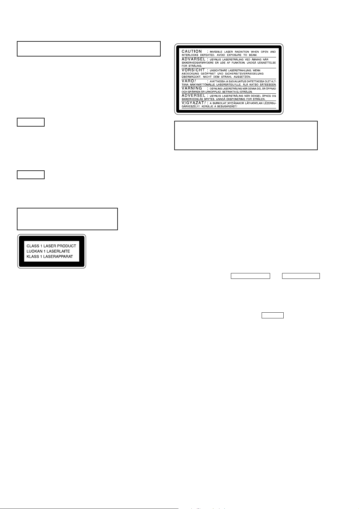
Laser component in this product is capable
of emitting radiation exceeding the limit for
Class 1.
This caution
label is
located inside
the unit.
CAUTION
Use of controls or adjustments or performance of procedures
other than those specified herein may result in hazardous radiation
exposure.
Notes on chip component replacement
• Never reuse a disconnected chip component.
• Notice that the minus side of a tantalum capacitor may be
damaged by heat.
Note for Speaker Terminals
The negative speaker outputs are not grounded bevause of the
balanced transformerless circuit.
(If connecting them to ground, or each other, the circuit is broken)
This appliance is classified as a CLASS 1 LASER product. The
CLASS 1 LASER PRODUCT MARKING is located on the rear
exterior.
• DISC TRAY LOCK
The disc tray lock function for the antitheft of an demonstration
disc in the store is equipped.
Releasing Procedure :
1. Press two buttons of ENTER/START and OPEN/CLOSE
(CD section) simultaneously.
2. The message “UNLOCKED” is displayed and the tray is
unlocked.
Note : When “LOCKED” is displayed, the tray lock is not released
by turning power on/off with the POWER button.
6
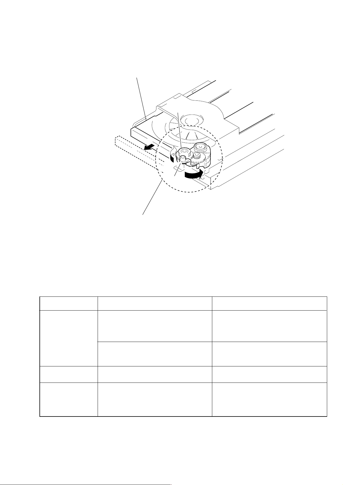
DRAWING OUT THE TRAY DURING POWER OUT
• Perform after removing front panel.
tray
B
HCD-M10
gear(B)
cam block
First turn the whole of cam block in the arrow
then put out tray by turning gear (B) in the arrow
A
A
direction with fingers,
B
direction.
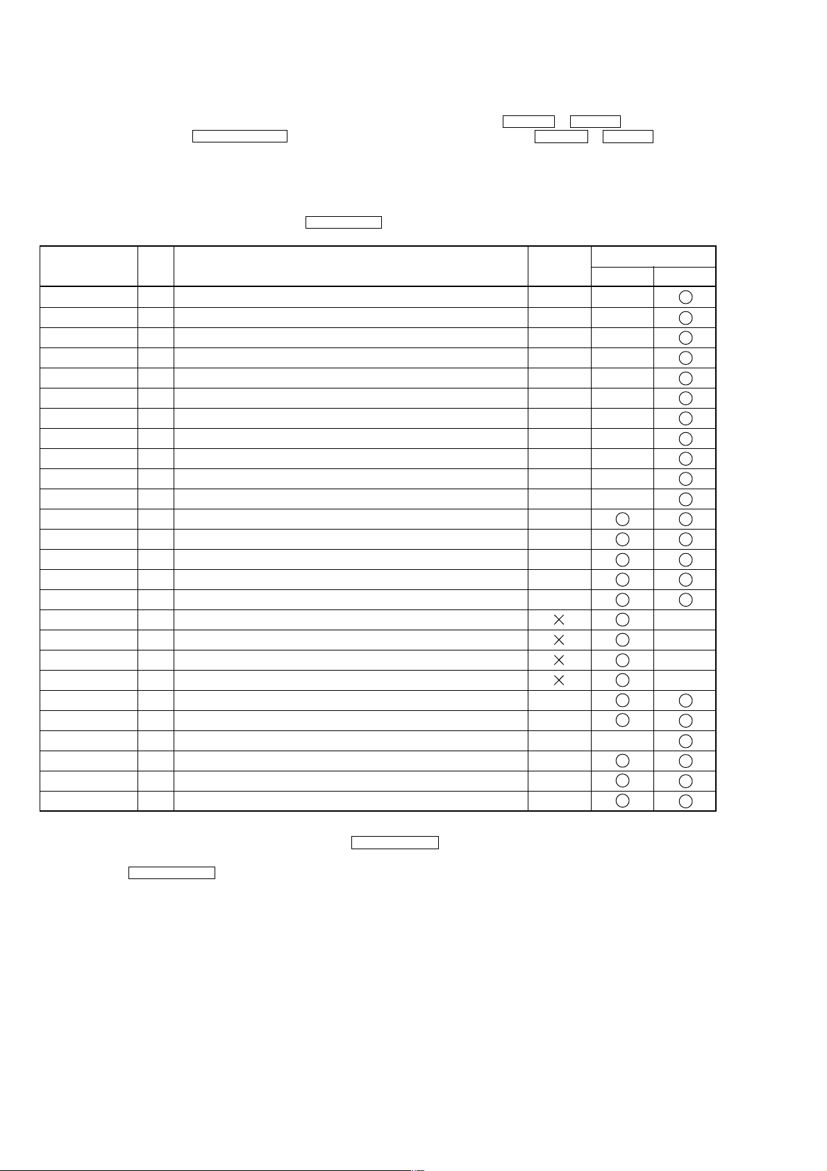
CHECKS PRIOR TO PARTS REPLACEMENT AND ADJUSTMENTS IN MD
Before performing repairs, perform the following checks to determine the faulty locations up to a certain extent.
Details of the procedures are described in “Section 5 Electrical Adjustments”.
Laser power check
(6-2 : See page 33)
Auto check
(6-4 : See page 34)
Temperature
compensation
offset check
(6-1 : See page 33)
Criteria for Determination
(Unsatisfactory if specified value is not satisfied)
• 0.9 mW power
Specified value : 0.80 to 0.96 mW
• 7.0 mW power
Specified value : 6.8 to 7.2 mW
Iop (at 7.0mW)
• Labeled on the optical pick-up
Iop value ± 10mA
• Unsatisfactory if displayed as “NG : XXXX”NG
(XXXX are arbitrary numbers)
• Unsatisfactory if displayed as “T=@@ (##) [NG]”
NG
(@@, ## are both arbitrary numbers)
• Clean the optical pick-up
• Adjust again
• Replace the optical pick-up
• Replace the optical pick-up
• Replace the optical pick-up
• Check for disconnection of the circuits around
D101 (BD board)
• Check the signals around IC101, IC151, CN102,
CN103 (BD board)
Measure if unsatisfactory
Note:
The criteria for determination above is intended merely to determine if satisfactory or not, and does not serve as the specified value for adjustments.
When performing adjustments, use the specified values for adjustments.
7
HCD-M10
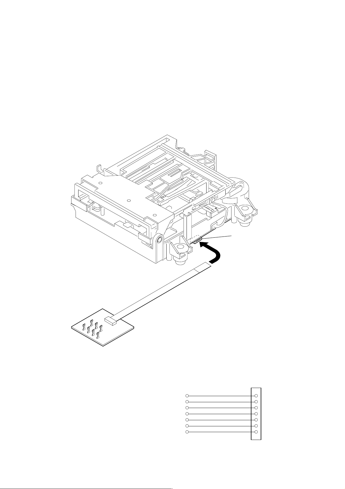
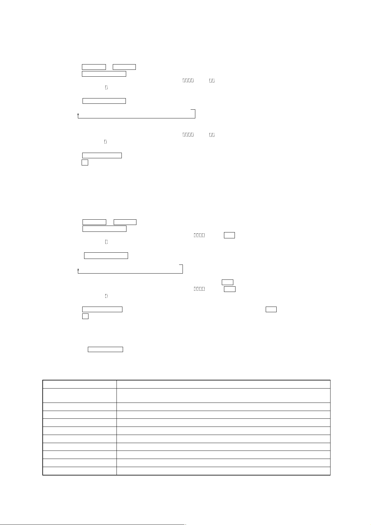
JIG FOR CHECKING BD (MD) BOARD WAVEFORM
The special jig (J-2501-196-A) is useful for checking the waveform of the BD (MD) board. The names of terminals and the checking items
to be performed are shown as follows.
GND : Ground
I+3V : For measuring Iop (Check the deterioration of the optical pick-up laser)
Iop : For measuring Iop (Check the deterioration of the optical pick-up laser)
TE : TRK error signal (Traverse adjustment)
VC : Reference level for checking the signal
RF : RF signal (Check jitter)
FE : Focus error signal
I+3V
GND
FE
RF
Iop
TE
VC
I+3V
Iop
GND
TE
FE
VC
RF
CN105
1
I+3V
Iop
GND
TE
FE
VC
RF
7
for
MDM-7B4M
8

CLEANING THE OPTICAL PICK-UP (CD PLAYER)
2
CD mechanism deck
Move it in the
5
direction of the arrow
B
.
HCD-M10
1
Floating screw
4
Rotate it in the
direction of the arrow A.
6
Clean the lens block
by cotton swab
Note 1:
In cleaning the lens, do not apply an excessive force
As the optical pick-up is vulnerable, application of
excessive force could damage the lens holder.
Note 2:
In cleaning, do not use a cleaner other than exclusive
cleaning liquid. (KK-91 or isopropyl alcohol)
Note 3:
Wipe the obujective lens spirally from center toward
outside. (See Figure A)
B
3
BU-K4BD43
A
Optical pick-up
(FIGURE A)
9
HCD-M10
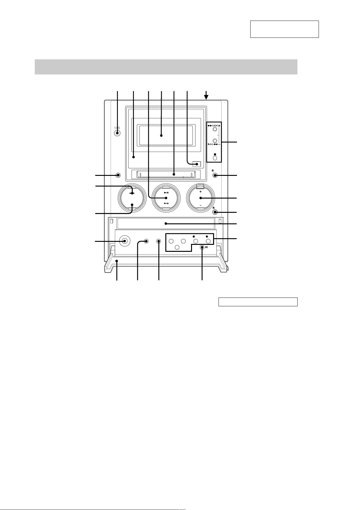
Main unit
SECTION 2
GENERAL
This section is extracted
from instruction manual.
wa
w;
ql
qk
1
2
3
4
67
5
8
9
0
qa
qs
qd
CD disc tray qs (9)
CD NX 3 (9, 11)
Cover qj
Display window 4
ENTER/START qd ( 22, 24, 46,
47)
FM MODE qg (44)
FUNCTION wa (9, 11, 13, 15, 17,
18, 21, 25, 26, 31–39, 41, 46,
48, 53)
GROUP indicator 2 (18, 21, 22,
32–34)
MD insertion slot 5
MD NX 3 ( 15, 17, 18, 21, 25)
qj
qh qg qf
PHONES jack qk
PLAY MODE/DIRECTION qh
(9, 11, 13, 15, 17, 24, 30,
46–48)
REC MODE qd (26)
Remote sensor 6
REPEAT qg ( 10, 16)
SYNCHRO MODE qd (22, 24,
46, 47)
TAPE nN w; ( 46–48)
TUNER BAND ql (43, 44)
TUNING MODE qh (43, 44)
TUNING +/– 8 (44)
VOLUME +/– 0
BUTTON DESCRIPTIONS
?/1 (power) 1 (8, 20, 30, 43,
44, 50, 52)
Z PUSH OPEN/CLOSE 7 (46)
m/M 8 (10, 16, 37, 39, 43,
44, 46)
l/L 8 (10, 11, 13,
16–18, 26, 31, 33–38, 40, 41,
43)
x 8 (10, 16, 21, 23–25, 29,
46–48)
Z MD 9 (15, 16, 20, 30)
Z CD qa (9, 10)
z MD qd (21, 25, 28, 40)
z TAPE qd (48)
X TAPE qf ( 46,
48)
10
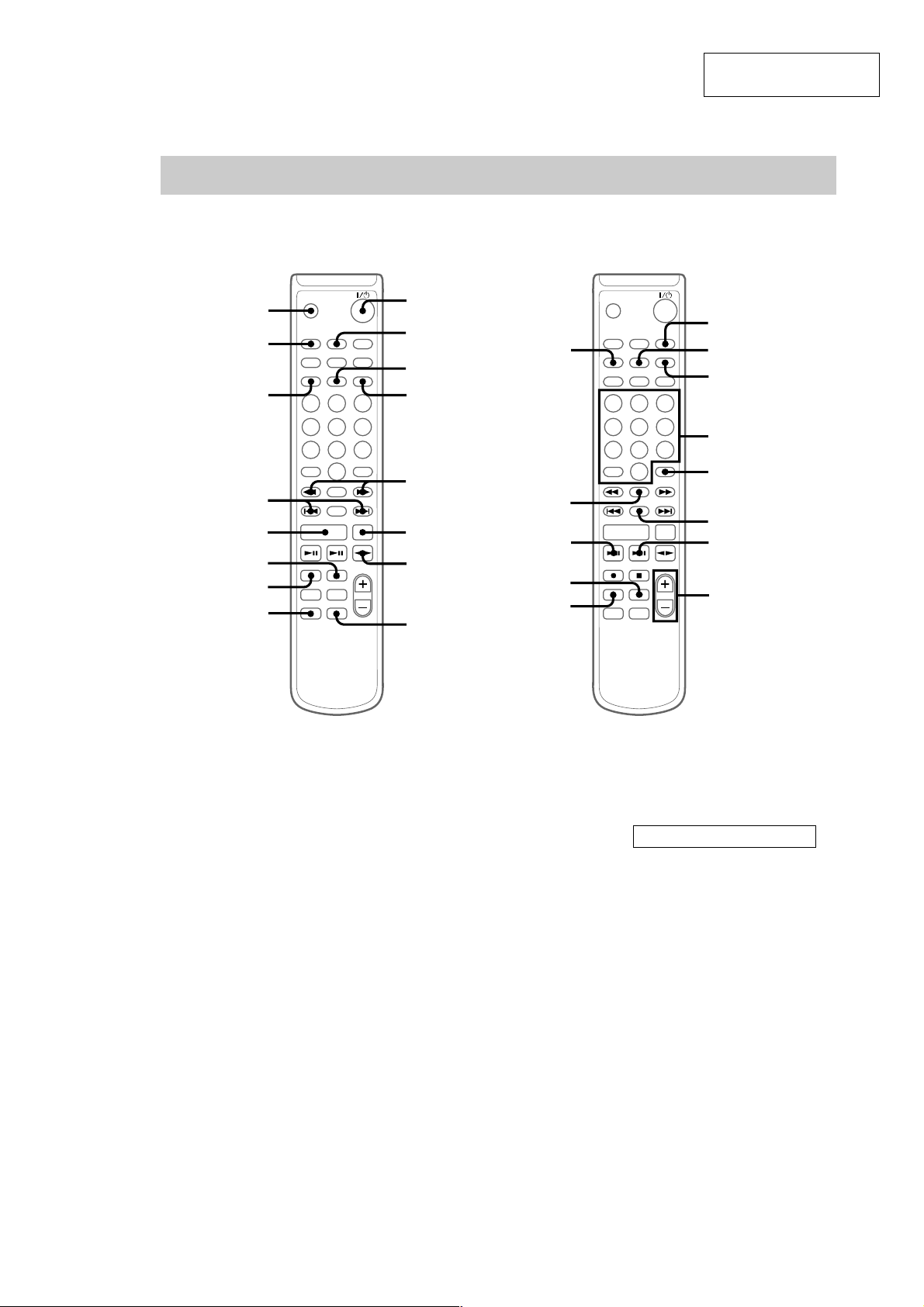
Remote Control
HCD-M10
This section is extracted
from instruction manual.
qh
qg
qf
qd
qs
qa
0
9
1
2
3
4
5
6
7
8
wl
wk
wj
wh
wg
qj
qk
ql
w;
wa
ws
wd
wf
BASS/TRE 8 (49)
CD NX wd (9, 11)
CLEAR wa (11, 13, 17, 31, 45)
CLOCK/TIMER SELECT qg
(50, 52)
CLOCK/TIMER SET 2 (8, 50,
51)
CURSOR T/t 5 (8, 13, 31)
DISPLAY ws (8, 11, 12, 17, 19,
21, 45)
DSG 9 (49)
ENTER/YES 4 (8, 11, 14, 17,
25, 26, 30, 33–35, 37, 38, 40,
41, 43, 45, 50, 51)
FM MODE qj (44)
FUNCTION qs (9, 11, 13, 15, 17,
18, 21, 25, 26, 31–39, 41, 46,
48, 53)
GROUP wl (18, 20, 22, 32–34)
GROUP SKIP qk (18, 22, 32, 34)
MD z 0 (21, 25, 28)
MD NX wj (15, 17, 18, 21, 25)
MENU/NO qf (14, 26, 30,
32–35, 37–41, 43)
NAME EDIT/SELECT 3 (13,
30, 32, 45)
Number buttons w; (10, 13, 16,
31, 44)
PLAY MODE wg (9, 11, 13, 15,
17, 30)
REPEAT wh (10, 16)
SCROLL wk (14, 19, 32, 33)
SLEEP qh (49)
TAPE nN 7 (46–48)
TUNER BAND 6 (43, 44)
TUNING MODE ql (43, 44)
VOL +/– wf
BUTTON DESCRIPTIONS
@/1 (power) 1 (8, 20, 30, 43,
44, 50, 52)
m/M 5 (10, 16, 37, 39, 43,
44, 46)
x qa (10, 16, 21, 23–25, 29,
46–48)
./> qd (8, 10, 11, 13,
16–18, 26, 31, 33–38, 40, 41,
43, 49–51)
(44)
–/+ qd
11
HCD-M10
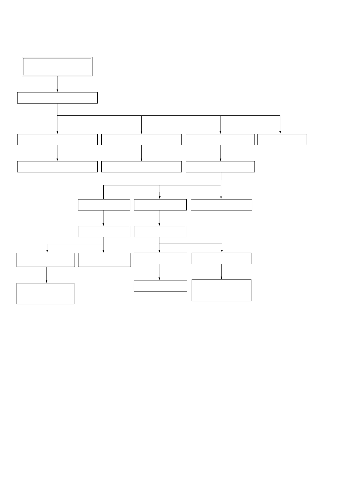
• The equipment can be removed using the following procedure.
SET
Case (R), Case (L)
SECTION 3
DISASSEMBLY
Front panel section
PANEL board, BL board, JACK board TC board, mechanism deck MAIN board, tuner
CD mechanism deck
Base unit (BU-K4BD43)
CD board, CD optical
pick-up block
(KSM-213DHAP)
Cam (CDM55),
LOADING board
Top cover section
Holder section
Over write head
OP-Sub section
Chassis section
AMP board, POWER boardMD mechanism deckMD DIGITAL board
BD board
Loading motor assembly,
spindle motor assembly,
sled motor assembly
Back panel
12
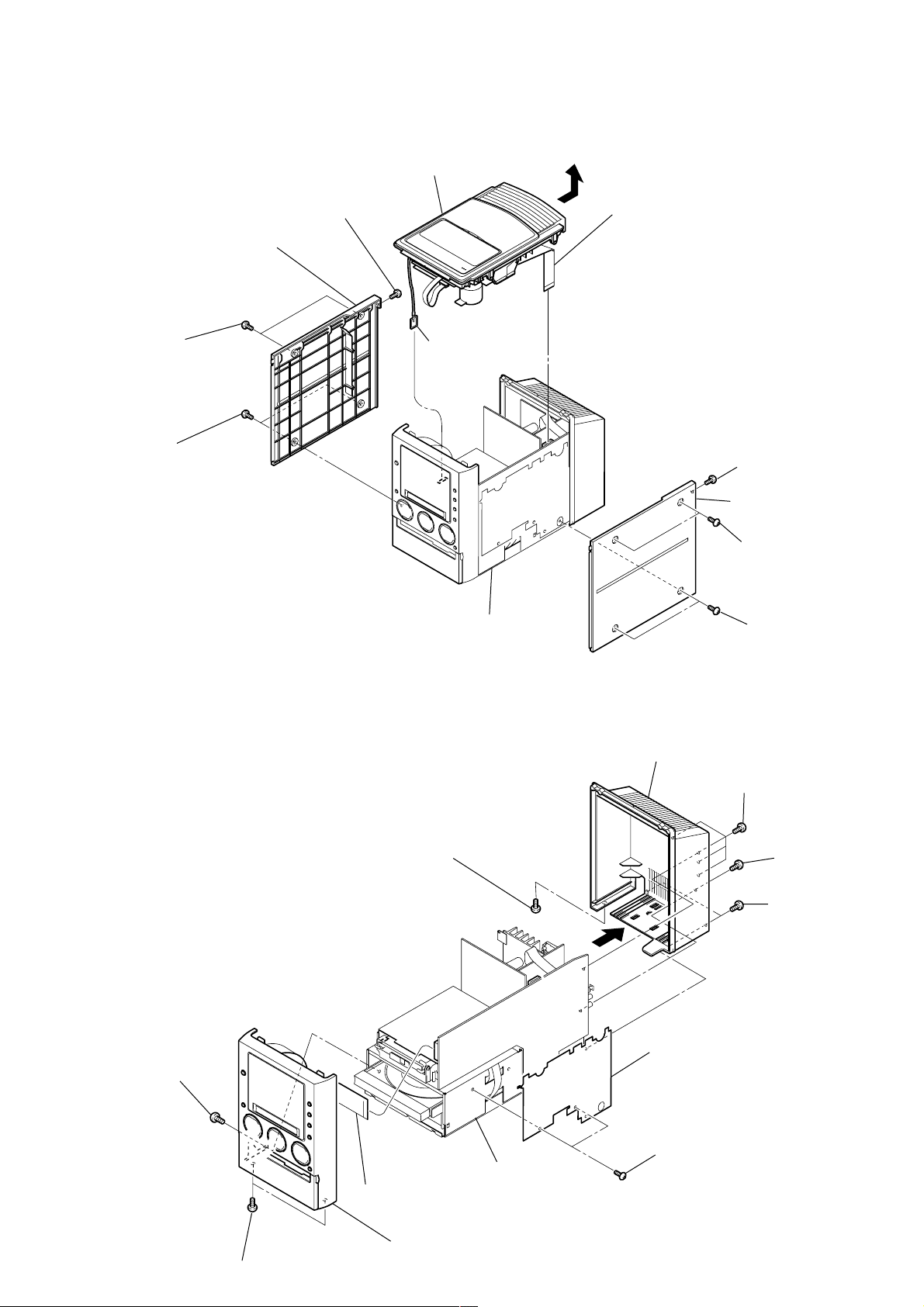
Note: Follow the disassembly procedure in the numerical order given.
)
6
Back panel
1
Four screws
(+BVTP3X10)
2
Screw
(+BVTP3X8)
7
Two screws (+BVTT3X6)
4
Screw (+BVTP3X10)
8
Shield plate (Micro Computer)
3
T wo screws
(+BVTP3X10)
9
Two screws (+BVTP3X10)
0
Screw (+BVTT3X6)
qs
Front panel section
Chassis section
qa
Wire (flat type) (CN500)
5
3-1. CASE (R), CASE (L), TOP COVER SECTION
qs
Top cover section
7
Screw (+BVTP 3X10)
8
Case (L)
9
6
Two screws (case 3 TP2)
5
Two screws (case 3 TP2)
Ground terminal
0
qa
Wire (flat type) (CN203)
HCD-M10
3
Screw (+BVTP3X10)
3-2. BACK PANEL, FRONT PANEL SECTION
Chassis section
4
Case (R)
2
Two screws (case 3 TP2)
1
Two screws (case 3 TP2
13
HCD-M10
)
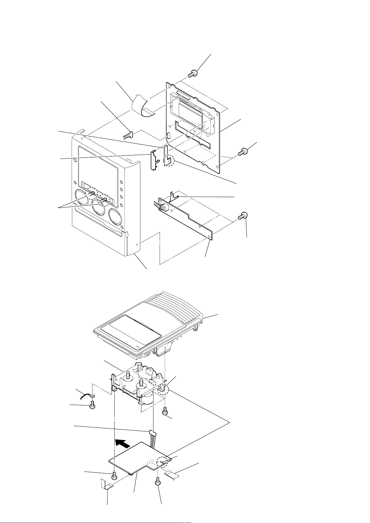
3-3. PANEL BOARD, BL BOARD, JACK BOARD
4
Wire (flat type) (CN501)
5
Connector (CN502)
9
BL board
7
Lid (LCD)
3
T wo claws
1
Two screws (+BVTP2.6X8)
6
8
T wo solderings
qa
Ground plate (HP)
PANEL board
2
Five screws (+BVTP2.6X8
3-4. TC BOARD, MECHANISM DECK
0
Mechanism deck
Ground lug
9
Screw (+BVTP3X8)
6
Connector
(mechanism deck 9 pins)
A
Front panel
qs
Hook
8
Three screws
(+BVTP3X8)
JACK board
Top cover
5
on mechanism deck by sliding TC board in
the arrow
0
Four screws
(+BVTP2.6X8)
Remove a crack of TC board from a hook
A
direction.
14
4
Screw (+BVTP3X8)
7
TC board
2
Wire (flat type) (CN1002)
Crack
3
Screw (+BVTP3X8)
1
Wire (flat type) (CN1001)

3-5. MAIN BOARD, TUNER
0
Wire (flat type) (15 core)
qs
Tuner
qa
Screw (+BVTP3X8)
4
Screw (+BVTT3X6)
3
Screw (+BVTT3X6)
2
Connector
(CN202)
7
Wire (flat type) (CN102)
8
Wire (flat type) (CN103)
9
Connector (CN101)
qd
MAIN board
1
Wire (flat type) (CN903)
6
Wire (flat type) (CN105)
5
7
Connector of power cord (CN991)
Ground lug
6
Connector (CN992)
5
Connector (CN993)
9
POWER board
4
AMP board
8
Two screws (+BVTT3X6)
2
Two screws (+BVTP3X10)
3
Board to board connector (CN900-CN901)
1
Screw (+BVTT3X6)
HCD-M10
3-6. AMP BOARD, POWER BOARD
15
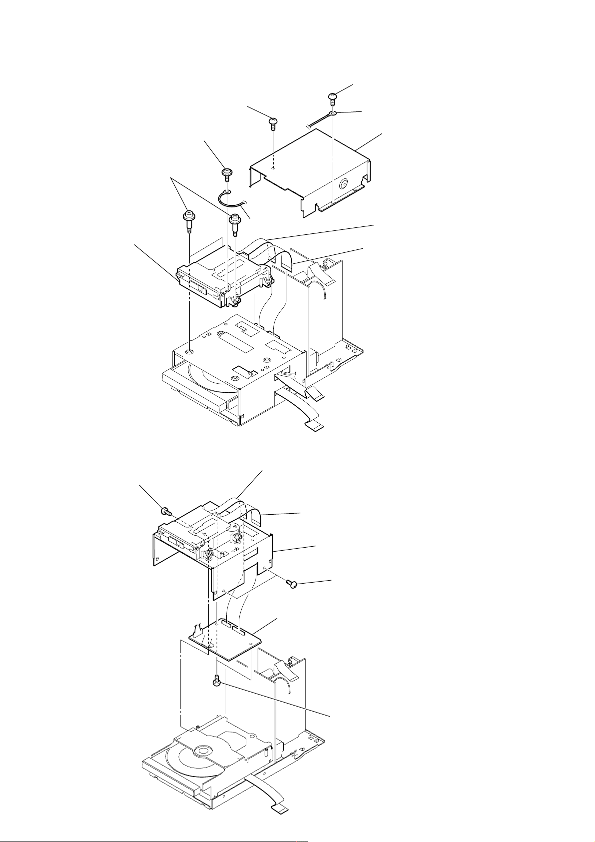
HCD-M10
)
3-7. MD MECHANISM DECK
4
7
Four step screws (+BVTTWH M3)
8
MD mechanism deck
1
Screw (+BVTT3X6)
Screw (+BTN1.7X3)
Ground lug
2
Screw (+BVTT3X6)
Ground lug
3
Shield (MDM)
6
Wire (flat type) (CN703)
5
Wire (flat type) (CN702)
3-8. MD DIGITAL BOARD
4
Screws (+BVTT3X6)
2
Wire (flat type) (CN703)
1
Wire (flat type) (CN702)
5
Bracket (MDM)
3
7
MD DIGITAL board
6
Two screws (+BVTT3X6
Two screws (+BVTT3X6)
16
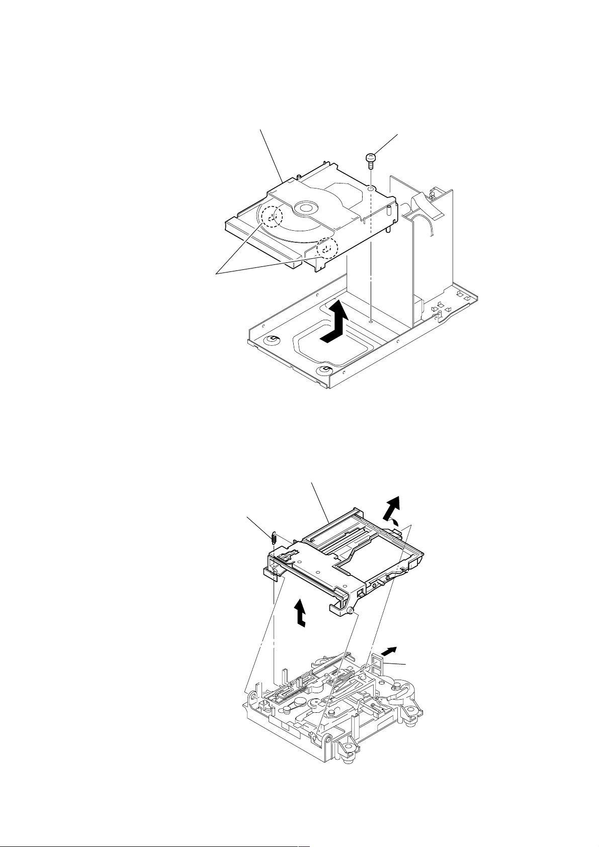
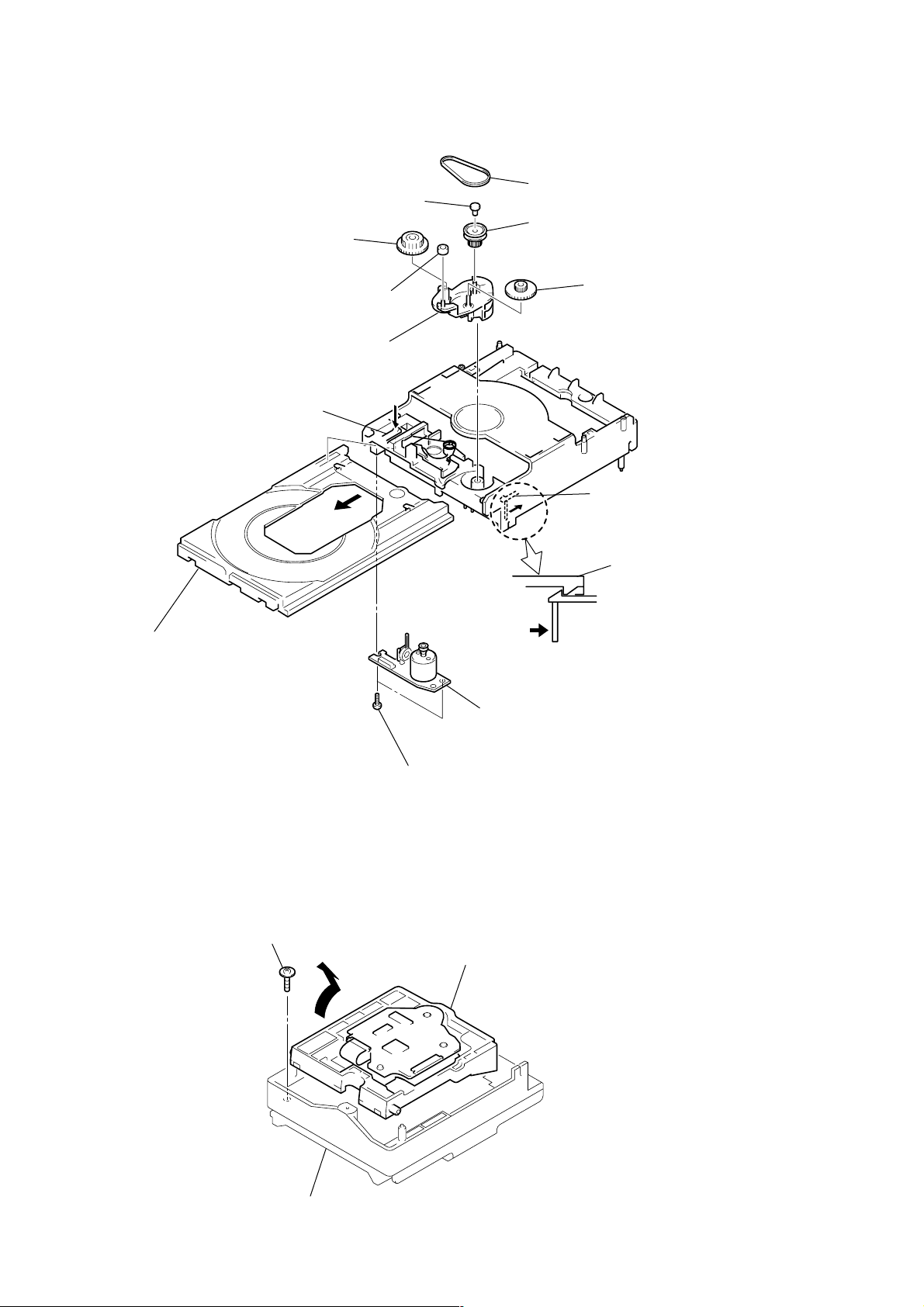
3-9. CD MECHANISM DECK
k
2
Two hooks
4
CD mechanism deck
1
Screw (+BVTT3X6)
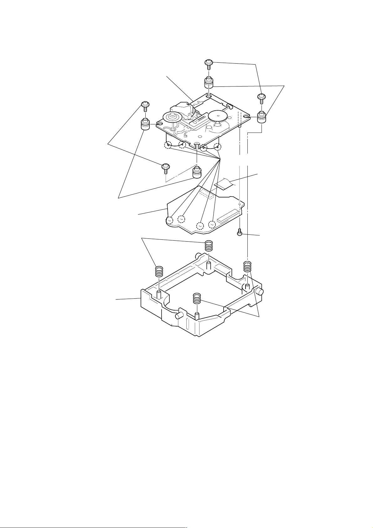
HCD-M10
3-10. HOLDER SECTION
1
Tension spring (holder)
5
Holder section
4
3
3
2
Hoo
17

HCD-M10
3-11. BD BOARD
2
Remove two solderings
(spindle motor)
1
Remove two solderings
(sled motor)
6
Flexible board (CN101)
5
Two screws (+BP TRI 2X6 CZN)
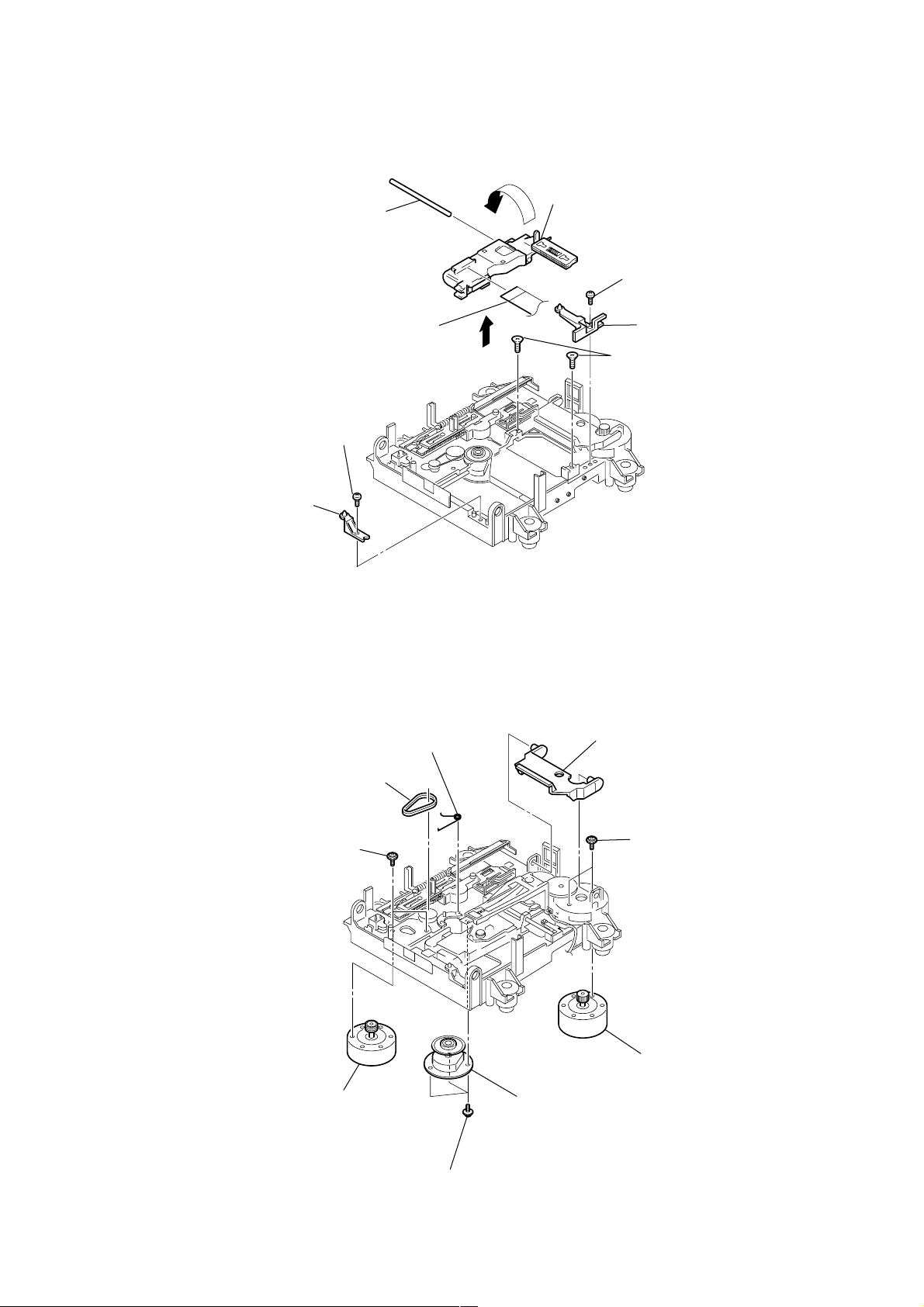
3-12. OVER WRITE HEAD (HR901)
8
BD board
7
Connector (CN104)
3
Remove two
solderings
(loading motor)
M702
M701
M703
S102
4
Remove three solderings
(switch)
2
Over write head
(HR901)
1
Screw (P1.7X6)
18
3-13. OP SUB SECTION
)
1
Screw (+BP TRI 2X6 CZN)
6
Main shaft
8
Flexible board
7
9
OP sub section
5
3
Screw (+BP TRI 2X6 CZN
4
Base (BU-A)
Base (BU-A)
HCD-M10
2
Base (BU-D)
3-14. LOADING MOTOR ASSEMBLY, SPINDLE MOTOR ASSEMBLY, SLED MOTOR ASSEMBLY
1
Lever (head)
8
Two screws (+PWH1.7X3.5)
4
Two screws (+PWH1.7X3.5)
3
Torsion spring (CLV)
2
Belt (loading)
5
Loading motor assembly (M103)
7
Spindle motor assembly (M101)
6
Three tapping screws (M1.7)
9
Sled motor assembly (M102)
19
HCD-M10
3-15. CAM (CDM55), LOADING BOARD
8
Gear (B)
5
Spacer (55)
7
Roller
q;
Cam (CDM55)
4
Belt (CDM55)
6
Pulley (LDG)
9
Gear (A)
3
Pull out the tray.
2
Push the claw in the
direction of the arrow
C
A
C
.
1
Pull out the tray in the direction
qs
qa
Two screws (+BTP2.6X6)
B
B
LOADING board
Release the lock
of the arrow
While pushing this claw in the
direction of the arrow B, release
the lock.
A
.
3-16. BASE UNIT (BU-K4BD43)
Floating screw (+PTPWHM2.6)
1
20
3
Chassis (F)
A
2
Remove the base unit (BU-K4BD43)
in the direction of the arrow
A
.
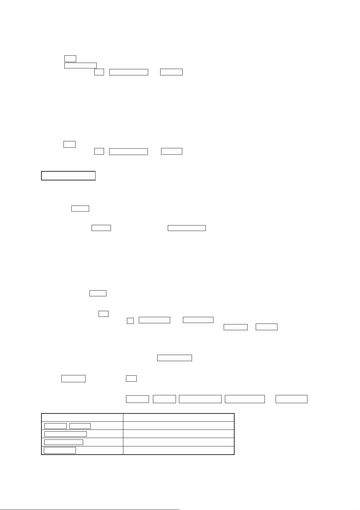
3-17. CD BOARD, CD OPTICAL PICK-UP (KSM-213DHAP)
qs
Optical pick-up (KSM-213DHAP)
7
Two insulators
8
Two insulators
5
Two compression springs
6
Two compression springs
qa
CD board
4
Holder (213D)
3
Two floating screws
(+PTPWHM2.6)
2
Two floating screws (+PTPWHM2.6)
1
Wire (flat type) (CN102)
q;
Remove the four solderings from the bottom.
9
Screw (+BTP2.6X6)
HCD-M10
21

HCD-M10
SECTION 4
TEST MODE
Note 1:About “R”
As this unit has only a few buttons, some operations require the use of remote commander (RM-SM100E/provided with unit) buttons. These
operations are indicated as “R” in this manual.
Example: MENU/NO “R” ...Press the [MENU/NO] button of the remote commander.
Note 2:Incorrect operations may be performed if the test mode is not entered properly.
In this case, press the ?/1 button to turn the power off, and retry to enter the test mode.
[STR TEST MODE]
1. Cold Reset
• The cold reset clears all data including preset data stored in the RAM to initial conditions. Execute this mode when returning the set to
the customers.
Procedure:
1. Press ?/1 button to turn the power on.
2. Press three buttons x , ENTER/START and ?/1 simultaneously.
3. The memory is reset, the power turns off and the DEMO program starts.
2. Panel Test Mode
• This mode is used to check the software version, LCD, LED and keyboard.
Procedure:
1. Press three bottons x , ENTER/START and FUNCTION simultaneously.
2. LEDs and LCD are all turned on.
2-1. Version check
1. When entering the software version display mode, press REPEAT butto .The model name (“M100”) and destination are displayed.
2. Each time REPEAT button is pressed, the display changes MC, GC, CD, CDD, CDMA,CDMB, BDA, BDB, ST, TA, TM, TC and
MD (returns to MC) in this order, and returns to the top of the version display.
3. When REC MODE button is pressed while the version numbers are being displayed, year, month and day of the software creation
appear. When REC MODE button is pressed again, the display returns to the software version display. When REPEAT button is
pressed while year, month and day of the software creation are being displayed, the year , month and day of creation of the sof tware
versions are displayed in the same order of version display.
2-2. Key check
1. Press PLAYMODE button, and the key check mode is activated. In the key check mode, the LCD displays “K 0 J 0 V 0”. Each time
a button is pressed, “K 0” value increases. However, once a button is pressed, it is no longer taken into account. It is end at “K21J 0V
0”
2. To exit from this mode, press three buttons in the same manner as step 1, or disconnect the power cord.
3. Common Test Mode
Procedure:
1. Press ?/1 button to turn the power on.
2. Press three buttons x , ENTER/START and TAPE nN simultaneously.
3. The set goes to the key test mode and the MD and TAPE segments flash.
3-1. Amp Test Mode
1. In the common test mode, every time you press BASS/TRE “R” button, the following items changes in the order as shown below.
BASS/TRE MAX, VOL MAX
BASS/TRE MIN, VOL MAX
BASS/TRE FLAT, VOL MAX
2. When VOLUME + button or VOLUME + “R” button is pressed, VOLUME goes MAX.
3. When VOLUME – button or VOLUME – “R” button is pressed, VOLUME goes MIN.
4. To exit from this mode, press ?/1 button and disconnect the power cord.
3-2. Tape Test
1. Check the set is in the common test mode.
2. Insert a recordable cassette tape.
3. Play back the recorded MD.
4. Press z TAPE button.
5. Select the recording direction with TAPE nN button.
6. Press X TAPE button to start recording.
7. When m “R” or M “R” button against the tape recording direction is pressed, the tape returns to the recording started point
and the set starts playback.
8. To exit from this mode, press ?/1 button and disconnect the power cord.
22
HCD-M10
4. CD Ship Mode (Setting the Position for Transportation)
1. Press ?/1 button to turn the power on.
2. Press FUNCTION to change the function to “CD”.
3. Press three buttons x , ENTER/START and CD u simultaneously.
4. The CD mechanism goes to the transportation mode.
5. When “LOCK” is displayed, disconnect the power cord.
6. The lock is released when the power turns on next.
5. Ship Mode (Setting the Position for Transportation)
This mode is the combination of CD SHIP mode and Cold reset.
In this mode, the MD reset is not activated.
1. Press ?/1 button to turn the power on.
2. Press three buttons x , ENTER/START and MD u simultaneously.
3. When “LOCK” is displayed, disconnect the power cord.
4. The lock is released when the power turns on next.
MD TEST MODE
1. PRECAUTIONS FOR USE OF TEST MODE
• As operations related to loading will be performed regardless of the test mode operations being performed, be sure to check that the disc
is stopped before setting and removing it.
Even if the Z MD button is pressed while the disc is rotating during continuous playback, continuous recording, etc., the disc will not
stop rotating.
Therefore, it will be ejected while rotating.
Be sure to press the Z MD button after pressing the MENU/NO “R” button and the rotation of disc is stopped.
1-1. Recording laser emission mode and operating buttons
• Continuous recording mode (CREC 1MODE) (C35)
• Laser power check mode (LDPWR CHECK) (C13)
• Laser power adjustment mode (LDPWR ADJUST) (C04)
• Comparison with initial Iop value written in nonvolatile memory (Iop Compare) (C27)
• Write current Iop value in read nonvolatile memory using microprocessor (Iop NV Save) (C06)
• Traverse (MO) check (EF MO CHECK) (C14)
• Traverse (MO) adjustment (EF MO ADJUST) (C07)
• When pressing the z MD button.
2. SETTING THE TEST MODE
Procedure : 1. Press the ?/1 button to turn the power on.
2. Press three buttons of x , REC MODE , and FUNCTION simultaneously.
When the test mode is set, “[Check]” will be displayed. Pressing the . “R” or > “R” button between the following
three groups; ···Tt [Check] Tt [Service] Tt [Develop] Tt ···.
Note: Do not use the test mode in the [Develop] group.
If used, the unit may not operate normally.
If the [Develop] group is set accidentally, press the MENU/NO “R” button immediately to exit the [Develop] group.
3. RELEASING THE TEST MODE
Press the REPEAT button twice and ?/1 button to turn the power off, the set goes to the standby mode.
4. BASIC OPERATIONS OF THE TEST MODE
All operations are performed using the . “R” , > “R” , ENTER/YES “R” , MENU/NO “R” and REC MODE buttons.
The functions of these buttons are as follows.
Function name Function
. “R” , > “R” buttons Changes parameters and modes
ENTER/YES “R” button Proceeds onto the next step. Finalizes input
MENU/NO “R” button Returns to previous step. Stops operations
REC MODE button Selects the sub menu
23
HCD-M10
5. SELECTING THE TEST MODE
There are 26 types of test modes as shown below. The groups can be switched by pressing the . “R” or > “R” button. After selecting
the group to be used, press the ENTER/YES “R” button. After setting a certain group, pressing the . “R” or > “R” button switches
modes shown below .
Refer to “Group” in the table for details can be selected.
All items used for servicing can be treated using group [Service]. So be carefully not to enter other groups by mistake.
Note: Do not use the test mode in the [Develop] group.
If used, the unit may not operate normally.
If the [Develop] group is set accidentally, press the MENU/NO “R” button immediately to exit the [Develop] group.
Display
AUTO CHECK
Err Display
TEMP ADJUST
LDPWR ADJUST
Iop Write
Iop NV Save
EF MO ADJUST
EF CD ADJUST
FBIAS ADJUST
AG Set (MO)
AG Set (CD)
TEMP CHECK
LDPWR CHECK
EF MO CHECK
EF CD CHECK
FBIAS CHECK
ScurveCHECK
VERIFYMODE
DETRK CHECK
0920 CHECK
Iop Read
Iop Compare
ADJ CLEAR
INFORMATION
CPLAY 1MODE
CREC 1MODE
No.
Automatic self-diagnosis
C01
Error history display , clear
C02
Temperature compensation offset adjustment
C03
Laser power adjustment
C04
Iop data writing
C05
Writes current Iop value in read nonvolatile memory using microprocessor
C06
Traverse (MO) adjustment
C07
Traverse (CD) adjustment
C08
Focus bias adjustment
C09
Auto gain output level adjustment (MO)
C10
Auto gain output level adjustment (CD)
C11
Temperature compensation offset check
C12
Laser power check
C13
Traverse (MO) check
C14
Traverse (CD) check
C15
Focus bias check
C16
S-curve check
C17
Nonvolatile memory check
C18
Detrack check
C19
Most circumference check
C25
Iop data display
C26
Comparison with initial Iop value written in nonvolatile memory
C27
Initialization of nonvolatile memory for adjustment values
C28
Display of microprocessor version, etc.
C31
Continuous playback mode
C34
Continuous recording mode
C35
Details
Mark
Group
Check Service
• For details of each adjustment mode, refer to “Section 5 Electrical Adjustments”.
• If a different mode has been selected by mistake, press the MENU/NO “R” button to release that mode.
• Modes with (×) in the Mark column are not used for servicing and therefore are not described in detail. If these modes are set acciden-
tally, press the MENU/NO “R” button to release the mode immediately.
24
5-1. Operating the Continuous Playback Mode
1. Entering the continuous playback mode
(1) Set the disc in the unit. (Whichever recordable discs or discs for playback only are available)
(2) Press the . “R” or > “R” button to display “CPLAY 1MODE” (C34).
(3) Press the ENTER/YES “R” button to change the display to “CPLAY1MID”.
(4) When access completes, the display changes to “C =
Note: The numbers “ ” displayed show you error rates and ADER.
AD = )”.
2. Changing the parts to be played back
(1) Press the ENTER/YES “R” button during continuous playback to change the display as below.
“CPLAY 1MID” t “CPLAY 1OUT” t “CPLAY 1IN”
When pressed another time, the parts to be played back can be moved.
(2) When access completes, the display changes to “C =
Note: The numbers “ ” displayed show you error rates and ADER.
AD = )”.
3. Ending the continuous playback mode
(1) Press the MENU/NO “R” button. The display will change to “CPLAY 1MODE” (C34).
(2) Press the Z (MD) button and take out the disc.
Note: The playback start addresses for IN, MID, and OUT are as follows.
IN : 40h cluster
MID : 300h cluster
OUT : 700h cluster
HCD-M10
5-2. Operating the Continuous Recording Mode (Use only when performing self-recording/playback check)
1. Entering the continuous recording mode
(1) Set a recordable disc in the unit.
(2) Press the . “R” or > “R” button to display “CREC 1MODE” (C35).
(3) Press the ENTER/YES “R” button to change the display to “CREC 1MID”.
(4) When access completes, the display changes to “CREC 1( )” and “ MD ” lights up.
Note: The numbers “ ” displayed shows you the recording position addresses.
2. Changing the parts to be recorded
(1) When the ENTER/YES “R” button is pressed during continuous recording, the display changes as below.
“CREC 1MID” t “CREC 1OUT” t “CREC 1IN”
When pressed another time, the parts to be recorded can be changed. “ MD ” goes off.
(2) When access completes, the display changes to “CREC 1(
Note: The numbers “ ” displayed shows you the recording position addresses.
)” and “ MD ” lights up.
3. Ending the continuous recording mode
(1) Press the MENU/NO “R” button. The display changes to “CREC 1MODE” (C35) and “ MD ” goes off.
(2) Press the Z (MD) button and take out the disc.
Note 1: The recording start addresses for IN, MID, and OUT are as follows.
IN : 40h cluster
MID : 300h cluster
OUT : 700h cluster
Note 2: The MENU/NO “R” button can be used to stop recording anytime.
Note 3: Do not perform continuous recording for long periods of time above 5 minutes.
Note 4: During continuous recording, be careful not to apply vibration.
6. FUNCTIONS OF OTHER BUTTONS
Function
MD N X
x
M
m
PLAY MODE/DIRECTION
REC MODE
MD Z
REPEAT
CLEAR“R”
z MD
Sets continuous playback when this is pressed in the STOP state. When this is pressed during continuous playback, tracking power servo turns ON/OFF.
Stops continuous playback and continuous recording
The sled moves to the outer circumference only when this is pressed
The sled moves to the inner circumference only when this is pressed
Switches the spindle servo mode (CLV S y CLV A)
Switches the pits or grooves each time the button is pressed
Ejects the disc
Releases the test mode
Clears the setting of pits and groove, and judges pits and groove again.
When it is pressed while servo is turning on, the recording starts from present position.
Contents
25

HCD-M10
7. AUTOMATIC SELF-DIAGNOSIS FUNCTION
This test mode performs CREC and CPLAY automatically for mainly checking the characteristics of the optical pick-up.
To perform this test mode, the laser power must first be checked.
Perform AUTO CHECK after the laser power check and Iop Compare.
Procedure:
1. Press the ENTER/YES “R” button. If “LDPWR
In this case, perform the laser power check and Iop Compare (C27), and then repeat from step1.
2. If a disc is in the mechanical deck, it will be ejected forcibly.
“DISC IN” will be displayed in this case. Load a test disc (MDW-74/GA-1) which can be recorded.
3. If a disc is loaded at step 2, the check will start automatically.
4. When “XX CHECK” is displayed, the item corresponding to XX will be performed.
When “06 CHECK” completes, the disc loaded at step 2 will be ejected. “DISC IN” will be displayed. Load the check disc (TDYS-1).
5. When the disc is loaded in step 4, the check will automatically be resumed from “07 CHECK”.
6. After completing to “12 CHECK”, check OK or NG will be displayed. If all items are OK, “CHK ALL OK” will be displayed. If any
item is NG, it will be displayed as “NG:xxxx”.
When “CHK ALL OK” is displayed, it means that the optical pick-up is normal. Check the operations of other parts (spindle motor, sled
motor, etc.).
When displayed as “NG:xxxx”, it means that the optical pick-up is faulty. In this case, replace the optical pick-up.
” is displayed, it means that the laser power check has not been performed.
26
test tape
P-4-A100
(10kHz, –10dB)
oscilloscope
set
Waveform of oscilloscope
in phase 45
°
90
°
135
°
180
°
good
wrong
GND
R-ch
L
R
J301
PHONES
Output Terminal
32
Ω
32
Ω
SECTION 5
ELECTRICAL ADJUSTMENTS
HCD-M10
DECK SECTION 0 dB=0.775V
1. Demagnetize the record/playback head with a head demagnetizer.
2. Do not use a magnetized screwdriver for the adjustments.
3. After the adjustments, apply suitable locking compound to the
parts adjusted.
4. The adjustments should be performed with the rated power supply voltage unless otherwise noted.
5. The adjustments should be performed in the order given in this
service manual. (As a general rule, playback circuit adjustment
should be completed before performing recording circuit adjustment.)
6. The adjustments should be performed for both L-CH and RCH.
7. Switches and controls should be set as follows unless otherwise specified.
Tape
P-4-A100
WS-48B
P-4-L300
Note: Standard Volume Point is –10 dBs at PHONES Output Level (32Ω
load resistance) during playbacking P-4-L300 Test Tape.
(DSG OFF, TREBLE/BASS CENTER)
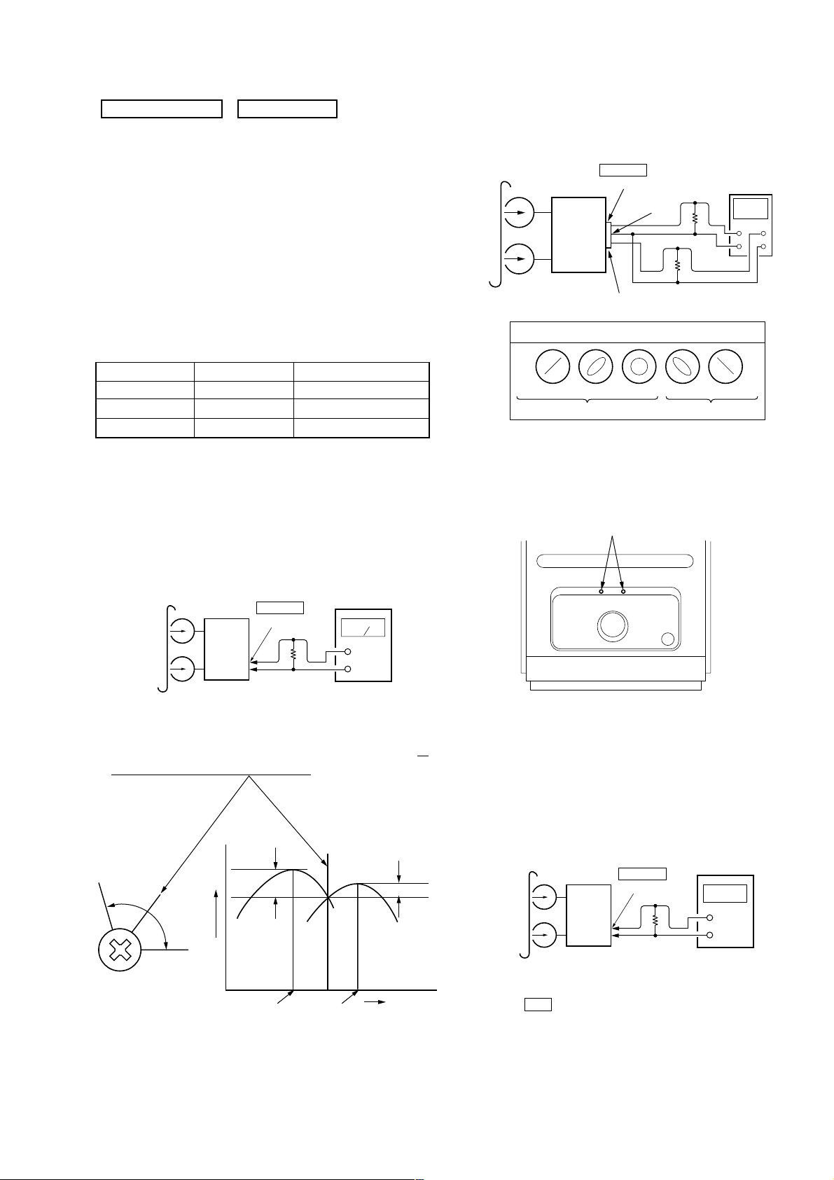
Record/Playback Head Azimuth Adjustment
Procedure:
1. Mode : Playback
test tape
P-4-A100
(10kHz, –10dB)
Signal Used for
10 kHz, –10 dB
3 kHz, 0 dB
315 Hz, 0 dB
J301
PHONES
Output Terminal
Azimuth Adjustment
Tape Speed Adjustment
Level Adjustment
level meter
3. Mode: Playback
4. After the adjustments, apply suitable locking compound to the
parts adjusted.
Adjustment Location:
Adjustment point
set
32
Ω
+
–
2. Turn the adjustment screw and check output peaks. If the peaks
do not match for L-CH and R-CH, turn the adjustment screw
so
that outputs match within 1 dB of peak.
L-CH
peak
screw
position
R-CH
peak
output
level
within
1 dB
L-CH
peak
R-CH
peak
within 1dB
screw
position
(Top view)
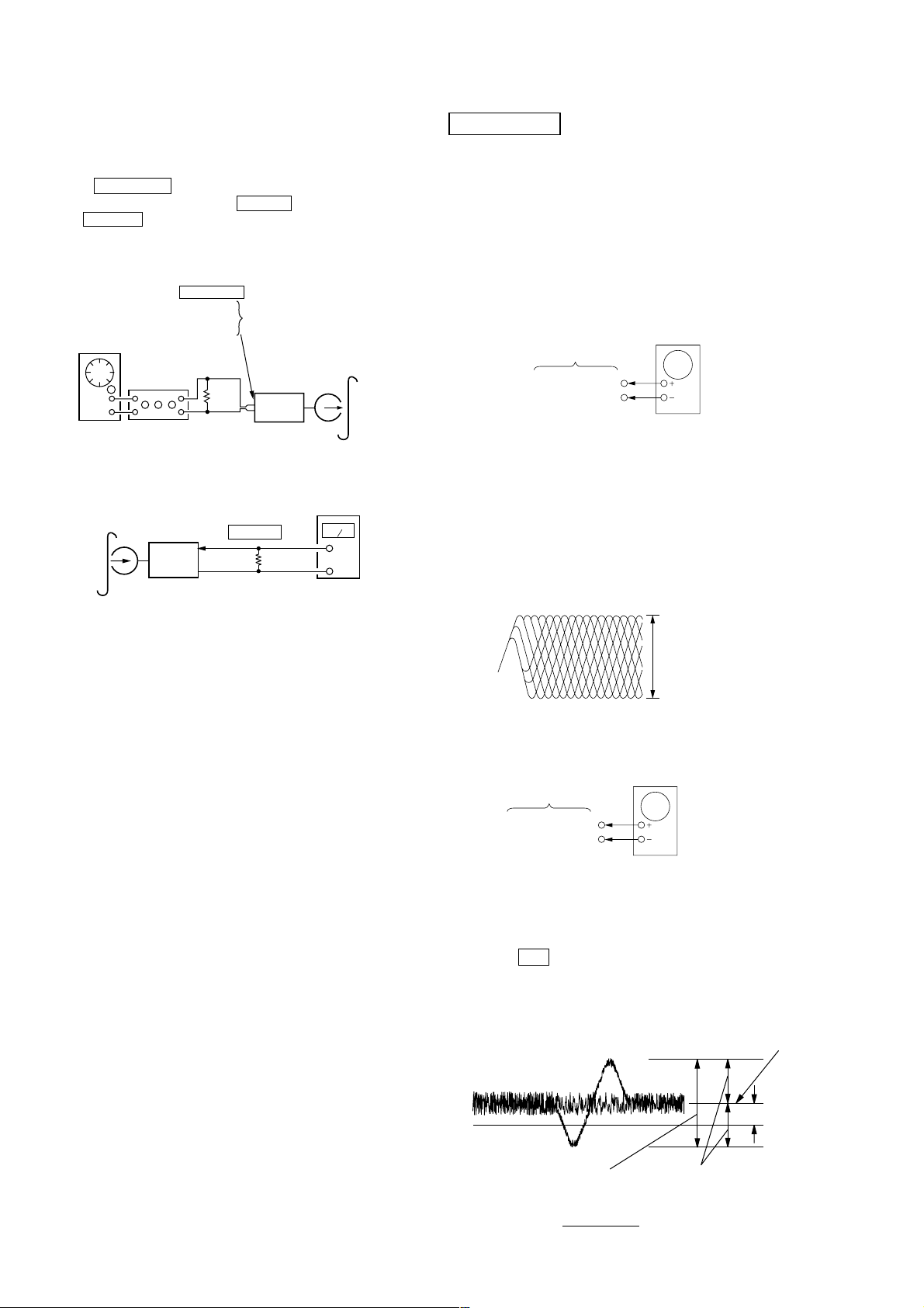
Tape Speed Check
Procedure:
1. MODE : Playback.
test tape
WS-48B
(3kHz, 0dB)
J301
PHONES
Output Terminal
set
32
frequency
counter
Ω
2. Insert the WS-48B into deck.
3. Press the Y button of deck.
4. Check the reading of frequency counter becomes 3000 ± 90 Hz.
Sample Value of Wow and flutter
W.RMS (JIS) less than 0.3%
(test tape: WS-48B)
27
HCD-M10
CD BOARD
Oscilloscope
TP(TE)
TP(DVC 1.65V)
)
e
Record Level Check
Procedure:
1. Press FUNCTION button to select ANALOG IN.
2. Insert a tape into deck, press the z TAPE button, and then press
the X TAPE button to start recording.
3. Mode: Record
PJ301
ANALOG IN
AF OSC
1) 315 Hz
2) 60 Hz
3) 5 kHz
4) 10 kHz
600
attenuator
109 mV (–17 dB)
Ω
blank tap
CS-123
set
4. Mode: Playback
recorded
position
set
J301
PHONES
32
Ω
level meter
CD SECTION
Note :
1. CD Block is basically designed to operate without adjustment.
Therefore, check each item in order given.
2. Use YEDS-18 disc (3-702-101-01) unless otherwise indicated.
3. Use an oscilloscope with more than 10MΩ impedance.
4. Clean the object lens by an applicator with neutral detergent
when the signal level is low than specified value with the
following checks.
RF Level Check
oscilloscope
CD BOARD
TP(RFAC)
TP(DVC 1.65V)
Procedure :
1. Connect oscilloscope to TP (RFAC).
2. Turn the power on.
3. Load a disc (YEDS-18) and playback.
4. Confirm that oscilloscope waveform is clear and check RF signal
level is correct or not.
Note: Clear RF signal waveform means that the shape “◊” can be
clearly distinguished at the center of the waveform.
VOLT/DIV : 200mV
TIME/DIV : 500ns
5. The playback output level should be –2 ±4 dBs (60 Hz),
–1 ±4 dBs (8 kHz) and –3 ±4 dBs (10 kHz) compared with 315Hz
playback level.
level : 1.1 ± 0.3Vp-p
E-F Balance (1 Track jump) Check
Procedure:
1. Connect oscilloscope to TP (TE) and TP (DVC 1.65V).
2. Turn the power on.
3. Load a disc (YEDS-18) and playback the number five track.
4. Press the u button. (Becomes the 1track jump mode.)
5. Confirm that the level B and A (DC voltage) on the oscilloscope
waveform.
Center of
waveform
B
28
0V
B=1.3 ±0.6Vp-p
Specification level: x 100=less than ±22%
A
1.3±0.6Vp-p
Symmetry
A (DC voltage
 Loading...