


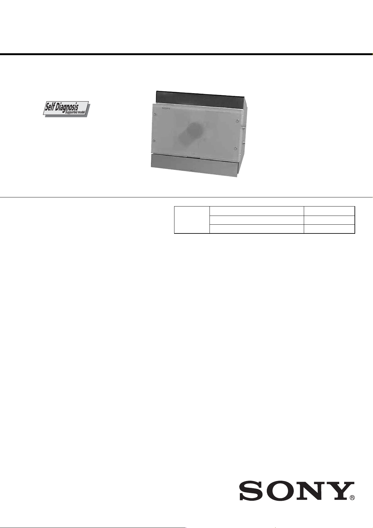
HCD-L7HD
Amplifier section
For the U.S. model
AUDIO POWER SPECIFICATIONS
POWER OUTPUT AND TOTAL
HARMONIC DISTORTION:
With 4-ohm loads, both channels driven, from
120 - 10,000 Hz; rated 25 watts per channel
minimum RMS power, with no more than 10%
total harmonic distortion from 250 milliwatts to
rated output.
North American model:
Continuous RMS power output (reference):
25 + 25 W
(4 ohms at 1 kHz, 10%
THD)
European model:
DIN power output (rated): 20 + 20 W
(4 ohms at 1 kHz, DIN)
Continuous RMS power output (reference):
25 + 25 W
(4 ohms at 1 kHz, 10%
THD)
Music power output (reference):
25 + 25 W
Other models:
The following measured at 220 V AC, 60 Hz
DIN power output (rated): 20 + 20 W
(4 ohms at 1 kHz, DIN,
110 V - 240 V AC)
Continuous RMS power output (reference):
25 + 25 W
(4 ohms at 1 kHz, 10%
THD, 110 V - 240 V AC)
Inputs
MD/TAPE IN (stereo minijack):
Sensitivity 450 mV (MD)/
250 mV (Tape),
impedance 47 kilohms
DIGITAL OPTICAL IN (Supported sampling
frequencies: 32 kHz, 44.1 kHz and 48 kHz)
Outputs
MD/TAPE OUT (stereo minijack):
Sensitivity 250 mV,
impedance 1 kilohmes
PHONES (stereo minijack):
Accepts headphones with
an impedance of 8 ohms
or more
DIGITAL CD OPTICAL OUT (Supported sampling
frequency: 44.1 kHz)
CD player section
System Compact disc and digital
audio system
Laser Semiconductor laser
(λ = 795 nm)
Emission
duration: continuous
Frequency response 2 Hz – 20 kHz
HD recorder section
Capacity 20 GB
Recording system ATRAC 3
Transfer rate 132 kbps
Maximum recording time About 300 h
Maximum number of albums
Library area: 250
Flexible area: 250
Maximum number of tracks
20,000
Maximum number of tracks per album
400
Maximum CD-HD ripping speed
Max. ×2
Tuner section
FM stereo, FM/AM superheterodyne tuner
FM tuner section
Tuning range
North American model: 87.5 - 108.0 MHz
(100-kHz step)
Other models: 87.5 - 108.0 MHz
(50-kHz step)
Antenna FM wire antenna
Antenna terminals 75 ohm unbalanced
Intermediate frequency 10.7 MHz
AM tuner section
Tuning range
North American model: 530 - 1,710 kHz
(with the tuning interval
set at 10 kHz)
531 - 1,710 kHz
(with the tuning interval
set at 9 kHz)
European model: 531 - 1,602 kHz
(with the tuning interval
set at 9 kHz)
Other models: 530 - 1,710 kHz
(with the tuning interval
set at 10 kHz)
531 - 1,602 kHz
(with the tuning interval
set at 9 kHz)
Antenna AM loop antenna, external
antenna terminal
Intermediate frequency 450 kHz
SERVICE MANUAL
Ver 1.2 2003. 12
This set is the tuner, CD, HD and amplifier
section in CMT-L7HD.
CD
SECTION
SPECIFICATIONS
US Model
Canadian Model
AEP Model
UK Model
Model Name Using Similar Mechanism NEW
CD Mechanism Type CDM71B
Base Unit Type BU-31BD63
9-874-073-03
2003L16-1
© 2003.12
Sony Corporation
Home Audio Company
Published by Sony Engineering Corporation
MICRO Hi-Fi COMPONENT SYSTEM
— Continued on next page —

HCD-L7HD
General
Power requirements
North American model: 120 V AC, 60 Hz
European model: 230 V AC, 50/60 Hz
Other models: 110 - 240 V AC ,
Power consumption
European model: See the nameplate
Other models: See the nameplate
Dimensions (w/h/d) Approx. 293 × 246 ×
Mass Approx. 4.3 kg
Design and specifications are subject to change
without notice.
50/60 Hz
0.2 W (at the Power
Saving Mode)
131 mm incl. projecting
parts and controls
Self-diagnosis display
Messages
One of the following messages may appear or
flash in the display during operations.
CD
Complete!
CD editing (Disc Memo) finished normally.
File Full
There are already 100 disc titles stored in the
system.
Initialize
The system is being initialized. You cannot load a
CD during this time. Wait until “Initialize”
disappears from the display.
No Disc
There is no disc in the CD player.
—OVER—
You have reached the end of the CD while
pressing and holding down M during playing
pause.
Push STOP!
You pressed PLAY MODE on the remote during
playback.
You pressed STORAGE MODE during playback.
You pressed STORAGE MODE during manual
recording of a CD.
Step Full!
You tried to program 26 tracks (steps) or more.
HD
Already Done
You tried to perform High-Speed Synchro Storage
for a CD that has already been completely
recorded.
Auto Cut
The system is pausing the recording because
silence continued for 30 seconds or more during
digital recording.
Blank Disc
There is no track on the HD.
2

HCD-L7HD
Cannot Copy
You tried to play a CD with a format that the
system does not support, such as a CD-ROM. The
sound source is a copy of commercially available
music software.
Cannot Edit
You tried to edit in Shuffle Play, or you tried to
register a track to a playlist that already contains
400 tracks.
Cannot Play
The system cannot play the track because of
damage to the audio data.
Cannot Rec
You tried to record to the HD with HD selected as
the sound source.
You tried to perform manual recording from the
CD with “AUTO” selected as the storage mode.
You pressed REC with “AUTO” selected as the
storage mode.
You tried to record a CD to the HD without
loading the CD.
Cannot STORAGE
You tried to record to the HD with less than 131
recordable tracks remaining on the HD.
You tried to record to the HD with less than 240
minutes of recordable time remaining on the HD.
You tried to perform High-Speed Synchro Storage
with no blank album in the Library area.
Check OPT-IN
A moment’s lighting is due to the signals of the
digital program being recorded. This does not
affect the recorded material.
While recording from a digital component
connected through the DIGITAL OPTICAL IN
jack, the digital connecting cable was unplugged or
the digital component turned off.
Complete!
The editing operation of the HD is completed.
The system is copying a title or artist name.
Copying
The system is copying the text data.
Drive Error
Consult your Sony dealer or local authorized Sony
service facility.
Drive Full!
Recording tracks is not possible because there is
not enough recordable space on the HD or the
maximum number of recordable tracks has been
reached.
Erasing
The system is erasing data from the HD. Do not
disconnect the power cord.
Format Error
Consult your Sony dealer or local authorized Sony
service facility.
Impossible
You tried to make an impossible editing or
recording operation.
Library Making
The system is recording data to the HD.
Name Full!
The naming capacity of the HD has reached its
limit (about 127 characters).
No Name
The album or track has not been labelled.
No Signal
The system has detected a silent portion during
recording.
Not Found
No matches were found for Keyword Search.
Please Wait
You tried to perform High-Speed Synchro Storage
while the system was collating data between the
CD and the HD.
You tried to perform High-Speed Synchro Storage
while the system was preparing for Auto Storage
and High-Speed Synchro Storage.
Push STOP!
You pressed PLAY MODE on the remote during
playback.
You pressed SEARCH on the remote during
playback.
Rec Error
Proper recording is not possible.
– Rehearsal –
The HD is playing the specified dividing point for
confirmation during the Divide function.
The HD is playing the specified Highlight position
for confirmation during the Highlight Play
function.
REMOTE
The system is being connected to your computer.*
Retry
The system is retrying reading data from the CD
during High-Speed Synchro Storage.
Smart Space
The signal was input again after silence continued
for 3 or more but less than 30 seconds during
digital recording.
STORAGE NOW
You tried to turn off the system while the system
was storing data to the HD.
TOC Reading
The system is reading data from the HD.
Track End
You have reached the end of the track while
adjusting the dividing point during the Divide
function.
Track Full!
Recording tracks is not possible because there are
400 tracks in the album. Select another album for
recording.
Timer
OFF TIME NG!
The stopping time is the same as the starting time
in the Daily Timer operation.
OVERLAP!
The Daily Timer or timer-recording setting that
you attempted to make partially or wholly
coincides with another setting.
* If “REMOTE” appears under other circumstances,
turn off the system, then turn on it again.
3

HCD-L7HD
TABLE OF CONTENTS
1. SERVICING NOTES
2. GENERAL ·········································································· 8
3. DISASSEMBLY ······························································ 10
3-1. Bottom Plate,Case ·······················································11
3-2. Front Panel Section ····················································· 11
3-3. POWER Board, AM/FM Tuner ··································· 12
3-4. HDD Board, HDD SUB Board ··································· 12
3-5. MAIN Board ······························································· 13
3-6. Cover (HDD-Top), Cover (HDD-Bottom) ·················· 13
3-7. AMP Board, REG Board ············································· 14
3-8. Switching Regulator ···················································· 14
3-9. Indicator (BS), LED Board (R) ···································15
3-10.LED Board (L) ···························································· 15
3-11.FL Board ·····································································16
3-12.TOUCH SW Board, SWITCH Board ························· 16
3-13.CD Board·····································································17
3-14.BD Board·····································································17
3-15.Base Unit (BU-31BD63) ············································· 18
3-16.BU-31 Assy, Sled Motor Assy (M102) ······················· 18
3-17.CD Mechanism (CDM71B) ········································ 19
3-18.L.MOTOR Board ························································· 19
3-19.C.MOTOR Board, L.SENSOR Board ························· 20
3-20.ENCODER Board, D.SENSOR Board ······················· 21
3-21.Pulley (RTR) Assy, Pulley (RTL) Assy,
Belt (CDM71), Belt (Roller) (L) ································· 22
3-22.Pulley (SPT) Assy, Gear (RT) Assy, Gear(KT),
Belt (CDM71) ····························································· 24
4. TEST MODE ···································································· 26
······················································· 5
6. DIAGRAMS······································································31
6-1. Block Diagrams ··························································· 31
6-2. Circuit Boards Location ·············································· 34
6-3. Printed Wiring Board – BD Section (Side A) – ··········· 35
6-4. Printed Wiring Board – BD Section (Side B) –···········36
6-5. Schematic Diagram – BD Section – ···························· 37
6-6. Printed Wiring Board – MOTOR Section – ················38
6-7. Schematic Diagram – MOTOR Section – ··················· 39
6-8. Printed Wiring Board – HDD1 Section (Side A) – ····· 40
6-9. Printed Wiring Board – HDD1 Section (Side B) – ·····41
6-10.Schematic Diagram – HDD1 Section (1/2) –·············· 42
6-11.Schematic Diagram – HDD1 Section (2/2) –·············· 43
6-12.Printed Wiring Board – HDD2 Section –···················· 44
6-13.Schematic Diagram – HDD2 Section (1/2) –·············· 45
6-14.Schematic Diagram – HDD2 Section (2/2) –·············· 46
6-15.Printed Wiring Board – MAIN Section (Side A) – ····· 47
6-16.Printed Wiring Board – MAIN Section (Side B) – ·····48
6-17.Schematic Diagram – MAIN Section (1/2) –·············· 49
6-18.Schematic Diagram – MAIN Section (2/2) –·············· 50
6-19.Printed Wiring Board – CD Section – ························· 51
6-20.Schematic Diagram – CD Section –····························52
6-21.Printed Wiring Board – AMP Section (Side A) –········ 53
6-22.Printed Wiring Board – AMP Section (Side B) – ········ 54
6-23.Schematic Diagram – AMP Section – ························· 55
6-24.Printed Wiring Board – DISPLAY Section – ·············· 56
6-25.Schematic Diagram – DISPLAY Section – ················· 57
6-26.Printed Wiring Board – CONTROL Section – ············ 58
6-27.Schematic Diagram – CONTROL Section –···············59
6-28.Printed Wiring Board – POWER Section –·················60
6-29.Schematic Diagram – POWER Section – ··················· 61
6-30.IC Pin Function Descriptions ······································ 63
5. ELECTRICAL ADJUSTMENTS ·······························30
7. EXPLODED VIEWS ······················································ 72
7-1. Case Section ································································72
7-2. Chassis Section ···························································· 73
7-3. Frot Panel Section ······················································· 74
7-4. Mechanism Section(CDM71B)-1································ 75
7-5. Mechanism Section(CDM71B)-2································ 76
7-6. Base Unit (BU-31BD63) ············································· 77
8. ELECTRICAL PARTS LIST ······································· 78
4
SECTION 1
SERVICING NOTES
HCD-L7HD
NOTES ON HANDLING THE OPTICAL PICK-UP
BLOCK OR BASE UNIT
The laser diode in the optical pick-up block may suffer electrostatic
break-down because of the potential difference generated by the
charged electrostatic load, etc. on clothing and the human body.
During repair, pay attention to electrostatic break-down and also
use the procedure in the printed matter which is included in the
repair parts.
The flexible board is easily damaged and should be handled with
care.
NOTES ON LASER DIODE EMISSION CHECK
The laser beam on this model is concentrated so as to be focused on
the disc reflective surface by the objective lens in the optical pickup block. Therefore, when checking the laser diode emission,
observe from more than 30 cm away from the objective lens.
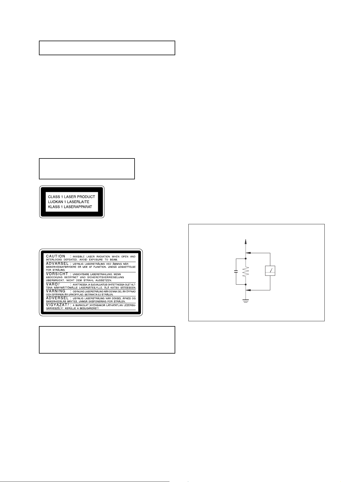
Laser component in this product is capable
of emitting radiation exceeding the limit for
Class 1.
This appliance is classified as a CLASS 1 LASER product. The
CLASS 1 LASER PRODUCT MARKING is located on the rear
exterior.
SAFETY CHECK-OUT
After correcting the original service problem, perform the
following safety checks before releasing the set to the customer:
Check the antenna terminals, metal trim, “metallized” knobs, screws,
and all other exposed metal parts for A C leakage. Check leakage as
described below.
LEAKAGE
The A C leakage from any exposed metal par t to earth ground and
from all exposed metal parts to any exposed metal part having a
return to chassis, must not exceed 0.5 mA (500 microamperes).
Leakage current can be measured by any one of three methods.
1. A commercial leakage tester, such as the Simpson 229 or RCA
WT -540A. Follo w the manufacturers’ instructions to use these
instruments.
2. A battery-operated AC milliammeter. The Data Precision 245
digital multimeter is suitable for this job.
3. Measuring the voltage drop across a resistor by means of a
VOM or battery-operated AC voltmeter . The “limit” indication
is 0.75 V, so analog meters must have an accurate lo w-v oltage
scale. The Simpson 250 and Sanwa SH-63Trd are e xamples of
a passive VOM that is suitable. Nearly all battery operated
digital multimeters that have a 2V AC range are suitable. (See
Fig. A)
To Exposed Metal
Parts on Set
This caution
label is
located inside
the unit.
CAUTION
Use of controls or adjustments or performance of procedures
other than those specified herein may result in hazardous radiation
exposure.
SAFETY-RELATED COMPONENT WARNING!!
COMPONENTS IDENTIFIED BY MARK 0 OR DOTTED LINE WITH
MARK 0 ON THE SCHEMATIC DIAGRAMS AND IN THE PARTS
LIST ARE CRITICAL TO SAFE OPERATION. REPLACE THESE
COMPONENTS WITH SONY PARTS WHOSE PART NUMBERS
APPEAR AS SHOWN IN THIS MANUAL OR IN SUPPLEMENTS
PUBLISHED BY SONY .
AC
0.15 µF
Fig. A. Using an A C v oltmeter to check A C leakage.
1.5 kΩ
Earth Ground
Voltmeter
(0.75 V)
Notes on chip component replacement
•Never reuse a disconnected chip component.
• Notice that the minus side of a tantalum capacitor may be
damaged by heat.
Flexible Circuit Board Repairing
•Keep the temperature of soldering iron around 270˚C
during repairing.
• Do not touch the soldering iron on the same conductor of the
circuit board (within 3 times).
• Be careful not to apply force on the conductor when soldering
or unsoldering.
ATTENTION AU COMPOSANT AYANT RAPPORT
LES COMPOSANTS IDENTIFÉS P AR UNE MARQUE 0 SUR LES
DIAGRAMMES SCHÉMA TIQUES ET LA LISTE DES PIÈCES SONT
CRITIQUES POUR LA SÉCURITÉ DE FONCTIONNEMENT. NE
REMPLACER CES COMPOSANTS QUE PAR DES PIÈSES SONY
DONT LES NUMÉROS SONT DONNÉS DANS CE MANUEL OU
DANS LES SUPPÉMENTS PUBLIÉS PAR SONY.
À LA SÉCURITÉ!
5

HCD-L7HD
NOTES ON HARD DISC
The hard disc has a high storage density and reads or writes data in
a short time with compared to the floppy disk. On the other hand, it
may be easily damaged by mechanical vibration, shock or dust.
Keep the hard disc away from magnets.
Although the hard disc has safety devices to prevent losing data due
to mechanical vibration, shock or dust, you should be careful when
handling the recorder. Avoid damaging your data:
• Do not cause a shock or strong vibration to the recorder.
• Do not place the recorder in a location subject to mechanical
vibration or in unstable location.
• Do not move the recorder while the power is on.
• Do not turn off the recorder while the HDD indicator lights up
blue.
• Do not use the recorder in a place subject to extreme changes in
temperature (temperature gradient less than 18 °F (10 °C)/ hour).
•Keep any magnetic objects, including a TV set, speaker , magnet,
and magnetic bracelet, away from the recorder.
If the hard disc is damaged, data cannot be restored or recovered.
NOTES ON DIGITAL AMPLIFIER
Cause of the Digital Amplif ier, do not connect the speaker ter minals
to the chasis, or connect the terminals of the right speakers with
those of the left speaker. (None of the speaker terminals is the
negative(–) terminal of the speak er. So,do not connect the earth lead
of this unit to the speaker terminals.)
Unleaded solder
Boards requiring use of unleaded solder are printed with the leadfree mark (LF) indicating the solder contains no lead.
(Caution: Some printed circuit boards may not come printed with
the lead free mark due to their particular size.)
: LEAD FREE MARK
Unleaded solder has the following characteristics.
• Unleaded solder melts at a temperature about 40°C higher than
ordinary solder.
Ordinary soldering irons can be used but the iron tip has to be
applied to the solder joint for a slightly longer time.
Soldering irons using a temperature regulator should be set to
about 350°C.
Caution: The printed pattern (copper foil) may peel away if the
heated tip is applied for too long, so be careful!
• Strong viscosity
Unleaded solder is more viscous (sticky , less prone to flo w) than
ordinary solder so use caution not to let solder bridges occur such
as on IC pins, etc.
• Usable with ordinary solder
It is best to use only unleaded solder but unleaded solder may
also be added to ordinary solder.
6
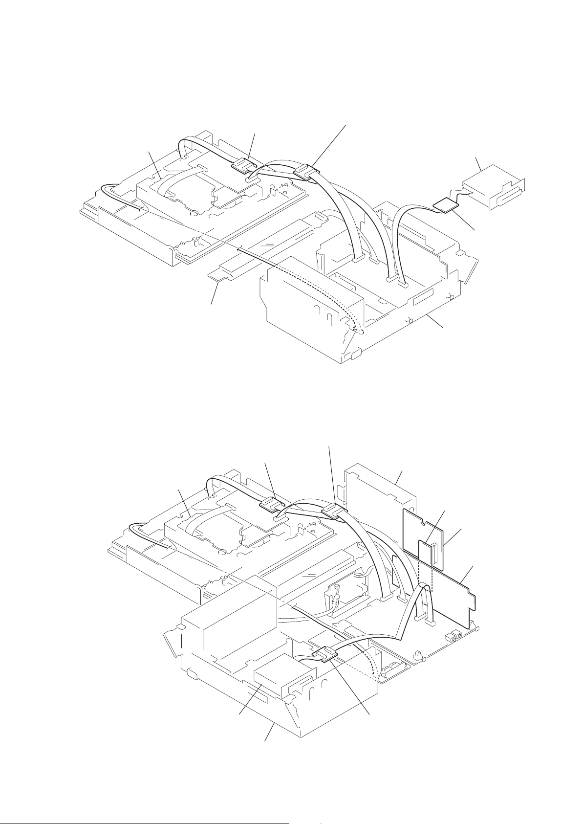
• Service Position -1
)
d
HCD-L7HD
BD board
FL board
JIG
(J-2501-077-A)(13P)
JIG
(J-2501-167-A)(17P)
FM/AM tuner
JIG
(J-2501-076-A)(11P
chassis
• Service Position -2
(Checking For Hard Disc Section)
BD board
JIG
(J-2501-077-A)(13P)
JIG
(J-2501-167-A)(17P)
hard disk
JIG
(J-2501-202-A)(11P)
HDD SUB boar
HDD IF board
FM/AM tuner
JIG
(J-2501-076-A)(11P)
chassis
7
HCD-L7HD
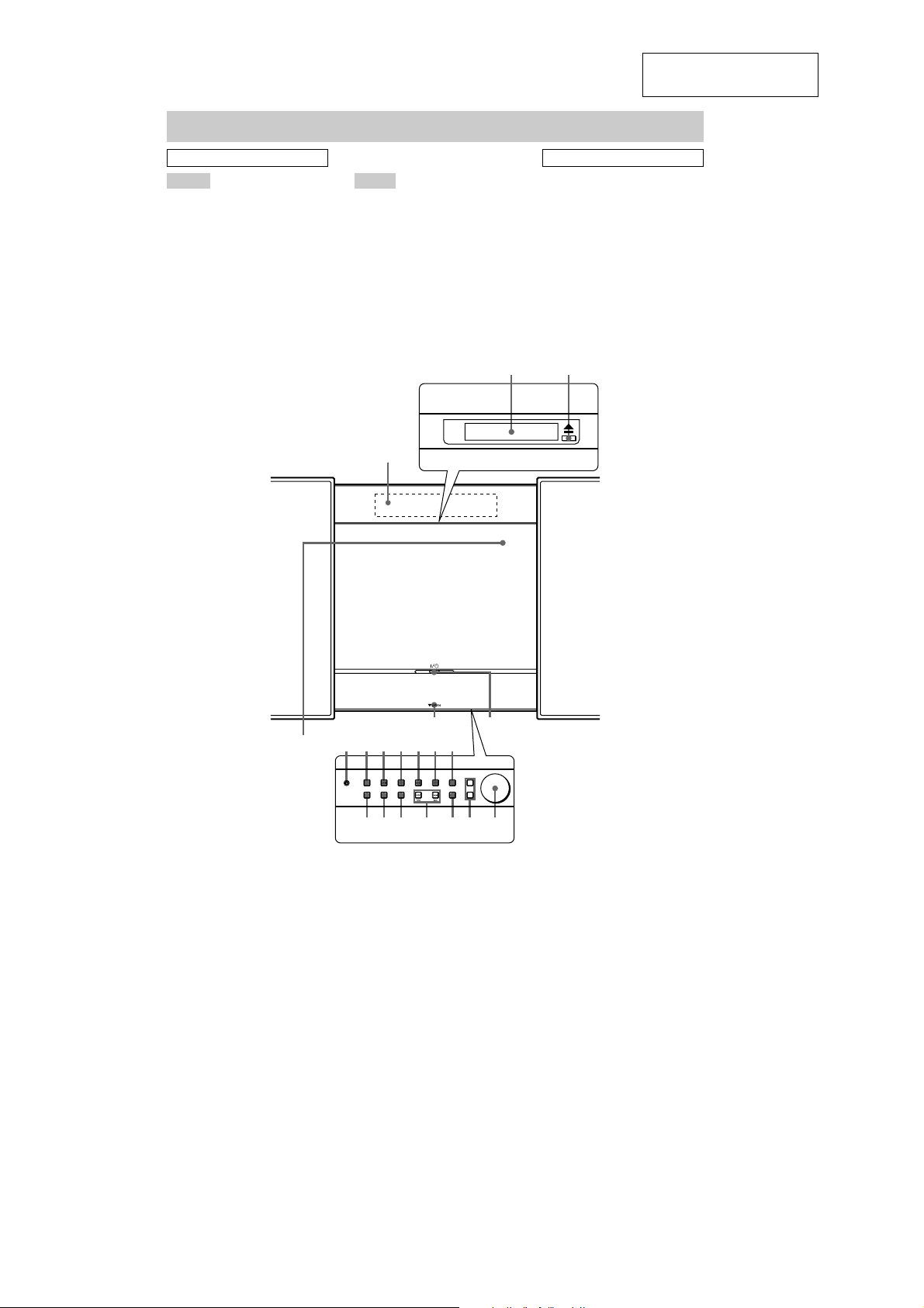
Main unit
SECTION 2
GENERAL
This section is extracted
from instruction manual.
ALPHABETICAL ORDER
A – H
ALBUM dial qf (18, 19, 21, 26)
CD cover 2 (14, 15)
CD u qa (14 - 16, 25)
CD x qs (15, 16, 24, 25)
DISPLAY 8 (39, 44, 45)
Display window 1 (44, 45)
FUNCTION qh (14 - 22, 25 - 28,
30, 32 - 35, 57)
HD u 9 (18, 20 - 22, 25, 26)
HD x q; (18, 25, 26, 30)
HIGH SPEED SYNC ql (25)
P – Z
PHONES jack 7
REC w; (26, 28)
Remote sensor 6
STORAGE MODE qk (14, 25,
26)
TUNER/BAND qd (37, 38)
TUNING +/– qj (37, 38)
VOL +/– qg (41)
1
BUTTON DESCRIPTIONS
@/1 (power) 4 (11, 41, 42)
./> qj (15, 16, 18)
m/M qj (15, 18)
Z 3 (14, 15)
V OPEN 5
To open the front cover, push
down on V OPEN.
2
3
6
789q;
qlqk
54
qaqsqd
qgqhqjw;
qf
8
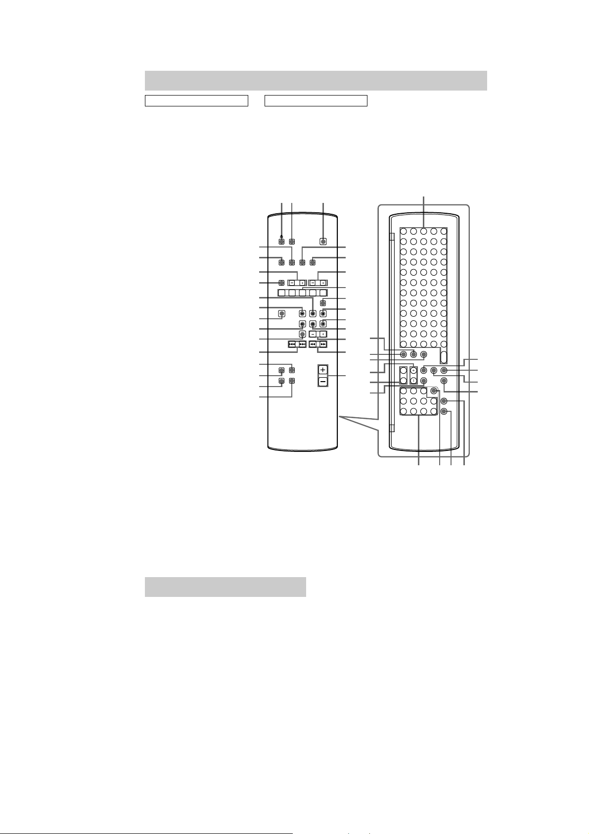
Remote control
HCD-L7HD
ALPHABETICAL ORDER
ALBUM eh (19)
ALBUM FAVORITES 7 (22)
ALBUM MEMORY 8 (22)
ALBUM +/– 6 (18, 19, 21, 26)
CAPS rd (16, 31)
CD N wa (14 - 16, 25)
CD X qa (15)
CD x q; (15, 16, 24, 25)
CLEAR es (15 - 17, 29, 31, 39)
CLOCK/TIMER SELECT eg
(41 - 43)
CLOCK/TIMER SET ef (13, 41,
42)
CURSOR T/t el (13, 17, 20,
21, 31, 35, 42)
DIMMER 5 (44)
DISPLAY wk (39, 44, 45)
DSG qk (40)
ENTER/YES e; (13, 15 - 17,
19 - 21, 27 - 37, 39, 41 - 43, 57)
FM MODE qg (38)
FUNCTION ws (14 - 22, 25 - 28,
30, 32 - 35, 57)
HD N wd (18, 20 - 22, 25, 26)
HD X wf (18, 25, 26)
HD x 9 (18, 25, 26, 30)
HIGHLIGHT wg (21)
HISTORY +/– wh (22)
MENU/NO ek (17, 20, 27 - 39,
57)
MENU +/– r; (13, 17, 20, 21,
27 - 36, 41 - 43)
NAME rs (16, 39)
Numeric buttons for selecting an
album or track ej (15, 19, 38)
PLAYLIST ed (19, 20)
PLAY MODE qh (14 - 18, 21)
PRESET EQ qj (40)
REPEAT qg (15, 18)
SCROLL 4 (17, 45)
SEARCH ea (20)
SLEEP 2 (40)
SML ra (16, 31)
Text input buttons wl (16, 31)
TIME wj (16, 44, 45)
TUNER BAND w; (37, 38)
TUNING MODE qh (37, 38)
TUNING +/– qs (37, 38)
VOL +/– qf (41)
BUTTON DESCRIPTIONS
@/1 (power) 3 (11, 41, 42)
./> ql (15, 16, 18)
m/M qd (15, 18)
Z 1 (14, 15)
12 3
wk
wj
wh
wg
wf
wd
ws
wa
w;
ql
qk
qj
qh
qg
4
5
6
7
8
9
q;
qa
qs
qd
qf
rd
rs
ra
r;
el
ek
wl
e;
ea
es
ed
ej ehegef
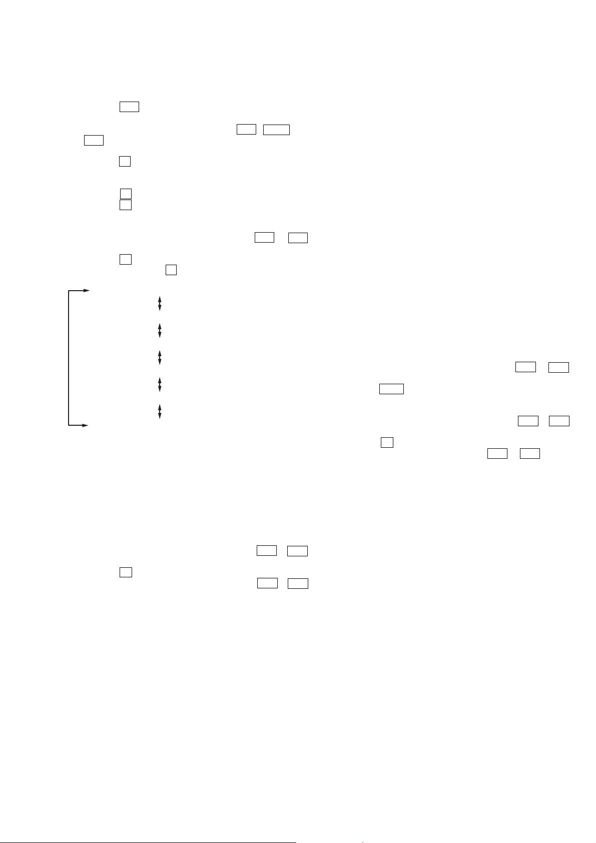
Setting the clock
1 Turn on the system.
2 Press CLOCK/TIMER SET on the
remote.
3 Press MENU + or – on the remote
repeatedly to set the day, and then
press ENTER/YES or CURSORt on
the remote.
The hour indication flashes.
4 Press MENU + or – on the remote
repeatedly to set the hour, and then
press ENTER/YES or CURSORt on
the remote.
The minute indication flashes.
5 Press MENU + or – on the remote
repeatedly to set the minute, and then
press ENTER/YES on the remote.
If you make a mistake
Press TCURSOR or CURSORt on the
remote repeatedly until the indication you want
to change (day, hour, minute) flashes, and then
change the setting.
To adjust the clock
1
Press CLOCK/TIMER SET on the remote.
2
Press MENU + or – on the remote repeatedly
until “CLOCK SET?” appears in the display,
and then press ENTER/YES on the remote.
3
Do the same procedures as steps 3 to 5
above.
9
HCD-L7HD
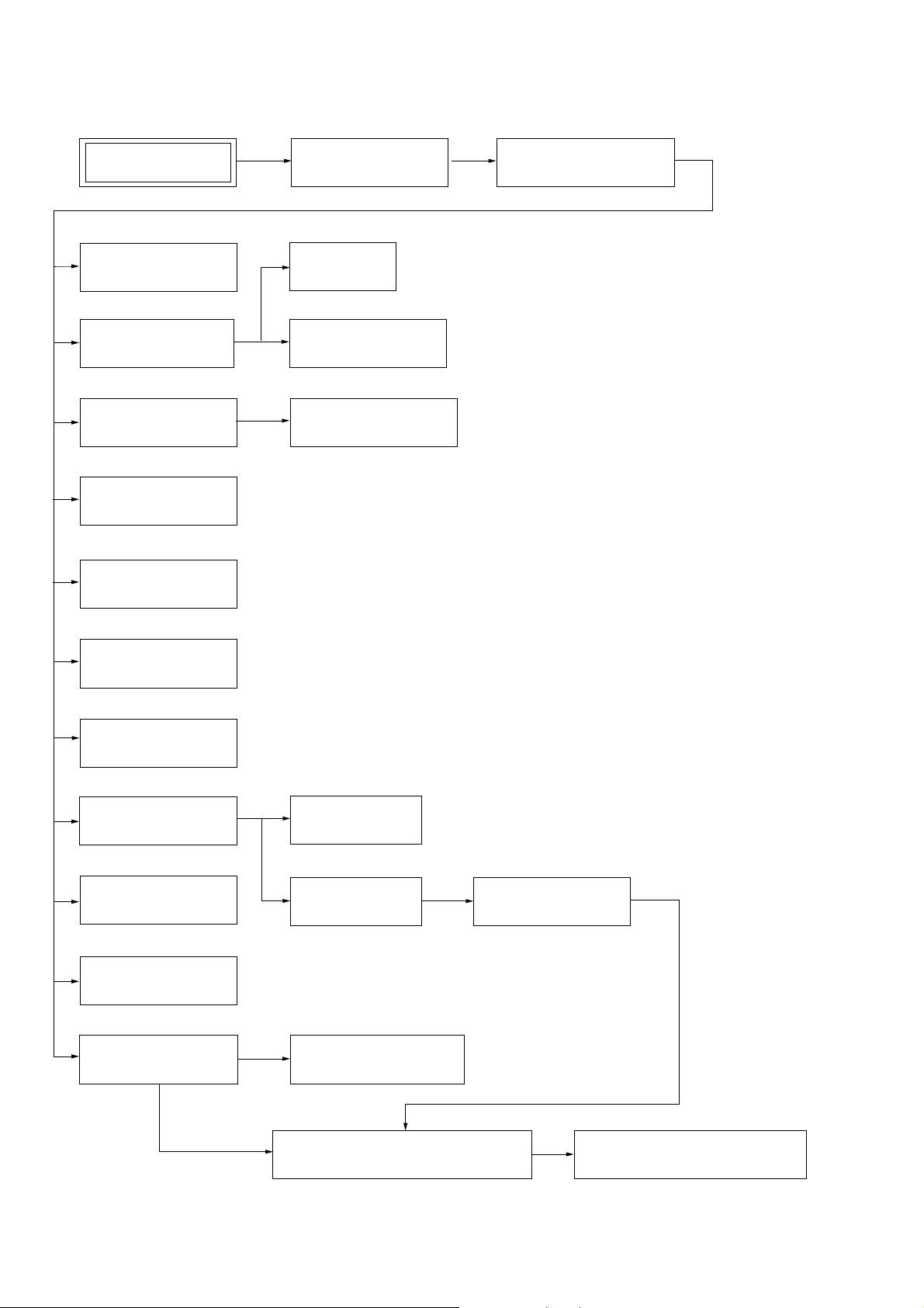
SECTION 3
DISASSEMBLY
Note : This set can be disassembled in the order shown below.
SET (HCD-L7HD)
POWER BOARD,
AM/FM TUNER
HDD BOARD,
HDD SUB BOARD
AMP BOARD,
REG BOARD
INDICATOR (BS),
LED BOARD (R)
LED BOARD (L)
BOTTOM PLATE,CASE
MAIN BOARD
COVER (HDD-TOP),
COVER (HDD-BOTTOM)
SWITCHING REGULATOR
FRONT PANEL SECTION
FL
BOARD
TOUCH SW BOARD,
SWITCH BOARD
CD MECHANISM
(CDM71B)
CD
BOARD
BD
BOARD
BASE UNIT
(BU-31BD63)
C.MOTOR BOARD,
L.SENSOR BOARD
L.MOTOR BOARD
HOLDER ASSY ,
SLED MOTOR ASSY (M102)
ENCODER BOARD,
D.SENSOR BOARD
10
PULLEY (RTR) ASSY,PULLEY (RTL) ASSY,
BELT (CDM71), BELT (ROLLER) (L)
PULLEY (SPT) ASSY,GEAR (RT)ASSY,
GEAR (KT), BELT (CDM71)
Note : Follow the disassembly procedure in the numerical order given.
e
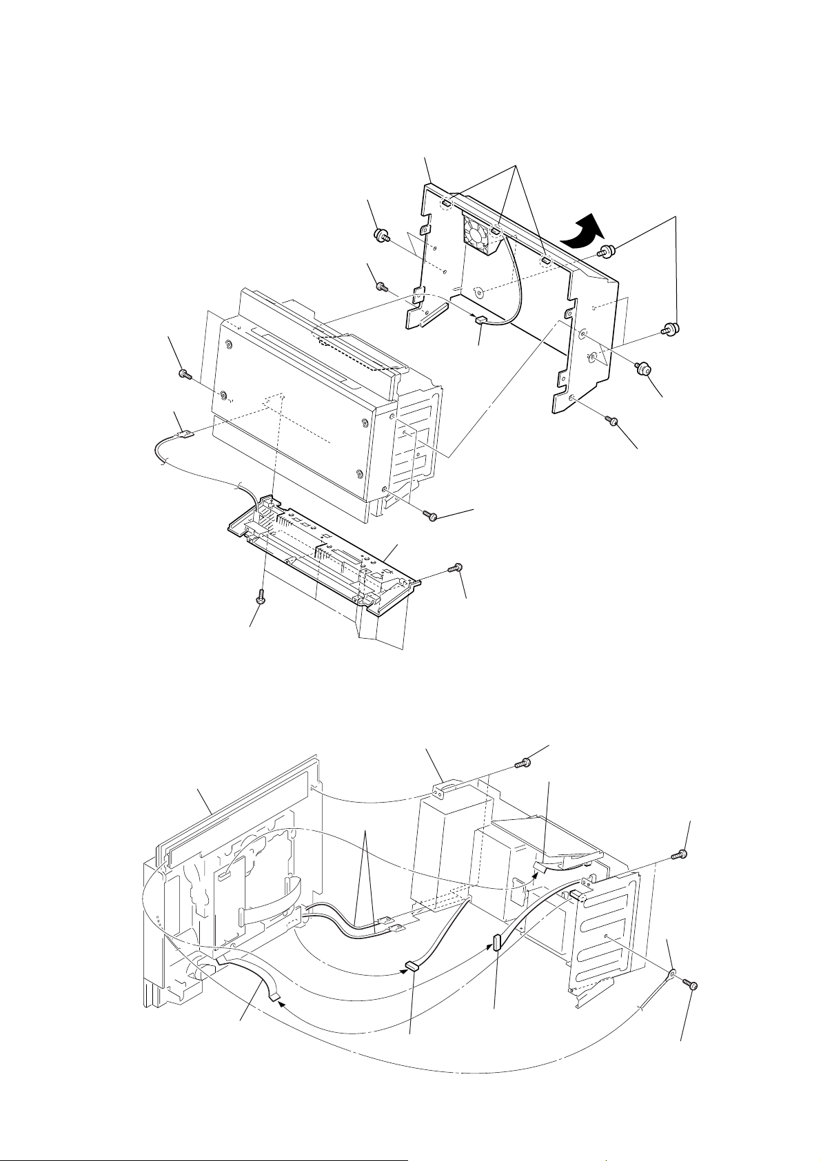
3-1. Bottom Plate,Case
qg
case
6
t
wo screws (SS)
7
s
qa
t
wo screws
(+PTT 3
3
earth plate
× 6
crew (+PTT 3
)
× 6
)
qd
qf
c
onnector
(CN801)
three
claws
qs
5
f
our screws (SS)
8
t
HCD-L7HD
wo screws (SS)
1
six screws (+BVTP 3
3-2. Front Panel Section
qa
front panel section
× 8
9
s
crew (+PTT 3
q;
t
wo screws (+PTT 3
4
b
ottom plate
2
three screws (+BVTP 2.6
)
q;
c
hassis section
7
1
two
earth plates
× 6
)
×
8)
6
two screws (+BVTP 2.6
flat type wire (17 core)
5
two
screws (+BVTP 2.6
×
× 6
)
8)
×
8)
9
f
lat type wire (13 core)
8
c
onnector
(CN1321)
4
c
onnector (CN1201)
2
3
ground wir
screw (+BVTP 3
×
6)
11
HCD-L7HD
)
)
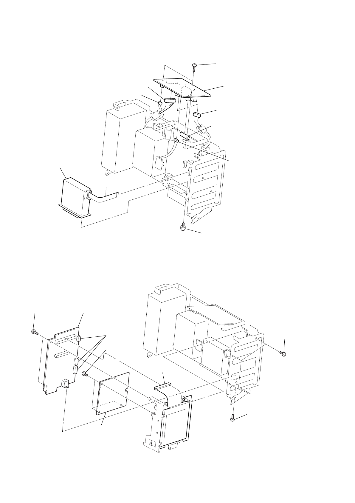
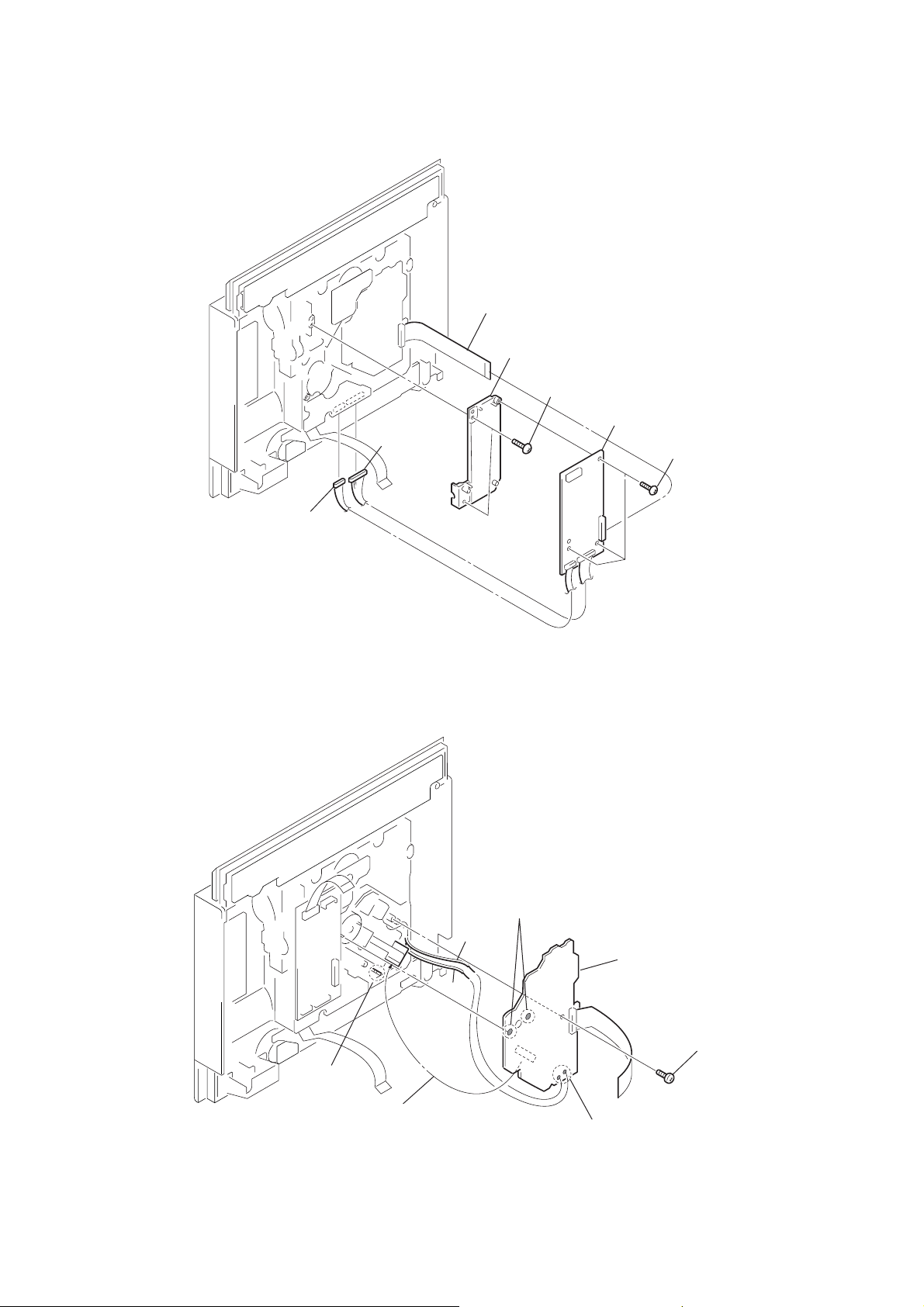
3-3. POWER Board, AM/FM Tuner
3
4
connector (CN851)
q;
AM/FM t
uner
9
flat type wire
(11core or 15core)
connector (CN800)
1
two
screws
(+BVTP 3
7
POWER board
5
connector (CN852)
2
connector (CN500)
6
connector (CN803
×
8)
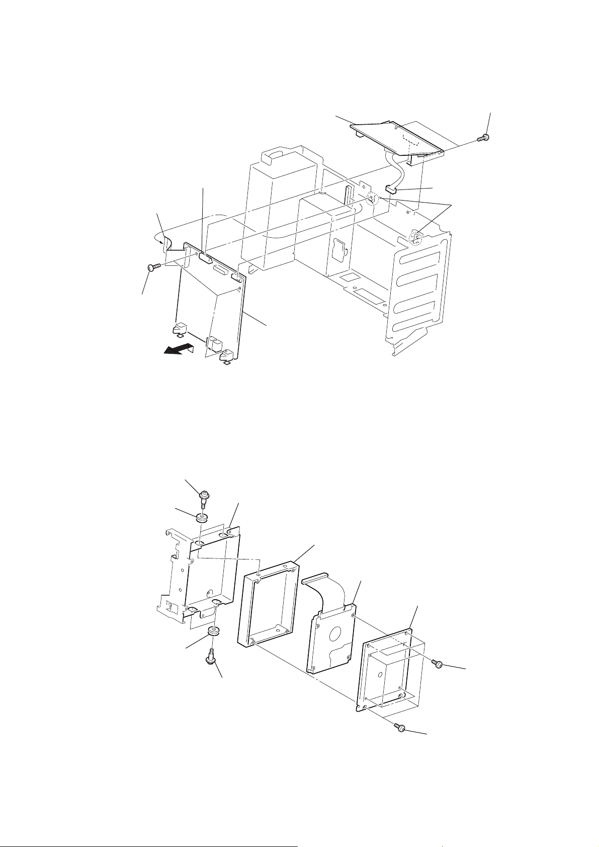
3-4. HDD Board, HDD SUB Board
6
4
two
screws
(+BVTP 3
×
8)
HDD IF board
3
connector
(CN507,508,503)
7
(+BVTT 3
three
screws
×
6)
5
(CN1002)
harness
8
two
screws
(+BVTP 3
×
8)
2
four
screws
(+BVTP 3
×
8
12
8
HDD SUB board
1
screw
(+BVTP 3
×
8)
3-5. MAIN Board
)
)
5
flat type wire (23core)
three
6
(+BVTP 3
screws
3
connector (CN500)
×
8)
4
POWER
board
2
two
screws (+BVTP 3
1
connector (CN504)
8
two
HCD-L7HD
×
claws
8
9
7
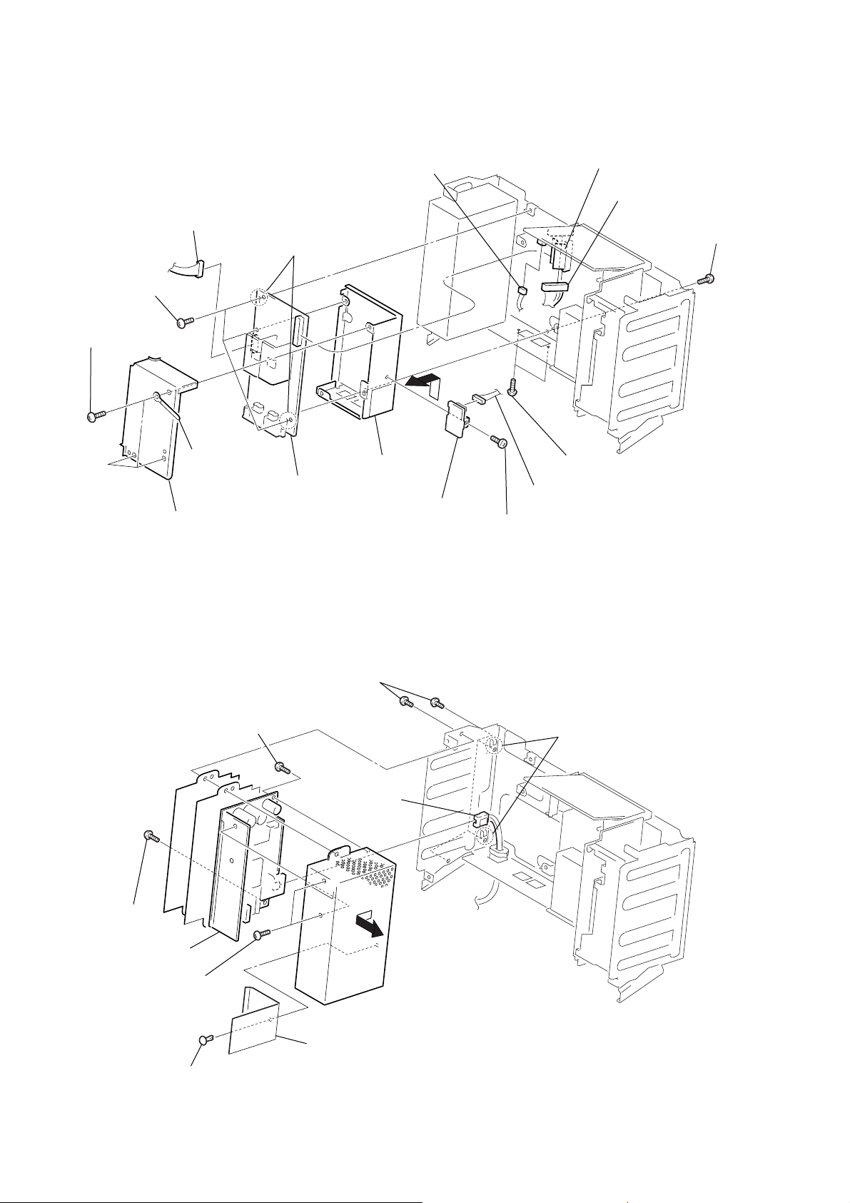
3-6. Cover (HDD-Top), Cover (HDD-Bottom)
1
two
screws
(+BVTPWH M3)
5
shield case (HDD)
2
two insulators
MAIN board
7
cover (HDD-top)
9
HDD
q;
cover (HDD-bottom)
4
two insulators
3
two
screws
(+BVTPWH M3)
6
four
(+BVTP 3
8
four
(+BVTT 3
screws
×
8)
screws
×
6
13
HCD-L7HD
)
3-7. AMP Board, REG Board
9
connector (CN300)
q;
three
screws
× 6
screws
×
)
8)
(+BVTP 3
6
three
(+BVTP 3
qa
two
1
connector (CN851)
hooks
qs
3
flat type wire (23core)
2
connector (CN800)
5
screw
(+BVTP 3
×
8
7
8
shield case (SM-top)
3-8. Switching Regulator
6
(+BVTP 3
ground wire
qg
screw
AMP board
1
(+BVTP 3
×
8)
qf
(SM-bottom)
four
screws
4
shield case
×
6)
connector
qj
REG
board
qd
connector (CN804)
qh
screw
(+BVTP 3
3
4
two
screws
(+BVTP 3
×
8)
two
hooks
×
8)
14
5
screw
(+BVTP 3
q;
switching
7
(+BVTP 3
×
8)
regurator
two
screws
8
×
8)
nylon rivet
2
9
sheet (power box)
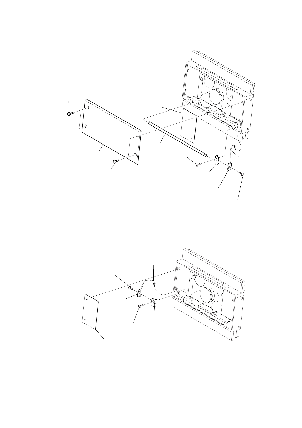
3-9. Indicator (BS), LED Board (R)
r
2
two screws
(panel)
3
ornamental plate (CD)
1
two screws
(panel)
4
sheet (CD2)
8
indicator (BS)
6
s
crew (+BTP 2.6
×
6)
7
holder (LED-R)
HCD-L7HD
5
connecto
(CN1303)
3-10. LED Board (L)
5
screw (+BVTP 2.6
×
8)
6
LED board (L)
1
connector (CN1302)
4
3
screw (+BTP 2.6
holder (LED-L)
×
6)
q;
LED board (R)
9
screw (+BVTP 2.6
×
8)
2
sheet (CD2)
15
HCD-L7HD
)
d
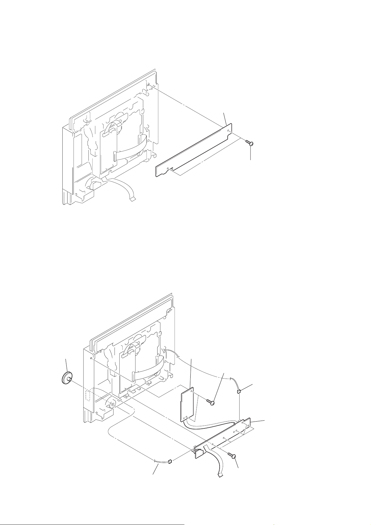
3-11. FL Board
2
FL board
1
two
screws (+BVTP 2.6
×
8
3-12. TOUCH SW Board, SWITCH Board
5
knob jog assy
2
TOUCH SW board
1
two
(+BVTP 2.6
screws
×
8)
3
c
onnector (CN1302)
7
SWITCH boar
16
4
c
onnector (CN1303)
6
f
ive screws
(+BVTP 2.6
×
8)
3-13. CD Board
)
)
4
c
onnector
(CN751)
1
f
lat type wire (19 core)
7
bracket (CD-MT)
6
two screws (+BVTP 3
5
CD board
×
8)
2
three screws
(+BVTP 2.6
HCD-L7HD
×
8
3-14. BD Board
3
c
onnector
(CN752)
1
Remove solder (two portions ).
(BLK)
6
BD board
5
h
ook
4
flxible
(RED)
board
2
Remove solder (two portions ).
3
screw
(+BTP 2.6
×
8
17
HCD-L7HD
)
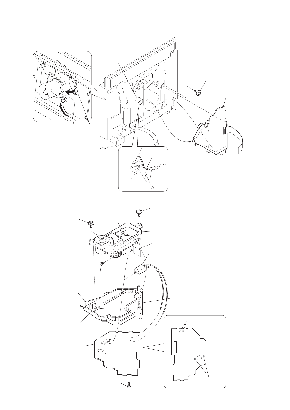
3-15. Base Unit (BU-31BD63)
Rotate the SPT pulley assy in the direction of to move the base unit shaft
forward.
1
SPT pulley assy
1
cam (A)
shaft
shaft
4
2
screw
(+PTPWH M2.6)
5
base unit
(BU-31BD63
3
3-16. BU-31 Assy, Sled Motor Assy (M102)
9
two screws
(+PTPWH M2.6)
holder assy
7
coil spring (C) (holder)
5
BD board
q;
qs
screw
(+P 2
h
×
ook
8
screw
(+PTPWH M2.6)
qa
BU-31 assy
4
flxible
board
qd
sled motor assy (M102)
3)
6
coil spring (B) (holder)
1
(two portions ).
(RED)
(BLK)
Remove solder
18
3
screw
(+BTP 2.6
×
2
8)
Remove solder
(two portions ).
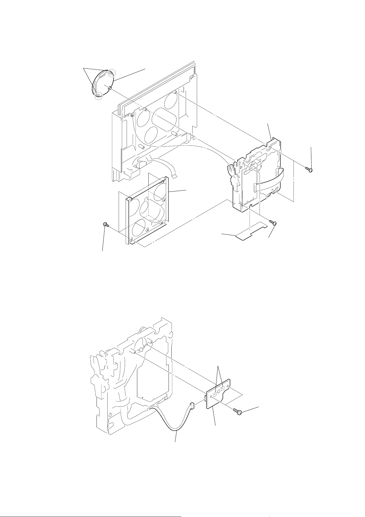
3-17. CD Mechanism (CDM71B)
1
two
claws
2
cap (chuck) assy
7
blacket
8
CD mechanism (CDM71B)
HCD-L7HD
4
two
screws
(+BVTP 2.6
×
8)
3-18. L.MOTOR Board
6
six
screws (+BTP 2.6
×
3
sheet
5
two
screws
×
× 6
8)
)
(+BVTP 2.6
6)
1
Remove solder (two portions ).
2
two
screws
(+BTP 2.6
3
connector
(CN711)
4
L.MOTOR board
19
HCD-L7HD
)
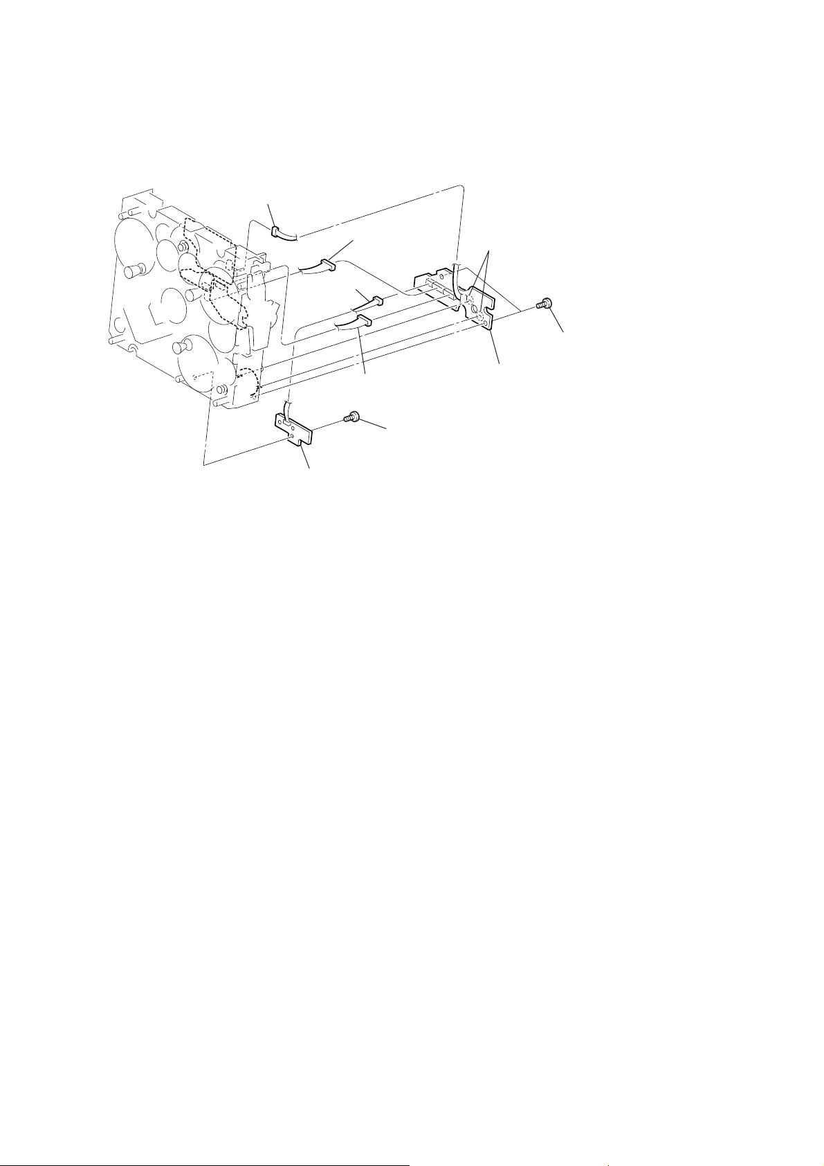
3-19. C.MOTOR Board, L.SENSOR Board
3
connector
(CN711)
5
(CN753)
c
onnector
6
(CN755)
4
c
onnector
(CN754)
c
onnector
8
(+BTP M 2.6
screw
1
Remove solder
(two portions ).
7
C.MOTOR board
×
6)
2
two screws
(+BTP M 2.6
×
6
9
L.SENSOR board (R)
20
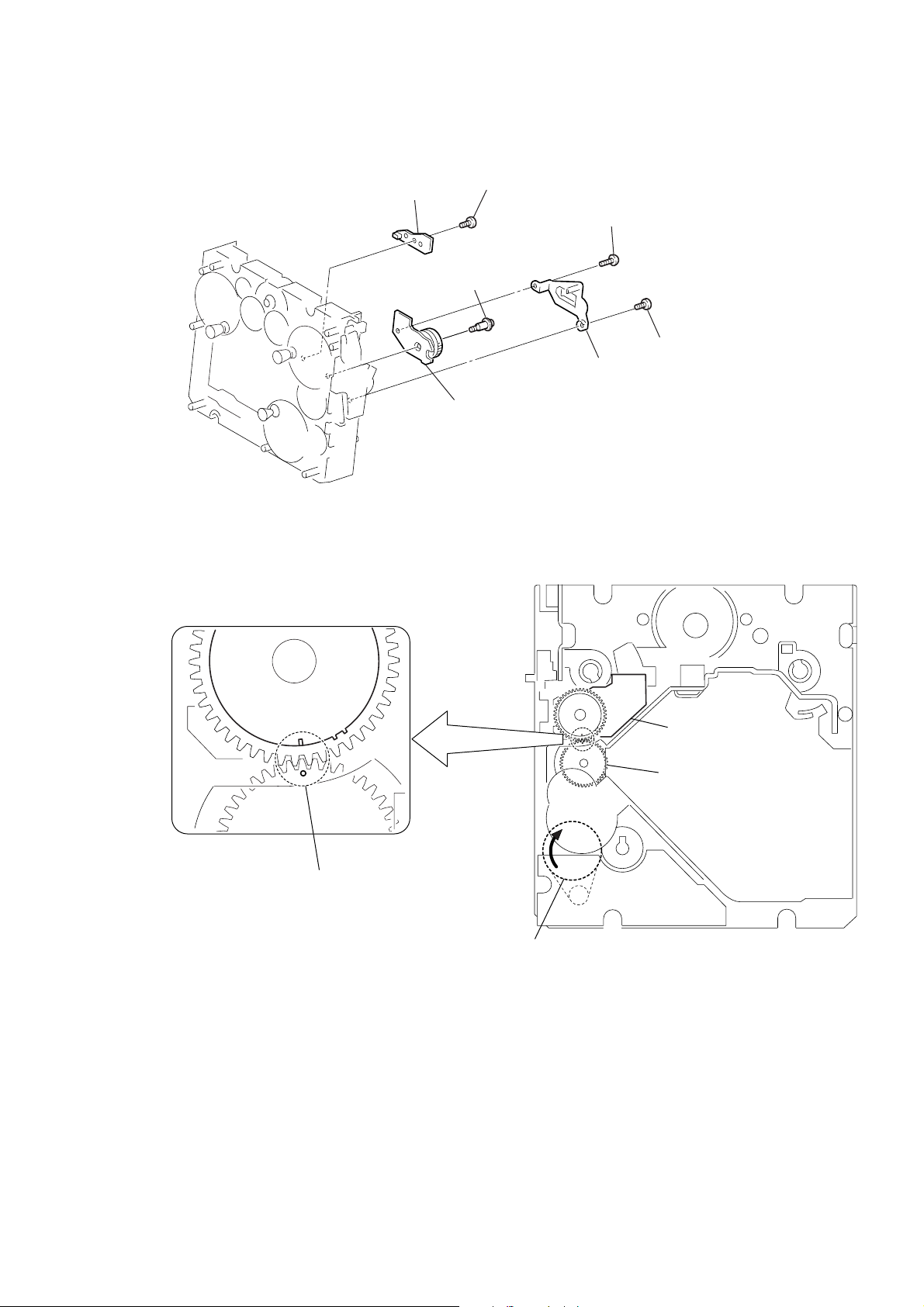
3-20. ENCODER Board, D.SENSOR Board
7
D.SENSOR board
4
6
(+BTP 2.6
screw (+PWH 2
5
ENCODER
screw
×
HCD-L7HD
Ver 1.2 2003.12
×
6)
2
screw (+BTP 2.6
6)
1
3
cover (encoder)
board
(+BTP 2.6
screw
× 8
×
)
6)
PRECAUTION DURING ENCODER board INSTALLATION
Rotate the pulley (LDG2) until the mark of the cam (A) becomes visible.
Install the ENCODER board in the way that it is sandwiched by
the cut-outs of the ENCODER board.
pulley (LDG2)
ENCODER board
cam (A)
21
HCD-L7HD
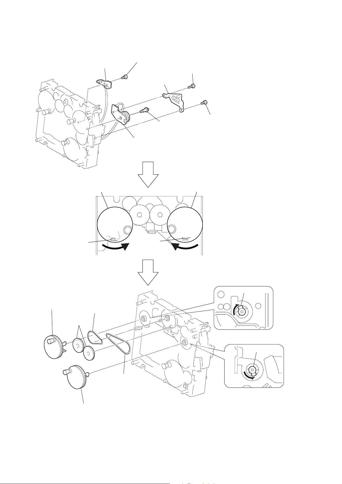
3-21. Pulley (RTR) Assy, Pulley (RTL) Assy, Belt (CDM71), Belt (Roller) (L)
6
screw
7
D.SENSOR board
(+BTP 2.6
5
ENCODER
(When installing it, see the ENCODER board item.)
×
6)
3
cover (encoder)
4
screw (+PWH 2
board
2
screw (+BTP 2.6
×
6)
× 8
1
screw
(+BTP 2.6
×
)
6)
qf
RTL pulley assy
9
qg
gear (S1)
c
law
qh
belt (CDM71)
q;
8
pulley (RTR) assypulley (RTL) assy
c
law
q;
RTL pulley assy
qd
RTR pulley assy
22
qs
RTR pulley assy
qj
belt (ROLLER) (L)
qa
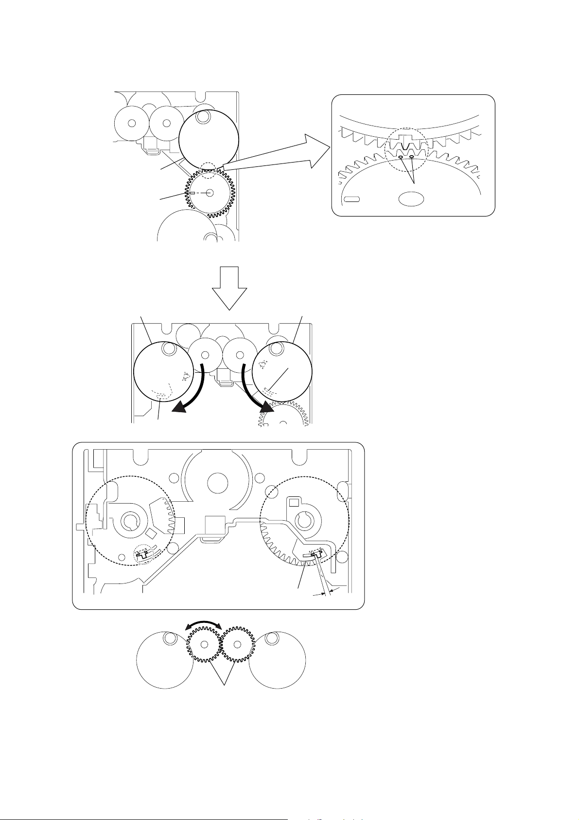
PRECAUTION DURING PULLEY (RTR) ASSY, PULLEY (RTL) ASSY INSTALLATION
pulley (RTR) assy
pulley (RTR) assy
HCD-L7HD
gear (S2)
(9 o'clock position)
pulley (RTL) assy
claw
marks of the gear (S2)
Place the holes of the gear (S2) at the 9 o'clock position and install
the pulley (RTR) assy.
Install it in the way that the gear of the cut-out portion as shown is located in
between the marks of the gear (S2).
pulley (RTR) assy
claw
Then install the pulley (RTL) assy in the way that it can perform
the symmetrical movement with the pulley (RTR) assy.
Then lock both claws.
pulley (RTR) assy
pulley (RTL) assy
Confirm that the pulley (RTR) contacts the claws.
Opposite to it, the pulley (RTL) assy must
have clearance of 1 to 2 mm with the claw.
It should contact with claw.
If clearance is too large or it contacts with claw,
adjustment is necessary.
claw
1 to 2 mm
Method of adjustment is as follows.
Raise the right gear (S1) a little and perform adjustment
by moving the left gear (S1).
gear (S1)
23
HCD-L7HD
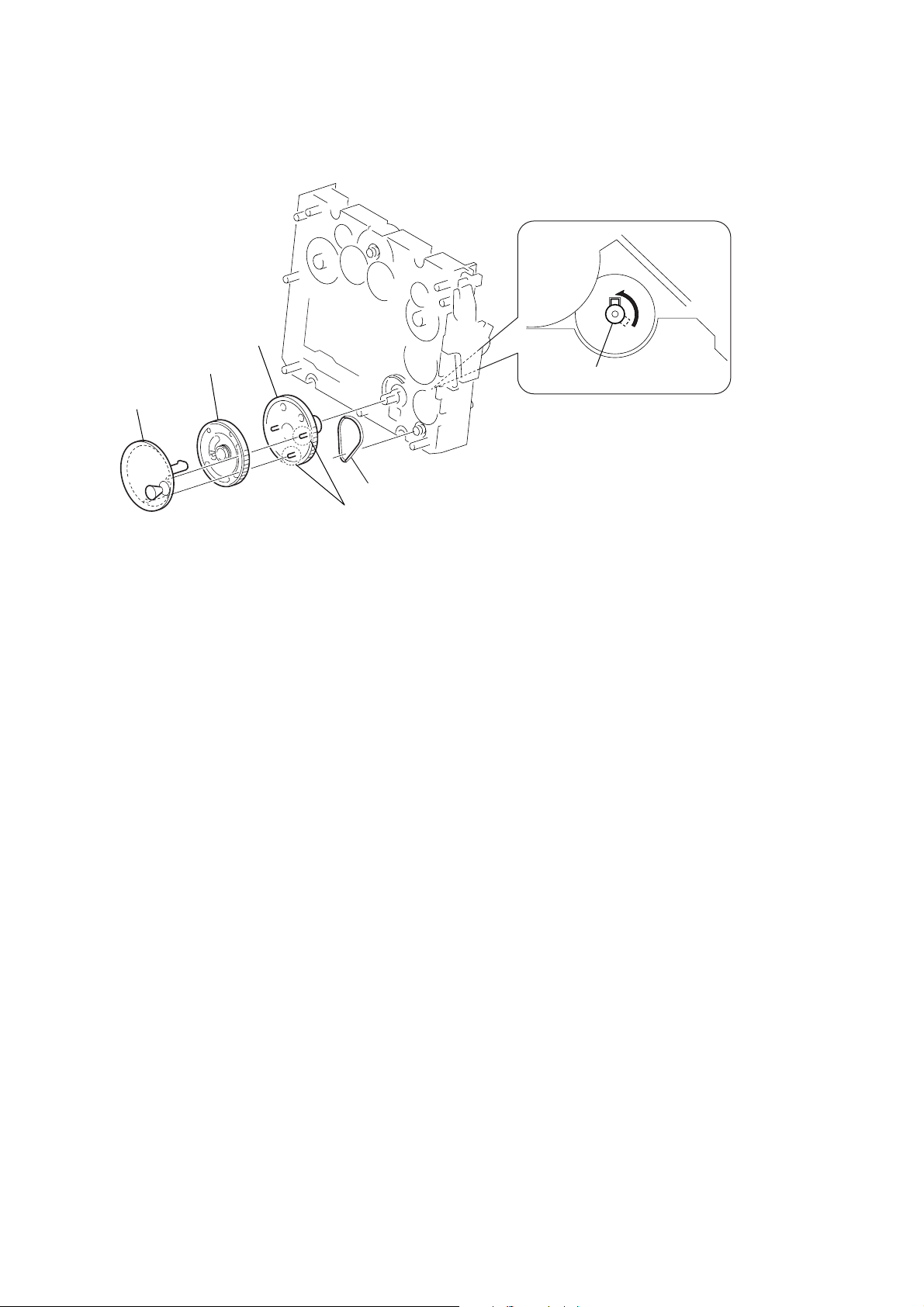
3-22. Pulley (SPT) Assy, Gear (RT) Assy, Gear(KT), Belt (CDM71)
3
2
SPT pulley assy
4
gear (KT)
gear (RT) assy
Rotate the SPT pulley assy in the direction of , and remove your hands
at the position where the shaft agrees with the hole shape on the chassis.
SPT pulley assy
5
belt (CDM71 )
When installing, align the protruded portion of the KT gear with groove of the SPT
pulley assy.
1
1
24
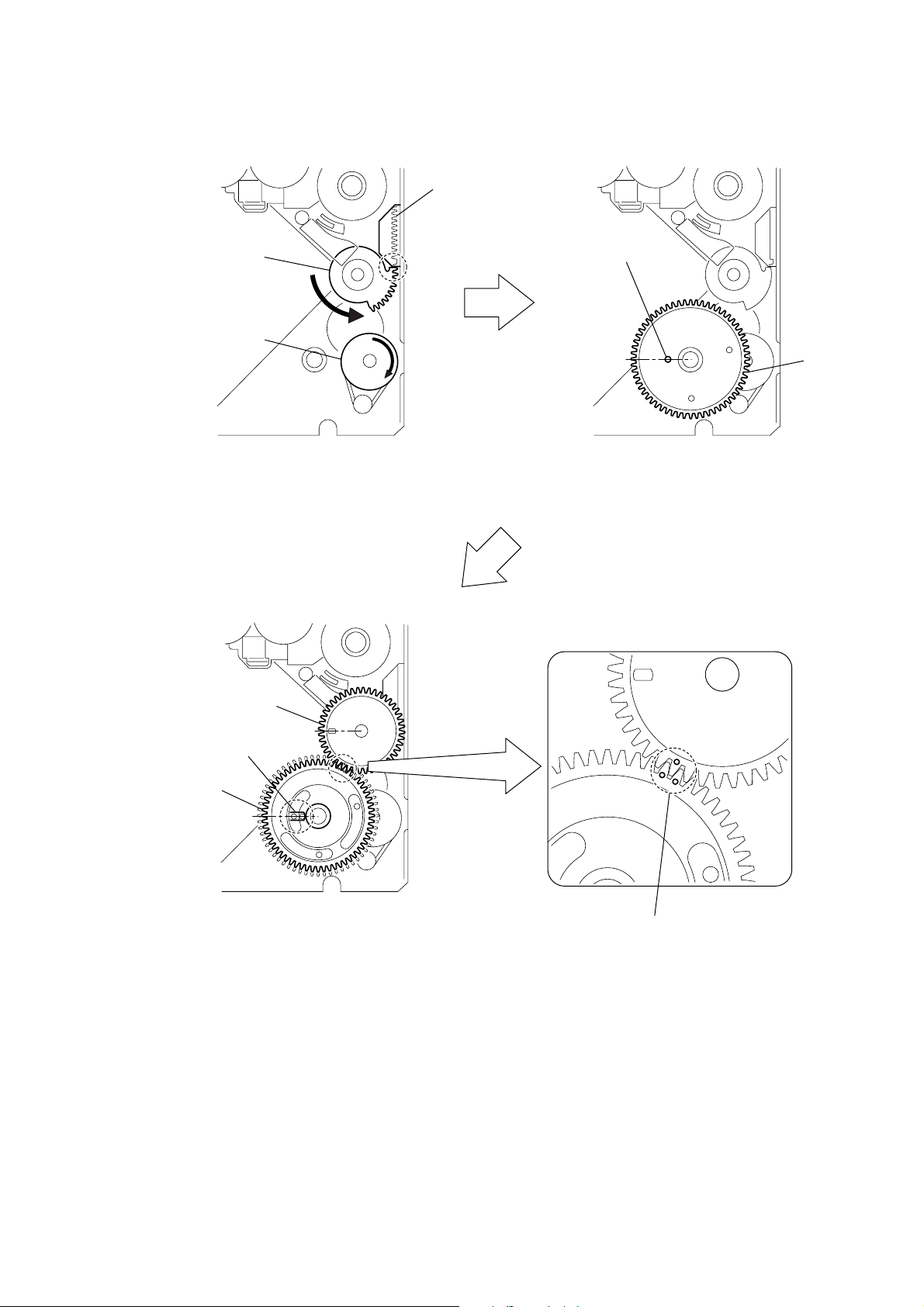
PRECAUTION DURING GEAR (RT) ASSY, GEAR (KT), GEAR (S2) INSTALLATION
gear (KT)
gear (RT) assy
gear (RT) assy
torsion spring (M)
gear (S2)
gear (S2)
pulley (LDG2)
lever (ST)
cam (A)
Confirm that the gear (S2) mark is located
in between the gear (RT) assy marks.
Rotate the pulley (LDG2) until it reaches the position
where the cam (A) contacts with the lever (ST).
Install the gear (KT) and position it so that the boss
that is closest to the inside is located at the 9 o'clock position.
The boss that is closest to the inside
Install the gear (RT) assy so that the two bosses are aligned
in between the torsion spring (M).
Install the gear (S2) so that its hole is located at the 9 o'clock position.
HCD-L7HD
25
HCD-L7HD
SECTION 4
TEST MODE
[Key Check Mode]
* Keyboard check.
Procedure:
1. Press the ?/1 button to turn the set ON.
2. To enter the test mode, press three buttons DISPLA Y , NX
(CD) and > simultaneously.
3. In the key check mode, the fluorescent indicator displays
“KEY00”. Each time a button is pressed, “KEY00” value
increases. However, once a button is pressed, it is no longer
taken into account.
4. T o exit from this mode, press three b uttons DISPLA Y , NX
(CD) and > simultaneously.
[Version Display Mode]
* The version or destination is displayed.
Procedure:
1. Press the ?/1 button to turn the set ON.
2. To enter the test mode, press three buttons DISPLA Y , V OL+
and VOL– simultaneously.
3. The model name and destination are displayed on the upper
line. The STR version is displayed on the lower line.
4. Press the DISPLA Y b utton again. The CD version is displayed.
5. Every pressing of the DISPLAY button displays the versin of
MMI, SH or USB.
6. Press the DISPLAY button. The STR version is displayed
again.
7. To exit from this mode, press the ?/1 button to turn off the set.
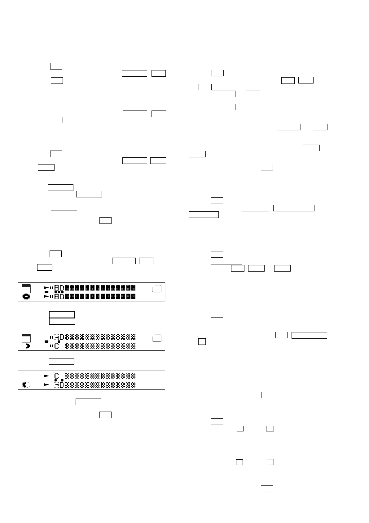
[FL T ube Test Mode]
* All fluorescent segments are tested.
Procedure:
1. Press the ?/1 button to turn the set ON.
2. To enter the test mode, press three buttons DISPLA Y , NX (CD)
and V OL– simultaneously.
3. All segments are turned on.
LIBRARY
AUTO
HIGH
STORAGE
1 ALBUM
ALL
PROGRAM
SHUFFLE
REP
1 L-SYNC
HIGHLIGHT
SEARCH
HISTORY
REC L F P
DISC DSG
ALBUM
TRACK
CD TEXT
L
OVER
R
MANUAL
PRESET
c
REC1 2 3
DAILY
STEREOAUTO
SLEEP
TUNED
MONO
4. Press the DISPLAY button. All segments are turned off.
5. Press the DISPLAY button. Confirm the pattern of segments.
LIBRARY
HIGH
STORAGE
1
PROGRAM
1
HIGHLIGHT
HISTORY
REC F
DISC
ALBUM
TRACK
L
R
c
13
TUNED
AUTO
MONO
6. Press the DISPLAY button. Confirm the pattern of segments.
CD TEXT
OVER
DSG
MANUAL
PRESET
REC 2
DAILY
SLEEP
STEREO
ALL
ALBUM
AUTO
SHUFFLE
REP
SEARCH
L-SYNC
L P
7. Every pressing of the DISPLAY button turns on each segment
one after another in the same order.
8. T o e xit from this mode, press the ?/1 button to turn off the set.
[Amp Test Mode]
* Combinatin of preset equalizer and volume is changed for the
amplifier test.
Procedure:
1. Press the ?/1 button to turn the set ON.
2. T o enter the test mode, press three buttons . , NX (CD)
and > simultaneously.
3. Press the DISPLAY and NX (CD) buttons simultaneouslly.
4. The message “7[TESTMIN]” appears.
5. Press the DISPLAY and NX (CD) buttons simultaneously.
6. The message “8[TESTMID]” appears.
7. The messages “9[TESTMAX]”, “10[TESTSUR]”, “7[TESTMIN]”,
, , are changed by every pressing of the DISPLAY and NX
(CD) buttons simultaneously.
8. Volume level is changeable at three steps as “V OLUME MIN”,
“VOLUME 21”, “VOLUME MAX” by pressing VOL+ or
VOL– button.
9. In this test mode, the tuning mode is set to the preset mode.
10. To exit from this mode, press the ?/1 button to turn off the set.
[Forced Reset]
* All micro-processors are forced to reset at the same time.
Procedure:
1. Press the ?/1 button to turn the set ON.
2. Press three buttons DISPLAY , TUNER/BAND and
FUNCTION simultaneously.
3. The fluorescent indicator tube displays the message “COLD
RESET” and the set is reset. Then the set is turned off.
[CD Ship Position]
Procedure:
1. Press the ?/1 button to turn the set ON.
2. Press the FUNCTION button for the setting CD.
3. Press three buttons . , VOL+ and V OL– simultaneously .
4. The fluorescent indicator tube displays the message “COLD
RESET” and CD is set to the shipment position. Then the set is
turned off.
[Aging Mode]
Procedure:
1. Press the ?/1 button to turn the set ON.
2. Insert the disc.
3. Select the FUNCTION to CD.
4. To enter the test mode, press three buttons . , TUNER/BAND
and Z simultaneously.
5. Aging operation starts automatically.
6. The CD cover opens ,closes and the f irst tr ack is played. Then
the last track is played.
7. The CD cover opens a gain, and the message “ AGIN00000001”
is displayed. This value is cycle times of aging operation and
displays hexadecimal data.
8. The cover closes and aging operation is continued.
9. To exit from this mode, press the ?/1 button to turn off the set.
[Loading Mechanism Lock]
Procedure:
1. Press the ?/1 button to turn the set ON.
2. Press two buttons of x (CD)and Z simultaneously for fiv e
seconds.
3. The message “LOCKED” is displayed and the loading
mechanism is locked. (Even if exiting from this mode, the
loading mechanism is still locked.)
4. Press two b uttons of x (CD) and Z simultaneously for five
seconds again.
5. The message “UNLOCKED” is displayed and the loading
mechanism is unlocked.
6. To exit from this mode, press the ?/1 button to turn the set off.
26
HCD-L7HD
[Error History Display Mode]
Procedure:
Setting Method of Test Mode
1. Press the ?/1 button to turn the set ON.
2. Select the FUNCTION to CD.
3. To enter the test mode, press three buttons . , VOL+ and
> simultaneously.
4. Confirm to display “dvt ERR CODE”.
5. Press the Z button.
Releasing Method of Test Mode
1. Press the x (CD) button to display “dvt ERR CODE”.
2. Press the x (CD) button.
Menu Selection of Error History Display Mode
1. Select the operation in the menu by pressing the . or >
button.
2. Press the Z button. The menu is selected. If returning to the
menu again, press the x (CD) button.
DISPLAY OF TIMES OF ERROR
DISPLAY OF MECHANISM ERROR HISTORY
RESET OF MECHANISM ERROR HISTORY
RESET OF ERROR HISTORY
RESET OF NO DISC ERROR HISTORY
DISPLAY OF NO DISC ERROR HISTORY
" Emc=**Edc=## "
" dvt ECODE MEC "
" dvt ECNT0 MEC "
" dvt ECNT0 ALL "
" dvt ECNT0 BU "
" dvt ECODE BU "
Display of Times of Error
* Number of times of mechanism error and no disc error is displayed
in hexadecimal.
DISPLAY : “ Emc=**Edc=## “
** : number of times of mechanism error (hexadecimal)
## : number of times of no disc error (hexadecimal)
Display of Mechanism Error History
1. Select the operation in the menu by pressing the . or >
button to display “dvt ECODE MEC”.
2. Press the Z button.
3. Select the mechanism error code by pressing the . or >
button.
DISPLAY : “ E**M##%%000000 “
** : order of mechanism error happens (hexadecimal)
00 : the newest error
09 : the error ten times before
## : completion of an initialization (hexadecimal)
ff : completion
others : not completed
%% : condition of CDM operation when the trouble happened
(hexadecimal)
00 : during an initialization
1x : during opening (x : not fixed)
16 to 19 : during a kick by falure of opening
2x : completion of opening
28 : completion of opening under the condition of no disc
3x : during close request
4x : during open request
5x : during closing
6x : during chucking
80 : during releasing
9x : during operation of BU down
ax : during operation of shutter opening or closing
b0 : during BU up request
c0 : during BU down request
dx : during operation of BU up
000000
: fixed
Reset of Mechanism Error History
1. Select the operation in the menu by pressing the . or >
button to display “dvt ECONT0 MEC”.
2. Press the NX (CD) button. Mechanism error history is reset.
Display of No Disc Error History
1. Select the operation in the menu by pressing the . or >
button to display “dvt ECODE BU”.
2. Press the Z button.
3. Select the no disc code by pressing the . or > button.
DISPLAY : “ E**D##%%@@&& “
** : order of no disc happens (hexadecimal)
00 : the newest
09 : ten times before
## : description of the trouble (hexadecimal)
01 : focus NG
02 : GFS NG
03 : time-over of starting
04 : continuous unlock of focus
05 : no input of Q-codes in fixed time
%% : condition when the trouble happened (hexadecimal)
01 : during shipment position processing
02 : during power off processing
03 : during processing of initialization
04 : during stop condition
05 : during stop processing
06 : during process of starting
07 : during process of TOC reading
08 : during search operation
09 : during playback
0a : during pause
0b : during playback manual searching
0c : during pause manual searching
@@ : do not care
&& : rotating speed of a disc when the trouble happened
(hexadecimal)
01 : x1
02 : x2 (double speed)
03 : x4
27
HCD-L7HD
Reset of No Disc Error History
1. Select the operation in the menu by pressing the . or >
button to display “dvt ECONT0 BU”.
2. Press the NX (CD) button. No disc error history is reset.
Reset of Error History
1. Select the operation in the menu by pressing the . or >
button to display “dvt ECONT0 ALL”.
2. Press the NX (CD) button. Error history is reset.
[Servo T est Mode]
*Error Rate Display
Procedure:
Setting Method of Test Mode
1. Press the ?/1 button to turn the set ON.
2. Insert the disc.
3. Select the FUNCTION to CD.
4. Press the NX (CD) button to play the CD.
5. To enter the test mode, press three buttons DISPLAY , VOL+
and FUNCTION simultaneously.
6. Press the . or > button to display “dvt ERR RATE”.
7. Press the Z button.
Description of Error Rate
" ****####%%@@&& "
C1 C2 TNO MIN SEC
HD SECTION
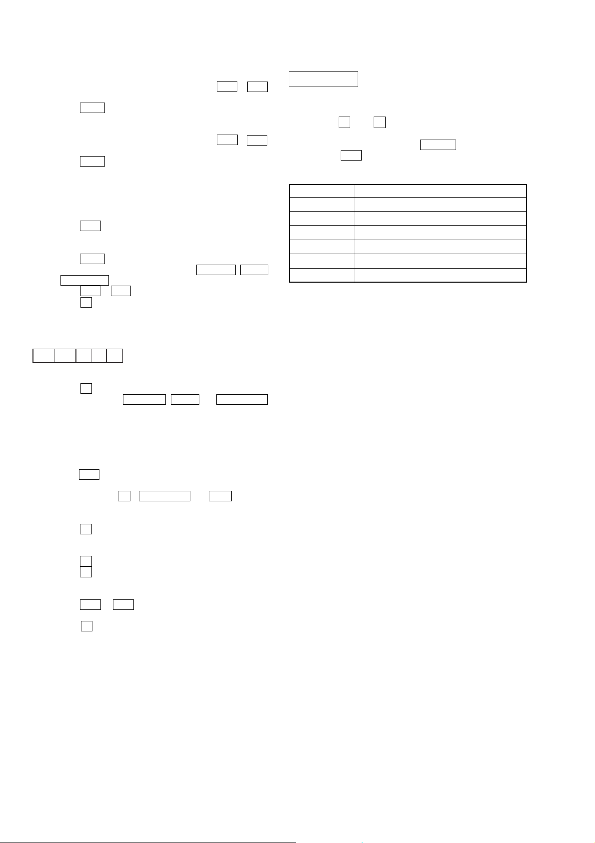
[HD Test Mode]
Procedure:
1. Press the x (CD), x (HD) and FUNCTION simultaneously .
2. The message “Format?” is displayed.
3. Select the menu by rotating the ALBUM dial.
4. Press the > button to execute the HD test.
HD Test Menu
Display Function
Format?Formatting the HD
Flash Init? Initialization of Flash
Read Test? Sector read test of the HD
Write Test? Sector write test of the HD
R/W Test? Sector write/read and verify test of the HD
Smart? Display of S.M.A.R.T. status
Releasing Method of Test Mode
1. Press the x (CD) button to display “dvt ERR RATE”.
2. Press three buttons DISPLAY , VOL+ and FUNCTION
simultaneously.
[CD Repeat 5 Times Limit Release Mode]
Procedure:
Setting Method of Test Mode
1. Press the ?/1 button to turn the set ON.
2. Select the FUNCTION to CD.
3. Press three buttons Z , VOLUME + and . simulta-
neously.
4. The message “dvt REP LMT” is displayed.
5. Press the Z button.
Releasing Method of Test Mode
1. Press the x (CD) button to display “dvt REP LMT”
2. Press the x (CD) button.
Selection of Repeat 5 Times Limit ON/OFF
1. Press the . or > button to display “REP LMT ON” or
“REP LMT OFF”.
2. Press the x (CD)button to select ON or OFF and “dvt REP
LMT” is displayed.
28
HCD-L7HD
Note :
If any of the following test modes is ex ecuted, data is written in the
HD.
Never execute an y of these test modes on the customer's HD, because
customer's data is erased during test mode.
1. FORMAT
4. WRITE TEST
5. R/W TEST
HD Aging Test
Note (When HD is replaced) :
When HD is replaced, perform the following steps.
(a) When HD is replaced, leave the set with the power on for
approximately thirty minutes . (Warming up the HD)
(b) Enter the HD test mode and format the HD.
(c) Turn off the power once and back on again.
(d) Record the music in the HD using CD-HDD Synchro-
Recording function for testing the HD. (about thirty minutes)
(e) Confirm that music is correctly recorded. After it is confirmed,
erase all recordings on the HD.
1. FORMAT
* This mode performs logical formatting HD. (about three minutes)
If formatting is performed, all data on the HD is erased.
*When HD is replaced, be sure to format the new HD. If the new
HD is not formatted, the error message "Format Error " will be
displayed.
*The 500 albums and 10 play lists are created at the same time of
logical formatting FAT32 on the HD.
Procedure:
(1) Enter the HD test mode, then rotate the ALBUM dial to display
“Format?”, and press the > button to display “F ormat OK?”.
(2) When the > button is pressed, The message “Format Now”
is displayed and it takes about three minutes.
(3) When format is complete, “Format End” is displayed.
(4) To exit from this mode, press the x (HD) button.
2. FLASH INITIALIZATION
*The last memory (which is stored before power-off) is initialized
to the default value of the factory setting.
Procedure:
(1) Enter the HD test mode, then rotate the ALBUM
“Flash Init?”, and press the > button.
(2) Initialization is performed and “OK” is displayed.
(3) To exit from this mode, press the x (HD) button.
Contents of the Last memory
Item Contents Default value
L.Sync Setup Level Syncro ON/OFF ON
L.Sync Th IDX Level-Sync THRESH value 50dB
S.Space Setup Smart Space ON/OFF ON
Text Save Setup TEXT SAVE ON/OFF ON
1/ALL Play mode of ALBUM ALL
PLAY MODE Play mode CONTINUE
REP MODE Repeat mode OFF
Display Mode Time Display mode Total playing time
Current Album No. The present Album Number 1
Album Favorite
History Playback history of Album None
ALBUM No. of Album Favorites
A to E
dial to display
No Assign
3. READ TEST
* This mode needs not be performed in normal operation.
*Perform this mode only for the newly formatted HD.
Procedure:
(1) Enter the HD test mode, then rotate the ALBUM dial to display
“Read Test?”, and press the > button to display “IN”.
“MID”, “OUT” or “THRU” is also selectable by rotating the
ALBUM dial.
(2) Press the > button and “T esting xx %” is displayed during
the read test.
(3) When the read test is good, “OK” will be displayed.
(4) To exit from this mode, press the x (HD) button.
* “THRU” test takes very long time.
4. WRITE TEST
* This mode needs not be performed in normal operation.
*Perform this mode only for the newly formatted HD.
Procedure:
(1) Enter the HD test mode, then rotate the ALBUM dial to display
“Write Test?”, and press the > button to display “IN”.
“MID”, “OUT” or “THRU” is also selectable by rotating the
ALBUM dial.
(2) Press the > button and “T esting xx %” is displayed during
the write test.
(3) When the write test is good, “OK” will be displayed.
(4) To exit from this mode, press the x (HD) button.
* “THRU” test takes very long time.
5. R/W TEST
*Perform the R/W TEST when checking the formatted HD.
* Confirmation is normally satisfied by each performing IN, MID
and OUT sector test.
Procedure:
(1) Enter the HD test mode, then rotate the ALBUM
“R/W Test?”, and press the > button to display “IN”.
“MID”, “OUT” or “THRU” is also selectable by rotating the
ALBUM dial.
(2) Press the > button and “T esting xx %” is displayed during
the R/W test.
(3) When the R/W test is good, “OK” will be displayed.
(4) To exit from this mode, press the x (HD) button.
* “THRU” test takes very long time.
6. SMART TEST
*This mode displayed status of S.M.A.R.T. functions of the HD.
* If "NG" appears in this mode, the HD may be damaged in the
near future. Replacement of the HD is recommended.
Procedure:
(1) Enter the HD test mode, then rotate the ALBUM dial to display
“Smart?”, and press the > button.
(2) When the test is complete, “OK” or “NG” is displayed.
(3) To exit from this mode, press the x (HD) button.
dial to display
29