

Sony HCD-HDX277WC, HCD-HDX275, HCD-HDX675, HCD-HDX576WF, HCD-HDX279W Service Manual
...
HCD-HDX275/HDX277WC/HDX279W/
HDX475/HDX576WF/HDX675
Q
Q
3
7
6
3
1
5
1
5
0
SERVICE MANUAL
Ver. 1.1 2008.05
TEL 13942296513 QQ 376315150 892498299
Photo: HCD-HDX275
• HCD-HDX275 is the amplifier section, super
audio CD/DVD system, tuner section and
video section in DAV-HDX275.
• HCD-HDX277WC is the amplifier section,
super audio CD/DVD system, tuner section
and video section in DAV-HDX277WC.
• HCD-HDX279W is the amplifier section,
super audio CD/DVD system, tuner section
and video section in DAV-HDX279W.
• HCD-HDX475 is the amplifier section, super
TEL
13942296513
audio CD/DVD system, tuner section and
video section in DAV-HDX475.
• HCD-HDX576WF is the amplifier section,
super audio CD/DVD system, tuner section
and video section in DAV-HDX576WF.
• HCD-HDX675 is the amplifier section, super
audio CD/DVD system, tuner section and
video section in DAV-HDX675.
This product incorporates copyright protection technology that is
protected by U.S. patents and other intellectual property rights.
Use of this copyright protection technology must be authorized by
Macrovision, and is intended for home and other limited viewing
uses only unless otherwise authorized by Macrovision. Reverse
engineering or disassembly is prohibited.
This system incorporates with Dolby* Digital and Dolby Pro Logic (II) adaptive matrix surround decoder and the DTS** Digital
Surround System.
* Manufactured under license from Dolby Laboratories.
“Dolby”, “Pro Logic”, and the double-D symbol are trade-
marks of Dolby Laboratories.
** Manufactured under license from DTS, Inc.
“DTS” and “DTS Digital Surround” are registered trademarks
of DTS, Inc.
This system incorporates High-Defi nition Multimedia Interface
(HDMITM) technology.
HDMI, the HDMI logo and High-Defi nition Multimedia Interface
are trademarks or registered trademarks of HDMI Licensing LLC.
“BRAVIA” and are trademarks of Sony Corporation.
“S-AIR” and its logo are trademarks of Sony Corporation.
Q
AUDIO POWER SPECIFICATIONS
for the US model
POWER OUTPUT AND TOTAL HARMONIC
DISTORTION:
With 3 ohms loads, both channels
Amplifi er Section (EXCEPT HCD-HDX279W/HDX576WF)
Surround mode (reference) RMS output power
FL/FR/C/SL/SR*: 143 watts (per
Subwoofer*: 285 watts (at 1.5
Amplifi er Section (HCD-HDX279W/HDX576WF)
Surround mode (reference) RMS output power
FL/FR/C*: 143 watts (per channel
Subwoofer*: 285 watts (at 1.5
* Depending on the decoding mode settings and the source,
there may be no sound output.
Inputs (Analog)
TV/VIDEO (AUDIO IN) (EXCEPT HCD-HDX576WF)
Sensitivity: 450/250 mV
TV (AUDIO IN) (HCD-HDX576WF)
Sensitivity: 450/250 mV
SAT/CABLE (AUDIO IN) (HCD-HDX576WF)
Sensitivity: 450/250 mV
AUDIO IN Sensitivity: 250/125 mV
Q
driven, from 180 - 20,000 Hz; rated
84 watts per channel minimum
RMS power, with no more than
0.7% total harmonic distortion from
250 milli watts to rated output.
channel at 3 ohms, 1 kHz, 10%
THD)
ohms, 80 Hz, 10% THD)
at 3 ohms, 1 kHz, 10% THD)
ohms, 80 Hz, 10% THD)
Model Name Using Similar Mechanism HCD-HDX265
DVD Mechanism Type CDM81C-DVBU101
Optical Pick-up Block Name
7
3
9
8
SPECIFICATIONS
5
1
3
6
2
4
9
8
2
9
US Model
HCD-HDX275/HDX277WC/
HDX279W/HDX576WF
Canadian Model
HCD-HDX475/HDX576WF/HDX675
E Model
Australian Model
HCD-HDX275
KHM-310CAB or
KHM-313CAB
9
2
8
9
4
2
9
8
0
5
1
Inputs (Digital)
TV/VIDEO (COAXIAL IN/OPTICAL IN) (EXCEPT HCDHDX576WF) Impedance: 75 ohms/TV (COAXIAL IN/OPTICAL IN) (HCD-HDX576WF)
Impedance: 75 ohms/Outputs (Analog)
Phones Accepts low- and high-impedance
Super Audio CD/DVD System
Laser Semiconductor laser
(Super Audio CD/DVD: λ = 650
(CD: λ = 790 nm)
Emission duration: continuous
Signalformat system NTSC
Tuner Section
System PLL quartz-locked digital synthe-
FM tuner section
Tuning range
North American models: 87.5 MHz - 108.0 MHz (100 kHz
Other models: 87.5 MHz - 108.0 MHz (50 kHz
Antenna (aerial) FM wire antenna (aerial)
Antenna (aerial) terminals 75 ohms, unbalanced
Intermediate frequency 10.7 MHz
AM tuner section
Tuning range
North American, Mexican, and Latin American
models:
530kHz - 1,710kHz (with the
531kHz - 1,710kHz (with the
headphones.
nm)
sizer
step)
step)
interval set at 10kHz)
interval set at 9kHz)
– Continued on next page –
9
TEL 13942296513 QQ 376315150 892498299
9
w
w
9-887-987-02
2008E05-1
©
w
2008.05
.
xia
Sony Corporation
Audio Business Group
Published by Sony Techno Create Corporation
o
y
u
1
6
3
.
c
o
DVD RECEIVER
m
HCD-HDX275/HDX277WC/HDX279W/HDX475/HDX576WF/HDX675
European, CIS and Middle Eastern models:
531kHz - 1,602 kHz (with the interval
Q
Q
Australian and New Zealand models:
531kHz - 1,710 kHz (with the interval
530kHz - 1,710 kHz (with the interval
Other models: 531kHz - 1,602 kHz (with the interval
530kHz - 1,610 kHz (with the interval
Antenna (aerial) AM loop antenna (aerial)
Intermediate frequency 450 kHz
Video Section
Outputs VIDEO: 1 Vp-p 75 ohms
COMPONENT:
Y: 1 Vp-p 75ohms
P
75 ohms
HDMI OUT: Type A (19 pin)
General
Power requirements
North American models: 120 V AC, 60 Hz
TEL 13942296513 QQ 376315150 892498299
Other models: 220 V - 240 V AC, 50/60 Hz
Power consumption
HCD-HDX275/HDX277WC/HDX475/HDX675
On: 165 W
Standby: 0.3 W (at the
Power Saving mode)
HCD-HDX279W/HDX576WF
On: 125 W
Standby: 0.3 W (at the
Power Saving mode)
Output voltage (DIGITAL MEDIA PORT)
DC 5 V
Output current (DIGITAL MEDIA PORT)
700 mA
Dimensions (approx.) 430 mm × 85 mm × 420
mm (17 in × 3
16
projecting parts
Mass (approx.) 5.2 kg (11 lb 8 oz)
Design and specifi cations are subject to change without notice.
TEL
set at 9 kHz)
7
3
set at 9 kHz)
set at 10 kHz)
set at 9 kHz)
set at 10 kHz)
B/CB, PR/CR: 0.7Vp-p
5
/8 in) (w/h/d) incl.
6
3
/8 in ×
3
1
13942296513
5
1
5
Notes on chip component replacement
• Never reuse a disconnected chip component.
0
• Notice that the minus side of a tantalum capacitor may be damaged by heat.
CAUTION
Use of controls or adjustments or performance of procedures other than
those specifi ed herein may result in hazardous radiation exposure.
SAFETY CHECK-OUT
After correcting the original service problem, perform the following safety check before releasing the set to the customer:
Check the antenna terminals, metal trim, “metallized” knobs,
screws, and all other exposed metal parts for AC leakage.
Check leakage as described below.
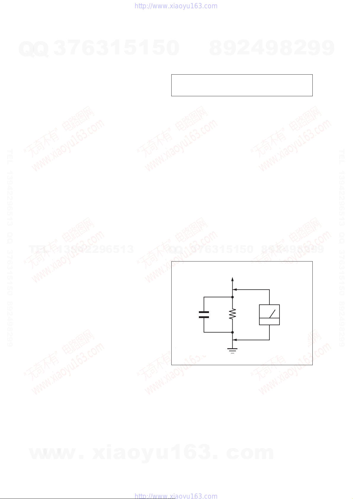
LEAKAGE TEST
The AC leakage from any exposed metal part to earth ground and
from all exposed metal parts to any exposed metal part having a
return to chassis, must not exceed 0.5 mA (500 microamperes.).
Leakage current can be measured by any one of three methods.
1. A commercial leakage tester, such as the Simpson 229 or RCA
WT-540A. Follow the manufacturers’ instructions to use these
instruments.
2. A battery-operated AC milliammeter. The Data Precision 245
digital multimeter is suitable for this job.
3. Measuring the voltage drop across a resistor by means of a
VOM or battery-operated AC voltmeter . The “limit” indication
is 0.75 V, so analog meters must have an accurate low-voltage
scale. The Simpson 250 and Sanwa SH-63Trd are examples
of a passive VOM that is suitable. Nearly all battery operated
digital multimeters that have a 2 V AC range are suitable. (See
7
3
Q
Q
Fig. A)
8
6
3
9
1
5
2
1
5
4
0
9
8
9
8
2
4
2
9
8
9
2
9
9
TEL 13942296513 QQ 376315150 892498299
9
SAFETY-RELATED COMPONET WARNING!
COMPONENTS IDENTIFIED BY MARK 0 OR DOTTED LINE
WITH MARK 0 ON THE SCHEMATIC DIAGRAMS AND IN
THE PARTS LIST ARE CRITICAL TO SAFE OPERATION.
REPLACE THESE COMPONENTS WITH SONY PARTS
WHOSE PART NUMBERS APPEAR AS SHOWN IN THIS
MANUAL OR IN SUPPLEMENTS PUBLISHED BY SONY.
ATTENTION AU COMPOSANT AYANT RAPPORT
LES COMPOSANTS IDENTIFIÉS PAR UNE MARQUE 0 SUR
LES DIAGRAMMES SCHÉMATIQUES ET LA LISTE DES
PIÈCES SONT CRITIQUES POUR LA SÉCURITÉ DE FONCTIONNEMENT. NE REMPLACER CES COM- POSANTS QUE
w
PAR DES PIÈCES SONY DONT LES NUMÉROS SONT DONNÉS DANS CE MANUEL OU DANS LES SUPPLÉMENTS
PUBLIÉS PAR SONY.
w
À LA SÉCURITÉ!
w
.
xia
o
y
u
To Exposed Metal
Parts on Set
AC
1.5 kΩ0.15 μF
Earth Ground
Fig. A. Using an AC voltmeter to check AC leakage.
1
6
3
.
c
o
m
voltmeter
(0.75 V)
2
Q
HCD-HDX275/HDX277WC/HDX279W/HDX475/HDX576WF/HDX675
SELF DIAGNOSIS FUNCTION
7
Q
3
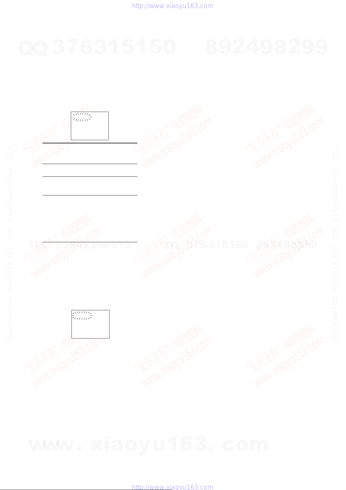
(When letters/numbers appear in the
display)
When the self-diagnosis function is activated to
prevent the system frommalfunctioning, a 5character service number (e.g., C 13 50) with a
combination of a letter and 4 digits appears on
the TV screen or front paneldisplay.In this case,
check the follow i ng table.
6
C:13:50
3
1
5
1
5
0
8
9
2
4
9
8
2
9
9
TEL 13942296513 QQ 376315150 892498299
First 3
characters of
the service
number
C13 Thediscisdirty.
C 31 The disc is not inserted correctly.
EXX
(XX is a
number)
TEL
13942296513
When displaying the version
number on the TV screen
When you turn on the system, the version
number [VER.X.XX] (X is a number) may
appear on th e TV screen. Although this i s not a
malfunction and for Sony service use only,
normal sys tem operation will not be possible.
Turn off the system, and then turn on thesystem
again to operate.
Cause and/or corrective action
Clean the disc with a soft cloth.
Restartthesystem,then re-insert
the disc correctly.
To prevent a malfunction, the
system has performed the selfdiagnosis function.
Contact your nearest Sony
dealer or local authorized Sony
service facility and give the 5character service number.
Example: E 61 10
Q
Q
3
7
6
3
1
5
1
5
0
8
9
2
4
9
8
2
9
TEL 13942296513 QQ 376315150 892498299
9
w
w
w
VER.X.XX
.
xia
o
y
u
1
6
3
.
c
o
m
3

HCD-HDX275/HDX277WC/HDX279W/HDX475/HDX576WF/HDX675
TABLE OF CONTENTS
7
Q
Q
1. SERVICING NOTES ............................................. 5
2. GENERAL .................................................................. 9
3. DISASSEMBLY
3-1. Disassembly Flow ........................................................... 12
3-2. Case (DCR) ..................................................................... 13
3-3. Front Panel Block ........................................................... 13
3-4. POWER Board ................................................................ 14
3-5. Back Panel Block (HDX275/HDX475/HDX675) .......... 14
3-6. Back Panel Block
(HDX277WC/HDX279W/HDX576WF) ....................... 15
3-7. SPEAKER Board, SERIPARA Board and
MAIN Board ................................................................... 15
TEL 13942296513 QQ 376315150 892498299
3-8. Cover (CDM-DCR) ........................................................ 16
3-9. DVD Mechanism Deck (CDM81C-DVBU101) ............. 16
3-10. Tray (Main) Assy ............................................................ 17
3-11. MOTOR Board ............................................................... 17
3-12. Optical Pick-up Section .................................................. 18
3-13. Optical Pick-up Block
(KHM-310CAB or KHM-313CAB) ............................... 18
3-14. Gear (Sub Tray 1)/Gear (Sub Tray 2) ............................. 19
3-15. Lever (Mode) .................................................................. 19
3-16. Stocker Block .................................................................. 20
3-17. Cam (Stocker) ................................................................. 20
3-18. Gear (Stocker 3) .............................................................. 21
3-19. Rotary Encoder (MD) (S771) ......................................... 21
3-20. Gear (BU1) ..................................................................... 22
4. TEST MODE ............................................................ 23
TEL
5. ELECTRICAL ADJUSTMENTS ........................ 27
6. DIAGRAMS
6-1. Block Diagram - RF SERVO/VIDEO Section - ............. 28
6-2. Block Diagram
- CHANGER/HDMI/DMPORT Section - ...................... 29
6-3. Block Diagram - TUNER/S-AIR Section - .................... 30
6-4. Block Diagram - AMP Section - ..................................... 31
6-5. Block Diagram
- PANEL/POWER SUPPLY Section - ............................ 32
6-6. Printed Wiring Board
- MAIN Board (Component Side) - ................................ 34
6-7. Printed Wiring Board
- MAIN Board (Conductor Side) - .................................. 35
6-8. Schematic Diagram - MAIN Board (1/12) - ................... 36
6-9. Schematic Diagram - MAIN Board (2/12) - ................... 37
6-10. Schematic Diagram - MAIN Board (3/12) - ................... 38
6-11. Schematic Diagram - MAIN Board (4/12) - ................... 39
6-12. Schematic Diagram - MAIN Board (5/12) - ................... 40
6-13. Schematic Diagram - MAIN Board (6/12) - ................... 41
6-14. Schematic Diagram - MAIN Board (7/12) - ................... 42
6-15. Schematic Diagram - MAIN Board (8/12) - ................... 43
6-16. Schematic Diagram - MAIN Board (9/12) - ................... 44
6-17. Schematic Diagram - MAIN Board (10/12) - ................. 45
6-18. Schematic Diagram - MAIN Board (11/12) - ................. 46
6-19. Schematic Diagram - MAIN Board (12/12) - ................. 47
6-20. Printed Wiring Board - SERIPARA Board - ................... 47
6-21. Schematic Diagram - SERIPARA Board - ...................... 48
6-22. Printed Wiring Board - S-AIR CON Board
(HDX275/HDX475/HDX675) - ..................................... 49
6-23. Schematic Diagram - S-AIR CON Board
w
(HDX275/HDX475/HDX675) - ..................................... 49
3
13942296513
w
w
6
.
1
3
xia
5
o
1
y
5
u
0
6-24. Printed Wiring Board - S-AIR INC Board
(HDX277WC/HDX279W/HDX576WF) - ..................... 50
6-25. Schematic Diagram - S-AIR INC Board
(HDX277WC/HDX279W/HDX576WF) - ..................... 51
6-26. Printed Wiring Board
- I/O Board (Component Side) - ..................................... 52
6-27. Printed Wiring Board
- I/O Board (Conductor Side) - ....................................... 53
6-28. Schematic Diagram - I/O Board - ................................... 54
6-29. Printed Wiring Board - SPEAKER Board - .................... 55
6-30. Schematic Diagram - SPEAKER Board - ....................... 55
6-31. Printed Wiring Boards - JACK-KEY Section - .............. 56
6-32. Schematic Diagram - JACK-KEY Section - ................... 57
6-33. Printed Wiring Boards - RELAY Section - ..................... 58
6-34. Schematic Diagram - RELAY Section - ......................... 59
6-35. Printed Wiring Board - FL Board - ................................. 60
6-36. Schematic Diagram - FL Board - .................................... 61
6-37. Printed Wiring Board - POWER Board - ........................ 62
6-38. Schematic Diagram - POWER Board - .......................... 63
7. EXPLODED VIEWS
7-1. Case Section .................................................................... 81
7-2. Front Panel Section ......................................................... 82
7-3. Chassis Section ............................................................... 83
7-4. DVD Mechanism Deck Section-1
(CDM81C-DVBU101) ................................................... 84
7-5. DVD Mechanism Deck Section-2
(CDM81C-DVBU101) ................................................... 85
7-6. DVD Mechanism Deck Section-3
(CDM81C-DVBU101) ................................................... 86
7-7. Optical Pick-up Section .................................................. 87
Q
Q
8. ELECTRICAL PARTS LIST .............................. 88
1
6
3
6
7
3
8
3
.
9
1
5
c
2
1
0
5
o
4
8
m
9
9
8
2
4
2
9
8
9
2
9
9
TEL 13942296513 QQ 376315150 892498299
9
4
HCD-HDX275/HDX277WC/HDX279W/HDX475/HDX576WF/HDX675
SECTION 1
SERVICING NOTES
Ver. 1.1
NOTES ON HANDLING THE OPTICAL PICK-UP
Q
TEL 13942296513 QQ 376315150 892498299
BLOCK OR BASE UNIT
Q
The laser diode in the optical pick-up block may suffer electrostatic break-down because of the potential difference generated by the
charged electrostatic load, etc. on clothing and the human body.
During repair, pay attention to electrostatic break-down and also
use the procedure in the printed matter which is included in the
repair parts.
The fl exible board is easily damaged and should be handled with
care.
NOTES ON LASER DIODE EMISSION CHECK
The laser beam on this model is concentrated so as to be focused
on the disc refl ective surface by the objective lens in the optical
pickup block. Therefore, when checking the laser diode emission,
observe from more than 30 cm away from the objective lens.
UNLEADED SOLDER
Boards requiring use of unleaded solder are printed with the leadfree mark (LF) indicating the solder contains no lead.
(Caution: Some printed circuit boards may not come printed with
Unleaded solder has the following characteristics.
• Unleaded solder melts at a temperature about 40 °C higher
than ordinary solder.
Ordinary soldering irons can be used but the iron tip has to be
applied to the solder joint for a slightly longer time.
Soldering irons using a temperature regulator should be set to
TEL
about 350 °C.
Caution: The printed pattern (copper foil) may peel away if the
• Strong viscosity
Unleaded solder is more viscous (sticky, less prone to fl ow)
than ordinary solder so use caution not to let solder bridges
occur such as on IC pins, etc.
• Usable with ordinary solder
It is best to use only unleaded solder but unleaded solder may
also be added to ordinary solder.
7
3
the lead free mark due to their particular size)
: LEAD FREE MARK
6
3
1
5
13942296513
heated tip is applied for too long, so be careful!
1
5
0
Q
Q
NOTE OF REPLACING THE IC1103 ON THE MAIN
BOARD
IC1103 on the MAIN board cannot exchange with single. When
IC1103 on the MAIN board is damaged, exchange the entire
mounted board.
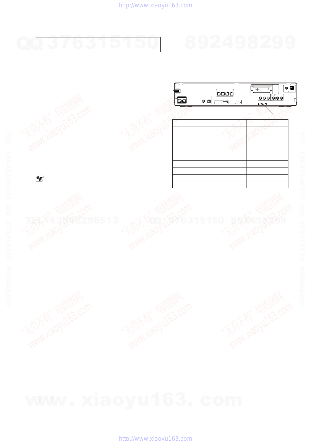
MODEL IDENTIFICATION
CENTER SUBWOOFER
HDX576WF: Canadian model
HDX576WF: US model
HDX277WC
HDX675
HDX275: US model
HDX275: Australian model
HDX275: 240V AC area in E model
HDX475
HDX279W
7
3
SPEAKER
6
8
3
4
2
9
SPEAKER
FRONT R FRONT L SUR R SUR L
TV/VIDEO
DIGITAL IN
HDMI OUT
COAXIAL OPTICAL
Model Part No.
8
0
5
1
5
1
9
DMPORT
DC5V
0.7A MAX
9
8
2
4
2
9
EZW-T100
COMPONENT VIDEO OUT
3-277-790-0[]
3-278-578-3[]
3-278-578-4[]
3-278-578-5[]
3-278-578-7[]
3-278-578-8[]
3-278-579-0[]
3-278-579-3[]
3-278-579-4[]
8
9
TV/VIDEO
VIDEO
OUT
P
B/CB PR/CR AUDIO INYRL
PART NO.
9
2
9
COAXIAL 75
9
ANTENNA
FM
AM
TEL 13942296513 QQ 376315150 892498299
RELEASING THE TRAY LOCK
The disc tray lock function for the antitheft of an demonstration
disc in the store is equipped.
Releasing Procedure:
1. Press the [
2. Press the [FUNCTION] button repeatedly to select “DVD”.
3. While pressing the [
LOCKED” displayed on the fl uorescent indicator tube (around
5 seconds).
Note: When “LOCKED” is displayed, the tray lock is not released by
turning power on/off with the [?/1] button.
RELEASING THE DEMO PLAY LOCK
Releasing Procedure:
1. Press the [
2. Press the [FUNCTION] button repeatedly to select “DVD”.
3. While pressing the [
“DEMO OFF” displayed on the fl uorescent indicator tube
(around 5 seconds).
w
w
w
Note: When “DEMO ON” is displayed, the set is not possible to turn off
the system.
] button to turn on the system.
?/1
] button, press the [A] button until “UN-
s
] button to turn on the system.
?/1
] button, press the [H] button until
s
.
xia
o
y
u
1
6
3
.
c
o
m
5
HCD-HDX275/HDX277WC/HDX279W/HDX475/HDX576WF/HDX675
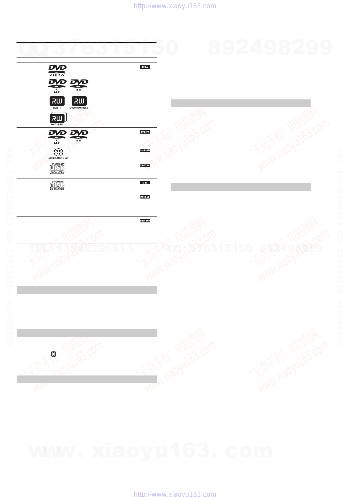
Playable Discs
Q
Q
Type Disc logo Characteristics Icon
DVD VIDEO • DVD VIDEO
VR (Video
Recording) mode
TEL 13942296513 QQ 376315150 892498299
Super Audio CD • Super Audio CD
VIDEO CD • VIDEO CD (Ver. 1.1 and 2.0 discs)
CD • Audio CD
DATA CD – • CD-R/CD-RW/CD-ROM in
DATA DVD – • DVD-ROM/DVD-R/DVD-RW/
1)
MP3 (MPEG1 Audio Layer 3) is a standard format defined by ISO/MPEG which compresses audiodata. MP3 files
TEL
must be in MPEG1 Audio Layer 3 format.
3
7
6
• DVD-R/DVD-RW in DVD
• DVD+R/DVD+RW in DVD
• DVD-R/DVD-RW in VR (Video
• Super VCD
• CD-R/CD-RW/CD-ROM in video
• CD-R/CD-RW in audio CD format
1
3
VIDEO format or video mode
VIDEO format
Recording) mode (except for
DVD-R DL)
CD format or Super VCD format
DATA CD format, containing MP3
1)
file
s
and JPEG image files2), and
DivX video files
conforming to ISO 9660
Level 2, or Joliet (extended format)
DVD+R/DVD+RW in DATA
DVD format, containing MP3
files
DivX video files
conforming to UDF (Universal
Disk Format)
3)4)5)
, and
1)
and JPEG image files2), and
3)4)5)
, and
13942296513
5
6)
Level 1/
1
5
0
2)
EG image files must conform to the DCF image file format.(DCF “Design rule for Camera File system”: Image
JP
standards for digital cameras regulated by Japan Electroni cs and Information Technology Industries Association
(JEITA).)
3)
Except for United Kingdom and North American models.
4)
DivX® is a video file compression technology, developed by DivX, Inc.
5)
DivX, DivX Certified, and associated logos are trademarks of DivX, Inc. and are used under license.
6)
A logical format of files and folders on CD-ROMs, defined by ISO (International Organization for
Standardization).
“DVD-RW,” “DVD+RW,” “DVD+R,”“DVD VIDEO,” and the “CD” logos are trademarks.
Example of discs that the system cannot play
The system cannot play the following discs:
• CD-ROM/CD-R/CD-RW other than those recorded in the formats listed
• CD-ROM recorded in PHOTO CD format
• Data part of CD-Extra
• CD Graphics disc
• DVD Audio
• DATA
DVD that does not contain MP3 files or JPEG image files, or DivX video files*
* Except for United Kingdom and North American models.
• DVD-RAM
Also, the system cannot play the following discs:
• A DVD VIDEO with a differen t region code
• A disc th at has a non-standard shape (e.g., card, heart)
• A disc with paper or stickers on it
• A disc that has the adhesive of cellophane tape or a sticker still left on it
Note about CD-R/CD-RW/DVD-R/DVD-RW/DVD+R/DVD+RW
In some cases, CD-R/CD-RW/DVD-R/DVD-RW/DVD+R/DVD+RW cannot be played on this system
due to the recording qualit y or physical condition of the disc, or the characteristics of the recording
device and authoring software.
The disc will not play if it has not been correctly finalized. For more information, refer to the operating
instructions for the recording device.
Note that some playback functions may not work with some DVD+RWs/DVD+Rs, even if they have
been correctly finalized. In this case, view the disc by normal playback. Also some DATA CDs/DATA
DVDs created in Packet Write format cannot be played.
Music discs encoded with copyright protection technologies
This product is designed to play back discs that conform to the Compact Disc (CD) standard.
Recently, various music di scs encoded with copyright protection technologies are marketed by some
record companies. Please be aware that among those discs, there are some that do not conform to the
CD standard and may not be playab le by this product.
Q
Q
Note on DualDiscs
A DualDisc is a two sided disc product which mates DVD recorded material on one side with digital
audio material on the other side. However, since the audio material side does not conform to the
Compact Disc (CD) standard , playback on this product is not guaranteed.
3
7
8
6
3
9
1
5
2
1
5
4
0
9
8
9
8
2
4
2
9
8
9
2
9
9
TEL 13942296513 QQ 376315150 892498299
9
About Multi Session CD
• This system can play a Multi Session CD when an MP3 file is contained in the first session. Any
subsequent MP3 files recorded in later sessions can also be pl ayed back.
• This system can play a Multi Session CD when a JPEG image file is contained in the first session.
Any subsequent JPEG image files recorded in later sessions can also be played back.
• If MP3 files and JPEG image files in music CD format or video CD format are recorded in the first
session, only the first session will be played back.
Region code
Your system has a regio n code printed on the rear of the unit and will only play a DVD labe led with
the same region code.
A DVD VIDEO labeled will also play on this system .
If you try to play any other DVD VIDEO, the message [Playback prohibited by area limitations.] will
appear on the TV screen. Dependingon the DVD VIDEO, no region code indication may be give ne ven
though playing the DVD VIDEO is prohibited by area restrictions.
Note about playback operations of a DVD or VIDEO CD
Some playback operations on a DVD or VIDEO CD may be intentionally set by software producers.
Since this system will play a DVD or VIDEO CD according to the disc contents the software producers
designed, some playback features may not be available. Be sure to read the operating instructions
supplied with the DVD or VIDEO CD.
w
ALL
w
w
.
xia
o
y
u
1
6
3
.
c
o
m
6
Q
HCD-HDX275/HDX277WC/HDX279W/HDX475/HDX576WF/HDX675
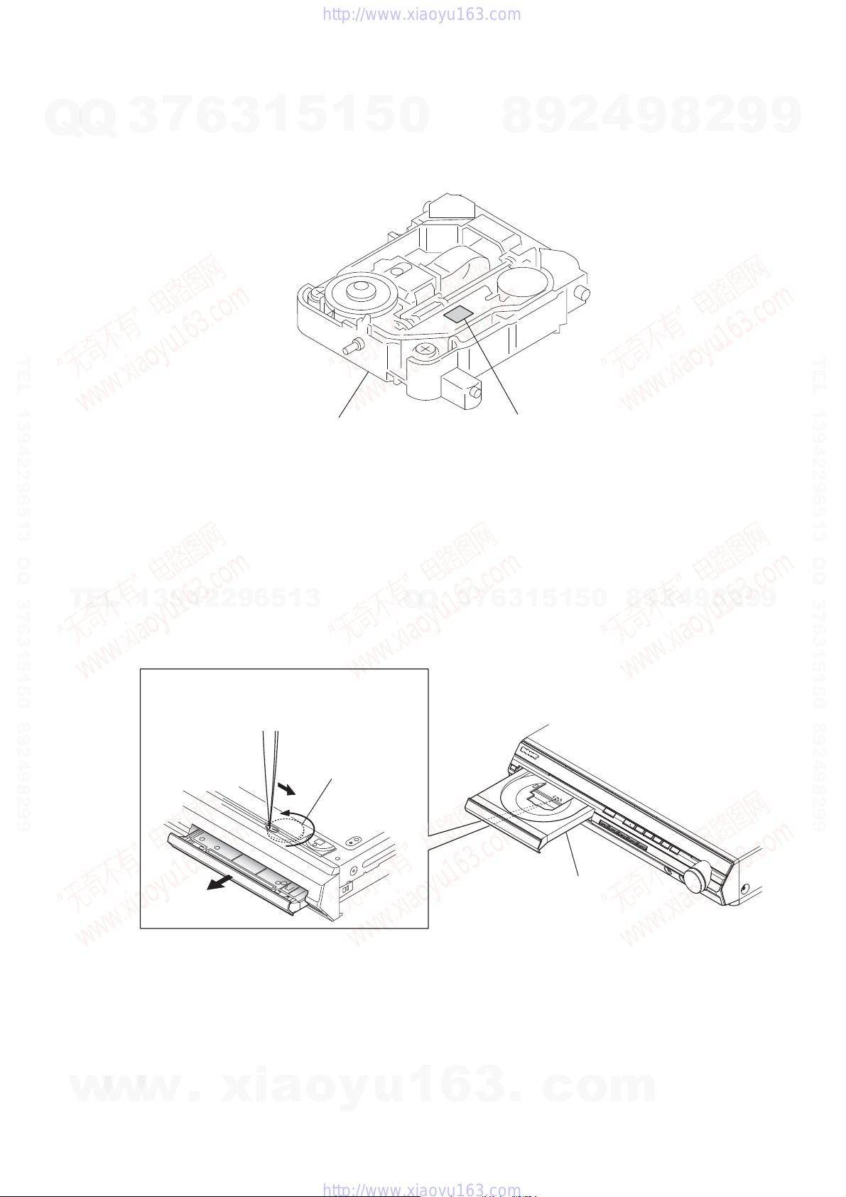
HOW TO IDENTIFY OPTICAL PICK-UP BLOCK
Q
3
7
6
1
5
3
Note: There are two kinds of OPTICAL PICK-UP BLOCK in this set.
When replacing the OPTICAL PICK-UP BLOCK, make sure which
OPTICAL PICK-UP BLOCK it is following the “How to Identify”
in the figure shown below.
1
5
0
8
9
2
4
9
8
2
9
9
TEL 13942296513 QQ 376315150 892498299
OPTICAL PICK-UP BLOCK
TEL
13942296513
HOW TO OPEN THE TRAY WHEN POWER SWITCH TURN OFF
Turn gear (BU1) from a hole at the bottom,
and pull out a tray.
Q
Printed of KHM-310CAB or KHM-313CAB.
7
3
Q
6
3
1
5
1
5
0
8
9
2
4
9
8
2
9
TEL 13942296513 QQ 376315150 892498299
9
w
w
w
.
xia
gear (BU1)
o
y
u
1
6
3
.
c
tray
o
m
7
HCD-HDX275/HDX277WC/HDX279W/HDX475/HDX576WF/HDX675
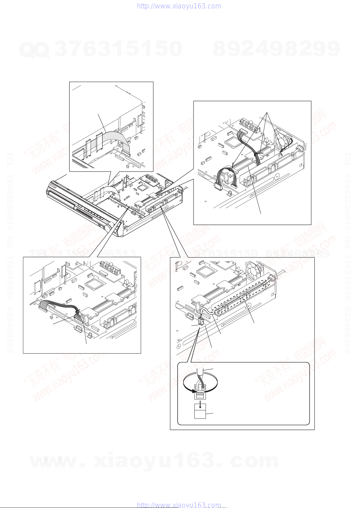
HARNESS SETTING
Q
Q
3
7
6
3
1
5
1
5
0
8
9
2
4
9
8
2
9
9
wire (flat type)
TEL 13942296513 QQ 376315150 892498299
TEL
13942296513
Q
Q
3
7
lead pin
Note 1: Check not touch the heatsink.
8
0
5
1
5
1
3
6
9
2
4
9
8
2
9
TEL 13942296513 QQ 376315150 892498299
9
8
lead pin
Note 2: Check not touch the heatsink.
w
w
w
.
xia
o
y
u
CN901
1
6
Note 4: Insert fully until
power cord
Note 5: Check not touch the chassis.
power cord
CN901
3
.
c
click the power cord.
Note 3: Twist the power cord
once counterclockwise
and connect to CN901.
o
m
HCD-HDX275/HDX277WC/HDX279W/HDX475/HDX576WF/HDX675
SECTION 2
GENERAL
This section is extracted
from instruction manual.
7
Q
Q
TEL 13942296513 QQ 376315150 892498299
3
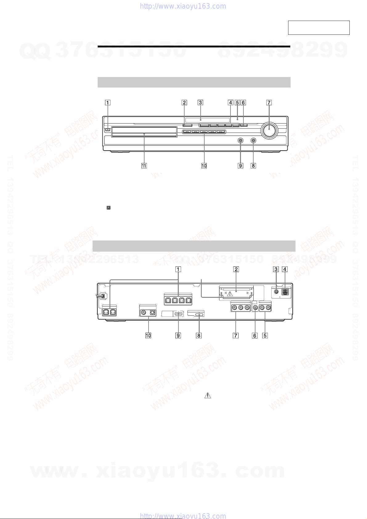
Index to Parts and Control
1
5
1
6
3
For more information, r ef e r to the pages indicat ed i n parentheses.
Front panel
" / (on/standby)
# " (open/close)
$ Front panel display
% Play operation buttons
& (remote sensor)
' FUNCTION
5
0
( VOLUME control
) PHONES jack
* AUDIO IN/A.CAL MIC jack
+ DISC 1-5buttons/indicators
, Disc tray
8
9
2
4
9
8
2
9
9
TEL 13942296513 QQ 376315150 892498299
TEL
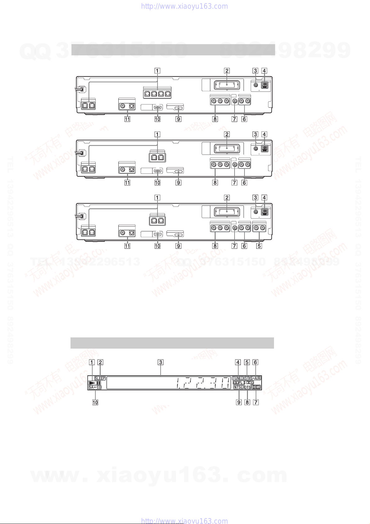
Rear panel
13942296513
HCD-HDX275/HDX475/HDX675
SPEAKER
CENTER SUBWOOFER
" SPEAKERjacks
# EZW -T1 00 slot
MCOAXIAL75Ω jack
$ F
% AM terminal
& TV/VIDEO (AUDIO IN R/L) jacks
' VIDEO OUT jack
TV/VIDEO
DIGITAL IN
COAXIAL OPTICAL
Q
Q
SPEAKER
FRONTR FRONT L SURR SUR L
HDMI OUT
0
5
1
5
1
3
6
7
3
Screws*
EZW-T100
COMPONENTVIDEO OUT
P
DMPORT
DC5V
0.7A MAX
( COMPONENT VIDEO OUT jacks
) DMPORT (DIGITAL MEDIA PORT) jack
* HDMI OUT j ack
+ TV/VIDEO (DIGITAL IN COAXIAL/
OPTICAL) jacks
* CAUTION
Please do not re movethe screw s before
installing the EZW-T100.
B/CBPR/CR
TV/VIDEO
VIDEO
OUT
AUDIO IN LRY
8
COAXIAL 75
9
9
2
8
9
4
2
9
ANTENNA
FM
AM
w
w
w
.
xia
o
y
u
1
6
3
.
c
o
m
9
HCD-HDX275/HDX277WC/HDX279W/HDX475/HDX576WF/HDX675
Rear panel
Q
Q
7
3
HCD-HDX277WC
6
3
1
5
1
5
0
8
9
2
4
9
8
2
9
9
SPEAKER
SPEAKER
CENTER SUBWOOFER
HCD-HDX279W
TV/VIDEO
DIGITAL IN
COAXIAL OPTICAL
TEL 13942296513 QQ 376315150 892498299
TV/VIDEO
DIGITAL IN
COAXIAL OPTICAL
TV
DIGITAL IN
COAXIAL OPTICAL
TEL
SPEAKER
CENTER SUBWOOFER
HCD-HDX576WF
SPEAKER
CENTER SUBWOOFER
" SPEAKERjacks
13942296513
# EZW-RT 10 slot
$ FM COAXIAL 75Ω jack
% AM terminal
& SAT/CABLE (AUDIO IN R/L) jacks
(HCD-HDX576WF only)
' TV/VIDEO (AUDIO IN R/L) jacks (HCD-
HDX277WC/HDX279W)
TV (AUDIO IN R/L) jacks (HCDHDX576WF)
FRONTR FRONT L SURR SUR L
HDMI OUT
SPEAKER
FRONTR FRONT L
HDMI OUT
SPEAKER
FRONTR FRONT L
HDMI OUT
DMPORT
DC5V
0.7A MAX
DMPORT
DC5V
0.7A MAX
DMPORT
DC5V
0.7A MAX
( VIDEO OUT jack
Q
Q
) COMPONENT VIDEO OUT jacks
* DMPO RT (DIGITAL MEDIA PORT) jack
+ HDMI OUT jack
, TV/VIDEO (DIGITAL IN COAXIAL/
EZW-RT10
COMPONENTVIDEO OUT
EZW-RT10
COMPONENTVIDEO OUT
EZW-RT10
COMPONENTVIDEO OUT
7
3
OPTICAL) jacks (HCD-HDX277WC/
HDX279W)
TV (DIGITAL IN COAXIAL/OPTICAL)
jacks (HCD-HDX576WF)
6
B/CBPR/CR
P
B/CBPR/CR
P
B/CBPR/CR
P
3
1
ANTENNA
FM
AM
COAXIAL 75
TV/VIDEO
VIDEO
OUT
AUDIO IN LRY
ANTENNA
FM
AM
COAXIAL 75
TV/VIDEO
VIDEO
OUT
AUDIO IN LRY
ANTENNA
FM
AM
COAXIAL 75
TV
AUDIO IN LRY
1
SAT/CABLE
5
AUDIO INRL
0
8
9
2
4
9
8
2
9
9
VIDEO
OUT
5
TEL 13942296513 QQ 376315150 892498299
10
w
w
Front panel display
About the indications in the front panel display
" Playing status
# Flashes when the sleep timer is set.
$ Displays system’s status such as
chapter, title, or track number, time
information, radio frequency, playing
status, decoding mode, etc.
% Lights up when a station is received.
(Radio only)
& Stereo/Mo n au ral effect (Radio only)
' Lights up when the S-AIR transmitter
w
(not supplied) is inserted in the unit
.
xia
and the system transmits the sound.
o
y
( Lights up when the HDMI OUT jack is
correctly connected to HDCP (Highbandwidth Digital Content Protection)
compliant device with HDMI or DVI
(Digital Visual Interface) input.
) Current surround format (Except for
JPEG image file)
* Lights up when the color system is set
toNTSC.(Asian,Australian, and Middle
Eastern models only)
+ Lights up when Super Audio CD/CD is
u
1
6
3
.
loaded.
c
o
m
HCD-HDX275/HDX277WC/HDX279W/HDX475/HDX576WF/HDX675
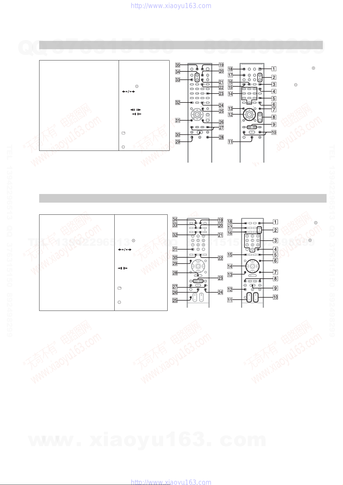
Remote control
7
Q
Q
3
HCD-HDX275/HDX277WC/HDX279W/HDX475/HDX576WF
A–O P–Z
ANGLE
AUDIO RI
CLEAR FT
D.TUNING XT
DISC SKIP
FE
DISPLAY XB
DVD MENU XH
DVD TOP MENU RE
DYNAMIC BASS
1)
ENTER
XG
FUNCTION +/–
MENU XH
MUTING
NIGHT XE
ONE-TOUCH PLAY FH
TEL 13942296513 QQ 376315150 892498299
6
ALPHABETICAL ORDER BUTTON DESCRIPTIONS
PICTURE NAVIRH
PRESET +/– XK
PROG +/–
S-AIR MODE
SLEEP RK
SOUND MODE
SUBTITLE XT
SYSTEM MENU XG
THEATER/THEATRE
TOOLS XI
TUNING +/–
TV XM
TV CH +/–
TV INPUT X
TV VOL +/– FG
VOLUME +/–
3
2)
XK
3)
5)
XK
1
4)
RL
5
1
Number buttons RG
</ (on/standby)
TV </ (on/standby) RM
$/9/Y/D/
/ XK
N/.
STEP /
SLOW /
)(play) F
Y (stop) XL
9 (pause) RB
0 RETURN FB
-/--
DISPLAY
2)
5)
FT
FT
RT
REPLAY/ADVANCE
6)
XI
5
0
8
9
2
4
9
2
8
1)
The ENTER button has the
same functionasthe
button. When you operate
theTV,theENTERbutton is
used for selecting a channel,
and the buttonisusedfor
selecting menuitems
2)
Except for North American
models.
3)
HCD-HDX275/HDX475
only.
4)
The button name differs
dependingonthearea.
5)
North American models
only.
6)
This buttonisavailablefor
the “DVD” or “DMPORT”
function.Dependingonthe
DIGITALMEDIA PORT
adapter, this buttonmaynot
work.
9
9
.
TEL 13942296513 QQ 376315150 892498299
Remote control
HCD-HDX675
ANGLE
AUDIO F
CC F
CLEAR FB
TEL
D.TUNING XT
DISC SKIP RI
DISPLAY FT
DVD MENU
DVD TOP MENU XM
DYNAMIC BASS XB
ENTER*
FAVORITES RH
FUNCTION +/–
GUIDE XM
INPUT
Z–ML–A
MENU XE
MUTING XH
NIGHT X
13942296513
ONE-TOUCH PLAY FG
PICTURE NAVIRH
PRESET +/–
S-AIR MODE RK
SLEEP FE
SOUND MODE +/–
SUBTITLE XT
SYSTEM MENU
THEATER RL
TOOLS
TV RT
TV CH +/–
TV VOL +/– RB
TUNING +/– XK
VOLUME +/– RB
Number buttons
</ (on/standby)
TV </ (on/standby) RM
$/9/Y/D/ RG
XE
/
N/. XK
/ XK
)(play)
Y (s
top) XG
9 (pause) XI
DISPLAY** XL
0 RETURN RE
FB
SNOITPIRCSEDNOTTUBREDROLACITEBAHPLA
REPLAY/ADVANCE
Q
Q
3
7
6
3
1
5
1
5
0
8
9
* The ENTER button has the
same functionasthe
button. When you operate
the TV, the ENTER button
is usedforselecting a
channel,and the button
is used for selecting menu
8
9
4
2
items.
** This buttonisavailablefor
the “DVD” or “DMPORT”
function. Depending on the
DIGITAL MEDIA PORT
adapter, this button maynot
work.
2
9
9
w
w
w
.
xia
o
y
u
1
6
3
.
c
o
m
11
HCD-HDX275/HDX277WC/HDX279W/HDX475/HDX576WF/HDX675
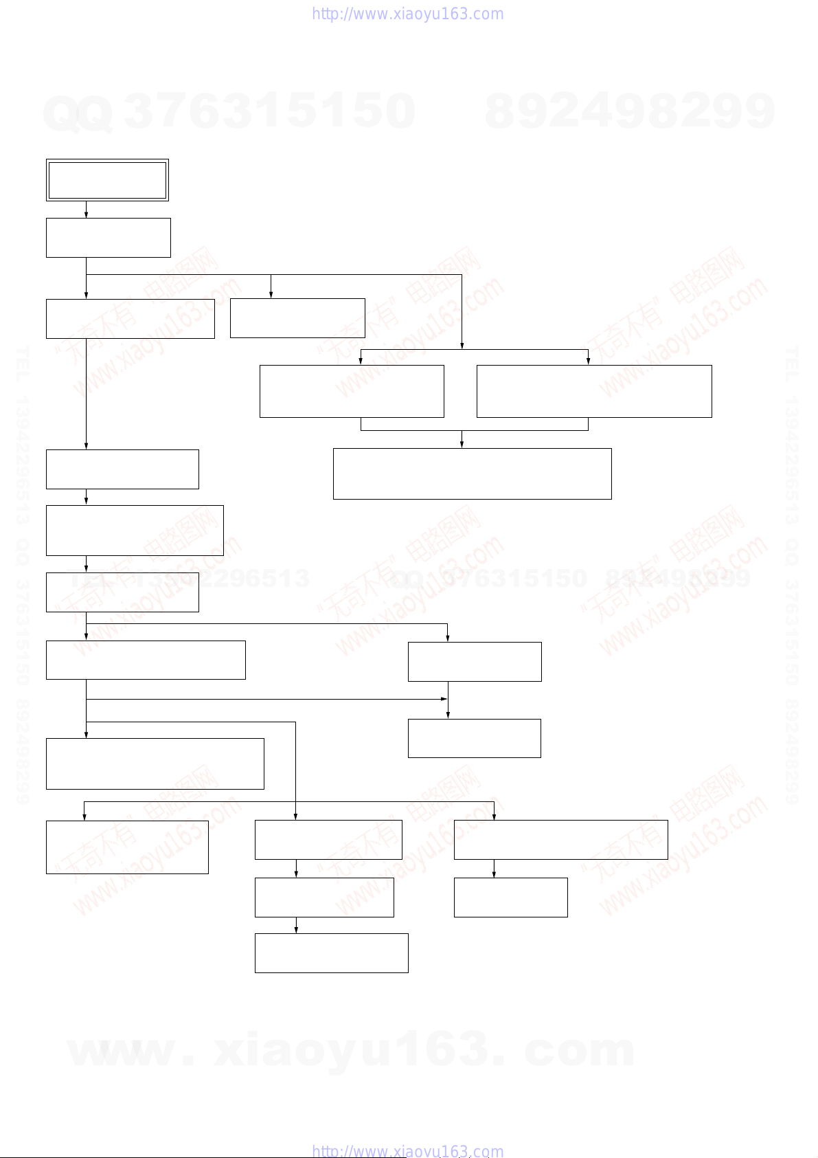
SECTION 3
DISASSEMBLY
• This set can be disassembled in the order shown below.
7
Q
Q
3-1. DISASSEMBLY FLOW
3-2. CASE (DCR)
(Page 13)
3
SET
6
3
1
5
1
5
0
8
9
2
4
9
8
2
9
9
3-3. FRONT PANEL BLOCK
(Page 13)
TEL 13942296513 QQ 376315150 892498299
3-8. COVER (CDM-DCR)
(Page 16)
3-9. DVD MECHANISM DECK
(CDM81C-DVBU101)
(Page 16)
TEL
3-10. TRAY (MAIN) ASSY
(Page 17)
3-12. OPTICAL PICK-UP SECTION
(Page 18)
13942296513
3-4. POWER BOARD
(Page 14)
3-5. BACK PANEL BLOCK
(HDX275/HDX475/HDX675)
(Page 14)
3-7. SPEAKER BOARD, SERIPARA BOARD AND
MAIN BOARD
(Page 15)
7
3
Q
Q
3-11. MOTOR BOARD
(Page 17)
3-6. BACK PANEL BLOCK
(HDX277WC/HDX279W/HDX576WF)
(Page 15)
4
2
9
8
0
5
1
5
1
3
6
9
8
2
9
TEL 13942296513 QQ 376315150 892498299
9
3-13. OPTICAL PICK-UP BLOCK
(KHM-310CAB OR KHM-313CAB)
(Page 18)
3-14. GEAR (SUB TRAY 1)/
GEAR (SUB TRAY 2)
(Page 19)
w
w
w
12
.
3-16. STOCKER BLOCK
(Page 20)
3-17. CAM (STOCKER)
(Page 20)
3-18. GEAR (STOCKER 3)
(Page 21)
xia
o
y
u
3-15. LEVER (MODE)
(Page 19)
3-19. ROTARY ENCODER (MD) (S771)
(Page 21)
3-20 . GEAR (BU1)
(Page 22)
1
6
3
.
c
o
m
Q
HCD-HDX275/HDX277WC/HDX279W/HDX475/HDX576WF/HDX675
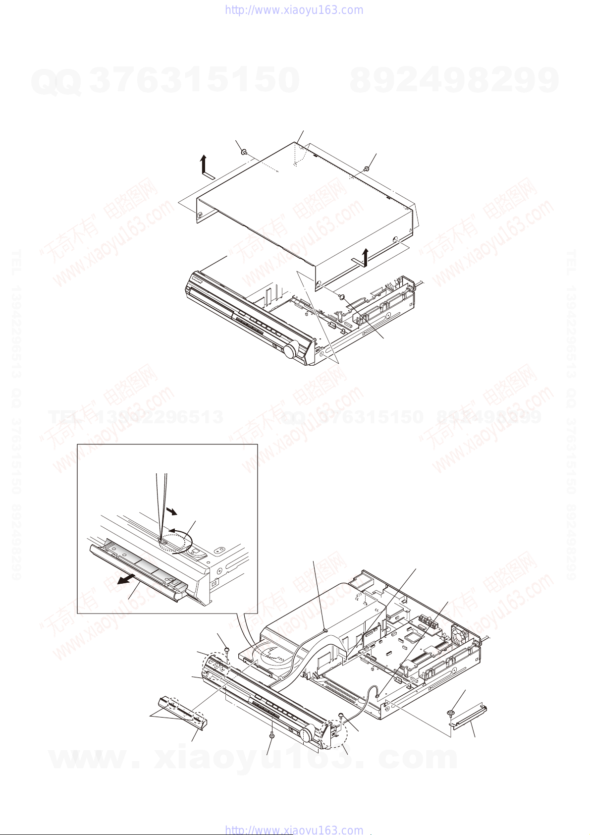
Note: Follow the disassembly procedure in the numerical order given.
7
Q
3
3-2. CASE (DCR)
6
3
1
5
two screws
(case 3 TP2)
1
5
0
case (DCR)
8
2
9
five screws
(BV3)
4
9
8
2
9
9
TEL 13942296513 QQ 376315150 892498299
TEL
13942296513
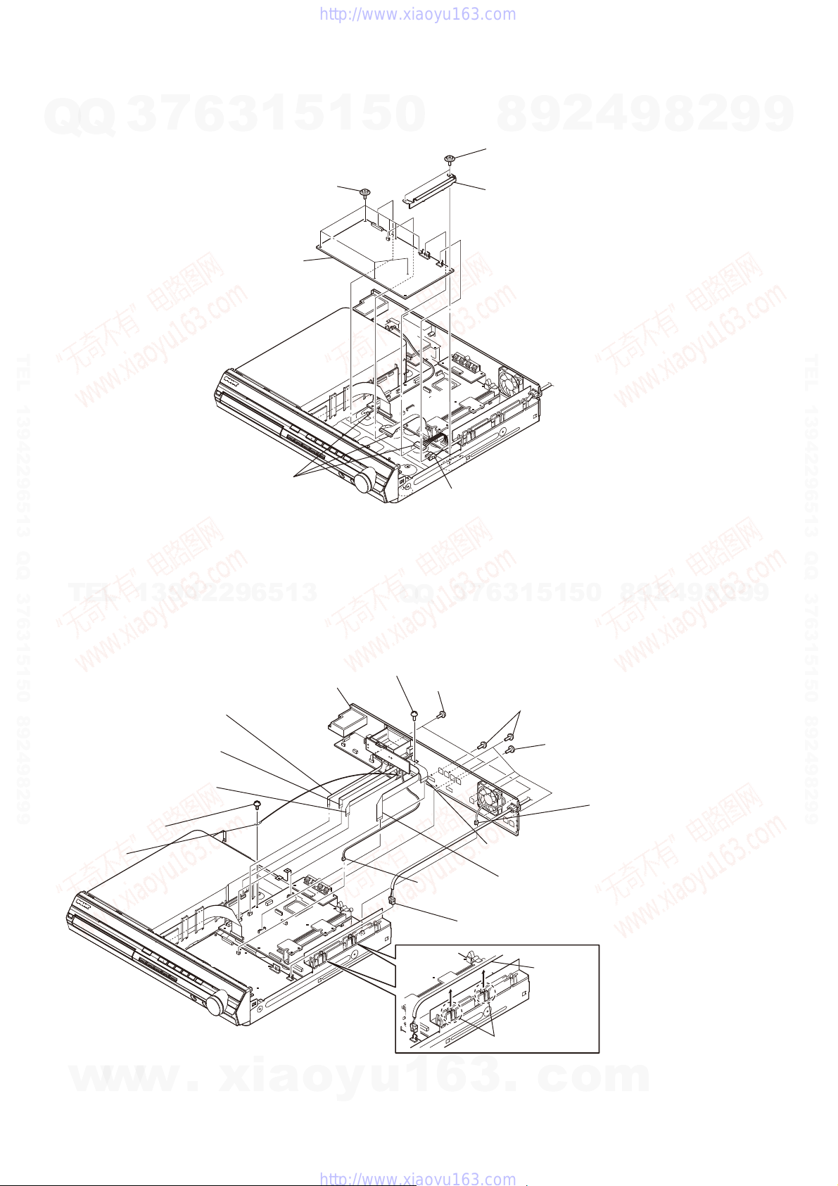
3-3. FRONT PANEL BLOCK
Turn gear (BU1) from a hole
at the bottom, and pull out a tray.
gear (BU1)
Q
Q
3
7
6
3
two screws
(case 3 TP2)
1
5
1
5
0
8
9
2
4
9
8
2
9
TEL 13942296513 QQ 376315150 892498299
9
w
w
Open the tray.
RE
two claws
w
screw (BV3)
R
claw
RT
front panel block
loading panel (DCR)
.
xia
connector
(CN412)
four screws
y
RB
u
(BV3)
1
6
3
o
RT
R
claw
.
screw (BV3)
c
o
wire (flat type) (21 core)
(CN501)
connector
(CN3001)
two screws
(PWH3 × 8)
shield plate (HP)
m
13
HCD-HDX275/HDX277WC/HDX279W/HDX475/HDX576WF/HDX675
3-4. POWER BOARD
Q
Q
3
7
6
1
3
seven screws
(PWH3 × 8)
POWER board
5
1
5
0
9
8
two screws
(PWH3 × 8)
shield plate (HP)
2
4
9
8
2
9
9
TEL 13942296513 QQ 376315150 892498299
three connectors
(CN904, CN906, CN908)
TEL
3-5. BACK PANEL BLOCK (HDX275/HDX475/HDX675)
(CN606)
13942296513
wire (flat type) (5 core)
(CN702)
wire (flat type) (9 core)
back panel block
RI
screw (BV3)
RB
Q
Q
power cord connector
(CN901)
7
3
three screws
RT
(BV3)
6
1
3
RE
(BV3)
5
1
5
five screws
screw
RG
(B3 × 6)
0
8
9
2
4
9
8
2
9
TEL 13942296513 QQ 376315150 892498299
9
14
wire (flat type) (7 core)
(CN653)
screw (BV3)
terminal
R
w
w
w
.
xia
connector
(CN908)
(CN901)
o
y
u
1
6
3
wire (flat type) (17 core)
(CN4302)
wire (flat type) (17 core)
(CN651)
power cord connector
power cord
four claws
RH
.
c
o
fan motor connector
(CN3000)
m
Q
HCD-HDX275/HDX277WC/HDX279W/HDX475/HDX576WF/HDX675
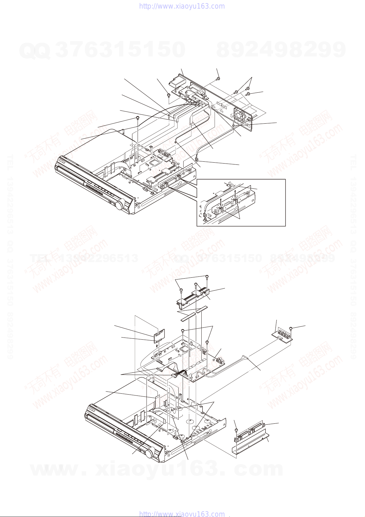
3-6. BACK PANEL BLOCK (HDX277WC/HDX279W/HDX576WF)
Q
7
3
(CN606)
(CN653)
6
wire (flat type) (5 core)
(CN702)
wire (flat type) (9 core)
wire (flat type) (7 core)
screw (BV3)
3
1
5
1
5
RI
screw (BV3)
RB
0
back panel block
9
8
three screws
RT
(BV3)
2
RE
(BV3)
4
9
five screws
screw
RG
(B3 × 6)
2
8
fan motor connector
(CN3000)
9
9
terminal
R
TEL 13942296513 QQ 376315150 892498299
connector
(CN908)
TEL
13942296513
3-7. SPEAKER BOARD, SERIPARA BOARD AND MAIN BOARD
two screws
RG
(BV3)
two radiation sheets
RK
SERIPARA board
connector
(CN650)
Q
Q
7
3
RH
(BVTP3 × 12)
wire (flat type) (17 core)
(CN4302)
wire (flat type) (17 core)
(CN651)
power cord connector
(CN901)
four claws
RH
5
1
5
1
3
6
heatsink (AMP)
RI
screw
seven screws
RL
(BV3)
MAIN board
RM
power cord
8
0
9
4
2
9
SPEAKER board
9
2
8
two screws
(BV3)
TEL 13942296513 QQ 376315150 892498299
9
w
w
two connectors
(CN904, CN906)
wire (flat type) (21 core)
(CN651)
wire (flat type) (21 core)
(CN501)
w
.
xia
wire (flat type) (24 core)
o
y
(CN1101)
u
1
6
3
two connectors
R
(CN1201, CN3001)
three screws
RB
(BV3)
.
c
o
connector
(CN114: HDX275/HDX277WC/
HDX475/HDX675,
CN115: HDX279W/HDX576WF)
plate insulated (POW)
RT
plate shield (POW-DCR)
RE
m
15
HCD-HDX275/HDX277WC/HDX279W/HDX475/HDX576WF/HDX675
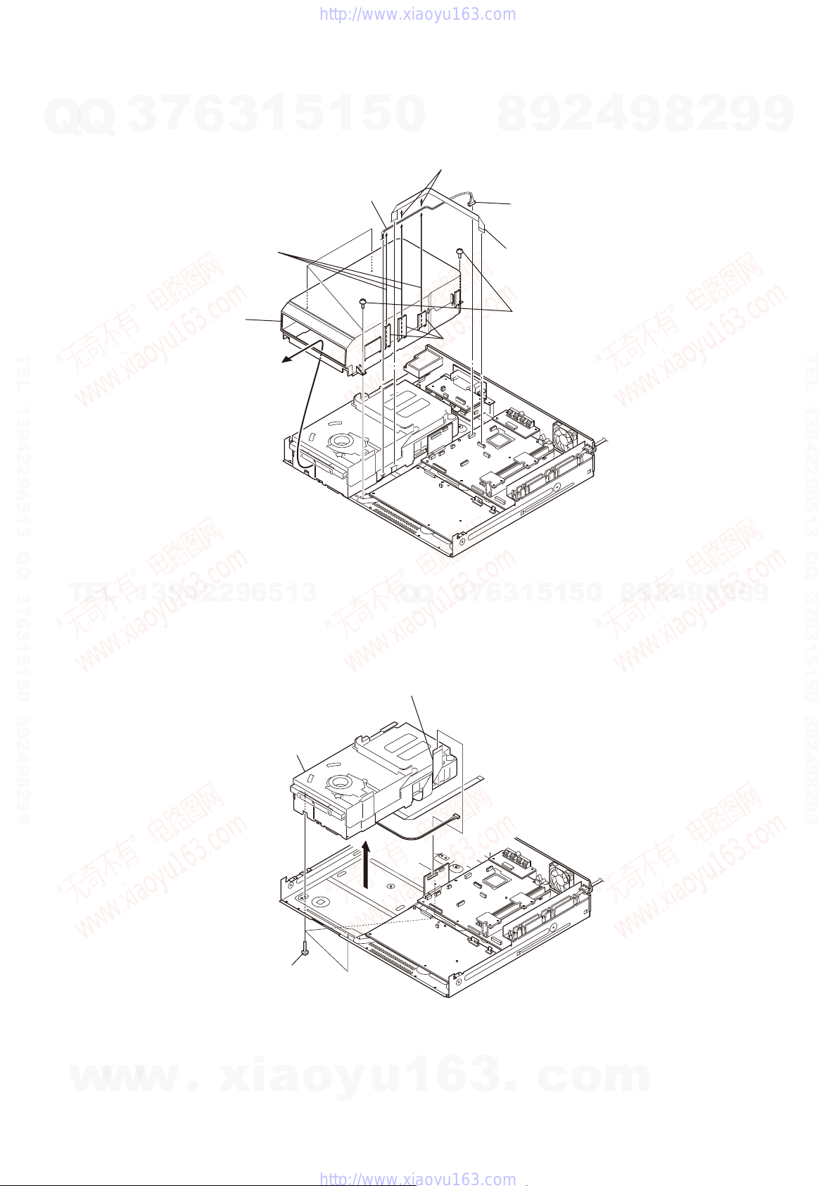
3-8. COVER (CDM-DCR)
7
Q
Q
TEL 13942296513 QQ 376315150 892498299
3
cover (CDM-DCR)
6
Remove lead wire
from 3 ditches.
3
1
5
1
lead wire
5
0
9
8
Remove wire (flat type) (24 core)
from 2 ditches.
connector
(CN1201)
wire (flat type) (24 core)
(CN1101)
four screws
ditch
(BV3)
2
4
9
8
2
9
9
TEL 13942296513 QQ 376315150 892498299
TEL
3-9. DVD MECHANISM DECK (CDM81C-DVBU101)
13942296513
DVD mechanism deck
(CDM81C-DVBU101)
three screws
(BVTP3 × 10)
6
7
3
Q
Q
wire (flat type) (21 core)
(CN651)
3
1
5
1
5
0
8
9
2
4
9
8
2
9
9
16
w
w
w
.
xia
o
y
u
1
6
3
.
c
o
m
HCD-HDX275/HDX277WC/HDX279W/HDX475/HDX576WF/HDX675
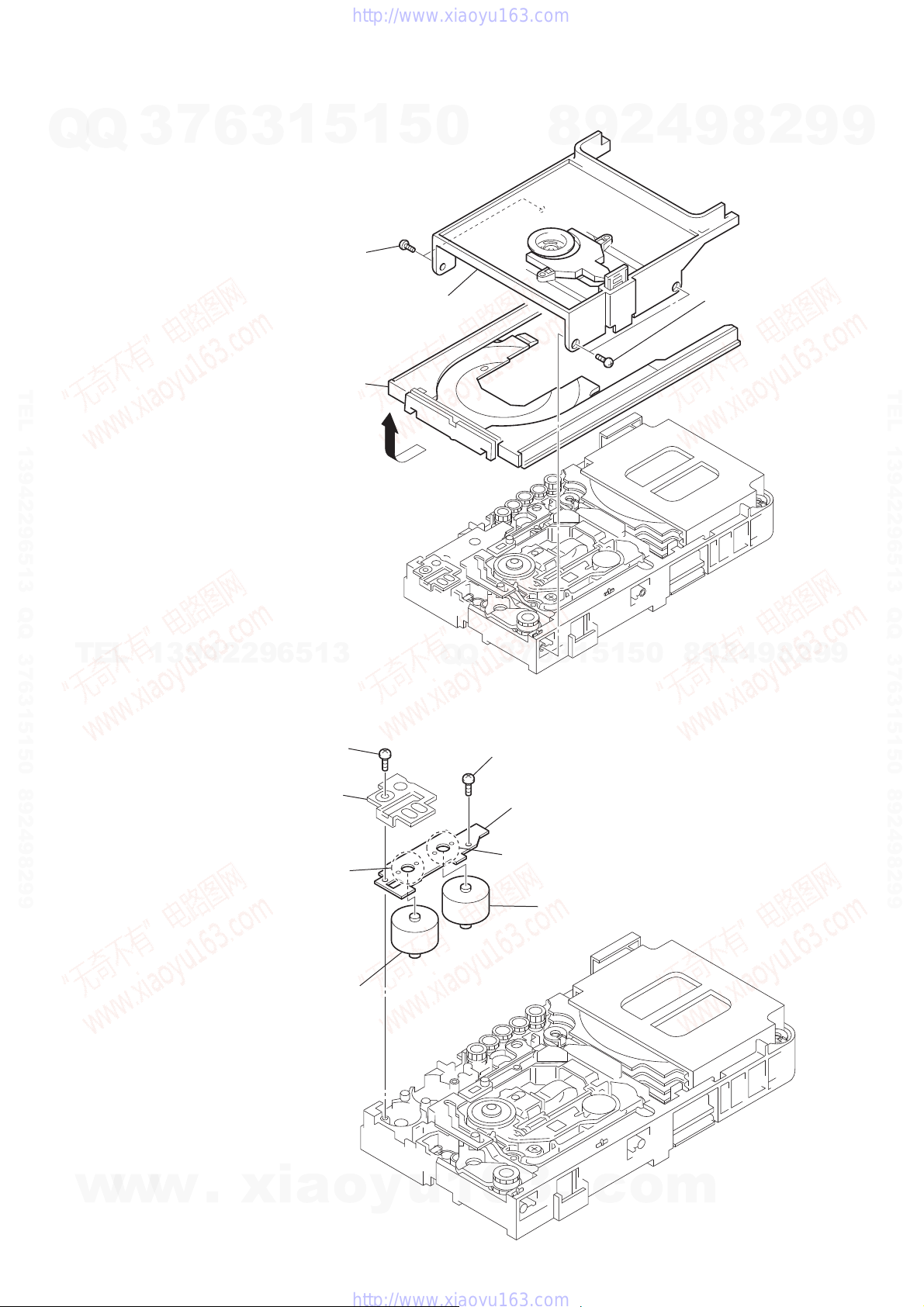
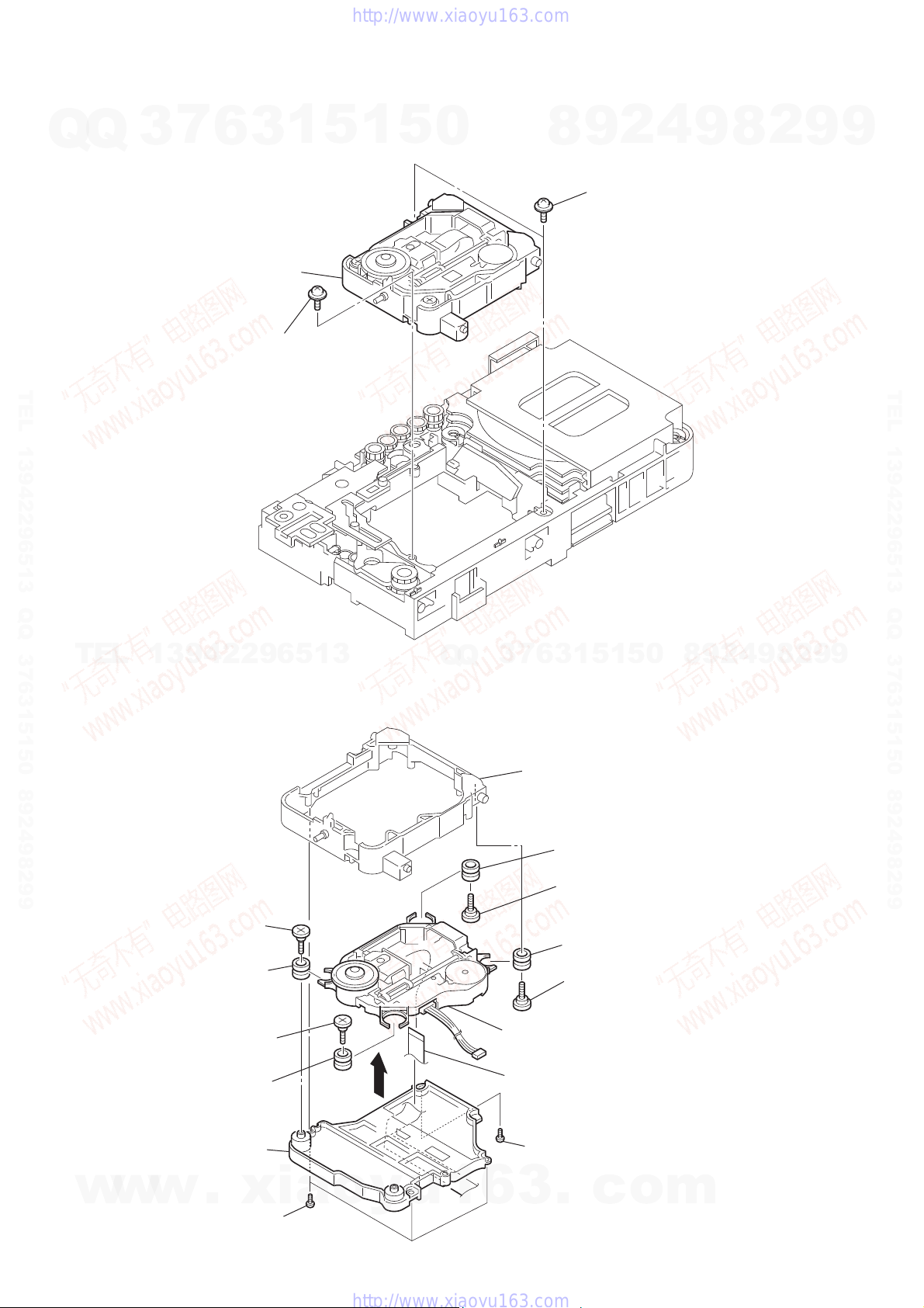
3-10. TRAY (MAIN) ASSY
7
Q
Q
TEL 13942296513 QQ 376315150 892498299
3
6
tray (main) assy
Remove the tray (main) assy
in the direction of the arrow.
3
1
two screws
(BTTP M2.6)
5
1
5
bracket (top)
0
8
9
2
4
9
2
8
two screws
(BTTP M2.6)
9
9
TEL 13942296513 QQ 376315150 892498299
TEL
13942296513
3-11. MOTOR BOARD
motor (81) assy (BU U/D motor)
screw
(BTTP M2.6)
bracket
Remove two solders.
(M762 )
Q
Q
screw
(BTTP M2.6)
5
1
5
1
3
6
7
3
MOTOR board
Remove two solders.
motor (81) assy (LD/ST motor)
(M761)
0
8
9
2
4
9
8
2
9
9
w
w
w
.
xia
o
y
u
1
6
3
.
c
o
m
17
HCD-HDX275/HDX277WC/HDX279W/HDX475/HDX576WF/HDX675
3-12. OPTICAL PICK-UP SECTION
Q
Q
7
3
optical pick-up section
6
floating screw
(PTPWH M2.6)
3
1
5
1
5
0
9
8
two floating screws
(PTPWH M2.6)
2
4
9
8
2
9
9
TEL 13942296513 QQ 376315150 892498299
TEL
3-13. OPTICAL PICK-UP BLOCK (KHM-310CAB OR KHM-313CAB)
13942296513
Q
Q
7
3
holder (310)
6
3
1
5
1
5
0
8
9
2
4
9
8
2
9
TEL 13942296513 QQ 376315150 892498299
9
18
w
w
insulator screw
R insulator
insulator screw
insulator
base (310)
w
.
three screws
(BTP2.6 × 8)
xia
o
y
u
1
R insulator
insulator screw
R insulator
insulator screw
RT optical pick-up block
(KHM-310CAB or KHM-313CAB)
RB wire (flat type) (24 core)
screw
(BTP2.6 × 8)
6
3
.
c
o
m
Q
HCD-HDX275/HDX277WC/HDX279W/HDX475/HDX576WF/HDX675
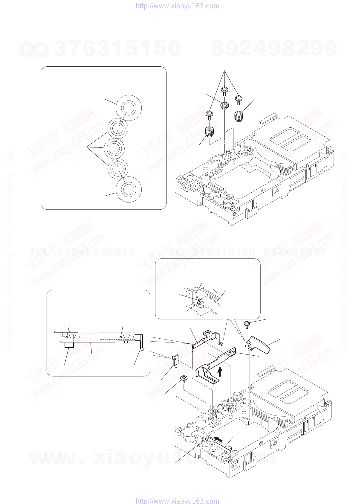
3-14. GEAR (SUB TRAY 1)/GEAR (SUB TRAY 2)
7
Q
3
PRECAUTION DURING GEAR (SUB TRAY 1/2) INSTALLATION
Align the marks of the gears as shown in the illustration.
6
gear (sub tray 2)
3
1
5
1
5
0
three gears
(sub tray 1)
2
9
8
five screws
(PTPWH2.6 × 8)
4
gear (sub tray 2)
9
8
2
9
9
TEL 13942296513 QQ 376315150 892498299
TEL
gear (sub tray 1)
gear (sub tray 2)
3-15. LEVER (MODE)
13942296513
Before re-assembling, align the lever (release)
and the lever (sub tray) with the lever (mode)
as shown in the illustration.
dowel dowel
gear (sub tray 2)
7
3
Q
Q
When re-assembling, insert the lever (sub tray)
between the bosses of the shutter (tray).
shutter (tray)
boss
boss
lever (sub tray)
6
3
5
1
5
1
lever (sub tray)
0
4
2
9
8
screw
(PWH2.6 × 8)
9
8
2
9
TEL 13942296513 QQ 376315150 892498299
9
w
w
lever (release)
w
.
lever (mode)
xia
lever (sub tray)
lever (release)
floating screw
(PTPWH M2.6)
o
y
u
1
Before re-assembling, slide the cam (BU)
in the direction of the arrow.
6
3
.
cam (BU)
c
o
shutter (tray)
lever (mode)
m
19
HCD-HDX275/HDX277WC/HDX279W/HDX475/HDX576WF/HDX675
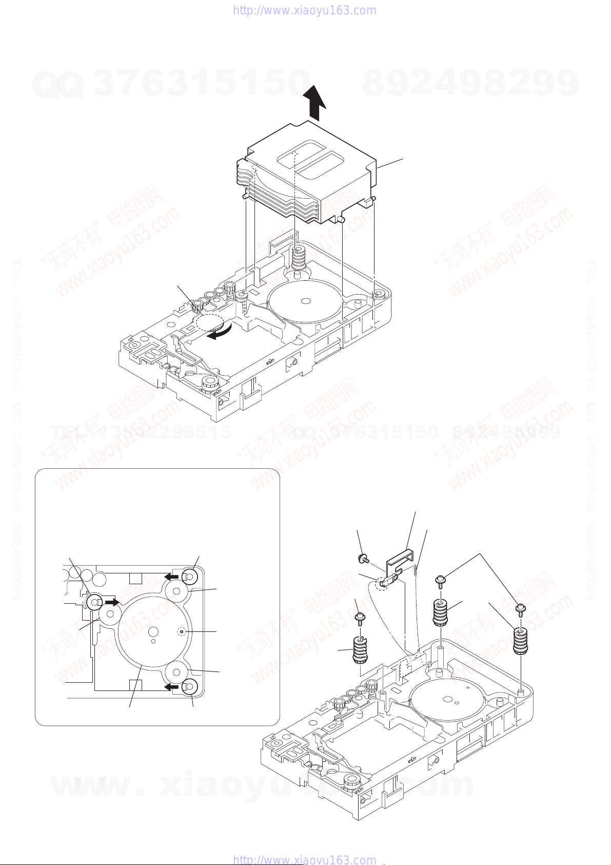
3-16. STOCKER BLOCK
Q
Q
3
7
6
3
1
5
1
5
0
8
2
9
stocker block
4
9
8
2
9
9
TEL 13942296513 QQ 376315150 892498299
Rotate the gear (SS3) in the
direction of the arrow.
TEL
3-17. CAM (STOCKER)
PRECAUTION DURING CAM (STOCKER) INSTALLATION
Before installing the cams (stocker), fix the gear (stocker 3) in
the manner so that the hole of the gear (stocker 3) should be
aligned with the hole of the chassis located beneath
the gear (stocker 3). Be sure to install the cams (stocker) in
such a way that the grooves of the cams (stocker) face
the direction of the arrows.
cam (stocker)
13942296513
cam (stocker)
Q
Q
floating screw
(PTPWH M2.6)
3
7
6
3
1
5
1
2
9
8
0
5
lever (SW)
tension spring (SW)
two screws
(PWH2.6 × 8)
4
9
8
2
9
TEL 13942296513 QQ 376315150 892498299
9
gear
(stocker 2)
20
w
w
gear (stocker 3)
w
.
cam (stocker)
xia
gear
(stocker 2)
hole
gear
(stocker 2)
o
y
screw
(PWH2.6 × 8)
cam
(stocker)
u
1
hook
6
3
.
c
o
two cams
(stocker)
m
Q
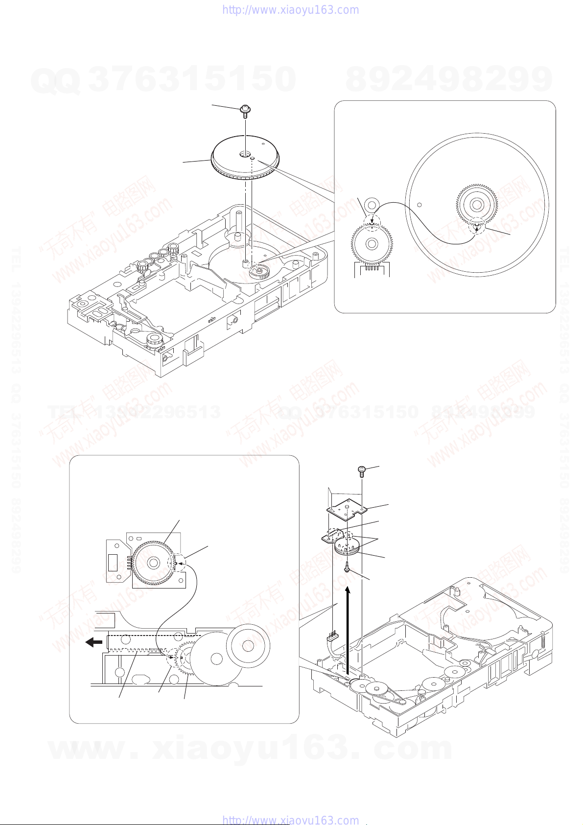
3-18. GEAR (STOCKER 3)
7
Q
3
6
step tapping screw
(PTPWH M2.6)
gear (stocker 3)
HCD-HDX275/HDX277WC/HDX279W/HDX475/HDX576WF/HDX675
1
5
1
3
5
0
4
2
9
8
PRECAUTION DURING GEAR (STOCKER 3) INSTALLATION
Be sure to align the rib of the gear (stocker 3) with the groove
of the rotary encoder.
groove
9
8
2
9
9
TEL 13942296513 QQ 376315150 892498299
TEL
13942296513
3-19. ROTARY ENCODER (MD) (S771)
PRECAUTION DURING ROTARY ENCODER (MD) INSTALLATION
Slide the cam (BU) in the direction of the arrow so that the mark
of the gear (BU1) can be seen. Engage the gears while aligning
the mark of the gear (BU1) with the protruding part of the
rotary encoder.
rotary encoder (MD)
Q
Q
3
7
rotary encoder
(ST U/D encoder)
1
5
1
3
6
(BTTP M2.6)
gear (stocker 3)
(reverse-side)
4
2
9
8
0
5
three screws
bracket (encoder)
Remove the five solders.
9
8
2
rib
9
TEL 13942296513 QQ 376315150 892498299
9
w
w
cam (BU)
w
mark
.
xia
gear (BU1)
protruding part
o
y
u
1
6
3
two claws
rotary encoder (MD)
(S771)
step tapping screw
(2 × 6 PWH)
– CD mechanism deck bottom view –
.
c
o
m
21
HCD-HDX275/HDX277WC/HDX279W/HDX475/HDX576WF/HDX675
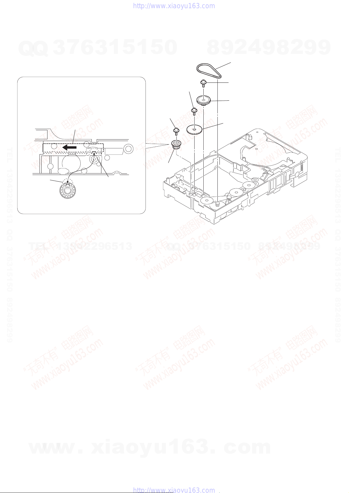
3-20. GEAR (BU1)
7
Q
Q
PRECAUTION DURING GEAR (BU2) INSTALLATION
3
6
3
1
5
1
5
0
8
2
9
belt (sub tray)
4
9
8
2
9
9
Before re-assembling, slide the cam (BU) in the direction of
the arrow.
Assemble the gear (BU2) in such a manner that the groove
of the cam (BU) is aligned with the rib of the gear (BU2).
cam (BU)
TEL 13942296513 QQ 376315150 892498299
rib
TEL
gear (BU2)
13942296513
groove
screw
(PWH2.6 × 8)
screw
(PWH2.6 × 8)
gear (BU2)
Q
Q
– CD mechanism deck bottom view –
7
3
6
3
1
screw
(PWH2.6 × 8)
pulley (BU)
gear (BU1)
0
5
1
5
8
9
2
4
9
8
2
9
TEL 13942296513 QQ 376315150 892498299
9
22
w
w
w
.
xia
o
y
u
1
6
3
.
c
o
m
HCD-HDX275/HDX277WC/HDX279W/HDX475/HDX576WF/HDX675
SECTION 4
TEST MODE
Ver. 1.1
Note: Incorrect operations may be performed if the test mode is not
entered properly. In this case, press the [?/1] button to turn the
7
Q
Q
TEL 13942296513 QQ 376315150 892498299
TEL
3
power off, and retry to enter the test mode.
COLD RESET
The cold reset clears all data including preset data stored in the
RAM to initial conditions. Execute this mode when returning the
set to the customers.
Procedure:
1. Press the [?/1] button to turn the power on.
2. Press three buttons [s], [A] and [?/1] simultaneously.
3. When this button is operated, display as “COLD RESET” for
a while and all of the settings are reset.
PANEL TEST MODE
This mode is used to check the software version, FL, LED and
KEY.
1. Display Test Mode
Procedure:
1. Press the [?/1] button to turn the power on.
2. Press three buttons [S], [l] and [A] simultaneously.
3. When the display test mode is activated, all segments are
turned on.
4. To exit from this mode, press three buttons [
simultaneously.
2. Version Test Mode
Procedure:
1. When the display test mode is activated, press the [l] button
and “DCR2” is displayed, the version test mode is activated.
2. Whenever the [
order of “DCR2” (model name) → “NA” (destination) → MC
→ SYS → UI → DVD → CDMA → CDMB → ST → TA →
13942296513
DSP → TM → CLA → CEC → SAIR → “DCR2” (model
name).
Note: Model name/destination is different according to model.
3. Press the [L] button and the date of the software production
is displayed.
4. Press the [L] button again and the version is displayed.
5. To exit from this mode, press three buttons [S], [l] and [A]
simultaneously.
3. Key Test Mode
Procedure:
1. When the display test mode is activated, press the [
to select the key test mode.
2. To enter the KEY test mode, the fl uorescent indicator displays
“K0 V0”. Each time an another button is pressed, “KEY” value
increases. However, once a button is pressed, it is no longer
taken into account. When all keys are pressed correctly, “K13
V0” is displayed.
3. When the [VOLUME] dial is turned in the direction of (+),
“V0” is changed to “V1”, then ... “V9”.
When the [VOLUME] dial is turned in the direction of (–),
“V0” is changed to “V9”, then ... “V1”.
4. To exit from this mode, press three buttons [S], [l] and [A]
simultaneously.
6
l
1
5
1
3
] button is pressed, the display changes in
5
0
], [l] and [A]
S
Q
] button,
H
Q
Releasing Procedure:
1. Press the [
seconds again.
2. The message “UNLOCKED” is displayed and the tray is unlocked.
Note: When “LOCKED” is displayed, the tray lock is not released by
DVD SHIP MODE
Use this mode when returning the set to the customer after repair.
Procedure:
1. Press the [
2. Press the [FUNCTION] button to set the function “DVD”.
3. Remove all discs, and then press two buttons [
simultaneously.
4. After a message “MECHA LOCK” h “UNPLAG” is displayed on the fl uorescent indicator tube, pull out the AC plug.
5. To exit from this mode, press the [
on.
AM STEP CHANGE
A step of AM channels can be changed over between 9 kHz and
10 kHz.
Procedure:
1. Press the [?/1] button to turn the set ON.
2. Press the [FUNCTION] button to set the function “TUNER
AM”.
3. Press the [?/1] button to turn the set OFF.
4. Press two buttons [L] and [?/1] simultaneously, and the display of fl uorescent indicator tube changes to “AM 9k STEP” or
“AM 10k STEP”, and thus the channel step is changed over.
PRODUCT OUT
7
3
This mode moves the optical pick-up to the position durable to vibration and clears all data including preset data stored in the RAM
to initial conditions. Use this mode when returning the set to the
customer after repair.
Procedure:
1. Press the [
2. Press the [FUNCTION] button to set the function “DVD”.
3. Remove all discs, and then press three buttons [
[?/1] simultaneously.
4. After the “STANDBY” blinking display fi nishes, the message
“MECHA LOCK” h “UNPLAG” is displayed on the fl uo-
rescent indicator tube disconnect the AC power plug, then the
ship mode is set.
] button and the [A] button simultaneously for fi ve
s
9
8
turning power on/off with the [?/1] button.
] button to turn the set on.
?/1
1
5
1
3
6
] button to turn the power on.
?/1
2
5
4
0
9
8
9
2
9
8
9
H
2
L
8
] button to turn the set
?/1
4
2
9
] and [?/1]
9
9
], [A] and
TEL 13942296513 QQ 376315150 892498299
DISC TRAY LOCK
The disc tray lock function for the antitheft of an demonstration
disc in the store is equipped.
Setting Procedure:
1. Press the [
2. Press the [FUNCTION] button to set DVD function.
3. Insert a disc.
w
w
w
4. Press the [
seconds.
5. The message “LOCKED” is displayed and the tray is locked.
] button to turn the set on.
?/1
.
xia
] button and the [A] button simultaneously for fi ve
s
o
y
u
1
6
3
.
c
o
m
23
HCD-HDX275/HDX277WC/HDX279W/HDX475/HDX576WF/HDX675
Ver. 1.1
AUTOMA TIC ACOUSTIC FIELD CALIBRATION MICROPHONE TEST MODE
Q
Q
Procedure:
1. Press the [?/1] button to turn the power on.
2. Insert ECM-AC2 supplied as an accessory into the AUDIO IN/
A.CAL MIC jack.
3. While pressing the [S] and [A] buttons simultaneously, turn
the [VOLUME] dial in the direction of (+).
4. Confi rm that the following are shown on the display panel.
1 The JACK inserted/non-inserted detection display and the
STEREO/MONO detection display.
2 Presence of DIGITAL voice input to the microcomputer.
(OK: input, NG: no input)
3 The value of the MIC input to the microcomputer. (shouwn
“255h”)
TEL 13942296513 QQ 376315150 892498299
* * * * * * * *
1 2 3
1 “NON” : Not detected
“ST” : STEREO
“MN” : MIN
2 OK : input
NG : no input
3 0-255 (Changes in real time)
3
7
6
3
1
5
1
5
PROTECTION FACTOR (SD DETECTION/DC DETECTION) IDENTIFICATION TEST MODE
0
When an error is detected, the fl orescent indicator tube alternately
displays
“PROTECTOR” h “PUSH POWER”.
Press the [?/1] button.
* Buttons other than the [?/1] button are invalid.
“STANDBY” blinks three times on the fl orescent indicator tube.
The protection release state (POWER OFF) is established.
(No fl orescent indicator tube display)
Press the [
The power to the system turns on, and the normal operation is established. (Restore)
During the protection state:
1. If the AC plug is connected or disconnected during the protection state, the protection state is released, and the normal operation is established. (The protection state is not maintained)
2. The protection factor is displayed by pressing the [FUNCTION], [A] and [L] buttons at the same time during the
protection state. (during the “PROTECTOR” h “PUSH
POWER” display)
When SD is detected: Repeats
“SD DETECT” h “PROTECTOR”.
When DC is detected: Repeats
“DC DETECT” h “PROTECTOR”.
9
8
] button twice.
?/1
2
4
9
8
2
9
9
TEL 13942296513 QQ 376315150 892498299
5. To exit this mode, press two buttons [S] and [A] simultaneously, turn the [VOLUME] dial in the direction of (+).
TEL
DEMO PLAY OUT
It is a mode to release the demonstration reproduct by the dedicated demonstration disc.
Procedure:
1. During playback the DEMO disc, press the [s] and [H] buttons for fi ve seconds simultaneously.
2. The message “DEMO OFF” is displayed, a mode to reproduct
the demonstration is released.
VOLUME TEST MODE
Procedure:
1. Press the [?/1] button to turn the power on.
2. Press three buttons [l], [H] and [L] simultaneously.
3. The message “VOLUME MAX” is displayed, when the [VOLUME] dial is turned in the direction of (+).
The message “VOLUME MIN” is displayed, when the [VOL-
UME] dial is turned in the direction of (–).
4. To exit from this mode, press the [?/1] button to turn the set
off.
13942296513
SD detection:
When the “L” output from the SD (shutdown) port on the
S-MASTER POWER Driver Shutdown and voltage descent
Q
Q
(15V or less) of 30V power supply (PVDD) are detected.
DC detection:
When the “L” output from the power/speaker error detection
circuit (DC detection port) is detected for two seconds continually, the power system other than that of the fl orescent indica-
tor tube is turned off, and the protection state is established.
3
7
6
3
1
5
1
5
0
8
9
2
4
9
8
2
9
9
24
w
w
w
.
xia
o
y
u
1
6
3
.
c
o
m
HCD-HDX275/HDX277WC/HDX279W/HDX475/HDX576WF/HDX675
Ver. 1.1
DIGITAL MEDIA PORT TEST
Q
TEL 13942296513 QQ 376315150 892498299
Procedure:
Q
1. Connect the DMPORT CHECK JIG (Part No.: J-2501-309-A)
with the terminal DMPORT.
2. Press the [?/1] button to turn the power on.
3. Confi rm that both LEDs of the DMPORT confi rmation JIG
lights. (Confi rmation the power supply line.)
4. Set the [FUNCTION] button with “DMPORT” on this model.
5. Press the [
in the direction of (+) simultaneously, the DMPORT test mode
is activated.
6. It is confi rmed that “DMPORT OK” is displayed on this set
display. (Confi rmation of communication line)
7. To a pinjack of the DMPORT confi rmation JIG input informa-
tion relevant to audio signal (sine-wave 1.0Vrms) and composite video signal (white 100% 1.0 Vp-p, color bar, etc.)
8. Confi rm the output of speakers and monitor TV. (Confi rmation
of analog signal)
9. To exit from this mode, press the [S], [l] buttons and turn
the [VOLUME] control in the direction of (+).
color pattern
generator
AF oscillator
TEL
DVD SECTION
1. DVD SERVICE MODE GENERAL DESCRIPTION
This mode let you make diagnosis and adjustment easily by using
the remote commander and the TV screen. The instructions, diagnostic results, etc. are given on the on-screen display.
Be sure to execute the IOP measurement when a base unit is replaced.
2. ENTERING DVD SERVICE MODE
Procedure:
1. Press the [?/1] button to turn on the system.
2. Press the [FUNCTION] button repeatedly to select the
“DVD”.
3. While pressing the [
[VOLUME] dial in the direction of (+) with the DVD player in
power on.
4. The message “SERVICE IN” appears on the fl uorescent in-
dicator tube and top menu of the Remocon Diagnosis Menu
appears on the on-screen display on the TV screen as follows.
The model name, IF-con version and Syscon version are displayed at the bottom of the on-screen display.
w
w
3
7
6
], [l] buttons and turn the [VOLUME] control
S
J001
1
3
DMPORT
check jig
(Part No.:
J-2501-309-A)
TB100 (HDX275/HDX277WC/
TB101 (HDX279W/HDX576WF)
5
MAIN board
CN204
SPEAKER board
HDX475/HDX675)
13942296513
] and [A] buttons simultaneously, turn
s
Remocon Diagnosis Menu
0. External Chip Check
1. Servo Parameter Check
2. Drive Manual Operation
3. Emergency History
4. Version Information
w
Model Name :xxxx_xx
IF-con:Ver.xx.xx(xxxx)
Syscon:Ver.x.xxx
.
xia
o
1
set
y
5
IO board
J402
u
0
TV
monitor
FL/FR
speaker
Q
Q
1
5. To execute each function, press its number by using numeric
button on the remote commander.
6. To release from this mode, press the [
system.
3. EXECUTING IOP MEASUREMENT
In order to execute IOP measurement, the following standard procedures must be followed.
Procedure:
1. From the top menu of Remocon Diagnosis Menu, select “2
Drive Manual Operation” by pressing the [2] button on the
remote commander. The following screen appears on the onscreen display
2. Select “3. Manual Adjustment” by pressing the [3] button on
the remote commander. The following screen appears on the
on-screen display.
7
3
3. Select “6. Iop:” by pressing [6] button on the remote commander.
4. Wait until a hexadecimal number appear in the on-screen display as below.
6
3
5. Convert data from hexadecimal to decimal by using conversion table.
4
2
9
8
Drive Manual Operation
1. Servo Control
2. Track/Layer Jump
3. Manual Adjustment
4. Mecha test mode
5. MIRR time Adjust
0. Return to Top Menu
Manual Adjust
0
5
1
5
1
3
6
1. Track Balance Adjust:
2. Track Gain Adjust:
3. Focus Balance Adjust:
4. Focus Gain Adjust:
5. Eq boost Adjust:
6. Iop:
7. TRV. Level:
8. S curve(FE) Level:
9. RFL(PI) Level:
0. MIRR Time:
[V][v] Change Value
[RETURN]Return to previous menu
Manual Adjust
1. Track Balance Adjust:
2. Track Gain Adjust:
3. Focus Balance Adjust:
4. Focus Gain Adjust:
5. Eq boost Adjust:
6. Iop: ED:
7. TRV. Level:
8. S curve(FE) Level:
9. RFL(PI) Level:
0. MIRR Time:
[V][v] Change Value
[RETURN]Return to previous menu
.
c
o
9
9
8
m
2
2
8
] button to turn off the
?/1
9
4
8
9
2
9
9
TEL 13942296513 QQ 376315150 892498299
9
25
HCD-HDX275/HDX277WC/HDX279W/HDX475/HDX576WF/HDX675
6. If the value is smaller than 93 (decimal), then it is OK. However if the value is higher than 93, then BU (base unit) is defec-
Q
Q
tive and need to be change.
7. Press the [
return to previous menu.
8. Press the [0] button on the remote commander to return to the
top menu of Remocon Diagnosis Menu.
9. Press the [?/1] button to turn off the system.
4. CHECKING EMERGENCY HISTORY
To check the emergency history, please follow the following procedure.
Procedure:
1. From the top menu of Remocon Diagnosis Menu, select “3.
Emergency History” by pressing the [3] button on the remote
commander. The following screen appears on the on-screen
TEL 13942296513 QQ 376315150 892498299
display.
Laser Hours CD 999h 59min
DVD 999h 59min
01. 01 05 04 04 00 92 46 00
00 00 00 00 00 00 23 45
02. 02 02 01 01 00 A9 4B 00
00 00 00 00 00 00 23 45
O
7
3
RETURN] button on the remote commander to
Emg. History Check
6
3
1
5
1
5
60: Focus on error
61: Seek fail error
0
62: Read Q data/ID error
70: Lead in data read fail
71: TOC read time out (CD)
80: Can’t buffering
81: Unknown media type
B. Parameter of error code
This is the detail of error code.
01. 01 05 04 04 00 92 46 00
00 00 00 00 00 00 23 45
C. Time of error code
This is the laser time when an error occurred.
01. 01 05 04 04 00 92 46 00
00 00 00 00 00 00 23 45
To Clear the Laser Hour
Press the [
press the [CLEAR] button on the remote commander. The data for
both CD and DVD data are reset.
DISPLA Y] button on the remote commander and then
4
2
9
8
Example of Error code
Example of Error code
9
8
2
9
9
TEL 13942296513 QQ 376315150 892498299
[Next]Next page [Prev]Prev page
[0]Return to Top Menu
2. You can check the total time when the laser is turned on during
TEL
playback of DVD and CD from the above menu. The maximum time, which can be displayed are 999h 59min.
3. You can check the error code of latest 10 emergency history
from the above menu. To view the previous or next page of
emergency history, press the [
mote commander. The error code consists of three kinds of error codes.
A. Error code
01. 01 05 04 04 00 92 46 00
00 00 00 00 00 00 23 45
The meaning of error code is as below:
01: Communication error (No reply from syscon)
02: Syscon hung up
03: Power OFF request when syscon hung up
19: Thermal shutdown
24: MoveSledHome error
25: Mechanical move error (5 changer)
26: Mechanical move stack error
30: DC motor adjustment error
31: DPD offset adjustment error
32: TE balance adjustment error
33. TE sensor adjustment error
34. TE loop gain adjustment error
35. FE loop gain adjustment error
36. Bad jitter after adjustment
40. Focus NG
42. Focus layer jump NG
w
51: Spindle stop error
52. Open kick spindle error
13942296513
] or [L] button on the re-
l
Example of Error code
w
w
.
xia
o
y
Emg. History Check
Laser Hours CD 0h 0min
DVD 0h 0min
2
9
8
0
5
1
5
1
3
6
7
3
Q
Q
01. 01 05 04 04 00 92 46 00
00 00 00 00 00 00 23 45
02. 02 02 01 01 00 A9 4B 00
00 00 00 00 00 00 23 45
[Next]Next page [Prev]Prev page
[0]Return to Top Menu
To Clear the Emergency History
Press the [DVD TOP MENU] button on the remote commander
and then press the [CLEAR] button on the remote commander. The
error code for all emergency history would be reset.
Emg. History Check
Laser Hours CD 999h 59min
DVD 999h 59min
01. 00 00 00 00 00 00 00 00
00 00 00 00 00 00 00 00
02. 00 00 00 00 00 00 00 00
00 00 00 00 00 00 00 00
[Next]Next page [Prev]Prev page
[0]Return to Top Menu
u
1
6
3
.
c
o
m
4
9
8
2
9
9
26
HCD-HDX275/HDX277WC/HDX279W/HDX475/HDX576WF/HDX675
HCD-HDX275/HDX277WC/HDX279W/HDX475/HDX576WF/HDX675
2727
SECTION 5
ELECTRICAL ADJUSTMENTS
When the base unit is replaced, perform the adjustment and the
measurement as shown below in this order.
EXECUTING IOP MEASUREMENT (See page 25)
FM TUNE LEVEL CHECK
Procedure:
1. Turn on the set.
2. Input the following signal from signal generator to FM antenna
input directly.
Carrier frequency: A = 87.5 MHz, B = 98 MHz, C = 108 MHz
Deviation : 75 kHz
Modulation : 1 kHz
ANT input : 35 dBu (EMF)
Note: Use 75 ohm coaxial cable to connect signal generator and the set.
You cannot use video cable for checking.
Use signal generator whose output impedance is 75 ohm.
3. Set to FM tuner function and tune A, B and C signals.
4. Confi rm “TUNED” is lit on the display for A, B and C sig-
nals.
When the selected station signal is received in good condition,
“TUNED” is displayed.
DVD SECTION TUNER SECTION
To Execute the Initialize Setup Data
Procedure:
1. Press the [DVD MENU] button on the remote commander and
then press the [CLEAR] button on the remote commander. The
following screen appears on the on-screen display.
Emg. History Check
Laser Hours CD 999h 59min
DVD 999h 59min
Initialize setup data...
[Next]Next page [Prev]Prev page
[0]Return to Top Menu
2. The screen after a while returns to former display.
To Return to the Top Menu of Remocon Diagnosis Menu
Press the [0] button on the remote commander.
5. CHECKING VERSION INFORMATION
To check the version information, please follow the following procedure.
Procedure:
1. From the top menu of Remocon Diagnosis Menu, select “4.
Version Information” by pressing the [4] button on the remote
commander. The following screen appears on the on-screen
display.
Version information
Firm(Main): Ver. X.XXXX
Firm(Sub): XX.XX
RISC: XXXXXX
8032: XXXXXX
Audio DSP: XX.XX.XX.XX
Servo DSP: XX.XX.XX.XX
[0]Return to Top Menu
2. To return to the top menu of Remocon Diagnosis Menu, press
the [0] on the remote commander.
Q
TEL 13942296513 QQ 376315150 892498299
Q
T
E
L
3
1
3
7
9
4
6
2
2
3
9
1
6
5
1
5
3
1
5
0
Q
Q
6
8
3
7
3
1
9
5
1
2
5
0
4
9
signal
generator
9
8
8
4
2
9
2
set
8
2
9
9
9
TEL 13942296513 QQ 376315150 892498299
9
w
w
w
.
x
i
a
o
y
u
1
6
3
.
c
o
m

HCD-HDX275/HDX277WC/HDX279W/HDX475/HDX576WF/HDX675
HCD-HDX275/HDX277WC/HDX279W/HDX475/HDX576WF/HDX675
2828
SECTION 6
DIAGRAMS
6-1. BLOCK DIAGRAM - RF SERVO/VIDEO Section -
DQ0 – DQ7
HD0 – HD7
A-1, A0 – A20
HA0 – HA21
OPTICAL PICK-UP
BLOCK
RF AMP, SERVO DSP ,
MPEG DECODER,
HDMI TRANSMITTER
IC1101
FOCUS/TRACKING COIL DRIVE,
SPINDLE/SLED MOTOR DRIVE
IC1201
AUTOMATIC POWER
CONTROL (FOR CD)
Q1102-1
DVDRFIP
10
DVDA
6
DVDB
7
DVDC
8
DVDD
9
RF
MA11
MB
12
MC
13
MD
14
VOA/A
VOB/B
VOC/C
VOD/D
TNI17VOE/E+G
TPI18VOF/F+H
V2O28VC
LDO122LD (780)
AUTOMATIC POWER
CONTROL (FOR DVD)
Q1102-2
LDO2
21LD (650)
FOO41
CD ON
SWITCH
Q1101-1
DVD ON
SWITCH
Q1101-2
VR (780)
MSW
LIMITSW
54
52
53
VR (650)
FCS+
MSW
MDI119
MDI2
20
PD
LIMIT
Q1103
XROMCSCE
SD-RAM
IC1104
X1101
27MHz
36
FCS–
37
1
TRO
40
TRK+
35
TRK–
34
4
FMO
37
SL+
29
SL–
30
10
DMO
36
SP+
27
SP–
28
31
32
41
46
47
13
OP_INP
35
45
BCK
ABCK
226
ALRCK
223
ACLK
225
79, 80,
82 – 86, 89
29, 31, 33, 35,
38, 40, 42, 44
92, 77, 56 – 62, 74 – 67,
91, 63, 64, 75, 87
45, 25 – 18, 8 – 1,
48, 17, 16, 9, 10
DQ0 – DQ15
RD0 – RD15
A0 – A11
RA0 – RA11
2, 4, 5, 7, 8, 10, 11, 13, 42,
44, 45, 47, 48, 50, 51, 53
121 – 119, 117 – 113,
129 – 122
140, 141, 143, 144,
155 – 150, 139, 149
23 – 26,
29 – 34, 22, 35
76
XTALI
239
26
XRDOE
78
28
XWRWE
66
11
RESET
12
BA0 BA0
137
20
BA1 BA1
138
21
DRCLK CLK
146
38
CKE CLKE
147
37
DQM0 LDQM
111
15
DQM1 UDQM
132
39
RAS /RAS
135
18
CAS /CAS
134
17
RCS /CS
136
19
RWE /WE
133
DIR_DO
231
16
• SIGNAL PATH
: CD/DVD PLAY
:AUDIO
:VIDEO
FOCUS
COIL DRIVE
TRACKING
COIL DRIVE
SLED
MOTOR DRIVE
SPINDLE
MOTOR DRIVE
REGULATOR
MUTE123MUTE123
157
19
MUTEMUTE34
158
20
TSD_MTSD-M
130
22
IOPMON
3940
8
PS
21
BUFFER
BUFFER
RF+3.3V
SDASDA
102
5
SCLSCL
101 112
6
EEWPWE
7
REGO2
REGO1
DVD_SOD IFSDO
32
97
DVD XIFCS xIFCS
37
99
51
DVD_SID IFSDI
31
M_ST
52
100
DVD_SCO IFSCK
33
98
DVD_XIFBUSY IFBSY
34
110
MTK_RST XSYSRST
38
V_SEL1
83
108
SYSTEM CONTROLLER
IC501 (1/5)
LRCK
MCK
D2
D3
D1
189
C
191
Y
183
B/Cb/Pb
185
Y/G
182
R/Cr/Pr
VIDEO AMP, 75 ohm DRIVER
IC404
10
CY IN
12
Cb IN
14
Cr IN
4
CVBS IN
2
C IN
6
Y IN
3
MUTE113MUTE25YC_MIX
V_SEL0
82
KHM-310CAB
or
KHM-313CAB
J404
COMPONENT
VIDEO OUT
Y
P
B/CB
PR/CR
J402 (1/2)
23
CVBS OUT
20
CY OUT
18
Cb OUT
16
Cr OUT
VIDEO OUT
FLASH ROM
IC1102
EEPROM
IC1103
XTALO
238
A
AUDIO_BUS
HDMI_BUS
D-2
D-4
C
D
F
XRST
204
ASDATA2
205
ASDATA1
203
ADIN(DATA)
DIR_AUDIO
202
ASDATA0
ASDATA3
DMPORT_VIDEO
(HCD-HDX576WF) (EXCEPT HCD-HDX576WF)
E
V_SEL2
TX0P
TX0N
TX1P
TX1N
TX2P
TX2N
TCKP
TCKN
HTPLG
174
173
177
176
179
171
170
DDC_DA
DDC_CLK
TX0P
TX0N
TX1P
TX1N
TX2P
TX2N
TCKP
TCKN
HPD
SDA
SCL
159
161
MC_DATA(ADIN)
206
162
180
222
BUFFER
IC4502
AUDIO SELECTOR
IC3003
1A
2B
6
A/B
5Y
B
VinL
14
13
VinR
BCK
7
LRCK
6
8
SCKI
A/D CONVERTER
IC707
9
DOUT
M
AUDIO1
R-CH
DIGITAL AUDIO
INTERFACE RECEIVER
IC702
DO (O)
35 36
DI (I)
CL (I)38CE (I)
3714
BCK (O)
LRCK (O)15CKOUT (O)
13
CSFLAG (O)
25
ERROR (O)34XSTATE (O)17XMODE (I)
48
DIR_DI
230
DIR_CL
227
DIR_CE
221
SPBCK
200
SPLRCK
201
SPMCK
198
DIR_CSFLAG
214
DIR_ERROR
DIR_XSTATE
198
5DIN2 (I)
OPTICAL
RECEIVER
IC301
TV
DIGITAL IN
OPTICAL
TV
DIGITAL IN
COAXIAL
TV/VIDEO
DIGITAL IN
OPTICAL
TV/VIDEO
DIGITAL IN
COAXIAL
J302
4DIN1 (I)
WAVE
SHAPER
IC302
XIN (I)
22
XOUT (O)
21
X701
12.288MHz
16
DATA (O)
24
AUDIO- (O)
(Page 31)
(Page 30)
(Page 29)
(Page 30)
(Page 29)
(Page 29)
(Page 29)
3
7
9
6
4
2
3
2
9
6
Q
Q
3
TEL 13942296513 QQ 376315150 892498299
E
L
1
T
1
5
1
5
3
1
5
0
Q
Q
3
7
6
8
1
3
9
1
5
2
0
5
4
8
2
8
4
9
9
9
2
8
2
9
9
9
TEL 13942296513 QQ 376315150 892498299
9
w
w
w
.
x
i
a
o
y
u
1
6
3
.
c
o
m
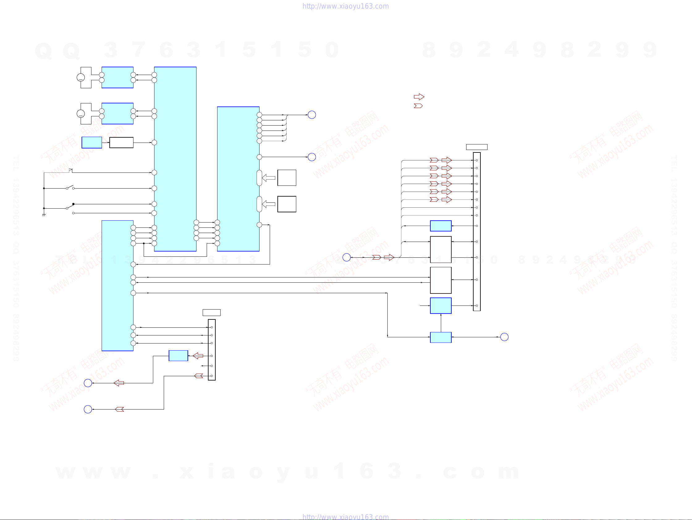
HCD-HDX275/HDX277WC/HDX279W/HDX475/HDX576WF/HDX675
HCD-HDX275/HDX277WC/HDX279W/HDX475/HDX576WF/HDX675
2929
6-2. BLOCK DIAGRAM - CHANGER/HDMI/DMPORT Section -
TX0P
TX0N
TX1P
TX1N
TX2P
TX2N
TCKP
TCKN
7
TMDS DATA0 +
HDMI OUT
9
TMDS DATA0 –
4
TMDS DATA1 +
6
TMDS DATA1 –
1
TMDS DATA2 +
3
TMDS DATA2 –
10
TMDS CLOCK +
12
TMDS CLOCK –
16
SDA
15
SCL
18
+5V POWER
19
HPD
HPD
CN1701
5
RXD
6
TXD
7
DET
13
Lch
14
RchR-CH
17
VIDEO
CN204
DMPORT
LEVEL SHIFT
IC1705
LINE AMP
IC202
LEVEL SHIFT
Q1701
13
CEC
+5V
REGULATOR
IC1707
SW+9V
SDA
SCL
C
HDMI BUS
DMPORT_VIDEO
G
D
DMPORT_L
F
XRST
IO_DI
P0FIN
CHANGER CONTROL
IC650
247
P1RIN
23
OUT1
4
OUT2
2 9
LD/ST MOTOR DRIVER
IC701
M761
(LD/ST MOTOR)
D SENSOR
IC751
(ST U/D)
ROTARY
ENCODER
S781
M
P4FIN 207
P5RIN
19
P8
12
OUT1
4
OUT2
2 9
BU U/D MOTOR DRIVER
IC711
M762
(BU U/D MOTOR)
M
S761 (SUB TRAY OUT)
P11
9
S731 (SUB TRAY IN)
S721 (MAIN TRAY IN/OUT)
P10
10
P911
P12
IN
OPEN
8
86
DMPORT_TX_OUT
30
DMPORT_RX_IN
29
DMPORT_DET
89
DI1
26
IO_CLK
88 CLK3
IO_CE
84 LATCH4
IO_RESET
85
DO1
15
DO2
25
CLKO
14
LATCHO
13
RESET_B
2
CEC_TX_OUT
22
CEC_RX_IN
3
HDMI_PCONT
63
IO-DO
87
CHANGER CONTROL,
AUDIO/VIDEO CONTROL
IC651
DI1
26
DI2
16
CLK
3
LATCH
4
RESET_B
2
DISC SENSOR
Q751
DO2
25
9 – 12
P11 – P8
(MD)
ROTARY
ENCODER
S771
5 – 8
P15 – P12
SYSTEM
CONTROLLER
IC501 (2/5)
• SIGNAL PATH
:AUDIO
:VIDEO
• R-CH is omitted due to same as L-CH.
CEC DATA
SWITCH
Q9724, 9726,
Q9728, 9729
P6
18
P7
17
A_SEL0
A_SEL1
P4
20
P5
19
A_SEL2
A_SEL3
P2
22
P3
21
A_SEL4
A_SEL5
E
J
P1
23
V_SEL2
A_SEL
LEVEL SHIFT
IC1706
(Page 30)
(Page 28)
(Page 30)
(Page 28)
(Page 28)
(Page 28)
Q
Q
3
7
6
3
1
5
1
5
0
8
9
2
4
9
8
2
9
9
TEL 13942296513 QQ 376315150 892498299
1
3
9
4
2
2
9
T
E
L
6
5
1
3
TEL 13942296513 QQ 376315150 892498299
9
9
2
8
9
4
2
9
0
5
1
5
1
3
6
7
3
Q
Q
8
.
x
w
w
w
i
a
o
y
u
1
6
3
.
c
o
m
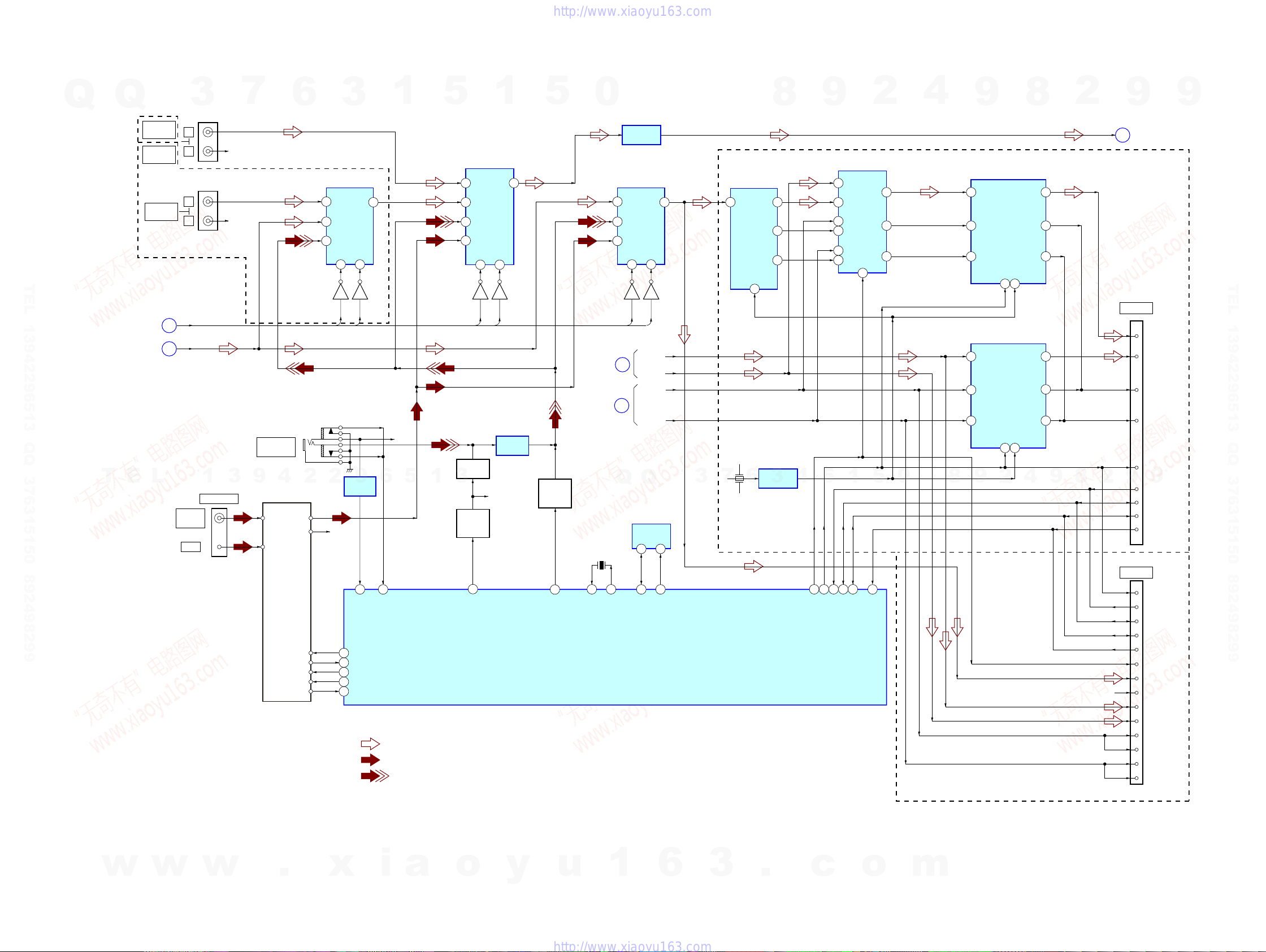
HCD-HDX275/HDX277WC/HDX279W/HDX475/HDX576WF/HDX675
HCD-HDX275/HDX277WC/HDX279W/HDX475/HDX576WF/HDX675
3030
6-3. BLOCK DIAGRAM - TUNER/S-AIR Section -
A_SEL4
A_SEL5
A_SEL0
A_SEL1
A_SEL2
A_SEL3
AUDIO SELECTOR
IC411
R-CH
R-CH
72 ST_DI
91
MONO/ST_DET
90
A.CAL_MIC
_LEVEL
28
DC_CONT
70 ST_DO
69 ST_CLK
71 ST_CE
68 TUNED
R-CH
TUNER (FM/AM)
AM
FM ANT
AM ANT
L-CH
R-CH
DIN
TUNED
DO
CLK
CE
FM 75Ω
COAXIAL
ANTENNA
4Y3
2 3Y2 Y
1Y0
10A9
B
J405
(HCD-HDX576WF)
(EXCEPT HCD-HDX576WF)
J402 (2/2)
TV
AUDIO IN
TV/VIDEO
AUDIO IN
L
R
R-CH
SAT/CABLE
AUDIO IN
L
R
R-CH
Q413
Q412
LINE AMP
IC410
XIN
15
XOUT
13
S-AIR_ADC_SEL
54
S-AIR_RST(SRC RST)
58
S-AIR_I2C_SDA
77
S-AIR_I2C_SCL
78
S-AIR_GPIO_2
67
X501
5MHz
SYSTEM CONTROLLER
IC501 (3/5)
• SIGNAL PATH
: TUNER
: AUDIO
• R-ch is omitted due to same as L-ch.
: AUDIO IN
AUDIO IN/
A.CAL MIC
J100
5Y1
DATA SELECTOR
IC801
31B
2
41A1Y
72Y
93Y
6
2B
1
SEL
5
2A
10
3B
11
3A
ASYNC SAMPLE
RATE CONVERTER
IC804
6
LRCKI
4
23
SDIN
SDOUT
25BCKO
24LRCKO
5
BCKI
13
RST
2
RCKI
ASYNC SAMPLE
RATE CONVERTER
IC803
6
LRCKI
4
23
SDIN
SDOUT
25BCKO
24LRCKO
5
BCKI
13
RST
2
RCKI
LINE AMP
IC104
LINE AMP
IC105
MUTING
Q115
MUTING
CONTROL
Q111
GAIN
CONTROL
Q112, 113
MIC_GAIN
26
G
DMPORT_L
J
A_SEL
AUDIO SELECTOR
IC409
5
3Y1Y
11 Y0
10A9
B
2Y2
AUDIO SELECTOR
IC407
5
3Y1Y
11 Y0
10A9
B
2Y2
A/D CONVERTER
IC805
9VOUT
8BCK
7LRCK
13 VINL
Q409
Q408
D4
D2
BCK
LRCK
Q411
Q410
B
M
K
X800
12.288MHz
OSC BUFFER
IC802
17
BCK
15
LRCK
12
RESET
RESN
GPI02
I2D_SCL
I2D_SDA
GND
ADC_SEL
Lch
Rch
SD1
SD2
BCK1
BCK2
LRCK1
LRCK2
7
INIT
11
I2D_SCL
14
3
I2D_SDA
GND (for DET)
CN803
EZW-RT10
CN113
EZW-T100
13
SDIN_B(Surr)
20
7
11
19
18
15
26
24
23
14
4
12
16
2
SDIN_A(2nd)
(HCD-HDX277WC/HDX279W/HDX576WF)
AUDIO1
6
SCKI
25
R-CH
(HCD-HDX275/HDX475/HDX675)
EEPROM_SDA/I2C_DATA
EEPROM_SCL/I2C_CLK
47 48
EEPROM
IC510
5 6
SDA
SCL
(MIC_/A.CAL_SW)/
(HP_SW and MIC2_SW)/S-AIR_DET
66
(Page 29)
(Page 29)
(Page 28)
(Page 31)
(Page 28)
Q
Q
3
7
6
3
1
5
1
5
0
8
9
2
4
9
8
2
9
9
TEL 13942296513 QQ 376315150 892498299
T
w
E
L
w
1
w
3
9
4
.
2
2
x
9
6
5
i
a
1
3
o
y
u
Q
1
Q
6
3
3
3
6
7
.
1
5
c
1
5
o
0
m
4
2
9
8
9
8
2
9
TEL 13942296513 QQ 376315150 892498299
9
 Loading...