

Sony HCD-GZR5D Schematic
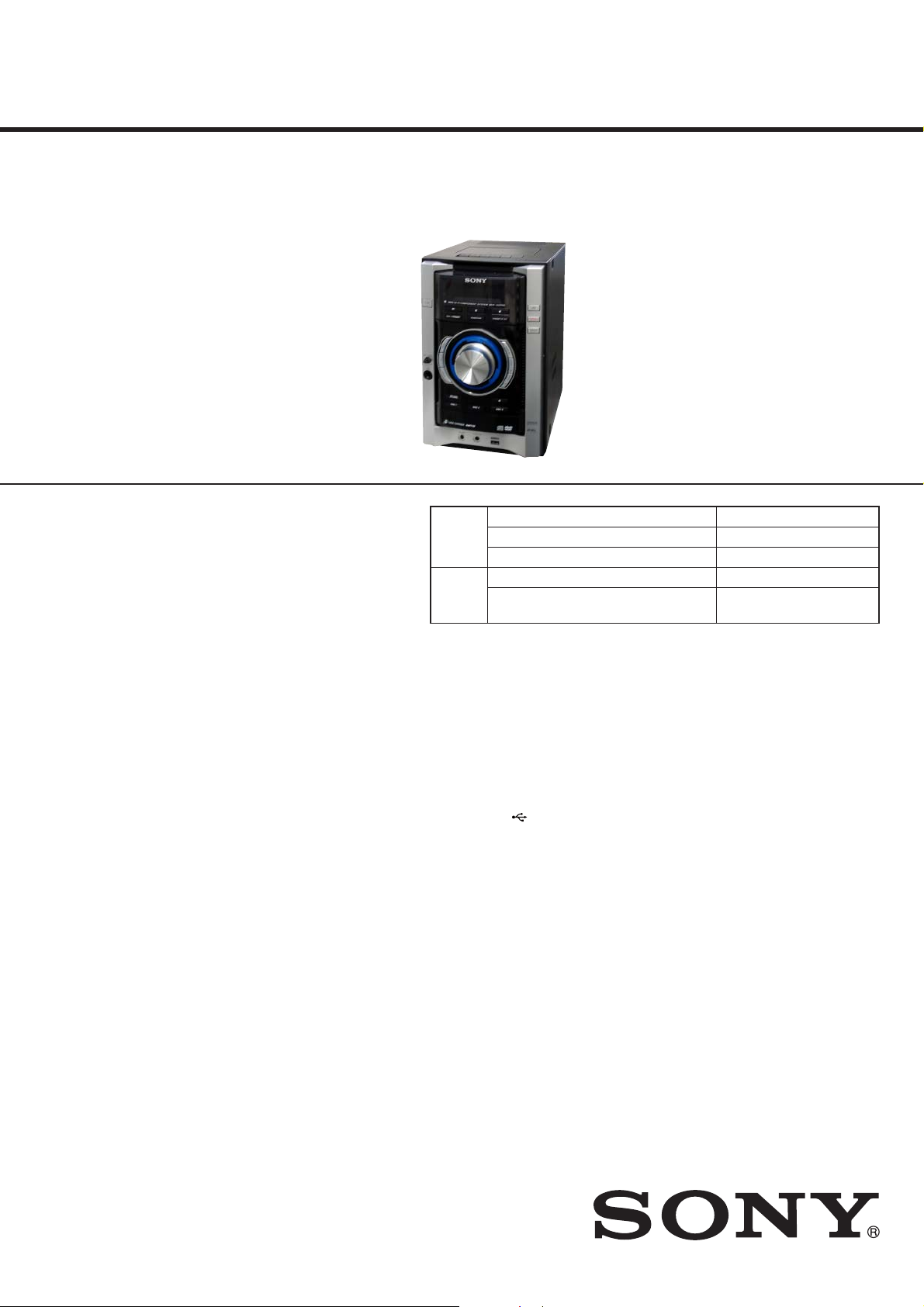
HCD-GZR5D
SERVICE MANUAL
Ver. 1.0 2008.05
• HCD-GZR5D is the Amplifi er,
DVD player, tape deck, and tuner
section in MHC-GZR5D.
DVD
Section
TAPE
Section
UK Model
E Model
Model Name Using Similar Mechanism HCD-GNZ333D/GNZ444D
DVD Mechanism Type CDM74HF-DVBU101
Optical Pick-up Name KHM-313CAB/C2RP
Model Name Using Similar Machanism HCD-GT444
Tape Transport Mechanism T ype
TCM-J1 or
CS-21SC-900TP
SPECIFICATIONS
Amplifi er Section
The following are measured at AC 230 V, 50/60 Hz
(European and Russian models)
The following measured at AC 127, 240 V, 50/60 Hz
(Saudi Arabian model)
The following measured at AC 120, 220, 240 V, 50/60 Hz (Other models)
Power output (rated): 72 W + 72 W
(6 Ω, 1 kHz, 1% THD)
RMS output power (reference)
120 W + 120 W
(per channel at 6 Ω, 1 kHz, 10% THD)
Inputs
AUDIO IN (stereo mini jack):
Voltage 700 mV, impedance 47 kilohms
MIC (phone jack): Sensitivity 2 mV, impedance 10 kilohms
Outputs
VIDEO OUT (phone jack):
Max. output level 1 Vp-p, unbalanced, Sync.
negative, load impedance 75 ohms
DVD DIGTAL OUT (Square optical connector jack, rear panel):
Wavelength 650 nm
PHONES (stereo mini jack):
accepts headphones of 8 ohms or more
USB section
Supported bit rate MP3 (MPEG 1 Audio Layer-3): 32 – 320 kbps
WMA: 48 – 192 kbps
AAC: 48 – 320 kbps
Sampling frequencies
MP3 (MPEG 1 Audio Layer-3): 32/44.1/48 kHz
WMA: 44.1 kHz
AAC: 44.1 kHz
(USB) port: Maximum current: 500 mA
Disc player section
System : Compact disc and digital audio and video system
Laser Diode Properties
Emission duration: Continuous Laser Output*:
Less than 44.6 μW
*This output is the value measurement at a distance
of 200 mm from the objective lens surface on the
Optical Pick-up Block with 7 mm aperture.
Frequency response DVD (PCM 48 kHz): 2 Hz – 22 kHz (±1 dB)
CD: 2 Hz – 20 kHz (±0.5 dB)
Video color system format
European and Russian models: PAL
Other models: NTSC and PAL
Tape deck section
Recording system: 4-track 2-channel stereo
– Continued on next page –
9-889-161-01
2008E04-1
2008.05
©
DVD DECK RECEIVER
Sony Corporation
Audio Business Group
Published by Sony Techno Create Corporation
HCD-GZR5D
Tuner section
FM stereo, FM/AM superheterodyne tuner
FM tuner section
Tuning range: 87.5 – 108.0 MHz (50 kHz step)
Antenna: FM lead antenna
Antenna terminals: 75 ohms unbalanced
Intermediate frequency: 10.7 MHz
AM tuner section
Tuning range: European, Russian and Saudi Arabian models:
531 – 1,602 kHz (9 kHz step)
Other models:
531 – 1,602 kHz (with 9 kHz tuning interval)
530 – 1,610 kHz (with 10 kHz tuning interval)
Antenna: AM loop antenna
Antenna terminals: External antenna terminal
Intermediate frequency: 450 kHz
General
Power requirements
European model: AC 230 V, 50/60 Hz
Thai model: AC 220 V, 50/60 Hz
Other models: AC 120, 220, 230 – 240 V, 50/60 Hz, adjustable
with voltage selector
Power consumption: 190 W
Dimensions (w/h/d) (excl. speakers):
Approx. 200 × 306 × 415 mm
Mass (excl. speakers): Approx. 7.9 kg
Design and specifi cations are subject to change without notice.
NOTES ON HANDLING THE OPTICAL PICK-UP
BLOCK OR BASE UNIT
The laser diode in the optical pick-up block may suffer electrostatic break-down because of the potential difference generated by the
charged electrostatic load, etc. on clothing and the human body.
During repair, pay attention to electrostatic break-down and also
use the procedure in the printed matter which is included in the
repair parts.
The fl exible board is easily damaged and should be handled with
care.
NOTES ON LASER DIODE EMISSION CHECK
The laser beam on this model is concentrated so as to be focused
on the disc refl ective surface by the objective lens in the optical
pickup block. Therefore, when checking the laser diode emission,
observe from more than 30 cm away from the objective lens.
LASER DIODE AND FOCUS SEARCH OPERATION
CHECK
Carry out the “S curve check” in “CD section adjustment” and
check that the S curve waveform is output several times.
CAUTION
Use of controls or adjustments or performance of procedures
other than those specifi ed herein may result in hazardous radia-
tion exposure.
This appliance is classifi ed as
a CLASS 1 LASER product.
This marking is located on the
rear or bottom exterior.
NOTES ON CHIP COMPONENT REPLACEMENT
• Never reuse a disconnected chip component.
• Notice that the minus side of a tantalum capacitor may be damaged by heat.
FLEXIBLE CIRCUIT BOARD REPAIRING
• Keep the temperature of soldering iron around 270 °C during
repairing.
• Do not touch the soldering iron on the same conductor of the
circuit board (within 3 times).
• Be careful not to apply force on the conductor when soldering
or unsoldering.
SAFETY-RELATED COMPONET WARNING!
COMPONENTS IDENTIFIED BY MARK 0 OR DOTTED LINE
WITH MARK 0 ON THE SCHEMATIC DIAGRAMS AND IN
THE PARTS LIST ARE CRITICAL TO SAFE OPERATION.
REPLACE THESE COMPONENTS WITH SONY PARTS
WHOSE PART NUMBERS APPEAR AS SHOWN IN THIS
MANUAL OR IN SUPPLEMENTS PUBLISHED BY SONY.
2
HCD-GZR5D
UNLEADED SOLDER
Boards requiring use of unleaded solder are printed with the leadfree mark (LF) indicating the solder contains no lead.
(Caution: Some printed circuit boards may not come printed with
the lead free mark due to their particular size)
: LEAD FREE MARK
Unleaded solder has the following characteristics.
• Unleaded solder melts at a temperature about 40 °C higher
than ordinary solder.
Ordinary soldering irons can be used but the iron tip has to be
applied to the solder joint for a slightly longer time.
Soldering irons using a temperature regulator should be set to
about 350 °C.
Caution: The printed pattern (copper foil) may peel away if
the heated tip is applied for too long, so be careful!
• Strong viscosity
Unleaded solder is more viscous (sticky, less prone to fl ow)
than ordinary solder so use caution not to let solder bridges
occur such as on IC pins, etc.
• Usable with ordinary solder
It is best to use only unleaded solder but unleaded solder may
also be added to ordinary solder.
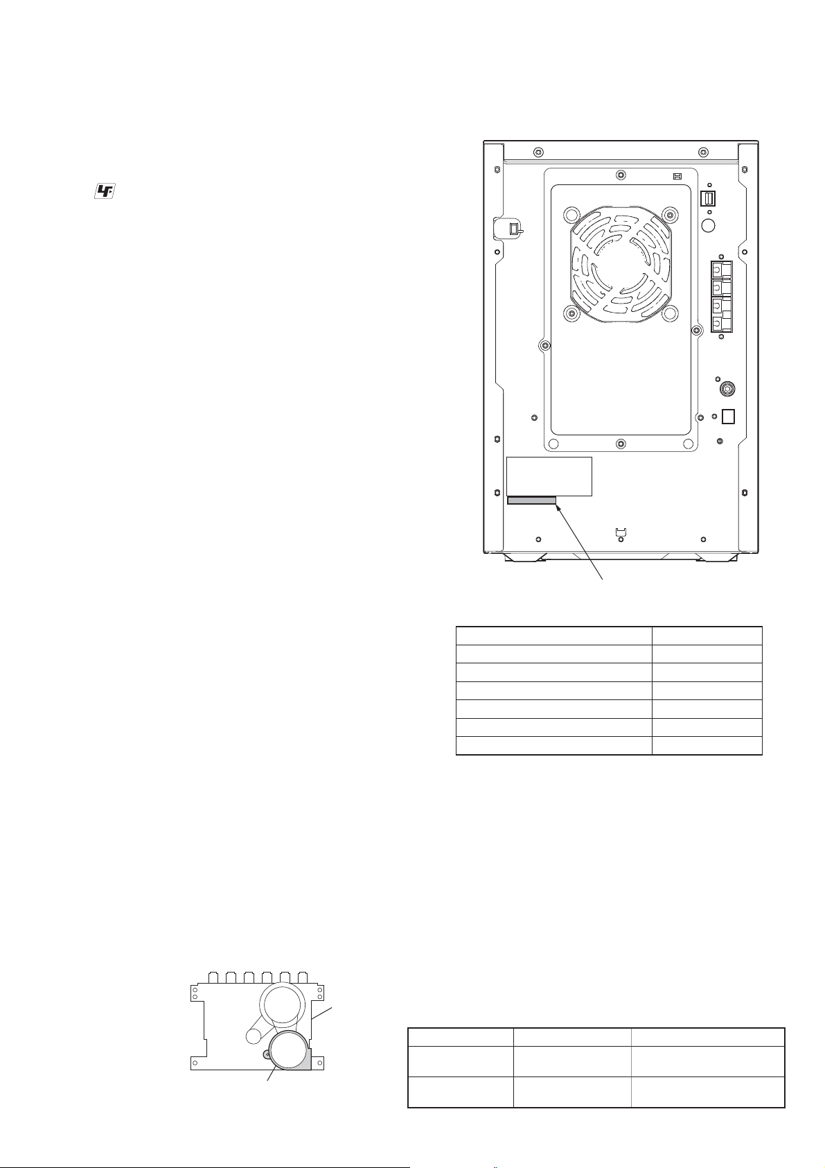
MODEL IDENTIFICATION
-Back Panel-
Parts No.
Model Part No.
SP model
E3, E15 models
PH model
TH model
E12 model
UK model
• Abbreviation
E3 : 240V AC area in E model
E12 : 220 – 240V AC area in E model
E15 : Iran model
PH : Philippines model
SP : Singapore model
TH : Thai model
3-289-544-0[]
3-289-544-3[]
3-289-544-4[]
3-289-544-5[]
3-289-544-6[]
3-289-544-7[]
HOW TO DISTINGUISH TAPE MECHANISM DECK
Two kinds of tape mechanism decks installed by this set exist.
Please do the repair exchange after confi rming which tape mechanism deck set of the repair according to how to distinguish the fi gure
below.
motor
Metal part: TCM-J1
Mold part: CS-21SC-900TP
tape deck
Tape Deck Name Tape Deck Part No. Belt Part No.
TCM-J1
CS-21SC-900TP
A-1527-851-A
1-797-575-11
2-670-389-01 BELT (1)
3-214-817-01 BELT (FR)
2-688-621-01 BELT (R/F)
2-688-622-01 BELT (MAIN)
3

HCD-GZR5D
TABLE OF CONTENTS
1. SERVICING NOTES .............................................. 5
1-1. CDM Service Position .................................................... 5
1-2. Opening The Try Manual ................................................ 5
1-3. Note for Handling The BU ............................................. 6
1-4. Arrangement of The Coad .............................................. 6
2. GENERAL
Guide to Parts and Controls ............................................ 7
3. DISASSEMBLY
3-1. Side Panel (R), Side Panel (L) ........................................ 15
3-2. Top Panel Section ........................................................... 15
3-3. Door (CD) ....................................................................... 16
3-4. Front Panel Section ........................................................ 16
3-5. Main Board ..................................................................... 17
3-6. DC Fan ............................................................................ 17
3-7. Rear Panel ....................................................................... 18
3-8. AMP Board ..................................................................... 18
3-9. PT Board ......................................................................... 19
3-10. Cover (CDM) .................................................................. 19
3-11. DVD Mechanism Section ............................................... 20
3-12. DMB18 Board ................................................................. 20
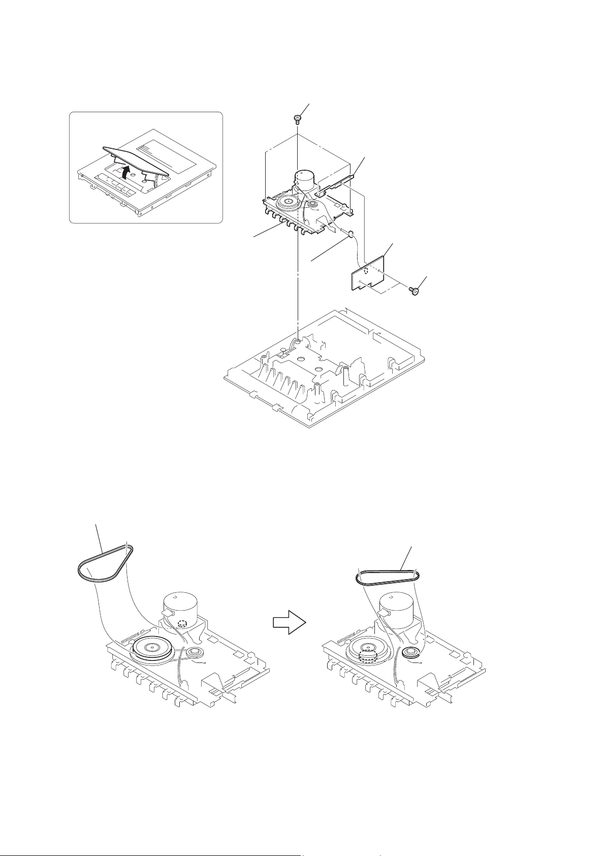
3-13. Optical Pick-up ............................................................... 21
3-14. Belt (DLM3A) ................................................................ 21
3-15. Mechanism Deck ............................................................ 22
3-16. Belt (Main), Belt (R/F) ................................................... 22
4. TEST MODE ....................................................... 23
7-5. Circuit Boards Location .................................................. 36
7-6. Printed Wiring Board – Main Section – .......................... 37
7-7. Schematic Diagram – Main Section (1/3) – .................... 38
7-8. Schematic Diagram – Main Section (2/3) – .................... 39
7-9. Schematic Diagram – Main Section (3/3) – .................... 40
7-10. Schematic Diagram – DMB Section (1/5) – ................... 41
7-11. Schematic Diagram – DMB Section (2/5) – ................... 42
7-12. Schematic Diagram – DMB Section (3/5) – ................... 43
7-13. Schematic Diagram – DMB Section (4/5) – ................... 44
7-14. Schematic Diagram – DMB Section (5/5) – ................... 45
7-15. Printed Wiring Board – DMB Section (1/2) – ................ 46
7-16. Printed Wiring Board – DMB Section (2/2) – ................ 47
7-17. Printed Wiring Board – Deck Section – .......................... 48
7-18. Schematic Diagram – Deck Section – ............................ 49
7-19. Printed Wiring Board – AMP Section – .......................... 50
7-20. Schematic Diagram – AMP Section –............................. 51
7-21. Printed Wiring Boards – USB Section – ......................... 52
7-22. Schematic Diagram – USB Section – ............................. 53
7-23. Printed Wiring Board – Panel Section – ......................... 54
7-24. Schematic Diagram – Panel Section – ............................ 55
7-25. Printed Wiring Boards – Key Section – .......................... 56
7-26. Schematic Diagram – Key Section – .............................. 57
7-27. Printed Wiring Boards – MIC/Jack Section – ................. 58
7-28. Schematic Diagram – MIC Section – ............................. 59
7-29. Schematic Diagram – Jack Section – .............................. 60
7-30. Printed Wiring Board – PT Section – ............................. 61
7-31. Schematic Diagram – PT Section – ................................ 62
7-32. Schematic Diagram – Reg Section – .............................. 63
5. MECHANICAL ADJUSTMENTS ..................... 27
6. ELECTRICAL ADJUSTMENTS ...................... 27
7. DIAGRAMS
7-1. Block Diagram – RF/Servo Section – ............................. 31
7-2. Block Diagram – Video Section – .................................. 32
7-3. Block Diagram – Main Section – ................................... 33
7-4. Block Diagram – Display Section – ............................... 34
8. EXPLODED VIEWS
8-1. Overall Section ............................................................... 78
8-2. Front Panel Section ......................................................... 79
8-3. Main Board Section ........................................................ 80
8-4. Rear Panel Section .......................................................... 81
8-5. Chassis Section ............................................................... 82
8-6. Top Panel Section ........................................................... 83
8-7. DVD Mechanism Deck Section ...................................... 84
9. ELECTRICAL PARTS LIST ............................ 85
4
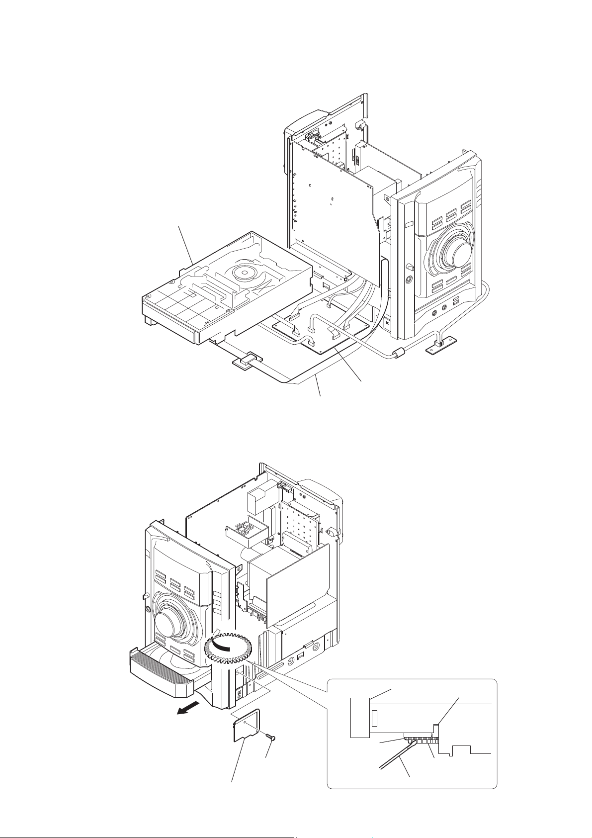
1-1. CDM SERVICE POSITION
CDM mechanism block
HCD-GZR5D
SECTION 1
SERVICING NOTES
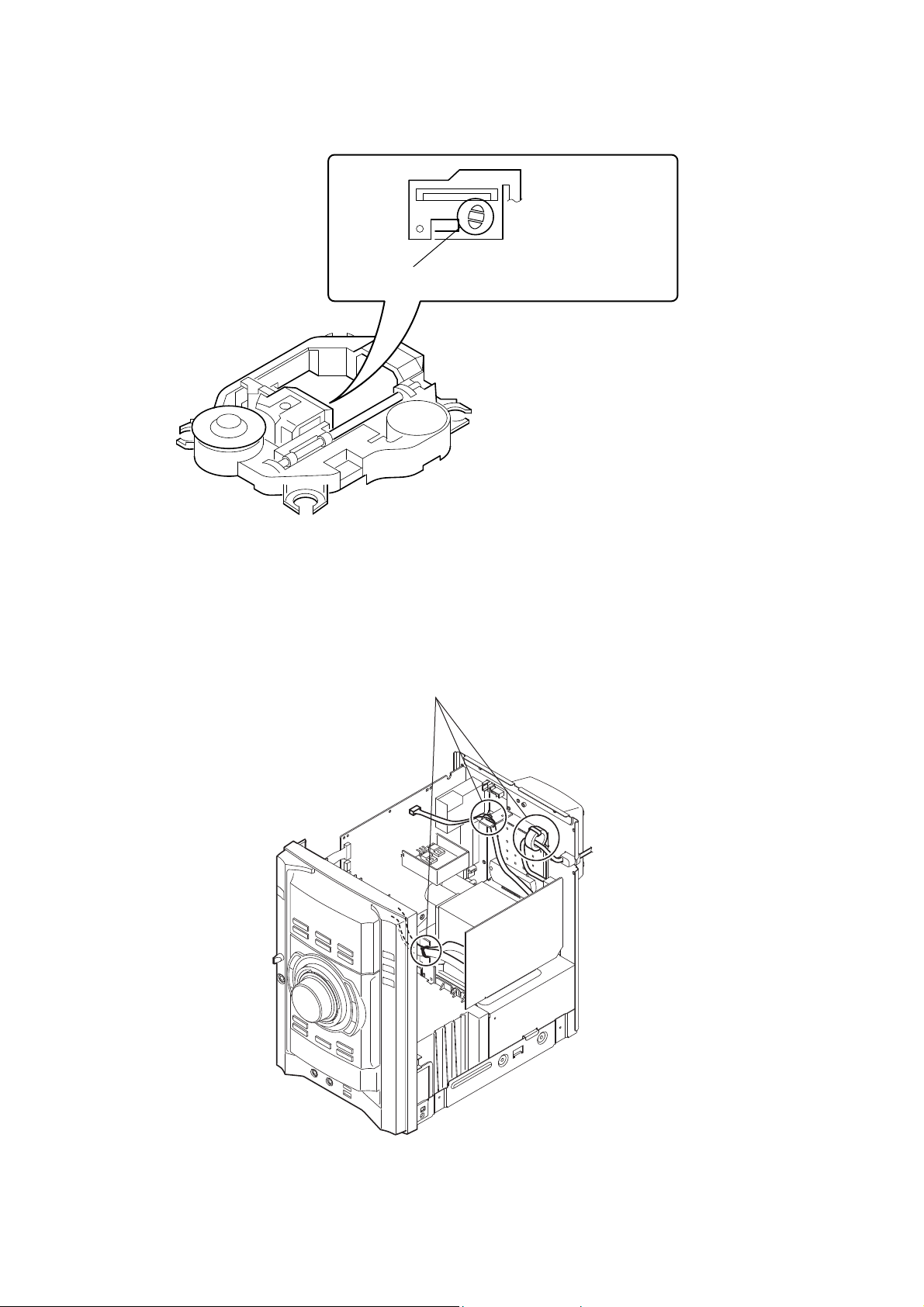
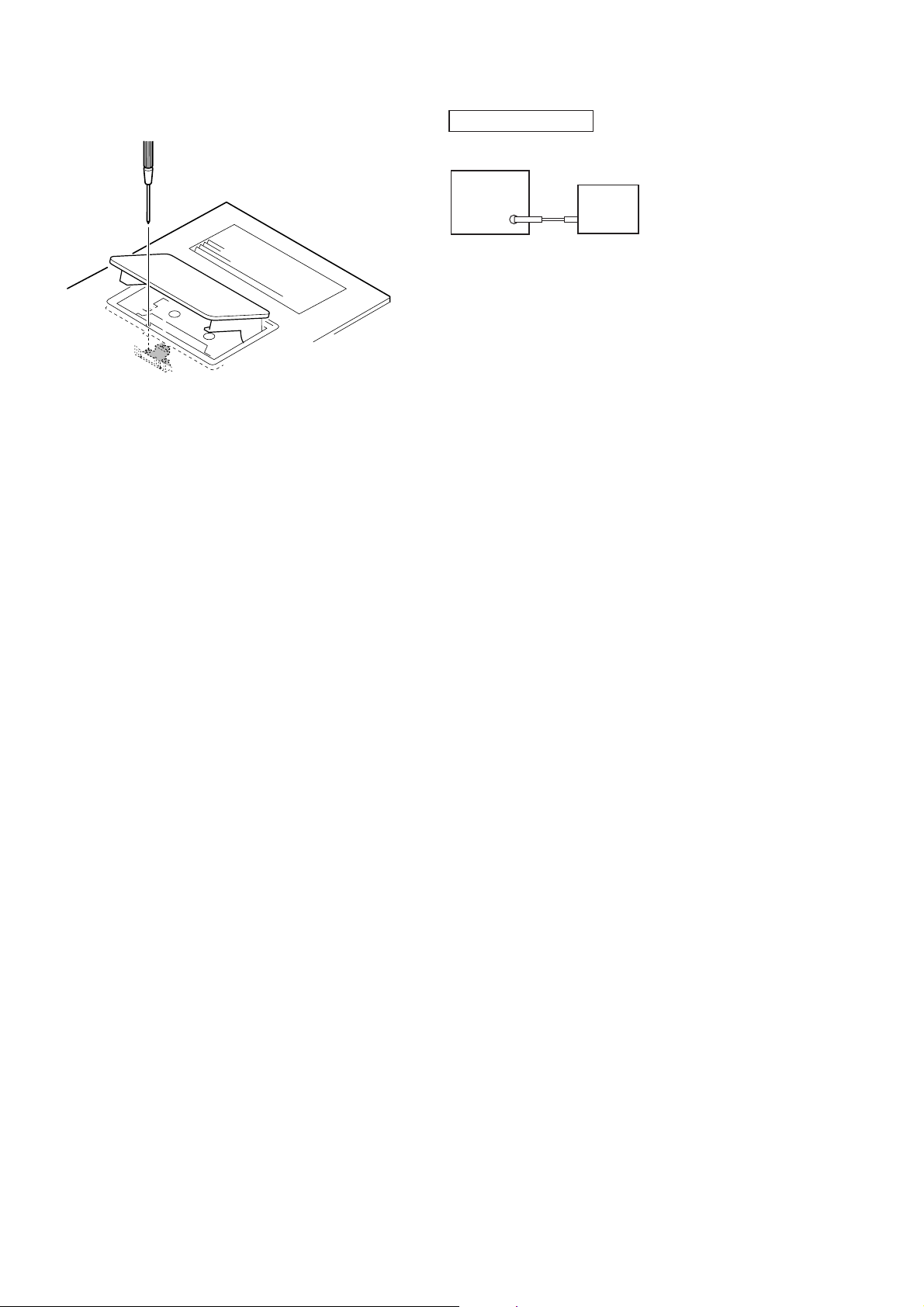
1-2. OPENING THE CD TRAY MANUAL
"
DMB18 board
J-2501-077-A
(1.25m/13P/300L)
Turn the bottom rib (not the gear) with
a flathead screwdriver in the direction
of arrow A, with the lever pushed up,
draw out the door (CD) by the hand.
door (CD)
lever
lid CDM cover
screw
+BVTP 3 × 10
(
gear
bottom rib
)
flathead screwdriver
5
HCD-GZR5D
1-3. NOTE FOR HANDLING THE BU
Perform solder bridging to prevent damage by electrostatic
discharge when handling the BU as a single unit.
1-4. ARRANGEMENT OF THE CORD
cordes are fixed
6
SECTION 2
GENERAL
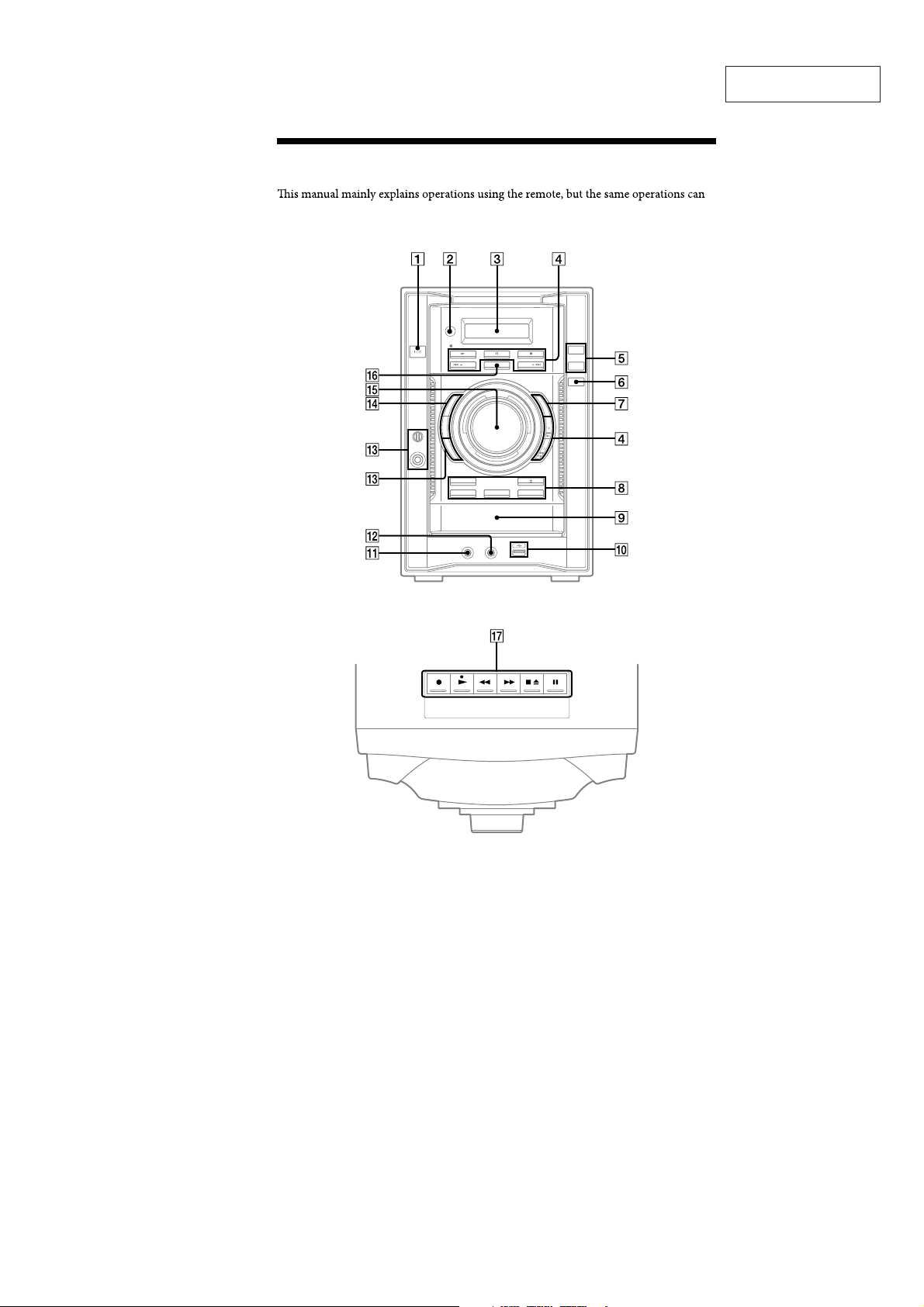
Guide to parts and controls
also be performed using the buttons on the unit having the same or similar names.
Unit
HCD-GZR5D
This section is extracted
from instruction manual.
12
Top panel
GB
7
HCD-GZR5D
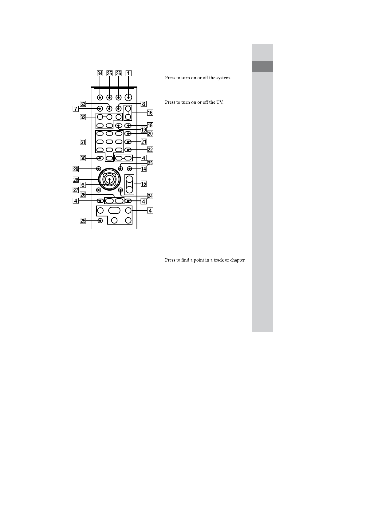
Remote
(on/standby) (63, 86, 105)
1)
Remote: TV
(on/standby)
(24)
Remote sensor
Display
Unit: / (play) (22, 28, 71)
Remote: )
Presstostartplayback.
2)
(play) (28, 71)
9 (pause) (23, 29)
Presstopauseplayback.
Y (stop) (29, 58, 61, 63)
Presstostopplayback.
/ (go backward/
forward) (26, 27, 29, 72)
Presstoselect a trackorchapter.
Guide to parts and controls
N/. (rewind/fast forward)
(29)
Continued
M
13
GB
8

HCD-GZR5D
Remote: +/− (27, 29)
Press to select a folder.
Unit: / (29)
Remote:
Press to watch the slow-motion play.
SLOW/SLOW (29)
TUNING +/− (57, 58, 59)
Press to tune in the desired station.
PRESET +/− (58)
Press to select the preset station.
Remote: TV CH +/−1) (24)
PresstochangetheTVchannels.
USB (65, 69)
Press to select the “USB” function.
REC TO USB (63, 67)
Press to transfer music from a disc or
record the sound from an analog audio
source to the connected optional USB
device.
Presstomarktracknumbersduring
recording.
ENTER (24, 26, 29, 34, 39, 43, 47,
48, 51, 57, 63, 67, 71, 82, 85)
Press to enter the settings.
DISPLAY (23, 25, 59, 87, 88)
Press to display the disc information or
clock in the front panel display.
Unit: ; (open/close) (28)
Press to load or eject a disc.
Unit: EX-CHANGE/DISC SKIP (30)
Press to select a disc.
Press to exchange a disc while playing.
Remote: DISC SKIP (30, 63)
Press to select a disc.
Unit: DISC 1 − DISC 3 (30, 61, 63,
105)
Press to select a disc.
Press to switch to the “DVD” function
from other function.
Disc tray
+
(USB) port (62, 67, 69, 86)
Connect an optional USB device.
(USB) indicator (74)
Lights up in red when transferring or
recording to the connected optional USB
device or when erasing audio tracks or
folders.
14
GB
9

HCD-GZR5D
,
PHONES jack
Connect the headphones.
-
AUDIO IN jack (93)
Connect an optional audio component.
.
ECHO (80)
Press to adjust the echo level.
MIC jack (61, 80)
Connect a microphone.
MIC LEVEL (80)
Turn to adjust the microphone volume.
/
Unit: DSGX (78, 105)
Presstoreinforcethebass.
Unit: EQ (78)
Remote: SOUND FIELD (78)
surround sound.
0
Unit: VOLUME (28, 81, 85)
Turn to adjust the volume.
Remote: VOLUME +/−2) (28, 81,
85)
Press to adjust the volume.
Remote: TV VOL +/−
Pressto adjusttheTVvolume.
1)2)
(24)
1
Unit: FUNCTION (22, 23, 25, 28,
57, 60, 61, 63, 67, 69, 80)
Remote: FUNCTION +/− (23, 25,
28, 57, 60, 63, 67, 69, 80)
Presstoselectthefunction.
2
[ (record) (61)
Press to record on a tape.
/ (play) (60)
Press to start playback of a tape.
N. (rewind/fast forward)
(60)
Press to rewind or fast forward a tape.
Y; (stop/eject) (60)
Press to stop playback of a tape.
Press to insert or eject a tape.
9 (pause) (60)
Press to pause playback of a tape.
3
PICTURE NAVI (44, 73)
Press to display the thumbnail pictures.
Guide to parts and controls
10
Continued
M
15
GB

HCD-GZR5D
4
REPEAT/FM MODE (38, 59, 77)
Press to listen to a disc, an USB device, a
Press to select FM reception mode
(monaural or stereo).
5
AUDIO (31, 80)
Press to display the current audio signal
on the TV screen.
6
SUBTITLE (30)
Press to switch the language of the
subtitle (DVD VIDEO only).
D. TUNING (58)
Press to switch to the direct tuning mode.
7
ANGLE (30)
Press to change the angle (DVD VIDEO
with multi-angles only).
8
DVD/TUNER MENU (39, 42, 57, 71)
Press to display the menu items on the
TV screen.
Press to preset the radio station.
9
DISPLAY (26, 34, 39, 47, 48, 51,
64, 71, 82, 92, 113)
Press to display the Control Menu on the
TV screen.
when the “DVD” function or “USB”
function is selected.
:
TV1) (24)
Press to operate the TV functions.
;
D STEP $ (29)
Press to play one frame at a time when
playback is paused.
ADVANCE (29, 43, 71)
Press to advance the current scene during
playback.
REPLAY (29, 43, 71)
Press to replay the previous scene during
playback.
XK
0 RETURN (33, 43, 65, 72)
Press to return to the previous menu on
the TV screen.
16
GB
11

HCD-GZR5D
XL
7/W/#/C (24, 34, 35, 39, 57, 64,
78, 85)
Press to select the menu items.
XM
DVD TOP MENU (39)
Press to display the DVD title on the TV
screen.
F
CLEAR (25, 27, 35, 41, 44, 65, 73)
Press to delete a pre-programmed track
Press to erase audio tracks or folders
from the connected optional USB device.
-/--1)(24)
Press to enter a single digit or double
digit number.
FB
Numeric buttons2) (24, 29, 39, 48,
53, 58)
Press to select a track or chapter.
Press to enter a password.
1)
10/0
Press to enter a double digit number.
FT
KEY CONTROL / (81)
Presstochangethekeytosuityourvocal
range.
SCORE (84)
Press to start or stop calculating your
vocal score.
KARAOKE MODE (80)
PresstoselecttheKaraokemode.
KARAOKE PON (82)
Press to activate the “Karaoke Pon”
function.
FE
TIME/TEXT (88, 90)
Press to change the information
appearing in the front panel display or
on-screen display.
FG
SLEEP (27, 85)
Press to set the Sleep Timer.
TV INPUT1) (24)
Press to switch the input sources.
Guide to parts and controls
12
FH
TIMER MENU (24, 85)
Presstosettheclockandthetimers.
FI
THEATRE SYNC (27)
Press to activate the “THEATRE SYNC”
function.
1)
details, see “Operating a Sony TV” (page 24).
2)
VOLUME +
remote have a tactile dot. Use the tactile dot
as a reference when operating the system.
FB
RH
, TV VOL + RH,
and )buttons on the
Continued
M
17
GB
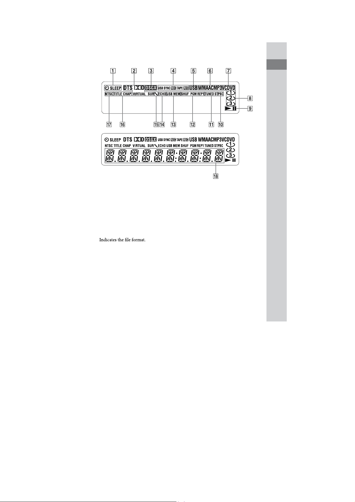
Display
HCD-GZR5D
Guide to parts and controls
Lights up when the timer is set. (85)
Indicates the current surround
format.
Lights up when “DSGX” is turned on.
(78)
Lights up during transfer or
recording. (60, 62, 67)
Lights up when the “USB” function is
selected. (69)
Indicates the type of disc being played
back. (28)
Indicates the disc presence. (28)
Indicatestheplaybackstatusofthe
disc or USB device.
R Lights up when playing VIDEO CD
with PBC function. (32)
RB Lights up in “TUNER” function. (57)
RT Indicates the selected play mode. (34)
RE Lights up when the USB device is
recognized. (69)
RG Lights up when the microphone echo
is turned on.
RH Lights up when the Karaoke Mode is
turned on. (80)
RI Lights up when the title or chapter
number is displayed.
RK Lights up when the output video
signal is NTSC. (23)
RL Displays the text information.
19
GB
13
HCD-GZR5D
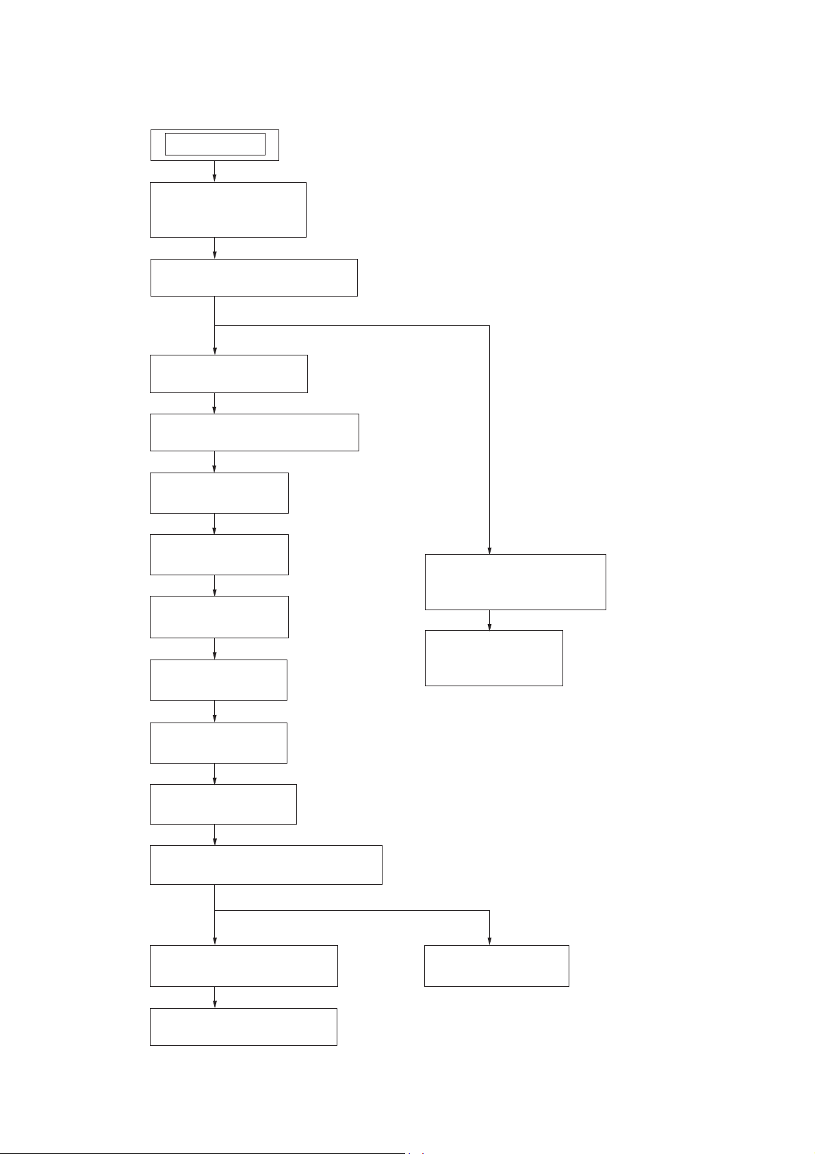
DISASSEMBLY
• This set can be disassembled in the order shown below.
SET
3-1. SIDE PANEL (R),
SIDE PANEL (L)
(Page 15)
3-2. TOP PANEL SECTION
(Page 15)
3-3. DOOR (CD)
(Page 16)
3-4. FRONT PANEL SECTION
(Page 16)
SECTION 3
3-5. MAIN BOARD
(Page 17)
3-6. DC FAN
(Page 17)
3-7. REAR PANEL
(Page 18)
3-8. AMP BOARD
(Page 18)
3-9. PT BOARD
(Page 19)
3-10. COVER (CDM)
(Page 19)
3-11. DVD MECHANISM SECTION
(Page 20)
3-15. MECHANISM DECK
(Page 22)
3-16. BELT (MAIN),
BELT (R/F)
(Page 22)
14
3-12. DMB18 BOARD
(Page 20)
3-13. OPTICAL PICK-UP
(Page 21)
3-14. BELT (DLM3A)
(Page 21)
Note: Follow the disassembly procedure in the numerical order shown below.
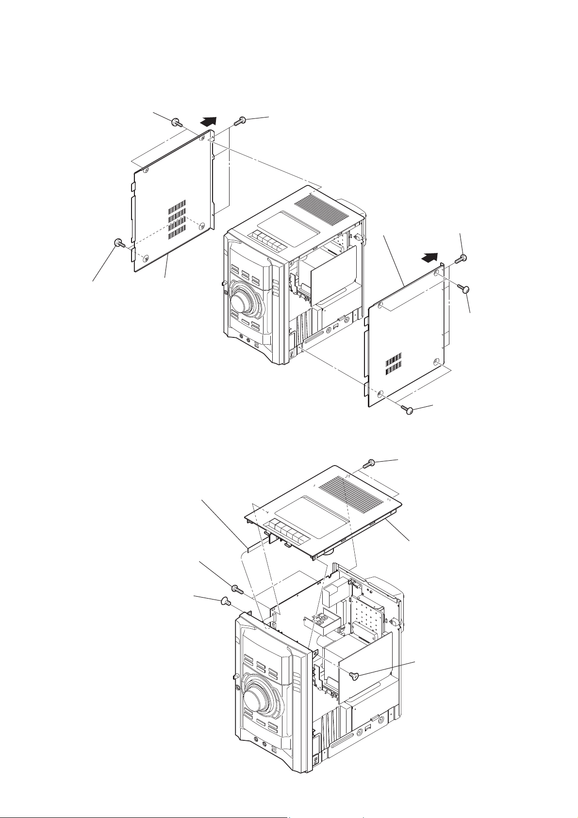
3-1. SIDE PANEL (R), SIDE PANEL (L)
two
screws
(case 3 TP2)
three screws
(+BVTP 3 × 10)
HCD-GZR5D
two
screws
(case 3 TP2)
side panel (L)
3-2. TOP PANEL SECTION
wire (flat type) (9 core)
(CN102)
side panel (R)
two screws
(+BVTP 3 × 10)
four screws
(+BVTP 3 × 10)
two
(case 3 TP2)
two
screws
(case 3 TP2)
screws
two screws
(+BVTP 3 × 10)
screw
(+KTP 3 × 10)
top panel section
screw
(+KTP 3 × 10)
15
HCD-GZR5D
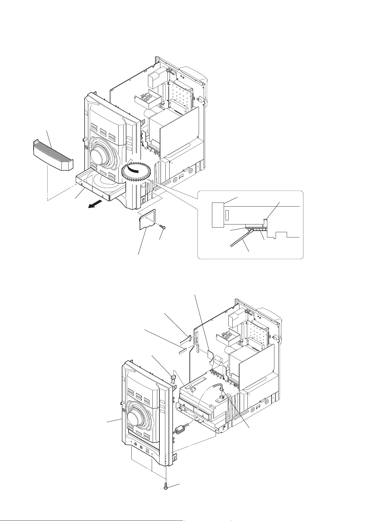
3-3. DOOR (CD)
door (CD)
tray
"
Turn the bottom rib (not the gear) with
a flathead screwdriver in the direction
of arrow A, with the lever pushed up,
draw out the door (CD) by the hand.
door (CD)
lever
3-4. FRONT PANEL SECTION
wire (flat type) (9 core)
(CN103)
lid CDM cover
CN407 (4P)
screw
(
+BVTP 3 × 10
CN101 (8P)
gear
bottom rib
)
flathead screwdriver
wire (flat type) (17 core)
(CN402)
16
front panel section
three screws
(+BVTP 3 × 10)
CN823 (3P)
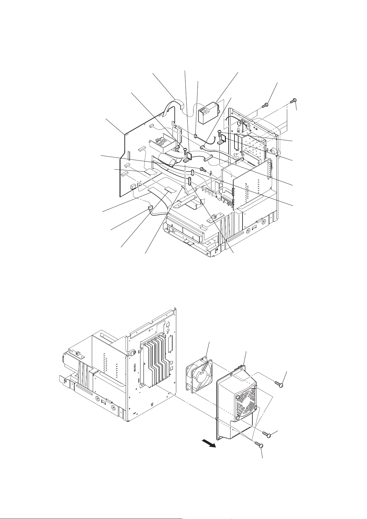
3-5. MAIN BOARD
HCD-GZR5D
RB
(
X
MAIN board
screw
(
+BVTP 3 × 10
wire (flat type) (23core)
(CN406)
wire (flat type) (13 core)
(CN403)
)
CN401 (5P)
wire (flat type) (9 core)
(connector)
screw
+BVTP 3 × 10
)
RT
REG B board
RM
CN105 (3P)
tuner (FM/AM)
(TN001)
CN107 (4P)
two screws
(+BVTP 2.6 × 8)
RH four
screws
(
+BVTP 3 × 10
RE
screw
(
+BVTP 3 × 10
RG
REG A board
RI
CN751 (10P)
RK
CN001 (6P)
)
)
wire (flat type) (13 core)
(CN404)
3-6. DC FAN
wire (flat type) (5 core)
(CN405)
DC fan
RL
CN002 (9P)
cover (fan)
screw
(
+BVTP 3 × 10
)
three
+BVTP 3 × 10
(
two
screws
(
+BVTP 3 × 10
screws
)
)
17
HCD-GZR5D
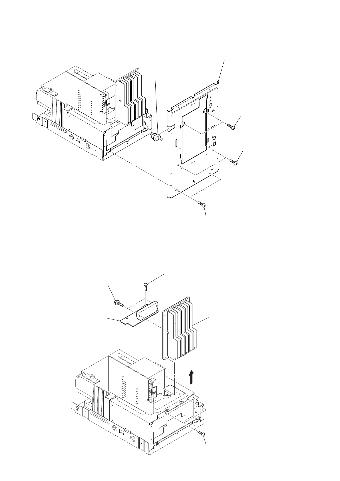
3-7. REAR PANEL
cord bushing (2104)
rear panel section
two
(
two
(
screws
+BVTP 3 × 10
screws
+BVTP 3 × 10
)
)
3-8. AMP BOARD
two
(transistor)
AMP board
screws
screw
(
+BVTP 3 × 10
two
(
)
screws
+BVTP 3 × 10
heat sink assy
)
18
two
screws
(
+BVTP 3 × 10
)
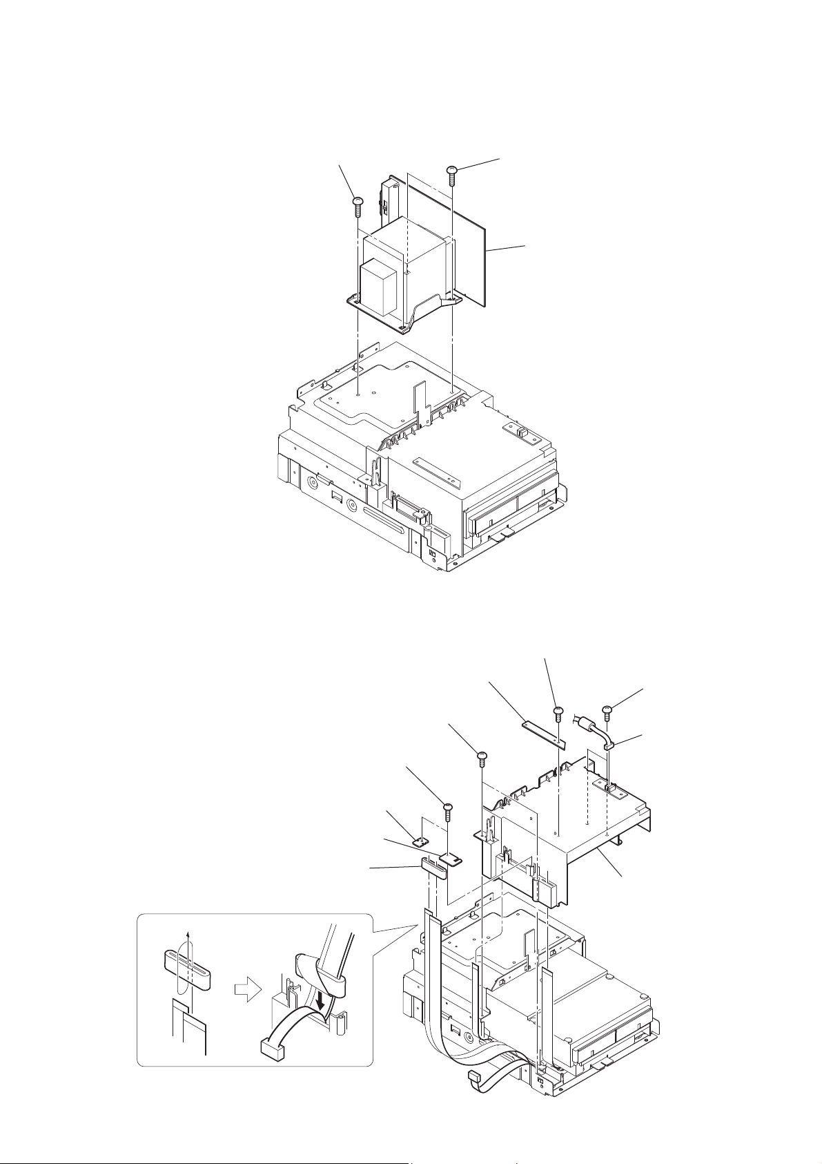
3-9. PT BOARD
two
(
+BVTP 4 × 6
screws
HCD-GZR5D
two
)
(
+BVTP 4 × 6
PT board
screws
)
3-10. COVER (CDM)
two screws
(+BVTP 2.6 × 8)
F HOLD B board
F HOLD A board
ferrite core
FFC HOLD board
two
screws
(+BV 3 (3-CR))
screw
(+BV 3 (3-CR))
two
(+BV 3 (3-CR))
CN824 (3P)
cover (CDM)
screws
19
HCD-GZR5D
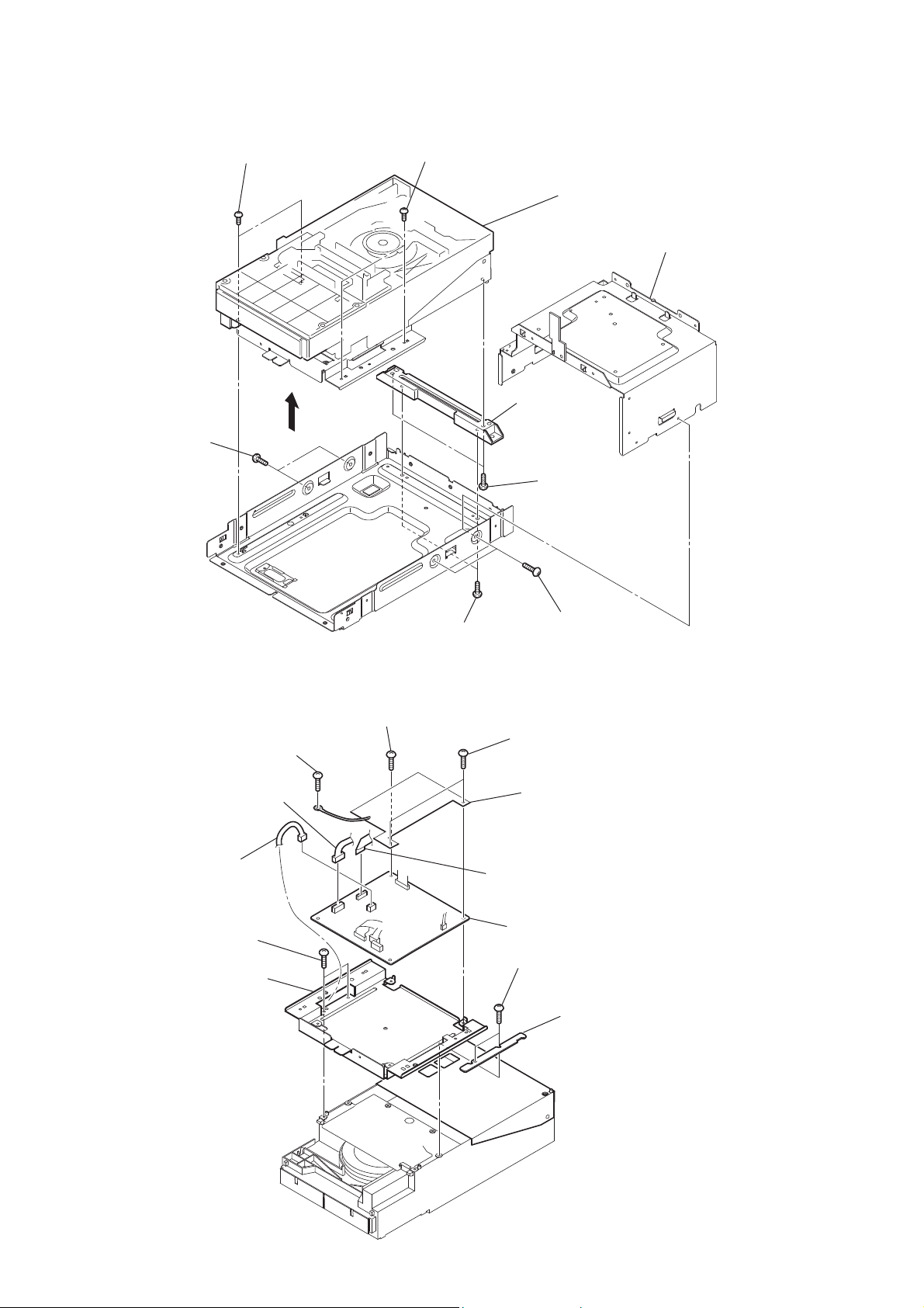
3-11. DVD MECHANISM SECTION
two
screws
(+BV 3 (3-CR))
two
screw
(
+BVTP 3 × 10
)
two
screws
(+BV 3 (3-CR))
bracket (CDM)
two
(
+BVTP 3 × 10
DVD mechanism section
bracket (PT)
screw
)
3-12. DMB18 BOARD
CN111 (3P)
RB two
(
+BVTP 3 × 10
RT bracket (PWB DVD)
screws
CN201 (6P)
screw
(+BV 3 (3-CR))
)
two
(
screw
(+BV 3 (3-CR))
two
screw
+BVTP 3 × 10
screws
two
(+BV 3 (3-CR))
copper leaf sheet (DMB)
wire (flat type) (24 core)
(CN101)
DMB18 board
two
+BVTP 3 × 10
(
screw
(
+BVTP 3 × 10
)
screws
WIRE PROTECT board
)
)
20
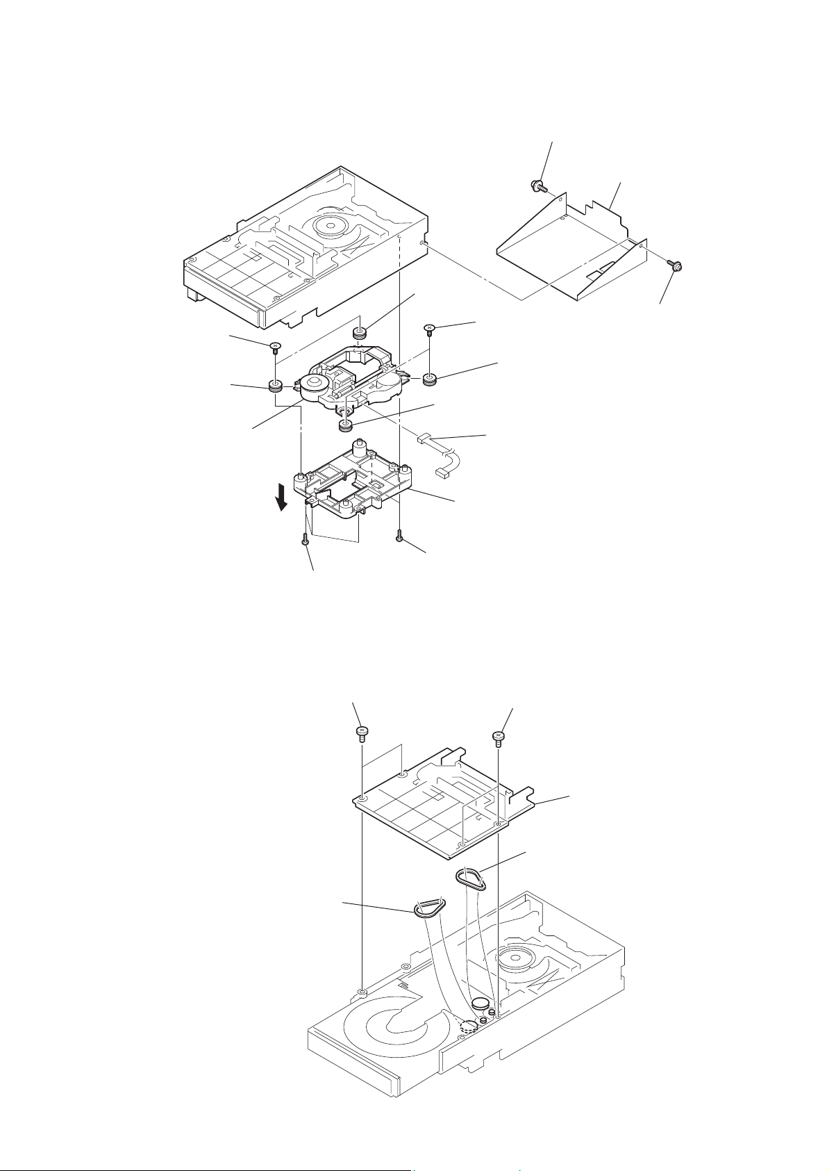
3-13. OPTRICAL PICK-UP
HCD-GZR5D
two
screws
(insulator)
RB insulator
RG optical pick-up
RT insulator
insulator
RH bracket (BU)
two
screws
(insulator)
insulator
RE cord
floating
(+PTPWHM 2.6)
screw
sheet (bottom)
floating
(+PTPWHM 2.6)
screw
3-14. BELT (DLM3A)
three
(
belt (DLM3A)
screws
+BTP 2.6 × 8
two screws
two
screws
(
+BTP 2.6 × 8
)
)
two screws
cover
belt (DLM3A)
21
HCD-GZR5D
3-15. MECHANISM DECK
Open the cassette box.
four screws
(
+BVTP 2.6 × 8
)
bracket (DECK)
3-16. BELT (MAIN), BELT (R/F)
belt (MAIN)
mechanical deck
connector
(CN501)
DECK board
two screws
(
+BVTP 3 × 6
)
22
belt (R/F)

SECTION 4
TEST MODE
HCD-GZR5D
[COLD RESET]
• The cold reset clears all data including preset data stored in the
RAM to initial conditions. Execute this mode when returning
the set to the customer.
Procedure:
1. Press the [
2. Press [DSGX] button, [DISC 1] button and [
simultaneously.
3. The message “RESET” appears on the LCD display. Then,
the LCD display becomes blank for a while, and the system is
reset.
[PANEL TEST MODE]
• This mode is used to check the LCD display, LEDs,
keys, VOLUME jog and OPERATION DIAL jog, model,
destination, software version and VACS level.
Procedure:
1. Press [x] button, [DISPLAY] button and [X] button
simultaneously.
2. All LEDs and segments in LCD display are lighted up. All
LEDs are lighted up.
3. When you want to enter to the software version dispaly mode,
press [FUNCTION] button. The model information appears
on the fl uorescent indicator tube. “G0012B0108” is shown.
Press [FUNCTION] button again to view the information.
4. Each time [DSGX] button is pressed, the display changes
from the destination information display.
5. To release from this mode, press [x] button, [DISPLAY]
button and [X] button simultaneously.
] button to turn on the system.
?/1
?/1
] button
[DVD SHIP MODE]
• This mode can run the DVD sled motor optionally. Use this
mode, for instance, when cleaning the optical pick-up.
Procedure:
1. Press the [
2. Press the [FUNCTION] button to select DVD function.
3. Press two buttons of [N] and [
4. Set to the DVD ship mode. (chucking on)
5. After blink “STANDBY”, “LOCK” is displayed, disconnect
the AC plug.
[DVD SHIP AND COLD RESET]
Procedure:
1. Press the [
2. Press the [FUNCTION] button to select DVD function.
3. Press three buttons of [FUNCTION], [DISC 2] and [
simultaneously.
4. After blink “STANDBY”, “RESET” is displayed, disconnect
the AC plug.
[DVD SLOT LOCK]
• This mode is for the antitheft of DVD disc in shop. (not for
transport)
Procedure:
1. Press the [
2. Press the [FUNCTION] button to select DVD function.
3. Insert a disc.
4. While pressing the [x] button, press the [Z] button for more
5 seconds.
5. The message “LOCKED” is displayed and the disc slot is
locked. (Even if exiting from this mode, the disc slot is still
locked)
6. If press the [Z] button to eject the disc, the message
“LOCKED” is displayed and can not eject the disc.
7. To release this lock, while pressing the [x] button, press the
[Z] button for 5 seconds again.
8. The message “UNLOCKED” is displayed and the disc slot is
unlocked.
] button to turn the power on.
?/1
?/1
] button to turn the power on.
?/1
] button to turn the power on.
?/1
] simultaneously.
?/1
]
[DVD COLOR SYSTEM]
• This mode let you change the color system of the video
output from PAL to NTSC or vice-versa. This mode is not
available for Latin American and Russian models.
Procedure:
1. Press [
2. Select DVD function.
3. Press [
4. After pressing the [DISPLAY] button, press [X] button
and [
automatically.
The message “COLOR PAL” or “COLOR NTSC” appears on
the LCD display.
] button to turn on the system.
?/1
] button again to turn off the system.
?/1
] button simultaneously. The system will turn on
?/1
23
HCD-GZR5D
[TUNER STEP CHANGE]
• The step interval of AM channels can be toggled between 9
kHz and 10 kHz. This mode is not available for Saudi Arabia
and Russia models.
Procedure:
1. Press [
] button to turn on the system.
?/1
2. Press [FUNCTION] button repeatedly to select the “AM”.
3. Press [
4. After pressing the [DISPLAY] button, press [TUNING +
y
] button to turn off the system.
?/1
] button and [
] button simultaneously. The system will
?/1
M
turn on automatically. The message “AM 9K STEP” or “AM
10K STEP” appears on the LCD display and thus the channel
step is changed.
[DVD SERVICE MODE]
• This mode let you make diagnosis and adjustment easily by
using the remote commander and the TV. The instructions,
diagnostic results, etc. are given on the on-screen display.
• TEST DISC LIST
Be sure to use the DVD disc that matches the signal standards
of your region.
• CD
YEDS-18 (Part No.: 3-702-101-01)
PATD-012 (Part No.: 4-225-203-01)
• DVD SL (Single Layer)
NTSC : HLX-503 (Part No.: J-6090-069-A)
HLX-504 (Part No.: J-6090-088-A)
PAL : HLX-506 (Part No.: J-6090-077-A)
• DVD DL (Dual Layer)
NTSC : HLX-501 (Part No.: J-6090-071-A)
HLX-505 (Part No.: J-6090-089-A)
PAL : HLX-507 (Part No.: J-6090-078-A)
• Procedure to enter to DVD Service Mode:
1. Press [
] button to turn on the system.
?/1
2. Select DVD function.
3. Press [x] button and [Z] button simultaneously and then turn
the [VOLUME] knob clockwise.
4. The message “SERVICE IN” appears on the LCD display and
the Top Menu of Remocon Diagnosis Menu appears on the
on-screen display on the TV. The model name, main unit’s
micom version information (IF-con) and DVD fi rmware
version information (Syscon) are displayed at the bottom of
the on-screen display.
Remocon Diagnosis Menu
0. External Chip Check
1. Servo Parameter Check
2. Drive Manual Operation
3. Emergency History
4. Version Information
Model Name : ESLOD_
IF-con : V
Syscon : Ver.
**
er. 01.01 (0000)
1.310
5. To execute each function, press its number by using numeric
button on the remote commander.
6. To release from this mode, press [
] button to turn off the
?/1
system.
• Execute IOP Measurement
In order to execute IOP measurement, the following standard
procedures must be followed.
1. From the Top Menu of Remocon Diagnosis Menu, select “2.
Drive Manual Operation” by pressing the [2] button on the
remote commander. The following screen appears on the onscreen display.
Drive Manual Operation
1. Servo Control
2. T rack/Layer Jump
3. Manual Adjustment
4. Mecha test Mode
5. MIRR time Adjust
0. Return to Top Menu
2. Select “3. Manual Adjustment” by pressing the [3] button on
the remote commander. The following screen appears on the
on-screen display.
Manual Adjust
1. Track Balance Adjust:
2. T rack Gain Adjust:
3. Focus Balance Adjust:
4. Focus Gain Adjust:
5. Eg Boost Adjust:
6. Iop:
7. TR V. Level:
8. S curve(FE) Level:
9. RFL(PI) Level:
0. MIRR Time:
0P Change Value
RETURN Return to previous menu
3. Select “6. Iop:” by pressing [6] button on the remote
commander.
4. Wait until a hexadecimal number appears in the on-screen
display as below:
Manual Adjust
1. Track Balance Adjust:
2. T rack Gain Adjust:
3. Focus Balance Adjust:
4. Focus Gain Adjust:
5. Eg Boost Adjust:
6. Iop. ED:
7. TR V. Level:
8. S curve(FE) Level:
9. RFL(PI) Level:
0. MIRR Time:
0P Change Value
RETURN Return to previous menu
24
5. Convert data from hexadecimal to decimal by using
conversion table.
6. Please fi nd the label on the rear of the BU (Base Unit).
The default IOP value is written in the label.
HCD-GZR5D
7. Subtract between these two values.
8. If the remainder is smaller than 93 (decimal), then it is
OK. However if the value is higher than 93, then the BU is
defective and need to be change.
9. Press [RETURN] button on the remote commander to return
to previous menu.
10. Press [0] button on the remote commander to return to the
Top Menu of Remocon Diagnosis Menu.
11. Press [
] button to turn off the system.
?/1
• Check Emergency History
To check the emergency history, please follow the following
procedure.
1. From the Top Menu of Remocon Diagnosis Menu, select “3.
Emergency History” by pressing the [3] button on the remote
commander. The following screen appears on the on-screen
display.
Emg. History Check
Laser Hours CD 999h 59min
1. 01 05 04 04
00 00 00 00 00 00 23 45
2. 02 02 01 01 00 A9 4B 00
00 00 00 00 00 00 23 45
Next Next Page Prev Prev Page
O Return to Top Menu
DVD 999h 59min
00 92 46 00
2. You can check the total time when the laser is turned on
during playback of DVD and CD from the above menu. The
maximum time, which can be displayed are 999h 59min.
3. You can check the error code of latest 10 emergency history
from the above menu. To view the previous or next page
of emergency history, press [.] or [>] on the remote
commander. The error code consists of
• Error Code
Example of Error code
1. 01 05 04 04 00 92 46 00
00 00 00 00 00 00 23 45
The meaning of error code is as below:
01: Communication error (No reply from syscon)
02: Syscon hung up
03: Power OFF request when syscon hung up
19: Thermal shutdown
24: MoveSledHome error
25: Mechanical move error (5 Changer)
26: Mechanical move stack error
30: DC motor adjustment error
31: DPD offset adjustment error
32: TE balance adjustment error
33: TE sensor adjustment error
34: TE loop gain adjustment error
35: FE loop gain adjustment error
36: Bad jitter after adjustment
40: Focus NG
42: Focus layer jump NG
52: Open kick spindle error
51: Spindle stop error
60: Focus on error
61: Seek fail error
62: Read Q data/ID error
70: Lead in data read fail
71: TOC read time out (CD)
80: Can’t buffering
81: Unknown media type
• Parameter of error code
This is the detail of error code.
Example of Error code
1. 01 05 04 04 00 92 46 00
00 00 00 00 00 00 23 45
• Time of error code
This is the laser time when an error occurred.
Example of Error code
1. 01 05 04 04 00 92 46 00
00 00 00 00 00 00 23 45
25

HCD-GZR5D
To clear the Laser Hour
Press [DISPLAY] button and then press [CLEAR] button. The
data for both CD and DVD data are reset.
Emg. History Check
Laser Hours CD 0h 0min
1. 01 05 04 04
00 00 00 00 00 00 23 45
2. 02 02 01 01 00 A9 4B 00
00 00 00 00 00 00 23 45
Next Next Page Prev Prev Page
O Return to Top Menu
DVD 0h 0min
00 92 46 00
To clear the Emergency History
Press [DVD TOP MENU] button and then press [CLEAR] button.
The error code for all emergency history would be reset.
Emg. History Check
Laser Hours CD 999h 59min
1. 00 00 00 00
00 00 00 00 00 00 00 00
2. 00 00 00 00 00 00 00 00
00 00 00 00 00 00 00 00
Next Next Page Prev Prev Page
O Return to Top Menu
DVD 999h 59min
00 00 00 00
To return to the Top Menu of Remocon Diagnosis Menu
Press [0] button on the remote commander.
• Check Version Information
To check the version information, please follow the following
procedure.
1. From the Top Menu of Remocon Diagnosis Menu, select “4.
Version Information” by pressing the [4] button on the remote
commander. The following screen appears on the on-screen
display.
Emg. History Check
Laser Hours CD 999h 59min
DVD 999h 59min
Initialize setup data...
Next Next Page Prev Prev Page
O Return to Top Menu
To return to the Top Menu of Remocon Diagnosis Menu,
press [0] on the remote commander.
To clear the Initialize Setup Data
Press [DVD/TUNER MENU] button and then press [CLEAR]
button on the remote commander.
Version information
Firm (Main) : Ver. xxxxx
Firm (Sub) : xxxxx
RISC : xxxxx
8032 : xxxxx
Audio DSP : xxxxx
Servo DSP : xxxxx
O Return to Top Menu
26
SECTION 5
MECHANICAL ADJUSTMENTS
HCD-GZR5D
SECTION 6
ELECTRICAL ADJUSTMENTS
• Precaution
1. Clean the following parts with a denatured alcohol-moistened
swab:
record/playback heads pinch rollers
erase head rubber belts
capstan idlers
2. Demagnetize the record/playback head with a head
demagnetizer. (Do not bring the head magnetizer close to the
erase head.)
3. Do not use a magnetized screwdriver for the adjustments.
4. After the adjustments, apply suitable locking compound to
the parts adjusted.
5. The adjustments should be performed with the rated power
supply voltage unless otherwise noted.
• Torque Measurement
Mode Torque meter Meter reading
FWD CQ-102AS
FWD
back tension
FF CQ-201AS
REW CQ-201B
CQ-102C
2.0 – 8.0 mN • m
(20 to 80 g • cm)
(0.28 – 1.12 oz • inch)
0.15 – 0.6 mN • m
(1.5 to 6 g • cm)
(0.021 – 0.083 oz • inch)
5 – 17.7 mN • m
(50 to 177 g • cm)
(0.7 – 2.48 oz • inch)
5 –17.7 mN • m
(50 to 177 g • cm)
(0.7 – 2.48 oz • inch)
• Tape Tension Measurement
Mode Torque meter Meter reading
FWD CQ-403A
more than 80 g
(more than 2.82 oz)
DECK SECTION
0 dB = 0.775V
1. Demagnetize the record/playback head with a head
demagnetizer.
2. Do not use a magnetized screwdriver for the adjustments.
• Test Tape
Tape Signal Used for
P-4-A063 6.3 kHz, – 10 dB Azimuth Adjustment
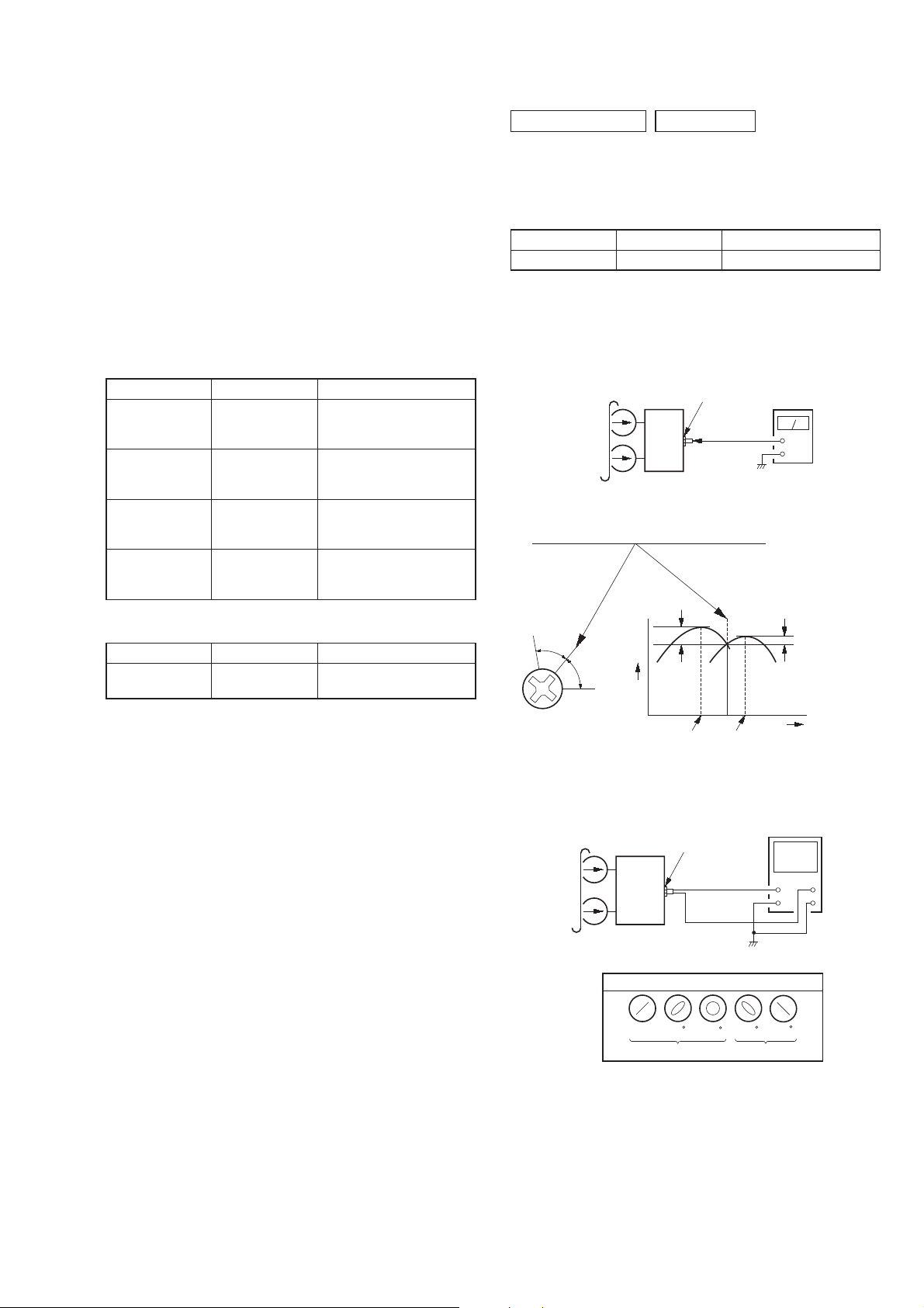
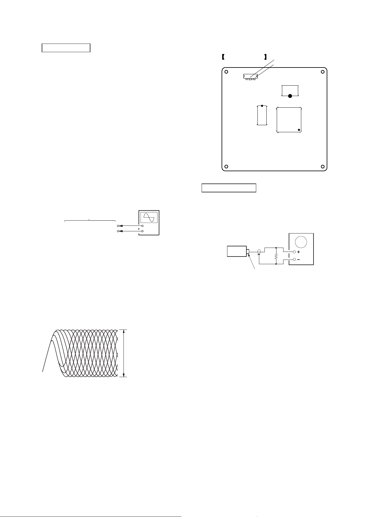
RECORD/PLAYBACK HEAD AZIMUTH ADJUSTMENT
Procedure:
1. Mode: Playback
test tape
P-4-A063
(6.3 kHz, -10 dB)
set
JACK board
PHONES jack
(J252)
level meter
+
–
2. Turn the adjustment screw and check output peaks. If the peaks
do not match for L-CH and R-CH, turn the adjustment screw
so that outputs match within 1dB of peak.
Output
level
within
1dB
L-CH
peak
R-CH
peak
within
1dB
Screw
position
L-CH
peak
Screw
position
R-CH
peak
3. Mode: Playback
test tape
P-4-A063
(6.3 kHz, -10 dB)
in phase
JACK board
PHONES jack
(J252)
set
waveform of oscilloscope
45 90 135
good
wrong
oscilloscope
V
H
180
4. After the adjustments, apply suitable locking compound to the
pats adjusted.
27
HCD-GZR5D
Adjustment Location: Record/Playback/Erase Head
TUNER SECTION
[FM TUNE LEVEL CHECK]
signal
generator
OUTPUT
(75 7)
Procedure:
1. Turn on the set.
2. Input the following signal from signal generator to FM
antenna input directly.
Carrier frequency: A = 87.5 MHz, B = 98 MHz, C = 108 MHz
Deviation : 75 kHz
Modulation : 1 kHz
ANT input : 35 dBu (EMF)
Note: Use 75 ohm coaxial cable to connect signal generator and
the set.
You cannot use video cable for checking.
Use signal generator whose output impedance is 75 ohm.
3. Set to FM tuner function and tune A, B and C signals.
4. Confi rm “TUNED” is lit on the display for A, B and C sig-
nals.
set
When the selected station signal is received in good condition,
“TUNED” is displayed.
28
HCD-GZR5D
DVD SECTION
When the optical pick-up assy is replaced, perform the “Execute
IOP Measurement”.
Execute IOP Measurement (See page 23)
[TEST DISC LIST]
Be sure to use the DVD disc that matches the signal standards of
your region.
• CD
YEDS-18 (Part No.: 3-702-101-01)
PATD-012 (Part No.: 4-225-203-01)
• DVD SL (Single Layer)
NTSC : HLX-503 (Part No.: J-6090-069-A)
HLX-504 (Part No.: J-6090-088-A)
PAL : HLX-506 (Part No.: J-6090-077-A)
• DVD DL (Dual Layer)
NTSC : HLX-501 (Part No.: J-6090-071-A)
HLX-505 (Part No.: J-6090-089-A)
PAL : HLX-507 (Part No.: J-6090-078-A)
[RFMON Level Check]
Connection:
oscilloscope
DMB18 board
CN105 pin (RFMON)
CN105 pin (GND)
+
–
Checking Location: DMB18 board (Side A)
DMB18 BOARD
(SIDE A)
CN105
1
6
CN105 pin (GND)
CN105 pin (RFMON)
IC101
IC104
IC102
VIDEO SECTION
Video Level Check (MAIN BOARD)
Purpose
This adjustment is made to satisfy the NTSC standard, and if not
adjusted correctly, the brightness will be too large or small.
oscilloscope
Procedure:
1. Connect an oscilloscope to CN105 pin 6 (RFMON) and CN105
pin 3 (GND) on the DMB18 board.
2. Turn the power on.
3. Set the test disc (refer to the TEST DISC LIST) on the tray and
press [N] button to playback.
4. Confi rm that oscilloscope waveform is clear and check
RFMON signal level is correct or not.
Note: A clear RFMON signal waveform means that the shape “◊”
can be clearly distinguished at the center of the waveform.
RFMON signal waveform
VOLT/DIV: 200 mV
TIME/DIV: 500 ns
level:
0.58 ± 1.23 Vp-p
0.57 ± 1.1 Vp-p
(DVD)
(CD)
75 7
set
J701
VIDEO OUTPUT
Procedure:
1. Connect oscilloscope to VIDEO output.
2. Load a DVD reference disc playback.
3. Check the video signal level is 1.00 ± 0.07Vp-p.
29

HCD-GZR5D
MEMO
30
 Loading...