

Sony HCD-DZ820KW Service Manual

HCD-DZ820KW
SERVICE MANUAL
Ver. 1.1 2006.09
HCD-DZ820KW is the amplifier, DVD/CD and
tuner section in DAV-DZ820KW.
This system incorporates with Dolby*1 Digital and Dolby Pro Logic (II)
adaptive matrix surround decoder and the DTS*2 Digital Surround
System.
*1 Manufactured under license from Dolby Laboratories.
“Dolby,” “Pro Logic,” and the double-D symbol are trademarks of
Dolby Laboratories.
*2 Manufactured under license from Digital Theater Systems, Inc.
“DTS” and “DTS Digital Surround” are trademarks of Digital
Theater Systems, Inc.
Russian Model
E Model
Australian Model
Model Name Using Similar Mechanism HCD-DZ110
Mechanism T ype CDM85-DVBU102
Optical Pick-up Name
KHM-310CAA/C2RP
Amplifier section
Asian, Australian, and Middle Eastern models:
Stereo mode (rated) 108 W + 108 W (3 ohms at
1 kHz, 1 % THD)
Surround mode (reference) RMS output power, 10 %
THD
Front: 142 W + 142 W
(with SS-TS55)
Center*: 142 W
(with SS-CT52)
Surround*: 142 W + 142
W** (3 ohms)
Subwoofer*: 180 W
(with SS-WS52B)
Other models:
Stereo mode (rated) 108 W + 108 W (3 ohms at
1 kHz, 1 % THD)
Surround mode (reference) RMS output power, 10 %
THD
Front: 143 W + 143 W
(with SS-TS55)
Center*: 143 W
(with SS-CT52)
Surround*: 143 W + 143
W** (3 ohms)
Subwoofer*: 285 W
(with SS-WS52B)
SPECIFICATIONS
*Depending on the sound field settings and the source,
there may be no sound output.
** When connecting the surround speakers to the system
by the speaker cords.
Inputs (Analog)
TV/VCR 1 (AUDIO IN) Sensitivity: 450/250 mV
AUDIO IN/MIC 1 Sensitivity:
AUDIO IN 250/125 mV/
MIC 1 1 mV
MIC 2 Sensitivity: 1 mV
Inputs (Digital)
TV/VCR1 (OPTICAL IN)/TV/VCR2 (COAXIAL IN)
impedance: –/75 ohms
Super Audio CD/DVD system
Laser Semiconductor laser
(Super Audio CD/DVD:
λ = 650 nm)
(CD: λ = 790 nm)
Emission duration:
continuous
Signal format system NTSC/PAL
Tuner section
System PLL quartz-locked digital
synthesizer system
FM tuner section
Tuning range 87.5-108.0 MHz (50 kHz
step)
Antenna (aerial) FM wire antenna (aerial)
Antenna (aerial) terminals 75 ohms, unbalanced
Intermediate frequency 10.7 MHz
AM tuner section
Tuning range
Middle Eastern and Russian models:
531 - 1,602 kHz (with the
interval set at 9 kHz)
Asian models: 531 - 1,602 kHz (with the
interval set at 9 kHz)
530 - 1,710 kHz (with the
interval set at 10 kHz)
Antenna (aerial) AM loop an tenna (aerial)
Intermediate frequency 450 kHz
9-887-246-02
2006I16-1
© 2006.09
SUPER AUDIO CD/DVD RECEIVER
Sony Corporation
Home Audio Division
Published by Sony Techno Create Corporation
HCD-DZ820KW
Video section
Outputs VIDEO: 1 Vp-p 75 ohms
S VIDEO:
Y: 1 Vp-p 75 ohms
C: 0.286 Vp-p 75 ohms
COMPONENT:
Y: 1 Vp-p 75 ohms
PB/CB, PR/CR: 0.7 Vp-p
75 ohms
HDMI OUT: Type A (19
pin)
Inputs TV/VCR1: 1 Vp-p
75 ohms
General
Power requirements
220 - 240 V AC, 50/60 Hz
Power consumption On: 170 W
Standby: 0.3 W (at the
Power Saving Mode)
Dimensions (approx.) 430 × 55 × 390 mm
(w/h/d) incl. projecting
parts
Mass (approx.) 4.0 kg
Design and specifications are subject to change
without notice.
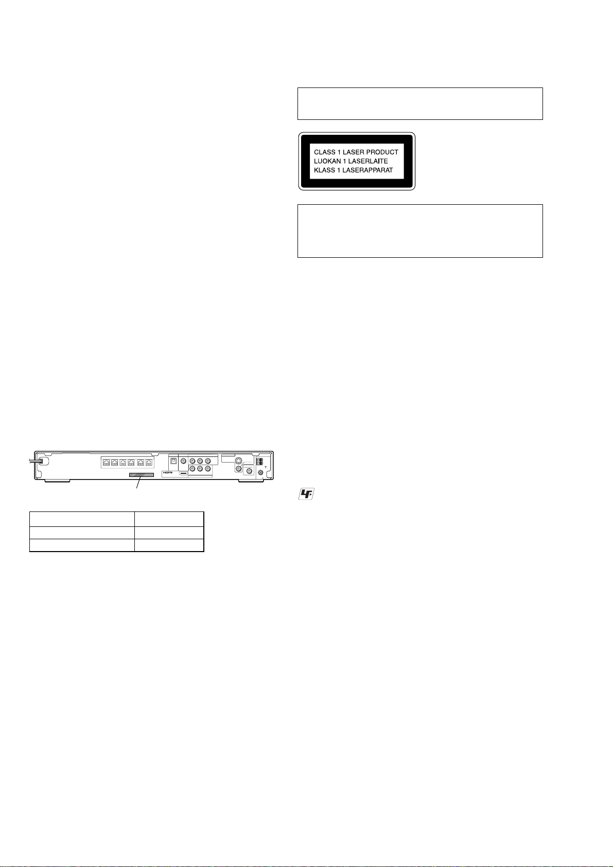
Laser component in this product is capable of emitting radiation
exceeding the limit for Class 1.
This appliance is classified as
a CLASS 1 LASER product.
This marking is located on
the rear or bottom exterior.
CAUTION
Use of controls or adjustments or performance of procedures
other than those specified herein may result in hazardous radiation
exposure.
Notes on chip component replacement
• Never reuse a disconnected chip component.
• Notice that the minus side of a tantalum capacitor may be
damaged by heat.
Flexible Circuit Board Repairing
• Keep the temperature of the soldering iron around 270 °C
during repairing.
• Do not touch the soldering iron on the same conductor of the
circuit board (within 3 times).
• Be careful not to apply force on the conductor when soldering
or unsoldering.
MODEL IDENTIFICATION
– Rear Panel –
TV/VCR1 TV/VCR2
SPEAKER
FRONT R FRONT L SUR R SUR LCENTER WOOFER
Parts No.
Model Part No.
E3 model 2-661-238-2[]
EXCEPT E3 models 2-661-238-7[]
•Abbreviation
E3 : 240V AC area in E model
DIGITAL IN
OPTICAL
OUT
(DVD ONLY)
DIGITAL IN
COAXIAL
COMPONENT VIDEO OUT
YPB/CBPR/C
RLAUDIO IN VIDEO IN
TV/VCR1
UNLEADED SOLDER
Boards requiring use of unleaded solder are printed with the lead-
MONITOR OUT
(DVD ONLY)
(DVD ONLY)
V
S VIDEO
VIDEO
AM
DIR-T1
COAXIAL
FM
75
R
free mark (LF) indicating the solder contains no lead.
(Caution: Some printed circuit boards may not come printed with
the lead free mark due to their particular size)
: LEAD FREE MARK
Unleaded solder has the following characteristics.
• Unleaded solder melts at a temperature about 40 °C higher
than ordinary solder.
Ordinary soldering irons can be used but the iron tip has to be
applied to the solder joint for a slightly longer time.
Soldering irons using a temperature regulator should be set to
about 350 °C.
Caution: The printed pattern (copper foil) may peel away if
the heated tip is applied for too long, so be careful!
• Strong viscosity
Unleaded solder is more viscou-s (sticky, less prone to flow)
than ordinary solder so use caution not to let solder bridges
occur such as on IC pins, etc.
• Usable with ordinary solder
It is best to use only unleaded solder but unleaded solder may
also be added to ordinary solder.
SAFETY-RELATED COMPONENT WARNING!!
COMPONENTS IDENTIFIED BY MARK 0 OR DOTTED LINE
WITH MARK 0 ON THE SCHEMATIC DIAGRAMS AND IN
THE PARTS LIST ARE CRITICAL TO SAFE OPERATION.
REPLACE THESE COMPONENTS WITH SONY PARTS WHOSE
PART NUMBERS APPEAR AS SHOWN IN THIS MANUAL OR
IN SUPPLEMENTS PUBLISHED BY SONY.
2

TABLE OF CONTENTS
HCD-DZ820KW
1. SERVICING NOTE ................................................... 4
2. GENERAL ................................................................... 9
3. DISASSEMBLY
3-1. Disassembly Flow ........................................................... 12
3-2. Case, Front Panel Assy .................................................... 13
3-3. FL Board.......................................................................... 14
3-4. JACK Board, SW Board .................................................. 14
3-5. IO-S TERMINAL Board, SPEAKER Board .................. 15
3-6. MAIN Board.................................................................... 15
3-7. DMB12 Board ................................................................. 16
3-8. DIAT-TX Board ............................................................... 16
3-9. DC Fan, Tuner Unit ......................................................... 17
3-10. POWER Board ................................................................ 17
3-11. DVD Mechanism Deck (CDM85-DVBU102) ................ 18
3-12. Tray .................................................................................. 18
3-13. Belt, MS-203 Board ........................................................ 19
3-14. Optical Pick-up (KHM-310CAA) ................................... 20
4. TEST MODE ............................................................... 21
5. ELECTRICAL ADJUSTMENT ............................. 25
6. DIAGRAMS
6-1. Block Diagram – RF Section –....................................... 28
6-2. Block Diagram – AMP Section – ................................... 29
6-3. Block Diagram – AUDIO Section – ............................... 30
6-4. Block Diagram – VIDEO Section – ............................... 31
6-5. Block Diagram – DIAT Section – .................................. 32
6-6. Block Diagram – POWER Section –.............................. 33
6-7. Printed Wiring Board – DMB12 Board (Side A) – ........ 34
6-8. Printed Wiring Board – DMB12 Board (Side B) – ........ 35
6-9. Schematic Diagram – DMB12 Board (1/7) –................. 36
6-10. Schematic Diagram – DMB12 Board (2/7) –................. 37
6-11. Schematic Diagram – DMB12 Board (3/7) –................. 38
6-12. Schematic Diagram – DMB12 Board (4/7) –................. 39
6-13. Schematic Diagram – DMB12 Board (5/7) –................. 40
6-14. Schematic Diagram – DMB12 Board (6/7) –................. 41
6-15. Schematic Diagram – DMB12 Board (7/7) –................. 42
6-16. Printed Wiring Board – MAIN Board (Side A) –........... 43
6-17. Printed Wiring Board – MAIN Board (Side B) – ........... 44
6-18. Schematic Diagram – MAIN Board (1/8) – ................... 45
6-19. Schematic Diagram – MAIN Board (2/8) – ................... 46
6-20. Schematic Diagram – MAIN Board (3/8) – ................... 47
6-21. Schematic Diagram – MAIN Board (4/8) – ................... 48
6-22. Schematic Diagram – MAIN Board (5/8) – ................... 49
6-23. Schematic Diagram – MAIN Board (6/8) – ................... 50
6-24. Schematic Diagram – MAIN Board (7/8) – ................... 51
6-25. Schematic Diagram – MAIN Board (8/8) – ................... 52
6-26. Printed W iring Board
– IO-S TERMINAL Board (Side A) –............................. 53
6-27. Printed W iring Board
– IO-S TERMINAL Board (Side B) –............................. 54
6-28. Schematic Diagram – IO-S TERMINAL Board – ......... 55
6-29. Printed Wiring Boards – PANEL Section –.................... 56
6-30. Schematic Diagram – PANEL Section – ........................ 57
6-31. Printed Wiring Board – SPEAKER Board – .................. 58
6-32. Schematic Diagram – SPEAKER Board –..................... 58
6-33. Printed Wiring Board – DIAT-TX Board – .................... 59
6-34. Schematic Diagram – DIAT-TX Board – ....................... 60
6-35. Printed Wiring Board – MS-203 Board – ....................... 61
6-36. Schematic Diagram – MS-203 Board – ......................... 61
6-37. Printed Wiring Board – POWER Board – ...................... 62
6-38. Schematic Diagram – POWER Board – ......................... 63
7. EXPLODED VIEWS
7-1. Overall Section ................................................................ 76
7-2. Front Panel Section ......................................................... 77
7-3. Chassis Section................................................................ 78
7-4. DVD Mechanism Deck Section (CDM85-DVBU102) ... 79
8. ELECTRICAL PARTS LIST .................................. 80
3

HCD-DZ820KW
SECTION 1
SERVICING NOTE
NOTES ON HANDLING THE OPTICAL PICK-UP BLOCK
OR BASE UNIT
The laser diode in the optical pick-up block may suffer electrostatic
break-down because of the potential difference generated by the
charged electrostatic load, etc. on clothing and the human body.
During repair, pay attention to electrostatic break-down and also
use the procedure in the printed matter which is included in the
repair parts.
The flexible board is easily damaged and should be handled with
care.
NOTES ON LASER DIODE EMISSION CHECK
The laser beam on this model is concentrated so as to be focused on
the disc reflective surface by the objective lens in the optical pickup block. Therefore, when checking the laser diode emission,
observe from more than 30 cm away from the objective lens.
LASER DIODE AND FOCUS SEARCH
1. Open the cover and turn POWER on with no disc inserted.
2. Confirm that the following operation is performed while
observing the objecting lens.
1) Confirm that laser beam is spread.
2) Up and down motion of the objective lens. (3 times)
DISC TRA Y LOCK
The disc tray lock function for the antitheft of an demonstration
disc in the store is equipped.
Setting Procedure :
1. Press the ?/1 button to turn the set on.
2. Press the [FUNCTION] button to set DVD function.
3. Insert a disc.
4. Press the
x button and the A button simultaneously for five
seconds.
5. The message “LOCKED” is displayed and the tray is locked.
Releasing Procedure :
1. Press the x button and the A button simultaneously for fiv e
seconds again.
2. The message “UNLOCKED” is displayed and the tray is
unlocked.
Note : When “LOCKED” is displayed, the tray lock is not released by
turning power on/off with the ?/1 button.
Self-diagnosis Function
(When letters/numbers appear in the
display)
When the self-diagnosis function is activated to
prevent the system from malfunctioning, a 5character service number (e.g., C 13 50) with a
combination of a letter and 4 digits appears on
the screen and the front panel display. In this
case, check the following table.
C:13:50
First 3
characters of
the service
number
C 13 The disc is dirty.
C 31 The disc is not inserted correctly.
E XX
(xx is a number)
When displaying the version
number on the screen
When you turn on the system, the version
number [VER.X.XX] (X is a number) may
appear on the screen. Although this is not a
malfunction and for Sony service use only,
normal system operation will not be possible.
Turn off the system, and then turn on the system
again to operate.
Cause and/or corrective action
,Clean the disc with a soft cloth
,Restart the system, then re-insert
the disc correctly.
To prevent a malfunction, the
system has performed the selfdiagnosis function.
,Contact your nearest Sony
dealer or local authorized Sony
service facility and give the 5character service number.
Example: E 61 10
Note on DMB12 board replacement
New part of EEP ROM (IC103, IC706) on the DMB12 board cannot be
used. Therefore, if the mounted DMB12 board (A-1166-695-A, A-1166728-A) is replaced, exchange new EEP ROM (IC103, IC706) with that used
before the replacement.
4
VER.X.XX

HOW TO OPEN THE DISC TABLE WHEN POWER SWITCH TURNS OFF
Insert a tapering driver into the aperture of the unit bottom, and slide
it in the direction of the arrow.
tapering driver
disc tray
Discharge the charged electricity in capacitors to prevent electric shock as follows
When disassembling the machine, be sure to discharge the charged electricity in the following capacitors.
Use a resistor of 800 ohms, 2 Watts for discharging the following capacitors.
HCD-DZ820KW
POWER board
C903 : 600V
C932, C933, C939, CN902 : 30V
MAIN board
CN3002 : 30 V
MAIN BOARD
(Parts face side)
*
Connect the specified resistor
between black and red leads
POWER BOARD
(Parts face side)
CN3002
BLACK
RED
CN902
C932
C933
C939
C903
5

HCD-DZ820KW
Fix the capacitors with adhesive agent as follows
Fixing the capacitors with adhesive agent is required by the safety regulation.
Be sure to fix the capacitors with adhesive agent when part or circuit board is replaced.
POWER BOARD
C910
C924 IC921
C930
PRECAUTION WHEN INSTALLING A NEW OP UNIT /
PRECAUTION BEFORE UNSOLDERING THE STATIC ELECTRICITY
PREVENTION SOLDER BRIDGE
When installing a new OP unit, be sure to connect the flexible printed circuit board first of all before removing the static
electricity prevention solder bridge by unsoldering. Remove the static electricity prevention solder bridge by unsoldering
after the flexible printed circuit board has already been connected.
(Do not remove nor unsolder the solder bridge as long as the OP unit is kept standalone.)
6

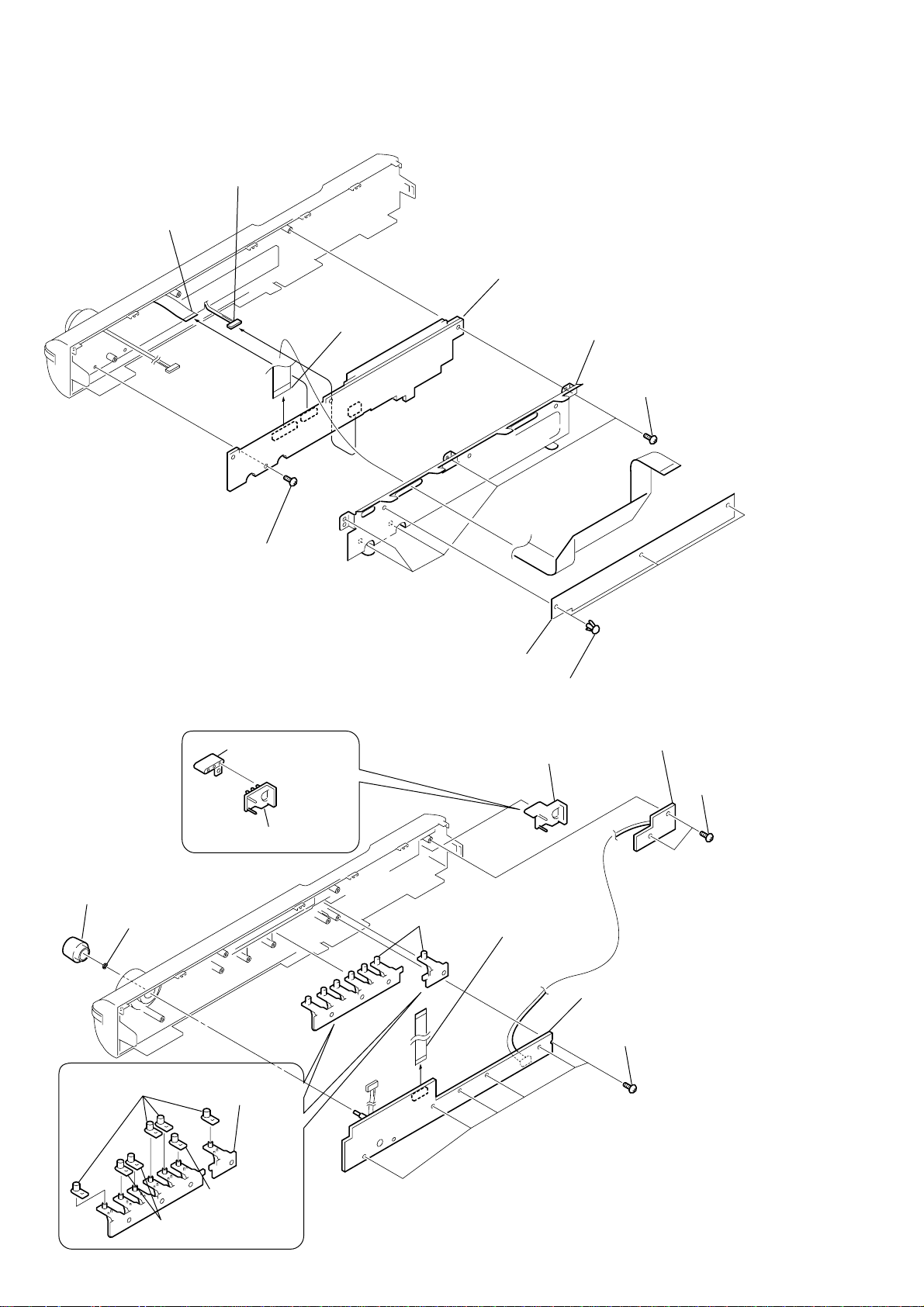
HCD-DZ820KW
JACK board
BUTTON BASE
(PLAY)
CAP (POWER)
wire (flat type)
13core (CNP802)
six screws (+BVTP 2.6)
two screws
(+BVTP 2.6)
BUTTON BASE (POWER)
SW board
CAP (PLAY)
CAP (AMS)
CAP (FUNC)
Precaution when replacing the CAP
Please apply the adhesive agent to the BUTTON BASE (PLAY) when replacing the CAP (PLAY) or CAP (FUNC) or CAP (AMS).
Please apply the adhesive agent to the BUTTON BASE (POWER) when replacing the CAP (POWER).
7

HCD-DZ820KW
• MAIN board service position
MAIN board
CN651
CN701
Extension cable
J-2501-242-A
(1mm/11pin/L300)
I/O SCART board
DIAT-TX board
CN801
DMB12 board
• DMB12 board service position
CN4501
Extension cable
J-2501-242-A
(1mm/11pin/L300)
insulation sheet
DMB12 board
CN4501
Extension cable
CN701
MAIN board
J-2501-242-A
(1mm/11pin/L300)
8

Front panel
SECTION 2
GENERAL
HCD-DZ820KW
This section is extracted
from instruction manual.
A "/1 (on/standby) (32)
B Front panel display (104)
C A (open/close) (32)
D Disc operation (32)
E FUNCTION (32)
Rear panel
SPEAKER
FRONT R FRONT L SUR R SUR LCENTER WOOFER
A SPEAKER jacks (15)
B TV/VCR 1 (DIGITAL IN OPTICAL) jack
(30)
C TV/VCR 2 (DIGITAL IN COAXIAL) jack
(30)
D COMPONENT VIDEO OUT jacks (26)
E MONITOR OUT (S VIDEO/VIDEO) jacks
(26)
F (remote sensor) (8)
G MIC 2 jack (68)
H VOLUME control (32)
I AUDIO IN/MIC 1/A.CAL MIC jack (34, 68)
J Disc tray (32)
TV/VCR1 TV/VCR2
DIGITAL IN
DIGITAL IN
COAXIAL
OPTICAL
OUT
(DVD ONLY)
COMPONENT VIDEO OUT
YPB/CBPR/C
RLAUDIO IN VIDEO IN
TV/VCR1
R
(DVD ONLY)
MONITOR OUT
S VIDEO
(DVD ONLY)
V
VIDEO
DIR-T1
COAXIAL
FM
AM
75
F AM terminal (15)
G COAXIAL FM 75Ω jack (15)
H DIR-T1 jack (15)
I TV/VCR 1 (AUDIO IN R/L, VIDEO IN)
jacks (30)
J HDMI OUT jack (26)
9
HCD-DZ820KW
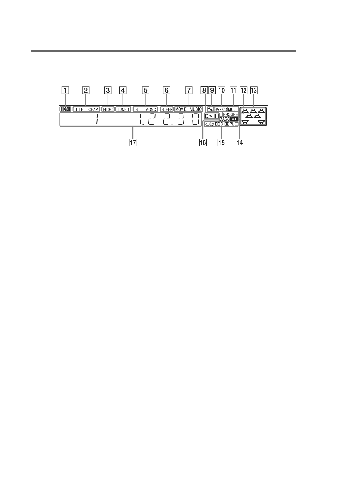
Front panel display
About the indications in the front panel display
A Lights up when the HDMI OUT jack is
correctly connected to HDCP (highbandwidth digital content protection)
compliant device with HDMI or DVI
(digital visual interface) input. (26)
B Lights up when the time information of
a title or chapter appears in the front
panel display. (DVD only) (49)
C Lights up when the color system is set
to NTSC. (Asian, Australian, and Middle
Eastern models only) (18)
D Lights up when a station is received.
(Radio only) (64)
E Monaural/Stereo effect (Radio only)
(64)
F Lights up when the sleep timer is set.
(72)
G Lights up when the music or movie
mode is selected. (35)
H Playing status (DVD function only)
I Lights up when the karaoke mode is
on. (68)
J Lights up when Super Audio CD/CD is
loaded.
K Lights up during MULTI channel
playback. (Super Audio CD only) (53)
L Lights up when the system outputs
progressive signals (DVD function
only). (28)
M Indicates the selected [SPEAKER
FORMATION]. (77)
N Lights up when Digital Cinema Sound
(DCS) is activated. (36)
O Current surround format (Except for
JPEG and Super Audio CD)
P Lights up when the DYNAMIC BASS is
selected. (72)
Q Displays system’s status such as
chapter, title, or track number, time
information, radio frequency, playing
status, sound field, etc.
10
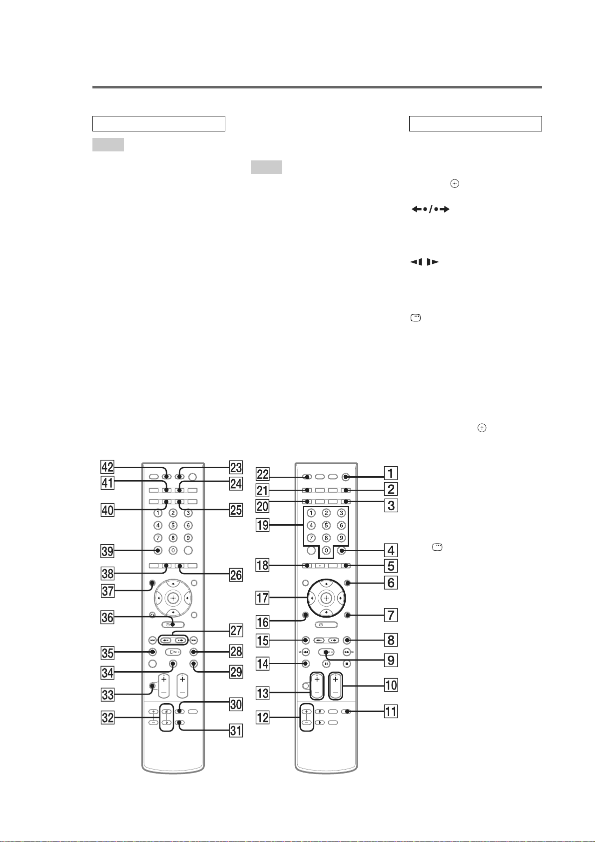
Remote control
HCD-DZ820KW
ALPHABETICAL ORDER
A – O
AMP MENU4) 7 (23, 34, 73,
111)
ANGLE 5 (52)
AUDIO
3)
ek (47)
CLEAR el (40, 64, 67, 81)
D.TUNING wh (64)
DISC SKIP
1)
qf (32)
DISPLAY 2 (49, 65)
DYNAMIC BASS 3 (72)
ECHO ea (69)
ENTER
2)
4 (20, 23, 34, 40, 63,
74)
FUNCTION +/–
3)
0 (28, 32, 33,
42, 63, 77)
KARAOKE MODE qa (68)
KARAOKE PON e; (70)
KEY CON #/b es (70)
MENU 6 (46, 63)
MIC VOL +/– qs (69)
MOVIE/MUSIC wg (35)
MUTING ed (32)
Number buttons
3)
ql (40, 64, 66,
74)
P – Z
PICTURE NAVI qk (41, 67)
PRESET +/– 8 qg (64)
PROGRESSIVE w; (28)
SA-CD/CD wf (53)
SLEEP ra (72)
SOUND FIELD r; (36)
SUBTITLE wh (52)
THEATRE SYNC wd (68)
TOP MENU ej (46)
TUNING +/– wk eg (63)
TV ws (66)
TV CH +/–
3)
0 (66)
TV VOL +/– qd (66)
TV/VIDEO wa (66)
VOLUME +/–
qd (32, 64, 88)
BUTTON DESCRIPTIONS
[/1 (on/standby) 1 (20, 23, 32,
42, 64)
TV [/1 (on/standby) rs (66)
C/X/x/c/
4)
qj (20, 23, 34, 40,
63, 74)
REPLAY/
ADVANCE wj (32)
./> qg 8 (32)
m/M eg wk (39)
/ eg wk (39)
H (play)
3)
9 (32, 42, 75)
x (stop) wl (32, 42, 74)
X (pause) ef (32)
DISPLAY
4)
eh (21, 40, 74,
106)
O RETURN
4)
qh (41)
-/-- el (66)
1)
The DISC SKIP button is not
available for this model.
2)
The ENTER button is the same
function as the button.
3)
The H, number 5, AUDIO, and
FUNCTION + (TV CH +)
buttons have tactile dots. Use
the tactile dots as references
when operating the system.
4)
After pressing the TV button ws,
you can control the menu on a
Sony TV. On the menu screen,
the DISPLAY button eh
doubles as the MENU button,
and the AMP MENU button 7
double as the TOOLS button.
Note that depending on the
component, you may n ot be able
to use some or all of the buttons.
11

HCD-DZ820KW
SECTION 3
DISASSEMBLY
3-1. DISASSEMBLY FLOW
•This set can be disassembled in the order shown below.
•The dotted square with arrow ( ) prompts you to move to the next job when all of the works within the dotted square ( ) are
completed.
SET
3-2. CASE, FRONT PANEL ASSY
3-3. FL BOARD
(Page 14)
3-4. JACK BOARD, SW BOARD
(Page 14)
3-7. DMB12 BOARD
(Page 16)
(Page 13)
3-5. IO-S TERMINAL BOARD,
SPEAKER BOARD
(Page 15)
3-6. MAIN BOARD
(Page 15)
3-9. DC FAN, TUNER UNIT
(Page 17)
3-10. POWER BOARD
(Page 17)
3-8. DIAT-TX BOARD
(Page 16)
3-11. DVD MECHANISM DECK
(CDM85-DVBU102)
(Page 18)
3-13. BELT, MS-203 BOARD
(Page 19)
3-12. TRAY
(Page 18)
3-14. OPTICAL PICK-UP
(KHM-310CAA)
(Page 20)
12

Note: Follow the disassembly procedure in the numerical order given.
1
The lever is moved in the direction
of the arrow with the thin rod.
2
3
loading panel
4
two screws (CASE3 TP2)
5
two screws
(CASE3 TP2)
7
case
qh
front panel assy
qd
three screws (+BV 3 × 6)
qs
connector (CN302)
qa
wire (flat type)
23core (CN501)
qg
claw
qf
claw
6
five screws
(+BVTP 3 × 8)
9
two screws
(+BVTP 3 × 8)
q;
cover (top)
8
two sheets
3-2. CASE, FRONT PANEL ASSY
HCD-DZ820KW
13
HCD-DZ820KW
3-3. FL BOARD
6
wire (flat type)
13core (CN805)
7
connector (CN811)
8
wire (flat type)
23core (CN801)
9
FL board
4
shield plate (fs)
3
five
screws (+BVTP 2.6 × 8)
5
screw (+BVTP 2.6 × 8)
3-4. JACK BOARD, SW BOARD
qg
cap (power)
qf
button base (power)
1
knob (vol)
2
nut
6
button base
assy (play)
2
retainer K
1
qd
button base
assy (power)
4
wire (flat type)
13core (CNP802)
three rivets
5
JACK board
qs
SW board
qa
two
screws
(+BVTP 2.6
× 8
)
14
7
four
caps (FUNC)
9
two
q;
button base
(play)
8
cap (PLAY)
caps (AMS)
3
six
screws (+BVTP 2.6
× 8
)
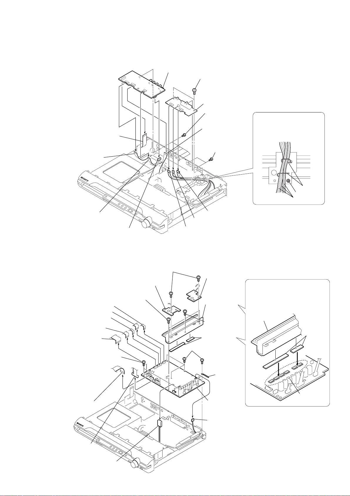
3-5. IO-S TERMINAL BOARD, SPEAKER BOARD
7
IO-S TERMINAL board
qd
SPEAKER board
qs
two screws (+BV 3 × 6)
6
five screws
(+BVTP 3
×
8)
4
wire (flat type)
9core (CN303)
1
connector
(CN302)
3
wire (flat type)
11core (CN201)
5
wire (flat type)
17core (CN301)
2
wire (flat type)
7core (CN304)
qa
two screws
(+BVTP 3
×
8)
screw
lead pin
When assembling,
clamp the three harnesses with
a lead pin or a similar tool so
that they do not touch this screw.
three harnesses
8
connector (CN303)
9
connector (CN302)
q;
connector (CN301)
HCD-DZ820KW
3-6. MAIN BOARD
1
wire (flat type)
11core (CN651)
2
wire (flat type) 11core (CN701)
3
wire (flat type) 7core (CN702)
4
wire (flat type)
17core (CN601)
5
wire (flat type)
23core (CN501)
qj
four screws (+BV 3 × 6)
6
wire (flat type)
13core (CN504)
q;
qa
HEATSINK A board
qd
two screws
(+BV 3
two screws (+BV 3 × 6)
×
10)
qs
HEATSINK B board
qg
heatsink (AMP)
qf
screw
(+BVTP 3
qh
two radiation
sheet
qk
four screws (+BV 3 × 6)
ql
clamp
w;
MAIN board
9
connector
(CN3000)
When re-assembling, attaching the
two heat radiation sheets on the
IC MAIN board first, and then attach
the heat sink (AMP).
heatsink (AMP)
×
12)
radiation
sheets
IC on the
MAIN board
7
connector (CN506)
8
connector
(CN3002)
15

HCD-DZ820KW
3-7. DMB12 BOARD
3
2
5core (CN202)
1
13core (CN109)
5
connector (CN601)
4
wire (flat type)
24core (CN101)
connector (CN201)
wire (flat type)
wire (flat type)
q;
6
wire (flat type)
11core (CN4301)
DMB12 board
9
seven screws (+BV 3 × 6)
7
wire (flat type)
11core (CN4501)
8
screw (+B 3 × 6)
3-8. DIAT-TX BOARD
2
connector (CN201)
5
four screws (+BV 3 × 6)
6
DIAT-TX board
3
wire (flat type)
11core (CN801)
4
screw
(+B 3 × 6)
1
Remove the
harness.
16

3-9. DC FAN, TUNER UNIT
)
r
2
wire (flat type)
9core
3
tuner unit
1
two screws (+BVTT 3 × 6)
6
two screws
(+BVTT 4
HCD-DZ820KW
4
two screws
(+BVTP 3
×
8)
5
cover (fan)
×
8
3-10. POWER BOARD
2
cover (top)
8
POWER board
4
connector
(CN903)
1
two screws
(+BVTP 3 × 8)
7
seven screws
(+BV 3 × 8)
5
connector
(CN3002)
7
DC fan
3
connector
(CN506)
When re-assembling, attach the
heat radiation sheets on the
chassis, and then install the
POWER board.
radiation sheets
6
connecto
(CN901)
17

HCD-DZ820KW
3-11. DVD MECHANISM DECK (CDM85-DVBU102)
7
three screws (+BV 3 × 6)
8
cover (MD)
9
three screws (+BV 3 × 6)
3
wire (flat type) 24
(CN101)
6
Remove the wire and harness.
core
1
two screws
(+BVTP 3
×
8)
qa
DVD mechanism deck
(CDM85-DVBU102)
q;
wire (flat type) 5
5
wire (flat type) 5
(CN202)
4
3-12. TRAY
1
Move the chuck cam
in the direction of the arrow.
core
core
connector (CN201)
bottom side
two claws
3
2
cover (top)
18
2
4
5
tray

3-13. BELT, MS-203 BOARD
2
chuck cam
3
HCD-DZ820KW
belt
7
MS-203 board
6
DC motor
1
two claws
5
three claws
4
screw
(M 1.7 × 2.5)
19
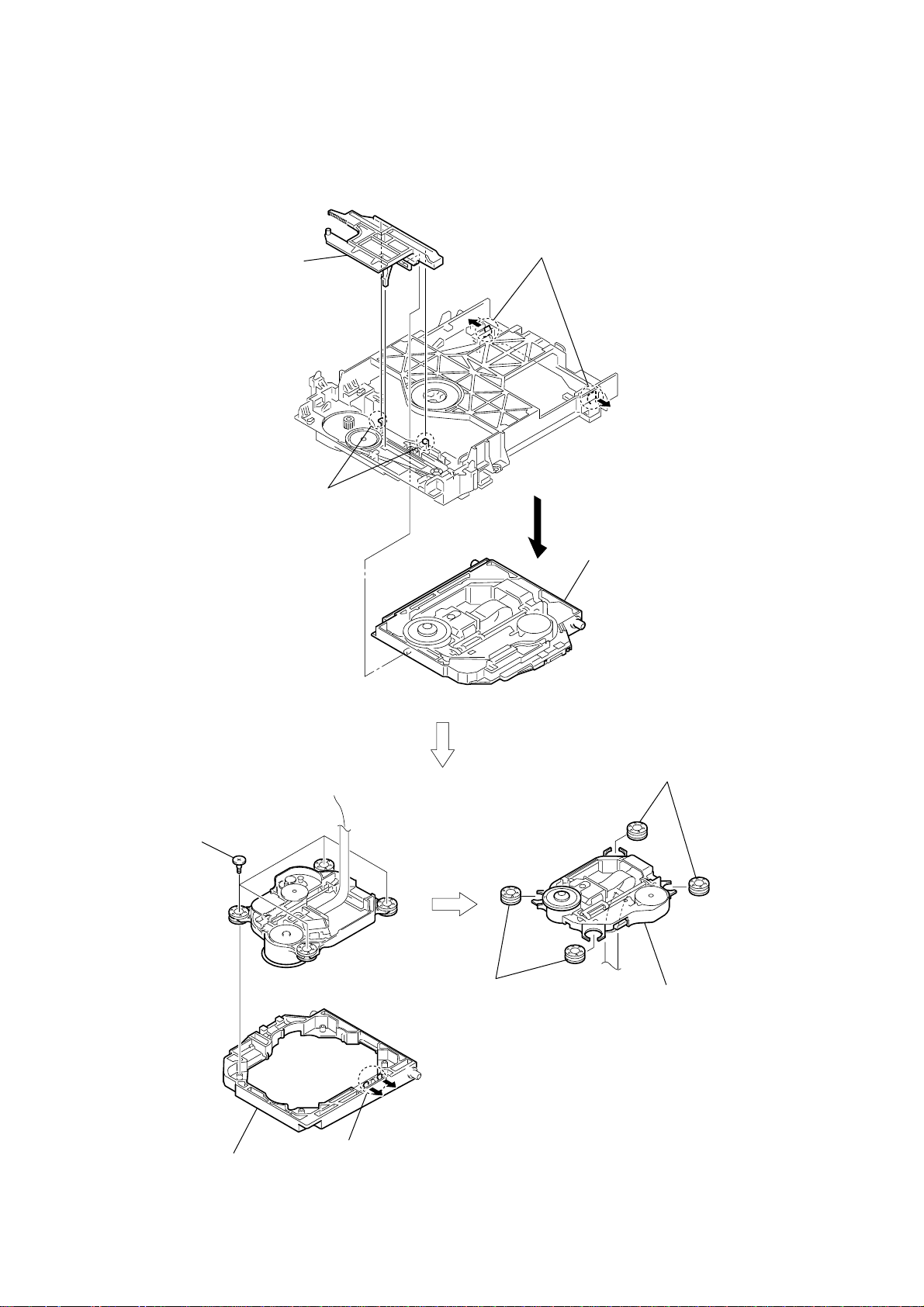
HCD-DZ820KW
3-14. OPTICAL PICK-UP (KHM-310CAA)
2
chuck cam
3
two claws
6
four insulator screws
1
two claws
4
base unit
8
two insulators
20
7
bu holder
5
two claws
9
two insulators
0
optical pick-up
(KHM-310CAA)

SECTION 4
TEST MODE
HCD-DZ820KW
Ver. 1.1
Note 1: Regarding the notification symbol “R”
Because the number of the operating buttons of this product
are limited, some operations require use of the operating
buttons of the remote commander, When a specific operation
requires use of the operating buttons of the remote
commander, “R” is added to the specific operating procedure
in this manual. Example MENU/NO “R” The MENU/NO
button of remote commander.
Note 2: Incorrect operations may be performed if the test mode is
not entered properly.
In this case, press the ?/1 button to turn the po wer of f, and
retry to enter the test mode.
1. Cold Reset
• The cold reset clears all data including preset data stored in
the RAM to initial conditions. Execute this mode when
returning the set to the customers.
Procedure:
1. Press the ?/1 button to turn the power on.
2. Press three buttons x , A and ?/1 simultaneously.
3. When this button is operated, display as “COLD RESET” for
a while and all of the settings are reset.
2. Panel Test Mode
•This mode is used to check the software version, FL, LED
and KEY.
2-1. Display Test Mode
Procedure:
1. Press the ?/1 button to turn the power on.
2. Press three buttons X , . and A simultaneously.
3. When the display test mode is activated, all segments and LEDs
are turned on.
4. To e xit from this mode, press three buttons X , . and A
simultaneously.
2-2. V ersion T est Mode
Procedure:
1. When the display test mode is activated, press the . button
and the message “DSX7KFW” is displayed, the version test
mode is activated.
2. Whenever the . button is pressed, the display changes in
the following order.
“DSX7KFW” (Model name) t “XX*1” (Destination) t MC
TM T DSP T TA T ST T DVD T UI T SYS
*1: Changes depending on destination.
3. Press the > button and the date of the software production
is displayed.
4. Press the > button again and the version is displayed.
5. To e xit from this mode, press three buttons X , . and A
simultaneously.
2-3. Key Test Mode
Procedure:
1. When the display test mode is activated, press the H button,
to select the key test mode.
2. To enter the KEY test mode, the fluorescent indicator displays
“K0 V0”. Each time a button is pressed, “KEY” value
increases. However, once a button is pressed, it is no longer
taken into account. When all keys are pressed correctly, “K8
V0” is displayed.
3. When the VOLUME control is turned in the direction of (+),
“V0” is changed to “V1”, then ... “V9”.
When the V OLUME control is turned in the direction of (–),
“V0” is changed to “V9”, then ... “V1”.
4. To e xit from this mode, press three buttons X , . and A
simultaneously.
3. Disc Tray Lock
The disc tray lock function for the antitheft of an demonstration
disc in the store is equipped.
Setting Procedure :
1. Press the ?/1 button to turn the set on.
2. Press the FUNCTION button to set DVD function.
3. Insert a disc.
4. Press the x button and the A button simultaneously for five
seconds.
5. The message “LOCKED” is displayed and the tray is locked.
Releasing Procedure :
1. Press the x button and the A button simultaneously for five
seconds again.
2. The message “UNLOCKED” is displayed and the tray is
unlocked.
Note: When “LOCKED” is displayed, the slot lock is not released by
turning power on/off with the ?/1 button.
4. DVD Ship Mode
• Use this mode when returning the set to the customer after
repair.
Procedure:
1. Press the ?/1 button to turn the set on.
2. Press the FUNCTION button to set the function “DVD”.
3.
Remove all discs, and then press two buttons x and
simultaneously.
4. After a message “MECHA LOCK” is displayed on the
fluorescent indicator tube, pull out the AC plug.
5. To exit from this mode, press the ?/1 button to turn the set on.
5. AM Step Change
•A step of AM channels can be changed over between 9 kHz
and 10 kHz.
Procedure:
1. Press the ?/1 button to turn the set ON.
2. Select the function “TUNER”, and press FUNCTION button
to select the BAND “AM”.
3. Press the ?/1 button to turn the set OFF.
4. Press two buttons > and ?/1 simultaneously, and the
display of fluorescent indicator tube changes to “AM 9 k
STEP” or “AM 10 k STEP”, and thus the channel step is
changed over.
6. V olume Test Mode
Procedure:
1. Press the ?/1 button to turn the power on.
2. Press three buttons . , H and > simultaneously.
3. The message “VOLUME MAX” is displayed, when the
VOLUME control is turned in the dirction of (+).
The message “VOLUME MIN” is displayed, when the
VOLUME control is turned in the dirction of (–).
4. To exit from this mode, press the ?/1 button to turn the set off.
7. Product Out
This mode moves the optical pick-up to the position durable to
vibration and clears all data including preset data stored in the RAM
to initial conditions. Use this mode when returning the set to the
customer after repair.
Procedure:
1. Press the ?/1 button to turn the power on.
2. Press the FUNCTION button to set the function “DVD”.
3.
Remove all discs, and then
?/1 simultaneously.
4. After the “ST ANDBY” blinking display finishes, the message
“MECHA LOCK” is displayed on the fluorescent indicator
tube disconnect the A C po wer plug, then the ship mode is set.
press three buttons > , A and
.
21

HCD-DZ820KW
Ver. 1.1
DVD SECTION
8-1. GENERAL DESCRIPTION
The IOP measurement allows you to make diagnosis and adjustment
simply by using the remote commander and monitor TV. The
instructions, diagnosis results, etc. are given on the on-screen display
(OSD).
Be sure to execute the IOP measurement when a BU (Base Unit) is
replaced.
8-2. HOW TO ENTER TEST MODE
While pressing the x and A buttons simultaneously, turn
VOLUME + with the DVD player in power on.
The T est Mode starts, then the menu shown belo w will be displayed
on the TV screen.
Remocon Diagnosis Menu
0. External Chip Check
1. Servo Parameter Check
2. Drive Manual Operation
3. Emergency History Check
4. Version Information
1
Model Name : DSX7KFW_ XX
IF-con : V
Syscon : Ver.
*1: Changes depending on destination
er. XX.XX (XXXX)
X.XXX
The menu above is the Remocon Diagnosis Menu screen which
consists of five main functions. At the bottom of the menu screen, the
model name and IF-con version. To exit from the Test Mode, press
the power button on the remote commander.
8-3. EXECUTING IOP MEASUREMENT
In order to execute IOP measurement, the following standard
procedures must be followed.
(1) In power on, while pressing the x and A buttons
simultaneously, turn VOLUME + .
Remocon Diagnosis Menu
0. External Chip Check
1. Servo Parameter Check
2. Drive Manual Operation
3. Emergency History Check
4. Version information
*
(2) Select “2. Drive Manual Operation” by pressing the 2 “R”
button on the remote commander. The screen will appear as
below.
Drive Manual Operation
1. Servo Control
2. Track/Layer Jump
3. Manual Adjustment
4. Tray Aging Mode
5. MIRR time adjust
0. Return to top Menu
(3) Select “3. Manual Adjustment” by pressing the 3 “R” b utton
on the remote commander. The screen will appear as below.
Manual Adjust
1. Track Balance Adjust:
2. Track Gain Adjust:
3. Focus Balance Adjust:
4. Focus Gain Adjust:
5. Eq boost Adjust:
6. Iop:
7. TRV. Level:
8. S curve(FE) Level:
9. RFL(PI) Level:
0. MIRR Time:
o O Change Value
[RETURN] Return to previous menu
(4) Select Iop by pressing the 6 “R” button on the remote
commander.
(5) Wait until a hexadecimal number appear.
Manual Adjust
1. Track Balance Adjust:
2. Track Gain Adjust:
3. Focus Balance Adjust:
4. Focus Gain Adjust:
5. Eq Boost Adjust:
6. Iop. 53:
7. TRV. Level:
8. S curve(FE) Level:
9. RFL(PI) Level:
0. MIRR Time:
Change Value
[0] Return to previous menu
Model Name
IF-con : Ver. XX.XX (XXXX)
Syscon : Ver. X.XXX
*1: Changes depending on destination
: DSX7KFW_ XX
22
1
*
(6) Convert each data from hexadecimal to decimal using
conversion table.
(7) Please find the label on the rear of the BU (Base Unit).
The default IOP value is written in the label.
(8) Subtract between these two values.
(9) If the remainder is smaller than 93 (decimal), then it is OK.
Ho wever if the v alue is higher than 93, then the BU is defecti ve
and need to be change.
(10) Press the RETURN “R” button to return back to previous
menu.
(11) Press the 0 “R” button to return to Top Menu and power
off the DVD Player.

HCD-DZ820KW
Ver. 1.1
8-4. EMERGENCY HISTORY
To check the emergency history, please follow the following
procedure.
(1) From the Top Menu of Remocon Diagnosis Menu, select “3.
Emergency History Check” by pressing the 3 “R” button on
the remote commander. The following screen appears on the
on-screen display.
Emg.History Check
Laser Hours CD 999h 59min
1. 01 05 04 04
00 00 00 00 00 00 23 45
2. 02 02 01 01 00 A9 4B 00
00 00 00 00 00 00 23 45
Next Next Page Prev Prev Page
O Return to Top Menu
DVD 999h 59min
00 92 46 00
(2) Y ou can check the total time when the laser is turned on during
playback of DVD and CD from the abov e menu. The maximum
time, which can be displayed are 999h 59min.
(3) You can check the error code of latest 10 emergency history
from the above menu. To view the previous or next page of
emergency history , press . “R” or > “R” on the remote
commander. The error code consists of the following three
blocks. The first block indicates the error code. The second
block indicates the parameter and the third block indicates the
time of error code as shown below.
• Error Code
Emg.History Check
Laser Hours CD 999h 59min
*1*
2
1. 01 05 04 04
00 00 00 00 00 00 23 45
2. 02 02 01 01 00 A9 4B 00
00 00 00 00 00 00 23 45
Next Next Page Prev Prev Page
O Return to Top Menu
DVD 999h 59min
00 92 46 00
*
3
*1 : Error Code
*2 : Parameter of error code
*3 : Time of error code
The meaning of error code is as below:
01: Communication error (No reply from syscon)
02: Syscon hung up
03: Power OFF request when syscon hung up
19: Thermal shutdown
24: MoveSledHome error
25: Mechanical move error (5 Changer)
26: Mechanical move stack error
30: DC motor adjustment error
31: DPD offset adjustment error
32: TE balance adjustment error
33: TE sensor adjustment error
34: TE loop gain adjustment error
35: FE loop gain adjustment error
36: Bad jitter after adjustment
40: Focus NG
42: Focus layer jump NG
52: Open kick spindle error
51: Spindle stop error
60: Focus on error
61: Seek fail error
62: Read Q data/ID error
70: Lead in data read fail
71: TOC read time out (CD)
80: Can’t buffering
81: Unknown media type
8-4-1. Clear the Laser Hour
Press DISPLAY “R” button and then press CLEAR “R” button.
The data for both CD and DVD data are reset.
Emg.History Check
Laser Hours CD 0h 0min
1. 01 05 04 04
00 00 00 00 00 00 23 45
2. 02 02 01 01 00 A9 4B 00
00 00 00 00 00 00 23 45
Next Next Page Prev Prev Page
O Return to Top Menu
DVD 0h 0min
00 92 46 00
8-4-2. Clear the Emergency History
Press TOP MENU “R” button and then press CLEAR “R” button.
The error code for all emergency history would be reset.
Emg.History Check
Laser Hours CD 999h 59min
1. 00 00 00 00
00 00 00 00 00 00 00 00
2. 00 00 00 00 00 00 00 00
00 00 00 00 00 00 00 00
Next Next Page Prev Prev Page
O Return to Top Menu
DVD 999h 59min
00 00 00 00
8-4-3. Clear the Initialize Setup Data
Press MENU “R” button and then press CLEAR “R” button on
the remote commander.
23

HCD-DZ820KW
Ver. 1.1
8-4-4. Return to the Top Menu of Remocon Diagnosis
Menu
Press 0 “R” button on the remote commander.
• Check Version Information
To check the version information, please follow the following
procedure.
(1) From the Top Menu of Remocon Diagnosis Menu, select “4.
Version Information” by pressing the 4 “R” button on the
remote commander. The following screen appears on the onscreen display.
Version information
Firm (Main) : Ver. xxxxx
Firm (Sub) : xxxxx
RISC : xxxxx
8032 : xxxxx
Audio DSP : xxxxx
Servo DSP : xxxxx
O Return to Top Menu
To return to the T op Menu of Remocon Diagnosis Menu, press
0 “R” on the remote commander.
24

SECTION 5
)
ELECTRICAL ADJUSTMENT
HCD-DZ820KW
Ver. 1.1
DVD SECTION
When the base unit is replaced, perform the adjustment and the
measurement as shown below in this order.
EXECUTING IOP MEASUREMENT (See page 22)
[TEST DISC LIST]
Be sure to use the DVD disc that matches the signal standards of
your region.
• CD YEDS-18 (Part No.: 3-702-101-01)
PATD-012 (Part No.: 4-225-203-01)
• DVD SL (Single Layer)
NTSC : HLX-503 (Part No.: J-6090-069-A)
HLX-504 (Part No.: J-6090-088-A)
PAL : HLX-506 (Part No.: J-6090-077-A)
• DVD DL (Dual Layer)
NTSC : HLX-501 (Part No.: J-6090-071-A)
HLX-505 (Part No.: J-6090-089-A)
PAL : HLX-507 (Part No.: J-6090-078-A)
[RF Level Check]
Connection:
oscilloscope
DMB12 board
CN105 pin 6 (RFMON)
CN105 pin 3 (GND)
+
–
Checking Location: DMB12 board (Side A)
DMB12 BOARD
HDMI OUT
(DVD ONLY)
(SIDE A)
CN105 Pin 3 (GND)
CN105 Pin 6 (RFMON)
OPTICAL PICK-UP
(KHM-310CAA)
BLOCK
IC101
IC201
1
CN105
3
6
SPINDLE MOTOR
SLED MOTOR
Procedure:
1. Connect an oscilloscope to CN105 pin 6 (RFMON) and
CN105 pin 3 (GND) on the DMB12 board.
2. Turn the power on.
3. Insert the CD test disc (refer to the TEST DISC LIST), and
press the H button to play the disc back.
4. Confirm that oscilloscope waveform is clear and check RF
signal level is correct or not.
Note: A clear RF signal waveform means that the shape “◊” can be
clearly distinguished at the center of the waveform.
5. Eject the CD disc, and insert the DVD SL test disc (refer to
the TEST DISC LIST), and press the H button to play the
disc back.
RF signal waveform
VOLT/DIV: 200 mV
TIME/DIV: 500 ns
level: 0.57 to 1.1 Vp-p (CD)
0.58 to 1.23 Vp-p (DVD
25

HCD-DZ820KW
C
B
These are omitted.
E
Q
SECTION 6
DIAGRAMS
THIS NOTE IS COMMON FOR PRINTED WIRING BOARDS AND SCHEMATIC DIAGRAMS.
(In addition to this, the necessary note is printed in each block.)
For Schematic Diagrams.
Note:
• All capacitors are in µF unless otherwise noted. (p: pF)
50 WV or less are not indicated except f or electrolytics and
tantalums.
• All resistors are in Ω and 1/
specified.
• f : internal component.
• C : panel designation.
Note: The components identified by mark 0 or dotted
line with mark 0 are critical for safety.
Replace only with part number specified.
✩ New part of EEP ROM (IC103, IC706) on the DMB12 board
cannot be used. Theref ore , if the mounted DMB12 board (A1166-695-A, A-1166-728-A) is replaced, exchange new EEP
ROM (IC103, IC706) with that used before the replacement.
• A : B+ Line.
•Voltages and wavef orms are dc with respect to ground under no-signal (detuned) conditions.
•Voltages and wavefor ms are dc with respect to ground in
service mode.
•Waveforms are taken with a oscilloscope.
Voltage variations may be noted due to normal production
tolerances.
no mark : DVD STOP
* : Impossible to measure
•Voltages are taken with VOM (Input impedance 10 MΩ).
• Circled numbers refer to waveforms.
• Signal path.
F : AUDIO
J : CD PLAY
c : DVD PLAY
I : SACD PLAY
d : TUNER
L : VIDEO
E : Y
a : CHROMA
r : COMPONENT VIDEO
f : AUDIO IN
h : DIGITAL IN (OPTICAL IN)
i : DIGITAL IN (COAXIAL IN)
N : MIC
•Abbreviation
AUS: Australian model
E3 : 240V AC area in E model
KR : Korean model
RU : Russian model
SP : Singapore model
4
W or less unless otherwise
For Printed Wiring Boards.
Note:
• X : parts extracted from the component side.
• a : Through hole.
• : Pattern from the side which enables seeing.
(The other layers' patterns are not indicated.)
Caution:
Parts face side: Parts on the parts face side seen from
(SIDE A) the parts face are indicated.
Pattern face side: Parts on the pattern face side seen from
(SIDE B) the pattern face are indicated.
• Indication of transistor.
CEB
These are omitted
26

HCD-DZ820KW
• Circuit Boards Location
DIAT-TX board
SW board
DMB12 board
MS-203 board
TUNER UNIT
DDCON board
IO-S TERMINAL board
POWER board
FL board
JACK board
SPEAKER board
MAIN board
HEATSINK B board
HEATSINK A board
– MAIN Board – – IO-S TERMINAL Board –
0 IC702 ws (XIN(I))
81.3 ns
1 V/DIV, 40 ns/DIV
qa IC2 <zvx (CLKIN)
40 ns
1 V/DIV, 20 ns/DIV
qs IC501 qg (Xin)
3.6 Vp-p
2.5 Vp-p
qf
IC201 wh (COUT)
H
1 V/DIV, 20 µs/DIV
qg
IC201 qk (CbOUT)
H
500 mV/DIV, 20 µs/DIV
qh
IC201 wa (YOUT)
2.0 Vp-p
1.6 Vp-p
2.2 Vp-p
– DIAT-TX Board –
ql
IC804 tj (OSC1)
40.6 ns
500 mV/DIV, 20 ns/DIV
2.3 Vp-p
•Waveforms
– DMB12 Board –
1
IC101 6 (DVDRFIP)
200 mV/DIV, 100 ns/DIV
2
IC101 <xx. (XTALI)
37 ns
1 V/DIV, 10 ns/DIV
800 mVp-p
4.2 Vp-p
4
IC101 <z., (YUV3)
H
500 mV/DIV, 20 µs/DIV
5
IC101 <z.n (YUV2)
H
1 V/DIV, 20 µs/DIV
1.1 Vp-p
0.7 Vp-p
7
IC101 <x// (YUV4)
1 V/DIV, 20 µs/DIV
8
IC101 <x/x (YUV5)
H
500 mV/DIV, 20 µs/DIV
200 ns
1 V/DIV, 100 ns/DIV
qd IC3010 rk (XFSOIN)
1.1 Vp-p
20.3 ns
1 V/DIV, 10 ns/DIV
H
0.7 Vp-p
2.7 Vp-p
5.5 Vp-p
1 V/DIV, 20 µs/DIV
qj
IC201 qh (CrOUT)
H
500 mV/DIV, 20 µs/DIV
qk
IC201 w; (CYOUT)
1 V/DIV, 20 µs/DIV
H
1.6 Vp-p
2.2 Vp-p
H
3
IC708 qg (X1)
1 V/DIV, 40 ns/DIV
HCD-DZ820KW
100 ns
3.8 Vp-p
6
IC101 <z.v (YUV1)
1 V/DIV, 20 µs/DIV
9
IC101 <x/c (YUV6)
1.1 Vp-p
H
500 mV/DIV, 20 µs/DIV
H
0.6 Vp-p
2727

HCD-DZ820KW
6-1. BLOCK DIAGRAM – RF SECTION –
RF
A
LIMIT
CD LD
B
C
D
F
E
VC
C
B
A
D
Q102 (1/2)
AUTOMATIC POWER
CONTROL (FOR CD)
DETECTOR
OPTICAL PICK-UP
BLOCK
(KHM-310CAA)
LASER
DIODE
(FOR CD)
IC652
STREAM PROCESSOR
BCKO
XRST
13
LRCKO
24
BCKO
25
D2
23RCKI
LRCK
MCK
LRCK0
BCKO
MCKO
SO_B
I
BCK
D1
D2
D3
DIAT SECTION
F
AMP SECTION
(Page 29)
AUDIO SECTION
A
(Page 30)
AMP SECTION
H
(Page 29)
(Page 32)
LRCKO
LRCKI RST
6
BCKO
5
BCKI
D2
CN105
RFMON
DVDRFIP
6
OSP
252 253
DVDA
2
DVDB
3
DVDC
4
DVDD
5
19
TPI
18
TNI
A
8
MA
B
9
MB
D
10
MC
C
11
MD
29
V2O
176
LI M SW
23
LD01
OSN
IC101 (1/2)
CD/DVD RF AMP,
FOCUS/TRACKING ERROR AMP
DVD SYSTEM PROCESSOR
DIGITAL SERVO PROCESSOR
ASDATA2
V2REFO
RXD
TXD
ALRCK
ABCK
ASDATA0
ASDATA1
ACLK
28
106
107
213
214
217
218
219
215
6
5
V2REFO
2
RXD
1
TXD
IC4501 BUFFER
4
5
8
7
Y
(Page 31)
IC501 (1/4)
DIAT_XRST
14
4
6
IC4502 BUFFER
2
A
VIDEO SECTION
B
SYSTEMCONTROLLER
TO DIAG JIG
16
15
12
13
65
MCKO
LRCKO
4
SDIN
2
SDOUT
LASER
DIODE
(FOR DVD)
2AXIS
DEVICE
FOCUS/
TRACKING
COIL
(SPINDLE MOTOR)
PD
DVD LD
VR650
VR780
MSW
FCS+
FCS–
TRK+
TRK–
(SLED MOTOR)
Q102 (2/2)
AUTOMATIC POWER
CONTROL (FOR DVD)
Q101, Q103
VOLUME CONTROL
REG02
+3.6V
REG01
+2.5V
MM
SP+
MM
SP–
20
MD12
MD11
21
LD02
22
MSW
48
FOCUS/TRACKING COIL DRIVER,
SPINDLE, SLED MOTOR DRIVER
IOP
42
41
36 48
37 1
35 3
34 4
32
31
SL–
30
SL+
29
27
28
46
47
IC201
BUFFER
FOCUS COIL
DRIVE
TRACKING COIL
DRIVE
SLED MOTOR
DRIVE
SLED MOTOR
DRIVE
SPINDLE MOTOR
DRIVE
BUFFER
38
MTK_RST
SCO
99
IFSCK
98
IFSDO
101
IFSDI
100
XIFCS
114
XIF5SY
FMO
FOO
DMO
TRO
39
TROPENPWM
38
FMO
42
FOO
37
DMO
41
TRO
V REFO
30
40
IOPMON
47
SPFG
184
MUTE123
183
MUTE
181
TSDM
15
9
12
43
10
13
40
45
19
20
22
21
VREFO
FOO
TRO
FMO
DMO
SCD
SID
33
DVD_SCO
32
DVD_SOD
31
DVD_SID
37
DVD_XIFCS
34
DVD_XIFBUSY
XM_SC_RX_IN/
KARAOKE MODE
XM_SC_TX_OUT/
MIC_DET_OUT
CDM_OPEN_SW
CNVss
POWER SECTION
(Page 33)
36
35
KARAOKE MODE
MIC
VIDEO SECTION
J
(Page 31)
27
9
CN503
CNVss
3
RTSI
7
2
C
RESET
TO WRITE JIG
CLKI
5
RXDI
4
8
TXDI
• Signal Path
: CD PLAY
: DVD PLAY
: SACD PLAY
: AUDIO
(CHUK/TRAY DETECT)
HCD-DZ820KW
S001
(LOADING)
MM
LDM+
LDM-
CKSW
OCSW
24
25
LOADING
MOTOR
17
16
185
186
49
50
REW
FWD
CKSW
OCSW
2828
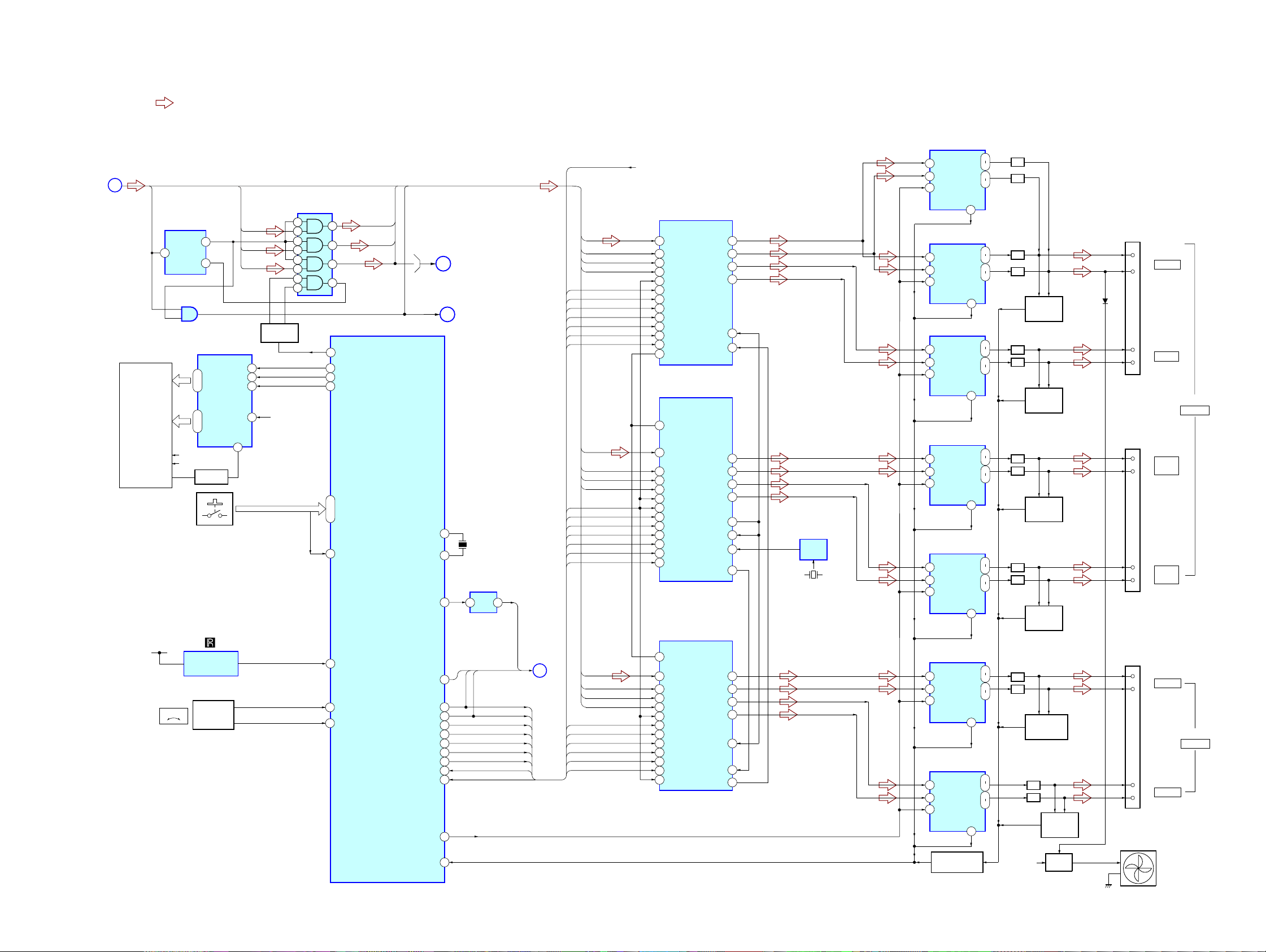
6-2. BLOCK DIAGRAM – AMP SECTION –
• Signal Path
: AUDIO
Q781
SWITCH
VFLVFL
MCKO,
4
5
10
9
1
2
13
12
AUDIO
SECTION
(Page 30)
E
FLUORESCENT
INDICATOR TUBE
LRCKO
FL801
S801 – S808
(FUNCTION KEY)
E3.3V
2
CLK
G1
VOLUME
–
AND GATE
1
2
IC782
D FF
4
Q
1
D
IC90
4
FL DRIVER
14 – 29
AD2 – AD1,S1–S35
31–41
G1 – G10
F1
F2
Q802
FL DRIVER
IC801
REMOTE CONTROL
RECEIVER
S800
VOLUME
+
ENCODER
IC802
DIN
CLK
STB
42
AMP_D1
AMP_D3
AMP_D2
7
8
9
56
GR1
BCKO
IC781
AND GATE
KEY0
6
8
AMP_D2
3
11
SYSTEM CONTROLLER
61
DIR_XSTATE
24
FD_OUT/LED_ DATA
21
FL_CLK/LED_ CLK
25
FL_CS/STB
97,95,94
KEY0 – KEY2
74
KEY INT
4
SIRCS_IN
10
ENA
11
ENB
AMP_D1
AMP_D3
IC501 (2/4)
AMP_
LRCK
Xout
DIAT_
CSOD
DIAT_XSCEN
DIAT_SDATA
DIAT_SCLK
DAMP LAT1
DAMP LAT2
DAMP LAT3
DAMP INIT
DAMP SOFT MUTE
OVERFLOW1
OVERFLOW2
DRIVE RST
DRIVE OCP
Xin
D1-D3,
RF SECTION
H
RF SECTION
I
13
15
23
66
1
2
47
48
49
50
51
44
45
42
43
(Page 28)
BCKO,LRCK
MCKO,
(Page 28)
X501
5MHz
IC651
INVERTER
Y
B
,
CSOD
SOFTMUTE
RESET
DIAG
4 2
SDATA XLAT,SCLK
SCDT
SHIFT
LAT1
LAT2
LAT3
INIT
OVF
OVF2
G
DIAT
SECTION
(Page 32)
NSPMUTE
MCK0
BCK0
LRCK
OVF2
SCDT
SHIFT
LAT3
INIT
NSPMUTE
SOFTMUTE
AMP_D1
MCK0
BCK0
LRCK
OVF
SCDT
SHIFT
LAT1
INIT
NSPMUTE
SOFTMUTE
AMP_D2
MCK0
BCK0
LRCK
SCDT
SHIFT
LAT2
INIT
NSPMUTE
SOFTMUTE
AMP_D3
+3.3v
S-MASTER PROCESSOR
31
DATA
36
XFSIIN
30
BCK
29
LRCK
25
FLAGL OVF
24
OVF FLAGR
21
SCDT
22
SCSHIFT
23
SCLATCH
27
INIT
18
NSPMUTE
19
SOFTMUTE
20
PGMUTE
S-MASTER PROCESSOR
20
PGMUTE
31
DATA
36
XFSIIN
30
BCK
29
LRCK
25
FLAGL OVF
24
OVF FLAGR
21
SCDT
22
SCSHIFT
23
SCLATCH
27
INIT
18
NSPMUTE
19
SOFTMUTE
S-MASTER PROCESSOR
20
PGMUTE
31
DATA
36
XFSIIN
30
BCK
29
LRCK
25
FLAGL OVF
21
SCDT
22
SCSHIFT
23
SCLATCH
27
INIT
18
NSPMUTE
SOFTMUTE
19
OVF FLAGR
24
IC3030
IC3010
FSOCKOUT
IC3020
OUTL1
OUTL2
OUTR1
OUTR2
FS0I
XFS0IN
OUTR1
OUTR2
OUTL1
OUTL2
FS0I
XFS0IN
XFS0OUT
OUTR1
OUTR2
OUTL1
OUTL2
FS0I
XFS0IN
XFS0OUT
HCD-DZ820KW
IC3500
S-MASTER DIGITAL AMP
28
14
PWMB
OUTA
PWMA
6
5
11
9
6
4
38
48
6
4
11
9
37
38
48
14
6
4
11
9
38
48
14
WF
WF
C
C
FR
FR
FL
FL
49.152MHz
IC3051
OSC
X3501
SR
SR
SL
SL
S-MASTER DIGITAL AMP
14
6
5
S-MASTER DIGITAL AMP
6
14
5
S-MASTER DIGITAL AMP
14
6
5
S-MASTER DIGITAL AMP
6
14
5
S-MASTER DIGITAL AMP
14
6
5
S-MASTER DIGITAL AMP
6
14
5
OUTB
RESET
IC3400
PWMB
OUTB
PWMA
OUTA
RESET
4
IC3300
PWMA
OUTA
PWMB
OUTB
RESET
4
IC3100
PWMB
OUTB
PWMA
OUTA
RESET
4
IC3150
PWMA
OUTA
PWMB
OUTB
RESET
4
IC3200
PWMB
OUTB
PWMA
OUTA
RESET
4
IC3250
OUTA
PWMB
PWMA
OUTB
RESET
4
Q3551
PROTECT DETECT
SD
4
SD
SD
SD
SD
SD
SD
LPF
30
25
LPF
27
25
LPF
27
28
LPF
30
DC
DETECT
FAN
DRIVE
D3551
Q3401,3402
DC
DETECT
28
LPF
30
25
LPF
27
Q3301,3302
DC
DETECT
25
LPF
27
28
LPF
30
Q3101,3102
DC
DETECT
28
LPF
30
25
LPF
27
Q3151,3152
DC
DETECT
25
LPF
27
28
LPF
30
Q3201,3202
DC
DETECT
28
30
25
27
LPF
LPF
Q3251,3252
+12V
Q3000-3002
FAN
(+)
(–)
(+)
(–)
(+)
(–)
(+)
(–)
(+)
(–)
(+)
(–)
WOOFER
CENTER
FRONT
R
FRONT
L
SUR R
SUR L
TB301
SPEAKER
TB302
SPEAKER
HCD-DZ820KW
2929

HCD-DZ820KW
6-3. BLOCK DIAGRAM – AUDIO SECTION –
J401
TV/VCR1
TV/VCR2
J402
MIC2
DIGITAL IN
OPTICAL
DIGITAL IN
COAXIAL
TV/VCR1
AUDIO IN/
MIC1/
A.CAL MIC
BUFFER
J203
AM
FM
Ω
75
IC371
IC301
OPTICAL
(1/3)
L
R
COAXIAL
J302
IN
OUT
Q470-473,476
MO/ST DETECT
D470
Q477,478
PLUG DET
8
7
VIN2
VIN1
1
2
1
L
R
TUNER
UNIT
L
R
VOUT2
VOUT1
5
4
CLK
DATA
L-CH
R-CH
6
5
3
2
TUNED
PLL CK
PLL DO
PLL CE
PLL DI
IC401
AMP
–
+
+
–
AUDIO AMP
5
6
3
2
Q393
Q391
7
1
GAIN CONT
IC402
–
+
+
–
2
3
Q474,475
D433
–
+
7
1
GAIN CONT
IC372
COMPARATOR
1
MIC CLK
MIC DATA
Q300,310,320
MUTING
DC CONT
MO/ST DET
PLUG DET1
• Signal Path
: AUDIO
: AUDIO IN
: TUNER
: MIC
: DIGITAL IN(OPTICAL IN)
: DIGITAL IN(COAXIAL IN)
D432
D431
L-CH
R-CH
AUDIO INPUT SELECTOR
11
X3
L
15
X2
14
X1
L
X0
12
4
Y3
R
2
Y2
5
Y1
R
Y0
1
Q395
SOFT JIG
IC350
A
10B9
A SEL1
2
C CLK
I
2
I
C DATA
Q396
A SEL0
CN502
BCK
LRCKO
BCKO
DIR_CLK
DIR_RERR
D1
D2
D3
MCKO
MCK
DIN
DIR_DATA
57
SEL_SA_CD
BCK
3
DSP INTR
DIGITAL AUDIO PROCESSOR
D2
80
DAI-P13
D3
81
DAI-P14
87
DAI-P17
79
DAI_P12
94
DAI_P20
89
DAI_P19
88
DAI_P18
97
FLAG2
16
FLAG1
127
HDIN
78
DSPIA
15
FLAG1
122
SPIDS
DIN
56
5
DSP_SPIDS
DSP DIN/DIR DIN
IC2
DIR_CLK
DIR_HCE
DIR_HDOUT
63
7
59
DIR HDOUT
DSP DIN/DIR CLK
DAI_P16
DAI_P17
DAI_P20
XSTATE
61
58
DIR HCE
DIR XSTATE
CLKIN
XTAL
DSPOA
DSPOB
DSPOC
SPICLK
RESET
MISO
CSFLAG
DIR_RST
19
DIR RST
DIR_CSFLAG
142
143
86
87
94
64
65
70
125
121
126
DIR_ZERO
DIR_RERR
60
DIR_RERR18DIR_ZORO
LRCKO
BCKO
MCKO
X1
25MHz
D1
D2
D3
6
DSP_MISO
E
AMP
SECTION
(Page 29)
55
DSP_RESET
RF SECTION
9
7
4
12
BCK
LRCK
AUDIO
ERROR
XSTATE
CFALAG
DATA
DI
DO
CL
CE
(Page 28)
14
15
24
34
17
36
35
38
37
25
48
16
IC360
AUDIO AMP
L
13
X
R
3
Y
3
2
5
6
IC701
A/D CONVERTER
19
AINL
16
AINR
INVERTER
2
VIDEO
SECTION
(Page 31)
3
4
D
+
–
+
–
DOUT
MCLK
LRCK
BCLK
IC302
GAIN CONT
DC CONT
MO/ST DET
PLUG DET1
TUNED
PLL CK
PLL DO
PLL CE
PLL DI
4
1
7
2
1
3
6
V_SEL2
LIN
RIN
V_SEL0
V_SEL1
IC771
AND GATE
4
Y
B
A
1
2
12.288MHz
75
RDS_CLK
76
RDS_DATA
82
A-SEL0
A-SEL1
83
A-SEL2/A-CAL
91
MIC GAIN
26
DC CONT
28
MONO/ST DET
90
MIC/A CALSW
100
TUNED
69
ST_CLK
70
ST_DO
71
ST_CE
72
ST_DI
73
V_SEL0
79
V_SEL1
80
V_SEL2
84
I2C CLK
29
30
I2C DATA
X701
LRCK0
BCKO
D1
MCK0
IC704
SELECTOR
10 1
3B A/B
11
3A
3Y
6
2B
2Y
5
2A
3
1B
1Y
2
1A
4Y
14
4A
13
4B
IC702
DIGITAL AUDIO
INTERFACE
13 CKOUT
22
XIN
21
XOUT
4DIN1
5
DIN2
XMOD
49
58
DIR_RST
XSTATE
DIR_HDOUT
DIR_CLK
DIR_HCE
CS FLAG
DIR_RST
DIR_ZERO
A
MCK
IC501 (3/4)
SYSTEM CONTROLLER
HCD-DZ820KW
3030
 Loading...