

Sony HCDDZ-7-T Service manual
HCD-DZ7T
A
S
S
*
I
T
S
A
M
I
S
e
e
z
z
SERVICE MANUAL
Ver. 1.1 2007.06
HCD-DZ7T is the amplifier, DVD/CD
and tuner section in DAV-DZ7T.
This system incorporates with Dolby* Digital and Dolby Pro Logic (II)
adaptive matrix surround decoder and the DTS** Digital Surround System.
* Manufactured under license from Dolby Laboratories.
“Dolby”, “Pro Logic”, and the double-D symbol are trademarks of
Dolby Laboratories.
** Manufactured under license from DTS, Inc.
“DTS” and “DTS Digital Surround” are registered trademarks of DTS,
Inc.
SPECIFICATIONS
E Model
Model Name Using Similar Mechanism HCD-DZ150K
Mechanism T ype CDM85-DVBU102
Optical Pick-up Name
KHM-313CAA
mplifier section
tereo mode (rated) 108 W + 108 W (at 3 ohms,
urround mode (reference) RMS output power
Depending on the sound field settings and the source,
there may be no sound output.
nputs (Analog)
V (AUDIO IN) Sensitivity: 450/250 mV
AT/CABLE (AUDIO IN)Sensitivity: 450/250 mV
UDIO IN/MIC 1 Sensitivity:
IC 2 Sensitivity: 1 mV
nputs (Digital)
AT/CABLE (COAXIAL IN/OPTICAL IN)
9-887-704-02
2007F16-1
© 2007.06
1 kHz, 1 % THD)
FL/FR/SL/SR*: 143 watts
(per channel at 3 ohms, 1
kHz, 10 % THD)
C*: 142 watts
kHz, 10 % THD)
Subwoofer L/Subwoofer
R*: 143 watts (per channel
at 3 ohms, 80 Hz, 10 %
THD)
AUDIO IN 250/125 mV/
MIC 1 1 mV
Impedance: 75 ohms/–
(at 3 ohms, 1
Sony Corporation
Home Audio Division
Published by Sony Techno Create Corporation
DVD system
Laser Semiconductor laser
(DVD: λ = 650 nm)
(CD: λ = 790 nm)
Emission duration:
continuous
Signal format system
Mexican and Latin American models:
NTSC
Other models: NTSC/PAL
Tuner section
System PLL quartz-locked digital
synthesizer
FM tuner section
Tuning range 87.5-108.0 MHz (50 kHz
step)
Antenna (aerial) FM wire antenna (aerial)
Antenna (aerial) terminals 75 ohms, unbalanced
Intermediate frequency 10.7 MHz
AM tuner section
Tuning range
Mexican, and Latin American model s :
530 – 1,710 kHz (with the
interval set at 10kHz)
531 – 1,710 kHz (with the
interval set at 9 kHz)
Other models: 531 – 1,602 kHz (with th
Antenna (aerial) AM loop antenna (ae ri a l)
Intermediate frequency 450 kHz
Video section
Outputs VIDEO: 1 Vp-p 75 ohms
Inputs VIDEO: 1 Vp-p 75 ohms
General
Power requirements
Mexican models: 120 V AC, 60 Hz
Latin American models: 110 - 240 V AC, 50/60 H
Other models: 220 - 240 V AC, 50/60 H
DVD RECEIVER
interval set at 9 kHz)
530 – 1,610 kHz (with th
interval set at 10 kHz)
S VIDEO:
Y: 1 Vp-p 75 ohms
C: 0.286 Vp-p 75 ohms
COMPONENT:
Y: 1 Vp-p 75 ohms
PB/CB, PR/CR: 0.7 Vp-p
75 ohms
HDMI OUT: Type A (19
pin)
— Continued on next page —
HCD-DZ7T
Ver. 1.1
Power consumption
Mexican models: On: 180 W
Standby: 0.3 W (at the
Power Saving mode)
Latin American models: On: 190 W
Standby: 0.3 W (at the
Power Saving mode)
Other models: On: 180 W
Standby: 0.3 W (at the
Power Saving mode)
Dimensions (approx.) 430 × 63× 380 mm (w/h/d)
incl. projecting parts
Mass (approx.) 4.2 kg
Design and specifications are subject to change
without notice.
SAFETY-RELATED COMPONENT WARNING!!
COMPONENTS IDENTIFIED BY MARK 0 OR DOTTED LINE
WITH MARK 0 ON THE SCHEMATIC DIAGRAMS AND IN
THE PARTS LIST ARE CRITICAL TO SAFE OPERATION.
REPLACE THESE COMPONENTS WITH SONY PARTS WHOSE
P ART NUMBERS APPEAR AS SHOWN IN THIS MANUAL OR
IN SUPPLEMENTS PUBLISHED BY SONY.
Special Component Notice
The components identified by mark 9 contain confidential
information.
Strictly follow the instructions whenever the components are repaired
and/or replaced.
Laser component in this product is capable of emitting radiation
exceeding the limit for Class 1.
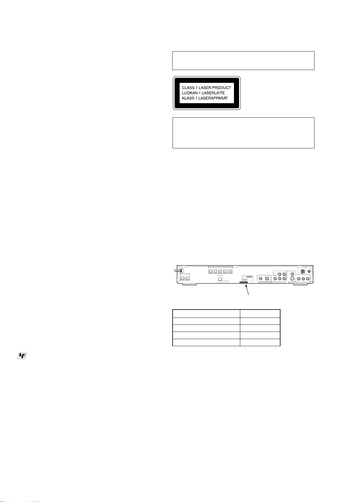
This appliance is classified as
a CLASS 1 LASER product.
This marking is located on
the rear exterior.
CAUTION
Use of controls or adjustments or performance of procedures
other than those specified herein may result in hazardous radiation
exposure.
Notes on chip component replacement
• Never reuse a disconnected chip component.
• Notice that the minus side of a tantalum capacitor may be
damaged by heat.
Flexible Circuit Board Repairing
• Keep the temperature of the soldering iron around 270 °C
during repairing.
• Do not touch the soldering iron on the same conductor of the
circuit board (within 3 times).
• Be careful not to apply force on the conductor when soldering
or unsoldering.
MODEL IDENTIFICATION
– Rear Panel –
SPEAKER
FRONT R
FRONT L SUR R SUR L
SPEAKER
WOOFERLWOOFER
R
CENTER
D-LIGHT SYNC OUT
(DVD ONLY)
DIGITAL IN
OUT
COAXIAL
SAT/CABLE
RLAUDIO IN
TV
(DVD ONLY)
YPB/CBPR/C
OPTICAL
COMPONENT VIDEO OUT
Parts No.
AM
VIDEO
S VIDEO
(DVD ONLY)
R
MONITOR OUT
SAT/CABLE
RLAUDIO INVIDEO IN
COAXIAL
FM75
UNLEADED SOLDER
Boards requiring use of unleaded solder are printed with the leadfree mark (LF) indicating the solder contains no lead.
(Caution: Some printed circuit boards may not come printed with
the lead free mark due to their particular size)
: LEAD FREE MARK
Unleaded solder has the following characteristics.
• Unleaded solder melts at a temperature about 40 °C higher
than ordinary solder.
Ordinary soldering irons can be used but the iron tip has to be
applied to the solder joint for a slightly longer time.
Soldering irons using a temperature regulator should be set to
about 350 °C.
Caution: The printed pattern (copper foil) may peel away if
the heated tip is applied for too long, so be careful!
• Strong viscosity
Unleaded solder is more viscou-s (sticky, less prone to flow)
than ordinary solder so use caution not to let solder bridges
occur such as on IC pins, etc.
• Usable with ordinary solder
It is best to use only unleaded solder but unleaded solder may
also be added to ordinary solder.
Model Part No.
SP model 3-197-464-5[]
E32 model 3-197-464-6[]
MX model 3-197-464-7[]
TH model 3-215-699-5[]
• Abbreviation
E32 : 110 – 240V AC area in E model
MX : Mexican model
SP : Singapore model
TH : Thai model
2
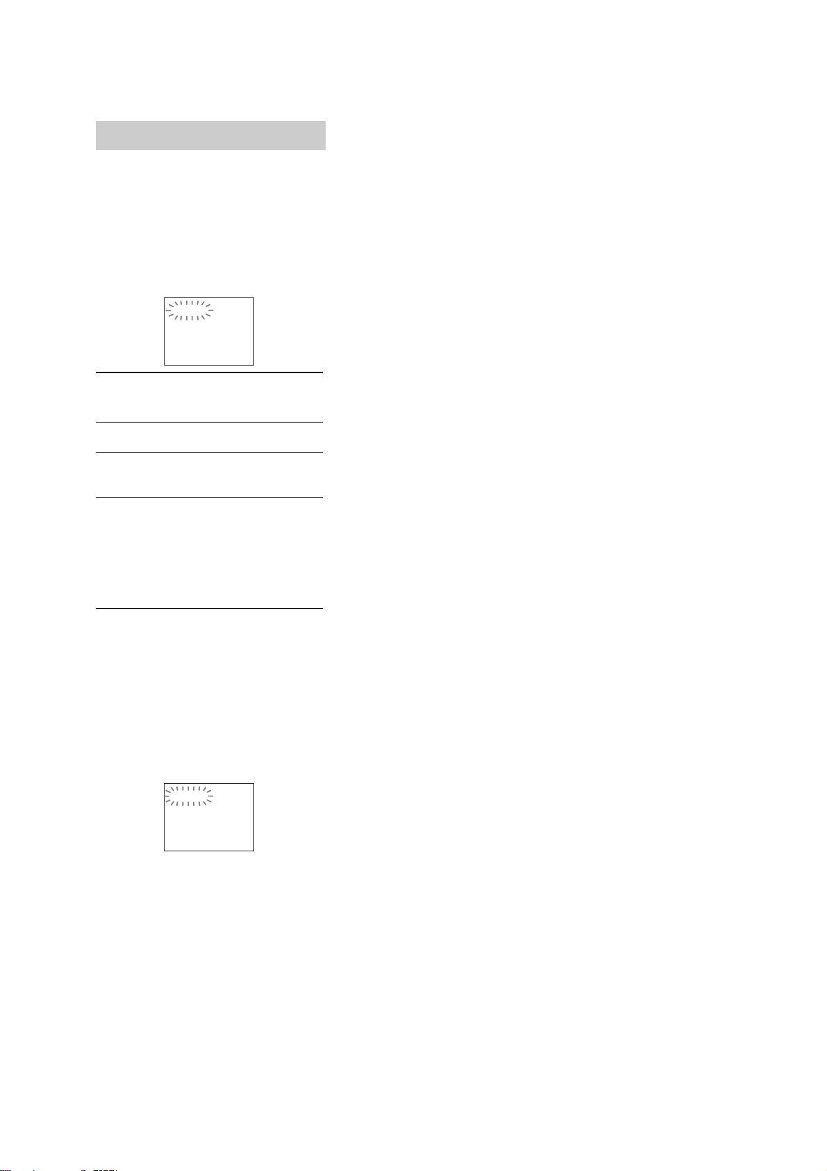
Self-diagnosis Function
(When letters/numbers appear in the
display)
When the self-diagnosis function is activated to
prevent the system from malfunctioning, a 5character service number (e.g., C 13 50) with a
combination of a letter and 4 digits appears on
the screen and the front panel display. In this
case, check the following table.
C:13:50
HCD-DZ7T
First 3
characters of
the service
number
C 13 The disc is dirty.
C 31 The disc is not inserted correctly.
E XX
(xx is a number)
Cause and/or corrective action
,Clean the disc with a soft cloth
,Restart the system, then re-insert
the disc correctly.
To prevent a malfunction, the
system has performed the selfdiagnosis function.
,Contact your nearest Sony
dealer or local authorized Sony
service facility and give the 5character service number.
Example: E 61 10
When displaying the version
number on the TV screen
When you turn on the system, the version
number [VER.X.XX] (X is a number) may
appear on the TV scree n. A lthough this is not a
malfunction and for Sony service us e only,
normal system operation will not be possible.
Turn off the sy stem, and t hen tu rn on th e sys tem
again to operate.
VER.X.XX
3

HCD-DZ7T
TABLE OF CONTENTS
1. SERVICING NOTE
................................................... 5
2. GENERAL ................................................................... 11
3. DISASSEMBLY
3-1. Disassembly Flow ........................................................... 14
3-2. Case (DS), Front Panel Assy ........................................... 15
3-3. FL Board.......................................................................... 16
3-4. JACK Board, P-SW Board .............................................. 17
3-5. Front Panel, Ornament .................................................... 17
3-6. Tuner (FM/AM)............................................................... 18
3-7. POWER Board ................................................................ 18
3-8. IO-S-OUT Board ............................................................. 19
3-9. SP Board, D.C. Fan ......................................................... 19
3-10. MAIN Board, DSP Board ............................................... 20
3-11. DVD Mechanism Deck (CDM85-DVBU102) ................ 21
3-12. Tray.................................................................................. 21
3-13. Belt, MS-203 Board ........................................................ 22
3-14. Optical Pick-up (KHM-313CAA) ................................... 23
4. TEST MODE ............................................................... 24
5. ELECTRICAL ADJUSTMENT ............................. 29
6. DIAGRAMS
6-1. Block Diagram – RF/VIDEO Section – ......................... 32
6-2. Block Diagram – AMP Section –................................... 33
6-3. Block Diagram – AUDIO Section – ............................... 34
6-4. Block Diagram – POWER Section –.............................. 35
6-5. Printed Wiring Board – MAIN Board (Side A) –........... 36
6-6. Printed Wiring Board – MAIN Board (Side B) – ........... 37
6-7. Schematic Diagram – MAIN Board (1/10) – ................. 38
6-8. Schematic Diagram – MAIN Board (2/10) – ................. 39
6-9. Schematic Diagram – MAIN Board (3/10) – ................. 40
6-10. Schematic Diagram – MAIN Board (4/10) – ................. 41
6-11. Schematic Diagram – MAIN Board (5/10) – ................. 42
6-12. Schematic Diagram – MAIN Board (6/10) – ................. 43
6-13. Schematic Diagram – MAIN Board (7/10) – ................. 44
6-14. Schematic Diagram – MAIN Board (8/10) – ................. 45
6-15. Schematic Diagram – MAIN Board (9/10) – ................. 46
6-16. Schematic Diagram – MAIN Board (10/10) – ............... 47
6-17. Printed Wiring Board – IO-S-OUT Board – .................. 48
6-18. Schematic Diagram – IO-S-OUT Board (1/2) – ............ 49
6-19. Schematic Diagram – IO-S-OUT Board (2/2) – ............ 50
6-20. Printed Wiring Board – DSP Board – ............................ 51
6-21. Schematic Diagram – DSP Board – ............................... 52
6-22. Printed Wiring Boards – FL, JACK Board – .................. 53
6-23. Schematic Diagram – FL Board – .................................. 54
6-24. Schematic Diagram – JACK Board – ............................. 55
6-25. Printed Wiring Boards – SP Board, P-SW Board – ....... 56
6-26. Schematic Diagram – SP Board, P-SW Board – ............ 56
6-27. Printed Wiring Board – MS-203 Board –....................... 57
6-28. Schematic Diagram – MS-203 Board – ......................... 57
6-29. Printed Wiring Board – POWER Board – ...................... 58
6-30. Schematic Diagram – POWER Board – ......................... 59
7. EXPLODED VIEWS
7-1. Overall Section ................................................................ 79
7-2. Front Panel Section ......................................................... 80
7-3. Chassis Section................................................................ 81
7-4. DVD Mechanism Deck Section (CDM85-DVBU102) ... 82
8. ELECTRICAL PARTS LIST .................................. 83
4
SECTION 1
SERVICING NOTE
HCD-DZ7T
NOTES ON HANDLING THE OPTICAL PICK-UP BLOCK
OR BASE UNIT
The laser diode in the optical pick-up block may suffer electrostatic
break-down because of the potential difference generated by the
charged electrostatic load, etc. on clothing and the human body.
During repair, pay attention to electrostatic break-down and also
use the procedure in the printed matter which is included in the
repair parts.
The flexible board is easily damaged and should be handled with
care.
NOTES ON LASER DIODE EMISSION CHECK
The laser beam on this model is concentrated so as to be focused on
the disc reflective surface by the objective lens in the optical pickup block. Therefore, when checking the laser diode emission,
observe from more than 30 cm away from the objective lens.
DISC TRA Y LOCK
The disc tray lock function for the antitheft of an demonstration
disc in the store is equipped.
Setting Procedure :
1. Press the ?/1 button to turn the set on.
2. Press the [FUNCTION] button to set DVD function.
3. Insert a disc.
4. Press the
x button and the A button simultaneously for fi v e
seconds.
5. The message “LOCKED” is displayed and the tray is locked.
Releasing Procedure :
1. Press the
x button and the A button simultaneously for fi v e
seconds again.
2. The message “UNLOCKED” is displayed and the tray is
unlocked.
Note: When “LOCKED” is displayed, the tray lock is not released by turning
power on/off with the ?/1 button.
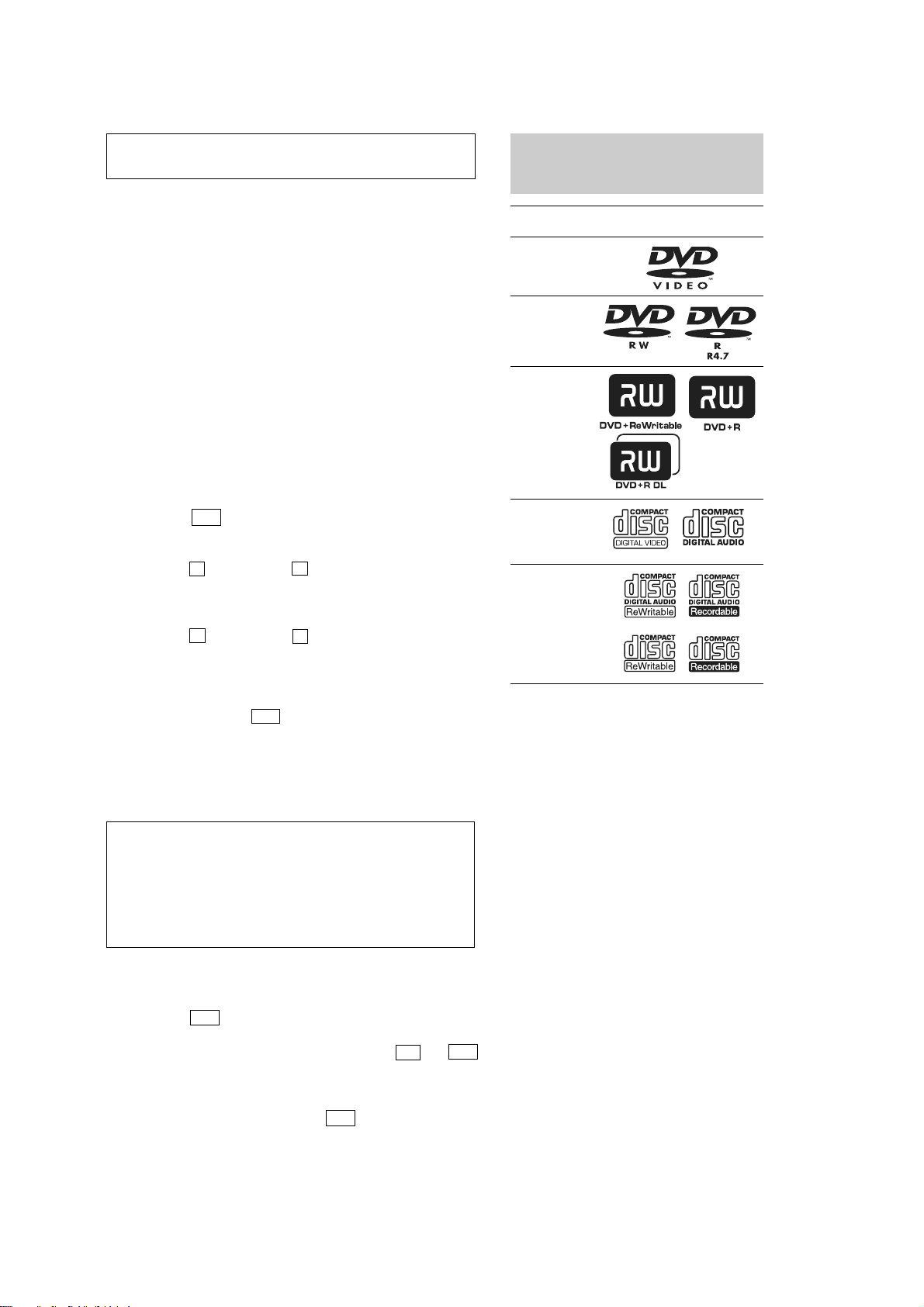
This System Can Play the
Following Discs
Format of
discs
DVD VIDEO
DVD-RW/
DVD-R
DVD+RW/
DVD+R
VIDEO CD
(Ver. 1.1 and
2.0 discs)/
Audio CD
CD-RW/CD-R
(audio data)
(MP3 files)
(JPEG files)
“DVD-RW,” “DVD+RW,” “DVD+R,”
“DVD VIDEO,” and the “CD” logos are trademarks.
Disc logo
On cleaning discs, disc/lens cleaners
• Do not use cleaning discs or disc/lens cleaners
(including wet or spray types). These may cause the apparatus
to malfunction.
IMPORTANT NOTICE
Caution: This system is capable of holding a still video image or
on-screen display image on your television screen indefinitely.
If you leave the still video image or on-screen display image
displayed on your TV for an extended period of time you risk
permanent damage to your television screen.
Projection televisions are especially susceptible to this.
Attention when transported
Use this mode when returning the set to the customer after repair.
Procedure:
1. Press the
?/1 button to turn the set on.
2. Press the [FUNCTION] button to set the function “DVD”.
3. Remove all discs, and then press two buttons
H and ?/1
simultaneously.
4. After a message “MECHA LOCK” is displayed on the
fluorescent indicator tube, pull out the AC plug.
5. To exit from this mode, press the
?/1 button to turn the set
on.
Note about CDs/DVDs
The system can play CD-ROMs/CD-Rs/CD-RWs recorded in the
following formats:
– audio CD format
– VIDEO CD format
– MP3 audio tracks, JPEG image files, and DivX video files of
format conforming to ISO 9660 Level 1/Lev el 2, or its extended
format, Joliet
The system can play DVD-ROMs/DVD+RWs/DVD-RWs/
DVD+Rs/DVD-Rs recorded in the following formats:
– MP3 audio tracks, JPEG image files, and DivX video files of
format conforming to UDF (Universal Disc Format)
Example of discs that the system cannot play
The system cannot play the following discs:
• CD-ROMs/CD-Rs/CD-RWs other than those recorded in the
formats listed on “Note about CDs/DVDs”
• CD-R OMs recorded in PHOTO CD format
• Data part of CD-Extras
• DVD Audios
• Super Audio CD
• DATA DVDs that do not contain MP3 audio tracks, JPEG
image files, or DivX video files
• DVD-RAMs
Also, the system cannot play the following discs:
• A DVD VIDEO with a different region code
• A disc that has a non-standard shape (e.g., card, heart)
• A disc with paper or stickers on it
• A disc that has the adhesive of cellophane tape or a sticker
still left on it
5
HCD-DZ7T
Notes about CD-R/CD-RW/DVD-R/DVD-RW/DVD+R/
DVD+RW
In some cases, CD-R/CD-RW/DVD-R/DVD-RW/DVD+R/
DVD+RW cannot be played on this system due to the recording
quality or physical condition of the disc, or the characteristics of
the recording device and authoring software.
The disc will not play if it has not been correctly finalized. For
more information, see the operating instructions for the recording
device.
Note that some playback functions may not work with some
DVD+R Ws/D VD+Rs, even if they ha ve been correctly finalized. In
this case, view the disc by normal playback. Also some DATA CDs/
DATA DVDs created in Packet Write format cannot be played.
Copyrights
This product incorporates copyright protection technology that is
protected by U.S. patents and other intellectual property rights. Use
of this copyright protection technology must be authorized by
Macrovision, and is intended for home and other limited viewing
uses only unless otherwise authorized by Macrovision. Reverse
engineering or disassembly is prohibited.
This system incorporates with Dolby* Digital and Dolby Pro Logic
(II) adaptive matrix surround decoder and the DTS** Digital
Surround System.
* Manufactured under license from Dolby Laboratories.
“Dolby”, “Pro Logic”, and the double-D symbol are
trademarks of Dolby Laboratories.
** Manufactured under license from DTS, Inc.
“DTS” and “DTS Digital Surround” are registered trademarks
of DTS, Inc.
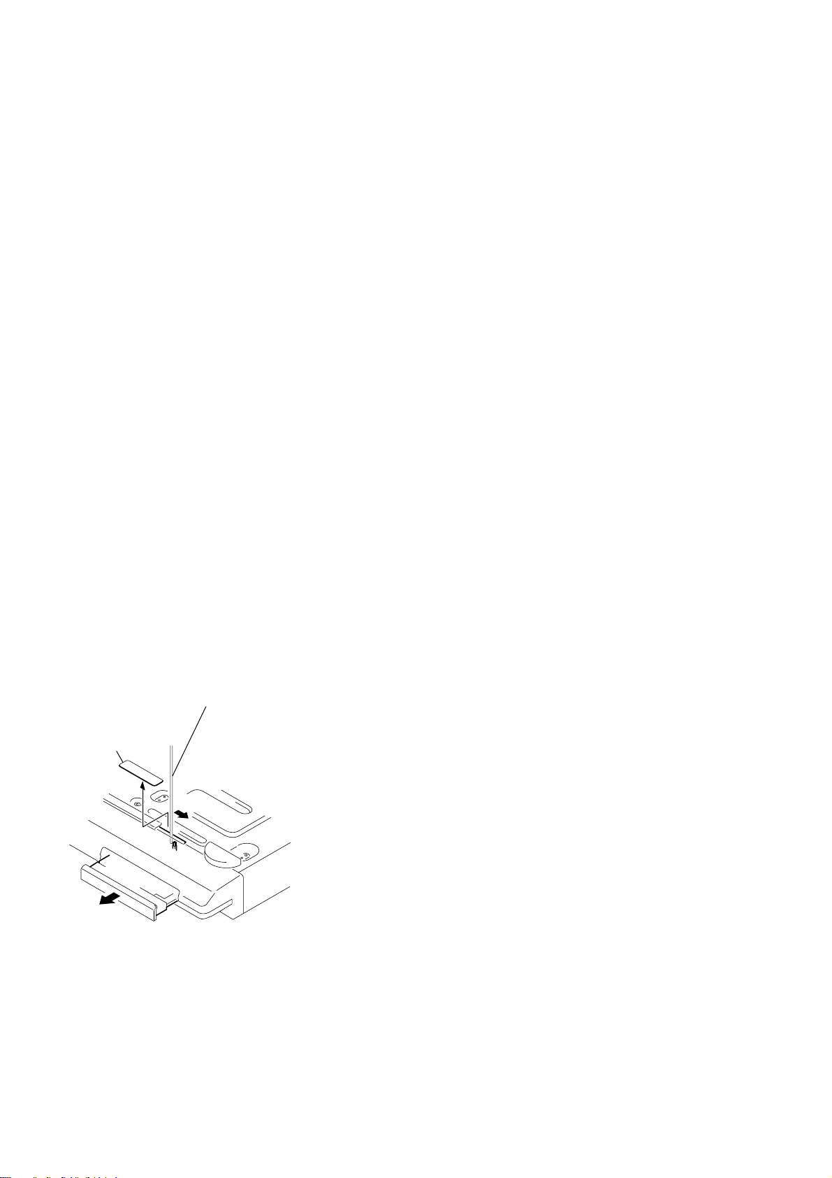
How to open the disc table when power switch turns off
Insert a tapering driver into the aperture of the unit bottom, and slide it in the direction of the arrow.
Peel off the seal and so the lever is moved
in the direction of the arrow with the thin rod.
seal
disc tray
6
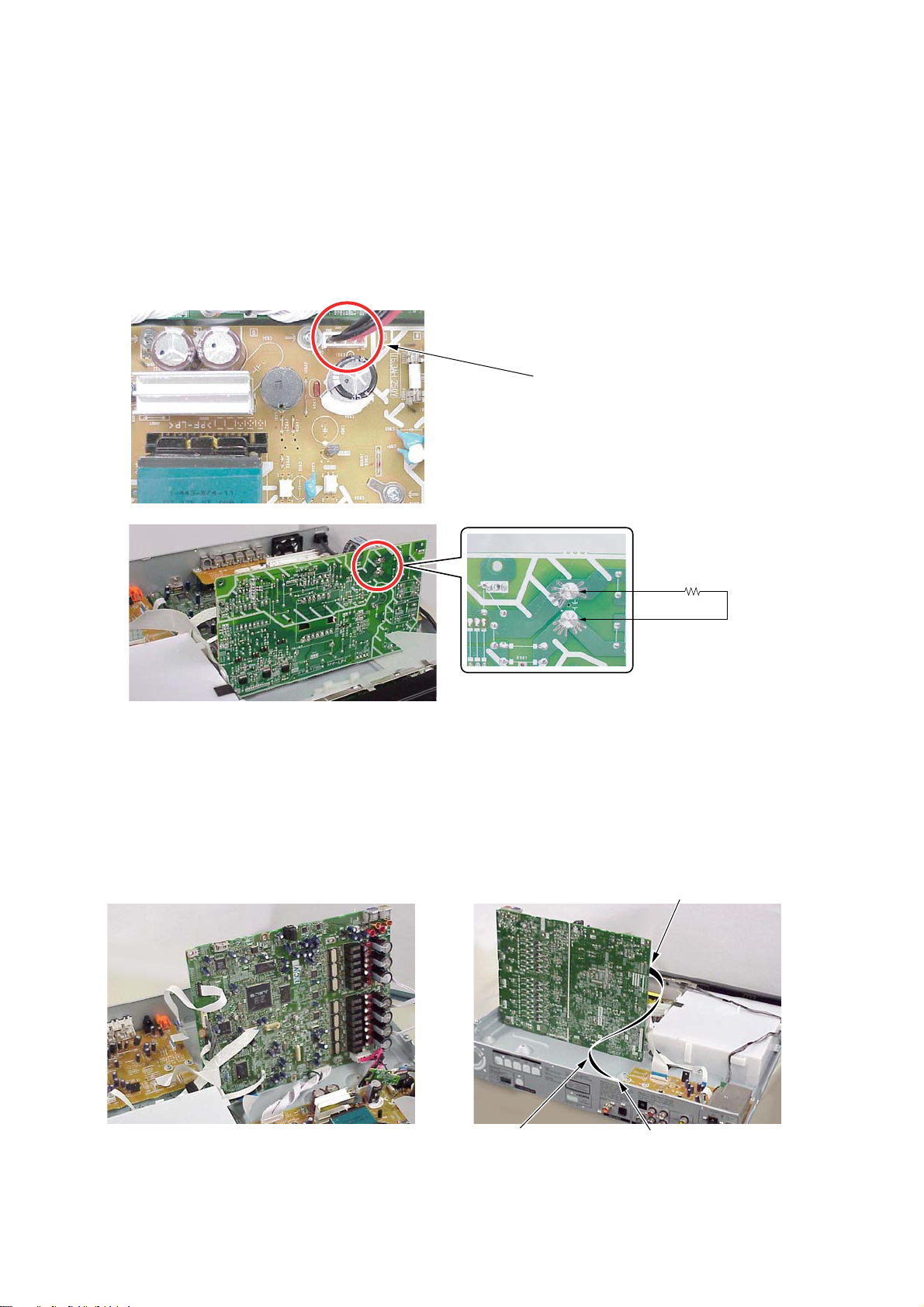
Discharge the charged electricity in capacitors to prevent electric shock as follows
When disassembling the machine, be sure to discharge the charged electricity in the following capacitors.
Use a resistor of 800 ohms, 2 Watts for discharging the following capacitors.
HCD-DZ7T
Ver. 1.1
POWER board
C903: 440 V (EXCEPT MX) / 240 V (MX)
C932, C933, C934, CN904: 30 V
MAIN board
CN3002: 30 V
• Abbreviation
MX : Mexican model
Point of capacitor discharge for C932, C933, C934:
Connect to the red and black wire of CN904
800
Ω
/2W
Point of capacitor discharge for C903:
Connect to the foot of CN903
MAIN board service position
Please take the above-mentioned position in the repair of MAIN board.
In that case, it is necessary the following extension cable during CN304 on IO-S-OUT board and CN4302 on MAIN board .
CN4302
MAIN board service position
jig
jig P/N: J-2501-242-A
(pitch 1.00 mm/11p/length 300 mm)
CN304
7
HCD-DZ7T
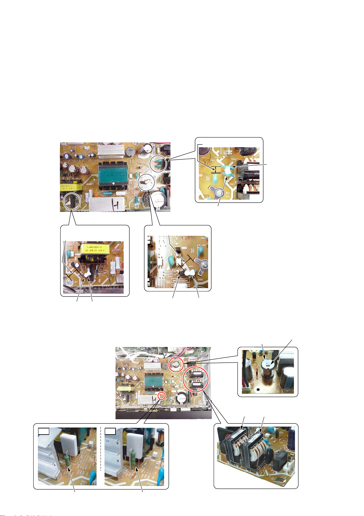
e
Parts that require fixing using adhesive agent
The following parts on the POWER board must be fixed by using the adhesive agent (such as Sony Bond Master) as it is specified by Safety
Regulations. When any part or printed circuit board is replaced during repair work, be sure to confirm that the following capacitors and resistors
are fixed by using the adhesive agent (such as Sony Bond Master) without fail.
POWER board: • C924 and R927 (refer to below fig.)
• C913 (Push down to C903 side and so fix.)
• C910 and C930 (refer to below fig.)
• EB905 side of C903
• EB905 side of C934
• C964 and C963 (refer to below fig.)
• Space between C933 and C932
• C908 and Q901 (Don’t touch IC901.)
POWER BOARD
OK:more than 8mm
NG:less than 8mm
Don't incline C924 to outside.
OK:more than 8mm
NG:less than 8mm
OK:more than 3.5mm
NG:less than 3.5mm
C964
C963
C924 R927
C910
C930
Attention of the direction at replacement
Please defend and install the direction of the below fig in the following parts on the POWER board.
POWER BOARD
OK NG
L931
LF902 LF901
mark this sid
R912 R912
8
HCD-DZ7T
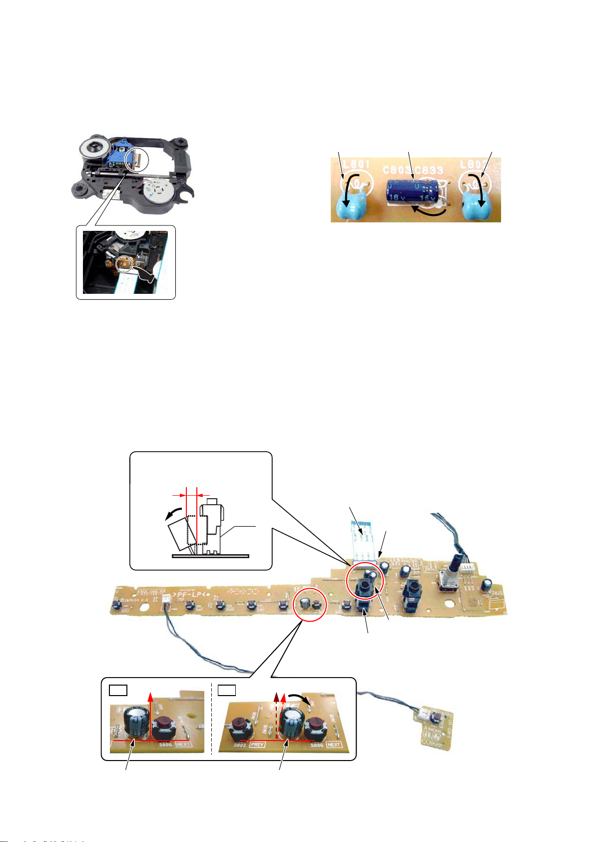
Precaution when installing a new OP unit /
Precaution before unsoldering the static electricity
prevention solder bridge
When installing a new OP unit, be sure to connect the flexible
printed circuit board first of all before removing the static
electricity prevention solder bridge by unsoldering.
Remove the static electricity prevention solder bridge by
unsoldering after the flexible printed circuit board has already
been connected.
(Do not remove nor unsolder the solder bridge as long as the
OP unit is kept standalone.)
Note on replacement of C803, C802, L801,
and L802
Please fold in the directtion of the arrow and set up at
replacement of C803, C802, L801, and L802 on FL board.
L801 L802C803
+
–
Note on C471 and C411 on JACK board
Bend C411 and keep the distance as shown. (Fig.-1)
Confirm C471 standing straightly. (Fig.-2)
Distance between the C411
top and bottom:
OK: 2 mm ± 1 mm
J401
C411
Fig.-1
Fig.-2
OK NG
JACK board
TERMINAL side
J401
CN806
C411
JACK BOARD
C471 C471
P-SW BOARD
9

HCD-DZ7T
The wire (12P) that ties CN906 (POWER board) to CN506 (MAIN board)
Twist 1.5 circles and connect to CN906 fix wire 12P with LP as shown below.
(Must keep wire 12P away from the HEAT SINK, and can not touch it.)
LP501
CN906
10
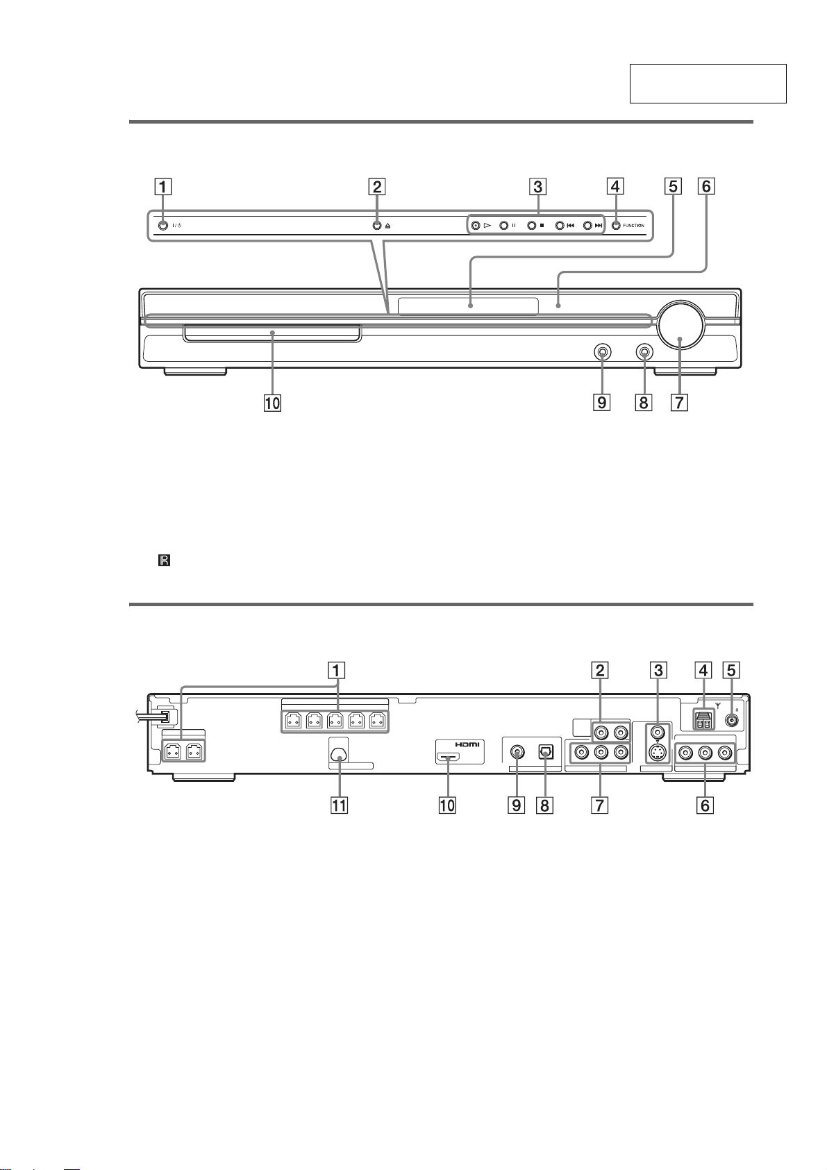
Front panel
SECTION 2
GENERAL
HCD-DZ7T
This section is extracted
from instruction manual.
A "/1 (on/standby) (26)
B A (open/close) (26)
C Disc operation (26)
D FUNCTION (26)
E Front panel display (100)
F (remote sensor) (8)
Rear panel
FRONT
FRONT
R
L
SPEAKER
WOOFERRWOOFER
L
SPEAKER
SURRSUR
CENTER
D-LIGHT SYNC OUT
G VOLUME control (26)
H MIC 2 jack (62)
I AUDIO IN/MIC 1/A.CAL MIC jack (15, 24,
62)
J Disc tray (26)
COAXIAL
AM
RLAUDIO INVIDEO IN
SAT/CABLE
FM75
L
DIGITAL IN
OUT
(DVD ONLY)
COAXIAL
SAT/CABLE
OPTICAL
RLAUDIO IN
TV
(DVD ONLY)
YPB/CBPR/C
COMPONENT VIDEO OUT
R
VIDEO
S VIDEO
(DVD ONLY)
MONITOR OUT
A SPEAKER jacks (9)
B TV (AUDIO IN R/L) jacks (9)
C MONITOR OUT (S VIDEO/VIDEO) jacks
(20)
D AM terminal (9)
E COAXIAL FM 75Ω jack (9)
F SAT/CABLE (AUDIO IN R/L, VIDEO IN)
jacks (24)
G COMPONENT VIDEO OUT jacks (20)
H SAT/CABLE (DIGITAL IN OPTICAL)
jack (24)
I SAT/CABLE (DIGITAL IN COAXIAL)
jack (24)
J HDMI OUT jack (20)
K D-LIGHT SYNC OUT jack (24)
11
HCD-DZ7T
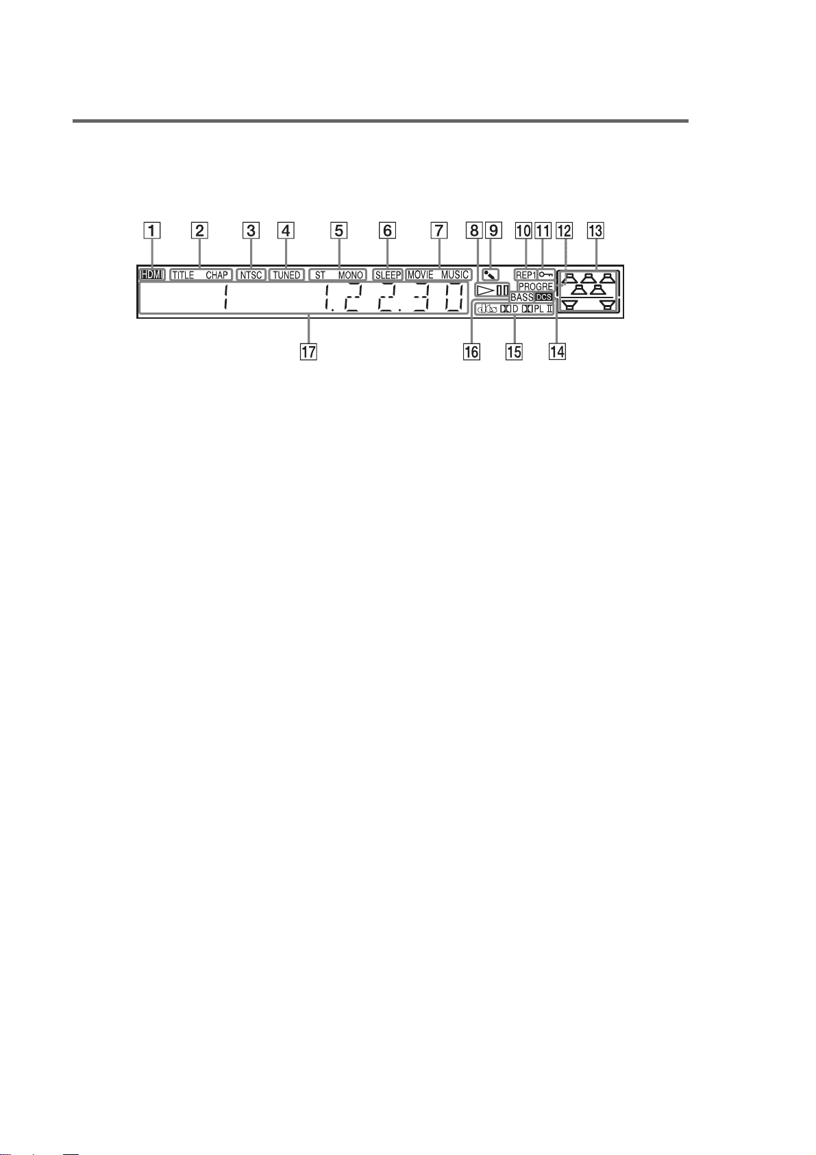
Front panel display
About the indications in the front panel display
A Lights up when the HDMI OUT jack is
correctly connected to HDCP (highbandwidth digital content protection)
compliant device with HDMI or DVI
(digital visual interface) input. (20)
B Lights up when the time information of
a title or chapter appears in the front
panel display. (DVD only) (43)
C Lights up when the color system is set
to NTSC. (Asian models only)
D Lights up when a station is received.
(Radio only) (56)
E Stereo/Monau ral effect (Radio only)
(57)
F Lights up when the sleep timer is set.
(66)
G Lights up when the movie or music
mode is selected. (29)
H Playing status (DVD fu nct ion only)
I Lights up when the karaoke mode is
on. (62)
J Current repeat mode (39)
K Lights up when the child lock fu nct ion
is set to on. (68)
L Lights up when the system outputs
progressive signals (DVD function
only). (22)
M Indicates the selected [SPEAKER
FORMATION]. (72)
N Lights up when Digital Cinema Sound
(DCS) is activated. (30)
O Current surround format (Except for
JPEG)
P Lights up when the DYNAMIC BASS is
selected. (66)
Q Displays system’s status such as
chapter, title, or track number, time
information, radio frequency, pl aying
status, sound field, etc.
12
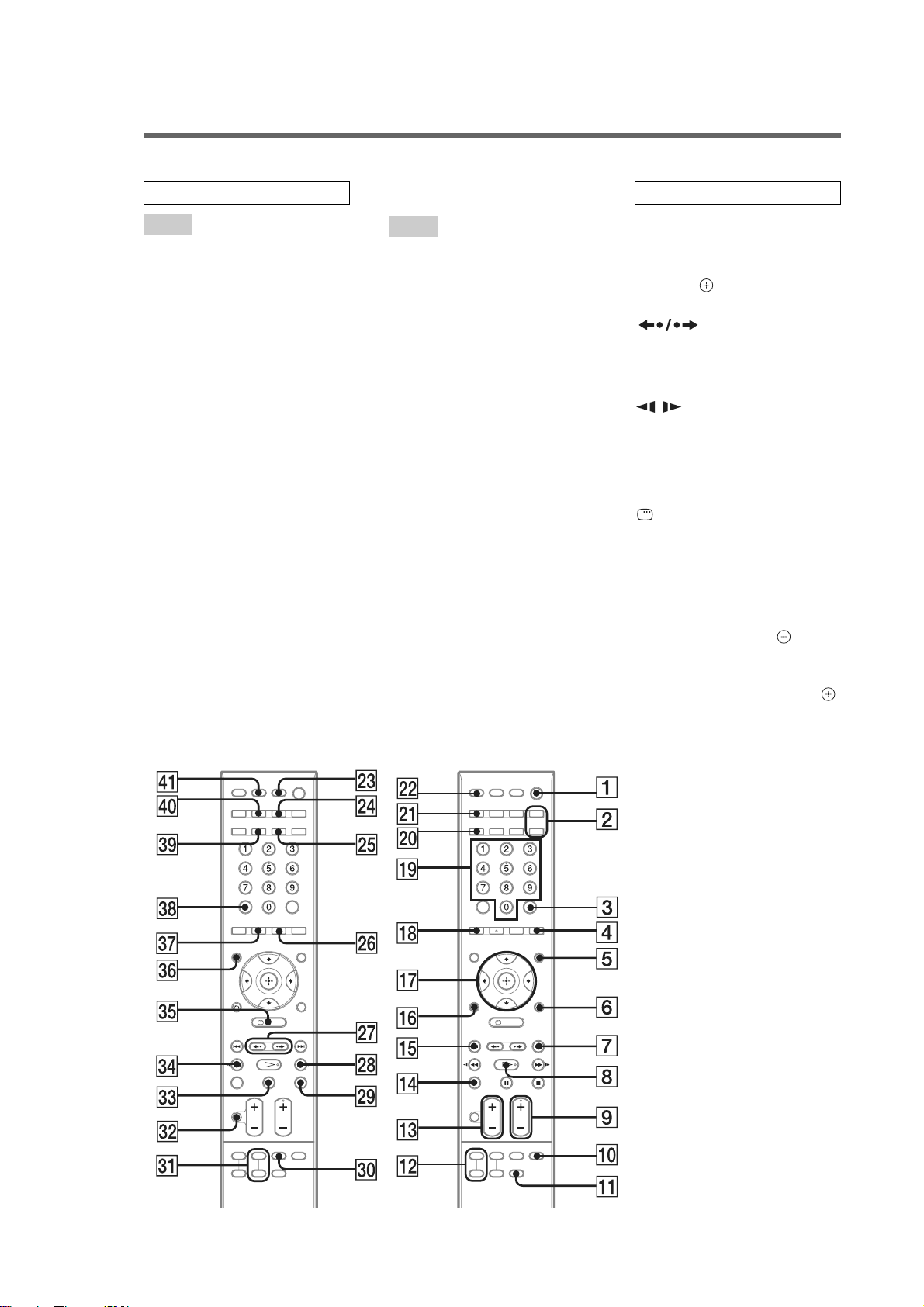
R
emote control
A
A
C
D
D
D
D
D
E
E
F
K
K
M
M
M
N
,
,
.
e
HCD-DZ7T
ALPHABETICAL ORDER
A – O
NGLE 4 (45)
UDIO** ej (40)
LEAR ek (34, 58, 60, 77)
.TUNING wh (57)
ISPLAY wf (43, 58)
VD MENU 5 (40, 53)
VD TOP MENU eh (40)
YNAMIC BASS wg (66)
CHO qa (62)
NTER* 3 (15, 18, 28, 34, 56,
69)
UNCTION +/– 2 (22, 26, 28,
35, 56, 72)
ARAOKE PON 0 (64)
EYCON #/b ea (63)
IC VOL +/– qs (62)
OVIE/MUSIC el (29)
UTING es (26)
umber buttons** ql (34, 57, 59,
69)
P – Z
PICTURE NAVI qk (35, 60)
PRESET +/– 7 qg (57)
SCORE e; (65)
SLEEP r; (66)
SOUND FIELD +/–** 9 (30)
SUBTITLE wh (46)
SYSTEM MENU 6 (18, 28, 67,
105)
THEATRE SYNC wd (61)
TOOLS 6 (59)
TUNING +/– wk ef (56)
TV qf (59)
TV CH +/–** 9 ( 59)
TV INPUT wa (59)
TV MENU eg (59)
TV VOL +/– qd (59)
VIDEO FORMAT w; (22)
VOLUME +/–
qd (26, 57, 84)
BUTTON DESCRIPTIONS
[/1 (on/standby) 1 (15, 18, 26
35, 57)
TV [/1 (on/standb y) ra (59)
C/X/x/c/
56, 69)
ADVANCE wj (26)
./> qg 7 (26)
m/M ef wk (33)
/ ef wk (33)
H (play)** 8 (26, 35, 70)
x (stop) wl (27, 35, 69)
X (pause) ed (27)
Z (open/close) ws (27)
DISPLAY eg (17, 34, 69,
101)
O RETURN
-/-- ek (60)
* The ENTER butt on ha s the
same function as the button
When you operate the TV, th
ENTER button is used for
selecting a chan nel, an d the
button is used for selec ting
menu items ( p age 59) .
**The H, number 5, AUDIO,
and SOUND FIELD + (TV CH
+) buttons have tactile dots.
Use the tactil e dots as
references when operating the
system.
qj (15, 18, 28, 34
REPLAY/
qh (35)
13
HCD-DZ7T
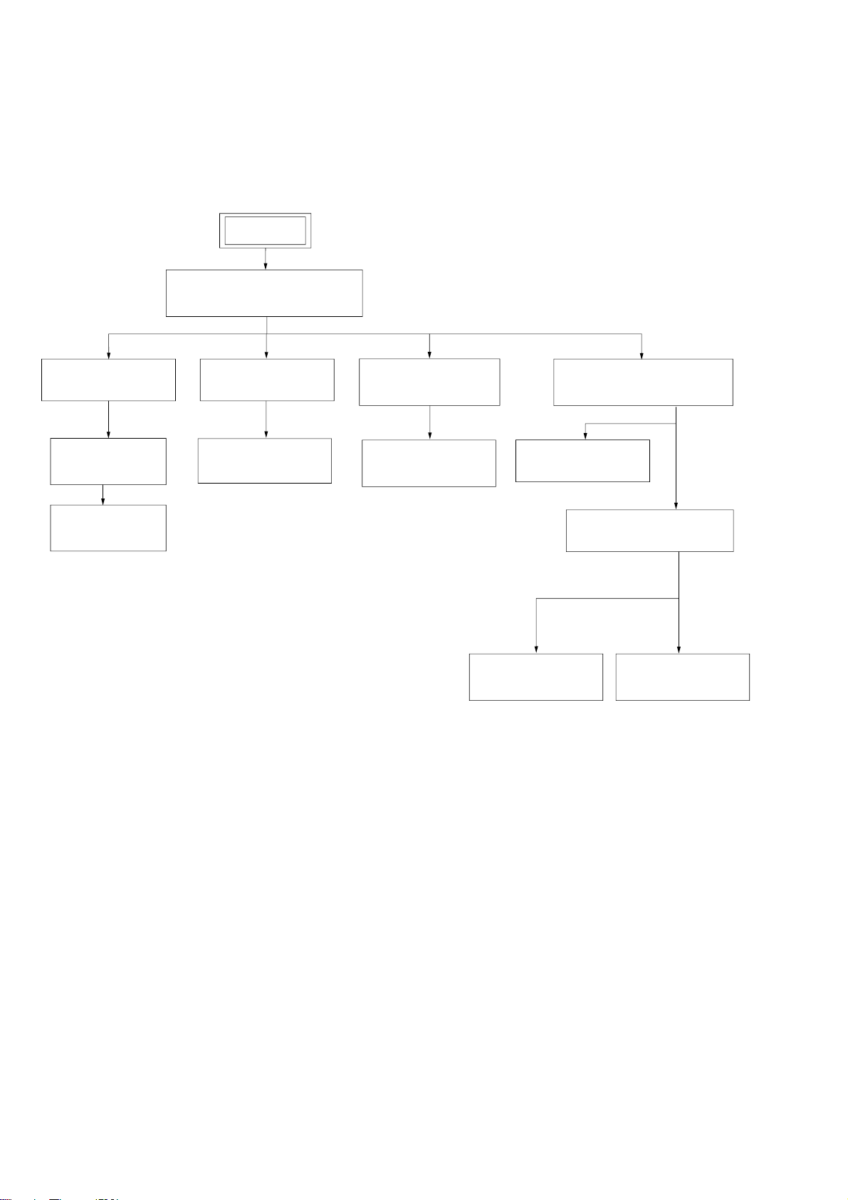
3-1. DISASSEMBLY FLOW
• This set can be disassembled in the order shown below.
SET
3-2. CASE (DS),
FRONT PANEL ASSY
(Page 15)
SECTION 3
DISASSEMBLY
3-3. FL BOARD
(Page 16)
3-4. JACK BOARD,
P-SW BOARD
(Page 17)
3-5. FRONT PANEL,
ORNAMENT
(Page 17)
3-6. TUNER (FM/AM)
(Page 18)
3-8. IO-S-OUT BOARD
(Page 19)
3-9. SP BOARD,
D.C. FAN
(Page 19)
3-10. MAIN BOARD,
DSP BOARD
(Page 20)
3-11. DVD MECHANISM DECK
3-7. POWER BOARD
(Page 18)
3-14. OPTICAL PICK-UP
(KHM-313CAA)
(Page 23)
(CDM85-DVBU102)
(Page 21)
3-12. TRAY
(Page 21)
3-13. BELT,
MS-203 BOARD
(Page 22)
14
Note: Follow the disassembly procedure in the numerical order given.
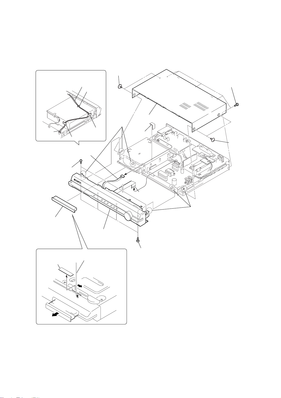
3-2. CASE (DS), FRONT PANEL ASSY
5
two screws
Route the harness as shown below.
(CASE 3
×
8 TP2)
HCD-DZ7T
lead pin
qa
qd
two
(+BVTP
4
loading panel
harness
notch
rib
connector 5P (CN302)
screws
2.6 × 10
)
rib
qf
three
claws
8
case (DS)
9
unweaved
cloth
q;
21core (CN502)
w
ire (flat type)
qg
three claws
7
five screws
(+BVTP 3 × 8)
6
two screws
(CASE 3 × 8 TP2)
2
The lever is moved in the direction
of the arrow with the thin rod.
1
seal
3
qh
front panel assy
qs
four screws
(+BV 3 × 6)
15
HCD-DZ7T
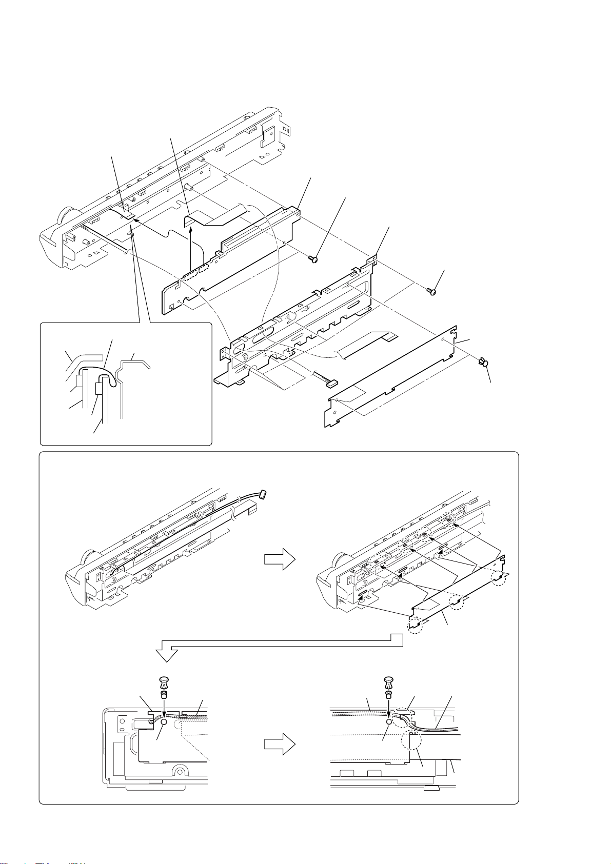
3-3. FL BOARD
6
wire (flat type)
13core (CN805)
7
wire (flat type)
21core (CN801)
8
FL board
5
two
screws
(+BVTP 2.6
×
10)
4
shield plate (FR)
3
five
screws
(+BVTP 2.6
×
10)
wire (flat type) 13core
front panel
CN806
JACK
CN805
board
FL board
shield plate (FR)
Route the wire
(flat type) 13core
as shown in the figure.
PRECAUTION DURING THE RETAINER (DS) INSTALLATION
(1) Assemble seven claws securely.
retainer (DS)
2
retainer (DS)
1
two
rivets
16
(2) Route the harness as shown below. (3) Route the harness as shown below.
retainer (DS)
rivet rivet
harness
hole
retainer (DS)
hole
groove
groove
harness
wire (flat type)
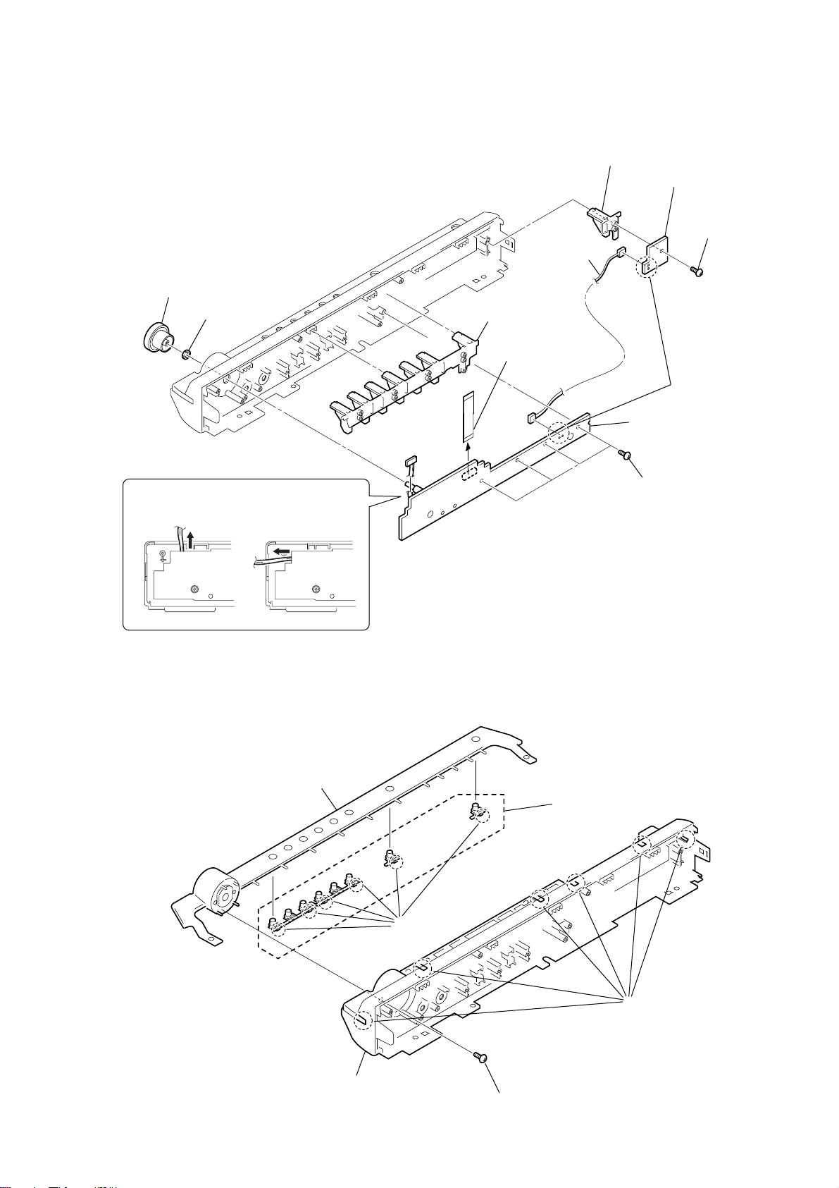
3-4. JACK BOARD, P-SW BOARD
1
knob (vol)
2
nut
4
button (base)
5
wire (flat type)
13core (CN806)
9
7
harness
button (base)
q;
qa
JACK board
HCD-DZ7T
P-
SW board
6
screw
(+BVTP
8
Remove the
solderings.
2.6 × 10
)
Route the harness as shown below.
(NG)(OK)
JACK board JACK board
3-5. FRONT PANEL, ORNAMENT
6
ornament
5
button (cap)
3
four
(+BVTP
screws
2.6 × 10
)
3
front panel
4
six
claws
1
screw
(+BVTP
2.6 × 10
2
six
claws
)
17
HCD-DZ7T
3-6. TUNER (FM/AM)
3
tuner (FM/AM)
2
wire (flat type) 9core
1
two
(+BVTT
screws
2.6 × 6
)
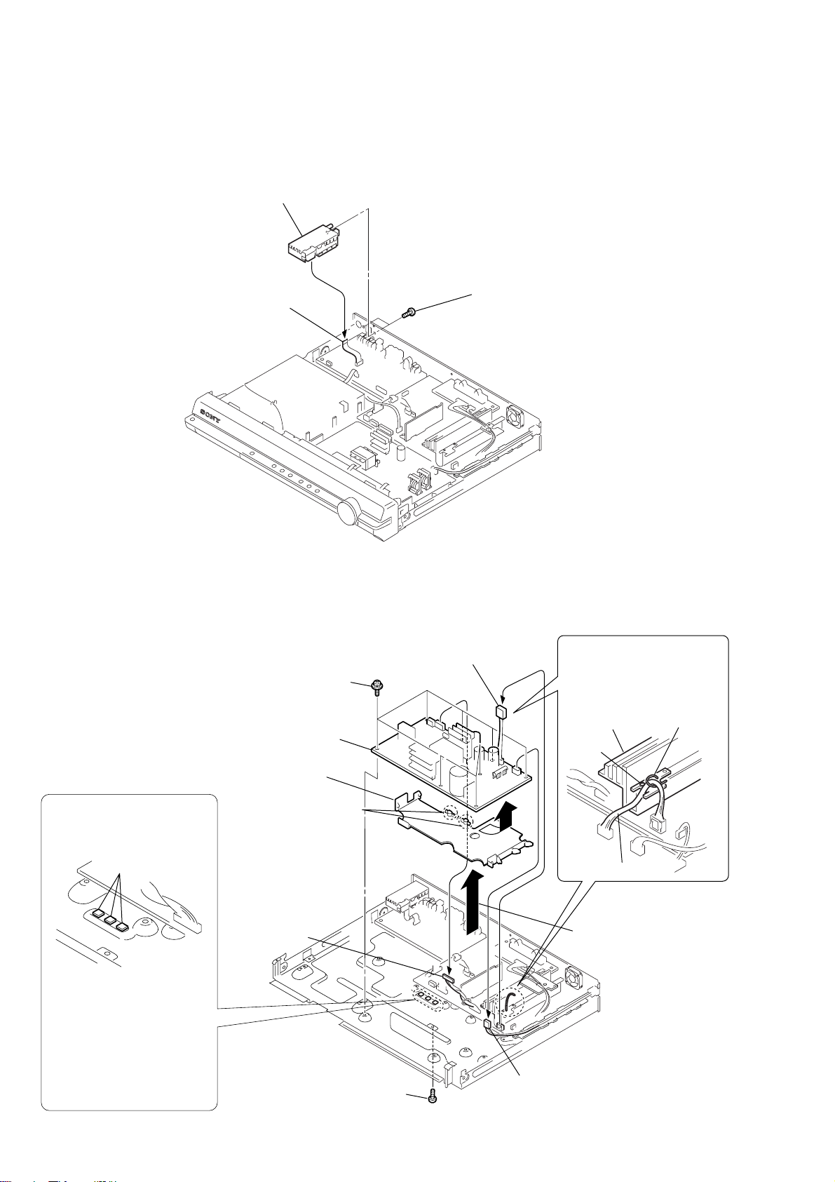
3-7. POWER BOARD
Attach the heat radiation sheets
on the chassis, and then install
the POWER board.
radiation sheets
Attention at assembling
POWER board.
Because of prevention of
damage caused by creep of
radiation sheets, outfit a power
board with the set after fitting
the cover (PWB) on the POWER
board.
5
eight screws
(+PWH 3
9
POWER board
8
cover (PWB)
7
Remove the two claws
in the direction of the
B
arrow
3
connector
12p (CN906)
.
×
8)
4
screw
(+BV 3
1
connector
4p (CN3002)
×
6)
A
B
2
connector
2p (CN901)
Clamp the harnesses with a
lead pin or a similar tool so
that they do not touch this
screw and the heatsink (AMP).
heatsink (AMP)
screw
harness
6
Remove the POWER board
and the cover (PWB) in the
direction of the arrow
lead pin
A
.
18
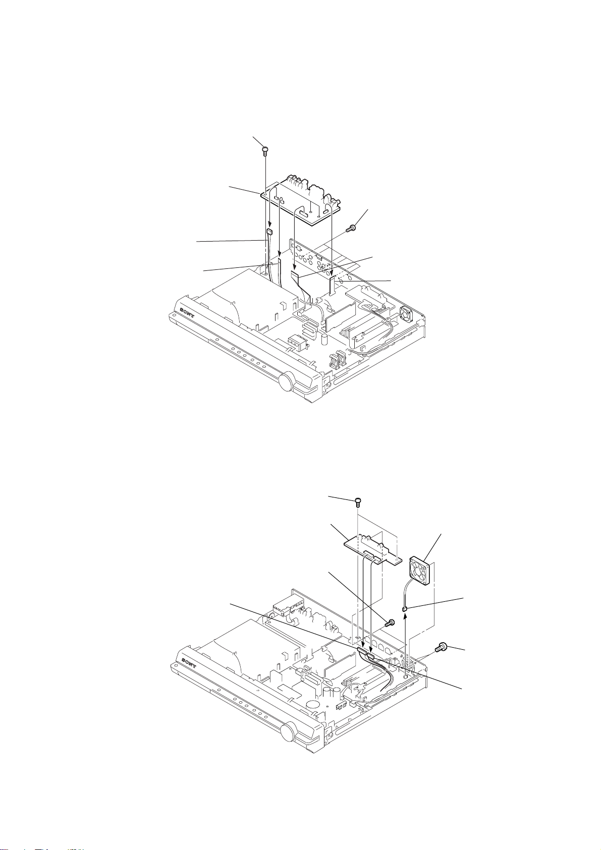
3-8. IO-S-OUT BOARD
)
7
IO-S-OUT board
4
connector
5p (CN302)
3
wire (flat type)
5core (CN307)
6
three
(+BV
screws
3 × 6
HCD-DZ7T
)
5
six
screws
3 × 8
(+BVTP
2
wire (flat type) 21core (CN311)
1
)
wire (flat type)
11core (CN304)
3-9. SP BOARD, D.C. FAN
1
connector
6p (CN304)
4
two
screws
(+BV
5
SP board
3
two screws
(+BVTP
3 × 6
)
3 × 8
8
D.C. fan
)
6
connector
2p (CN3000)
7
two screws
(+BVTT
4 × 8
2
connector
4p (CN303)
19
HCD-DZ7T
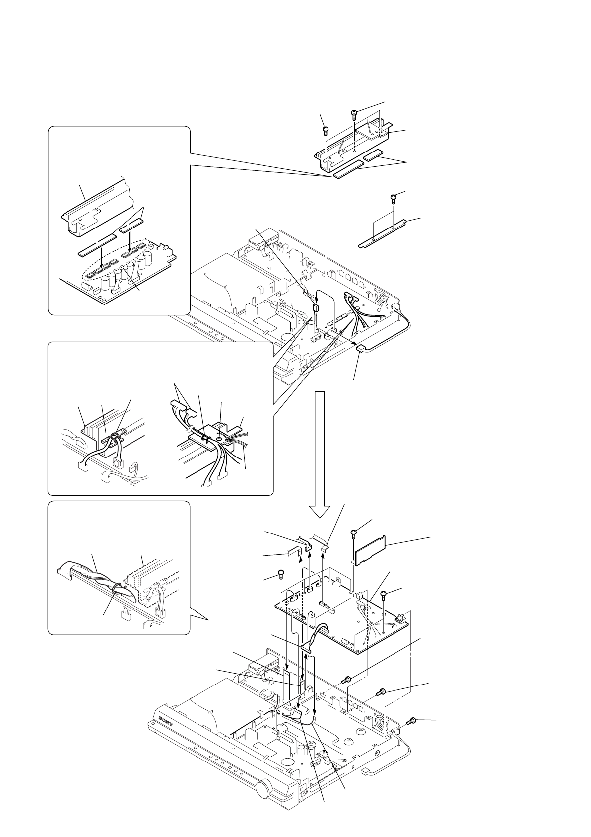
3-10. MAIN BOARD, DSP BOARD
Attaching the two radiation sheets
on the IC MAIN board first, and then
attach the heatsink (AMP).
heatsink (AMP)
radiation
sheets
IC on the
MAIN board
Clamp the harnesses with a lead pin or a similar tool so that
they do not touch this screw and the heatsink (AMP).
harness
heatsink
(AMP)
harness
lead pin
lead pin
1
connector
4p (CN3002)
screw
heatsink
(AMP)
5
two screws (+BV 3 × 10)
2
connector
2p (CN901)
6
screw (+BVTP 3 × 12)
7
heatsink (AMP),
HEATSINK B board,
HEATSINK A board
8
two radiation sheets
3
three
screws (+BV 3 × 6)
4
INSULATOR
board
Clamp the harness with a lead pin
or a similar tool so that they do not
touch the heatsink (AMP).
harness
heatsink (AMP)
lead pin
qd
wire (flat type) 21core (CN604)
qf
wire (flat type) 11core (CN4302)
0
connector
6p (CN1201)
qa
wire (flat type)
5core (CN1202)
w;
four
screws
(+BV 3
qs
connector
12p (CN906)
harness
(D.C. fan)
×
6)
9
wire (flat type) 24core (CN1101)
wa
screw
×
wf
MAIN board
wd
6)
ws
two
screws
(+BV 3
ql
screw
(+B 3
qk
qj
(+BV 3
DSP board
×
6)
×
6)
screw
(+BVTP 3
screw
(+BVTP 3
×
8)
×
8)
20
qh
wire (flat type) 5core (CN702)
qg
wire (flat type) 21core (CN502)
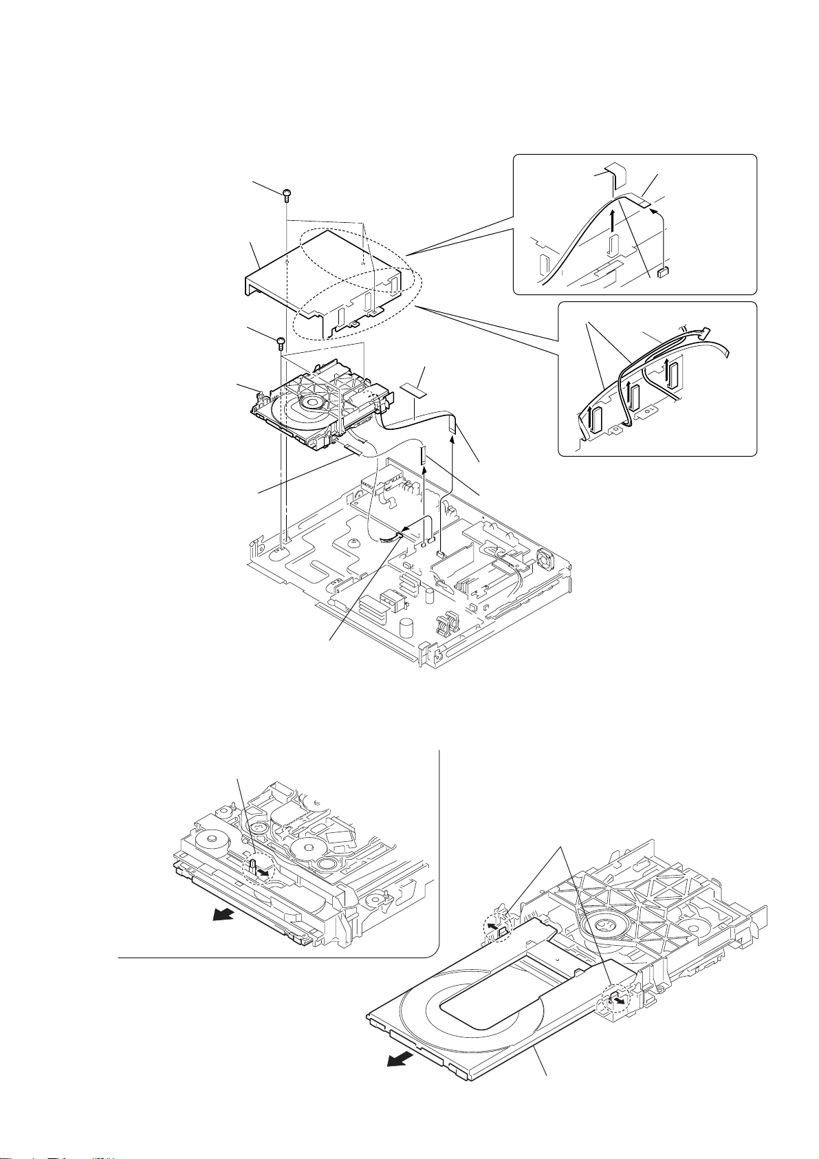
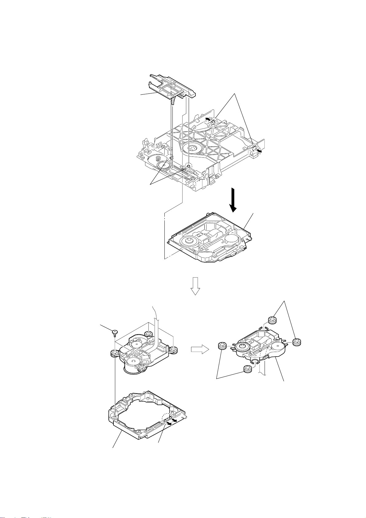
3-11. DVD MECHANISM DECK (CDM85-DVBU102)
9
three
screws (+BV 3 × 6)
q;
cover (MD)
qa
three
screws (+BV 3 × 6)
qd
DVD mechanism deck
(CDM85-DVBU102)
4
unweaved
cloth
2
unweaved
cloth
HCD-DZ7T
1
wire (flat type)
5core (CN307)
3
Remove the wire.
8
Remove the wire and harnesses.
qs
wire (flat type) 5core
3-12. TRAY
1
Move the chuck cam
in the direction of the arrow.
7
connector 6p (CN1201)
bottom side
5
wire (flat type) 24core
(CN1101)
6
wire (flat type) 5core
(CN1202)
two claws
3
2
4
5
tray
21
HCD-DZ7T
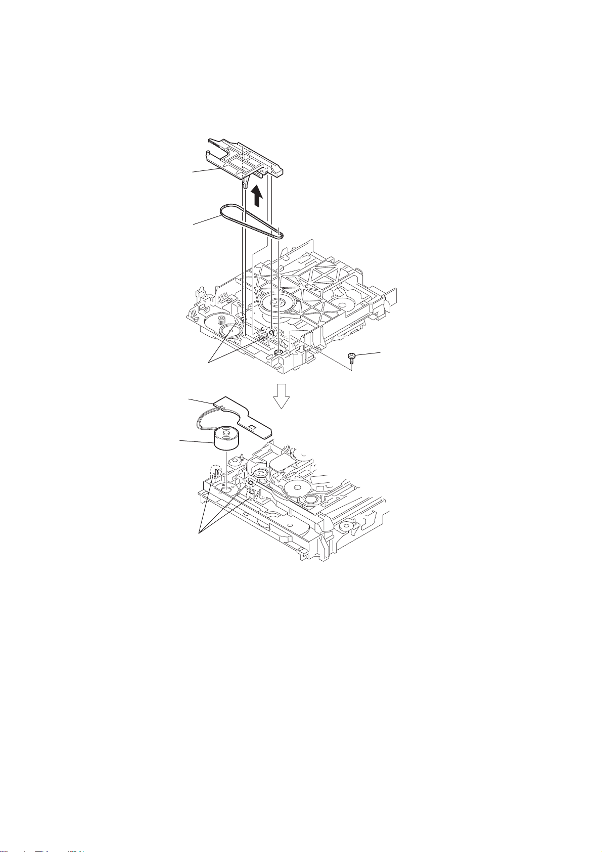
3-13. BELT, MS-203 BOARD
2
chuck cam
3
belt
7
MS-203 board
6
DC motor
1
two claws
5
three claws
4
screw
(M 1.7 × 2.5)
22
3-14. OPTICAL PICK-UP (KHM-313CAA)
2
chuck cam
1
two claws
3
two claws
HCD-DZ7T
6
four insulator screws
9
two insulators
4
base unit
0
(KHM-313CAA)
8
two insulators
optical pick-up
7
bu holder
5
two claws
23
HCD-DZ7T
SECTION 4
TEST MODE
Note: Incorrect operations may be performed if the test mode is not
entered properly.
In this case, press the ?/1 button to turn the power off, and retry
to enter the test mode.
1. Cold Reset
• The cold reset clears all data including preset data stored in
the RAM to initial conditions. Execute this mode when
returning the set to the customers.
Procedure:
1. Press the ?/1 button to turn the power on.
2. Press three buttons x , A and ?/1 simultaneously.
3. When this button is operated, display as “COLD RESET” for
a while and all of the settings are reset.
2. Panel Test Mode
• This mode is used to check the software version, FL and KEY.
2-1. Display Test Mode
Procedure:
1. Press the ?/1 button to turn the power on.
2. Press three buttons X , . and A simultaneously.
3. When the display test mode is activated, all segments are turned
on.
4. To e xit from this mode, press three b uttons X , . and A
simultaneously.
2-2. V ersion T est Mode
Procedure:
1. When the display test mode is activated, press the . button
and the message “BS5K” is displayed, the version test mode is
activated.
2. Whenever the . button is pressed, the display changes in
the following order.
“BS5K” (Model name) t “ASIA2*1” (Destination) t MC t SYS
CEC T CLA T TM T DSP T TA T ST T DVD T UI
*1: ASIA2 changes depending on destination.
3. Press the > button and the date of the software production
is displayed.
4. Press the > button again and the version is displayed.
5. To e xit from this mode, press three b uttons X , . and A
simultaneously.
2-3. Key Test Mode
Procedure:
1. When the display test mode is activated, press the H button,
to select the key test mode.
2. To enter the KEY test mode, the f luorescent indicator displays
“K0 V0”. Each time an another button is pressed, “KEY” v alue
increases. However, once a button is pressed, it is no longer
taken into account. When all keys are pressed correctly, “K8
V0” is displayed.
3. When the V OLUME control is turned in the direction of (+),
“V0” is changed to “V1”, then ... “V9”.
When the V OLUME control is turned in the direction of (–),
“V0” is changed to “V9”, then ... “V1”.
4. To e xit from this mode, press three b uttons X , . and A
simultaneously.
3. Disc Tray Lock
The disc tray lock function for the antitheft of an demonstration
disc in the store is equipped.
Setting Procedure :
1. Press the ?/1 button to turn the power on.
2. Press the FUNCTION button to set DVD function.
3. Insert a disc.
4. Press the x button and the A button simultaneously for fi ve
seconds.
5. The message “LOCKED” is displayed and the tray is locked.
Releasing Procedure :
1. Press the x button and the A button simultaneously for fi ve
seconds again.
2. The message “UNLOCKED” is displayed and the tray is
unlocked.
Note: When “LOCKED” is displayed, the tray lock is not released by turning
power on/off with the ?/1 button.
4. DVD Ship Mode
Use this mode when returning the set to the customer after repair.
Procedure:
1. Press the ?/1 button to turn the power on.
2. Press the FUNCTION button to set the function “DVD”.
3. Remove all discs, and then press two buttons H and ?/1
simultaneously.
4. After a message “MECHA LOCK” is displayed on the
fluorescent indicator tube, pull out the AC plug.
5. To exit from this mode, press the ?/1 button to turn the set
on.
5. AM Step Change
• A step of AM channels can be changed over between 9 kHz
and 10 kHz.
Procedure:
1. Press the ?/1 button to turn the power on.
2. Select the function “TUNER”, and press FUNCTION button
to select “TUNER AM”.
3. Press the ?/1 button to turn the power off.
4. Press two buttons > and ?/1 simultaneously, and the
display of fluorescent indicator tube changes to “ AM 9k STEP”
or “ AM 10k STEP”, and thus the channel step is changed over .
6. Product Out
This mode moves the optical pick-up to the position durable to
vibration and clears all data including preset data stored in the RAM
to initial conditions. Use this mode when returning the set to the
customer after repair.
Procedure:
1. Press the ?/1 button to turn the power on.
2. Press the FUNCTION button to set the function “DVD”.
3.
Remove all discs, and then
?/1 simultaneously.
4. After the “ST ANDBY” blinking display finishes, the message
“MECHA LOCK” is displayed on the fluorescent indicator
tube disconnect the A C po wer plug, then the ship mode is set.
7. Demo Play Out
It is a mode to release the demonstration reproduct by the dedicated
demonstration disc.
Setting Procedure:
1. Press the ?/1 button to turn the power on.
2. Press the FUNCTION button to set the function “DVD”.
3. During playback the DEMO Disc, press the x and H
buttons for five seconds simultaneously.
4. The message “DEMO OFF” is displayed, a mode to reproduct
the demonstration is released.
press three buttons > , A and
24
HCD-DZ7T
Ver. 1.1
8. V olume Test
Procedure:
1. Press the
?/1 button to turn the power on.
2. Press three buttons . , H and > simultaneously.
3. The message “ MEASURE” is displayed.
4. When the V OLUME control is turned in the direction of (+),
the message “VOLUME MAX” is displayed.
5. When the V OLUME control is turned in the direction of (–),
the message “VOLUME MIN” is displayed.
6. Press the MUTING button on the remote commander.
7. The message “VOL N” is displayed and VOLUME control
is normal.
8. Press the MUTING button on the remote commander again.
9. The message “VOL M/N” is displayed and VOLUME control
is “MAX” and “MIN”.
10. To exit from this mode, press the
?/1 button to turn the set
off, the message “COLD RESET” is displayed.
9. Protection Factor (SD Detection/DC Detection)
Identification Test Mode
When an error is detected, the FL tube alternately displays
“PROTECTOR h PUSH POWER”.
Press the
r
* Buttons other than the
?/1 button.
?/1 button are invalid.
“STANDBY” blinks three times on the FL tube.
r
The protection release state (POWER OFF) is established.
(No FL tube display)
r Press the ?/1 button.
The power to the system turns on, and the normal operation is
established. (Restore)
During the protection state:
1. If the AC plug is connected or disconnected during the
protection state, the protection state is released, and the normal
operation is established. (The protection state is not
maintained.)
2. The protection factor is displayed by pressing the
FUNCTION , A and > buttons at the same time during
the protection state
(during the “PRO TECTOR h PUSH POWER” display).
k When SD is detected: Repeats
“SD DETECT h PUSH POWER”.
k When DC is detected: Repeats
“DC DETECT h PUSH POWER”.
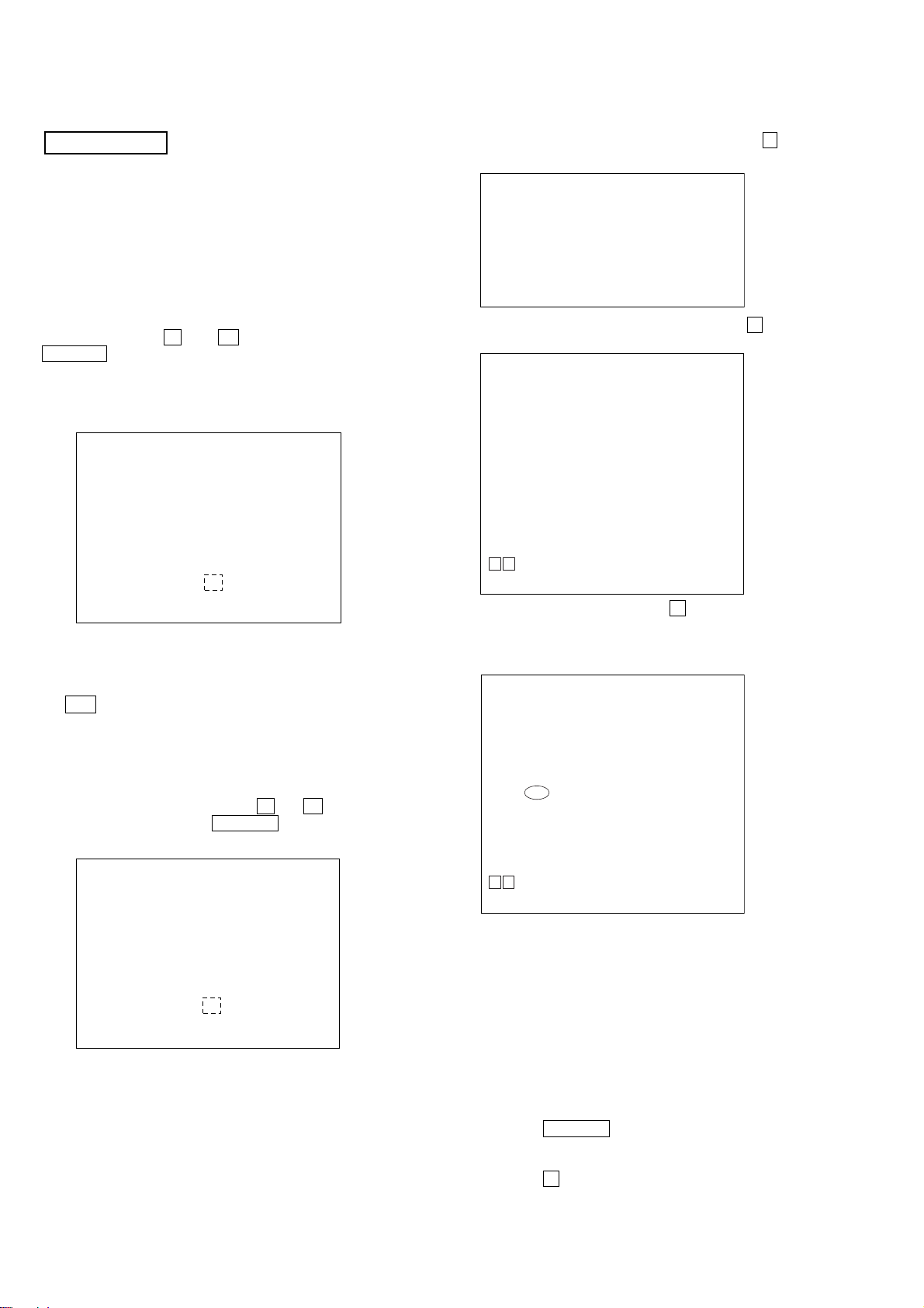
10. Automatic Acoustic Field Calibration Microphone
Test Mode
Procedure:
1. Press the ?/1 button to turn the power on.
2. Press the FUNCTION button to set the function “ DVD”.
3. While pressing the X and A buttons simultaneously, turn
the VOLUME control in the direction of (+) .
4. Insert ECM-AC2 supplied as an accessory into the AUDIO
IN/MIC 1/A.CAL MIC jack.
5. Confirm that the following are shown on the display panel.
1 The JACK inserted/non-inserted detection display and the
STEREO/MONO detection display.
Content of display Discriminant state
NON Not detected
ST STEREO
MN MONO
* * *J A C K
1
6. To exit from this mode, press the ?/1 button to turn the
power off.
11. Color System Change-over
(Singapore and Thai models)
It is a mode to switch the color system (PAL/NTSC).
Procedure:
1. Press the ?/1 button to turn the power on
2. Press the FUNCTION button to set the function “DVD”.
3. Press the ?/1 button to turn the power off.
4. While pressing the X button, press the ?/1 button
simultaneously.
5. Each time you perform this operation the color system toggles
between P AL and NTSC. “NTSC” lights up in the front display
when “NTSC” is selected.
PL: SD detection
When the “L” output from the SD (shutdown) port on the SMASTER POWER Driv er is detected, the power system other
than that of the FL tube is turned off, and the protection state
is established.
DC detection
When the “L” output from the power/speaker error detection
circuit (DC detection port) is detected for two seconds
continually, the po wer system other than that of the FL tube is
turned off, and the protection state is established.
25
HCD-DZ7T
DVD SECTION
12-1. General Description
The IOP measurement allows you to make diagnosis and adjustment
simply by using the remote commander and monitor TV. The
instructions, diagnosis results, etc. are given on the on-screen display
(OSD).
Be sure to execute the IOP measurement when a BU (Base Unit) is
replaced.
12-2. How To Enter Test Mode
While pressing the
VOLUME control in the direction of (+) with the DVD player in
power on.
The Test Mode starts, displayed “SERVICE IN” on this model
display then the menu shown below will be displayed on the TV
screen.
0. External Chip Check
1. Servo Parameter Check
2. Drive Manual Operation
3. Emergency History
4. Version Information
Model Name
IF-con : V
Syscon : Ver.
*1: Changes depending on destination
The menu above is the Remocon Diagnosis Menu screen which
consists of five main functions. At the bottom of the menu screen, the
model name and IF-con version. To exit from the Test Mode, press
the ?/1 button on the remote commander.
12-3. Executing IOP Measurement
In order to execute IOP measurement, the following standard
procedures must be followed.
(1) In power on, while pressing the
simultaneously, turn the VOLUME control in the direction
of (+).
0. External Chip Check
1. Servo Parameter Check
2. Drive Manual Operation
3. Emergency History
4. Version information
Model Name
IF-con : Ver. XX.XX (XXXX)
Syscon : Ver. X.XXX
*1: Changes depending on destination
x and A buttons simultaneously, turn
Remocon Diagnosis Menu
1
X.XXX
*
x and A buttons
1
*
: BS5K_ XX
er. XX.XX (XXXX)
Remocon Diagnosis Menu
: BS5K_ XX
(2) Select “2. Driv e Manual Operation” by pressing the 2 button
on the remote commander. The screen will appear as shown.
Drive Manual Operation
1. Servo Control
2. Track/Layer Jump
3. Manual Adjustment
4. Tray Aging Mode
5. MIRR time adjust
0. Return to Top Menu
(3) Select “3. Manual Adjustment” by pressing the 3 button on
the remote commander. The screen will appear as shown.
Manual Adjust
1. Track Balance Adjust:
2. Track Gain Adjust:
3. Focus Balance Adjust:
4. Focus Gain Adjust:
5. Eq Boost Adjust:
6. Iop:
7. TRV. Level:
8. S curve(FE) Level:
9. RFL(PI) Level:
0. MIRR Time:
Oo Change Value
[RETURN] Return to previous menu
(4)Select “6.IOP” by pressing the 6 button on the remote
commander.
(5) Wait until a hexadecimal number appear.
Manual Adjust
1. Track Balance Adjust:
2. Track Gain Adjust:
3. Focus Balance Adjust:
4. Focus Gain Adjust:
5. Eq Boost Adjust:
6. Iop. 52:
7. TRV. Level:
8. S curve(FE) Level:
9. RFL(PI) Level:
0. MIRR Time:
Oo Change Value
[RETURN] Return to previous menu
(6) Convert each data from hexadecimal to decimal using
conversion table.
(7) Please find the label on the rear of the BU (Base Unit).
The default IOP value is written in the label.
(8) Subtract between these two values.
(9) If the remainder is smaller than 93 (decimal), then it is OK.
However if the v alue is higher than 93, then the BU is defecti ve
and need to be change.
26
(10) Press the RETURN button on the remote commander to
return back to previous menu.
(11) Press the 0 button on the remote commander to return to
Top Menu.
HCD-DZ7T
12-4. Emergency History
To check the emergency history, please follow the following
procedure.
(1) From the Top Menu of Remocon Diagnosis Menu, select “3.
Emergency History Check” by pressing the 3 button on the
remote commander. The following screen appears on the onscreen display.
Emg. History Check
Laser Hours CD 999h 59min
01. 01 05 04 04
00 00 00 00 00 00 23 45
02. 02 02 01 01 00 A9 4B 00
00 00 00 00 00 00 23 45
[Next] Next Page [Prev] Prev Page
[O] Return to Top Menu
DVD 999h 59min
00 92 46 00
(2) You can check the total time w hen the laser is turned on during
playback of DVD and CD from the abov e menu. The maximum
time, which can be displayed are 999h 59min.
(3) You can check the error code of latest 10 emergency history
from the above menu. To view the previous or next page of
emergency history , press . or > button on the remote
commander. The error code consists of the following three
blocks. The first block indicates the error code. The second
block indicates the parameter and the third block indicates the
time of error code as shown below.
52: Open kick spindle error
51: Spindle stop error
60: Focus on error
61: Seek fail error
62: Read Q data/ID error
70: Lead in data read fail
71: TOC read time out (CD)
80: Can’t buffering
81: Unknown media type
12-4-1. Clear the Laser Hour
Press
DISPLAY button and then press CLEAR button on the
remote commander. The data for both CD and DVD data are reset.
Emg. History Check
Laser Hours CD 0h 0min
01. 01 05 04 04
00 00 00 00 00 00 23 45
02. 02 02 01 01 00 A9 4B 00
00 00 00 00 00 00 23 45
[Next] Next Page [Prev] Prev Page
[O] Return to Top Menu
DVD 0h 0min
00 92 46 00
12-4-2. Clear the Emergency History
Press DVD T OP MENU button and then press CLEAR button on
the remote commander. The error code for all emergency history
would be reset.
• Error Code
Emg. History Check
Laser Hours CD 999h 59min
*1*
01. 01 05 04 04
02. 02 02 01 01 00 A9 4B 00
[O] Return to Top Menu
2
00 00 00 00 00 00 23 45
00 00 00 00 00 00 23 45
[Next] Next Page [Prev] Prev Page
DVD 999h 59min
00 92 46 00
*1 : Error Code
*2 : Parameter of error code
*3 : Time of error code
The meaning of error code is as below:
01: Communication error (No reply from syscon)
02: Syscon hung up
03: Power OFF request when syscon hung up
19: Thermal shutdown
24: MoveSledHome error
25: Mechanical move error (5 Changer)
26: Mechanical move stack error
30: DC motor adjustment error
31: DPD offset adjustment error
32: TE balance adjustment error
33: TE sensor adjustment error
34: TE loop gain adjustment error
35: FE loop gain adjustment error
36: Bad jitter after adjustment
40: Focus NG
42: Focus layer jump NG
Emg. History Check
Laser Hours CD 999h 59min
01. 00 00 00 00
00 00 00 00 00 00 00 00
*
3
02. 00 00 00 00 00 00 00 00
00 00 00 00 00 00 00 00
[Next] Next Page [Prev] Prev Page
[O] Return to Top Menu
DVD 999h 59min
00 00 00 00
12-4-3. Clear the Initialize Setup Data
Press DVD MENU button and then press CLEAR button on the
remote commander.
Emg. History Check
Laser Hours CD 999h 59min
Initialize setup data...
[Next] Next Page [Prev] Prev Page
[O] Return to Top Menu
DVD 999h 59min
27

HCD-DZ7T
12-4-4. Return to the Top Menu of Remocon Diagnosis
Menu
Press 0 button on the remote commander.
• Check Version Information
To check the version information, please follow the following
procedure.
(1) From the Top Menu of Remocon Diagnosis Menu, select “4.
Version Information” by pressing the 4 button on the remote
commander. The following screen appears on the on-screen
display.
Version information
Firm (Main) : Ver. x.xxx
Firm (Sub) : xx.xx
RISC : xxxxxx
8032 : xxxxxx
Audio DSP : xx.xx.xx.xx
Servo DSP : xx.xx.xx.xx
[O] Return to Top Menu
T o return to the T op Menu of Remocon Diagnosis Menu, press
0 button on the remote commander.
28
SECTION 5
ELECTRICAL ADJUSTMENT
DVD SECTION
When the optical pick-up assy is replaced, perform the “Executing
IOP Measurement”.
Executing IOP Measurement (See page 26)
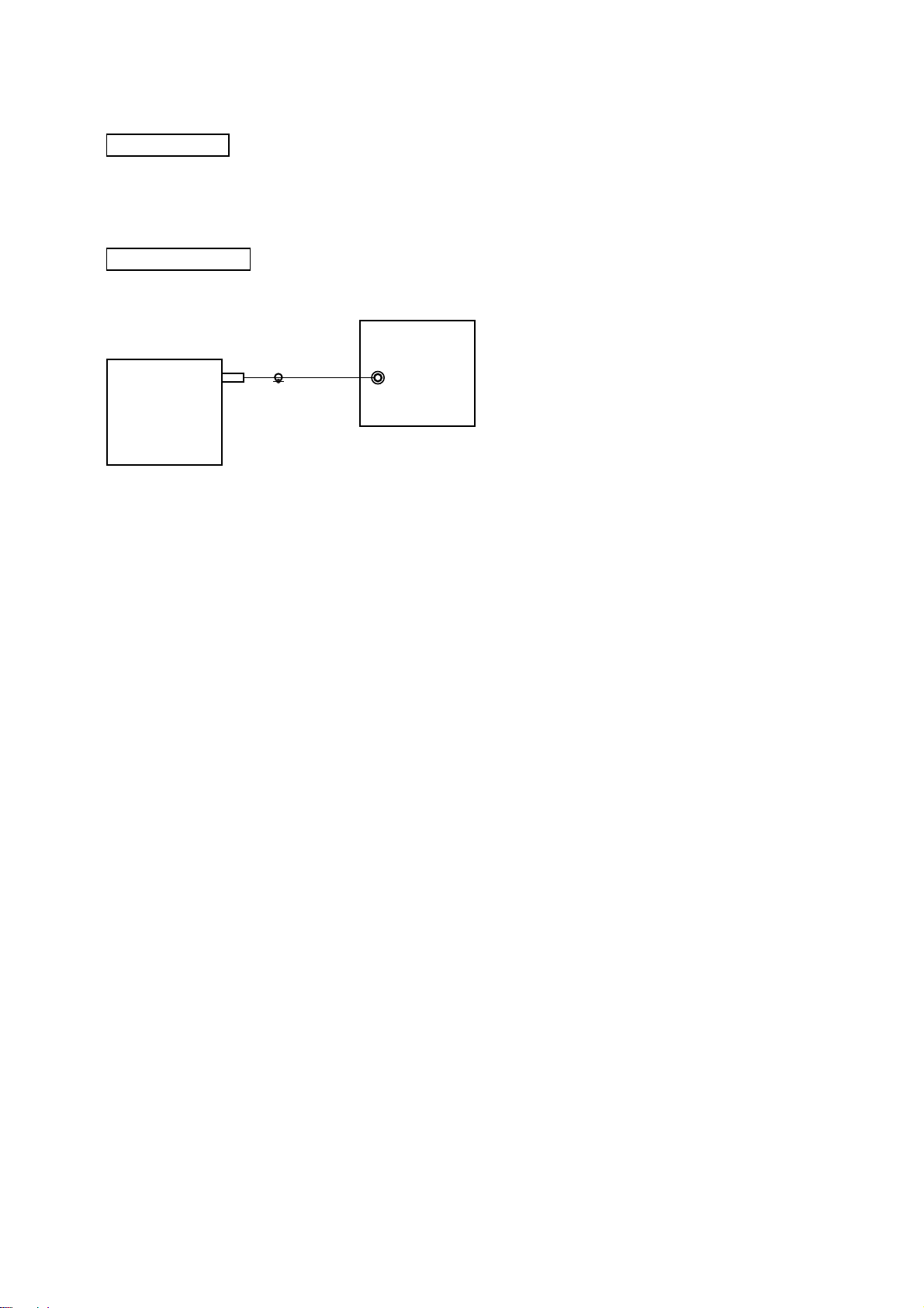
TUNER SECTION
[FM Tune Level Check]
generator
HCD-DZ7T
SET
Procedure:
1. Turn the power on.
2. Input the following signal from Signal Generator to FM
antenna input directly.
* Carrier Freq: A = 87.5 MHz, B = 98 MHz, C = 108 MHz
Deviation : 75 kHz
Modulation : 1 kHz
ANT input : 35 dBu (EMF)
Note: Please use 75 ohm “coaxial cable” to connect SG and the set. You
cannot use video cable for checking.
Please use SG whose output impedance is 75 ohm.
3. Set to FM tuner function and tune A, B and C signals.
4. Confirm “TUNED” is lit on the display for A, B and C signals.
The mark of “TUNED” means “The selected station signal is
received in good condition.”
OUT (75
Ω
)
29
HCD-DZ7T
B
d.
Ver. 1.1
SECTION 6
DIAGRAMS
THIS NOTE IS COMMON FOR PRINTED WIRING BOARDS AND SCHEMATIC DIAGRAMS.
(In addition to this, the necessary note is printed in each block.)
For Schematic Diagrams.
Note:
• All capacitors are in µF unless otherwise noted. (p: pF)
50 WV or less are not indicated except f or electrolytics and
tantalums.
• All resistors are in Ω and
specified.
• f : internal component.
• C : panel designation.
Note: The components identified by mark 0 or dotted
line with mark 0 are critical for safety.
Replace only with part number specified.
• A : B+ Line.
• B : B– Line.
• Voltages and wav ef orms are dc with respect to ground under no-signal (detuned) conditions.
• Voltages and waveforms are dc with respect to ground in
service mode.
• Waveforms are taken with a oscilloscope.
Voltage v ariations ma y be noted due to normal production
tolerances.
no mark : DVD STOP
: Impossible to measure
*
• Voltages are taken with VOM (Input impedance 10 MΩ).
• Circled numbers refer to waveforms.
• Signal path.
F : AUDIO
J : CD PLAY
c : DVD PLAY
d : TUNER
L : VIDEO
E : Y
a : CHROMA
r : COMPONENT VIDEO
f : AUDIO IN
h : DIGITAL IN
• Abbreviation
E32 : 110 – 240V AC area in E model
MX : Mexican model
SP : Singapore model
TH : Thai model
1
4
/
W or less unless otherwise
For Printed Wiring Boards.
Note:
• X : parts extracted from the component side.
• a : Through hole.
•
(The other layers' patterns are not indicated.)
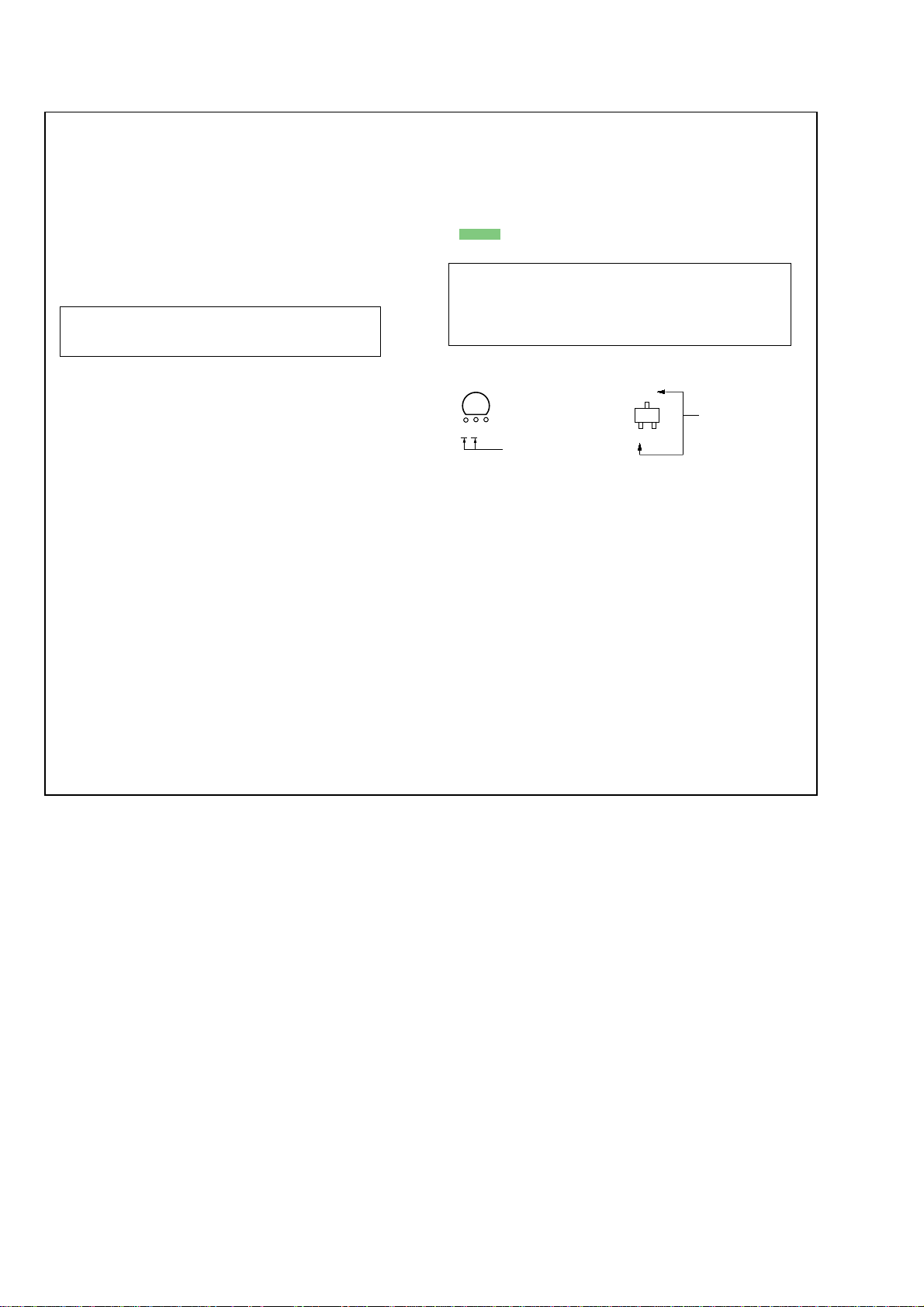
• Indication of transistor.
: Pattern from the side which enables seeing.
Caution:
Pattern face side: Parts on the pattern face side seen from
(SIDE B) the pattern face are indicated.
Parts face side: Parts on the parts face side seen from
(SIDE A) the parts face are indicated.
C
Q
CEB
These are omitted
E
These are omitte
30
 Loading...