

Sony HCDDZ-560, HCDDZ-370, HCDDZ-570, HCDDZ-660, HCDDZ-777 Service manual
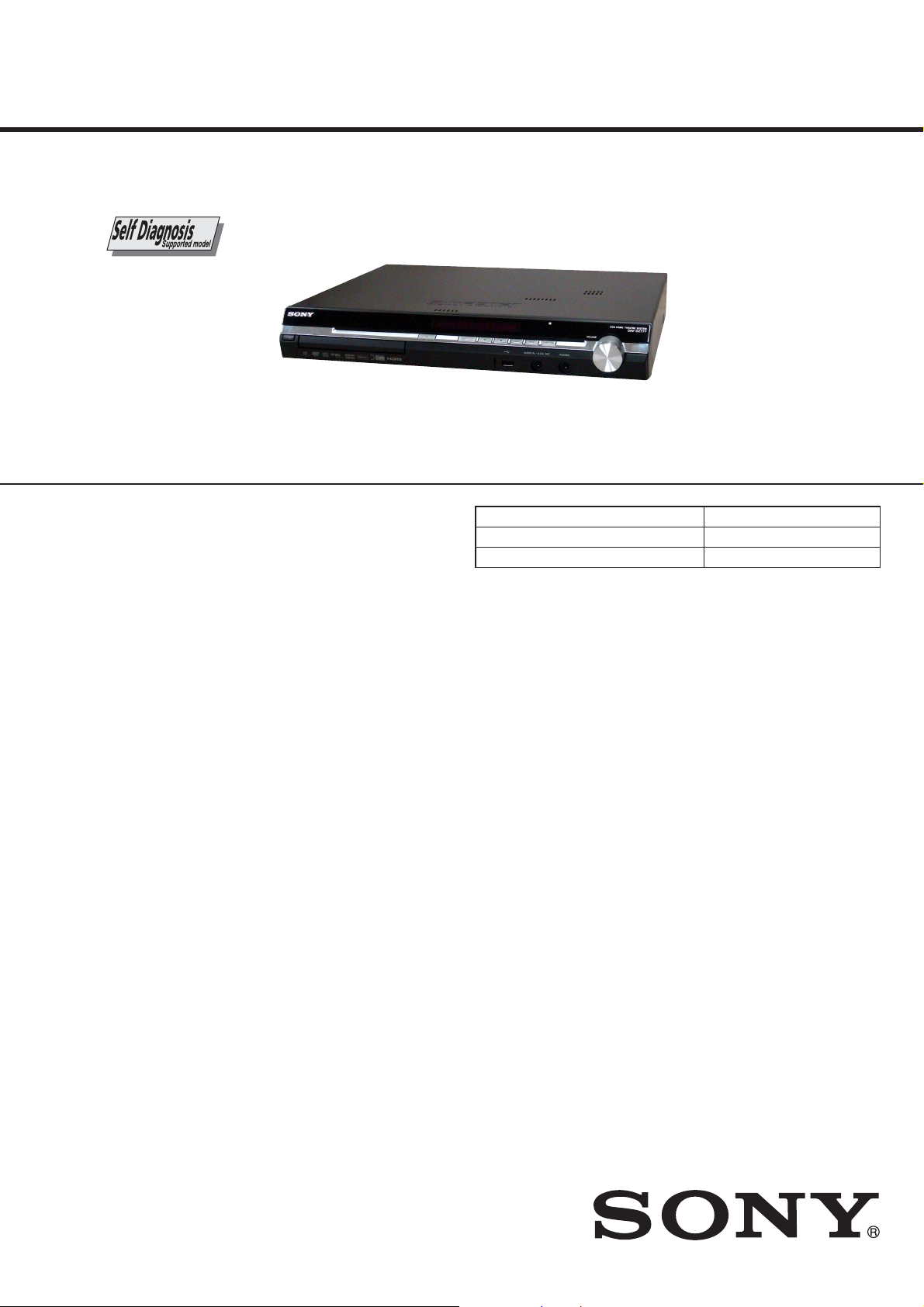
HCD-DZ370/DZ560/DZ570/
DZ660/DZ777
SERVICE MANUAL
Ver. 1.1 2008.05
Photo : HCD-DZ777
• HCD-DZ370/DZ560/DZ570/DZ660/DZ777 are the amplifi er, DVD/CD
and tuner section in DAV-DZ370/DZ560/DZ570/DZ660/DZ777.
This system incorporates with Dolby* Digital and Dolby Pro
Logic (II) adaptive matrix surround decoder and the DTS** Digital
Surround System.
* Manufactured under license from Dolby Laboratories.
“Dolby”, “Pro Logic”, and the double-D symbol are trademarks
of Dolby Laboratories.
** Manufactured under license from DTS, Inc.
“DTS” and “DTS Digital Surround” are registered trademarks
of DTS, Inc.
SPECIFICATIONS
Model Name Using Similar Mechanism HCD-DZ260/DZ270/HDZ278
Mechanism Type CDM85-DVBU102
Optical Pick-up Name KHM-313CAA
AEP Model
UK Model
HCD-DZ560/DZ660
E Model
HCD-DZ370/DZ570/DZ777
Australian Model
HCD-DZ570/DZ777
PX Model
HCD-DZ570
Amplifi er Section (DZ370)
Stereo mode (rated) 108 W + 108 W (at 3 ohms,
1 kHz, 1% THD)
Surround mode (reference) RMS output power
FL/FR/C/SL/SR*: 143
watts (per channel at 3
ohms, 1 kHz, 10% THD)
Subwoofer*: 285 watts (at
1.5 ohms, 80 Hz, 10% THD)
Amplifi er Section (DZ570)
Stereo mode (rated) 108 W + 108 W (at 3 ohms,
1 kHz, 1% THD)
Surround mode (reference) RMS output power
FL/FR/C/SL/SR*: 142
watts (per channel at 3
ohms, 1 kHz, 10% THD)
Subwoofer*: 140 watts (at
3 ohms, 80 Hz, 10% THD)
Amplifi er Section (DZ560/DZ660)
Stereo mode (rated) 108 W + 108 W (at 3 ohms,
1 kHz, 1% THD)
Surround mode (reference) RMS output power
FL/FR/C/SL/SR*: 142
watts (per channel at 3
ohms, 1 kHz, 10% THD)
Subwoofer*: 140 watts (at
3 ohms, 80 Hz, 10% THD)
Amplifi er Section (DZ777)
Stereo mode (rated) 108 W + 108 W (at 3 ohms,
1 kHz, 1% THD)
Surround mode (reference) RMS output power
FL/FR/C/SL/SR*: 143
watts (per channel at 3
ohms, 1 kHz, 10% THD)
Subwoofer*: 285 watts (at
1.5 ohms, 80 Hz, 10%
THD)
* Depending on the decoding mode settings and the
source, there may be no sound output.
Inputs (Analog) (DZ370/DZ570)
TV/VIDEO (AUDIO IN) Sensitivity: 450/250 mV
AUDIO IN Sensitivity: 250/125 mV
Inputs (Analog) (DZ560)
TV (AUDIO IN) Sensitivity: 450/250 mV
AUDIO IN Sensitivity: 250/125 mV
Inputs (Analog) (DZ660)
TV (AUDIO IN) Sensitivity: 450/250 mV
LINE (AUDIO IN) Sensitivity: 450/250 mV
AUDIO IN Sensitivity: 250/125 mV
Inputs (Analog) (DZ777)
TV (AUDIO IN) Sensitivity: 450/250 mV
SAT/CABLE (AUDIO IN) Sensitivity: 450/250 mV
AUDIO IN Sensitivity: 250/125 mV
Inputs (Digital) (DZ370/DZ570)
TV/VIDEO (COAXIAL IN/OPTICAL IN)
Impedance: 75 ohms/Inputs (Digital) (DZ560/DZ660/DZ777)
TV (COAXIAL IN/OPTICAL IN)
Impedance: 75 ohms/Outputs (Analog)
Phones Accepts low- and high impedance headphones.
Super Audio CD/DVD System
Laser Semiconductor laser
(Super Audio CD/DVD: λ
= 650 nm)
(CD: λ = 790 nm)
Emission duration:
continuous
Signal format system
Mexican and Latin American models:
NTSC
Other models: NTSC/PAL
USB Section
Supported bit rate
MP3 (MPEG 1 Audio Layer-3):
32 kbps - 320 kbps
WMA: 48 kbps - 192 kbps
AAC: 48 kbps - 320 kbps
– Continued on next page –
9-889-024-02
2008E04-1
2008.05
©
DVD RECEIVER
Sony Corporation
Audio Business Group
Published by Sony Techno Create Corporation
HCD-DZ370/DZ560/DZ570/DZ660/DZ777
Ver. 1.1
Sampling frequencies
MP3 (MPEG 1 Audio Layer-3):
32/44.1/48 kHz
WMA: 44.1 kHz
AAC: 44.1 kHz
(USB) port:
Maximum current: 500 mA
Tuner Section
System PLL quartz-locked digital
synthesizer
FM tuner section
Tuning range
North American models: 87.5 MHz - 108.0 MHz
(100 kHz step)
Other models: 87.5 MHz - 108.0 MHz (50
kHz step)
Antenna (aerial) FM wire antenna (aerial)
Antenna (aerial) terminals 75 ohms, unbalanced
Intermediate frequency 10.7 MHz
AM tuner section
Tuning range
North American, Mexican, and Latin American
models:
530 kHz - 1,710 kHz (with
the interval set at 10 kHz)
531 kHz - 1,710 kHz (with
the interval set at 9 kHz)
European, Russian, and Middle Eastern models:
531 kHz - 1,602 kHz (with
the interval set at 9 kHz)
Australian and New Zealand models:
531 kHz - 1,710 kHz (with
the interval set at 9 kHz)
530 kHz - 1,710 kHz (with
the interval set at 10 kHz)
Other models: 531 kHz - 1,602 kHz (with
the interval set at 9 kHz)
530 kHz - 1,610 kHz (with
the interval set at 10 kHz)
Antenna (aerial) AM loop antenna (aerial)
Intermediate frequency 450 kHz
Video Section (DZ370/DZ570/DZ777)
Outputs VIDEO: 1 Vp-p 75 ohms
COMPONENT:
Y: 1 Vp-p 75 ohms
P
75 ohms
HDMI OUT: Type A (19
pin)
B/CB, PR/CR: 0.7 Vp-p
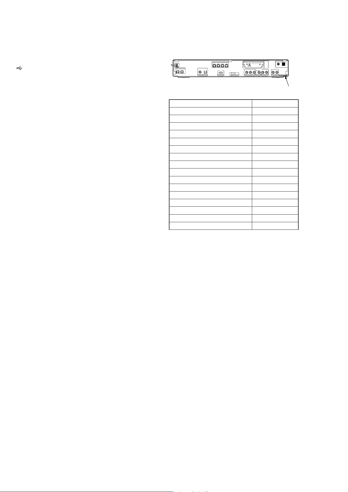
MODEL IDENTIFICATION
– Back Panel –
Model Part No.
DZ370: E12 model
DZ560: UK model
DZ660: AEP, UK model
DZ777: E3 model
DZ777: AUS model
DZ777: KR model
DZ777: E15 model
DZ570: E12 model
DZ570: E3 model
DZ570: MX model
DZ570: AUS model
DZ570: KR model
DZ570: E32 model
DZ570: TW model
DZ570: E15 model
DZ570: PX model
• Abbreviation
AUS : Australian model
E3 : 240 V AC Area in E model
E12 : 220-240 V AC area in E model
E15 : Iran model
E32 : 110 – 240V AC area in E model
KR : Korean model
MX : Mexican model
TW : Taiwan model
Parts No.
3-273-759-9[]
3-273-761-0[]
3-273-761-1[]
3-273-761-3[]
3-273-761-4[]
3-273-761-6[]
3-273-761-9[]
3-273-762-0[]
3-273-762-1[]
3-273-762-2[]
3-273-762-3[]
3-273-762-6[]
3-273-762-7[]
3-273-762-8[]
3-273-762-9[]
3-875-160-1[]
Video Section (DZ560/DZ660)
Outputs VIDEO: 1 Vp-p 75 ohms
R/G/B: 0.7 Vp-p 75 ohms
HDMI OUT: Type A (19
pin)
General
Power requirements
Mexican models: 120 V AC, 60 Hz
Taiwan models: 120 V AC, 50/60 Hz
Latin American models: 110 V - 240 V AC, 50/60 Hz
Other models: 220 V - 240 V AC, 50/60 Hz
Power consumption On: 170 W
Standby: 0.3 W (at the
Power Saving mode)
Output voltage (DIGITAL MEDIA PORT)
DC 5 V
Output current (DIGITAL MEDIA PORT)
700 mA
imensions (approx.) 430 mm × 66 mm × 385 mm
(w/h/d) incl. projecting parts
Mass (approx.) 4.2 kg
Design and specifi cations are subject to change
without notice.
Special Component Notice
The components identifi ed by mark 9 contain confi dential infor-
mation.
Strictly follow the instructions whenever the components are repaired and/or replaced.
SAFETY-RELATED COMPONET WARNING!
COMPONENTS IDENTIFIED BY MARK 0 OR DOTTED LINE
WITH MARK 0 ON THE SCHEMATIC DIAGRAMS AND IN
THE PARTS LIST ARE CRITICAL TO SAFE OPERATION.
REPLACE THESE COMPONENTS WITH SONY PARTS
WHOSE PART NUMBERS APPEAR AS SHOWN IN THIS
MANUAL OR IN SUPPLEMENTS PUBLISHED BY SONY.
2
HCD-DZ370/DZ560/DZ570/DZ660/DZ777
Laser component in this product is capable of emitting radiation exceeding the limit for Class 1.
This appliance is classifi ed as a
CLASS 1 LASER product.
This marking is located on the
rear or bottom exterior.
CAUTION
Use of controls or adjustments or performance of procedures other than
those specifi ed herein may result in hazardous radiation exposure.
Notes on chip component replacement
• Never reuse a disconnected chip component.
• Notice that the minus side of a tantalum capacitor may be dam-
aged by heat.
Flexible Circuit Board Repairing
• Keep the temperature of soldering iron around 270 °C during
repairing.
• Do not touch the soldering iron on the same conductor of the
circuit board (within 3 times).
• Be careful not to apply force on the conductor when soldering
or unsoldering.
About This Operating
Instructions
• The instructions in this Operating Instructions
describe the controls on the remote. You can
also use the controls on the unit if they have the
same or similar names as those on the remote.
• The Control Menu items may vary depending
on the area.
• “DVD” may be used as a general term for a
DVD VIDEO, DVD+RW/DVD+R, and DVDRW/DVD-R.
• Measurements are expressed in feet (ft) for
North American models.
• The default setting is underlined.
About the S-AIR function
The system is compatible with the S-AIR
function, which allows transmission of sound
between S-AIR products wirelessly.
The following S-AIR products can be used with
the system:
UNLEADED SOLDER
Boards requiring use of unleaded solder are printed with the leadfree mark (LF) indicating the solder contains no lead.
(Caution: Some printed circuit boards may not come printed with
the lead free mark due to their particular size)
: LEAD FREE MARK
Unleaded solder has the following characteristics.
• Unleaded solder melts at a temperature about 40 °C higher
than ordinary solder.
Ordinary soldering irons can be used but the iron tip has to be
applied to the solder joint for a slightly longer time.
Soldering irons using a temperature regulator should be set to
about 350 °C.
Caution: The printed pattern (copper foil) may peel away if the
heated tip is applied for too long, so be careful!
• Strong viscosity
Unleaded solder is more viscous (sticky, less prone to fl ow)
than ordinary solder so use caution not to let solder bridges
occur such as on IC pins, etc.
• Usable with ordinary solder
It is best to use only unleaded solder but unleaded solder may
also be added to ordinary solder.
• Surround amplifier: You can enjoy surround
speaker sound wirelessly.
• S-AIR receiver: You can enjoy system sound
in another room.
These S-AIR products can be purchased as an
option (the S-AIR product lineup differs
depending on the area).
Notes or instructions for the surround amplifier
or S-AIR receiver in this operating instructions
refer only to when the surround amplifier or
S-AIR receiver is used.
For details on the S-AIR function, see “Using an
S-AIR Product”.
3
HCD-DZ370/DZ560/DZ570/DZ660/DZ777
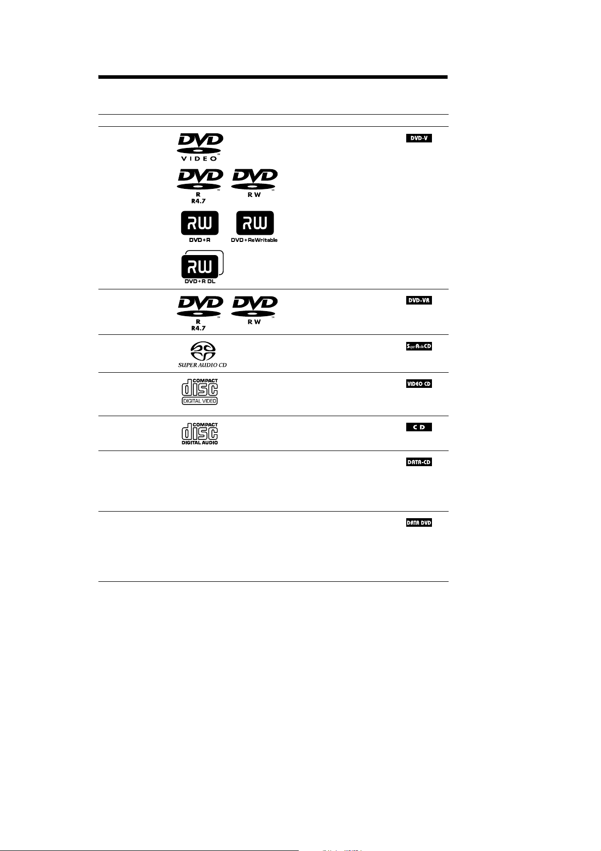
Playable Discs
nocIscitsiretcarahCogolcsiDepyT
OEDIVDVD•OEDIVDVD
• DVD-R/DVD-RW in DVD
VIDEO format or video mode
• DVD+R/DVD+RW in DVD
VIDEO format
VR (Video
Recording) mode
• DVD-R/DVD-RW in VR (Video
Recording) mode (except for
DVD-R DL)
DCoiduArepuS•DCoiduArepuS
•Super VCD
• CD-R/CD-RW/CD-ROM in video
CD format or Super VCD format
DCoiduA•DC
• CD-R/CD-RW in audio CD format
,and
,and
niMOR-DC/WR-DC/R-DC•–DCATAD
5)
Level 1/
/WR-DVD/R-DVD/MOR-DVD•–DVDATAD
DATA
C
D format,containing MP3
1)
files
,JPEGimagefiles2),and
DivX video files
conforming to ISO 9660
Level 2, or Joliet (extended format)
DVD+R/DVD+RW in DATA
DVD format, containing MP3
1)
files
,JPEGimagefiles2),and
DivX video files
conforming to UDF (Universal
Disk Format)
3)4)
3)4)
)scsid0.2dna1.1.reV(DCOEDIV•DCOEDIV
1)
MP3 (MPEG1 Audio Layer 3) is a standard format defined by ISO/MPEG which compresses audio data. MP3 files
must be in MPEG1 Audio Layer 3 format.
GB
5
4

HCD-DZ370/DZ560/DZ570/DZ660/DZ777
2)
JPEG image files must conform to the DCF image file format. (DCF “Design rule for Camera File system”: Image
standards for digital cameras regulated by Japan Electronics and Information Technology Industries Association
(JEITA).)
3)
DivX®is a video file compression technology, developed by DivX, Inc.
4)
DivX, DivX Certified, and associated logos are trademarks of DivX, Inc. and are used under license.
5)
A logical format of files and folders on CD-ROMs, defined by ISO (International Organization for
Standardization).
“DVD-RW,” “DVD+RW,” “DVD+R,”“DVD VIDEO,” and the “CD” logos are trademarks.
Example of discs that the system cannot play
The system cannot play the following discs:
• CD-ROM/CD-R/CD-RW other than those recorded in the formats listed on page 5
•CD-ROMrecordedinPHOTOCDformat
• Data part of CD-Extra
• CD Graphics disc
• DVD Audio
• DATA DVD that does not contain MP3 files, JPEG image files, or DivX video files
•DVD-RAM
Also, the system cannot play the following discs:
• A DVD VIDEO with a different region code
• A disc that has a non-standard shape (e.g., card, heart)
• A disc with paper or stickers on it
• A disc that has the adhesive of cellophane tape or a sticker still left on it
Note about CD-R/CD-RW/DVD-R/DVD-RW/DVD+R/DVD+RW
In some cases,CD-R/CD-RW/DVD-R/DVD-RW/DVD+R/DVD+RW cannot beplayed on thissystem
due to the recording quality or physical condition of the disc, or the characteristics of the recording
device and authoring software.
The disc will not play if it has not been correctly finalized. For more information, refer to the operating
instructions for the recording device.
Note that some playback functions may not work with some DVD+RWs/DVD+Rs, even if they have
been correctly finalized. In this case, view the disc by normal playback. Also some DATA CDs/DATA
DVDs created in Packet Write format cannot be played.
Music discs encoded with copyright protection technologies
This product is designed to play back discs that conform to the Compact Disc (CD) standard.
Recently, various music discs encoded with copyright protection technologies are marketed by some
record companies. Please be aware that among those discs, there are some that do not conform to the
CD standard and may not be playable by this product.
Note on DualDiscs
A DualDisc is a two sided disc product which mates DVD recorded material on one side with digital
audio material on the other side. However, since the audio material side does not conform to the
Compact Disc (CD) standard, playback on this product is not guaranteed.
GB
6
5
HCD-DZ370/DZ560/DZ570/DZ660/DZ777
About Multi Session CD
• This system can play a Multi Session CD when an MP3 file is contained in the first session. Any
subsequent MP3 files recorded in later sessions can also be played back.
• This system can play a Multi Session CD when a JPEG image file is contained in the first session.
Any subsequent JPEG image files recorded in later sessions can also be played back.
• If MP3 files and JPEG image files in music CD format or video CD format are recorded in the first
session, only the first session will be played back.
Region code
Your system has a region code printed on the rear of the unit and will only play a DVD labeled with
the same region code.
A DVD VIDEO labeled will also play on this system.
If you try to play any other DVD VIDEO, the message [Playback prohibited by area limitations.] will
appear on the TVscreen.Depending on theDVD VIDEO, no region code indication may be given even
though playing the DVD VIDEO is prohibited by area restrictions.
Note about playback operations of a DVD or VIDEO CD
ALL
Some playback operations on a DVD or VIDEO CD may be intentionally set by software producers.
Since this system will play a DVD or VIDEO CD according to the disc contents the software producers
designed, some playback features may not be available. Be sure to read the operating instructions
supplied with the DVD or VIDEO CD.
Copyrights
This product incorporates copyright protection technology that is protected by U.S. patents and other
intellectual property rights. Use of this copyright protection technology must be authorized by
Macrovision, and isintended for home and other limited viewing uses only unless otherwise authorized
by Macrovision. Reverse engineering or disassembly is prohibited.
This system incorporates with Dolby* Digital and Dolby Pro Logic (II) adaptive matrix surround
decoder and the DTS** Digital Surround System.
* Manufactured under license from Dolby Laboratories.
“Dolby”, “Pro Logic”, and the double-D symbol are trademarks of Dolby Laboratories.
** Manufactured under license from DTS, Inc.
“DTS” and “DTS Digital Surround” are registered trademarks of DTS, Inc.
This system incorporates High-Definition Multimedia Interface (HDMITM) technology.
HDMI, the HDMI logo and High-Definition Multimedia Interface are trademarks or registered
trademarks of HDMI Licensing LLC.
“BRAVIA” and are trademarks of Sony Corporation.
“S-AIR” and its logo are trademarks of Sony Corporation.
GB
7
6
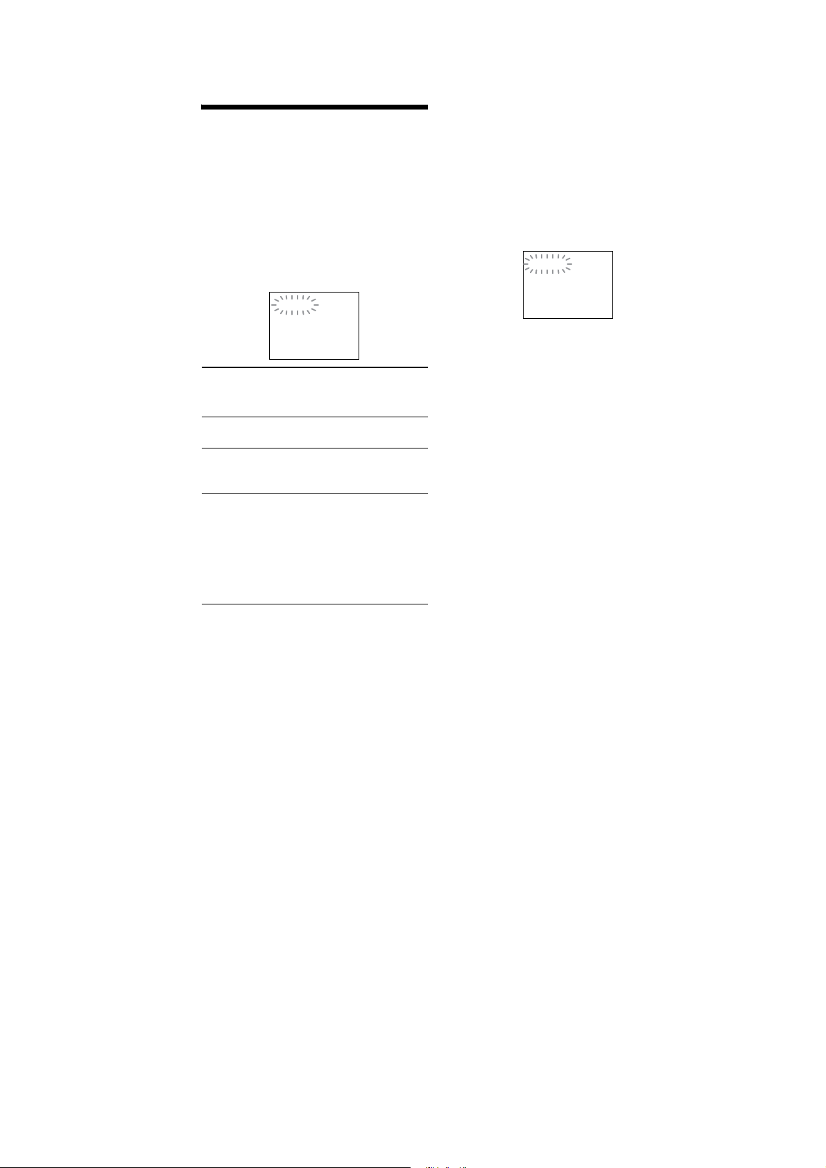
Self-diagnosis Function
(When letters/numbers appear in the
display)
When the self-diagnosis function is activated to
prevent the system from malfunctioning, a 5character service number (e.g., C 13 50) with a
combination of a letter and 4 digits appears on
the TV screen or front panel display. In this case,
checkthefollowingtable.
C:13:50
HCD-DZ370/DZ560/DZ570/DZ660/DZ777
When displaying the version
number on the TV screen
When you turn on the system, the version
number [VER.X.XX] (X is a number) may
appear on the TV screen. Although this is not a
malfunction and for Sony service use only,
normal system operation will not be possible.
Turn off the system, and then turn on the system
again to operate.
VER.X.XX
First 3
characters of
the service
number
C 13 The disc is dirty.
C 31 The disc is not inserted correctly.
EXX
(XX is a
number)
Cause and/or corrective action
Clean the disc with a soft cloth.
Restart the system, then re-insert
the disc correctly.
To prevent a malfunction, the
system has performed the selfdiagnosis function.
Contact your nearest Sony
dealer or local authorized Sony
service facility and give the 5character service number.
Example: E 61 10
100
GB
7

HCD-DZ370/DZ560/DZ570/DZ660/DZ777
TABLE OF CONTENTS
1. SERVICING NOTES ............................................. 9
2. GENERAL .................................................................. 11
3. DISASSEMBLY
3-1. Case ................................................................................ 24
3-2. POWER Board ................................................................ 24
3-3. Front Panel Section ........................................................ 25
3-4. Back Panel Section ......................................................... 25
3-5. DVD Mechanism Deck ................................................... 26
3-6. MAIN Board ................................................................... 26
3-7. IO-SCART Board (DZ560/DZ660),
IO-COMPONENT Board (DZ370/DZ570/DZ777) ....... 27
3-8. Tray ................................................................................. 27
3-9. Belt .................................................................................. 28
3-10. MS-203 Board ................................................................. 28
3-11. Base Unit ......................................................................... 29
3-12. Optical Pick-up ............................................................... 29
4. TEST MODE ............................................................ 30
5. ELECTRICAL ADJUSTMENTS ........................ 35
6. DIAGRAMS
6-1. Block Diagram –RF Section– ......................................... 38
6-2. Block Diagram –VIDEO Section– ................................. 39
6-3. Block Diagram –AUDIO Section– ................................. 40
6-4. Block Diagram –AMP Section– ..................................... 41
6-5. Block Diagram –POWER Section– ................................ 42
6-6. Printed Wiring Board –MAIN Board (Side A)– ............. 43
6-7. Printed Wiring Board –MAIN Board (Side B)– ............. 44
6-8. Schematic Diagram –MAIN Board (1/9)– ...................... 45
6-9. Schematic Diagram –MAIN Board (2/9)– ...................... 46
6-10. Schematic Diagram –MAIN Board (3/9)– ...................... 47
6-11. Schematic Diagram –MAIN Board (4/9),
MS-203 Board– ............................................................... 48
6-12. Schematic Diagram –MAIN Board (5/9)– ...................... 49
6-13. Schematic Diagram –MAIN Board (6/9)– ...................... 50
6-14. Schematic Diagram –MAIN Board (7/9)– ...................... 51
6-15. Schematic Diagram –MAIN Board (8/9)– ...................... 52
6-16. Schematic Diagram –MAIN Board (9/9)– ...................... 53
6-17. Printed Wiring Board –IO-SCART Board
(DZ560/DZ660)– ............................................................ 54
6-18. Schematic Diagram –IO-SCART Board
(DZ560/DZ660)– ............................................................ 55
6-19. Printed Wiring Board –IO-COMPONENT Board
(DZ370/DZ570/DZ777)– ................................................ 56
6-20. Schematic Diagram –IO-COMPONENT Board
(DZ370/DZ570/DZ777)– ................................................ 57
6-21. Printed Wiring Boards –JACK, P-SW Board– ............... 58
6-22. Schematic Diagram –JACK, P-SW Board– .................... 59
6-23. Printed Wiring Boards
–FL, MS-203, SPEAKER Board– .................................. 60
6-24. Schematic Diagram –FL, SPEAKER Board– ................. 61
6-25. Printed Wiring Board –S-AIR-CON Board– .................. 62
6-26. Schematic Diagram –S-AIR-CON Board– ..................... 63
6-27. Printed Wiring Board –POWER Board– ........................ 64
6-28. Schematic Diagram –POWER Board– ........................... 65
7. EXPLODED VIEWS
7-1. Overall Section ............................................................... 78
7-2. Front Panel Section ......................................................... 79
7-3. Chassis Section ............................................................... 80
7-4. DVD Mechanism Deck Section (CDM85-DVBU102) .. 81
8. ELECTRICAL PARTS LIST .............................. 82
8
HCD-DZ370/DZ560/DZ570/DZ660/DZ777
SECTION 1
SERVICING NOTES
NOTES ON HANDLING THE OPTICAL PICK-UP
BLOCK OR BASE UNIT
The laser diode in the optical pick-up block may suffer electrostatic break-down because of the potential difference generated by the
charged electrostatic load, etc. on clothing and the human body.
During repair, pay attention to electrostatic break-down and also
use the procedure in the printed matter which is included in the
repair parts.
The fl exible board is easily damaged and should be handled with
care.
NOTES ON LASER DIODE EMISSION CHECK
The laser beam on this model is concentrated so as to be focused
on the disc refl ective surface by the objective lens in the optical
pickup block. Therefore, when checking the laser diode emission,
observe from more than 30 cm away from the objective lens.
LASER DIODE AND FOCUS SEARCH
1. Open the case and turn POWER on with no disc inserted.
2. Confi rm that the following operation is performed while
observing the objecting lens from the clearance of DVD
mechanism deck.
1) Confi rm that laser beam is spread.
2) Up and down motion of the objective lens. (2 times)
DISC TRAY LOCK
The disc tray lock function for the antitheft of an demonstration
disc in the store is equipped.
Setting Procedure :
1. Press the [
2. Press the [FUNCTION] button to set DVD function.
3. Insert a disc.
4. Press the [x] button and the [A] button simultaneously for fi ve
seconds.
5. The message “LOCKED” is displayed and the tray is locked.
Releasing Procedure :
1. Press the [x] button and the [A] button simultaneously for fi ve
seconds again.
2. The message “UNLOCKED” is displayed and the tray is
unlocked.
Note: When “LOCKED” is displayed, the tray lock is not released by
turning power on/off with the [?/1] button.
On cleaning discs, disc/lens cleaners
• Do not use cleaning discs or disc/lens cleaners (including wet or
spray types). These may cause the apparatus to malfunction.
IMPORTANT NOTICE
Caution: This system is capable of holding a still video image or
on-screen display image on your television screen indefi nitely.
If you leave the still video image or on-screen display image
displayed on your TV for an extended period of time you risk
permanent damage to your television screen.
Projection televisions are especially susceptible to this.
] button to turn the set on.
?/1
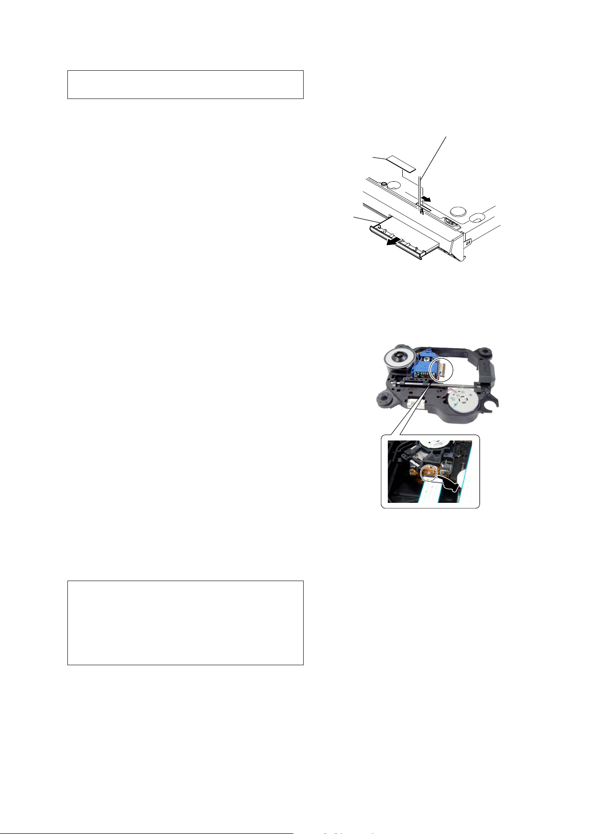
How to open the disc table when power switch turns off
Insert a tapering driver into the aperture of the unit bottom, and
slide it in the direction of the arrow.
Peel off the seal and so the lever is moved
in the direction of the arrow with the thin rod.
seal
tray
Precaution when installing a new OP unit/
Precaution before unsoldering the static electricity
prevention solder bridge
When installing a new OP unit, be sure to connect the fl exible
printed circuit board fi rst of all before removing the static electricity
prevention solder bridge by unsoldering.
Remove the static electricity prevention solder bridge by
unsoldering after the fl exible printed circuit board has already been
connected.
(Do not remove nor unsolder the solder bridge as long as the OP
unit is kept standalone.)
Attention when transported
Use this mode when returning the set to the customer after repair.
Procedure:
1. Press the [
2. Press the [FUNCTION] button to set the function “DVD”.
3. Remove all discs, and then press two buttons [H] and [
simultaneously.
4. After a message “MECHA LOCK” is displayed on the
fl uorescent indicator tube, pull out the AC plug.
5. To exit from this mode, press the [
on.
] button to turn the set on.
?/1
] button to turn the set
?/1
?/1
]
9
HCD-DZ370/DZ560/DZ570/DZ660/DZ777
Radiation Sheet
When peeling off the heat radiation sheet, try always to put it on
be former position.
POWER board
radiation sheet
10
HCD-DZ370/DZ560/DZ570/DZ660/DZ777
SECTION 2
GENERAL
This section is extracted
from instruction manual.
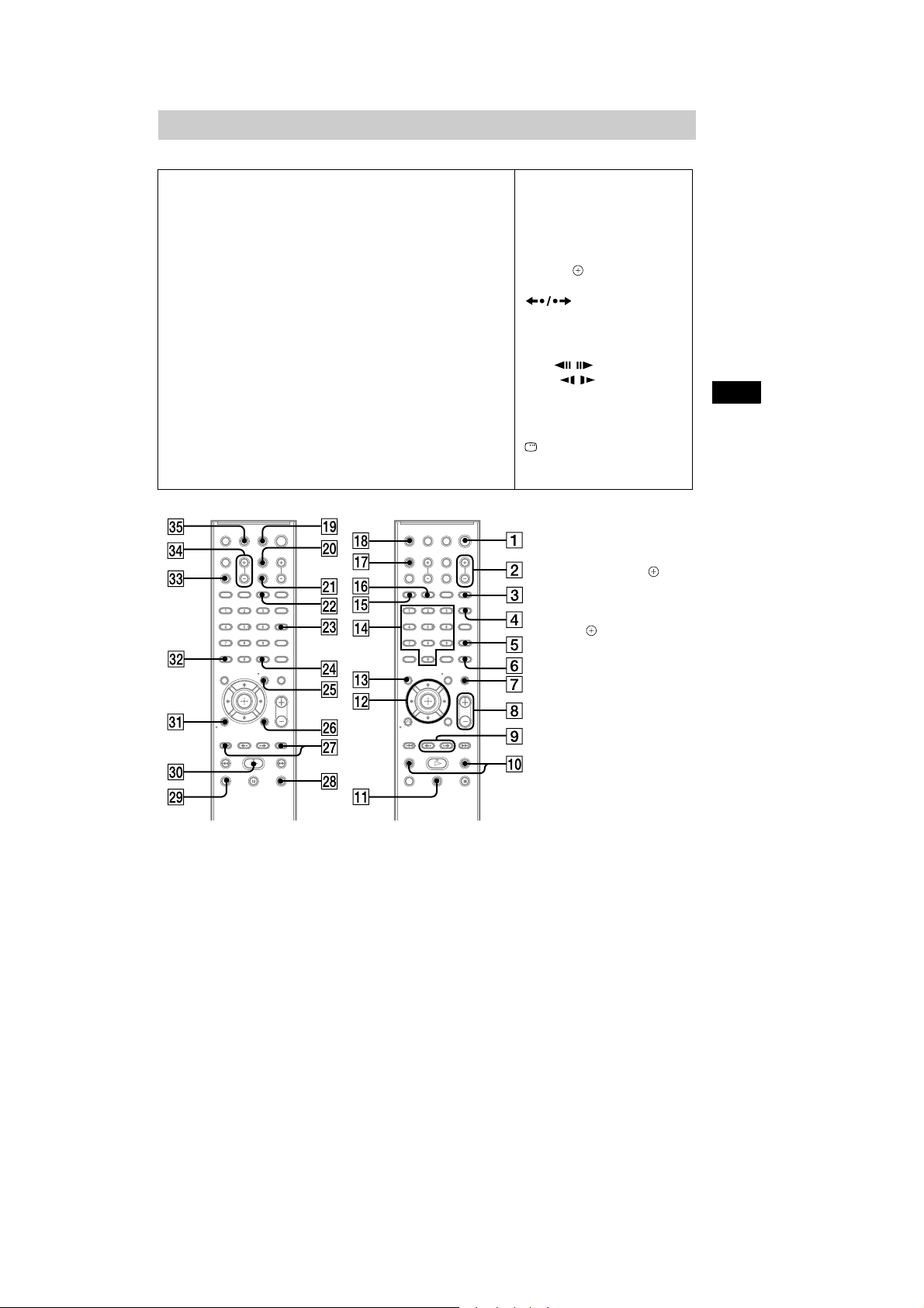
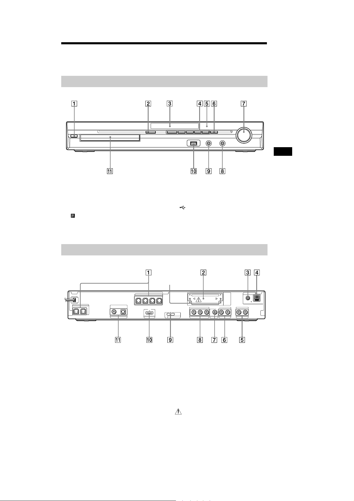
Index to Parts and Control
(DZ370/DZ570)
For more information, refer to the pages indicated in parentheses.
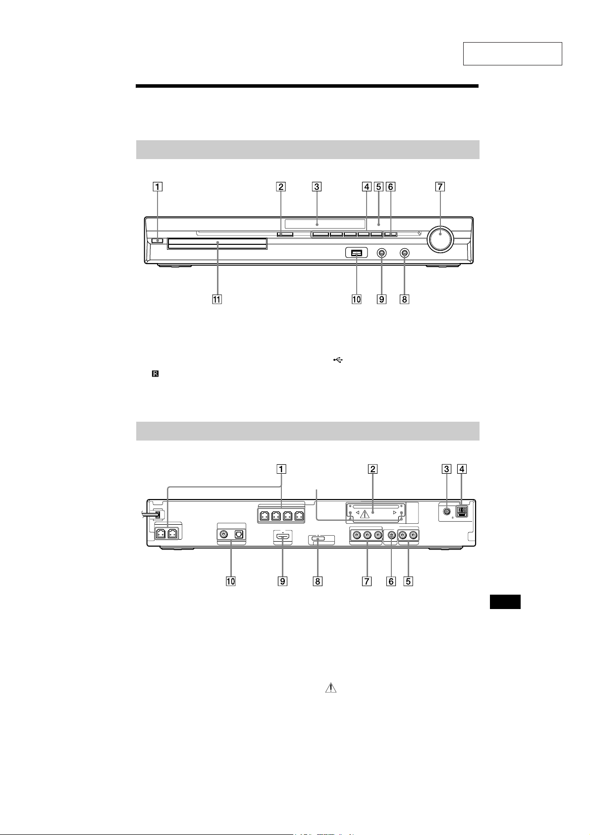
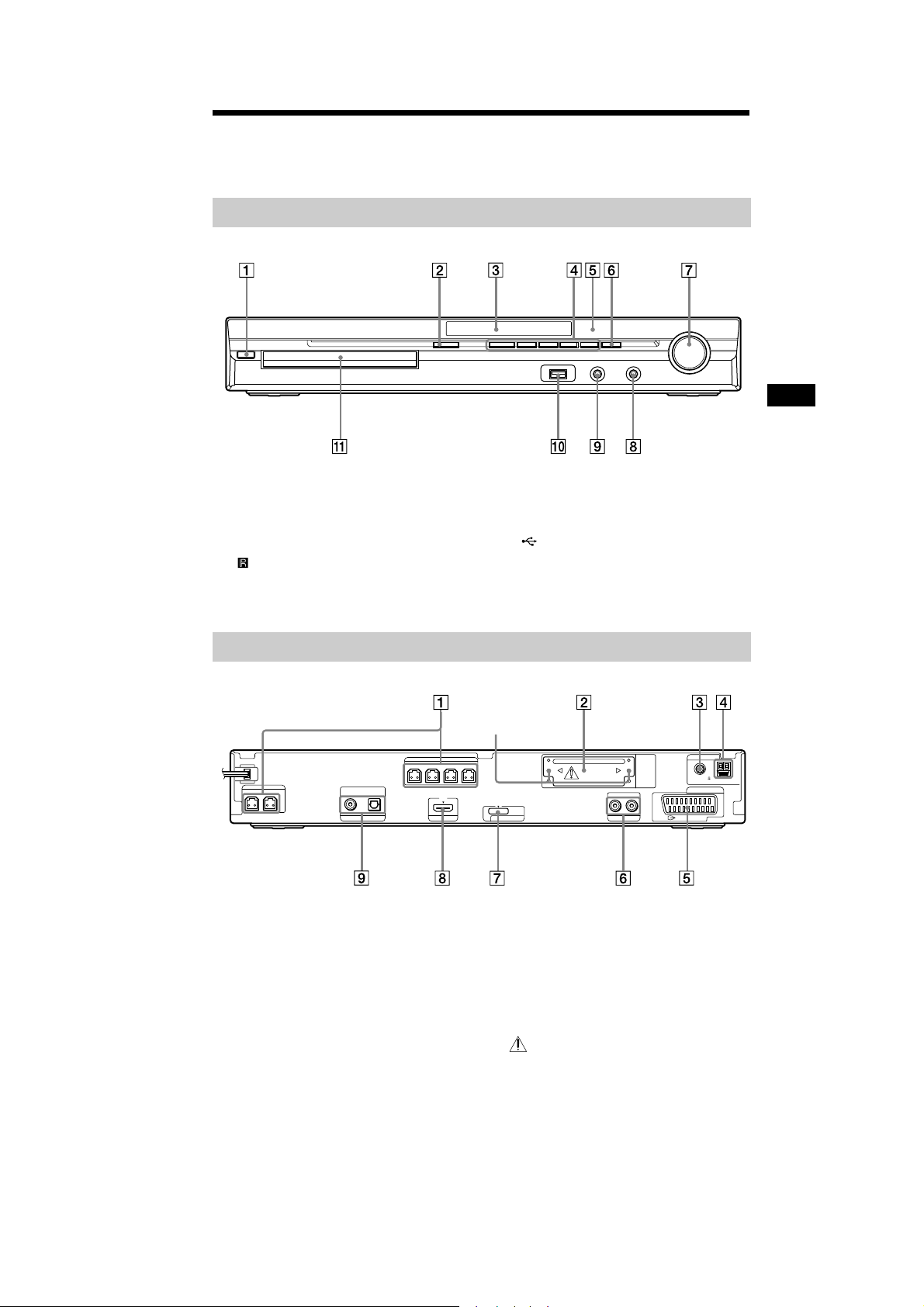
Front panel
" / (on/standby) (31, 94)
# " (open/close) (39)
$ Front panel display (114)
% Play operation buttons (39)
& (remote sensor) (10)
' FUNCTION (34)
( VOLUME control (39)
) PHONES jack (39)
* AUDIO IN/A.CAL MIC jack (27, 31, 88)
+ (USB)port(71)
, Disc tray (39)
Rear panel
SPEAKER
FRONTR FRONTL SUR R SUR L
SPEAKER
CENTER SUBWOOFER
" SPEAKER jacks (24)
# EZW-T100 slot (27)
$ COAXIAL 75Ω FM jack (29)
% AM terminal (29)
& TV/VIDEO (AUDIO IN R/L) jacks (25, 27)
' VIDEO OUT jack (25)
DIGITAL IN
COAXIAL OPTICAL
TUOIMDHOEDIV/VT
Screws*
EZW-T100
DC5V
DMPORT
0.7A MAX
B/CBPR/CR
Y
P
COMPONENTVIDEO OUT
AUDIO IN
VIDEO OUT TV/VIDEO
LR
( COMPONENT VIDEO OUT jacks (25)
) DMPORT (DIGITAL MEDIA PORT) jack
(27, 80)
* HDMI OUT jack (25)
+ TV/VIDEO (DIGITAL IN COAXIAL/
OPTICAL) jacks (25)
* CAUTION
Please do not remove the screws before
installing the EZW-T100.
ANTENNA
COAXIAL 75
FM
AM
Additional Information
11
HCD-DZ370/DZ560/DZ570/DZ660/DZ777
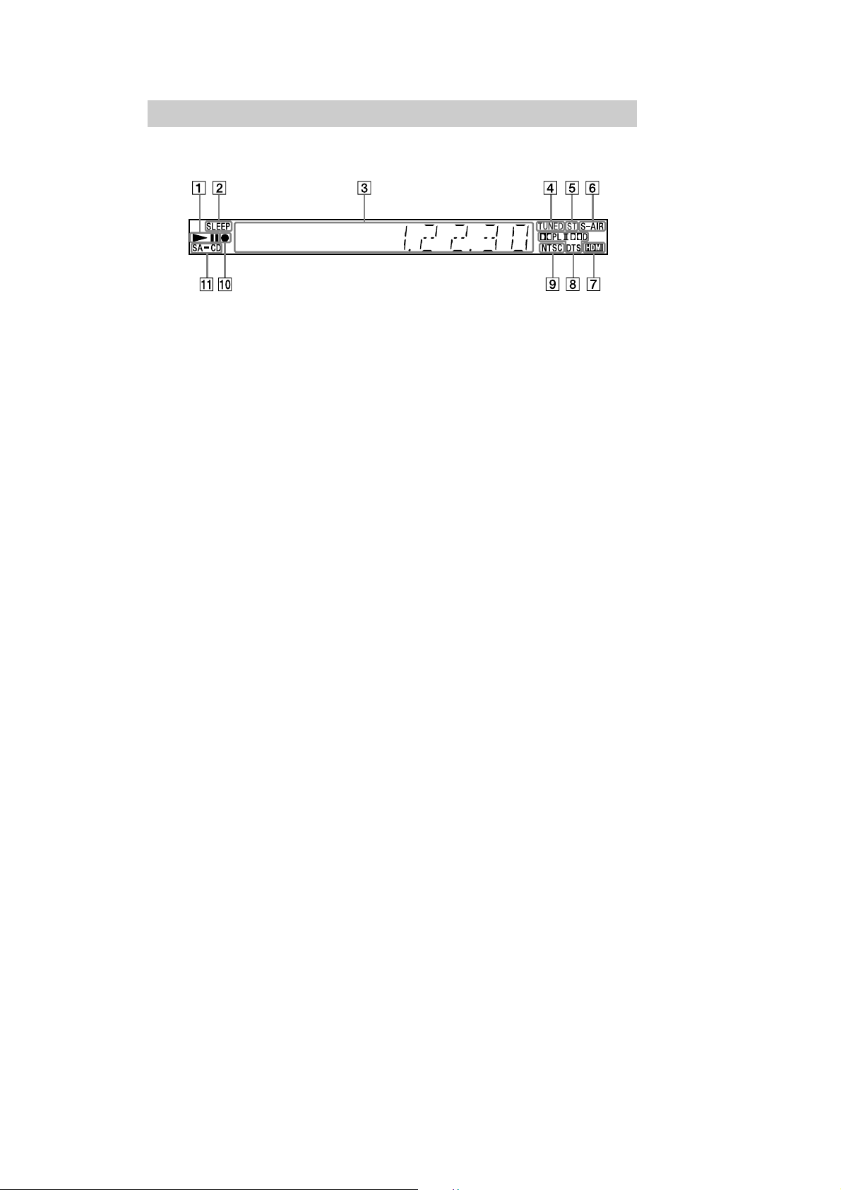
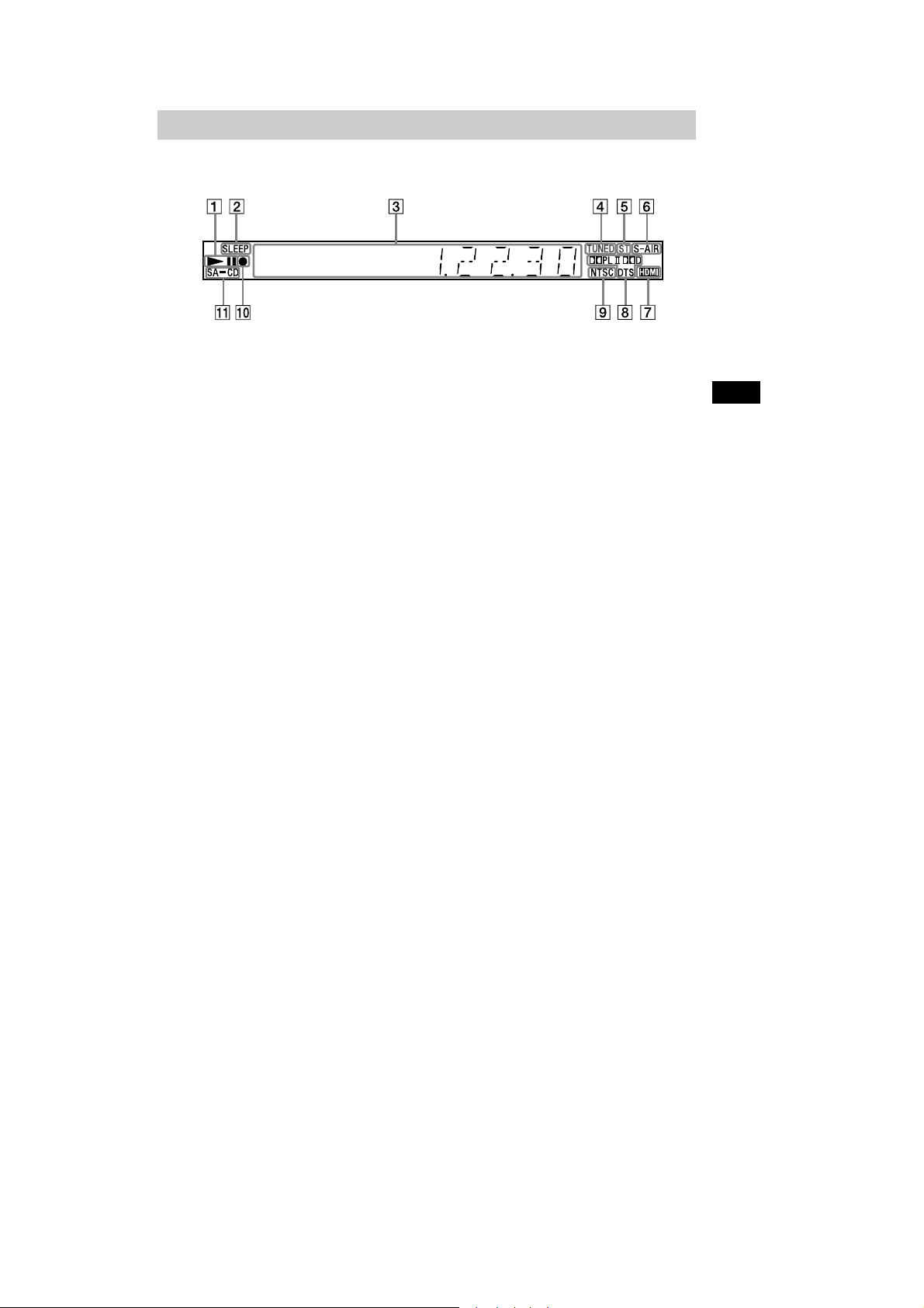
Front panel display
About the indications in the front panel display
" Playing status
# Flashes when the sleep timer is set.
(90)
$ Displays system’s status such as
chapter, title, or track number, time
information, radio frequency, playing
status, decoding mode, etc.
% Lights up when a station is received.
(Radio only) (65)
& Stereo/Monaural effect (Radio only)
(66)
' Lights up when the S-AIR transmitter
(not supplied) is inserted in the unit
and the system transmits the sound.
(81)
( Lights up when the HDMI OUT jack is
correctly connected to HDCP (Highbandwidth Digital Content Protection)
compliant device with HDMI or DVI
(Digital Visual Interface) input. (25)
) Current surround format (Except for
JPEG image file)
* Lights up when the color system is set
to NTSC. (Asian, Australian, and Middle
Eastern models only)
+ Lights up during USB recording/
copying. (77)
, Lights up when Super Audio CD/CD is
loaded. (42)
12
114
GB
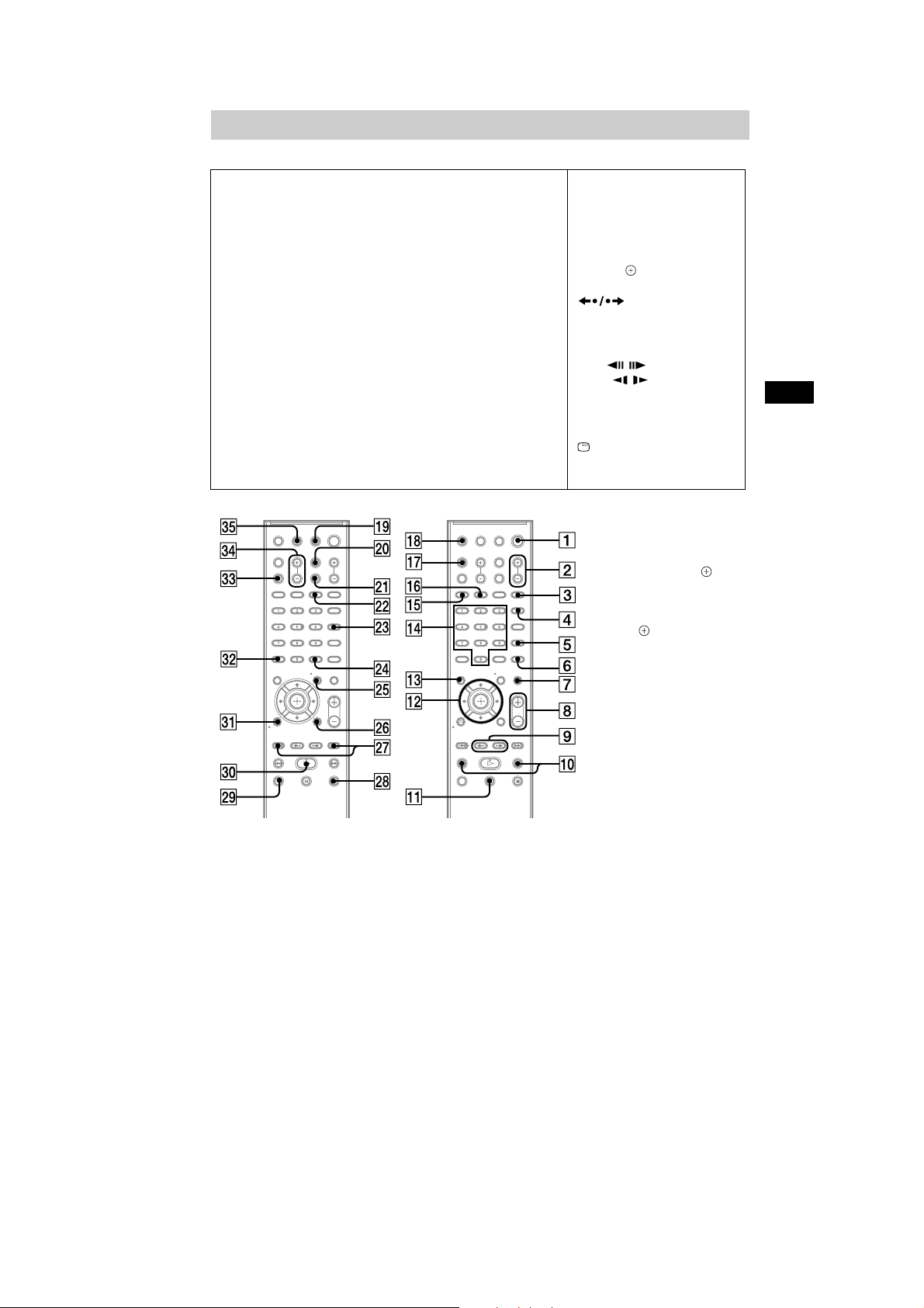
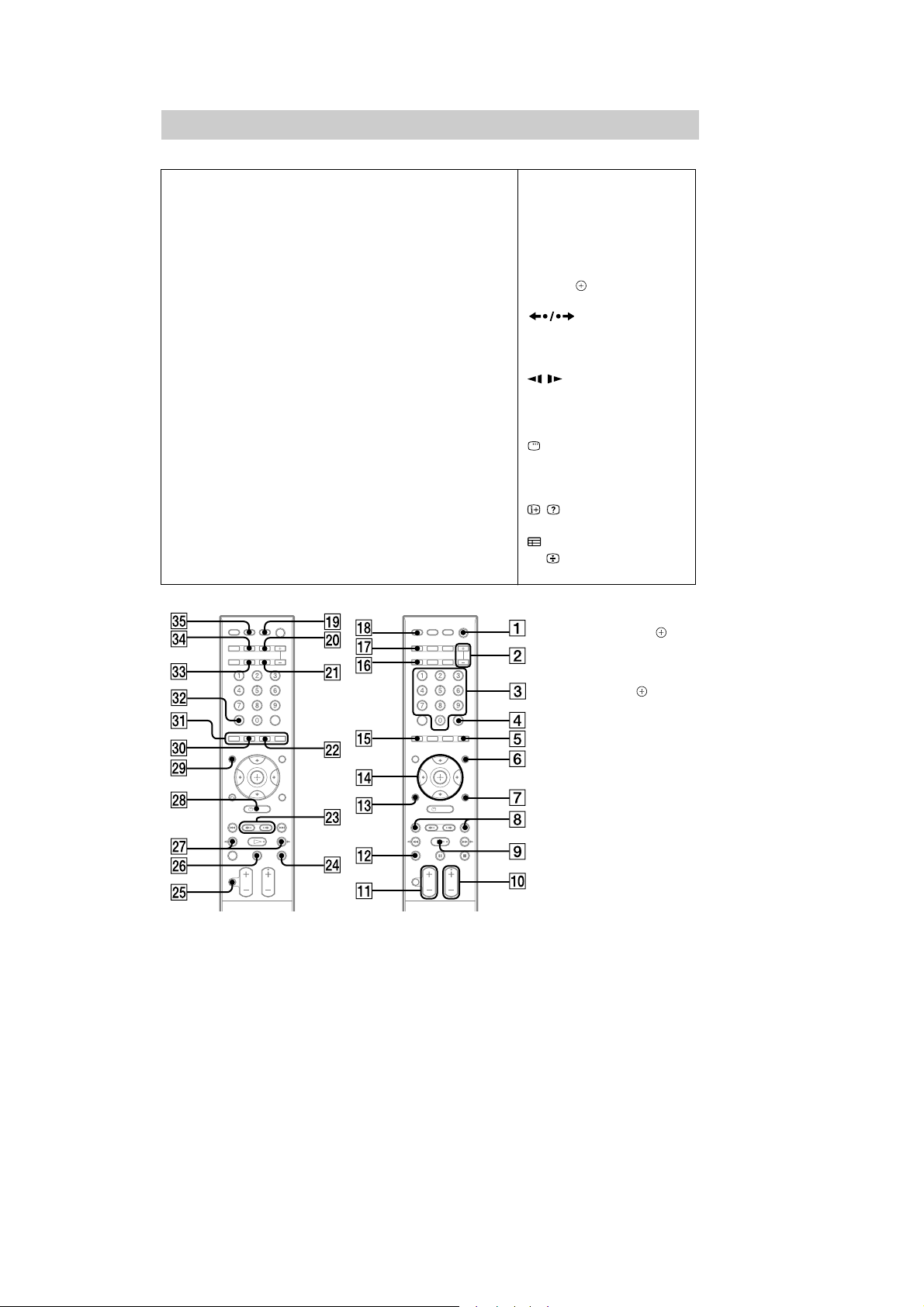
Remote control
ANGLE (40)
AUDIO RI (41)
CLEAR FT (44, 56, 66)
D.TUNING XT (66)
DISC SKIP
DISPLAY XB (67, 76, 91)
DVD MENU XH (47)
DVD TOP MENU RE (47)
DYNAMIC BASS (90)
ENTER
87)
FUNCTION +/– (34, 39)
MENU XH (89)
MUTING (39)
NIGHT XE (90)
ONE-TOUCH PLAY FH (69)
1)
FE
2)
XG (30, 31, 42, 44, 65,
HCD-DZ370/DZ560/DZ570/DZ660/DZ777
Z–PO–A
PICTURE NAVI RH (49, 73)
PRESET +/– XK (66)
PROG +/– XK (89)
S-AIR MODE
SLEEP RK (90)
SOUND MODE (38)
SUBTITLE XT (41)
SYSTEM MENU XG (30, 35, 90,
91)
THEATRE RL (68)
TOOLS XI (89)
TUNING +/– (65)
TV XM (89)
TV INPUT X (89)
TV VOL +/– FG (89)
VOLUME +/– (39)
SNOITPIRCSEDNOTTUBREDROLACITEBAHPLA
Number buttons RG (43, 65, 89)
</ (on/standby) (30, 31, 39)
TV </ (on/standby) RM (89)
$/9/Y/D/ RT (30, 31, 42, 44,
65, 87)
(39)
/ XK (39)
N/. (39
ST
SLOW / (39)
)(play) F (39)
Y (stop) XL (39)
9 (pause) RB (39)
0 RETURN FB (43, 89)
-/-- FT (89)
REPLAY/ADVANCE
)
EP / (39)
DISPLAY
3)
XI (31, 42, 44, 87)
Additional Information
1)
This button is not available
for this model.
2)
The ENTER button has the
same function as the
button. When you operate
the TV, the ENTER button is
used for selecting a channel,
andthe buttonisusedfor
selecting menu items
(page 89).
3)
This button is available for
the “DVD,” “USB,” or
“DMPORT” function.
Depending on the DIGITAL
MEDIA PORT adapter, this
button may not work.
115
GB
13
HCD-DZ370/DZ560/DZ570/DZ660/DZ777
Index to Parts and Control
(DZ560)
For more information, refer to the pages indicated in parentheses.
Front panel
" / (on/standby) (25, 88)
# " (open/close) (33)
$ Front panel display (108)
% Play operation buttons (33)
& (remote sensor) (9)
' FUNCTION (28)
( VOLUME control (33)
) PHONES jack (33)
* AUDIO IN/A.CAL MIC jack (21, 25, 82)
+ (USB)port(65)
, Disc tray (33)
Rear panel
SPEAKER
FRONTR FRONTL SUR R SUR L
SPEAKER
CENTER SUBWOOFER
" SPEAKER jacks (19)
# EZW-T100 slot (21)
$ COAXIAL 75Ω FM jack (23)
% AM terminal (23)
& EURO AV 5 OUTPUT (TO TV) jack (20)
DIGITAL IN
COAXIAL OPTICAL
TUOIMDHVT
Screws*
EZW-T100
DC5V
0.7A MAX
DMPORT
' DMPORT (DIGITAL MEDIA PORT) jack
(21, 74)
( HDMI OUT jack (20)
) TV (DIGITAL IN COAXIAL/OPTICAL)
jacks (20)
* CAUTION
Please do not remove the screws before
installing the EZW-T100.
ANTENNA
COAXIAL 75
FM
EURO AV
OUTPUT(TO TV)
AM
Additional Information
14

HCD-DZ370/DZ560/DZ570/DZ660/DZ777
Front panel display
About the indications in the front panel display
" Playing status
# Flashes when the sleep timer is set.
(84)
$ Displays system’s status such as
chapter, title, or track number, time
information, radio frequency, playing
status, decoding mode, etc.
% Lights up when a station is received.
(Radio only) (58)
& Stereo/Monaural effect (Radio only)
(59)
' Lights up when the S-AIR transmitter
(not supplied) is inserted in the unit
and the system transmits the sound.
(75)
( Lights up when the HDMI OUT jack is
correctly connected to HDCP (Highbandwidth Digital Content Protection)
compliant device with HDMI or DVI
(Digital Visual Interface) input. (20)
) Current surround format (Except for
JPEG image file)
* Lights up when an NTSC disc is
loaded.
+ Lights up during USB recording/
copying. (71)
, Lights up when Super Audio CD/CD is
loaded. (36)
108
GB
15
HCD-DZ370/DZ560/DZ570/DZ660/DZ777
Remote control
Z–PO–A
ANGLE (34)
AUDIO RI (35)
CLEAR FT (38, 50, 59)
D.TUNING XT (59)
DISC SKIP
DISPLAY XB (60, 70, 85)
DVD MENU XH (41)
DVD TOP MENU RE (41)
DYNAMIC BASS (84)
ENTER
81)
FUNCTION +/– (28, 33)
MENU XH (83)
MUTING (33)
NIGHT XE (84)
ONE-TOUCH PLAY FH (63)
1)
FE
2)
XG (24, 25, 36, 38, 58,
PICTURE NAVI RH (43, 67)
PRESET +/– XK (59)
PROG +/– XK (83)
S-AIR MODE
SLEEP RK (84)
SOUND MODE (32)
SUBTITLE XT (35)
SYSTEM MENU XG (24, 29, 84,
85)
THEATRE RL (62)
TOOLS XI (83)
TUNING +/– (58)
TV XM (83)
TV INPUT X (83)
TV VOL +/– FG (83)
VOLUME +/– (33)
SNOITPIRCSEDNOTTUBREDROLACITEBAHPLA
Number buttons RG (37, 58, 83)
</ (on/standby) (24, 25, 33)
TV </ (on/standby) RM (83)
$/9/Y/D/ RT (24, 25, 36, 38,
58, 81)
(33)
/ XK (33)
N/. (33
ST
SLOW / (33)
)(play) F (33)
Y (stop) XL (33)
9 (pause) RB (33)
0 RETURN FB (37, 83)
-/-- FT (83)
REPLAY/ADVANCE
)
EP / (33)
DISPLAY
3)
XI (25, 36, 38, 81)
Additional Information
1)
This button is not available
for this model.
2)
The ENTER button has the
same function as the
button. When you operate
the TV, the ENTER button is
used for selecting a channel,
and the button is used for
selecting menu items
(page 83).
3)
This button is available for
the “DVD,” “USB,” or
“DMPORT” function.
Depending on the DIGITAL
MEDIA PORT adapter, this
button may not work.
109
GB
16
HCD-DZ370/DZ560/DZ570/DZ660/DZ777
Index to Parts and Control
(DZ660)
For more information, refer to the pages indicated in parentheses.
Front panel
" / (on/standby) (25, 89)
# " (open/close) (33)
$ Front panel display (109)
% Play operation buttons (33)
& (remote sensor) (9)
' FUNCTION (28)
( VOLUME control (33)
) PHONES jack (33)
* AUDIO IN/A.CAL MIC jack (21, 25, 82)
+ (USB) port (65)
, Disc tray (33)
Additional Information
Rear panel
SPEAKER
FRONTR FRONTL SUR R SUR L
SPEAKER
CENTER SUBWOOFER
" SPEAKER jacks (19)
# EZW-T100 slot (21)
$ COAXIAL 75Ω FM jack (23)
% AM terminal (23)
& EURO AV 5 OUTPUT (TO TV) jack (20)
DIGITAL IN
COAXIAL OPTICAL
TUOIMDHVT
Screws*
EZW-T100
DC5V
DMPORT
0.7A MAX
AUDIO IN LR
LINE
' LINE (AUDIO IN R/L) jacks (21)
( DMPORT (DIGITAL MEDIA PORT) jack
(21, 74)
) HDMI OUT jack (20)
* TV (DIGITAL IN COAXIAL/OPTICAL)
jacks (20)
* CAUTION
Please do not remove the screws before
installing the EZW-T100.
ANTENNA
COAXIAL 75
FM
EURO AV
OUTPUT(TO TV)
AM
17
HCD-DZ370/DZ560/DZ570/DZ660/DZ777
Front panel display
About the indications in the front panel display
" Playing status
# Flashes when the sleep timer is set.
(85)
$ Displays system’s status such as
chapter, title, or track number, time
information, radio frequency, playing
status, decoding mode, etc.
% Lights up when a station is received.
(Radio only) (58)
& Stereo/Monaural effect (Radio only)
(59)
' Lights up when the S-AIR transmitter
(not supplied) is inserted in the unit
and the system transmits the sound.
(75)
( Lights up when the HDMI OUT jack is
correctly connected to HDCP (Highbandwidth Digital Content Protection)
compliant device with HDMI or DVI
(Digital Visual Interface) input. (20)
) Current surround format (Except for
JPEG image file)
* Lights up when an NTSC disc is
loaded.
+ Lights up during USB recording/
copying. (71)
, Lights up when Super Audio CD/CD is
loaded. (36)
Additional Information
18
109
GB
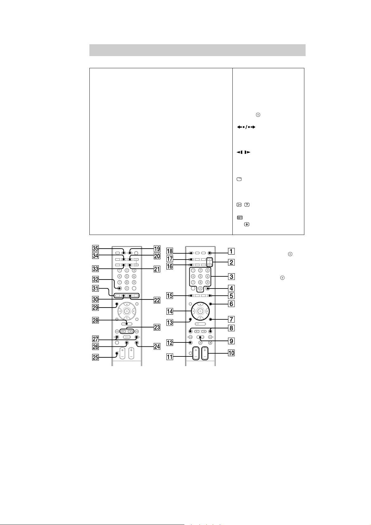
Remote control
ANALOG FE (83)
ANGLE (34)
AUDIO F (32, 35)
CLEAR FT (38, 50, 59)
D.TUNING XT (59)
DIGITAL XB (83)
DIMMER FE (86)
DISPLAY RI (60, 70, 86)
DVD MENU (41)
DVD TOP MENU XM (41)
DYNAMIC BASS XB (85)
ENTER* (24, 25, 36, 38, 58,
81)
FUNCTION +/– (28, 33)
MENU XL (83)
MUTING XH (33)
HCD-DZ370/DZ560/DZ570/DZ660/DZ777
Z–NM–A
NIGHT X (85)
ONE-TOUCH PLAY FH (63)
PICTURE NAVI RH (43, 67)
PRESET +/– (59)
PROG +/– (83)
S-AIR MODE RK (75)
SLEEP FG (85)
SOUND MODE +/– (32)
SUBTITLE XT (35)
SYSTEM MENU (24, 29, 85,
86, 75)
THEATRE RL (62)
TOOLS (83)
TUNING +/– XK (58)
TV RT (83)
TV VOL +/– RB (83)
VOLUME +/– RB (33)
SNOITPIRCSEDNOTTUBREDROLACITEBAHPLA
Number buttons (37, 58, 83)
Colored buttons FB (83)
</ (on/s
tandby) (24,
TV </ (on/standby) RM (83)
$/9/Y/D/ RG (24, 25, 36, 38,
58, 81)
XE (33)
/ (33)
N/. XK (33)
)(play) (33)
Y (stop) XG (33)
9 (pause) XI (33)
81)
0 RETURN RE (37, 83)
-/-- (83)
FT (83)
U/ (83)
D/$ (83)
REPLAY/ADVANCE
/ XK (33)
DISPLAY** XL (25, 36, 38,
/ RI (83)
XM (83)
25, 33)
110
* The ENTER button has the
same function as the
button. When you operate
the TV, the ENTER button
is used for selecting a
channel, and the button
is used for selecting menu
items (page 83).
** This button is available for
the “DVD,” “USB,” or
“DMPORT” function.
Depending on the
DIGITAL MEDIA PORT
adapter, this button may not
work.
GB
19
HCD-DZ370/DZ560/DZ570/DZ660/DZ777
Index to Parts and Control
(DZ777)
For more information, refer to the pages indicated in parentheses.
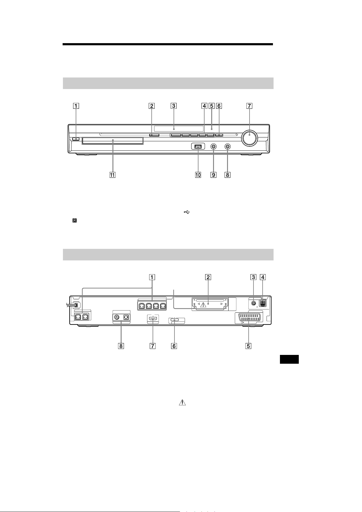
Front panel
" / (on/standby) (29, 93)
# " (open/close) (37)
$ Front panel display (113)
% Play operation buttons (37)
& (remote sensor) (9)
' FUNCTION (32)
( VOLUME control (37)
) PHONES jack (37)
* AUDIO IN/A.CAL MIC jack (25, 29, 86)
+ (USB) port (69)
, Disc tray (37)
Additional Information
Rear panel
SPEAKER
FRONTR FRONTL SUR R SUR L
SPEAKER
CENTER SUBWOOFER
" SPEAKER jacks (22)
# EZW-T100 slot (25)
$ COAXIAL 75Ω FM jack (27)
% AM terminal (27)
& SAT/CABLE (AUDIO IN R/L) jacks (25)
' TV (AUDIO IN R/L) jacks (23)
DIGITAL IN
COAXIAL OPTICAL
TUOIMDHVT
Screws*
EZW-T100
DC5V
DMPORT
0.7A MAX
B/CBPR/CR
Y
P
COMPONENTVIDEO OUT
VIDEO OUT TV
AUDIO IN
LR
( VIDEO OUT jack (23)
) COMPONENT VIDEO OUT jacks (23)
* DMPORT (DIGITAL MEDIA PORT) jack
(25, 78)
+ HDMI OUT jack (23)
, TV (DIGITAL IN COAXIAL/OPTICAL)
jacks (23)
* CAUTION
Please do not remove the screws before
installing the EZW-T100.
AUDIO IN LR
SAT/CABLE
ANTENNA
COAXIAL 75
FM
AM
20

HCD-DZ370/DZ560/DZ570/DZ660/DZ777
Front panel display
About the indications in the front panel display
" Playing status
# Flashes when the sleep timer is set.
(89)
$ Displays system’s status such as
chapter, title, or track number, time
information, radio frequency, playing
status, decoding mode, etc.
% Lights up when a station is received.
(Radio only) (63)
& Stereo/Monaural effect (Radio only)
(64)
' Lights up when the S-AIR transmitter
(not supplied) is inserted in the unit
and the system transmits the sound.
(79)
( Lights up when the HDMI OUT jack is
correctly connected to HDCP (Highbandwidth Digital Content Protection)
compliant device with HDMI or DVI
(Digital Visual Interface) input. (23)
) Current surround format (Except for
JPEG image file)
* Lights up when the color system is set
to NTSC. (Asian, Australian, and Middle
Eastern models only)
+ Lights up during USB recording/
copying. (75)
, Lights up when Super Audio CD/CD is
loaded. (40)
Additional Information
113
GB
21
HCD-DZ370/DZ560/DZ570/DZ660/DZ777
Remote control
Z–NM–A
ANALOG FE (87)
ANGLE (38)
AUDIO F (36, 39)
CLEAR FT (42, 54, 64)
D.TUNING XT (64)
DIGITAL XB (87)
DIMMER FE (90)
DISPLAY RI (65, 74, 90)
DVD MENU (45)
DVD TOP MENU XM (45)
DYNAMIC BASS XB (89)
ENTER* (28, 29, 40, 42, 63,
85)
FUNCTION +/– (32, 37)
MENU XL (87)
MUTING XH (37)
NIGHT X (89)
ONE-TOUCH PLAY FH (67)
PICTURE NAVI RH (47, 71)
PRESET +/– (64)
PROG +/– (87)
S-AIR MODE RK (79)
SLEEP FG (89)
SOUND MODE +/– (36)
SUBTITLE XT (39)
SYSTEM MENU (28, 33, 89,
90, 79)
THEATRE RL (66)
TOOLS (87)
TUNING +/– XK (63)
TV RT (87)
TV VOL +/– RB (87)
VOLUME +/– RB (37)
SNOITPIRCSEDNOTTUBREDROLACITEBAHPLA
Number buttons (41, 63, 87)
Colored buttons FB (87)
</ (on/s
tandby) (28,
TV </ (on/standby) RM (87)
$/9/Y/D/ RG (28, 29, 40, 42,
63, 85)
XE (37)
/ (37)
N/. XK (37)
)(play) (37)
Y (stop) XG (37)
9 (pause) XI (37)
85)
0 RETURN RE (41, 87)
-/-- (87)
FT (87)
U/ (87)
D/$ (87)
REPLAY/ADVANCE
/ XK (37)
DISPLAY** XL (29, 40, 42,
/ RI (87)
XM (87)
29, 37)
114
* The ENTER button has the
same function as the
button. When you operate
the TV, the ENTER button
is used for selecting a
channel, and the button
is used for selecting menu
items (page 87).
** This button is available for
the “DVD,” “USB,” or
“DMPORT” function.
Depending on the
DIGITAL MEDIA PORT
adapter, this button may not
work.
GB
22
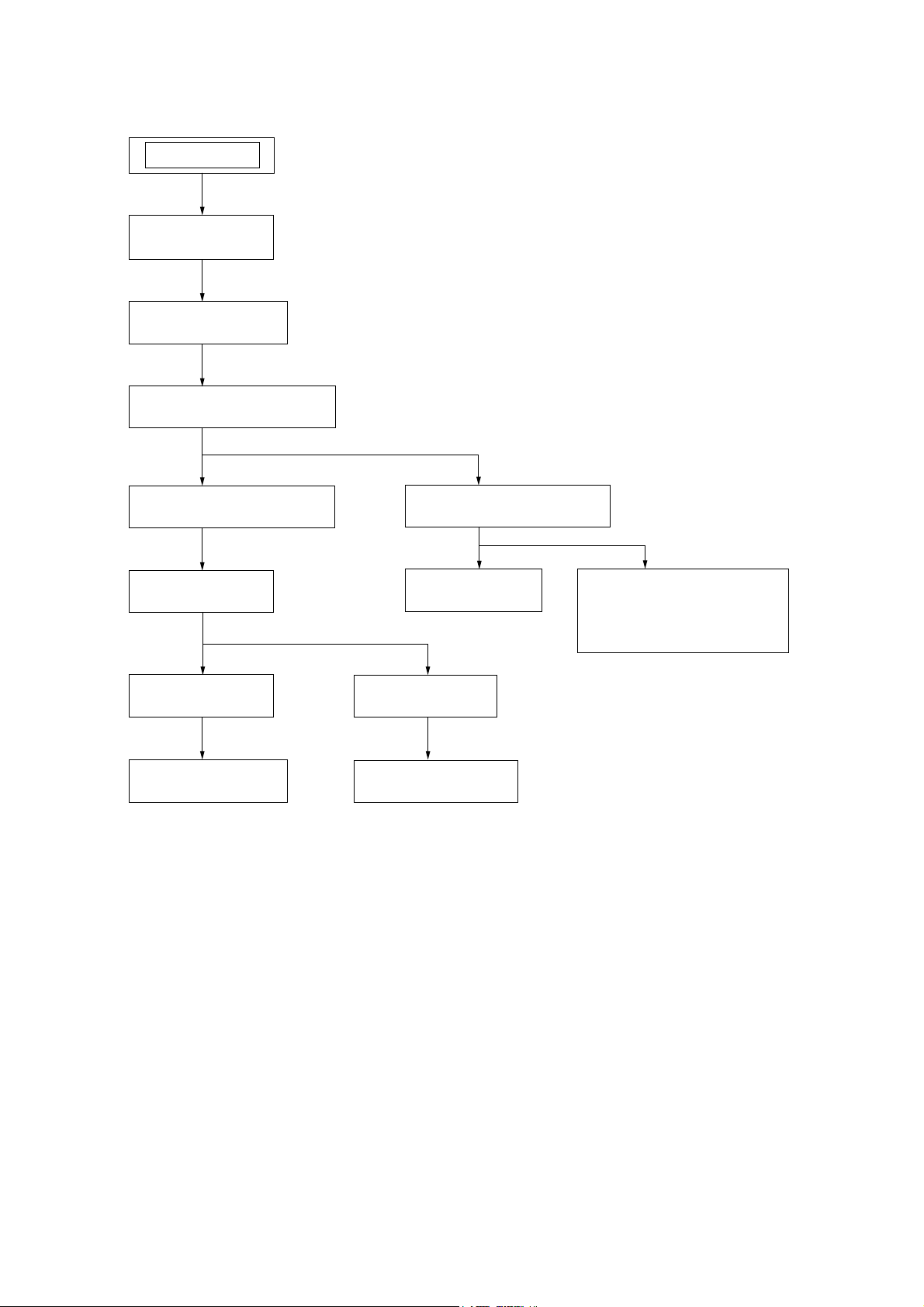
DISASSEMBLY
• This set can be disassembled in the order shown below.
SET
3-1. CASE
(Page 24)
3-2. POWER BOARD
(Page 24)
3-3. FRONT PANEL SECTION
(Page 25)
HCD-DZ370/DZ560/DZ570/DZ660/DZ777
SECTION 3
3-5. DVD MECHANISM DECK
(Page 26)
3-8. TRAY
(Page 27)
3-9. BELT
(Page 28)
3-10. MS-203 BOARD
(Page 28)
3-4. BACK PANEL SECTION
(Page 25)
3-6. MAIN BOARD
(Page 26)
3-11. BASE UNIT
(Page 29)
3-12. OPTICAL PICK-UP
(Page 29)
3-7. IO-SCART BOARD
(DZ560/DZ660)
IO-COMPONENT BOARD
(DZ370/DZ570/DZ777)
(Page 27)
23
HCD-DZ370/DZ560/DZ570/DZ660/DZ777
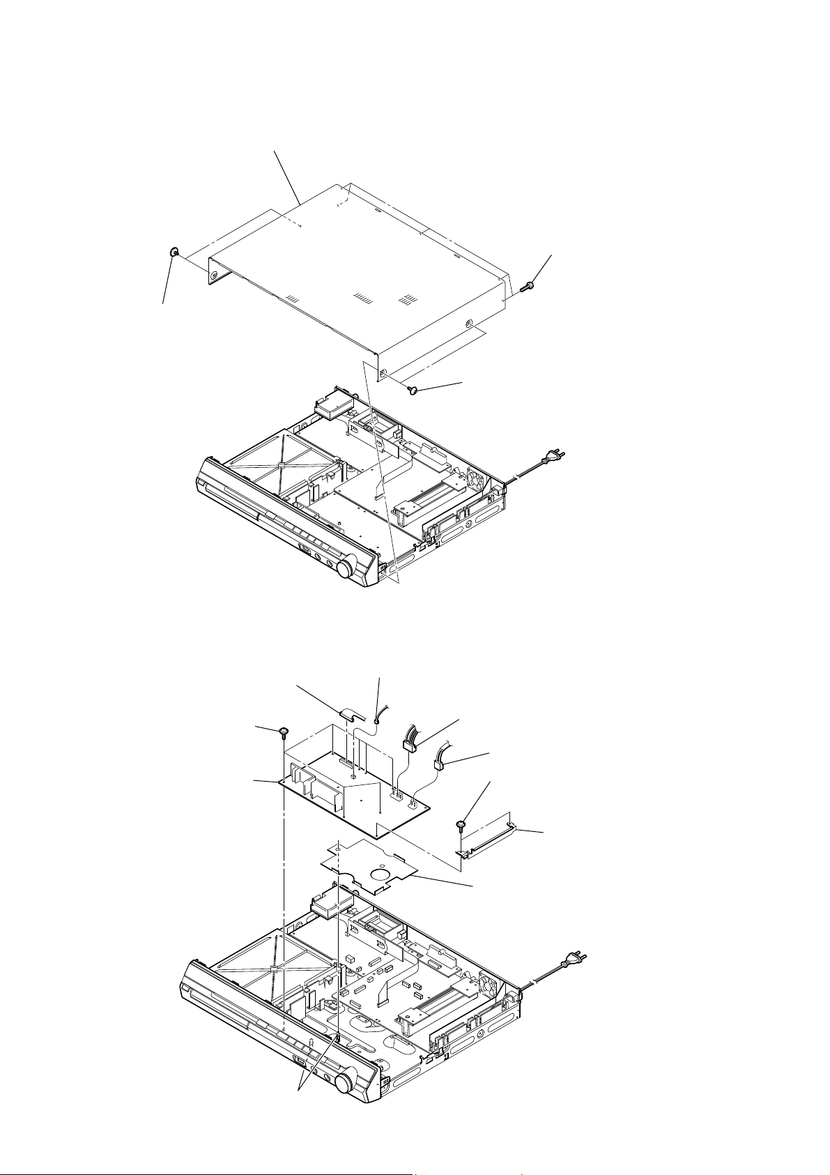
Note: Follow the disassembly procedure in the numerical order shown below.
3-1. CASE
case
five screws
(BV/RING)
two screws
(case 3 TP2)
two screws
(case 3 TP2)
3-2. POWER BOARD
seven screws
(+PWH 3 × 8)
POWER board
CN906 (13P)
CN908 (2P)
CN904 (4P)
CN901 (2P)
two screws
(+PWH 3 × 8)
shield plate (HP)
cover (USB)
24
two claws
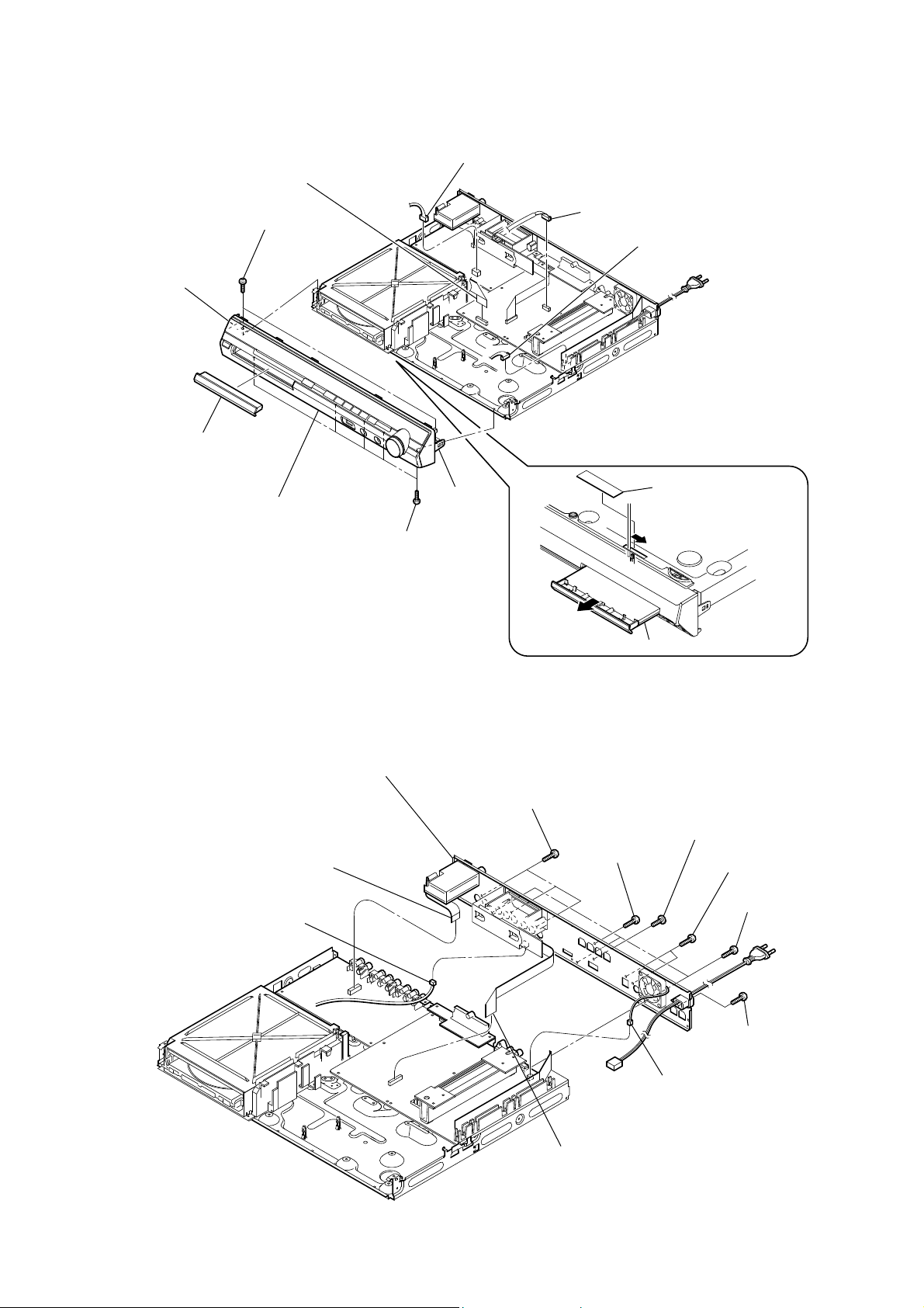
3-3. FRONT PANEL SECTION
HCD-DZ370/DZ560/DZ570/DZ660/DZ777
RB claw
loading panel
wire (flat type)(19 core)
(CN502)
two screws
(+BV3 (3-CR))
RT front panel section
CN412 (4P)
RB claw
five screws
(+BV3 (3-CR))
CN2101 (5P)
CN3001 (4P)
label
3-4. BACK PANEL SECTION
wire (flat type) (11 core) (CN414)
(DZ560/DZ660)
wire (flat type) (9 core) (CN419)
(DZ370/DZ570/DZ777)
CN110 (4P)
RB back panel section
three screws
(+BVTP 3 × 8)
tray
screw
(+BVTP 3 × 8)
screw
(+B 3 × 6)
two screws
(+BVTP 3 × 8)
three screws
(+BVTP 3 × 8)
screw
(+BVTP 3 × 8)
CN3000 (2P)
wire (flat type) (17 core)
(CN651)
25

HCD-DZ370/DZ560/DZ570/DZ660/DZ777
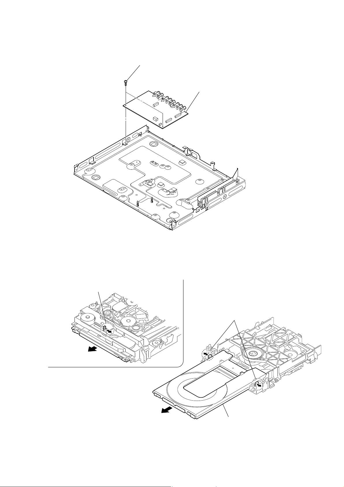
3-5. DVD MECHANISM DECK
screw
(+BV3 (3-CR))
cover (CDM-DSR)
two screws
(+BV3 (3-CR))
DVD mechanism deck
screw
(+BV3 (3-CR))
screw
(+BV3 (3-CR))
screw
(+BV3 (3-CR))
wire (flat type)(5 core)
(CN1202)
CN1201 (6P)
wire (flat type)(24 core)
(CN1101)
3-6. MAIN BOARD
wire (flat type) (19 core) (CN4301) (DZ560/DZ660)
wire (flat type) (17 core) (CN4302) (DZ370/DZ570/DZ777)
wire (flat type)(5 core)
(CN702)
wire (flat type) (19 core) (CN602)
(DZ560/DZ660)
wire (flat type) (17 core) (CN603)
(DZ370/DZ570/DZ777)
RT six screws
(+BV3 (3-CR))
RE MAIN board
screw
(+BVTP 3 × 12)
two screws
(+BV3 (3-CR))
heat sink section
two screws
(+BV3 (3-CR))
SPEAKER board
CN114 (8P)
two radiation sheet
RB two screws
(+BV3 (3-CR))
26
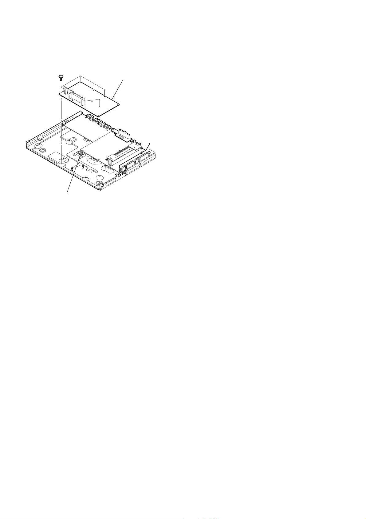
HCD-DZ370/DZ560/DZ570/DZ660/DZ777
3-7. IO-SCART BOARD (DZ560/DZ660), IO-COMPONENT BOARD (DZ370/DZ570/DZ777)
two screws
(+BV3 (3-CR))
IO-SCART board (DZ560/DZ660)
IO-COMPONENT board (DZ370/DZ570/DZ777)
3-8. TRAY
Move the chuck cam
in the direction of the arrow.
bottom side
two claws
tray
27
HCD-DZ370/DZ560/DZ570/DZ660/DZ777
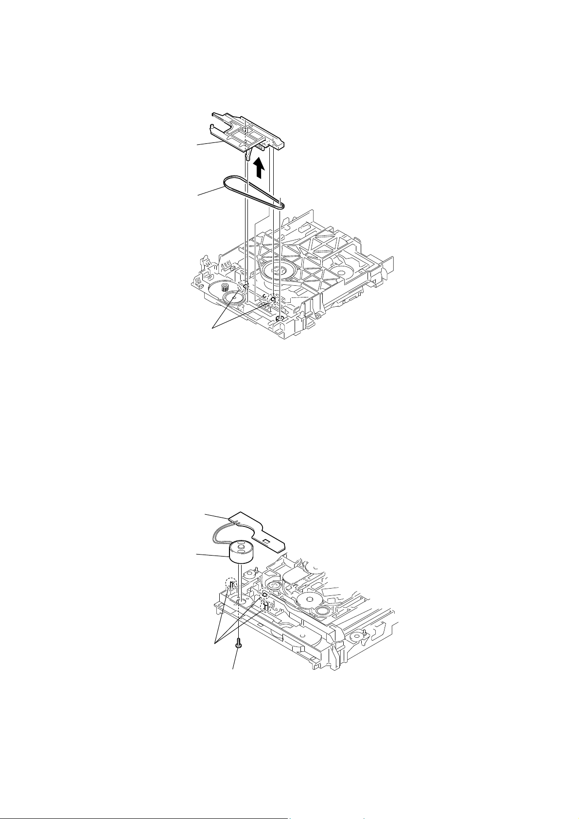
3-9. BELT
chuck cam
belt
3-10. MS-203 BOARD
MS-203 board
DC motor
two claws
28
three claws
screw
(M 1.7 × 2.5)
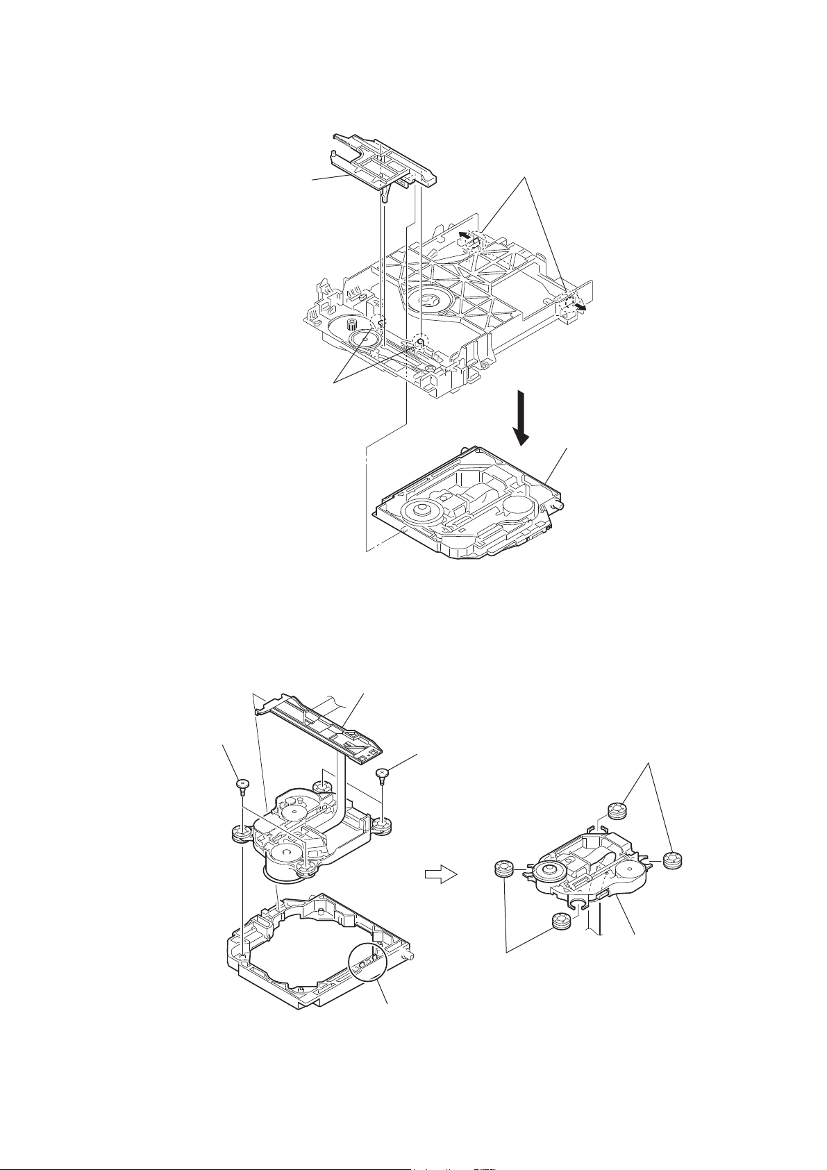
3-11. BASE UNIT
HCD-DZ370/DZ560/DZ570/DZ660/DZ777
chuck cam
two claws
two claws
base unit
3-12. OPTICAL PICK-UP
two insulator screws
FFC holder
two insulator screws
two claws
two insulators
optical pick-up
two insulators
29

HCD-DZ370/DZ560/DZ570/DZ660/DZ777
SECTION 4
TEST MODE
Note: Incorrect operations may be performed if the test mode is not
entered properly.
In this case, press the [?/1] button to turn the power off, and
retry to enter the test mode.
1. Cold Reset
• The cold reset clears all data including preset data stored in the
RAM to initial conditions. Execute this mode when returning
the set to the customers.
Procedure:
1. Press the [
2. Press three buttons [x], [A] and [
] button to turn the power on.
?/1
] simultaneously.
?/1
3. When this button is operated, display as “COLD RESET” for
a while and all of the settings are reset.
2. Panel Test Mode
• This mode is used to check the software version, FL and
KEY.
2-1. Display Test Mode
Procedure:
1. Press the [
2. Press three buttons [
] button to turn the power on.
?/1
], [.] and [A] simultaneously.
X
3. When the display test mode is activated, all segments are turned
on.
4. To exit from this mode, press three buttons [X], [.] and [A]
simultaneously.
2-2. Version Test Mode
Procedure:
1. When the display test mode is activated, press the [.]
button and the message “DSR3” (DZ370), “DSR4E” (DZ560),
“DSR4” (DZ570), “DSR7E” (DZ660), “DSR7” (DZ777) are
displayed, the version test mode is activated.
2. Whenever the [.] button is pressed, the display changes in
the following order.
“DSR7” (Model name) U“EA3*1” (Destination) U
UMC Version U SYS Version UUI Version U
UDVD Version UST Version U TA Version U
UDSP Version UTM Version UMM Version U
U CLA Version UCEC Version USAIR Version
*1: EA3 changes depending on destination.
3. Press the [>] button and the date of the software production
is displayed.
4. Press the [>] button again and the version is displayed.
5. To exit from this mode, press three buttons [X], [.] and [A]
simultaneously.
2-3. Key Test Mode
Procedure:
1. When the display test mode is activated, press the [H] button,
to select the key test mode.
2. To enter the KEY test mode, the fl uorescent indicator displays
“K0 V0”. Each time an another button is pressed, “KEY” value
increases. However, once a button is pressed, it is no longer
taken into account. When all keys are pressed correctly, “K8
V0” is displayed.
3. When the [VOLUME] control is turned in the direction of (+),
“V0” is changed to “V1”, then ... “V9”.
When the [VOLUME] control is turned in the direction of (–),
“V0” is changed to “V9”, then ... “V1”.
4. To exit from this mode, press three buttons [X], [.] and [A]
simultaneously.
3. Disc Tray Lock
The disc tray lock function for the antitheft of an demonstration
disc in the store is equipped.
Setting Procedure :
1. Press the [
] button to turn the set on.
?/1
2. Press the [FUNCTION] button to set DVD function.
3. Insert a disc.
4. Press the [x] button and the [A] button simultaneously for fi ve
seconds.
5. The message “LOCKED” is displayed and the tray is locked.
Releasing Procedure :
1. Press the [x] button and the [A] button simultaneously for fi ve
seconds again.
2. The message “UNLOCKED” is displayed and the tray is
unlocked.
Note: When “LOCKED” is displayed, the tray lock is not released by
turning power on/off with the [?/1] button.
4. DVD Ship Mode
Use this mode when returning the set to the customer after repair.
Procedure:
1. Press the [
] button to turn the set on.
?/1
2. Press the [FUNCTION] button to set the function “DVD”.
3. Remove all discs, and then press two buttons [H] and [
?/1
simultaneously.
4. After a message “MECHA LOCK” h “PULL PLUG” is
displayed on the fl uorescent indicator tube, pull out the AC
plug.
5. To exit from this mode, press the [
] button to turn the set
?/1
on.
5. AM Step Change (Except AEP, UK, E models)
• A step of AM channels can be changed over between 9 kHz
and 10 kHz.
Procedure:
1. Press the [
] button to turn the set ON.
?/1
2. Select the function “TUNER”, and press [FUNCTION] button
to select the BAND “AM”.
3. Press the [
4. Press two buttons [>] and [
] button to turn the set OFF.
?/1
?/1
] simultaneously, and the
display of fl uorescent indicator tube changes to “AM 9k STEP”
or “AM 10k STEP”, and thus the channel step is changed
over.
6. Product Out
This mode moves the optical pick-up to the position durable to
vibration and clears all data including preset data stored in the
RAM to initial conditions. Use this mode when returning the set to
the customer after repair.
Procedure:
1. Press the [
] button to turn the power on.
?/1
2. Press the [FUNCTION] button to set the function “DVD”.
3. Remove all discs, and then press three buttons [>], [A] and
[
] simultaneously.
?/1
4. After the “STANDBY” blinking display fi nishes, the message
“MECHA LOCK” h “PULL PLUG” is displayed on the
fl uorescent indicator tube disconnect the AC power plug, then
the ship mode is set.
]
30
 Loading...