

Sony HCD-DZ11O, HCD-DZ111, HCD-DZ120, HCD-DZ120K Servise Manual
AUDIO POWER SPECIFICATIONS
for the US model
POWER OUTPUT AND
TOTAL HARMONIC
DISTORTION
(FTC Output Power): FL/FR/LS/RS/C: 84 W/ch
3 ohm at 180 - 20,000 Hz,
0.7 % THD
SW: 80 W 3 ohm at 40 180 Hz, 0.7 % THD
US models:
Surround mode (reference)
RMS output power, 10 %
THD
Front: 142 W + 142 W
(with SS-TS51)
Center*: 142 W
(with SS-CT51)
Surround*: 142 W + 142
W
(with SS-TS51)
Subwoofer*: 140 W
(with SS-WS52)
Other models:
Stereo mode (rated) 108 W + 108 W (3 ohms at
1 kHz, 1 % THD)
Surround mode (reference)
RMS output power, 10 %
THD
Front: 142 W + 142 W
(with SS-TS51)
Center*: 142 W
(with SS-CT51)
Surround*: 142 W + 142
W
(with SS-TS51)
Subwoofer*: 140 W
(with SS-WS52)
Amplifier section
DZ110
Stereo mode (rated) 108 W + 108 W (3 ohms at
1 kHz, 1 % THD)
Surround mode (reference) RMS output power, 10 %
THD
Front: 142 W + 142 W
(with SS-TS51)
Center*: 142 W
(with SS-CT51)
Surround*: 142 W + 142 W
(with SS-TS51)
Subwoofer*: 140 W
(with SS-WS51)
DZ111
DZ120
DZ120
Stereo mode (rated) 108 W + 108 W (3 ohms at
1 kHz, 1 % THD)
Surround mode (reference) RMS output power, 10 %
THD
Front: 142 W + 142 W
(with SS-TS31A)
Center*: 142 W
(with SS-CT31A)
Surround*: 142 W + 142 W
(with SS-TS31A)
Subwoofer*: 140 W
(with SS-WS33)
DZ120K
Latin American models:
Stereo mode (rated) 100 W + 100 W (3 ohms at
1 kHz, 1 % THD)
Surround mode (reference)
RMS output power, 10 %
THD
Front: 133 W + 133 W
(with SS-TS51)
Center*: 133 W
(with SS-CT51)
Surround*: 133 W + 133
W
(with SS-TS51)
Subwoofer*: 135 W
(with SS-WS52)
HCD-DZ110/DZ111/
DZ120/DZ120K
Q
Q
3
7
6
3
1
5
1
5
0
SERVICE MANUAL
Ver. 1.4 2006.08
TEL 13942296513 QQ 376315150 892498299
HCD-DZ110/DZ111/DZ120/DZ120K are the amplifier, DVD/CD
and tuner section in DAV-DZ110/DZ111/DZ120/DZ120K.
This system incorporates with Dolby*1 Digital and Dolby Pro Logic (II)
adaptive matrix surround decoder and the DTS*2 Digital Surround
System.
*1 Manufactured under license from Dolby Laboratories.
“Dolby,” “Pro Logic,” and the double-D symbol are trademarks of
Dolby Laboratories.
*2 Manufactured under license from Digital Theater Systems, Inc.
“DTS” and “DTS Digital Surround” are trademarks of Digital
Theater Systems, Inc.
TEL
13942296513
Photo : HCD-DZ110
7
3
Q
Q
SPECIFICATIONS
8
9
2
4
9
8
2
9
9
US Model
Canadian Model
HCD-DZ120
AEP Model
HCD-DZ110/DZ120/DZ120K
UK Model
HCD-DZ110/DZ111
E Model
HCD-DZ120/DZ120K
Australian Model
HCD-DZ120
Model Name Using Similar Mechanism HCD-DZ100
Mechanism T ype CDM85-DVBU102
Optical Pick-up Name
5
1
5
1
3
6
0
8
9
2
4
KHM-310CAA
9
2
8
9
9
TEL 13942296513 QQ 376315150 892498299
w
w
w
9-887-019-05
2006H16-1
© 2006.08
.
Sony Corporation
Home Audio Division
Published by Sony Techno Create Corporation
xia
o
y
u
1
SUPER AUDIO CD/DVD RECEIVER
6
3
.
c
o
m
— Continued on next page —
HCD-DZ110/DZ111/DZ120/DZ120K
Ver. 1.3
7
DZ120K
Q
Q
Mexican and other models:
Stereo mode (rated) 108 W + 108 W (3 ohms at
Surround mode (reference)
*Depending on the sound field settings and the source ,
there may be no sound output.
TEL 13942296513 QQ 376315150 892498299
DZ110/DZ111
Inputs (Analog)
LINE (AUDIO IN) Sensitivity: 450/250 mV
Phones Accepts low-and high-
AUDIO IN Sensitivity: 250/125 mV
DZ120
Inputs (Analog)
TV/VCR (AUDIO IN) Sensitivity: 450/250 mV
AUDIO IN/MIC Sensitivity: 250/125 mV
Outputs (Analog)
Phones Accepts low-and high-
DZ120K
Inputs (Analog)
TEL
TV/VCR (AUDIO IN/VIDEO IN)
AUDIO IN/MIC 1/MIC
MIC 2 Sensitivity: 1 mV
3
13942296513
6
1 kHz, 1 % THD)
RMS output power, 10 %
THD
Front: 142 W + 142 W
(with SS-TS51)
Center*: 142 W
(with SS-CT51)
Surround*: 142 W + 142
W
(with SS-TS51)
Subwoofer*: 140 W
(with SS-WS52)
Impedance: 50 kilohms
impedance headphones.
Impedance: 50 kilohms
impedance headphones.
Sensitivity: 450/250 mV
Sensitivity: AUDIO IN
250/125 mV/MIC 1 1 mv
3
1
5
1
5
DVD system
Laser Semiconductor laser
S
ignal format system
European models:
Mexican and North American models:
Other models:
DZ110/DZ111
Frequency response (at 2 CH STEREO mode)
Harmonic distortion Less than 0.03 %
Tuner section
System PLL quartz-locked digital
FM tuner section
Tuning range
North American models: 87.5 – 108.0 MHz
Other models: 87.5 – 108.0 MHz
Antenna (aerial) FM wire antenna (aerial)
Antenna (aerial) terminals 75 ohms, unbalanced
Intermediate frequency 10.7 MHz
AM tuner section
Tuning range
North American models: 530 – 1,710 kHz (with the
Other models: 530 – 1,710 kHz (with the
Antenna (aerial) AM loop an tenna (aerial)
Intermediate frequency 450 kHz
0
(DVD: λ = 650 nm)
(CD: λ = 790 nm)
Emission duration:
continuous
PAL
NTSC
NTSC/PAL
DVD (PCM): 2 Hz to 22
kHz (±1.0 dB)
CD: 2 Hz to 20 kHz (±1.0
dB)
synthesizer system
(100 kHz step)
(50 kHz step)
interval set at 10 kHz)
531 – 1,710 kHz (with the
Q
interval set at 9 kHz)
interval set at 10 kHz)
531 – 1,602 kHz (with the
interval set at 9 kHz)
531 – 1,710 kHz (with the
interval set at 9 kHz)
Q
3
7
4
2
9
8
Video section
European models:
Outputs VIDEO: 1 Vp-p 75 ohms
Other models:
Outputs Video: 1 Vp-p 75 ohms
General
Power requirements
North American and Mexican models:
Taiwan model : 120 V AC, 50/60Hz
Latin American model : 110 - 240 V AC, 50/60Hz
Other models: 220 - 240 V AC, 50/60 Hz
Power consumption On: 150 W
Dimensions (approx.) 430 × 55 × 360 mm
Mass (approx.) 3.8 kg
Design and specifications are subject to change
without notice.
8
0
5
1
5
1
3
6
8
9
COMPONENT:
Y: 1 Vp-p 75 ohms
PB/CB, PR/CR: 0.7 Vp-p
75 ohms
S video:
Y: 1 Vp-p 75 ohms
C: 0.286 Vp-p 75 ohms
COMPONENT:
Y: 1 Vp-p 75 ohms
PB/CB, PR/CR: 0.7 Vp-p
75 ohms
120
V AC, 60 Hz
Standby: 0.3 W (at the
Power Saving Mode)
(17 × 2
(w/h/d) incl. projecting
parts
2
9
2
9
1
/4 × 14 1/4 inches)
2
8
9
4
9
9
TEL 13942296513 QQ 376315150 892498299
9
MODEL IDENTIFICATION
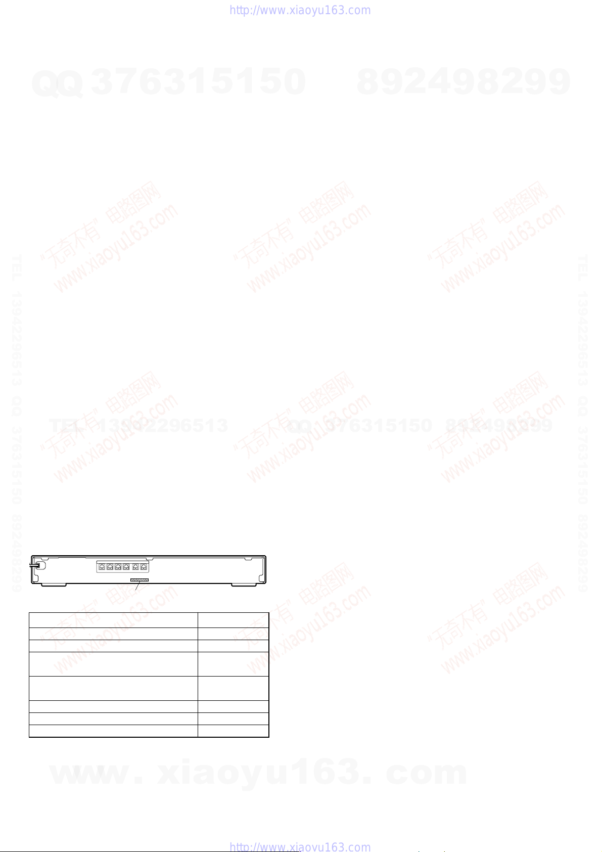
– Rear Panel –
SPEAKER
FRONT R FRONT L SUR R SUR LCENTER
WOOFER
Parts No.
Model Part No.
DZ110 : AEP, UK models 2-653-933-0[]
DZ111 : UK model 2-653-933-1[]
DZ120 : AUS, RU models
DZ120K : SP, E12, E32, AR, KR, TW models
DZ120 : US, CND models/
DZ120K : MX model
DZ120K : E3 model 2-653-933-5[]
DZ120K : RU model 2-661-239-2[]
DZ120K : EA model 2-661-239-3[]
w
w
w
.
xia
2-653-933-2[]
2-653-933-3[]
o
y
•Abbreviation
AUS: Australian Model
AR : Argentina model
CND : Canadian Model
E3 : 240V AC area in E model
E12 : 220-240V AC area in E model
E32 : 110-240V AC area in E model
EA : Saudi Arabia model
KR : Korean model
MX : Mexican model
RU : Russian model
SP : Singapore model
TW : Taiwan model
u
1
6
3
.
c
o
m
2
r
HCD-DZ110/DZ111/DZ120/DZ120K
Q
TEL 13942296513 QQ 376315150 892498299
SAFETY CHECK-OUT
Q
After correcting the original service problem, perform the following
safety check before releasing the set to the customer:
Check the antenna terminals, metal trim, “metallized” knobs, screws,
and all other exposed metal parts for AC leakage.
Check leakage as described below.
LEAKAGE TEST
The AC leakage from any exposed metal part to earth ground and
from all exposed metal parts to any exposed metal part having a
return to chassis, must not exceed 0.5 mA (500 microamperes.).
Leakage current can be measured by any one of three methods.
1. A commercial leakage tester, such as the Simpson 229 or RCA
2. A battery-operated AC milliammeter . The Data Precision 245
3. Measuring the voltage drop across a resistor by means of a
7
3
WT -540A. Follow the manufactur ers’ instructions to use these
instruments.
digital multimeter is suitable for this job.
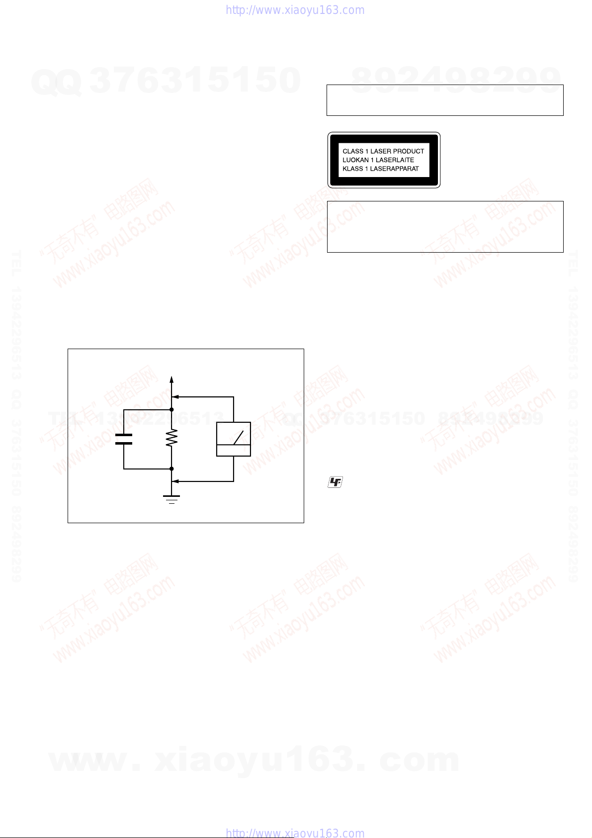
VOM or battery-operated AC v oltmeter. The “limit” indication
is 0.75 V, so analog meters must hav e an accurate low-voltage
scale. The Simpson 250 and Sanwa SH-63Trd are examples
of a passive VOM that is suitable. Nearly all battery operated
digital multimeters that have a 2 V AC range are suitable. (See
Fig. A)
6
To Exposed Metal
Parts on Set
3
1
5
1
5
0
Laser component in this product is capable of emitting radiation
exceeding the limit for Class 1.
CAUTION
Use of controls or adjustments or performance of procedures
other than those specified herein may result in hazardous radiation
exposure.
Notes on chip component replacement
• Never reuse a disconnected chip component.
• Notice that the minus side of a tantalum capacitor may be
Flexible Circuit Board Repairing
• Keep the temperature of the soldering iron around 270 °C
• Do not touch the soldering iron on the same conductor of the
• Be careful not to apply force on the conductor when soldering
4
2
9
8
damaged by heat.
during repairing.
circuit board (within 3 times).
or unsoldering.
9
2
8
This appliance is classified as
a CLASS 1 LASER product.
This marking is located on
the bottom exterior.
9
9
TEL 13942296513 QQ 376315150 892498299
TEL
13942296513
AC
1.5 k
0.15 µF
Fig. A. Using an AC voltmeter to check AC leakage.
SAFETY-RELATED COMPONENT WARNING!!
COMPONENTS IDENTIFIED BY MARK 0 OR DOTTED LINE
WITH MARK 0 ON THE SCHEMATIC DIAGRAMS AND IN
THE PARTS LIST ARE CRITICAL TO SAFE OPERATION.
REPLACE THESE COMPONENTS WITH SONY PARTS WHOSE
PART NUMBERS APPEAR AS SHOWN IN THIS MANUAL OR
IN SUPPLEMENTS PUBLISHED BY SONY.
Ω
Earth Ground
voltmete
(0.75 V)
Q
Q
UNLEADED SOLDER
6
7
3
Boards requiring use of unleaded solder are printed with the leadfree mark (LF) indicating the solder contains no lead.
(Caution: Some printed circuit boards may not come printed with
: LEAD FREE MARK
Unleaded solder has the following characteristics.
• Unleaded solder melts at a temperature about 40 °C higher
than ordinary solder.
Ordinary soldering irons can be used but the iron tip has to be
applied to the solder joint for a slightly longer time.
Soldering irons using a temperature regulator should be set to
about 350 °C.
Caution: The printed pattern (copper foil) may peel away if
• Strong viscosity
Unleaded solder is more viscou-s (sticky, less prone to flow)
than ordinary solder so use caution not to let solder bridges
occur such as on IC pins, etc.
• Usable with ordinary solder
It is best to use only unleaded solder but unleaded solder may
also be added to ordinary solder.
5
1
3
the lead free mark due to their particular size)
the heated tip is applied for too long, so be careful!
1
5
0
8
9
2
4
9
8
2
9
9
ATTENTION AU COMPOSANT AYANT RAPPORT
LES COMPOSANTS IDENTIFIÉS PAR UNE MARQUE 0 SUR
LES DIAGRAMMES SCHÉMATIQUES ET LA LISTE DES
PIÈCES SONT CRITIQUES POUR LA SÉCURITÉ DE
FONCTIONNEMENT. NE REMPLACER CES COM- POSANTS
w
w
w
QUE PAR DES PIÈCES SONY DONT LES NUMÉROS SONT
DONNÉS DANS CE MANUEL OU DANS LES SUPPLÉMENTS
PUBLIÉS PAR SONY.
À LA SÉCURITÉ!
.
xia
o
y
u
1
6
3
.
c
o
m
3

HCD-DZ110/DZ111/DZ120/DZ120K
7
Q
Q
1. SERVICING NOTE ................................................... 5
2. GENERAL ................................................................... 8
3. DISASSEMBLY
3-1. Disassembly Flow ........................................................... 11
3-2. Case, Front Panel Assy .................................................... 12
3-3. FL Board.......................................................................... 13
3-4. JACK Board, SW Board .................................................. 13
3-5. I/O Board (DZ120/DZ120K), I/O SCART Board
(DZ110/DZ111)............................................................... 14
3-6. MAIN Board.................................................................... 14
3-7. DC Fan, Tuner Unit ......................................................... 15
TEL 13942296513 QQ 376315150 892498299
3-8. POWER Board ................................................................ 15
3-9. DVD Mechanism Deck (CDM85-DVBU102) ................ 16
3-10. Tray.................................................................................. 16
3-11. Belt, MS-203 Board ........................................................ 17
3-12. Optical Pick-up (KHM-310CAA) ................................... 18
4. TEST MODE ............................................................... 19
5. ELECTRICAL ADJUSTMENT ............................. 23
6. DIAGRAMS
6-1. Block Diagram – RF Section –....................................... 26
6-2. Block Diagram – AMP Section – ................................... 27
6-3. Block Diagram – AUDIO Section – ............................... 28
6-4. Block Diagram – VIDEO Section – ............................... 29
6-5. Block Diagram – POWER Section – .............................. 30
TEL
6-6. Printed Wiring Board – MAIN Board (Side A) –............ 31
6-7. Printed Wiring Board – MAIN Board (Side B) – ............ 32
6-8. Schematic Diagram – MAIN Board (1/10) – ................. 33
6-9. Schematic Diagram – MAIN Board (2/10) – ................. 34
3
13942296513
6
3
1
5
1
5
TABLE OF CONTENTS
0
6-10. Schematic Diagram – MAIN Board (3/10) – ................. 35
6-11. Schematic Diagram – MAIN Board (4/10) – ................. 36
6-12. Schematic Diagram – MAIN Board (5/10) – ................. 37
6-13. Schematic Diagram – MAIN Board (6/10) – ................. 38
6-14. Schematic Diagram – MAIN Board (7/10) – ................. 39
6-15. Schematic Diagram – MAIN Board (8/10) – ................. 40
6-16. Schematic Diagram – MAIN Board (9/10) – ................. 41
6-17. Schematic Diagram – MAIN Board (10/10) – ............... 42
6-18. Printed Wiring Board – I/O Board (DZ120/DZ120K) – . 43
6-19. Schematic Diagram – I/O Board (DZ120/DZ120K) –... 44
6-20. Printed W iring Board
6-21. Printed W iring Board
6-22. Schematic Diagram
6-23. Printed Wiring Board – PANEL Section – ...................... 48
6-24. Schematic Diagram – PANEL Section – ....................... 49
6-25. Printed Wiring Board – SPEAKER Board – ................... 50
6-26. Schematic Diagram – SPEAKER Board –.................... 50
6-27. Printed Wiring Board – MS-203 Board – ........................ 51
6-28. Schematic Diagram – MS-203 Board – ........................ 51
6-29. Printed Wiring Board – POWER Board – ....................... 52
6-30. Schematic Diagram – POWER Board –........................ 53
7. EXPLODED VIEWS
7-1. Overall Section ................................................................ 64
7-2. Front Panel Section ......................................................... 65
7-3. Chassis Section-1 ............................................................ 66
Q
7-4. Chassis Section-2 ............................................................ 67
7-5. DVD Mechanism Deck Section (CDM85-DVBU102) ... 68
8. ELECTRICAL PARTS LIST .................................. 69
– I/O SCART Board (Side A) (DZ110/DZ111) – ........... 45
– I/O SCART Board (Side B) (DZ110/DZ111) – ........... 46
– I/O SCART Board (DZ110/DZ111) –.......................... 47
7
3
Q
8
6
3
9
1
5
2
1
5
4
0
9
8
9
8
2
4
2
9
8
9
2
9
9
TEL 13942296513 QQ 376315150 892498299
9
4
w
w
w
.
xia
o
y
u
1
6
3
.
c
o
m
HCD-DZ110/DZ111/DZ120/DZ120K
SECTION 1
SERVICING NOTE
7
Q
Q
TEL 13942296513 QQ 376315150 892498299
TEL
3
NOTES ON HANDLING THE OPTICAL PICK-UP BLOCK
OR BASE UNIT
The laser diode in the optical pick-up block may suffer electrostatic
break-down because of the potential difference generated by the
charged electrostatic load, etc. on clothing and the human body.
During repair, pay attention to electrostatic break-down and also
use the procedure in the printed matter which is included in the
repair parts.
The flexible board is easily damaged and should be handled with
care.
NOTES ON LASER DIODE EMISSION CHECK
The laser beam on this model is concentrated so as to be focused on
the disc reflective surface by the objective lens in the optical pickup block. Therefore, when checking the laser diode emission,
observe from more than 30 cm away from the objective lens.
DISC TRA Y LOCK
The disc tray lock function for the antitheft of an demonstration
disc in the store is equipped.
Setting Procedure :
1. Press the ?/1 button to turn the set on.
2. Press the [FUNCTION] button to set DVD function.
3. Insert a disc.
4. Press the
seconds.
5. The message “LOCKED” is displayed and the tray is locked.
Releasing Procedure :
1. Press the x button and the A button simultaneously for fi ve
13942296513
seconds again.
2. The message “UNLOCKED” is displayed and the tray is
unlocked.
Note: When “LOCKED” is displayed, the tray lock is not released by
Note on MAIN board replacement
New part of EEP ROM (IC1103) on the MAIN board cannot be used.
Therefore, if the mounted MAIN board (A-1144-739-A, etc.) is replaced,
exchange new EEP ROM (IC1103) with that used before the replacement.
turning power on/off with the ?/1 button.
6
x button and the A button simultaneously for five
3
1
5
1
5
0
Q
Q
Self-diagnosis Function
(When letters/numbers appear in the
display)
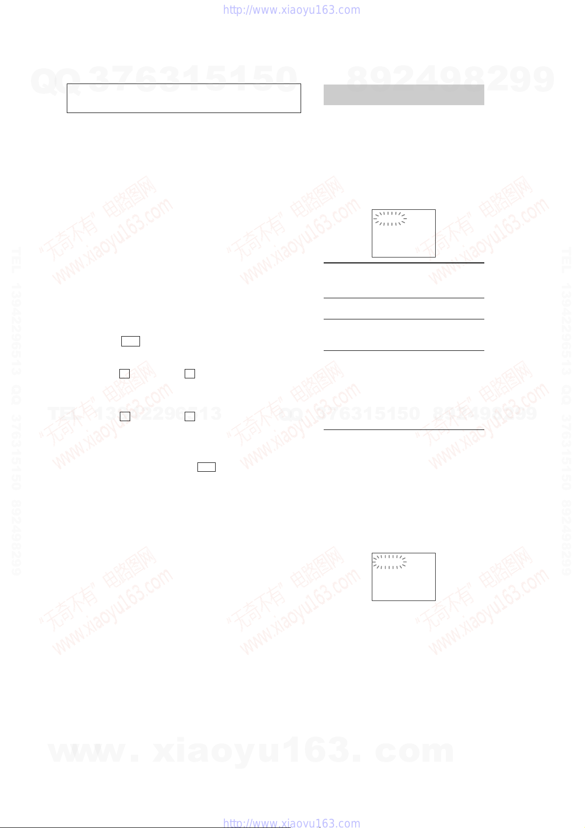
When the self-diagnosis function is activated to
prevent the system from malfunctioning, a 5character service number (e.g., C 13 50) with a
combination of a letter and 4 digits appears on
the screen and the front panel display. In this
case, check the following table.
First 3
characters of
the service
number
C 13 The disc is dirty.
C 31 The disc is not inserted correctly.
E XX
(xx is a number)
7
3
When displaying the version
number on the screen
When you turn on the system, the version
number [VER.X.XX] (X is a number) may
appear on the screen. Although this is not a
malfunction and for Sony service use only,
normal system operation will not be possible.
Turn off the system, and then turn on the system
again to operate.
8
6
4
2
9
C:13:50
Cause and/or corrective action
,Clean the disc with a soft cloth
,Restart the system, then re-insert
the disc correctly.
To prevent a malfunction, the
system has performed the selfdiagnosis function.
,Contact your nearest Sony
dealer or local authorized Sony
service facility and give the 5character service number.
0
5
1
5
1
3
Example: E 61 10
9
8
9
8
2
4
2
9
8
9
2
9
9
TEL 13942296513 QQ 376315150 892498299
9
w
w
w
.
xia
o
y
u
1
6
3
.
VER.X.XX
c
o
m
5
F
HCD-DZ110/DZ111/DZ120/DZ120K
7
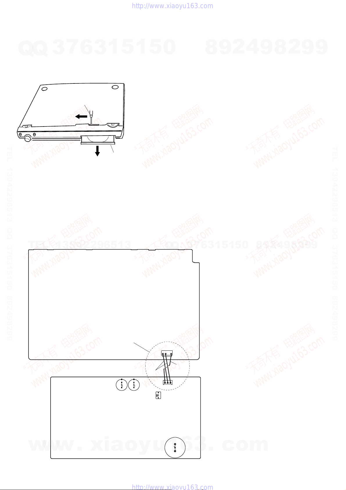
HOW TO OPEN THE DISC TABLE WHEN POWER SWITCH TURNS OF
Q
Q
Insert a tapering driver into the aperture of the unit bottom, and slide
it in the direction of the arrow.
TEL 13942296513 QQ 376315150 892498299
Discharge the charged electricity in capacitors to prevent electric shock as follows
When disassembling the machine, be sure to discharge the charged electricity in the following capacitors.
Use a resistor of 800 ohms, 2 Watts for discharging the following capacitors.
POWER board
C903 : 600V
C932, C933, C939, CN902 : 30V
3
tapering driver
6
3
1
disc tray
5
1
5
0
8
9
2
4
9
8
2
9
9
TEL 13942296513 QQ 376315150 892498299
MAIN board
CN3002 : 30 V
MAIN BOARD
TEL
(Parts face side)
13942296513
*
Connect the specified resistor
between black and red leads
POWER BOARD
(Parts face side)
C932
C933
RED
C939
Q
CN3002
Q
CN902
BLACK
3
7
6
3
1
5
1
5
0
8
9
2
4
9
8
2
9
9
6
w
w
w
.
xia
C903
o
y
u
1
6
3
.
c
o
m
Y
HCD-DZ110/DZ111/DZ120/DZ120K
7
3
Q
TEL 13942296513 QQ 376315150 892498299
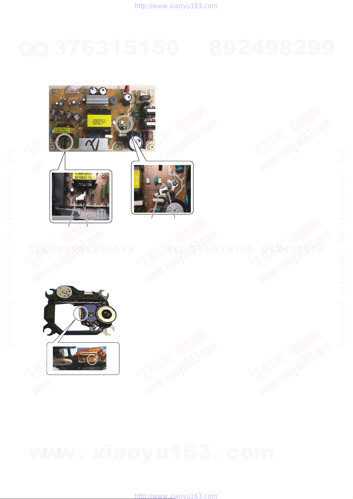
Fix the capacitors with adhesive agent as follows
Q
Fixing the capacitors with adhesive agent is required by the safety regulation.
Be sure to fix the capacitors with adhesive agent when part or circuit board is replaced.
POWER BOARD
C924 IC921
6
3
1
5
1
C910
5
0
C930
8
9
2
4
9
8
2
9
9
TEL 13942296513 QQ 376315150 892498299
TEL
13942296513
PRECAUTION WHEN INSTALLING A NEW OP UNIT /
PRECAUTION BEFOR UNSOLDERING THE STATIC ELECTRICIT
PREVENTION SOLDER BRIDGE
Q
Q
%%
When installing a new OP unit, be sure to connect the flexible
printed circuit board first of all before removing the static electricity
prevention solder bridge by unsoldering. Remove the static electricity
prevention solder bridge by unsoldering after the flexible printed
circuit board has already been connected.
(Do not remove nor unsolder the solder bridge
as long as the OP unit is kept standalone.)
3
7
6
3
1
5
1
5
0
8
9
2
4
9
8
2
9
9
w
w
w
.
xia
o
y
u
1
6
3
.
c
o
m
7
HCD-DZ110/DZ111/DZ120/DZ120K
SECTION 2
GENERAL
This section is extracted
from instruction manual.
7
Q
Q
TEL 13942296513 QQ 376315150 892498299
3
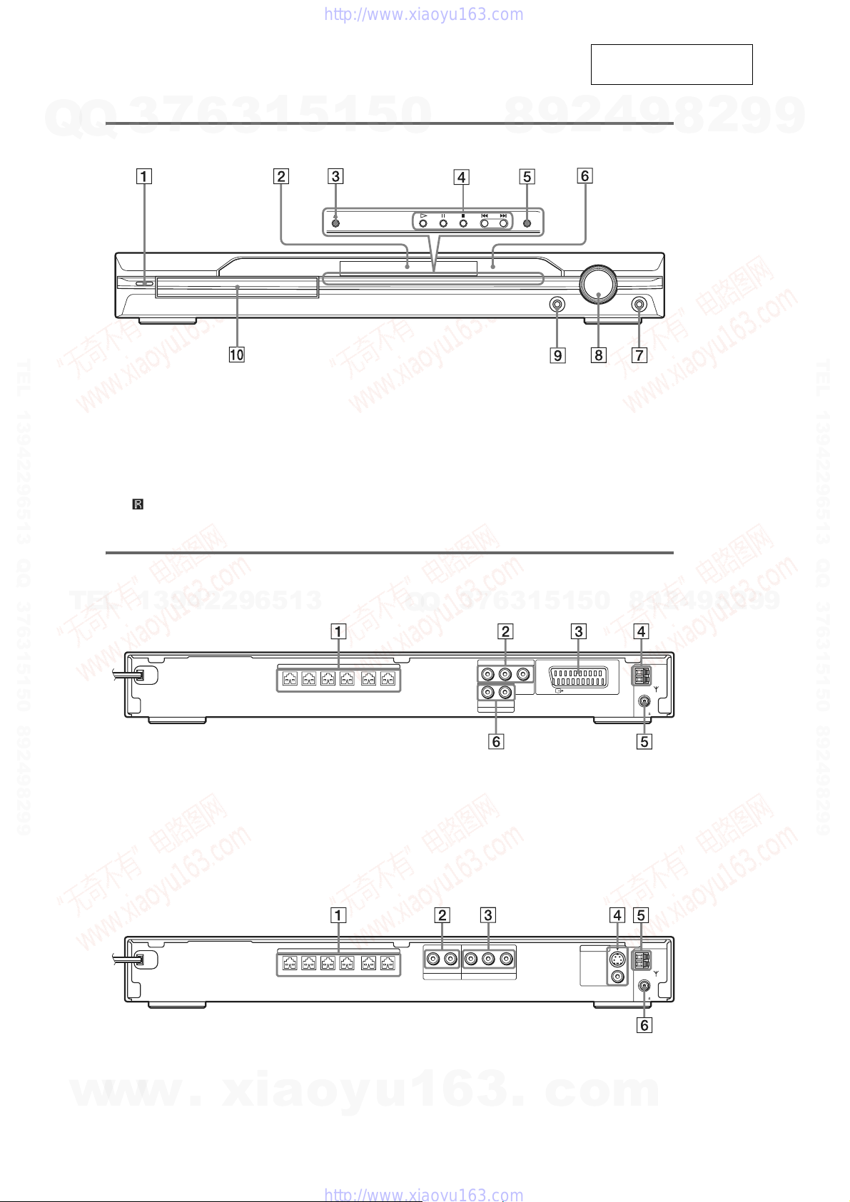
Front panel
A "/1 (on/standby) (23)
B Front panel display (83)
C A (open/close) (23)
D Disc operation (23)
E FUNCTION (23)
F (remote sensor) (8)
6
3
1
5
1
5
0
G PHON
H VOLUME control (23)
I AUDIO IN ja
J Disc tray (23)
ES jack (23)
MIC 2 jack (DZ120K)
AUDIO IN/A.CAL MIC jack (DZ120)
AUDIO IN/MIC 1/A.CAL MIC jack (DZ120K)
9
8
ck (15, 24)
2
4
9
8
2
9
9
TEL 13942296513 QQ 376315150 892498299
DZ110/DZ111
Rear panel
TEL
13942296513
FRONT R FRONT L SUR R SUR LCENTER WOOFER
A SPEAKER jacks (9)
B COMPONENT VIDEO OUT jacks (19)
C EURO AV T OUTPUT (TO TV) jack (9,
19)
DZ120/DZ120K
Rear panel
FRONT R FRONT L SUR R SUR LCENTER WOOFER
SPEAKER
SPEAKER
0
5
1
5
1
3
6
7
3
Q
Q
COMPONENT VIDEO OUT
YPB/CBPR/C
R
(DVD ONLY)
RLAUDIO IN
LINE
D AM terminal (9)
E COAXIAL FM 75Ω jack (9)
F LINE (AUDIO IN R/L) jacks (22)
RLAUDIO IN
YPB/CBPR/C
R
(DVD ONLY)
COMPONENT VIDEO OUT
TV/VCR
EURO AV
OUTPUT(TO TV)
MONITOR OUT
S VIDEO
(DVD ONLY)
VIDEO
8
COAXIAL
FM
COAXIAL
FM
9
75
75
9
9
2
8
9
4
2
AM
AM
8
A SPEAKER jacks (10)
B TV/VCR (AUDIO IN R/L) jacks (23)
C COMPONENT VIDEO OUT jacks (20)
w
w
w
.
xia
D MONITOR OUT (S VIDEO/VIDEO) jacks
(20)
o
y
E AM terminal (10)
u
1
6
3
F COAXIAL FM 75Ω jack (10)
.
c
o
m

HCD-DZ110/DZ111/DZ120/DZ120K
7
Q
Q
TEL 13942296513 QQ 376315150 892498299
TEL
3
13942296513
6
Front panel display
About the indications in the front panel display
A Lights up when the time information of
a title or chapter appears in the front
panel display. (DVD only) (46)
B Lights up when the color system is set
to NTSC. (Asian and Australian models
only) (17)
C Lights up when a station is received.
(Radio only) (59)
D Monaural/Stereo effect (Radio only)
(59)
E Lights up when the sleep timer is set.
(66)
F Lights up when the music or movie
mode is selected. (Except for JPEG)
(33)
G Lights up when the karaoke mode is
on. (DZ120K) (62)
3
1
5
1
5
0
Q
Q
H Lights up when the DYNAMIC BASS is
I Lights up when CD is loaded.
J Lights up when the system outputs
K Indicates the selected [SPEAKER
L Current surround format (Except for
M Playing status (DVD function only)
N Displays system’s status such as
7
3
4
2
9
8
selected. (66)
progressive signals (DVD function
only). (26)
FORMATION]. (71)
JPEG)
0
5
1
5
1
3
6
chapter, title, or track number, time
information, radio frequency, playing
status, sound field, etc.
9
8
9
2
8
4
2
9
8
9
2
9
9
TEL 13942296513 QQ 376315150 892498299
9
w
w
w
.
xia
o
y
u
1
6
3
.
c
o
m
9
HCD-DZ110/DZ111/DZ120/DZ120K
7
Q
Q
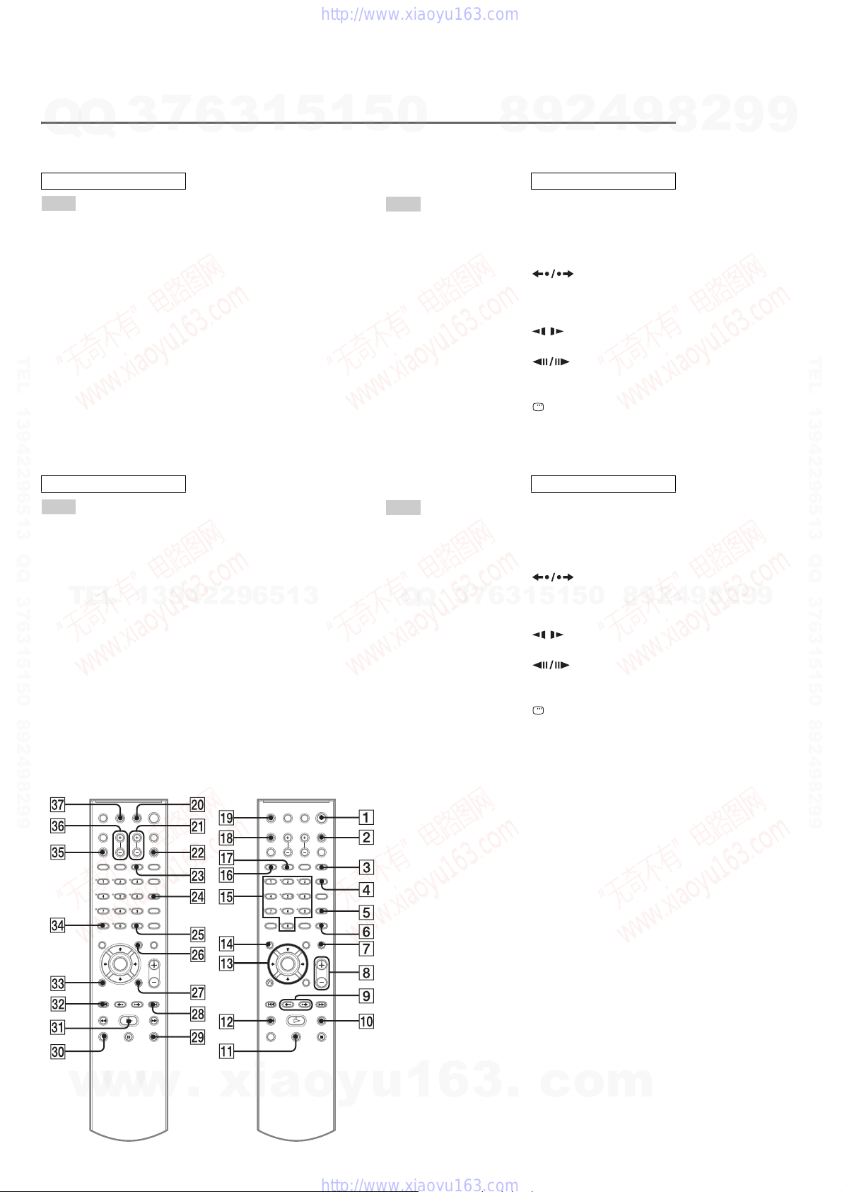
Remote control
DZ110/DZ111/DZ120
ALPHABETICAL ORDER
A – O
AMP MENU wg (17, 24, 54, 56,
88)
ANGLE 5 (41)
AUDIO 4 (36)
CLEAR ef (30, 54, 64)
D.TUNING wf (51)
DISC SKIP* qk
DISPLAY 3 (39, 52)
DYNAMIC BASS wd (55)
TEL 13942296513 QQ 376315150 892498299
ENTER qd (15, 17, 24, 30, 51, 54,
57)
FUNCTION ws (20, 23, 24, 31,
51, 60, 72)
DZ120K
ALPHABETICAL ORDER
A – O
AMP MENU wg (22, 32, 61, 67,
103)
ANGLE 5 (48)
AUDIO 4 (43)
CLEAR ef (37, 59, 61, 76)
D.TUNING wf (59)
TEL
DISPLAY 3 (46, 60)
DYNAMIC BASS wd (66)
ECHO qk (63)
ENTER qd (19, 22, 32, 37, 58,
68)
FUNCTION ws (26, 30, 31, 38,
58, 71)
KARAOKE MODE ej (62)
KARAOKE PON 2 (64)
KEYCON #/b wa (64)
3
13942296513
6
MENU wh (36, 51)
MOVIE/MUSIC qj (26)
MUTING 7 (23)
Number buttons** qg (30, 51, 54,
MENU wh (43, 58)
MIC VOL +/– eh (63)
MOVIE/MUSIC qj (33)
MUTING 7 (30)
Number buttons** qg (37, 59, 61,
3
57)
68)
1
5
1
5
0
P – Z
PICTURE NAVI 6 (31, 54)
PRESET +/– wk es (51)
PROGRESSIVE eg (20)
SLEEP ql (56)
SOUND FIELD qh (27)
SUBTITLE wf (42)
THEATRE SYNC w; (54)
TOP MENU qf (36)
TUNING +/– 0 qs (51)
TV e; (54)
TV CH +/– wa (54)
TV VOL +/– eh (54)
TV/VIDEO 2 (54)
VOLUME +/–** 8 (23, 51, 70)
P – Z
PICTURE NAVI 6 (38, 61)
PRESET +/– wk es (59)
PROGRESSIVE eg (26)
SLEEP ql (66)
SOUND FIELD qh (34)
SUBTITLE wf (49)
Q
THEATRE SYNC w; (62)
TOP MENU qf (43)
TUNING +/– 0 qs (58)
TV e; (61)
TV CH +/– wk es (61)
TV VOL +/–** 8 (61)
TV/VIDEO ql (61)
VOLUME +/–** 8 (30, 59, 81)
Q
3
7
8
6
4
2
9
BUTTON DESCRIPTIONS
[/1 (on/standby) 1 (15, 17, 23,
31, 51)
TV [/1 (on/standby) ej (54)
C/X/x/c qd(15, 17, 24, 30, 51,
54, 57)
REPLAY/
ADVANCE 9 (23)
./> es wk (23)
m/M qs 0 (29)
/SLOW qs 0 (29)
H (play)** ea (23, 31, 58)
STEP 9 (29)
x (stop) wl (23, 31, 57)
X (pause) qa (23)
DISPLAY wj (16, 30, 57, 84)
O RETURN ed (31)
-/-- ef (54)
BUTTON DESCRIPTIONS
[/1 (on/standby) 1 (19, 22, 30,
38, 59)
TV [/1 (on/standby) 1 (61)
C/X/x/c qd(19, 22, 32, 37, 58,
68)
REPLAY/
ADVANCE 9 (30)
5
1
3
./> es wk (30)
m/M qs 0 (36)
H (play)** ea (30, 38, 69)
x (stop) wl (30, 38, 68)
X (pause) qa (30)
DISPLAY wj (20, 37, 68, 98)
O RETURN ed (38)
-/-- ef (61)
0
5
1
/SLOW qs 0 (36)
STEP 9 (36)
9
8
9
8
2
4
2
9
8
9
2
9
9
TEL 13942296513 QQ 376315150 892498299
9
10
w
w
w
.
xia
o
y
u
1
6
3
*The DISC SKIP button is not
available for this model.
**The H, number 5, and
VOLUME + buttons have
tactile dots. Use the tactile dots
as references when operating
the system.
.
c
o
m
HCD-DZ110/DZ111/DZ120/DZ120K
SECTION 3
DISASSEMBLY
7
3
Q
TEL 13942296513 QQ 376315150 892498299
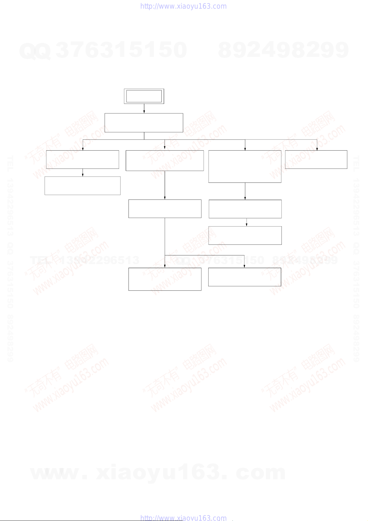
3-1. DISASSEMBLY FLOW
Q
•This set can be disassembled in the order shown below.
3-3. FL BOARD
3-4. JACK BOARD, SW BOARD
6
(Page 13)
(Page 13)
1
5
1
3
SET
3-2. CASE, FRONT PANEL ASSY
(Page 12)
3-9. DVD MECHANISM DECK
5
(CDM85-DVBU102)
(Page 16)
3-10. TRAY
(Page 16)
0
(DZ120/DZ120K),
I/O SCART BOARD
(DZ110/DZ111)
(Page 14)
4
2
9
8
3-5. I/O BOARD
3-6. MAIN BOARD
(Page 14)
3-7. DC FAN, TUNER UNIT
(Page 15)
8
9
3-8. POWER BOARD
2
9
(Page 15)
9
TEL 13942296513 QQ 376315150 892498299
TEL
13942296513
Q
Q
3-12. OPTICAL PICK-UP
(KHM-310CAA)
(Page 18)
5
1
3
6
7
3
3-11. BELT, MS-203 BOARD
(Page 17)
1
5
0
8
9
2
4
9
8
2
9
9
w
w
w
.
xia
o
y
u
1
6
3
.
c
o
m
11
HCD-DZ110/DZ111/DZ120/DZ120K
Note: Follow the disassembly procedure in the numerical order given.
Q
Q
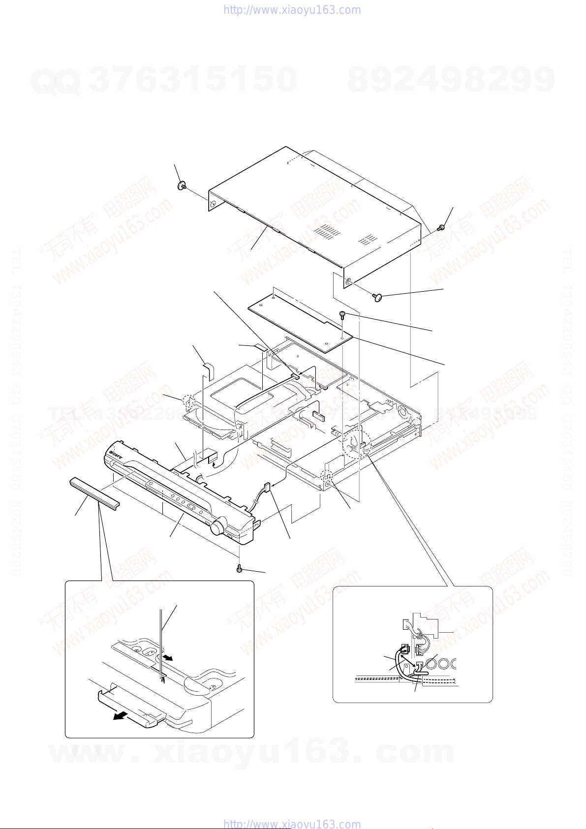
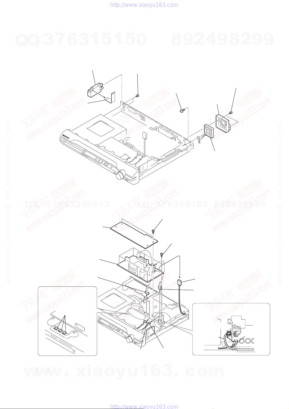
3-2. CASE, FRONT PANEL ASSY
TEL 13942296513 QQ 376315150 892498299
7
3
6
4
screw (CASE3 TP2)
9
connector (CN402) (DZ110/DZ111)
(CN312) (DZ120/DZ120K)
3
qs
1
sheet
5
8
sheet
1
7
5
case
0
8
9
2
4
9
6
five screws
(+BVTP 3 × 8)
5
(CASE3 TP2)
q;
two screws
(+BVTP 3 × 8)
qa
8
screw
cover (top)
2
9
9
TEL 13942296513 QQ 376315150 892498299
TEL
3
loading panel
qh
claw
13942296513
qd
w
ire (flat type)
23core (CN509)
qk
front panel assy
1
The lever is moved in the direction
of the arrow with the thin rod.
7
3
Q
Q
qf
connector (CN3001)
(EXCEPT DZ120K)
qg
three screws (+BV 3 × 6)
9
4
2
9
8
0
5
1
5
1
3
6
qj
claw
When re-assembling, leave 30 mm between
harnesses A and B for safety.
harnesses A
30mm
harnesses B
8
2
9
9
12
w
w
2
w
.
xia
o
y
u
1
6
3
.
c
clamp
o
m
HCD-DZ110/DZ111/DZ120/DZ120K
7
3
Q
TEL 13942296513 QQ 376315150 892498299
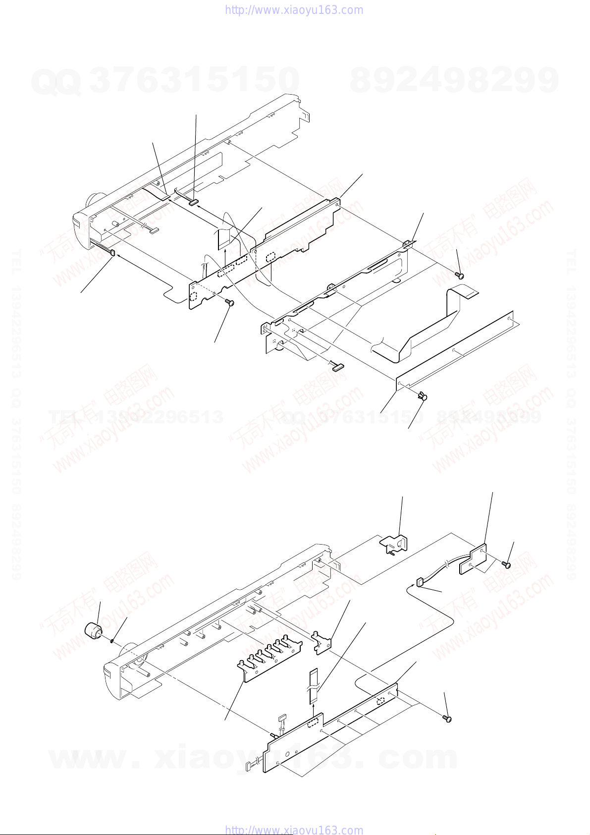
3-3. FL BOARD
Q
7
13core (CN805)
6
connector (CN803)
6
wire (flat type)
1
3
8
5
screw (+BVTP 2.6 × 8)
5
connector (CN811)
1
5
0
9
wire (flat type)
23core (CN801)
8
0
FL board
9
2
4
9
4
shield plate (fs)
2
8
3
five
screws (+BVTP 2.6 × 8)
9
9
TEL 13942296513 QQ 376315150 892498299
TEL
13942296513
3-4. JACK BOARD, SW BOARD
1
knob (vol)
2
nut
Q
Q
3
7
2
retainer K
5
1
3
6
7
button (play)
4
wire (flat type)
13core (CNP802)
0
5
1
1
three rivets
qa
button (power)
5
9
8
8
connector (CNP801)
JACK board
3
six
9
2
8
9
4
2
q;
SW board
9
two
(+BVTP 2.6)
screws (+BVTP 2.6)
9
screws
w
w
w
.
xia
6
button (play)
o
y
u
1
6
3
.
c
o
m
13
HCD-DZ110/DZ111/DZ120/DZ120K
7
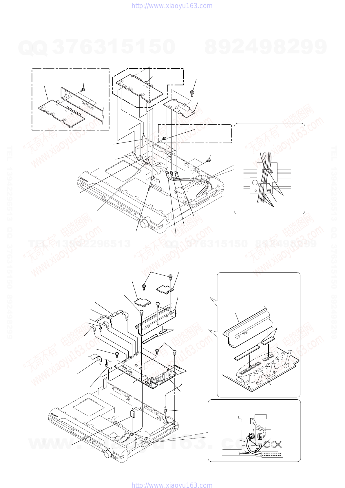
3-5. I/O BOARD (DZ120/DZ120K), I/O SCART BOARD (DZ110/DZ111)
Q
Q
(DZ120/DZ120K model) (DZ110/DZ111 model)
TEL 13942296513 QQ 376315150 892498299
3
wire (flat type)
13core (CN311)(DZ120/DZ120K)
21core (CN301)(DZ110/DZ111)
TEL
3-6. MAIN BOARD
3
7
I/O board
5
wire (flat type)
9core (CN101)(DZ120/DZ120K)
11core (CN101)(DZ110/DZ111)
4
wire (flat type)
13core (CN201)(DZ120/DZ120K)
13core (CN201)(DZ110/DZ111)
2
wire (flat type)
7core (CN202)(DZ120/DZ120K)
7core (CN304)(DZ110/DZ111)
13942296513
6
6
three
(+BVTP 3
screws
1
(CN302) (DZ110/DZ111)
(CN312) (DZ120/DZ120K)
1
3
×
8)
connector
5
1
5
7
board
0
I/O SCART
8
Q
Q
qs
two
(+BV 3 x 6)
qd
board
(DZ110/DZ111
model)
6
(+BVTP 3
qa
(+BVTP 3
q;
9
connector (CN302)
connector (CN303)
7
3
2
9
8
screws
SPEAKER
four
screws
×
8)
two
screws
×
8)
connector (CN301)
5
1
5
1
3
6
4
9
When assembling,
clamp the three harnesses with
a lead pin or a similar tool so
that they do not touch this screw.
three harnesses
2
9
8
0
8
lead pin
screw
4
2
9
8
9
2
9
9
TEL 13942296513 QQ 376315150 892498299
9
1
wire (flat type) 13core (CN1301)
2
wire (flat type) 7core (CN1302)
3
wire (flat type) 24core (CN1101)
4
connector (CN1201)
5
wire (flat type) 5core (CN1202)
qj
four screws (+BV 3 x6)
6
wire (flat type)
23core (CN509)
7
connector (CN515)
q;
two screws (+BV 3 x 8)
qa
HEATSINK A board
qd
two
screws
(+BVTP 3
×
10)
qs
HEATSINK B board
qg
heatsink (AMP)
qf
screw
(+BVTP 3
qh
two radiation
sheet
qk
four screws (+BV 3 x 6)
ql
two clamps
w;
MAIN board
9
connector
(CN3000)
When re-assembling, attaching the
two heat radiation sheets on the
IC MAIN board first, and then attach
the heat sink (AMP).
heatsink (AMP)
×
12)
When re-assembling, leave 30 mm between
harnesses A and B for safety.
30mm
radiation
sheets
IC on the
MAIN board
14
w
w
8
connector
w
(CN3002)
.
xia
o
y
u
1
6
3
harnesses A
.
c
o
harnesses B
m
HCD-DZ110/DZ111/DZ120/DZ120K
7
3
Q
TEL 13942296513 QQ 376315150 892498299
3-7. DC FAN, TUNER UNIT
Q
6
2
wire (flat type)
3
1
3
tuner unit
5
1
5
0
1
two screws (+BVTT 3 × 6)
6
(+BVTT 4
two
8
screws
9
×
8)
2
4
5
cover (fan)
9
4
(+BVTP 3
7
DC fan
8
two
2
screws
×
8)
9
9
TEL 13942296513 QQ 376315150 892498299
3-8. POWER BOARD
TEL
13942296513
When re-assembling, attach the
heat radiation sheets on the
chassis, and then install the
POWER board.
radiation sheets
4
cover (top)
9
POWER board
7
connector
(CN515)
Q
Q
3
6
7
3
3
two
screws
(+BVTP 3 × 8)
8
(+BV 3 × 8)
1
seven
2
8
9
4
2
9
8
0
5
1
5
screws
5
connector
(CN901)
6
connector
(CN3002)
When re-assembling, leave 30 mm between
harnesses A and B for safety.
30mm
harnesses A
harnesses B
9
9
w
w
w
.
xia
1
connector
(CN312) (DZ120/DZ120K)
(CN302) (DZ110/DZ111)
o
y
u
1
2
(CN3001)
(EXCEPT DZ120K)
6
3
connector
.
c
o
m
15
)
HCD-DZ110/DZ111/DZ120/DZ120K
7
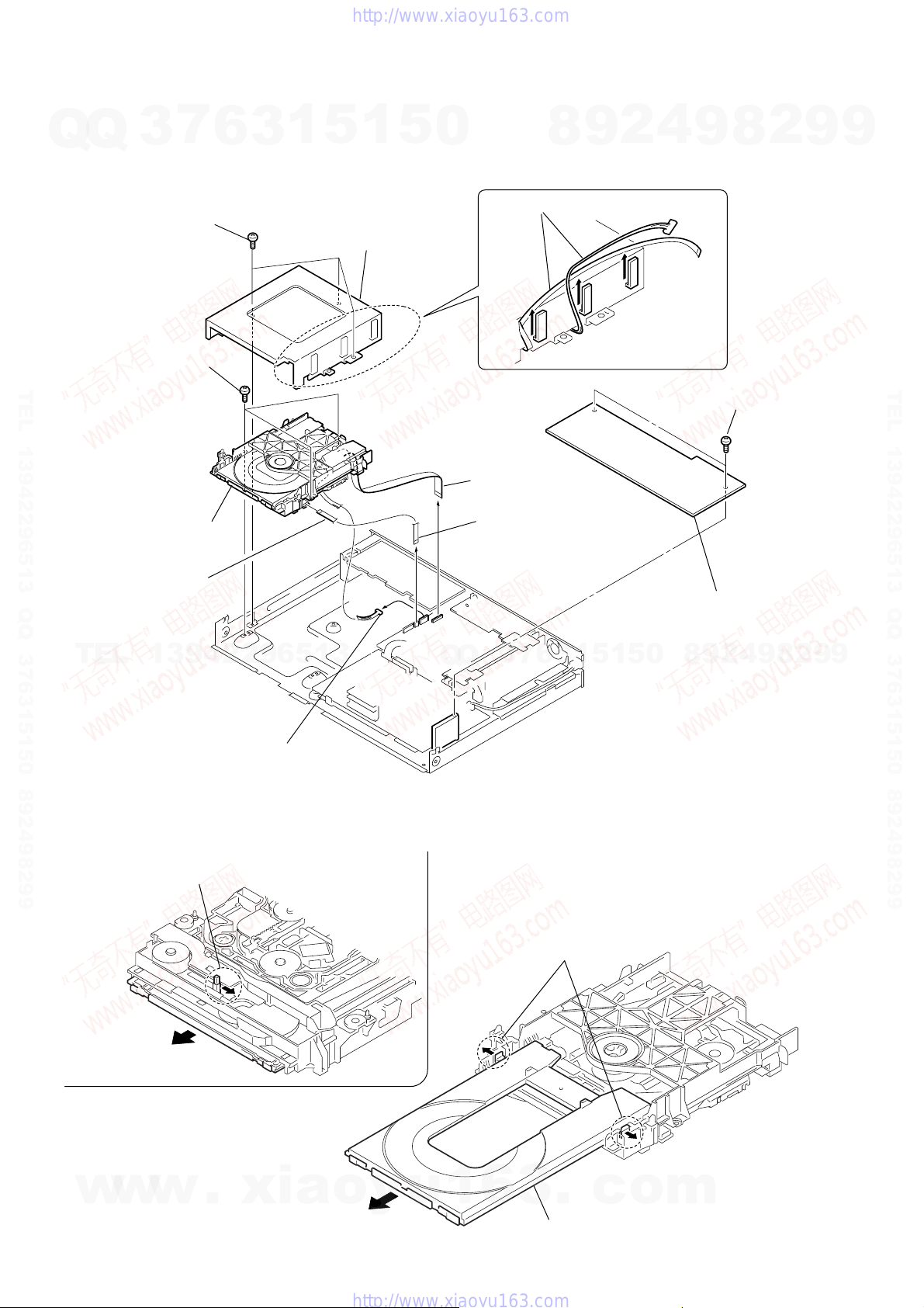
3-9. DVD MECHANISM DECK (CDM85-DVBU102)
Q
Q
7
three
9
three
TEL 13942296513 QQ 376315150 892498299
qa
DVD mechanism deck
(CDM85-DVBU102)
q;
3
screws (+BV 3 x 6)
screws (+BV 3 x 6)
wire (flat type) 5
6
core
3
1
5
1
8
cover (MD)
5
0
6
5
wire (flat type) 24
(CN1101)
4
wire (flat type) 5
(CN1202)
4
2
9
8
remove the wire and harness.
core
core
8
9
1
two
(+BVTP 3
2
cover (top)
2
screws
×
9
8
9
TEL 13942296513 QQ 376315150 892498299
TEL
3-10. TRAY
1
Move the chuck cam
in the direction of the arrow.
13942296513
3
connector (CN1201)
2
bottom side
Q
Q
3
7
3
3
6
two claws
1
5
1
5
0
8
9
2
4
9
8
2
9
9
16
w
w
w
.
xia
o
y
u
1
6
3
4
5
.
tray
c
o
m
HCD-DZ110/DZ111/DZ120/DZ120K
7
3
Q
TEL 13942296513 QQ 376315150 892498299
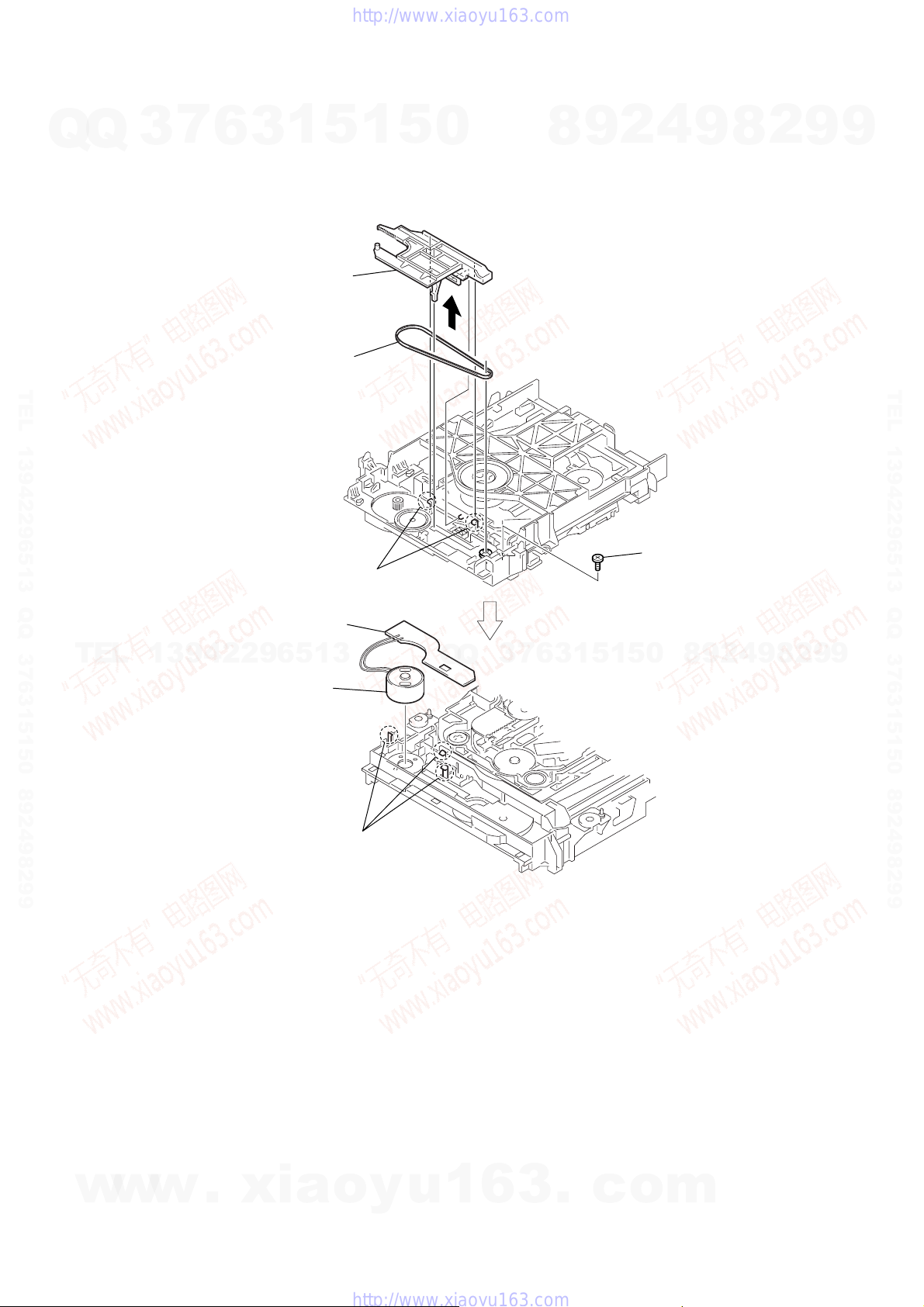
3-11. BELT, MS-203 BOARD
Q
6
3
1
2
chuck cam
3
5
belt
1
two claws
1
5
0
8
9
2
4
4
screw
(M 1.7 × 2.5)
9
8
2
9
9
TEL 13942296513 QQ 376315150 892498299
TEL
7
MS-203 board
13942296513
6
DC motor
5
three claws
Q
Q
3
7
6
3
1
5
1
5
0
8
9
2
4
9
8
2
9
9
w
w
w
.
xia
o
y
u
1
6
3
.
c
o
m
17
HCD-DZ110/DZ111/DZ120/DZ120K
7
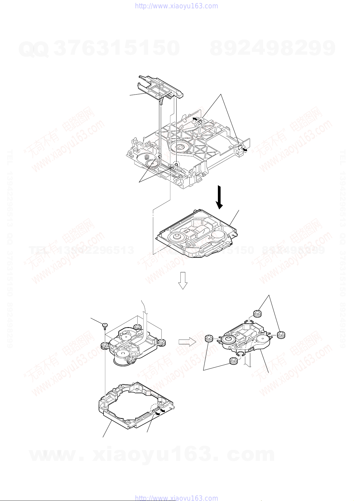
3-12. OPTICAL PICK-UP (KHM-310CAA)
Q
Q
TEL 13942296513 QQ 376315150 892498299
3
6
3
2
chuck cam
1
5
1
two claws
1
5
0
8
3
two claws
9
4
4
2
base unit
9
8
2
9
9
TEL 13942296513 QQ 376315150 892498299
TEL
13942296513
6
four insulator screws
Q
Q
7
3
9
two insulators
6
3
1
5
0
5
1
8
0
optical pick-up
(KHM-310CAA)
4
2
9
8
two insulators
9
8
2
9
9
18
w
w
w
7
.
xia
bu holder
5
two claws
o
y
u
1
6
3
.
c
o
m
HCD-DZ110/DZ111/DZ120/DZ120K
SECTION 4
TEST MODE
Ver. 1.4
7
Q
Q
TEL 13942296513 QQ 376315150 892498299
TEL
w
3
Note 1: Regarding the notification symbol “R”
Note 2: Incorrect operations may be performed if the test mode is
1. Cold Reset
• The cold reset clears all data including preset data stored in
the RAM to initial conditions. Execute this mode when
returning the set to the customers.
Procedure:
1. Press the ?/1 button to turn the power on.
2. Press three buttons x , A and ?/1 simultaneously.
3. When this button is operated, display as “COLD RESET” for
a while and all of the settings are reset.
2. Panel Test Mode
•This mode is used to check the software version, FL, LED
and KEY.
2-1. Display Test Mode
Procedure:
1. Press the ?/1 button to turn the power on.
2. Press three buttons X , . and A simultaneously.
3. When the display test mode is activated, all segments and LEDs
are turned on.
13942296513
4. To exit from this mode, press three buttons X , . and A
simultaneously.
2-2. V ersion T est Mode
Procedure:
1. When the display test mode is activated, press the . button
and the message “DSX1” (DZ110), “DSX1-” (DZ111),
“DSX1+” (DZ120), “DSX1K” (DZ120K) are displayed, the
version test mode is activated.
2. Whenever the . button is pressed, the display changes in
the following order.
“DSX1” (Model name) t “CE2*1” (Destination) t MC
TM T DSP T TA T ST T DVD T UI T SYS
*1: CE2 changes depending on destination.
3. Press the > button and the date of the software production
is displayed.
4. Press the > button again and the version is displayed.
5. To exit from this mode, press three buttons X , . and A
simultaneously.
2-3. Key Test Mode
Procedure:
1. When the display test mode is activated, press the H button,
to select the key test mode.
2. To enter the KEY test mode, the fluorescent indicator displays
“K0 V0”. Each time a button is pressed, “KEY” value
increases. However, once a button is pressed, it is no longer
taken into account. When all keys are pressed correctly, “K8
V0” is displayed.
3. When the VOLUME control is turned in the direction of (+),
“V0” is changed to “V1”, then ... “V9”.
w
w
When the V OLUME control is turned in the direction of (–),
“V0” is changed to “V9”, then ... “V1”.
4. To exit from this mode, press three buttons X , . and A
simultaneously.
6
Because the number of the operating buttons of this product
are limited, some operations require use of the operating
buttons of the remote commander, When a specific operation
requires use of the operating buttons of the remote
commander, “R” is added to the specific operating procedure
in this manual. Example MENU/NO “R” The MENU/NO
button of remote commander.
not entered properly.
In this case, press the ?/1 button to turn the po wer of f, and
retry to enter the test mode.
.
1
3
xia
5
o
1
y
5
u
0
Q
Q
1
3. Disc Tray Lock
The disc tray lock function for the antitheft of an demonstration
disc in the store is equipped.
Setting Procedure :
1. Press the ?/1 button to turn the set on.
2. Press the FUNCTION button to set DVD function.
3. Insert a disc.
4. Press the x button and the A button simultaneously for f ive
5. The message “LOCKED” is displayed and the tray is locked.
Releasing Procedure :
1. Press the x button and the A button simultaneously for f ive
2. The message “UNLOCKED” is displayed and the tray is
Note: When “LOCKED” is displayed, the slot lock is not released by
4. DVD Ship Mode
• Use this mode when returning the set to the customer after
Procedure:
1. Press the ?/1 button to turn the set on.
2. Press the FUNCTION button to set the function “DVD”.
3.
4. After a message “MECHA LOCK” is displayed on the
5. To exit from this mode, press the ?/1 button to turn the set on.
5. AM Step Change
•A step of AM channels can be changed over between 9 kHz
7
3
Procedure:
1. Press the ?/1 button to turn the set ON.
2. Select the function “TUNER”, and press FUNCTION button
3. Press the ?/1 button to turn the set OFF.
4. Press two buttons > and ?/1 simultaneously, and the
6. V olume Test Mode
Procedure:
1. Press the ?/1 button to turn the power on.
2. Press three buttons . , H and > simultaneously.
3. The message “VOLUME MAX” is displayed, when the
4. To exit from this mode, press the ?/1 button to turn the set off.
7. Product Out
This mode moves the optical pick-up to the position durable to
vibration and clears all data including preset data stored in the RAM
to initial conditions. Use this mode when returning the set to the
customer after repair.
Procedure:
1. Press the ?/1 button to turn the power on.
2. Press the FUNCTION button to set the function “DVD”.
3.
4. After the “STANDBY” blinking display finishes, the message
6
3
4
2
9
8
seconds.
seconds again.
unlocked.
turning power on/off with the ?/1 button.
repair.
Remove all discs, and then press two buttons x and
simultaneously.
fluorescent indicator tube, pull out the AC plug.
0
5
1
5
1
3
6
and 10 kHz.
to select the BAND “AM”.
display of fluorescent indicator tube changes to “AM 9 k
STEP” or “AM 10 k STEP”, and thus the channel step is
changed over.
VOLUME control is turned in the dirction of (+).
The message “VOLUME MIN” is displayed, when the
VOLUME control is turned in the dirction of (–).
Remove all discs, and then
?/1 simultaneously.
.
c
“MECHA LOCK” is displayed on the fluorescent indicator
tube disconnect the A C po wer plug, then the ship mode is set.
o
9
2
9
8
press three buttons > , A and
m
8
4
2
9
8
9
2
9
9
.
9
TEL 13942296513 QQ 376315150 892498299
19
HCD-DZ110/DZ111/DZ120/DZ120K
Ver. 1.4
7
Q
Q
DVD SECTION
8-1. GENERAL DESCRIPTION
The IOP measurement allows you to make diagnosis and adjustment
simply by using the remote commander and monitor TV. The
instructions, diagnosis results, etc. are given on the on-screen display
(OSD).
Be sure to execute the IOP measurement when a BU (Base Unit) is
replaced.
8-2. HOW TO ENTER TEST MODE
While pressing the x and A buttons simultaneously, turn
VOLUME + with the DVD player in power on.
The T est Mode starts, then the menu shown belo w will be displayed
TEL 13942296513 QQ 376315150 892498299
on the TV screen.
* The display of the “Model Name” of the “Remocon Diagnosis
Menu” change with the model and the destination. Refer to below
on the model name.
DZ110 : DSX1
DZ111 : DSX1–
DZ120 : DSX1+
DZ120K : DSX1K
TEL
*1: Changes depending on destination
The menu above is the Remocon Diagnosis Menu screen which
consists of five main functions. At the bottom of the menu screen, the
model name and IF-con version. To exit from the Test Mode, press
the power button on the remote commander.
8-3. EXECUTING IOP MEASUREMENT
In order to execute IOP measurement, the following standard
procedures must be followed.
(1) In power on, while pressing the x and A buttons
simultaneously, turn VOLUME + .
*1: Changes depending on destination
3
Remocon Diagnosis Menu
0. External Chip Check
1. Servo Parameter Check
2. Drive Manual Operation
3. Emergency History Check
4. Version Information
Model Name
IF-con : V
Syscon : Ver.
0. External Chip Check
1. Servo Parameter Check
2. Drive Manual Operation
3. Emergency History Check
4. Version information
Model Name
IF-con : Ver. XX.XX (XXXX)
Syscon : Ver. X.XXX
13942296513
Remocon Diagnosis Menu
6
: DSX1_ XX
er. XX.XX (XXXX)
: DSX1_ XX
*
X.XXX
*
1
1
3
1
5
1
5
(2) Select “2. Drive Manual Operation” by pressing the 2 “R”
0
button on the remote commander. The screen will appear as
shown.
1. Servo Control
2. Track/Layer Jump
3. Manual Adjustment
4. Tray Aging Mode
5. MIRR time adjust
0. Return to top Menu
(3) Select “3. Manual Adjustment” by pressing the 3 “R” b utton
on the remote commander. The screen will appear as shown.
1. Track Balance Adjust:
2. Track Gain Adjust:
3. Focus Balance Adjust:
4. Focus Gain Adjust:
5. Eq boost Adjust:
6. Iop:
7. TRV. Level:
8. S curve(FE) Level:
9. RFL(PI) Level:
0. MIRR Time:
o O Change Value
[RETURN] Return to previous menu
(4) Select “6.IOP” by pressing the 6 “R” button on the remote
commander.
7
3
Q
Q
(5) Wait until a hexadecimal number appear.
1. Track Balance Adjust:
2. Track Gain Adjust:
3. Focus Balance Adjust:
4. Focus Gain Adjust:
5. Eq Boost Adjust:
6. Iop. 5B:
7. TRV. Level:
8. S curve(FE) Level:
9. RFL(PI) Level:
0. MIRR Time:
Change Value
[0] Return to previous menu
(6) Convert each data from hexadecimal to decimal using
conversion table.
(7) Please find the label on the rear of the BU (Base Unit).
The default IOP value is written in the label.
(8) Subtract between these two values.
(9) If the remainder is smaller than 93 (decimal), then it is OK.
Ho wever if the v alue is higher than 93, then the BU is defecti ve
and need to be change.
2
9
8
Drive Manual Operation
Manual Adjust
5
1
5
1
3
6
Manual Adjust
4
0
9
8
9
8
2
4
2
9
8
9
2
9
9
TEL 13942296513 QQ 376315150 892498299
9
20
w
w
w
.
xia
(10) Press the RETURN “R” button to return back to previous
menu.
o
y
u
(11) Press the 0 “R” button to return to Top Menu and power
1
6
3
off the DVD Player.
.
c
o
m
HCD-DZ110/DZ111/DZ120/DZ120K
Ver. 1.4
Q
TEL 13942296513 QQ 376315150 892498299
8-4. EMERGENCY HISTORY
Q
To check the emergency history, please follow the following
procedure.
(1) From the Top Menu of Remocon Diagnosis Menu, select “3.
(2) You can check the total time when the laser is turned on during
(3) You can check the error code of latest 10 emergency history
TEL
• Error Code
7
3
Emergency History Check” by pressing the 3 “R” button on
the remote commander. The following screen appears on the
on-screen display.
Laser Hours CD 999h 59min
1. 01 05 04 04
00 00 00 00 00 00 23 45
2. 02 02 01 01 00 A9 4B 00
00 00 00 00 00 00 23 45
Next Next Page Prev Prev Page
O Return to Top Menu
playback of DVD and CD from the abov e menu. The maximum
time, which can be displayed are 999h 59min.
from the above menu. To view the previous or next page of
emergency history , press . “R” or > “R” on the remote
commander. The error code consists of the following three
blocks. The first block indicates the error code. The second
block indicates the parameter and the third block indicates the
time of error code as shown below.
6
Emg.History Check
13942296513
Emg.History Check
Laser Hours CD 999h 59min
*1*
2
1. 01 05 04 04
00 00 00 00 00 00 23 45
2. 02 02 01 01 00 A9 4B 00
00 00 00 00 00 00 23 45
Next Next Page Prev Prev Page
O Return to Top Menu
*1 : Error Code
*2 : Parameter of error code
*3 : Time of error code
1
5
3
DVD 999h 59min
00 92 46 00
DVD 999h 59min
00 92 46 00
1
*
5
0
8-4-1. Clear the Laser Hour
Press DISPLAY “R” button and then press CLEAR “R” button.
The data for both CD and DVD data are reset.
7
3
Q
Q
Laser Hours CD 0h 0min
1. 01 05 04 04
2. 02 02 01 01 00 A9 4B 00
3
Next Next Page Prev Prev Page
O Return to Top Menu
8-4-2. Clear the Emergency History
Press TOP MENU “R” button and then press CLEAR “R” button.
The error code for all emergency history would be reset.
4
The meaning of error code is as below:
8
01: Communication error (No reply from syscon)
02: Syscon hung up
03: Power OFF request when syscon hung up
19: Thermal shutdown
24: MoveSledHome error
25: Mechanical move error (5 Changer)
26: Mechanical move stack error
30: DC motor adjustment error
31: DPD offset adjustment error
32: TE balance adjustment error
33: TE sensor adjustment error
34: TE loop gain adjustment error
35: FE loop gain adjustment error
36: Bad jitter after adjustment
40: Focus NG
42: Focus layer jump NG
52: Open kick spindle error
51: Spindle stop error
60: Focus on error
61: Seek fail error
62: Read Q data/ID error
70: Lead in data read fail
71: TOC read time out (CD)
80: Can’t buffering
81: Unknown media type
3
6
00 00 00 00 00 00 23 45
00 00 00 00 00 00 23 45
2
9
0
5
1
5
1
Emg.History Check
DVD 0h 0min
Emg.History Check
9
2
9
8
00 92 46 00
8
4
2
9
8
2
9
9
9
TEL 13942296513 QQ 376315150 892498299
9
w
w
w
.
xia
8-4-3. Clear the Initialize Setup Data
Press MENU “R” button and then press CLEAR “R” button on
the remote commander.
o
y
u
1
6
3
Laser Hours CD 999h 59min
1. 00 00 00 00
00 00 00 00 00 00 00 00
2. 00 00 00 00 00 00 00 00
00 00 00 00 00 00 00 00
Next Next Page Prev Prev Page
O Return to Top Menu
.
DVD 999h 59min
00 00 00 00
c
o
m
21
HCD-DZ110/DZ111/DZ120/DZ120K
Ver. 1.4
8-4-4. Return to the Top Menu of Remocon Diagnosis
Q
Q
Menu
Press 0 “R” button on the remote commander.
• Check Version Information
To check the version information, please follow the following
procedure.
(1) From the Top Menu of Remocon Diagnosis Menu, select “4.
Version Information” by pressing the 4 “R” button on the
remote commander. The following screen appears on the onscreen display.
TEL 13942296513 QQ 376315150 892498299
Firm (Main) : Ver. xxxxx
Firm (Sub) : xxxxx
RISC : xxxxx
8032 : xxxxx
Audio DSP : xxxxx
Servo DSP : xxxxx
O Return to Top Menu
To return to the T op Menu of Remocon Diagnosis Menu, press
0 “R” on the remote commander.
7
3
Version information
6
3
1
5
1
5
0
8
9
2
4
9
8
2
9
9
TEL 13942296513 QQ 376315150 892498299
TEL
13942296513
Q
Q
3
7
6
3
1
5
1
5
0
8
9
2
4
9
8
2
9
9
22
w
w
w
.
xia
o
y
u
1
6
3
.
c
o
m
)
HCD-DZ110/DZ111/DZ120/DZ120K
SECTION 5
ELECTRICAL ADJUSTMENT
7
Q
Q
TEL 13942296513 QQ 376315150 892498299
3
DVD SECTION
When the base unit is replaced, perform the adjustment and the
measurement as shown below in this order.
EXECUTING IOP MEASUREMENT (See page 20)
[TEST DISC LIST]
Be sure to use the DVD disc that matches the signal standards of
your region.
• CD YEDS-18 (Part No.: 3-702-101-01)
• DVD SL (Single Layer)
NTSC : HLX-503 (Part No.: J-6090-069-A)
PAL : HLX-506 (Part No.: J-6090-077-A)
• DVD DL (Dual Layer)
NTSC : HLX-501 (Part No.: J-6090-071-A)
PAL : HLX-507 (Part No.: J-6090-078-A)
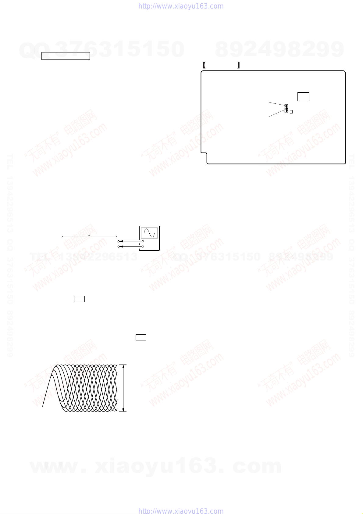
[RF Level Check]
Connection:
CN1105 pin 6 (RFMON)
CN1105 pin 3 (GND)
6
PATD-012 (Part No.: 4-225-203-01)
HLX-504 (Part No.: J-6090-088-A)
HLX-505 (Part No.: J-6090-089-A)
MAIN board
3
1
5
oscilloscope
1
+
–
5
0
Checking Location: MAIN board (Side A)
MAIN BOARD
4
2
9
8
(SIDE A)
CN1105 Pin 6 (RFMON)
CN1105 Pin 3 (GND)
9
CN1105
8
IC1103
2
IC501
9
9
TEL 13942296513 QQ 376315150 892498299
TEL
13942296513
Procedure:
1. Connect an oscilloscope to CN1105 pin 6 (RFMON) and
CN1105 pin 3 (GND) on the MAIN board.
2. Turn the power on.
3. Insert the CD test disc (refer to the TEST DISC LIST), and
press the H button to play the disc back.
4. Confirm that oscilloscope waveform is clear and check RF
signal level is correct or not.
Note: A clear RF signal waveform means that the shape “◊” can be
clearly distinguished at the center of the waveform.
5. Eject the CD disc, and insert the DVD SL test disk (refer to
the TEST DISC LIST), and press the H button to play the
disc back.
RF signal waveform
VOLT/DIV: 200 mV
TIME/DIV: 500 ns
level: 0.57 to 1.1 Vp-p (CD)
0.58 to 1.23 Vp-p (DVD
Q
Q
3
7
6
3
1
5
1
5
0
8
9
2
4
9
8
2
9
9
w
w
w
.
xia
o
y
u
1
6
3
.
c
o
m
23
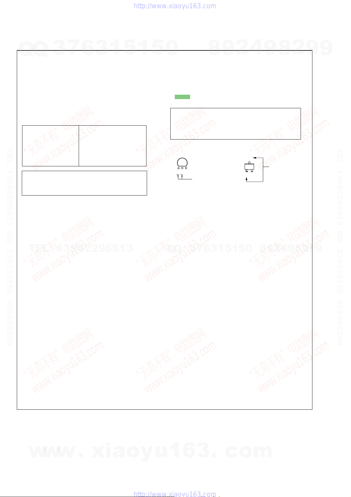
C
B
These are omitted.
E
Q
HCD-DZ110/DZ111/DZ120/DZ120K
Ver. 1.3
SECTION 6
DIAGRAMS
7
Q
Q
THIS NOTE IS COMMON FOR PRINTED WIRING BOARDS AND SCHEMATIC DIAGRAMS.
(In addition to this, the necessary note is printed in each block.)
For Schematic Diagrams.
Note:
• All capacitors are in µF unless otherwise noted. (p: pF)
50 WV or less are not indicated except f or electrolytics and
tantalums.
• All resistors are in Ω and 1/
specified.
• f : internal component.
• C : panel designation.
Note:
The components identified by mark 0 or dot-
TEL 13942296513 QQ 376315150 892498299
ted line with mark 0 are
critical for safety.
Replace only with part
number specified.
✩ New part of EEP ROM (IC1103) on the MAIN board
cannot be used. Therefore, if the mounted MAIN board
(A-1144-739-A, etc.) is replaced, exchange new EEP
ROM (IC1103) with that used before the replacement.
• A : B+ Line.
•Voltages and wav ef orms are dc with respect to ground under no-signal (detuned) conditions.
•Voltages and waveforms are dc with respect to ground in
service mode.
•Waveforms are taken with a oscilloscope.
Voltage v ariations ma y be noted due to normal production
tolerances.
no mark : DVD STOP
TEL
* : Impossible to measure
•Voltages are taken with VOM (Input impedance 10 MΩ).
• Circled numbers refer to waveforms.
• Signal path.
F : AUDIO
J : CD PLAY
c : DVD PLAY
I : SACD PLAY
d : TUNER
L : VIDEO
E : Y
a : CHROMA
r : COMPONENT VIDEO
q : R, G, B
f : AUDIO IN
•Abbreviation
AUS: Australian Model
AR : Argentina model
CND : Canadian Model
E3 : 240V AC area in E model
E12 : 220-240V AC area in E model
E32 : 110-240V AC area in E model
EA : Saudi Arabia model
KR : Korean model
MX : Mexican model
RU : Russian model
SP : Singapore model
TW : Taiwan model
3
13942296513
6
4
W or less unless otherwise
Note:
Les composants identifiés
par une marque 0 sont critiques pour la sécurité.
Ne les remplacer que par une
piéce portant le numéro
spécifié.
3
1
5
1
5
0
For Printed Wiring Boards.
Note:
• X : parts extracted from the component side.
• a : Through hole.
• : Pattern from the side which enables seeing.
(The other layers' patterns are not indicated.)
Caution:
Pattern face side: Parts on the pattern face side seen from
(SIDE B) the pattern face are indicated.
Parts face side: Parts on the parts face side seen from
(SIDE A) the parts face are indicated.
• Indication of transistor.
CEB
These are omitted
6
7
3
Q
Q
8
3
9
1
5
2
1
5
4
0
9
8
9
8
2
4
2
9
8
9
2
9
9
TEL 13942296513 QQ 376315150 892498299
9
w
w
w
24
.
xia
o
y
u
1
6
3
.
c
o
m
HCD-DZ110/DZ111/DZ120/DZ120K
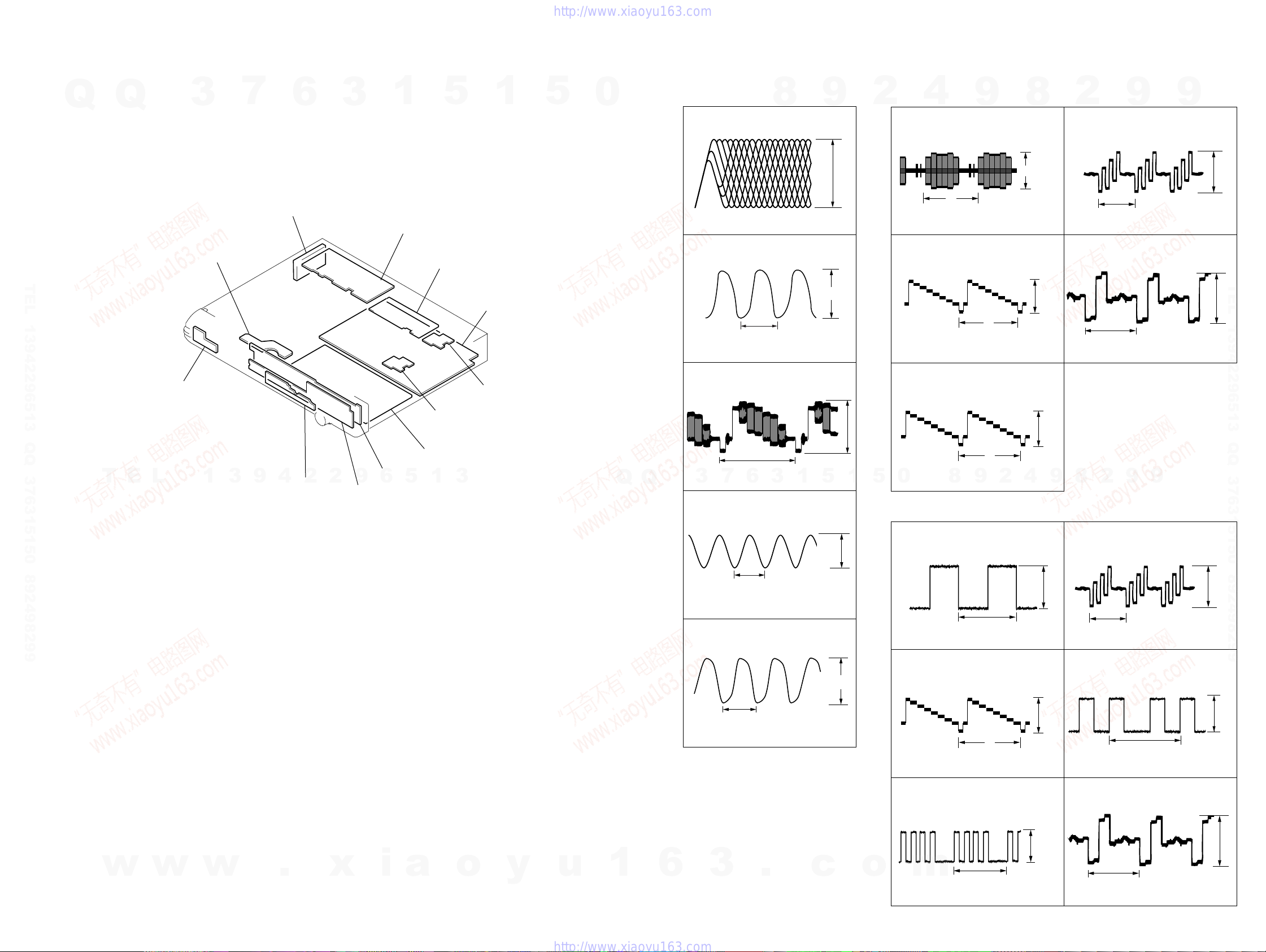
• Circuit Boards Location
Q
TEL 13942296513 QQ 376315150 892498299
Q
SW board
3
MS-203 board
7
TUNER UNIT
6
3
1
I/O board (DZ120/DZ120K)
I/O SCART board (DZ110/DZ111)
5
SPEAKER board
HEATSINK B board
1
MAIN board
HEATSINK A board
5
0
•Waveforms
– MAIN Board –
1
IC1101 6 (DVDRFIP)
200 mV/DIV, 100 ns/DIV
2
IC1101 <xx. (XTALI)
37 ns
1 V/DIV, 10 ns/DIV
3
IC1101 <z., (YUV3)
8
9
900 mVp-p
1.7 Vp-p
1.5 Vp-p
– I/O Board (DZ120/DZ120K) –
2
4
6
IC201 wh (COUT)
H
1 V/DIV, 20 µs/DIV
7
IC201 wa (YOUT)
1 V/DIV, 20 µs/DIV
8
IC201 w; (CYOUT)
9
H
8
2.0 Vp-p
2.2 Vp-p
2.2 Vp-p
2
9
IC201 qk (CbOUT)
500 mV/DIV, 20
0
IC201 qh (CrOUT)
500 mV/DIV, 20 µs/DIV
9
H
µ
s/DIV
H
9
1.6 Vp-p
TEL 13942296513 QQ 376315150 892498299
1.6 Vp-p
T
E
L
1
3
9
4
2
DDCON board
2
FL board
9
6
JACK board
POWER board
5
1
3
Q
Q
H
6
7
3
500 mV/DIV, 20 µs/DIV
4
IC501 qg (XIN)
200 ns
1 V/DIV, 100 ns/DIV
5
IC3010 rk (XFSOIN)
20.3 ns
1 V/DIV, 10 ns/DIV
3
1
5
2.7 Vp-p
5.5 Vp-p
1
H
2
9
0
5
1 V/DIV, 20
– I/O SCART Board (DZ110/DZ111) –
6
500 mV/DIV, 20 µs/DIV
7
1 V/DIV, 20 µs/DIV
8
µ
s/DIV
IC230 wf (CYOUT)
H
IC201 wf (CYOUT)
H
1.7 Vp-p
2.2 Vp-p
4
2
8
9
9
IC201 wa (CbOUT)
500 mV/DIV, 20
0
IC230 qk (CrOUT)
500 mV/DIV, 20 µs/DIV
9
H
µ
9
1.6 Vp-p
s/DIV
1.7 Vp-p
H
w
HCD-DZ110/DZ111/DZ120/DZ120K
w
w
.
x
i
a
o
y
u
1
6
3
2525
.
c
o
8
IC230 wa (CbOUT)
m
500 mV/DIV, 20 µs/DIV
qa
IC201 qk (CrOUT)
1.7 Vp-p
H
500 mV/DIV, 20 µs/DIV
H
1.6 Vp-p
HCD-DZ110/DZ111/DZ120/DZ120K
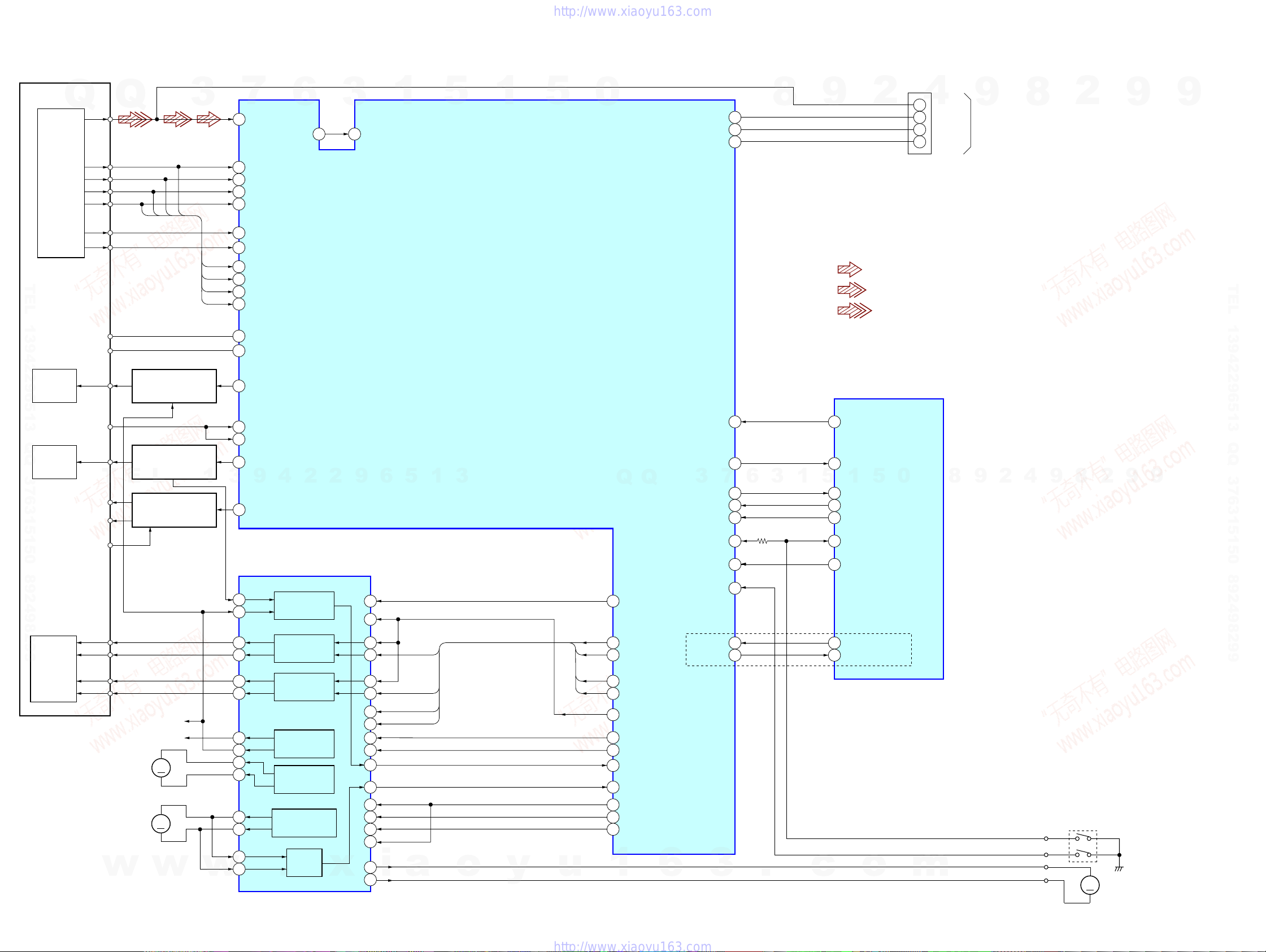
6-1. BLOCK DIAGRAM – RF SECTION –
Q
DETECTOR
TEL 13942296513 QQ 376315150 892498299
OPTICAL PICK-UP
BLOCK
(KHM-310CAA)
LASER
DIODE
(FOR CD)
RF
VC
LIMIT
CD LD
A
B
C
D
F
E
Q
C
D
AUTOMATIC POWER
CONTROL (FOR CD)
Q1102 (1/2)
3
B
A
A
B
D
C
7
6
2
3
4
5
19
18
8
9
10
11
29
176
23
DVDRFIP
DVDA
DVDB
DVDC
DVDD
TPI
TNI
NA
NB
MD
MC
V2O
LI M SW
LD01
6
OSP
3
252 253
OSN
1
5
IC1101 (1/3)
CD/DVD RF AMP,
FOCUS/TRACKING ERROR AMP
DVD SYSTEM PROCESSOR
DIGITAL SERVO PROCESSOR
1
5
0
V2REFO
RXD
TXD
28
106
107
8
9
• Signal Path
CONTROLLER
2
: CD PLAY
: DVD PLAY
: SACD PLAY
IC501 (1/4)
SYSTEM
CN1105
4
6
5
2
1
RFMON
V2REFO
RXD
TXD
9
TO DIAG JIG
8
2
9
9
TEL 13942296513 QQ 376315150 892498299
LASER
DIODE
(FOR DVD)
2AXIS
DEVICE
FOCUS/
TRACKING
COIL
PD
DVD LD
T
E
VR650
VR780
MSW
FCS+
FCS–
TRK+
TRK–
(SLED MOTOR)
(SPINDLE MOTOR)
w
Q1102 (2/2)
AUTOMATIC POWER
CONTROL (FOR DVD)
L
Q1101, Q1103
VOLUME CONTROL
+3.6V
+2.5V
MM
MM
w
1
SL–
SL+
SP+
SP–
w
20
MD12
MD11
21
LD02
22
3
9
4
2
2
MSW
50
FOCUS/TRACKING COIL DRIVER,
SPINDLE, SLED MOTOR DRIVER
IOP
42
41
36 48
37 1
35 3
34 4
32
31
30
29
27
28
47
46
IC1201
BUFFER
FOCUS COIL
DRIVE
TRACKING COIL
DRIVE
SLED MOTOR
DRIVE
SLED MOTOR
DRIVE
SPINDLE MOTOR
DRIVE
BUFFER
.
x
9
6
.
SYSRST
SCO
3
SCD
SID
1
5
c
43
MTK_RST
33
DVD_SCO
1
32
DVD_SOD
31
DVD_SID
37
DVD_XIFCS
27
CDM_OPEN_SW
34
DVD_XIFBUSY
35
MIC_DET
36
KARAOKE_MODE
o
5
0
DZ120K
m
8
9
4
2
OCSW1
OCSW/CKSW
LDM+
LDM-
2
8
9
S001
(CHUCK/TRAY DETECT)
(LOADING MOTOR)
MM
9
9
110
PRST
99
IFCK
6
5
1
3
15
43
10
13
16
17
40
45
19
20
22
21
25
22
i
24
VREFO
FOO
TRO
FMO
DMO
a
o
y
FMO
FOO
DMO
TRO
u
Q
39
TROPENPWN
38
FMO
42
FOO
37
DND
41
TRO
V REFO
30
174
FWD
178
REV
40
IOPMON
47
SPFG
211
MUTE123
210
MUTE
170
TSDM
1
Q
6
3
IFSDO
IFSDI
XIFCS
OCSW
IFBSY
CKSW
MIC
KRMOD
3
7
98
101
100
177
105
179
205
207
HCD-DZ110/DZ111/DZ120/DZ120K
2626
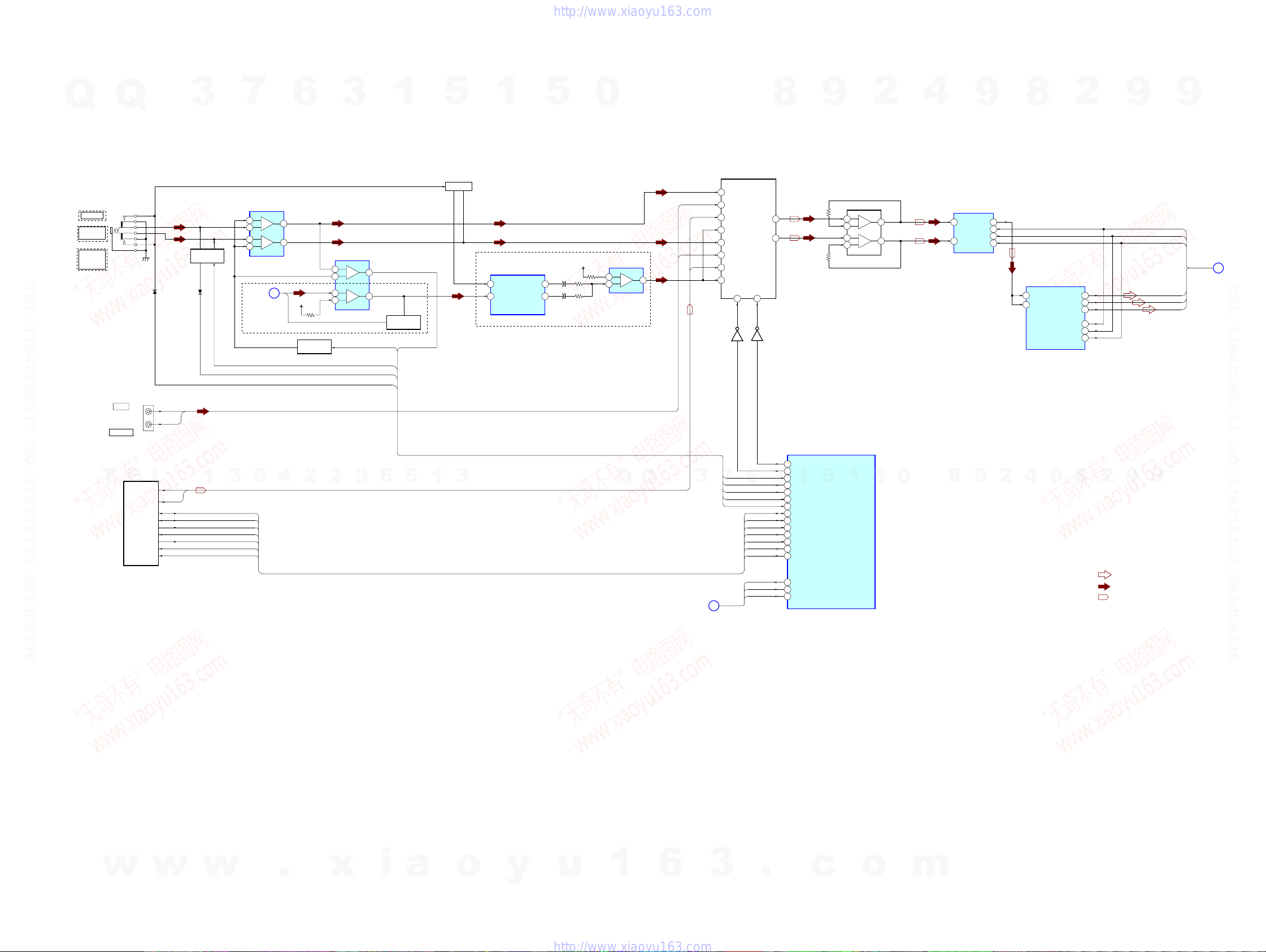
6-2. BLOCK DIAGRAM – AMP SECTION –
HCD-DZ110/DZ111/DZ120/DZ120K
3
RDS_DATA
RDS_CLK
TUNED
PLL CK
PLL DO
PLL CE
PLL DI
7
6
5
3
2
AUDIO
SECTION
(Page 28)
DZ120K
9
IC401
AMP
–
+
+
6
7
1
–
C
+9V
Q474,475
GAIN CONT
4
2
MIC2
3
IC402
AMP
5
+
–
6
3
+
–
2
GAIN CONT ACAL
MO/ST DET
PLUG DET1
2
9
Q
DZ110/DZ111
AUDIO IN
AUDIO IN/
A.CAL MIC
AUDIO IN/
MIC1/
A.CAL MIC
Q
J401
DZ120
DZ120K
3
Q470-473,476
MO/ST DETECT
TEL 13942296513 QQ 376315150 892498299
D433 D470
J203 (DZ110/DZ111)
LINE
J200 (DZ120/DZ120K)
VIDEO/SAT
T
E
SECTION
TUNER
L
L
R
L-CH
R-CH
1
7
1
PLUG DET2
DC CONT
6
1
Q477-478
PLUG DET
Q360,361,362 (DZ120/DZ120K)
Q300,310,320 (DZ110/DZ111)
5
1
5
MUTING
3
1
1
VIN2
VIN2
8
IC357
BUFFER
VOUT1
VOUT2
5
2
7
IC1101 (2/3)
9
SDATA0
SDATA1
SDATA2
ALRCK
ABCK
ACLK
2
217
218
219
213
214
215
8
2
• Signal Path
: AUDIO
: AUDIO IN
: TUNER
9
9
AMP LRCKO
AMP BCKO
AMP MCKO
9
AMP D1
AMP D2
AMP D3
9
AUDIO
SECTION
A
(Page 28)
TEL 13942296513 QQ 376315150 892498299
0
4
LIN
RIN
A/D CONVERTER
1
LIN
RIN
2
8
9
IC2200
9
DOUT
LRCK
SCKI
BCK
8
12
10
11
15
DVD SYSTEM PROCESSOR
209
SPDATA
DWIDE
224
4
2
0
IC352 (DZ120/DZ120K)
IC350 (DZ110/DZ111)
AUDIO INPUT SELECTOR
11
Q353
(DZ120/DZ120K)
Q395
(DZ110/DZ111)
3
B
15
14
12
4
2
5
1
7
X3
X2
X1
X0
Y3
Y2
Y1
Y0
A
10B9
A SEL1
ACAL
GAIN CONT
MO/ST DET
PLUG DET1
L
+5V
+
+
IC356
COMPARATOR
3
+
–
2
Q
1
DZ120K
Q
R
VIDEO
SECTION
(Page 29)
A SEL0
6
RDS_DATA
RDS_CLK
TUNED
PLL CK
PLL DO
PLL CE
PLL DI
V_SEL0
V_SEL1
DVD_SEL
8
13
X
3
Y
Q354 (DZ120/DZ120K)
Q396 (DZ110/DZ111)
82
83
91
3
26
28
90
100
76
75
69
70
71
72
73
71
72
81
SYSTEM CONTROL
A-SEL0
A-SEL1
ACAL MIC LEVEL
1
MIC GAIN
DC CONT
MONO/ST DET
MIC/A CALSW
RDS_DATA
RDS_CLK
TUNED
ST_CLK
ST_DO
ST_CE
ST_DI
V_SEL0
V_SEL1
TVSEL/V_SEL3
9
IC501 (2/4)
5
2
IC353 (DZ120/DZ120K)
IC360 (DZ110/DZ111)
AMP
3
+
–
2
5
+
–
6
5
1
1
7
w
w
w
HCD-DZ110/DZ111/DZ120/DZ120K
.
x
i
a
o
y
u
1
6
3
2727
.
c
o
m
 Loading...