

Sony HCD-BX9, HCD-DX9 Service Manual
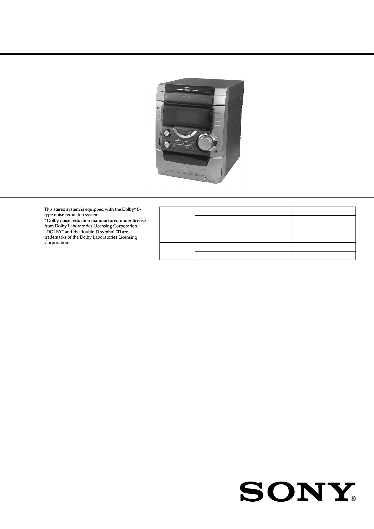
HCD-BX9/DX9
SERVICE MANUAL
Ver 1.2 2001.08
HCD-BX9/DX9 is the tuner, deck, CD and
amplifier section in MHC-BX9/DX9.
Photo: HCD-DX9
CD
SECTION
TAPE DECK
SECTION
Model Name Using Similar Mechanism HCD-BX7/DX7/DX7J
CD Mechanism Type CDM58-K2BD38
Base Unit Type BU-K2BD38
Optical Pick-up Type KSM-213DAP/ZNP
Model Name Using Similar Mechanism HCD-BX7/DX7/DX7J
Tape Transport Mechanism Type TCM-230MWR11
AEP Model
UK Model
HCD-BX9
E Model
Australian Model
HCD-DX9
Amplifier section
European model:
DIN power output (rated)
130 + 130 W
(6 Ω at 1 kHz, DIN)
Continuous RMS power output (reference)
170 + 170 W
(6 Ω at 1 kHz, 10% THD)
Other models:
The following measured at AC 120, 220, 240 V
50/60 Hz
DIN power output (rated)
220 + 220 W
(4 Ω at 1 kHz, DIN)
Continuous RMS power output (reference)
300 + 300 W
(4 Ω at 1 kHz, 10% THD)
Inputs
MD/VIDEO (AUDIO) IN:
(phone jacks)
voltage 450 mV/250 mV,
impedance 47 kΩ
MIC:
(phone jack)
sensitivity 1 mV,
impedance 10 kΩ
Outputs
PHONES:
(stereo mini jack)
accepts headphones of 8 Ω or more
FRONT SPEAKER:
HCD-BX9:
accepts impedance of 6 to 16 Ω
HCD-DX9:
accepts impedance of 4 to 16 Ω
9-929-239-13
2001H0200-1
© 2001.8
Sony Corporation
Home Audio Company
Shinagawa Tec Service Manual Production Group
SPECIFICATIONS
CD player section
System
Compact disc and digital audio system
Laser
Semiconductor laser (λ=780 nm)
Emission duration: continuous
Laser output
Max. 44.6 µW*
*This output is the value measured at a
distance of 200 mm from the objective
lens surface on the Optical Pick-up Block
with 7 mm aperture.
Frequency response
2 Hz – 20 kHz (±0.5 dB)
Wavelength
780 – 790 nm
Signal-to-noise ratio
More than 90 dB
Dynamic range
More than 90 dB
CD OPTICAL DIGITAL OUT
(Square optical connector jack, rear panel)
Wavelength 660 nm
Output Level –18 dBm
Tape player section
Recording system
4-track 2-channel stereo
Frequency response (DOLBY NR OFF)
40 – 13,000 Hz (±3 dB),
using Sony TYPE I cassette
COMPACT DISC DECK RECEIVER
Tuner section
FM stereo, FM/AM superheterodyne tuner
FM tuner section
Tuning range
87.5 – 108.0 MHz
Antenna
FM lead antenna
Antenna terminals
75 Ω, unbalanced
Intermediate frequency
10.7 MHz
AM tuner section
Tuning range
BX9, Saudi Arabia models:
531 – 1,602 kHz
(with the interval set at 9 kHz)
Other models:
531 – 1,602 kHz
(with the interval set at 9 kHz)
530 – 1,710 kHz
(with the interval set at 10 kHz)
Antenna
AM Loop antenna
Antenna terminals
External antenna terminal
Intermediate frequency
450 kHz
— Continued on next page —
1

SECTION 4
TEST MODE
[MC Cold Reset]
• The cold reset clears all data including preset data stored in the
RAM to initial conditions. Execute this mode when returning
the set to the customer.
Procedure:
1. Press three buttons x , ENTER , and ?/1 simulta-neously.
2. The fluorescent indicator tube displays “COLD RESET” and
the set is reset.
[CD Ship Mode]
• This mode moves the pickup to the position durable to vibration. Use this mode when returning the set to the customer after
repair.
Procedure:
1. Press ?/1 button to turn the set ON.
2. Press CD button and ?/1 button simultaneously.
3. After the "STANDBY" display blinks six times, a message
“LOCK” is displayed on the fluorescent indicator tube, and the
CD ship mode is set.
[MC Hot Reset]
• This mode resets the set with the preset data kept stored in the
memory. The hot reset mode functions same as if the power
cord is plugged in and out.
Procedure:
1. Press three buttons x , ENTER , and DISC 1 simultaneously.
2. The fluorescent indicator tube becomes blank instantaneously,
and the set is reset.
[CD Service Mode]
• This mode can run the CD sled motor freely. Use this mode, for
instance, when cleaning the pickup.
Procedure:
1. Press ?/1 button to turn the set ON.
2. Select the function “CD”.
3. Press three buttons x , ENTER , and OPEN/CLOSE simul-
taneously.
4. The CD service mode is selected.
5. With the CD in stop status, turn the shuttle knob clockwise to
move the pickup to outside track, or turn the shuttle knob
counter-clockwise to inside track.
6. To exit from this mode, perform as follows:
1) Move the pickup to the most inside track.
2) Press three buttons in the same manner as step 2.
Note: • Always move the pickup to most inside track when exiting from
this mode. Otherwise, a disc will not be unloaded.
• Do not run the sled motor excessively, otherwise the gear can be
chipped.
[Change-over of MW Tuner Step between 9 kHz and
10 kHz]
• A step of MW channels can be changed over between 9 kHz
and 10 kHz.
Procedure:
1. Press ?/1 button to turn the set ON.
2. Select the function “TUNER”, and press TUNER/BAND
button to select the BAND “MW”.
3. Press ?/1 button to turn the set OFF.
4. Press ENTER and ?/1 buttons simultaneously, and the display
of fluorescent indicator tube changes to “MW 9 k STEP” or
“MW 10 k STEP”, and thus the channel step is changed over.
[GC Test Mode]
• This mode is used to check the software version, FL tube, LED,
keyboard and VACS.
Procedure:
1. Press three buttons x , ENTER , and DISC 2 simultaneously.
2. LEDs and fluorescent indicator tube are all turned on.
3. When you want to enter the software version display mode,
press DISC 1 . The model number and destination are displayed.
4. Each time DISC 1 is pressed, the display changes starting
from MC version, GC version, VC version, CD version, CM
version, ST version, TC version, TA version, TM version and
BR version in this order, and returns to the model number and
destination display.
5. When DISC 3 is pressed while the version numbers are being
displayed except model number and destination, year, month
and day of the software creation appear. When DISC 3 is
pressed again, the display returns to the software version display.
When DISC 1 is pressed while year, month and day of the
software creation are being displayed, the year, month and day
of creation of the software versions are displayed in the same
order of version display.
6. Press DISC 2 button, and the key check mode is activated.
7. In the key check mode, the fluorescent indicator tube displays
“KEY0 VOL0”. Each time a button is pressed, “KEY” value
increases. However, once a button is pressed, it is no longer
taken into account.
“VOL” value increases like 1, 2, 3 ... if rotating VOLUME
knob in “+” direction, or it decreases like 0, 9, 8 ... if rotating in
“–” direction.
8. Also when DISC 3 is pressed after lighting of all LEDs and FL
tubes, value of VACS appears.
9. To exit from this mode, press three buttons in the same manner
as step 1, or disconnect the power cord.
[VACS ON/OFF Mode]
• This mode is used to switch ON and OFF the VACS (Variable
Attenuation Control System).
Procedure:
Press the ENTER and SPECTRUM buttons simultaneously. The
message “VACS OFF” or “VACS ON” appears.
12

[MC Test Mode]
• This mode is used to check operations of the respective sections
of Amplifier, Tuner, CD and Tape.
Procedure:
1. Press the ?/1 button to turn on the set.
2. Press the three buttons of x , ENTER and DISC 3
simultaneously.
3. A message “TEST MODE” appears on the FL display tube.
4 When f (CURSOR UP) button is pressed, GEQ increases to
its maximum and a message “GEQ ALL MA” appears.
5. When F (CURSOR DOWN) button is pressed, GEQ decreases
to its minimum and a message “GEQ ALL M1” appears.
6. When g (CURSOR LEFT) or G (CURSOR RIGHT) button
is pressed, GEQ is set to flat and a message “GEQ FLAT”
appears.
7. When the VOLUME control knob is turned clockwise even
slightly, the sound volume increases to its maximum and a
message “VOLUME MAX” appears for two seconds, then the
display returns to the original display.
8. When the VOLUME control knob is turned counter-clockwise
even slightly, the sound volume decreases to its minimum and
a message “VOLUME MIN” appears for two seconds, then
the display returns to the original display.
9. In the test mode, the default-preset channel is called even when
the TUNER is selected and an attempt is made to call the preset
channel that has been stored in memory, by operating the Shuttle
knob. (It means that the memory is cleared.)
10. When CD is selected and the EDIT button is pressed, the disc
that is being chucked at this moment becomes the default
setting. It means that the default disc only is accessed when
any other discs are selected even though the display indication
changes accordingly. At the same time, the DISC SKIP EXCHANGE and OPEN/CLOSE cannot be accepted. (It means
that the tray motor and the turntable motor are disabled of their
operation.)
11. When a tape is inserted in Deck B and recording is started, the
input source function selects VIDEO automatically.
12. When x button is pressed to stop recording, the Tape (Deck)
B is selected and tape is rewound using the Shuttle knob, tape
is rewound, tape is stops at around the record-starting position
and playback of the recorded portion of the tape is started. If
PAUSE is inserted even once during recording, tape is rewound
to the position around the PAUSE position and is played back.
13. When the CD SYNC HI-DUB Button is press during playback
of Deck B, either normal speed or high speed can be selected
by this button.
14. Select the desired loop by pressing the PLAY MODE button.
Insert a test tape AMS-110A or AMS-RO to Deck A.
15. Press the SPECTRUM button to enter the AMS test mode.
16. After a tape is rewound first, the FF AMS is checked, and the
mechanism is shut off after detecting the AMS signal twice.
17. Then the REW AMS is checked and the mechanism is shut off
after detecting the AMS signal twice.
18. When the check is complete, a message of either OK or NG
appears.
19. When you want to exit this mode, press the ?/1 button twice.
The cold reset is enforced at the same time.
13
[Aging Mode]
This mode can be used for operation check of CD section and tape deck section.
• If an error occurred:
The aging operation stops and display status.
• If no error occurs:
The aging operation continues repeatedly.
1. Operating method of Aging Mode
Turn on the main power and select “CD” of the function.
1) Set a disc in DISC1 tray. Select ALL DISC CONTINUE, and REPEAT OFF.
2) Load the tapes recording use into the decks A and B respectively.
3) Press three buttons x , ENTER , and
DISC SKIP/EX-CHANGE simultaneously.
4) Aging operations of CD and tape are started at the same time.
5) To exit the aging mode, perform [MC Cold Reset].
3. Aging Mode in CD section
1) Display state
• No error occurs
Display
AGING[*][*][*][*]
Note:
[*][*][*][*]
Error display
E ** s ## $$ %%
12 34 5
1 **
2 s
3 ##
4 $$
5 %%
: Number of aging operations
The error No. 00 indicates the newest error. As the error No. increases, it means the older error.
When you want to retrieve the error history, press the PLAY MODE button in the case of mechanism error.
Or press the REPEAT button in the case of NO DISC error.
M: Mechanism error
Don’t care
High order digits only
D: Stopped during closing due to problems other than mechanism.
E: Stopped during opening due to problems other than mechanism.
C: Stopped during chucking due to problems other than mechanism.
F: Stopped during EX-opening due to problems other than mechanism.
Emergency related errors (High order digits only)
1: Stopped during chuck-up
2: Stopped during chuck-down
3: Time out by EX-OPEN
5: Time out by EX-CLOSE
D: No disc error
01: FOCUS ERROR
02: GFS ERROR
03: SETUP ERROR
01: NO DISC judgment without chucking retry
02: NO DISC judgment after chucking retry
Status at the time of NO DISC judgment
(High order digits only)
1: STOP
2: SETUP
3: TOC READ
4: ACCESS
5: PLAY BACK
6: PAUSE
7: MANUAL SEARCH (PLAY)
8: MANUAL SEARCH (PAUSE)
• When the buttons x , ENTER and DISC 1 are pressed simultaneously, number of time of the mechanism error and the NO DISC error
can be checked.
Display: EMC**EDC** **: Number of times of error (Maximum three times)
EMC: Mechanism error
EDC: NO DISC error
• When aging operation is complete, be sure to perform the MC Cold Reset to reset the error history.
14

2) Operation during aging mode
In the aging mode, the program is executed in the following
sequence.
(1) The disc tray opens and closes.
(2) The mechanism accesses DISC 2 and makes an attempt to
read TOC. However, since there are no discs, a message
“CD2 NO DISC” appears.
(3) The mechanism accesses DISC 3 and a message “CD3 NO
DISC” appears.
(4) The disc tray turns to select a disc1.
(5) A disc is chucked.
(6) TOC of disc is read.
(7) The pickup accesses to the track 1, and playing 2 seconds.
(8) The pickup accesses to the last track, and playing 2 seconds.
(9) Every time when an aging operation of step 1 to step 8 is
complete, the display “AGING[*][*][*][*]” value increases
as the number of aging operations is counted up.
(10) Returns to step 1.
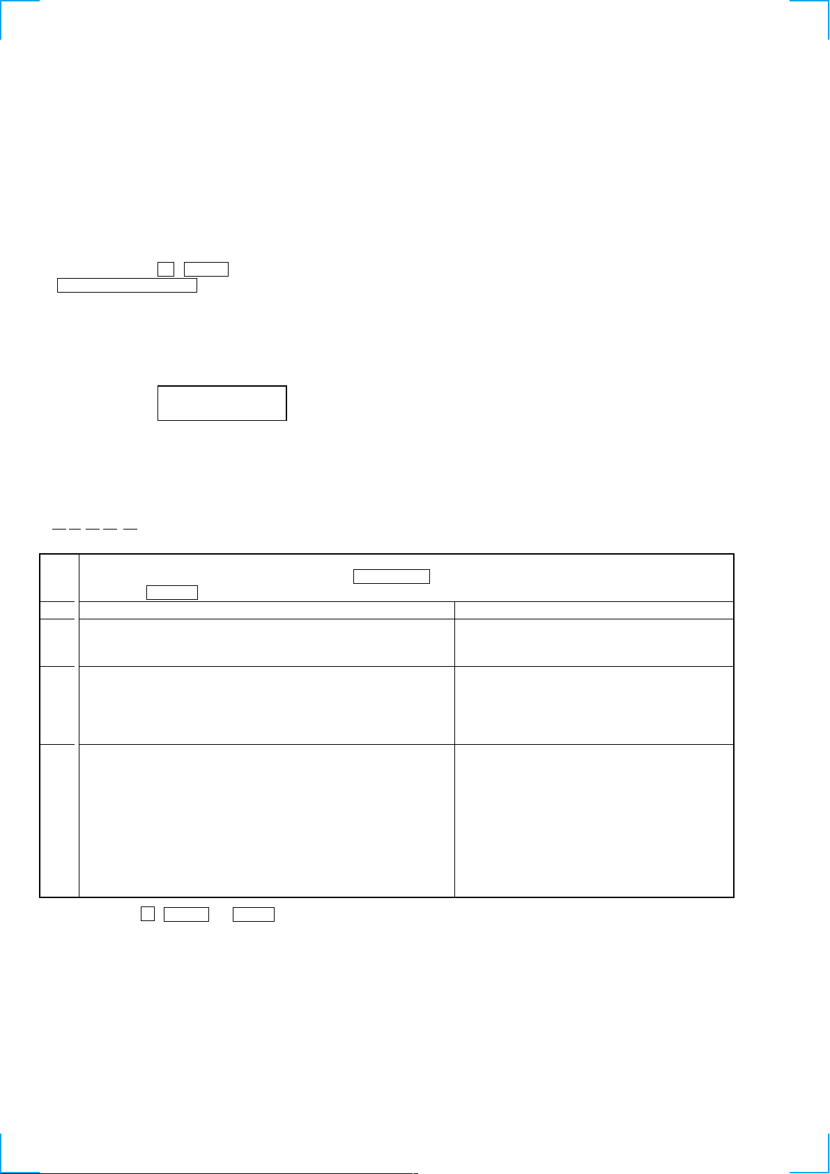
3. Aging Mode in Tape Deck section
1) Display state
• No error occurs
Display action now
• Error occurred
Display action last time
NO. Display action Action contents Final timing
1 TAPE A AG-1 Rewind the TAPE A, B The top of tape
2 TAPE A AG-2 FWD play the TAPE A 2 minutes playing
3 TAPE A AG-3 F.F. the TAPE A 20 second FF or the end
4 TAPE A AG-4 REV play the TAPE A 2 minutes playing
5 TAPE A AG-5 Rewind the TAPE A The top of tape
6 TAPE B AG-2 FWD play the TAPE B 2 minutes playing
7 TAPE B AG-3 F.F. the TAPE B 20 second FF or the end
8 TAPE B AG-4 REV play the TAPE B 2 minutes playing
9 TAPE B AG-5 Rewind the TAPE B The top of tape
of tape
of tape
2) Operation during aging mode
In the aging mode, the program is executed in the following
sequence.
(1) Rewind is executed up to the top of tape A and B.
(2) A tape on FWD side is played for 2 minutes.
(3) FF is executed up to either made for 20 second or the end of
tape.
(4) A tape is reversed, and the tape on REV side is played for 2
minutes.
(5) Rewind is executed up to the top of tape.
(6) Returns to step 2, and repeat steps from 2 to 5.
[Function Change Mode]
* elect either VIDEO or MD of the external FUNCTION input.
Procedure:
1. Turn on the power.
2. Press the two buttons ENTER and ?/1 at the same time.
The main power is turned on and the other function of the
previous function is selected and displayed. “MD” or
“VIDEO”.
15
HCD-BX9/DX9
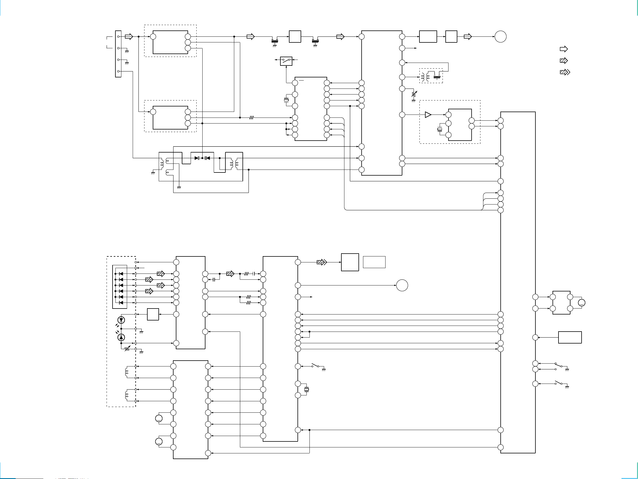
7-2. BLOCK DIAGRAMS
– TUNER/CD SECTION –
FM 75Ω
AM
G
TM601
1
1
1
3
DX9 MODEL
FE601
ANT IN
BX9 MODEL
FE603
ANT IN
RB641
IF OUT
OSC OUT
13
1
FM IF
9
IF OUT
12
AM/IF
24
AM OSC
13
VCO STOP
8
IF REQ MUTE
20
AM RF IN
22
AM OSC
23
V REG
AM/FM IF MPX
IC601
AM MIX OUT
FM SD ADJ
FM/AM DET
TUNED
STEREO
L OUT
R OUT
11
10
18AM IF IN
19
3
16
6
17
BUFFER
Q611
R-CH
IFT601
RV611
IC681
31
XT681
4.332MHz
Q602
Q602
RF IF
AMP
10
1
24
15
18
17
19
FM
XIN
XOUT
FM OSC
VT1 IN
VT1
PD1
PLL
IC651
FM/AM IF
AM OSC
12
FM
7
14
2VCO STOP
8IF REQ
DO
6DO
DI
DI
4DI
CL
CE
CL
5
CE
3
7
8
VT
5
7IF OUT
8OSC OUT
5VT
14
4
55
1511
67
R601
9
CF601 CF602
+B A+12V
X651
4.5MHz
LPF601
LPF
4
14
13
MUX
XO
XI
MODEL
RDS
IC682
DATA
BX9
INT
L-CH
A
MAIN
SECTION
• RCH is omitted
• Signal Path
: FM
(Page 23)
: CD
: DIGITAL OUT
MASTER CONTROL
IC401(1/2)
2
16
21
20
24
23
RDS DATA
RDS INT
TUNED
STEREO
OPTICAL PICK-UP
BLOCK
(KSM-213DAP)
VC
A
B
C
D
E
F
LD
GND
PD
VR
F+
FOCUS
09
COIL
TRACKING
COIL
F-
T+
T-
+5V
Q101
DRIVE
M102
SLED
MOTOR
M101
SPINDLE
MOTOR
22
122
DO
DI
CL
CE
DIGITAL SERVO
DIGITAL SIGNAL PROC.
RF AMP
IC103
12
VC
5
6
7
8
11
10
LD
3
4
MOTOR/COIL DRIVE
13
CH1RO
14
CH1FO
11
CH2RO
12
CH2FO
18
CH3RO
RFO
IC102
RFI
FE
TE
CH1RI
CH1FI
CH2RI
CH2FI
CH3RI
16
17
14
13
22LD ON
21HOLD SW
3
2
6
5
23
A
B
C
D
E
F
LD
PD
D/A CONV.
IC101
D OUT
60
51
RFAC
43
RFDC
L OUT
R OUT
SCLK
SCOR
SQSO
SSTP
XTAI
XTAO
72
75
5DATA
7CLOK
6XLAT
2SQCK
9
20
1
27
66
67
R-CH
X101
16.9344MHz
39
FE
41
TE
40
SE
14
XLON
32
FFDR
33
FRDR
30
TFDR
31
TRDR
29
SRDR
S101
LIMIT
IN SW
IC201
OPTICAL
DIGITAL
OUT
CD
DIGITAL OUT
L OUT
B
MAIN
SECTION
(Page 23)
ST MUTE
27
ST DIN
26
ST DOUT
28
ST CLK
25
ST CE
33
CD DATA
37
CD CLK
42
XLT
33
SQ CLK
19
SCOR
32
SQ DATA
BU UP/DOWN SW
MTR CNT2
T SENS
IC701
44
45MTR CNT1
49
46OPEN SW
47CLOSE SW
48
9
MOTOR
DRIVE
7
TBL ADDRESS
4
2
IC711
SENSOR
OPEN/CLOSE
S701
S711
BU UP/
DOWN
M721
M
TURN
MOTOR
M
17
16
CH3FO
CH4RO
24CH3FI
25CH4INS
28
SFDR
26
MDP
3XRST
43
XRST
M
15
CH4FO
MUTE
20
41
HOLD
22
22
 Loading...