

SONY HCD-CP101 SHEMATICS
http://servis-manual.com/
HCD-CP101
SECTION 4
TEST MODE
[COLD RESET]
• The cold reset clears all data including preset data stored in the
RAM to initial conditions. Execute this mode when returning
the set to the customer.
Procedure:
1. Turn ON the power.
2. Press three buttons of x (TAPE), x (CD), and [BAND] si-
multaneously.
3. The set is reset.
[LIQUID CRYSTAL DISPLAY ALL LIT CHECK MODE]
Procedure:
1. Set to standby state.
2. Press three buttons of x (TAPE), x (CD), and
[TUNING MODE] simultaneously.
3. Liquid crystal display are all turned on.
4. T o exit from this mode, press the I/1 button to turn the power
OFF.
[TAPE DECK AGING MODE]
This mode can be used for operation check of tape deck section.
Procedure:
1. Set a tape in the tape deck.
2. Set to standby state.
3. Press three buttons of x (TAPE), x (CD), and [TUNING +]
simultaneously.
4. The aging is executed in bellow sequence.
5. T o e xit from the a ging mode, press the I/1 button to turn the
power OFF.
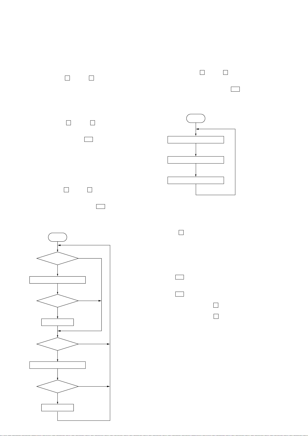
Aging mode sequence:
Start
[CD AGING MODE]
This mode can be used for operation check of CD section.
Procedure:
1. Load a CD disc.
2. Set to standby state.
3. Press three buttons of x (TAPE), x (CD), and [TUNING --]
simultaneously.
4. The aging is executed in bellow sequence.
5. T o e xit from the ag ing mode, press the I/1 button to turn the
power OFF.
Aging mode sequence:
Start
Open the disc tray
Close the disc tray
Play the last track
[CHANGE-OVER MD/VIDEO]
Procedure:
1. Set to standby state.
2. Press the x (CD) and the [FUNCTION] buttons simultaneously.
The function changes over to MD or VIDEO by turns.
FWD Play
1 minute
REC pause for 3 seconds
FWD REC
3 minutes
Fast forward
REV Play
1 minute
REC pause for 3 seconds
REV REC
3 minutes
Shut off
Shut off
Shut off
Shut off
[CHANGE-OVER THE AM TUNING INTERVAL]
(EXCEPT AEP and UK models)
•The AM tuning interval can be changed over 9 kHz or 10 kHz.
Procedure:
1. Press the I/1 button to turn the power ON.
2. Select the function “TUNER”, and press the [BAND] button
to select the BAND “AM”.
3. Press the I/1 button to turn the power OFF.
4. Change over to 9 kHz:
Press the [TUNING --] and the x (CD) buttons simultaneously .
Change over to 10 kHz:
Press the [TUNING +] and the x (CD) buttons simultaneously.
12
Rewind
SECTION 5
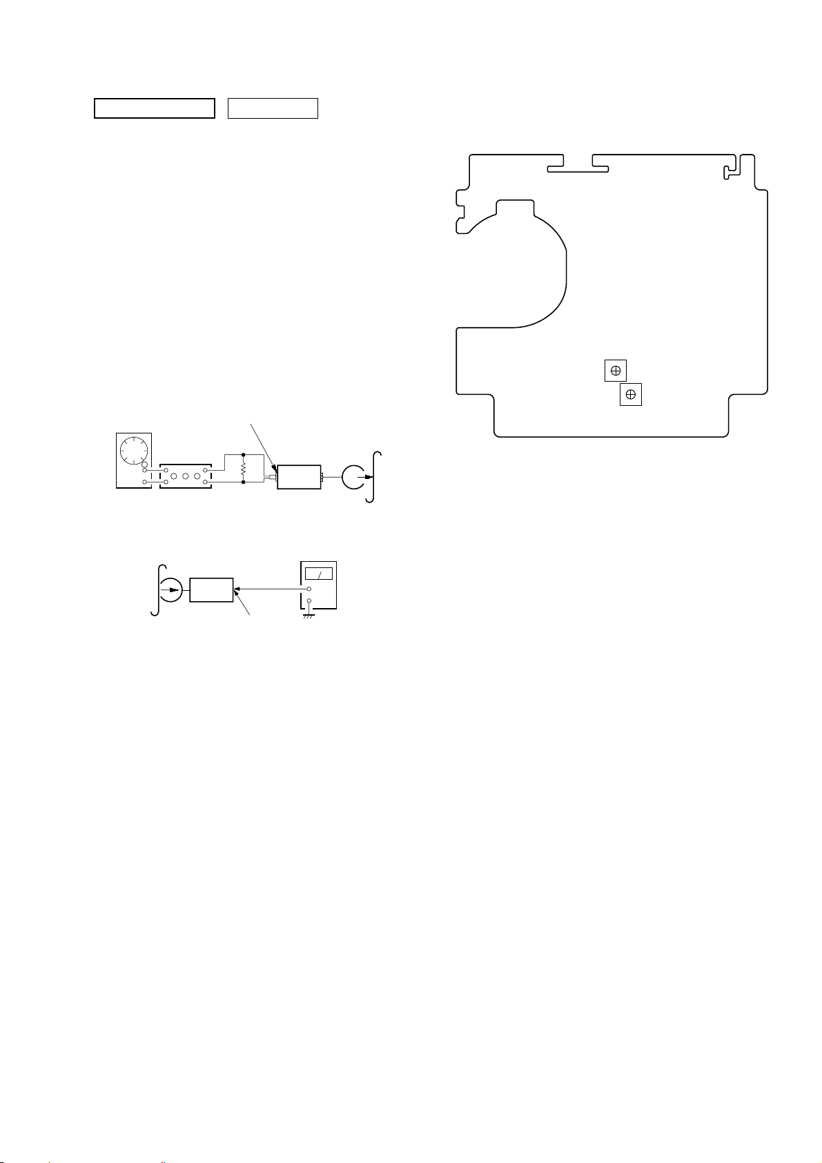
)
RV101 (L)
RV201 (R)
REC Bias
Adjustment
– TC BOARD (Component Side) –
ELECTRICAL ADJUSTMENTS
HCD-CP101
DECK SECTION
Note: Confirm each contents of this section first of all. If the results are
not satisfied, do the adjustment.
0 dB=0.775 V
1. The adjustments should be performed with the rated power
supply voltage unless otherwise noted.
2. The adjustments should be performed in the order given in this
service manual. (As a general rule, playback circuit adjustment
should be completed before performing recording circuit
adjustment.)
3. The adjustments should be performed for both L-CH and RCH.
REC BIAS ADJUSTMENT
Procedure:
1. Mode: REC
FUNCTION: VIDEO
MAIN board
AUDIO IN MD (VIDEO) jack (SJ302)
L-CH, R-CH
50 mV (– 23.8 dB)
600 Ω
set
blank tape
CN-123
AF OSC
1) 315 Hz
2) 10 kHz
attenuator
Adjustment Location:
2. Mode: Playback
recorded
portion
3. Confirm playback the signal recorded in step 1 become speci-
fied values as follows.
If these values are out of specification values, adjust the RV101
(L-CH) and RV201 (R-CH) on the TC board to repeat steps
1and 2.
Specified values: Playback output of 315 Hz to playback output
set
MAIN board
SPEAKER terminals (SJ301
L-CH, R-CH
of 10 kHz: ± 0.5 dB
level meter
+
–
13
HCD-CP101
V
CD SECTION
Note:
1. CD Block is basically constructed to operate without
adjustment.
2. Use YEDS-18 disc (3-702-101-01) unless otherwise indicated.
3. Use an oscilloscope with more than 10 MΩ impedance.
4. Clean the object lens by an applicator with neutral detergent
when the signal level is low than specified value with the
following checks.
5. Check the focus bias check when optical block is replaced.
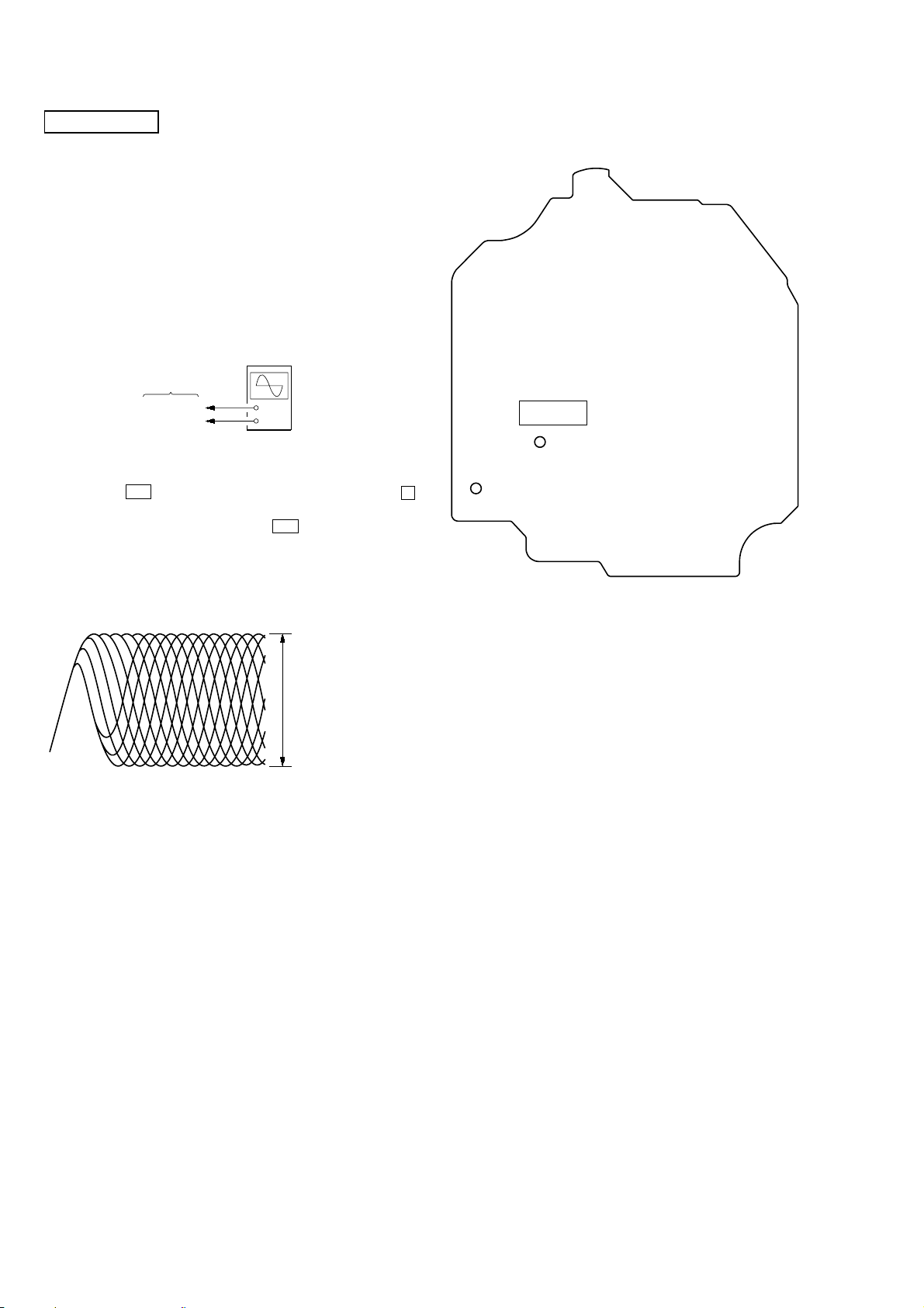
FOCUS BIAS CHECK
oscilloscope
(DC range)
BD board
TP (RF)
TP (VC)
Procedure :
1. Connect oscilloscope to TP (RF) and TP (VC) on the CD board.
2. Press the I/1 button to turn the power on, and press the Z
(CD) button to open the CD disc tray.
3. Put disc (YEDS-18) in and press the u (CD) button to playback.
4. Confirm that oscilloscope waveform is as shown in the figure
below. (eye pattern)
A good eye pattern means that the diamond shape ( ) in the
center of the waveform can be clearly distinguished.
+
–
s
Checking Location:
– CD BOARD (Conductor Side) –
IC103
TP (RF)
TP (VC)
VOLT/DIV: 200 m
TIME/DIV: 500 ns
level:
1.1 ± 0.2 Vp-p
14
 Loading...