

Sony STRDE-845, DAV-700, DAV-900, HCDC-700, HCDC-900 Service manual
...
S
Training Manual
Multi-Product Hi-Fi T echnology and T roubleshooting
Digital Board Hi-Fi Output
Model: STR-DE845 Troubleshooting
Switching Power Supply Super Audio CD
Model: DAV-700/900 New Technology
DAV-S500
HCD-S500
HCD-C700/900
Course: A-124

Table of Contents
1. Introduction ..................................... 1
Purpose............................................................1
Receiver ...........................................................1
Layout ..............................................................1
2. Sound Fields.................................... 2
What is a Sound Field?....................................2
Sound Field Types............................................2
Virtual ...............................................................3
Cinema Studio..................................................6
Semi Cinema Studio.........................................6
Theater.............................................................6
Music................................................................6
Active Speaker Chart .......................................7
Table 2-1 - Input Software Format....................9
3. Digital Board Inputs ....................... 10
Analog Inputs ..................................................10
Digital Inputs ....................................................10
Software Formats Illustrated ...........................12
4. Control Signal Block......................14
Input/Output Select ICs
Control Signal Block........................................ 14
Digital Processing ICs
Control Signal Block........................................ 15
5. Analog signal Block ....................... 19
Circuit Description ...........................................21
6. Digital Signal Block........................ 23
7. Mute Signal Block ..........................25
Regulation .......................................................32
How to Troubleshoot the Power Supply ..........33
Testing the Power Supply Unloaded ...............35
Troubleshooting Shortcuts ..............................36
10. Hi-Fi Output Troubleshooting
Overview .............................................37
11. Troubleshooting Driver
Amplifier & Bias Network Circuits.... 39
Protection light will not go off after replacing
Output transistors............................................39
Excessive Current Draw..................................40
12. Troubleshooting Audio
Protection Circuits ............................. 43
(+/-) Offset Protection Circuit...........................44
Over Current Protection Circuit .......................45
13. Super Audio CD............................ 46
Overview .........................................................46
The New Format for the Age of
Digital Pure Audio............................................46
The DSD Format: No Data Decimination
or Interpolation Required.................................48
Delta Signal Modulation and A/D Converter ....49
Disc Features and Watermark Technology .....5 3
Appendix:
Individual IC
Functional Description ....................... i
IC1201 System Control .................................... i
IC1101 Digital Audio I/F Receiver (DIR) ........... i
8. Troubleshooting Block .................. 26
9. DAV-C700 Switching Type
Power Supply...................................... 28
Safety for You and the Circuit..........................28
Power Supply Operation .................................28
IC1301 Digital Audio Decoder (DAD) ............... i
IC1401 Audio DSP ........................................... i
IC1503 Audio Codec ........................................ i
IC1403 SRAM (Static RAM) ............................. i

1. Introduction
Introduction
Purpose
The focus of this book is on the digital board operation in the sample receiver (STR-DE845) and covers the
following subjects:
• A working understanding of sound fields and what type of movie or music software should be used with
each sound field for optimal performance.
• Proper use of the digital board inputs.
• Which speakers receive actual audio while in various sound field modes.
• Simplified circuit diagram and operation of the digital board for troubleshooting.
To properly troubleshoot the Digital board, a good understanding of what sound fields are and how they affect
the input is essential. Once a good working knowledge of sound fields is obtained, the receiver can be better set
up to process the movie or music software for the best quality audio output. The information in this book will also
help the technician determine whether a customer’s problem is a receiver setup or an actual circuit defect.
Receiver
The main receiver used for demonstration throughout this book is the STR-DE845. The STR-V444ES digital
board will also be covered, showing the DSP circuit changes as compared to the STR-DE845 only. The overall
operation of the digital board in both models is the same.
Layout
Chapter 2 covers the theory and functional description of the various sound fields. Chapter 3 illustrates the
proper use of the receiver (digital board) inputs on the rear panel. Chapters 4, 5, 6 and 7 provide the technician
with block diagram descriptions of the four main systems found on the digital board. Chapter 8 describes a very
practical troubleshooting method for determining a defective component on the digital board. There is also an
appendix at the end of the manual that provides a brief description of the function of the main ICs on the digital
board.
1
2. Sound Fields
Sound Fields
What is a Sound Field?
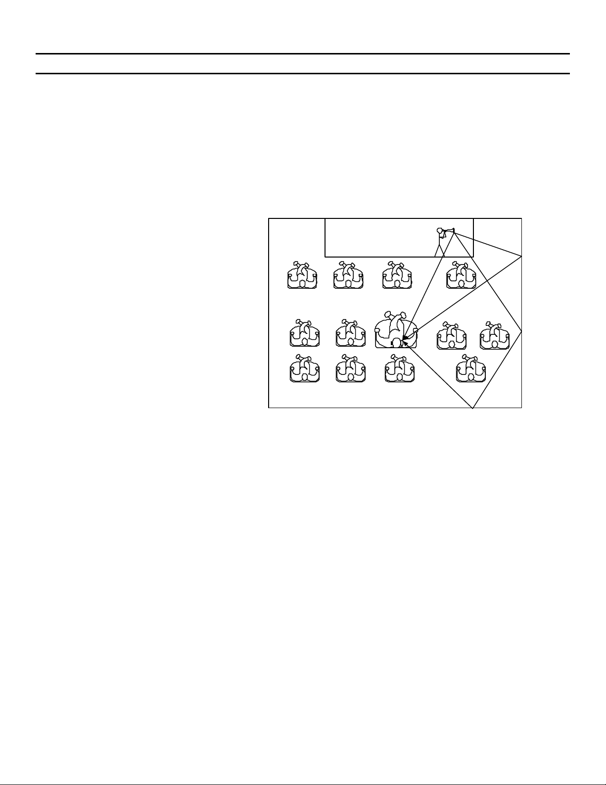
Each venue, be it a concert hall, cinema theater or small jazz club, has a characteristic “sound field” made up of
direct sounds and reflections from the surfaces of the environment. Some venues sound large and spacious,
others sound small and intimate. These characteristics are captured using special microphone pickup systems
placed in the actual venue. The microphone pickup system captures the acoustic blue print of the venue, which
contains all of the acoustic information about the venue, such as direct sounds, early reflections and reverberations
(reverberations occur when the number of reflected sound-waves arriving at the listeners ear becomes very
large; ref. Figure 2-1). All the acoustic data about the venue is stored in the computer and then downloaded to
the A/V receiver’s microprocessor internal memory. So when you select the concert hall sound field on your A/V
receiver, the information stored in the microprocessor’s internal memory is activated and your living room takes
on the characteristics of an actual concert hall.
STAGE
Direct Soundwave
Early Soundwave
Reflection
Late Soundwave
Reflection
Sound Field Types
FIGURE 2-1 - Soundwave Reflection Diagram
Auto Format Decoding (press AFD button)
This mode automatically detects the type of audio signal (Software Format) being input (e.g. Dolby Digital, Dolby
Pro-Logic, or Standard 2 Channel Stereo) and performs the proper decoding if necessary. This mode presents
the sound as it was recorded/encoded, without adding any sound field effects.
NOTE: This mode can be used as a reference. Set the equalizer to “OFF” while using this mode to hear the
source sound exactly as it was recorded. This mode can also be used to determine exactly what type of Software
format is encoded on a given disc.
2 Channel (press 2CH button)
Outputs the sound from the front left and right speakers only. Standard two channel (stereo) sources completely
bypass the sound field processing. Multi-channel surround formats are down-mixed to two channels.
NOTE: No sound is output from the sub-woofer (LFE) when the 2 Channel mode is selected.
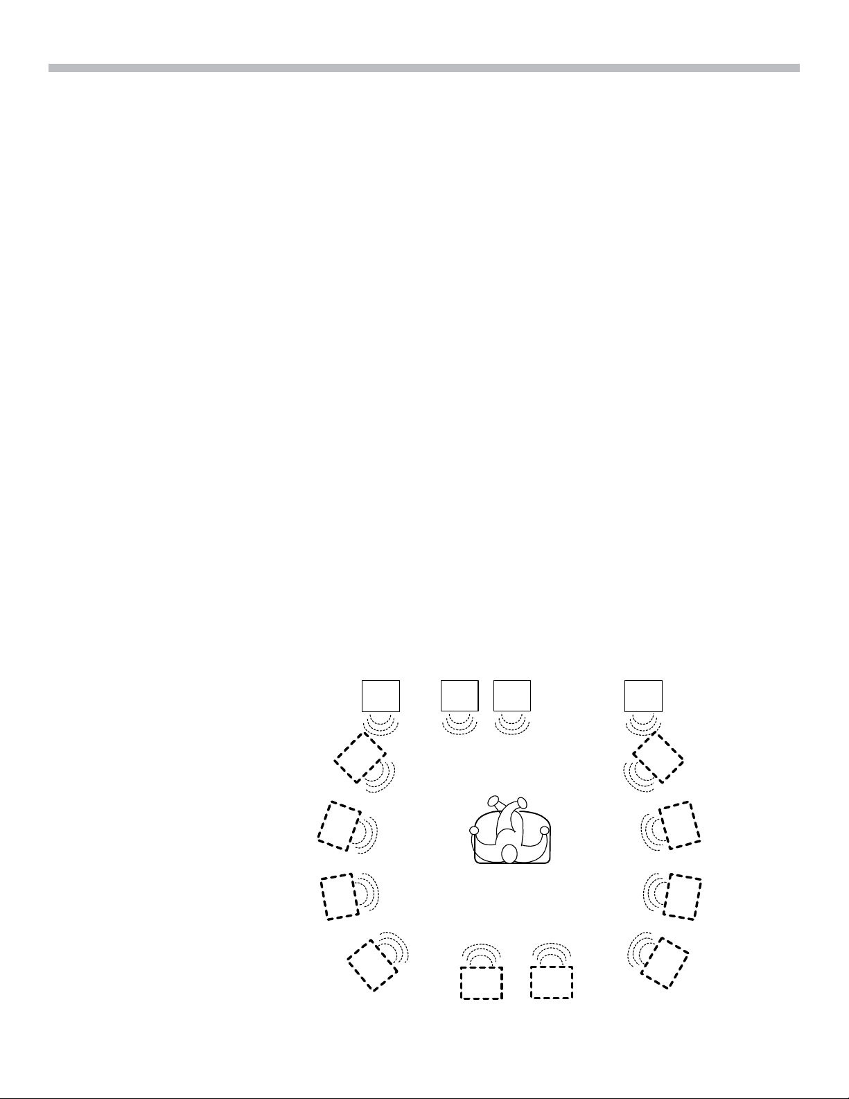
Normal Surround
This mode is designed to be used with a Multi-channel surround audio input (e.g. Dolby Digital/AC-3, DTS or
Dolby Prologic) and the normal six-speaker surround system (front left/right, rear left/right, center and LFE) (ref.
Figure 2-2). When the playback material is encoded with multi-channel surround audio, it will be heard as it was
originally recorded (with no other processing for special effects). For example, a movie will be played back
exactly how the producer recorded it during the movie’s production. If Dolby Prologic (2 channel audio) encode
material is input, it will be processed to create surround sound effects using the actual six-speaker system.
2

2. Sound Fields
FIGURE 2-3 - Rear Speakers Side
FIGURE 2-5 - Rear Speakers Behind
Note:
L RLFE
C
Front Left – FLT
Low Frequency Effects - LFE
Center – Cntr
Front Right – FRT
Rear Left – RLT
Rear Right - RRT
Listening Position – LP
LS RS
FIGURE 2-2
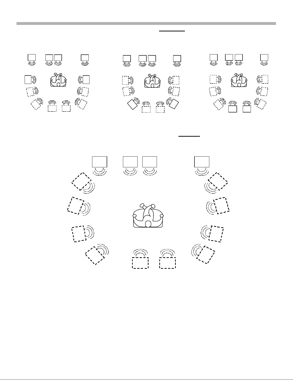
Virtual
The five different Virtual modes create sets of virtual speakers using the actual existing speaker system which
could be a six or three speaker system.
1) V. Multi Dimension: Uses 3D image processing to create four sets of virtual rear speakers surrounding
and positioned at an elevation of 30 degrees higher then the listener from a six-speaker system (two
actual rear speakers). Depending upon where the actual rear speakers are positioned, the virtual speakers
positions will vary (ref. Figures. 2-3, 2-4 and 2-5). The position of the rear speakers (Side, Mid or Rear)
must be programmed in the A/V receiver SET-UP menu for this sound field effect to work properly.
NOTE: The virtual speakers are placed at an elevation of 30 degrees higher then the listener to further
emulate the theater venue. The surround sound speakers in a theater are always higher then the listeners’
position.
LFE
1
LS
LS
2
3
4
4
RCL
1
RS
2
3
1
2
3
FIGURE 2-4 - Rear Speakers Middle
LFE
LS
4
RCL
1
2
3
RS
4
1
2
3
LFE
4
LS
RCL
RS
1
2
3
4
3
2. Sound Fields
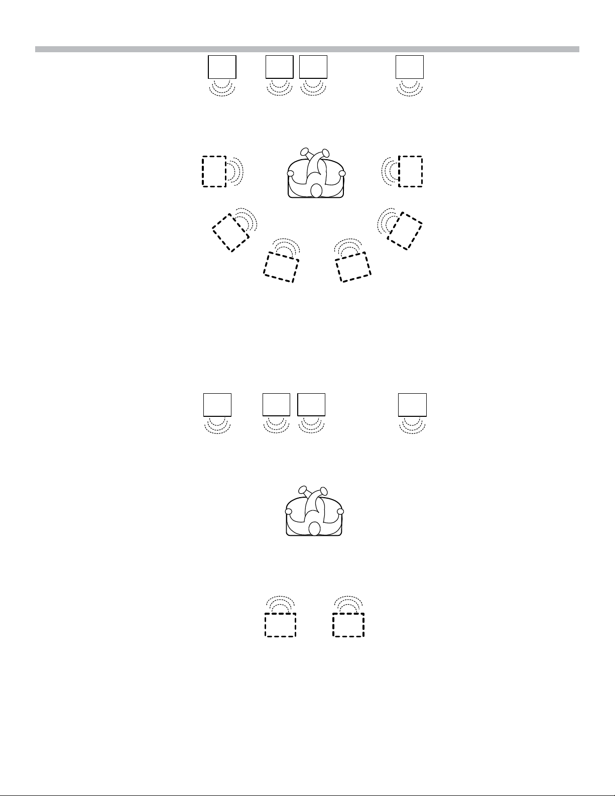
FIGURE 2-9
2) V. Multi Rear: Uses 3D image processing to create three sets of virtual speakers from a six-speaker
system (two actual rear speakers; ref. Figures. 2-6, 2-7 and 2-8). The position of the rear speakers (Side,
Mid or Rear) must be programmed in the A/V receiver SET-UP menu for this sound field effect to work
properly. Note: No 30-degree higher effect.
LFE
LS
1
2
FIGURE 2-6 - Rear Speakers Side
3
3
RCL
RS
1
2
1
2
FIGURE 2-7 - Rear Speakers Middle
LFE
LS
3
3
RCL
1
2
RS
1
2
LFE
3
LS
RS
FIGURE 2-8 - Rear Speakers Behind
RCL
1
2
3
3) V. Semi-M. Dimension: Uses 3D image processing to create five sets of virtual rear/surround speakers
surrounding and positioned at an elevation of 30 degrees higher then the listener. This is accomplished
using only the front left and right speakers without using actual rear speakers (ref. Figure 2-9).
RCL LFE
1
1
2
3
4
5
5
4
2
3
4) Virtual Enhanced A: Uses 3D image processing to create three sets of virtual rear/surround speakers.
This is accomplished using only the front left and right speakers without using actual rear speakers (ref.
Figure 2-10).
4
2. Sound Fields
L
1
2
LFE
3
C
3
R
1
2
FIGURE 2-10
5) Virtual Enhanced B: Uses 3D image processing to create one set of virtual rear speakers. This is
accomplished using only the front left and right speakers without using actual rear speakers (ref. Figure
2-11).
L
LFE
C
1 1
R
FIGURE 2-11
5
2. Sound Fields
p
Cinema Studio
This mode is designed to be used with a Multi-channel surround audio input (e.g. Dolby Digital/AC-3, DTS or
Dolby Prologic) and the normal six-speaker surround system (front left/right, rear left/right, center and subwoofer).
Cinema Studio is similar to Normal Surround except now the acoustical characteristics of a Sony Pictures
Entertainment cinema production studio are present. The 3D image processing of the V. Multi Dimension (a
virtual speaker mode which will be discussed shortly) is added to the normal surround sound audio to produce
the cinema studio atmosphere. There are three Cinema Studio sound fields:
1) Cinema Studio EX. A: Reproduces the sound characteristics of the Sony pictures Entertainment “Cary
Grant Theater” cinema production studio. This sound field can be used when viewing almost any type of
movie.
2) Cinema Studio EX. B: Reproduces the sound characteristics of the Sony pictures Entertainment “Kim
Novak Theater” cinema production studio. This sound field is ideal for viewing science fiction or action
movies with lots of sound effects.
3) Cinema Studio EX. C: Reproduces the sound characteristics of the Sony pictures Entertainment scoring
stage. This sound field is ideal for viewing musicals or classic films where music is featured in the
soundtrack.
Note: The Cary Grant and Kim Novak S tudios are actual Sony Pictures Entertainment Movie Production Studios
where a movie is shot and produced. Each has its own unique acoustical characteristics, which in these cases
even have particular characteristics for certain types of movies (e.g. The Kim Novak Studio is particularly good
for Science Fiction movies). The Sony Entertainment Scoring Stage is an actual studio used for recording the
music portion of the movie. Once again, this studio has especially good characteristics for recording movie
sound tracks. This makes this mode particularly good for playing back certain movies where the sound track is
a major part of the movie (e.g. a musical movie).
Note: These sound fields use the 3D sound imaging of V. Multi Dimension. Reference figures 2-3, 2-4 and 2-5
for the three possible virtual speaker system positioning, which depends on the positioning of the two actual rear
speakers.
Semi Cinema Studio
These three sound fields (Semi Cinema Studio EX. A, Semi Cinema S tudio EX. B and Semi Cinema S tudio
EX. C) are identical to the above Cinema Studio mode except now the Sony Picture Entertainment cinema
production studio sound characteristics are reproduced using only front left, right and center speakers. All other
speakers are virtual (ref. Figure 2-12).
L
1
2
3
LFE
C
R
1
2
3
4
5
FIGURE 2-12 - Listener, Actual and Virtual Speaker Setu
5
6
4

2. Sound Fields
Theater
There are four theater sound fields:
1) Night theater: Retains theater-like sound characteristics while listening at a low volume level, ideal for
late night movie viewing.
2) Mono Movie: Creates theater-like sound characteristics from movies with mono soundtracks.
3) Stereo Movie : Creates theater-like sound characteristics from movies with stereo soundtracks.
4) Headphone theater: Retains theater-like sound characteristics while listening through a pair of
headphones.
NOTE: Mono Movie and Stereo Movie modes do not convert input signals to Mono or Stereo signals.
They are strictly used for optimal playback of analog 2ch movie soundtracks.
Music
Nine different sound fields reproduce the acoustical characteristics of nine different venues. Each one of these
sound fields is designed for a 2-channel stereo input (e.g. from a CD, DAT, TV Broadcast, etc.). Some of these
sound fields are designed to perform better with certain types of music (e.g. Jazz Club with Jazz, Rock music
with Live House and so on). These sound fields are listed below:
Small Hall Church
Large Hall Live House
Opera House Arena
Jazz Club Stadium
Disco Club
Video Games
Game: This sound field is designed to be used with video game software and a stereo input. This mode will
produce dynamic audio while playing video games.
Active Speaker Chart
With so many sound fields and software formats, it can be very difficult to know which speakers are active (actual
audio applied to them by the receiver) for the software while in a particular sound field mode. Chart 2-1 on the
following page shows Sound Fields on its vertical axis and Software Formats on the top horizontal axis. It
indicates which speakers are active with the chosen Sound Field and Software Format. This chart also indicates
when Virtual Speakers are present. To get the same results as this chart at any location, the following conditions
must be met:
Conditions
1) The input device (e.g. DVD, CD etc.) must be set up properly to output the desired Software Format (e.g.
AC-3, DTS etc.).
2) The proper input on the receiver must be used to receive the desired Software format.
a. Optical and Coax Inputs: Dolby Digital (AC-3), DTS, Dolby Prologic, Dolby Surround and PCM
b. Analog Inputs: Dolby Prologic, Dolby Surround, Stereo and Mono
c. 5.1 Channel Input: This input bypasses all surround sound processing of the receiver. Note:
This is a good input to use to test if all the speakers in the system are receiving audio. The
input device must have a 5.1 Channel output.
7

2. Sound Fields
3) Speaker wires must be connected correctly, e.g. the Positive (+) on the receiver terminal connected to the
Positive terminal on the speaker. Same for the Negative (-) terminal.
4) The speaker impedance switch on the receiver should match the impedance of the speakers connected.
Note: If only output “A” is used, the impedance switch should be set to match the speaker
impedance (e.g. 4 or 8 ohms). Caution!!! - If the “A” and “B” output are used simultaneously, the
impedance of each speaker must not be less then 8 ohms and the impedance switch must be set
for 4 ohms. This is because the speakers are placed in parallel when in this configuration so the
impedance of the speakers is cut in half.
Notes for Chart:
1) The box around the speaker letter indicates that this is an actual physical speaker (not virtual) and
audio is applied to the speaker.
2) There are notes under pictures to indicate if virtual speakers are being created.
NOTE: The actual rear surround sound speakers will be inactive in the following sound field modes:
• Semi-Cinema Studio EX. A, B, and C
• V. Semi-M Dimension
• Virtual Enhanced A and B
• 2 Channel
8
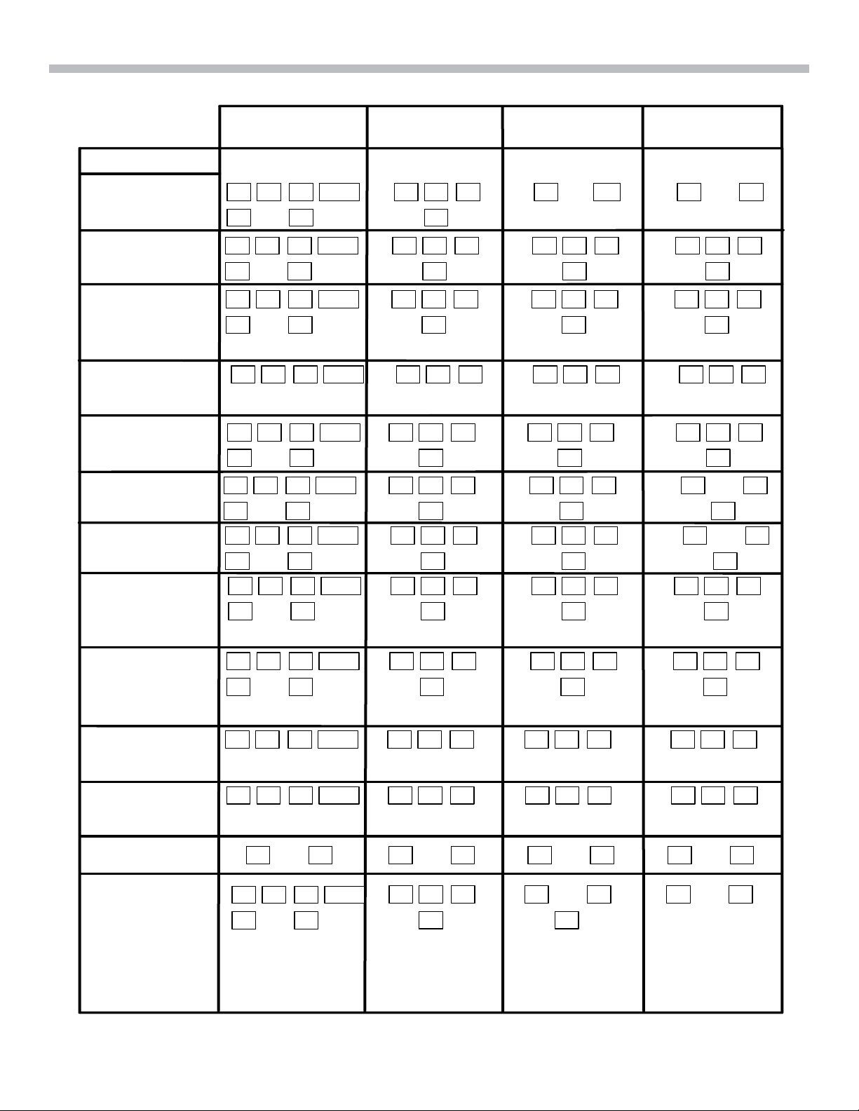
TABLE 2-1 - INPUT SO FTWARE FORMAT
2. Sound Fields
Sound Field
A.F.D.
Normal Surround
Cinema Studio
Ex. A, B, C
Sem i-Cinema Studio
Ex. A, B, C
Night Theater
Mono Movie
¾ Dolby Digital (AC-3)
¾ 5.1 Chanel Surround
¾ DTS
LS RS
L C R LFE
LS RS
L C R LFE
LS RS
W ith additional virtual
speaker
L C R LFE
All other speakers
virtual
L C R LFE
LS RS
L C R LFE
LS RS
Dolby Prologic PCM
L C R
S
L C R
S
L C R
S
L C R
All other speakers
virtual
L C R
S
(reve rb)
L C R
S
(reve rb)
L R L RL C R LFE
L C R
L C R
L C R
All other speakers
virtual
L C R
L C R
¾ Stereo
¾ Mono
L C R
S
S
All other speakers
virtual
S
S
S
L C R
S
L C R
L C R
S
L R
S
Stereo M ovie
V. Multi
Dimension
V. Multi Re ar
V. Sem i - M
Dimension
Virtual Enhanced
A, B
2 Channel
Sm all Hall
Large Hall
Opera House
Jazz Club
Disco Club
Church
Live House
Arena
Stadium
Game
This table shows which speakers are active during a particular sound and software format input.
L C R LFE
LS RS
L C R LFE
LS RS
With additional
virtual speakers
L C R LFE
LS RS
W ith additional
virtual sp e ak e rs
L C R LFE
All other speakers
virtual
L C R LFE
All other speakers
virtual
L R L R L R L R
L C R LFE
LS RS
L C R
S
(reve rb)
L C R
S
L C R
S
L C R
All other speakers
virtual
L C R
All other speakers
virtual
L C R
S
L C R
S
L C R
S
L C R
S
L C R
All other speakers
virtual
L C R
All other speakers
virtual
L R
S
L R
S
L C R
S
L C R
S
L C R
All other speakers
virtual
L C R
All other speakers
virtual
L R
9

3. Digital Board Inputs
Digital Board Inputs
Analog Inputs
2 Channel Stereo Inputs
There are nine analog inputs on the digital board. They are as follows:
- Tuner
- Phono
- CD
- MD/Tape
- TV/SAT
- DVD/LD
- Video 1, 2, 3
These inputs enter the digital board as analog audio and supply one of the following audio formats: Mono, S tereo
or Dolby Prologic. They go through a switching IC and then onto the Audio CODEC to be digitized. The digital
data stream is applied first to the Audio Decoder and then to the Audio DSP, which processes and applies the
effects of the chosen sound field.
5.1 Channel Input
The 5.1 Channel Input is a full surround sound analog audio input that bypasses the sound field processing of
the digital board in the receiver. All the surround sound processing required to produce the 5.1 Channel Input is
performed by the device connected to this input, such as a DVD player with a 5.1 Channel Output. The 5.1
Channel Input is applied directly to the output selector IC1502. IC1502’s outputs are connected directly to the
amplifier system. The 5.1 Channel Input actual consists of six signals: Front Left, Front Right, Rear Left, Rear
Right, Center and Subwoofer. The Subwoofer is the “1” in the 5.1 designation.
Digital Inputs
There are two types of digital inputs - the Optical input and the Coaxial input. The only dif ference between these
two inputs is the medium used to transfer the signal between devices. The Optical input utilizes Fiber Optic cable
to transmit data as light pulses down a glass fiber center conductor. Because light pulses are used, the Fiber
Optic cable is virtually immune to any external electrical interference, making it the preferred digital signal source.
The Coaxial Input uses Coaxial cable similar to that found in Cable TV connections. It consists of a copper
center conductor, a foam insulator and an outer braided wire shield. The Coaxial cable has good external noise
immunity characteristics, but cannot compare to the Fiber Optic cable. Also, the bandwid th characteristic of the
Fiber Optic cable is much greater. Both of these input types are digital, using the same data protocol (S/P DIF
format). There are three Optical inputs, one Optical Output and one Coaxial input on this receiver.
Optical: Coaxial:
DVD/LD input DVD/LD
TV/SAT input
DAT/MD input
MD/DAT output
10
3. Digital Board Inputs
Table 3-1 – Digital Input Sampling Frequency Compatibility
Input Sampling Frequency
Optical DVD/LD 96KHz, 48KHz, 44.1KHz, 32KHz
Optical TV/SAT 48KHz, 44.1Khz, 32KHz
Optical DAT/MD 48KHz, 44.1Khz, 32KHz
Coaxial DVD/LD 96KHz, 48KHz, 44.1KHz, 32KHz
NOTE: If a signal with a sampling rate of 96kHZ is applied to the MD/DAT or TV/SAT inputs, intermittent
audio at the receiver outputs may occur.
These digital inputs are sent through the complete surround sound processing circuitry of the digital board to
produce the 5.1 Channel Output signals. This processing and signal flow will be discussed in detail in the next
chapter.
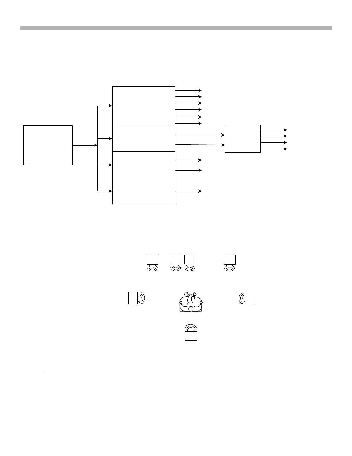
ANALOG
INPUTS
DEVICES
DVD
MULTI-CHANNEL DECODE
NOTE: THE DEVICE MUST BE CAPABLE OF
PROCESSING AC-3,OR DTS SOFTWARE AND
OUTPUT 5.1 CHANNEL SIGNALS
DIGITAL INPUTS
REAR
FRONT
CENTER
L
R
SUB
WOOF
DEVICES
MD/DAT
TV/SAT
DEVICES
DVD/LD
DVD/LD
(COAX)
SOFTWARE
FORMATS
DOLBY DIG ITAL
AC-3 (5.1)
DTS (5.1)
DOLBY PROLOGIC
PCM 48kHz, 41.1kHz,
32kHz
SOFTWARE
FORMATS
DOLBY DIGITAL
AC-3 (5.1)
DTS (5.1)
DOLBY PROLOGIC
PCM 96kHz, 48kHz,
41.1kHz, 32kHz
DIPOLE
WIRE
ANTENNA
STR-
DE845
(REAR
VIEW)
ANALOG
INPUTS
ANTENNA
AM
COAXIAL
FM
75
Ω
SIGNAL
GND
L
R
IN
IN
PHONO CD
L
R
FRONT
5.1 CH INPUT
OUT
MD/DAT
REAR
CTR S
IN
IN
CENT.
WOOF.
S-VIDEO
VIDEO
OUT
MONITOR
SUB
OUT
OUT IN
MD/DAT
CTR S
STAT.IN
TAPE
OPTICAL
MD/DAT
OUT
S-VIDEO
IN
IN
VIDEO
IN
AINA
TV/SAT
TV/
SAT
IN
DVD/LD IN
DIGITAL
S-VIDEO
IN
VIDEO
IN
IN
DVD/LD
CTR S
OUT
VIDEO OUT
AUDIO OUT
COAX
DVD/LD
IN
CTR S
OUT
VIDEO IN
A
VCR
IN
S-VIDEO
OUT
VIDEO
OUT
AUDIO OUT
S-VIDEO
VIDEO IN
DOLBY SURROUND DOLBY PROLOGIC STEREO MONO
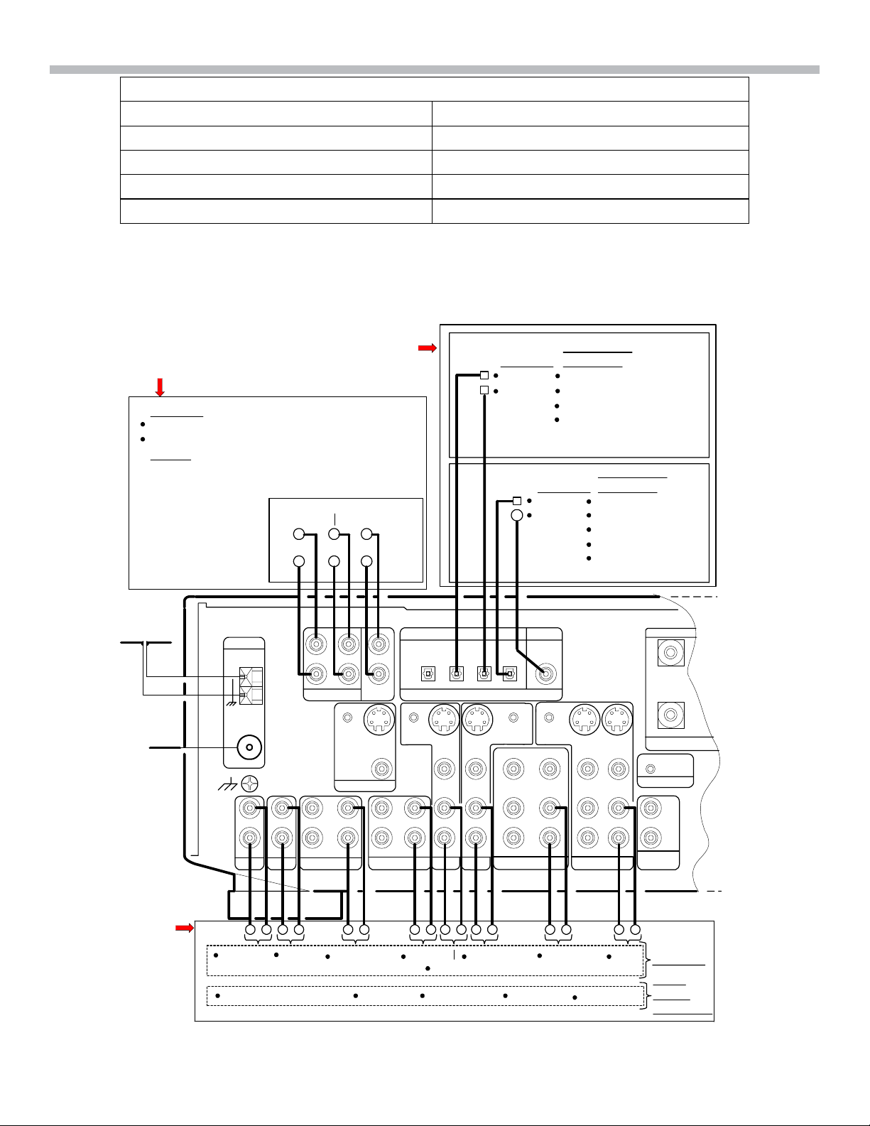
FIGURE 3-1 - STR-DE845 ANALOG & DIDITAL INPUTS
IN
VCR
IN
2ND AUDIO
CONTROL AII
SPEAKERS
+
B
R
-
OUT
DEVICES
SOFT
WARE
FORMATS
IMPED
10/15/0113CA124 1380
11
3. Digital Board Inputs
Figure 3-1 illustrates the typical devices connected to the various receiver inputs and what software formats are
compatible with each input.
NOTE: The audio from the Tuner antenna section is also an input to the digital board. It is processed the same
as any of the other analog inputs in order to apply the desired sound field effects. The input signals to the tuner
are off the air (FM and AM) signals. There is also an analog Video 3 Input on the front panel of the receiver that
can accommodate another VCR.
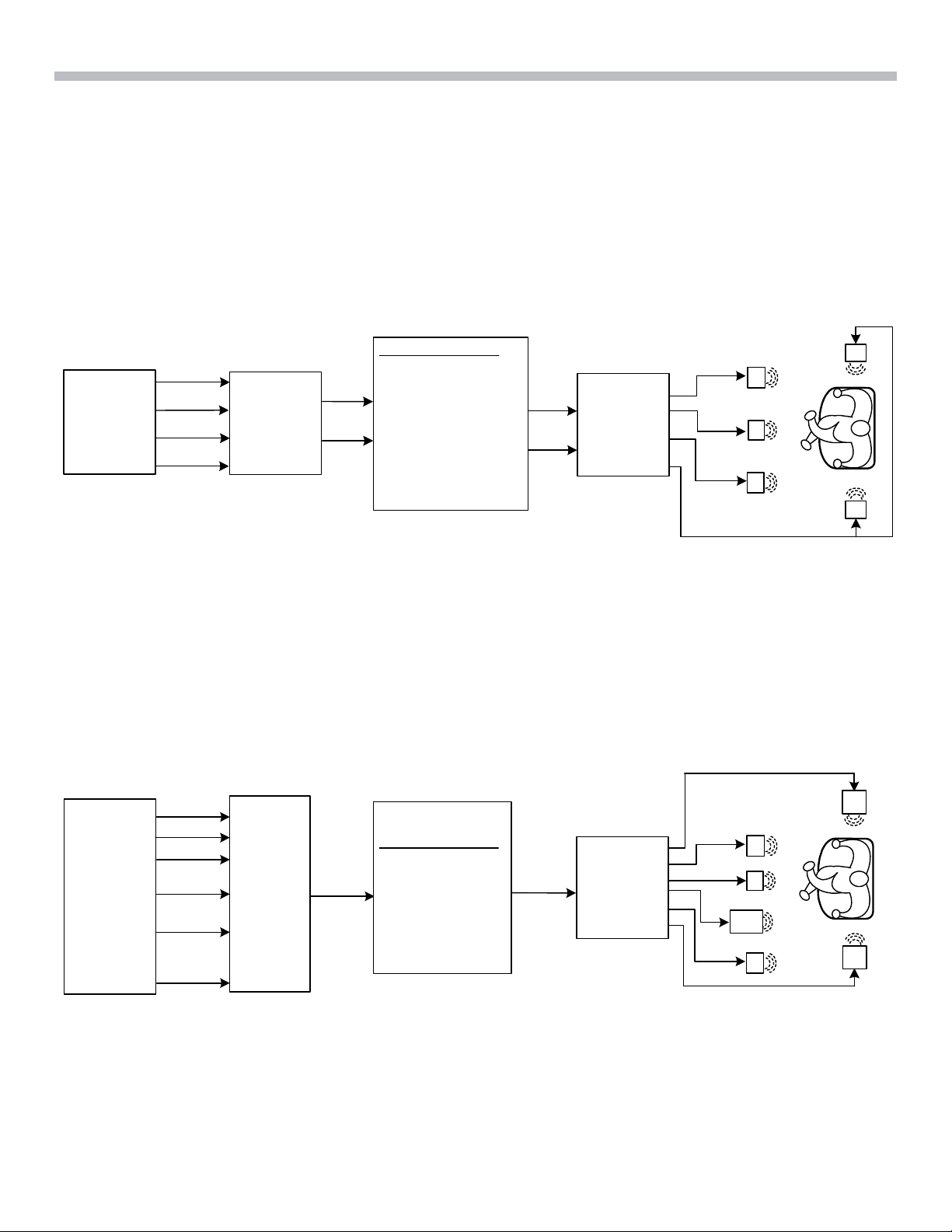
Software Formats Illustrated
Dolby Surround Prologic
Left
Four
Channel
Signals
Note: From a live performance
or recording
Right
Center
Surround
Dolby
Surround
ProLogic
Encoder
Software Medium
y Laser Disk
LT
RT
y DVD Disk
y CD
y VHS Tape
y Cassette Tape
y Cable
y Satellite TV
y Regular Tv
DOLBY SURROUND PROLOGIC
LT
RT
Dolby
Surround
ProLogic
Decoder
L
C
R
S
S
FIGURE 3-2
Figure 3-2 illustrates the encoding and decoding of a Dolby Surround Prologic format. Note that this format can
be encoded on the software medium (DVD disk, VHS tape etc.) in a digital data stream or analog signal. The
original four channels are encoded into two channels (Left Total and Right Total). At the decoder, the twochannel signal is decoded back to the original four channel surround signals (Left, Right, Center and Surround).
Also note that the surround signal in the Prologic format in fed to both rear speakers, so both speakers receive
equal signals. There is a slight delay in time as compared to the front speakers.
Dolby Digital (AC-3), and DTS
Left
Center
Right
5.1
Channel
Signals
Note: From a live performance
Left
Surround
Right
Surround
Low
Freq.
Effect
or record i ng
Dolby
Digital
or
DTS
Encoder
Digital
Data
Stream
Software Medium
y Laser Disk
y DVD
y Cable
y Satellite TV
y Regular TV
DOLBY DIGITAL & DTS
Digital
Data
Stream
FIGURE 3-3
12
Dolby
Digital
or
DTS
Decoder
LFE
RS
L
C
R
LS
3. Digital Board Inputs
Dolby Digital; EX (6.1)
Figure 3-3 illustrates the encoding and decoding Dolby Digital and DTS 5.1 channel formats. These formats are
encoded into a digital data stream only, such as a DVD disc, Satellite signal, etc. (no analog encoding). There
are actually six channels in the 5.1 channel format (Left, Right, Center, Subwoofer or LFE, Left surround and
Right surround). Note that the rear speakers are now fed totally separate surround signals that provide a
superior separation between the speakers when sounds are traveling around the system. Also added to this
format is the Low Frequency Effects (LFE) or Subwoofer signal.
5.1 Channel format compatibility
L
C
Dolby Digital
or
DTS 5.1 Channel
Data Stream
Decoder "A"
Decoder "B"
Decoder "C"
R
LS
RS
LFE
LT
RT
L
R
5.1 Channel
Signals
Two Channel
Stereo Signals
Dolby
Prologic
Decoder
L
C
R
S
Four Channel
Dolby Surround
signals
Decoder "D"
Mono Signal
FIGURE 3-4 - 5.1 Channel Downmixing
Figure 3-4 illustrates that the 5.1 Channel format is compatible with all of the other formats. The 5.1 channel
signal as shown can be DOWN-MIXED into any other format depending on the decoding applied. This is similar
to the Prologic format, which is compatible with stereo and mono system due to the way it is encoded.
New Development in Digital Surround Technology
Dolby Digital Surround EX (6.1)
LFE
LS RS
CS
FIGURE 3-5
RCL
A center screen channel (or speaker) is necessary to ensure the precise localization of the front sounds for the
viewers. Dolby Digital Surround EX brings similar benefits to the surround sound field (side or rear speakers).
With Dolby Digital Surround EX, a center surround channel is reproduced. This speaker driven by the center
surround channel is positioned at the back/center of the listening room. Left and right surround sound is still
reproduced by the side speakers (Ref. Fig. 3-5). This means that sounds can now be positioned behind the
audience, opening the door to exciting new effects such as true 360-degree pans. The center surround channel
also makes front-to-back and back-to-front transitions more realistic. Dolby Digital Surround EX is fully compatible
with the current 5.1 Channel digital formats, and will play back normally on current 5.1 systems. Dolby Digital
Surround EX basically adds a center surround channel to 5.1 digital formats.
13
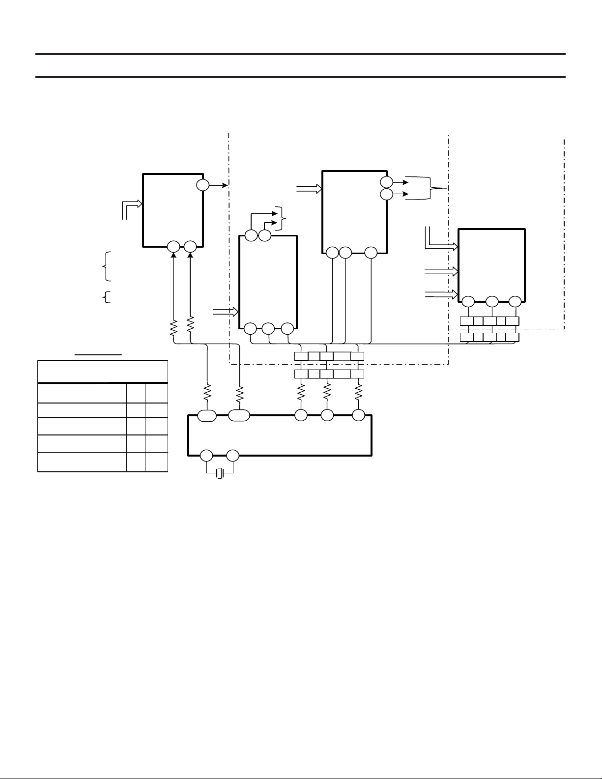
Control Signal Block
Input/Output Select ICs Control Signal Block
4. Control Signal Block
DIGITAL BOARD
DIGITAL
INPU TS
FROM
OPTICAL
COAXIAL
TABLE 4-1
IC1005 CONTROL LINES
PIN No.
(COAX) DVD/LD
(OPTICAL)TV/SAT
(OPTICAL)DAT/MD
(OPTICAL) DVD/LD
IC1001
IC1002
IC1003
J1001
A
2
10
01
11
0
IC1005
DIGITAL
INPUT
SELECT
R1007
B
14
0
2 14
AB
ANALOG
R1282
7
INPU TS
REAR
PANEL
JACKS
R1006
108
A
93 92
ANALOG INPUTS
REAR PANEL
TO
IC1101/
PIN 3
SDI
107
SYSTEM CONTRO L
JACKS
R
L
12 17
IC30 1
ANALOG
INPU T
SELECT
15 16
14
CLK
CNS306
CNS5
R1281
B
IC1201
X1201
16MHz
TO
IC304/
PINS 3
& 5
CE
3 5 4
19 17 18
47 48 46
SDI
DIGITAL BOARD
MAIN BOARD
IC30 3
ANALOG
INPU T
SELECT
15 14 16
CLK
SDI
CLK
CE
L
12
17
R
2 CH. MODE
FROM IC 3 0 4
EXTERNAL
5.1 CH.
J307
5.1 CH.
INPUT
FROM
IC1503
CE
AU SW BO ARD
TO IC 30 4/
PINS 3 & 5
IC1502
OUTPUT
SELECT
15 14 16
SDI CLK
2 1 3
19 AC 18
CE
FIGURE 4-1
DIGITAL BOARD
INPU T/OUTPUT
SELECTOR ICs
CONTROL BLOCK
1A124 1365
11/20/01
CNP11
CNP301
Circuit description
NOTE: Reference Figure 4-1 for the following circuit description:
Data, Clock and Chip Enable Lines
All control signals are supplied by IC1201 (System Control). IC1201/Pins 108 and 107 control the digital input
selection of IC1005 (pins 2 and 14). These control lines are a simple two-bit input. Table 4-1 shows the two-bit
code for the corresponding input. The resistors on the output of IC1201 (R1282 and R1281) and on the input of
IC1005 (R1006 and R1007) are easy probe points to confirm the bit pairs in the table.
The control lines for IC301, IC303 (analog input select ICs) and IC1502 (output select IC) are at IC1201/pins 46
(CE), 47 (Data) and 48 (CLK). These control signals are somewhat difficult to view due the fact that they are only
present while switching between inputs via the front panel buttons of the receiver. However, the main concern
here is that there is communications between ICs and that the actual inputs do change. Waveforms 4-1, 4-2 and
4-3 illustrate how the waveforms will appear on the oscilloscope while switching between inputs (e.g. Video 1,
Video2, DVD/LD etc). Once again, these are not exact waveforms. Confirmation of data communications
between ICs and data amplitude (5Vpp) are the important factors. All three pins (IC1201/46, 47 and 48) are at a
low state (0V) while waiting for a button to be pressed (standby state).
14
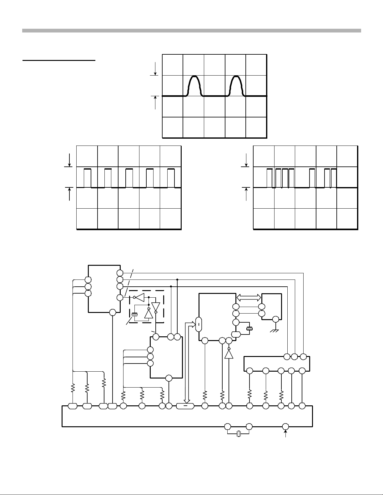
Data and Control Line Waveforms for IC1301 and IC502
Oscilloscope Settings:
5v/div.
4. Control Signal Block
100us/div.
DC coupling
PIN No.46
CE
(R1202)
5Vp-p
Trigger rising edge
WAVEFORM 4-1
PIN No.48
CLK
5Vp-p
(R1204)
WAVEFORM 4-2
Digital Processing ICs Control Signal Block
12.282MHz
I/F
RST
111 100110112
13
14
15
22
48
X3501
12.282
MHz
R1265
1 2 3 5
IC1201 SYSTEM CONTROL
IC1404
12.282
MHz X1401 10MHz
CLK
SDI
CE
69
68
66
R1270
R1275
LR
CLK
8
82 83
IC1301
DOLBY
DIGITAL
AUDIO
DECODER
RST
62
PDI
16
25
HAD
R1263
24
17
R1289
SDI
CLK
CE
IC1101
36
DIGITAL
38
AUDIO
37
RECEIVER
R1288
R1286
PIN No.47
DATA
(R1203)
IC1401
AUDIO
DSP
15 14 26
CE
R1252
25 16 26
CE
HAO
5Vp-p
BCLK
LRCLK
DATA
WE
74
70
OE
97
100
RST
IC1202
R1242
CDTORST
93 92 90
IC1402
SRAM
17
41
6
IC1503AUDIOCODEC
43 1141 1742
R1245
30 3528 3229
CLKCLK RSTCLK RSTCESDO SDOCE PDO
CECLKCDTI
R1285
CE
WAVEFORM 4-3
MCLK
5 4 39
96
RST
KHz
96
RST
KHz
X1201
16MHz
RST FROM Q108
DISPLAY BOARD
FIGURE 4-2 - DIGITAL BOARD PROCESSING IC's CONTROL BLOCK
15
2A124 1367
11/20/01
4. Control Signal Block
Circuit Description
Data, Clock, and Chip Enable Lines
The control lines for IC1401 (IC1201/parallel data lines 17 to 24, pin 25 (address line) and pin 16 (CE)) and
IC1503 (IC1201/pins 30 (data), 29 (CLK) and 28 (CE)) are only present during input switching. The waveforms
on the control lines are the same as those shown in Waveforms 4-1, 4-2 and 4-3, except standby voltage state
is high (5V dc).
The waveforms on the control lines for IC1101 (IC1201/pins 112 (data), 110 (CLK), and 111 (CE)), and IC1301
(IC1201/pins 1 (CLK), 2 (data), and 3 (CE)) are always present as digital data is present at one of the digital input
jacks (optical or coax). Waveforms 4-4 and 4-5 illustrate what is displayed on the oscilloscope. When the Input
mode is set to Analog input, all three control lines on IC1101 are inactive and the chip select line on IC1301 is
inactive (the other two lines on IC1301 are active with data, but the chip is not enabled).
The following waveforms can be viewed on the oscilloscope continuously when digital data is present at the
digital inputs and that digital input is selected.
Oscilloscope Settings:
5V/div.
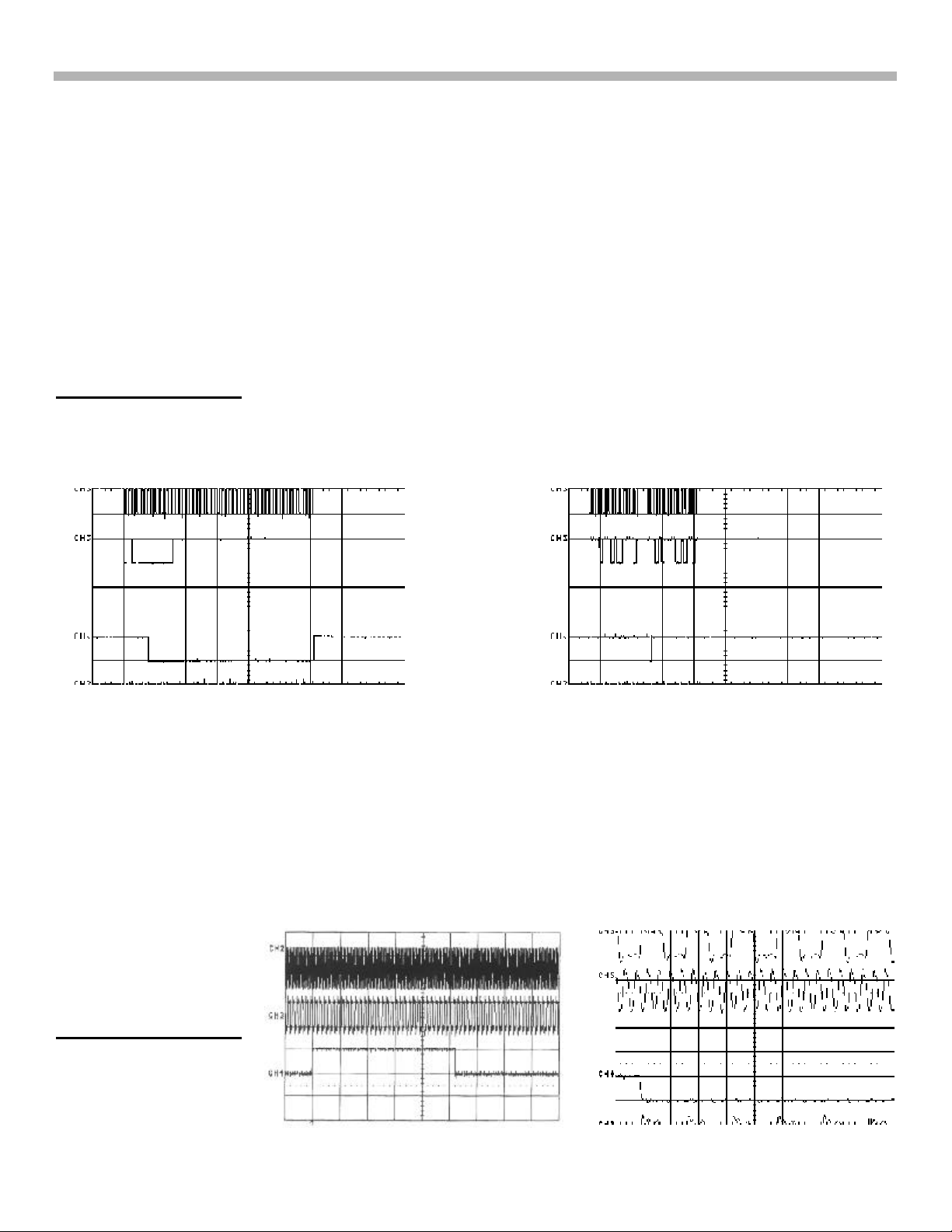
Data and Control Line Waveforms for IC1101
100us/div or 50us/div
Trigger rising edge
DATA
CLK
CE
WAVEFORM 4-4
DATA
CLK
CE
WAVEFORM 4-5
Master, Bit and Left/Right Channel Clock lines
All the control lines discussed so far are used either for input/output switching or to set up an IC for a particular
function (e.g. Dolby Digital decoding). The Clock lines that will be looked at now are used for data manipulation.
The Clock lines MCLK (Master Clock), BCLK (Bit Clock) and LRCLK (Left Right channel Clock) are all developed
by IC1101 using X3501 (12.282MHz). The MCLK is applied only to IC1503 (CODEC), while BCLK and LRCLK
are applied to IC1301 and IC1503. These Clock lines are used to synchronize the system to the incoming audio
data stream so that appropriate decoding and coding can be performed. The following waveforms are always
present and can be viewed easily with the oscilloscope. Waveform 4-7 is an expanded view of Waveform 4-6.
The frequency for each clock signal is as follows:
MCLK —— 12.282MHz
BCLK —— 3MHz
LRCLK — 48KHz
Oscilloscope Settings:
5V/div.
2us and 200ns/div
Trigger rising edge
MCLK
BCLK
LRCK
WAVEFORM 4-6
MCLK
BCLK
LRCK
WAVEFORM 4-7
16
4. Control Signal Block
Reset lines and Crystals
The main Reset line is applied to IC1201/pin 90. During normal operation, this line is High (5V dc).
The other Resets are output to IC1101/ pin 48 (normal high 5V), IC1301/pin 62 (normal high 5V), IC1503/pin 17
(normal high 5V) and IC1401/pin 26. This output is Low (0V), but it passes through inverter IC1202 and a High
(5V) is applied to IC1401. The crystal frequencies and amplitudes are shown in Table 4-2 below:
Table 4-2 – Crystal Frequencies and Amplitudes
IC Ref. Number Crystal Ref.
IC1101 & 1301 X3501 12.282MHz 4Vpp
IC1401 X1401 10MHz 3Vpp
IC1201 X1201 16Mhz 4Vpp
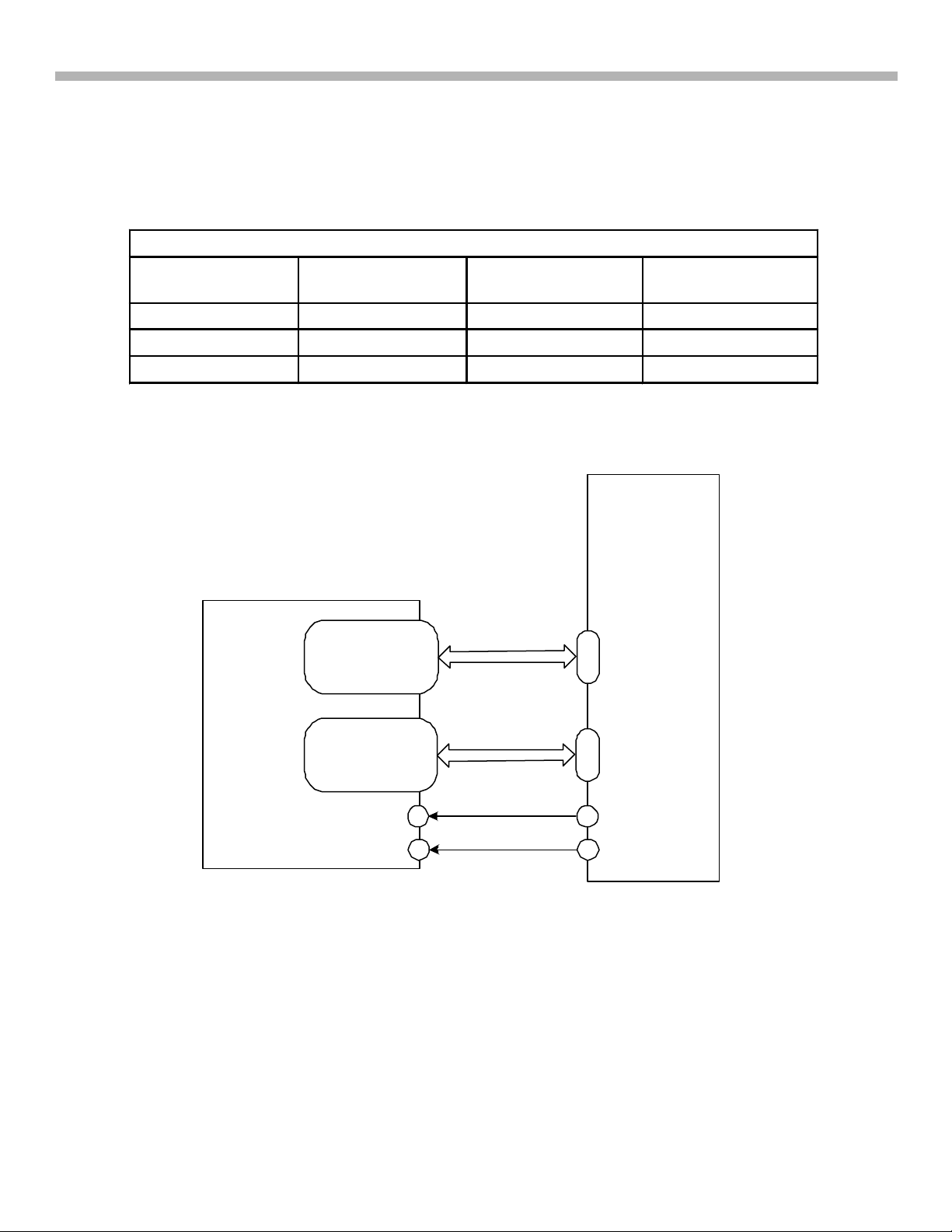
SRAM Control Lines
Number
D0 - D3 7 - 10
D4 - D7 13 - 16
D8 - D11 20 - 32
D12 - D15 35 - 38
Frequency Amplitude
53
|
69
IC1401
AUDIO
DSP
IC1402
SRAM
A0 - A4 5 - 1
A5 - A7 44 - 42
A8 - A11 27 - 24
A12 - A15 21 - 18
17
WE
41
OE
FIGURE 4-3 - SRAM BLOCK
53
69
74
70
|
XWE
XOE
9/26/01
There are 16 Data, 16 Address and two control lines (WE and OE) for the SRAM IC1402.. The SRAM is mainly
used for the processing of the Cinema and Hall sound fields where reverberation (Delay) is required to produce
the appropriate characteristics of a particular venue. The SRAM IC1402 is not used in any of the Virtual Speaker
Modes. All processing is performed by internal RAM in IC1401, so no data is present on either the Data, WE or
OE lines. Waveforms 4-8, 4-9 and 4-10 show the activity on the Data lines. WE and OE lines are in three
different modes: AFD, 2CH and Mode (sound field selection mode). The main point of interest of these three
17
 Loading...