

Sony HBD-N590, HBD-N790W, HBD-T79, HBD-N890W, HBD-N990W Service Manual
...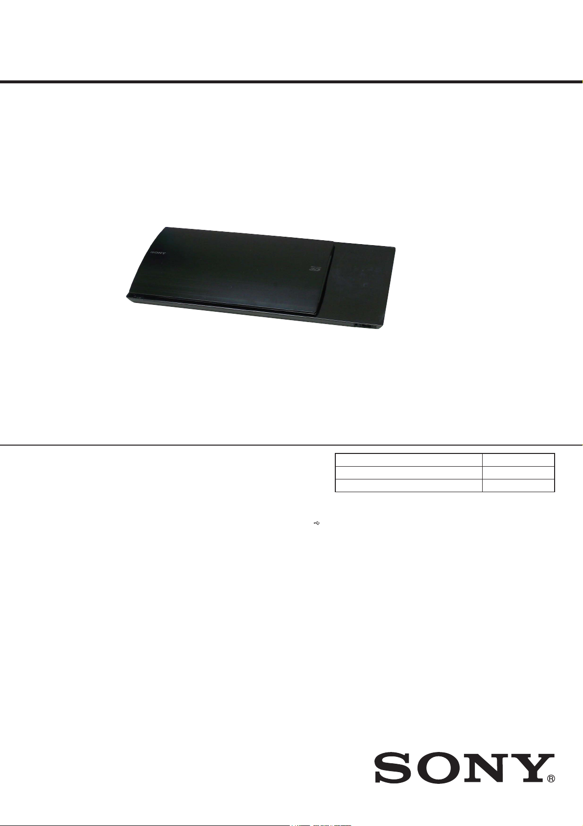
HBD-N590/N790W/N890W/
SERVICE MANUAL
Ver. 1.2 2012.06
Photo: HBD-N990W
N990W/N995W/T79
US Model
HBD-N790W/N890W/T79
Canadian Model
Russian Model
Saudi Arabia Model
Iranian Model
Taiwan Model
Middle East Model
HBD-N890W/N990W
AEP Model
HBD-N590/N790W/N890W/N990W
UK Model
HBD-N590/N790W
Australian Model
HBD-N590/N990W
Chinese Model
HBD-N995W
PX Model
HBD-N790W
• HBD-N590 is the Blu-ray discTM/DVD receiver in BDV-N590.
• HBD-N790W is the Blu-ray discTM/DVD receiver in BDV-N790W.
• HBD-N890W is the Blu-ray discTM/DVD receiver in BDV-N890W.
• HBD-N990W is the Blu-ray discTM/DVD receiver in BDV-N990W.
• HBD-N995W is the Blu-ray disc
• HBD-T79 is the Blu-ray disc
TM
/DVD receiver in BDV-N995W.
TM
/DVD receiver in BDV-T79.
• In order to perform the operation checking, all the units contained in this unit are needed.
Model Name Using Similar Mechanism NEW
Mechanism Type BSX-3
Optical Pick-up Name KEM-480AAA
SPECIFICATIONS
HDMI
Amplifier Section
HBD-N790W/N890W/N990W/N995W/T79
U.S.models:
AUDIO POWER SPECIFICATIONS
POWER OUTPUT AND TOTAL HARMONIC
DISTORTION:
(FTC)
Front L + Front R: With 3 ohms loads, both
Except US and Chinese models:
POWER OUTPUT (rated)
Front L/Front R: 78 W + 78 W (at 3 ohms, 1
POWER OUTPUT (reference) (Except Chinese model)
Front L/Front R: 125 W (per channel at
Center: 250 W (at 6 ohms, 1 kHz)
Subwoofer: 250 W (at 6 ohms, 80 Hz)
POWER OUTPUT (reference) (Chinese model)
Front L/Front R: 75 W (per channel at
Center: 150 W (at 6 ohms, 1 kHz)
Subwoofer: 150 W (at 6 ohms, 80 Hz)
Inputs (Analog)
AUDIO (AUDIO IN) Sensitivity: 3.0 V/1.0 V
Inputs (Digital)
TV (Audio Return Channel/OPTICAL)
channels driven, from 180
Hz - 20 kHz; rated 50 watts
per channel minimum
RMS power, with no more
than 1% total harmonic
distortion from 250 milli
watts to rated output.
kHz, 1% THD)
3 ohms, 1 kHz)
3 ohms, 1 kHz)
Supported formats: LPCM
2CH (up to 48 kHz), Dolby
Digital, DTS
(IN 1)/HDMI (IN 2)
HBD-N590
POWER OUTPUT (rated)
Front L/Front R: 78 W + 78 W (at 3 ohms,
POWER OUTPUT (reference)
Front L/Front R/Surround L/Surround R:
Center: 250 W (at 6 ohms, 1 kHz)
Subwoofer: 250 W (at 6 ohms, 80 Hz)
Inputs (Analog)
AUDIO (AUDIO IN) Sensitivity: 3.0 V/1.0 V
Inputs (Digital)
TV (Audio Return Channel/OPTICAL)
HDMI (IN 1)/HDMI (IN 2)
Video Section
Outputs VIDEO: 1 Vp-p 75 ohms
HDMI Section
Connector Type A (19pin)
BD/DVD/Super Audio CD/CD System
Signal format system US, Canadian and PX models:
Supported formats: LPCM
5.1CH (up to 48 kHz),
LPCM 2CH (up to
96 kHz), Dolby Digital,
DTS
1kHz, 1% THD)
125 W (per channel at
3ohms, 1 kHz)
Supported formats: LPCM
2CH (
up to 48 kHz), Dolby
Digital, DTS
Supported formats: LPCM
5.1CH (up to 48 kHz),
LPCM 2CH (up to
96 kHz), Dolby Digital,
DTS
NTSC
AEP model: PAL
Other models: NTSC/PAL
USB Section
USB 1/2 port: Type A (For connecting
LAN Section
LAN (100) terminal 100BASE-TX Terminal
Wireless LAN Section
Standards Compliance IEEE 802.11 b/g/n
Frequency and Channel 2.4 GHz - 2.4835 GHz
FM Tuner Section
System PLL quartz-locked digital
Tuning range 87.5 MHz - 108.0 MHz
Antenna (aerial) FM wire antenna (aer ial)
Antenna (aerial) terminals 75 ohms, unbalanced
USB memory, memor y
card reader, digital still
camera, and digital video
camera)
[CH1 -11]
(US and Canadian models)
[CH1 -13]
(Except US and Canadian models)
synthesizer
(50 kHz step)
(Except US, Canadian and PX
models)
87.5 MHz - 108.0 MHz
(100 kHz step)
(US, Canadian and PX models)
BLU-RAY DISCTM/DVD RECEIVER
Mexican Model
Thai Model
Indian Model
HBD-N990W
Singapore Model
HBD-N590/N890W/N990W
General
Power requirements 120 V AC, 60 Hz
Power consumption
HBD-N995W On: 110 W
HBD-N790W/N890W/N990W/T79
HBD-N590 On: 135 W
(US and Canadian models)
120 V AC, 50/60 Hz
(Taiwan model)
110 V - 240 V AC,
50/60 Hz (Mexican and PX models)
220 V - 240 V AC,
50/60 Hz
(Except US, Canadian, Mexican,
Taiwan and PX models)
Standby: 0.3 W (at the
Power Saving mode)
On: 115 W
Standby: 0.3 W (at the
Power Saving mode)
Standby: 0.3 W (at the
Power Saving mode)
– Continued on next page –
9-893-438-03
2012F33-1
2012.06
©
Sony Corporation
Published by Sony Techno Create Corporation
HBD-N590/N790W/N890W/N990W/N995W/T79
Ver. 1.1
Dimensions (approx.)
HBD-N790W/N890W/N990W/N995W/T79
HBD-N590 460 mm × 74 mm ×
Mass (approx.)
HBD-N995W
HBD-N790W/N890W/N990W/T79
HBD-N590 3.5 kg
Design and specifications are subject to change
without notice.
HBD-N790W/N890W/N990W/N995W/T79
Standby power consumption 0.3W (Main Unit),
0.2W (Surround Amplifier).
Over 85% power efficienc
achieved with the full digita l amplifier, S-Master.
HBD-N590
Standby power consumption 0.3W.
Over 85% power efficiency of amplifier block is
achieved with the full digita l amplifier, S-Master.
460 mm × 74 mm ×
226 mm (w/h/d) incl.
projecting parts
460 mm × 74 mm ×
239 mm (w/h/d) (with the
wireless transceiver
inserted)
460 mm × 148 mm ×
226 mm (w/h/d) (with
stand and cord cover
attached) (HBD-N990W/
N995W only)
226 mm (w/h/d) incl.
projecting parts
3.7 kg
3.6 kg
y of amplifier block is
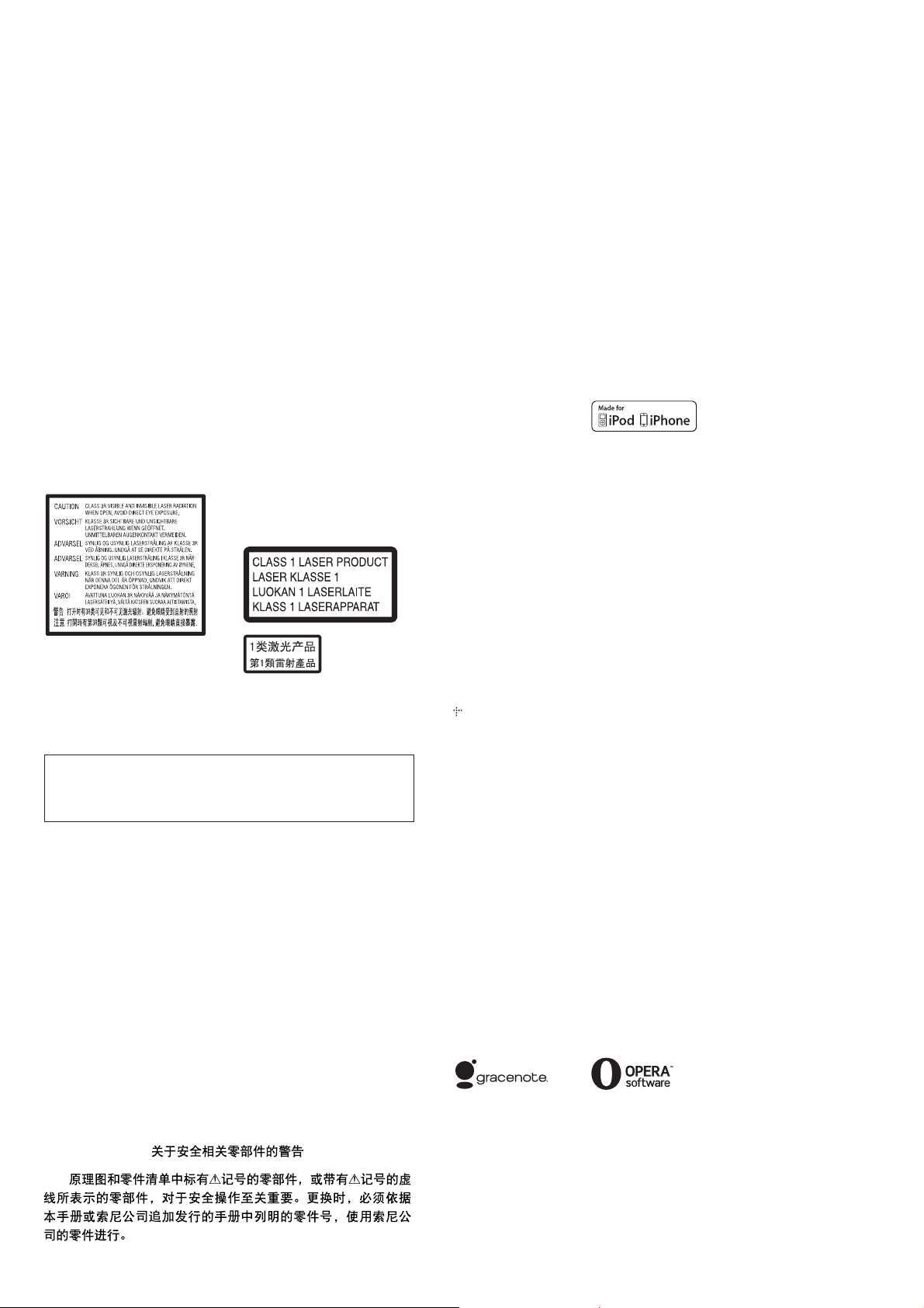
This marking is located on the laser
protective housing inside the
enclosure.
This appliance is classified as a
CLASS 3R LASER product.
Visible and invisible laser radiation
is emitted when the laser protective
housing is opened, so be sure to
avoid direct eye exposure.
This appliance is classified as a
CLASS 1 LASER product. This
marking is located on the rear
exterior.
CAUTION
Use of controls or adjustments or performance of procedures
other than those specifi ed herein may result in hazardous radia-
tion exposure.
SAFETY-RELATED COMPONENT WARNING!
COMPONENTS IDENTIFIED BY MARK 0 OR DOTTED LINE
WITH MARK 0 ON THE SCHEMATIC DIAGRAMS AND IN
THE PARTS LIST ARE CRITICAL TO SAFE OPERATION.
REPLACE THESE COMPONENTS WITH SONY PARTS
WHOSE PART NUMBERS APPEAR AS SHOWN IN THIS
MANUAL OR IN SUPPLEMENTS PUBLISHED BY SONY.
ATTENTION AU COMPOSANT AYANT RAPPORT
À LA SÉCURITÉ!
LES COMPOSANTS IDENTIFIÉS PAR UNE MARQUE 0 SUR
LES DIAGRAMMES SCHÉMATIQUES ET LA LISTE DES
PIÈCES SONT CRITIQUES POUR LA SÉCURITÉ DE FONCTIONNEMENT. NE REMPLACER CES COMPOSANTS QUE
PAR DES PIÈCES SONY DONT LES NUMÉROS SONT DONNÉS DANS CE MANUEL OU DANS LES SUPPLÉMENTS
PUBLIÉS PAR SONY.
Copyrights and
Trademarks
This system incorporates with
Dolby* Digital and Dolby Pro
Logic adaptive matrix surround
decoder and the DTS** Digital
Surround System.
* Manufa ctured under license
from Dolby Laboratories.
Dolby, Pro Logic, and the
double-D symbol are
trademarks of Dolby
Laboratories.
** Manufactured under license
under U.S. Patent Nos:
5,956,674; 5,974,380;
6,226,616; 6,487,535;
7,212,872; 7,333,929;
7,392,195; 7,272,567 &
other U.S. and worldwide
patents issued & pending.
DTS-HD, the Symbol, &
DTS-HD and the Symbol
together are registered
trademarks of DTS, Inc.
Product includes software.
© DTS, Inc. All Rights
Reserved.
This system incorporates High-
Definition Multimedia Interface
TM
(HDMI
) technology.
HDMI, the HDMI logo and HighDefinition Multimedia Interface
are trademarks or registered
trademarks of HDMI Licensing
LLC in the United States and
other countries.
J
ava is a tradem ark of Oracle and/
or its affiliates.
“BD-LIVE” and
“BONUSVIEW” are trademarks
of Blu-ray Disc Association.
“Blu-ray Disc” is a trademark.
“Blu-ray Disc,” “DVD+RW,”
“DVD-RW,” “DVD+R,” “DVDR,” “DVD VIDEO,” and “CD”
logos are trademarks.
“Blu-ray 3D” and “Blu-ray 3D”
logo are trademarks of Blu-ray
Disc Association.
“BRAVIA” is a trademark of
Sony Corporation.
“AVCHD” and the “AVCHD”
logo are trademarks of Panasonic
Corporation and Sony
Corporation.
, “XMB,” and “xross media
bar” are tradem
Corporation and Sony Computer
Entertainment Inc.
“PlayStation” is a registered
trademark of Sony Computer
Entertainment Inc.
Music and video recognition
technology and related data are
provided by Gracenote
Gracenote is the industry standard
in music recognition technology
and related content delivery. For
more information, please visit
www.gracenote.com.
CD, DVD, Blu-ray Disc, and
music and video-related data from
Gracenote, Inc., copyright ©
2000-present Grac
Gracenote Software, copyright ©
2000-present Gracenote. One or
more patents owned by Gracenote
apply to this product and service.
See the Gracenote website for a
nonexhaustive list of applicable
Gracenote patents. Gracenote,
CDDB, MusicID, MediaVOCS,
the Gracenote logo and logotype,
and the “Powered by Gracenote”
logo are either registered
trademarks or trademarks of
Gracenote in the United States
and/or other countries.
Wi-Fi
and Wi-Fi Alliance
registered marks of the Wi-Fi
Alliance.
Wi-Fi CERTIFIED™, WPA™,
WPA2™ and Wi-Fi Protected
Setup™ are marks of the Wi-Fi
Alliance.
The Wi-Fi CERTIFIED Logo is a
certification mark of the Wi-Fi
Alliance.
The Wi-Fi Protected Setup M ark
is a mark of the Wi-Fi Alliance
arks of Sony
®
.
enote.
®
, Wi-Fi Protected Access®
®
are
“PhotoTV HD” an d the “PhotoTV
HD” logo are trademarks of Sony
Corporation.
MPEG Layer-3 audio coding
technology and patents licensed
from Fraunhofer IIS and
Thomson.
This product inco
proprietary technology under
license from Verance Corporation
and is protected by U.S. Patent
7,369,677 and other U.S. and
worldwide patents issued and
pending as well as copyright and
trade secret protection for certain
aspects of such technology.
Cinavia is a trademark of Verance
Corporation. Copyright 20042010 Verance Corporation. All
rights reserved by Verance.
Reverse engineering or
disassembly is prohibited.
iPhone, iPod, iPod classic, iPod
nano, and iPod touc
trademarks of Apple Inc.,
registered in the U.S. and other
countries.
“Made for iPod,” and “Made for
iPhone” mean that an electronic
accessory has been designed to
connect specifically to iPod or
iPhone, respectively, and h as been
certified by the developer to meet
Apple performance standards.
Apple is not responsible for the
operation of this device or its
compliance with safety and
regulatory standards. Please
that the use of this accessory with
iPod or iPhone may affect
wireless performance.
Windows Media is either a
registered trademark or trademark
of Microsoft Corporation in the
United States and/or other
countries.
This product contains technology
subject to certain intellec tual
property rights of Microsoft. Use
or distribution of this technology
outside of this product is
prohibited without the appropriate
license(s) from Micr osoft.
Content owners us
PlayReady
technology to protect their
intellectual property, including
copyrighted content. This device
uses PlayReady technology to
access PlayReady-protected
content and/or WMDRMprotected content. If the device
fails to properly enforce
restrictions on content usage,
content owners may require
Microsoft to revoke the device’s
ability to consume PlayReadyprotected content. Revocation
should not affect unprotecte d
content or cont
other content access technologies.
Content owners may require you
to upgrade PlayReady to a ccess
their conten t. If you decline an
upgrade, you will not be abl e to
access content that requires the
upgrade.
DLNA
DLNA CERTIFIED
trademarks, service marks, or
certification marks of the Digital
Living Network Alliance.
Opera
Software ASA. Copyright 19952010 Opera Software ASA. All
rights reserved.
All other trademarks are
trademarks of their respective
owners.
Other system and product names
are generally trademarks or
registered trademarks of the
manufacturers. ™ and ® marks
are not indicated in this documen t.
rporates
h are
e Microsoft
™
content access
ent protected by
®
, the DLNA Logo and
™
are
®
Browser from Opera
note
®
2

HBD-N590/N790W/N890W/N990W/N995W/T79
TABLE OF CONTENTS
Ver. 1.1
1. SERVICING NOTES ............................................. 4
2. DISASSEMBLY
2-1. Disassembly Flow ........................................................... 12
2-2. Cover (Top) Block .......................................................... 13
2-3. TOUCH Board ................................................................ 14
2-4. Cover (Bottom) Block .................................................... 15
2-5. Shield (Drive) ................................................................. 16
2-6. BD Drive (BSX-3) .......................................................... 16
2-7. LED Board ...................................................................... 17
2-8. Wireless LAN Card (WLC1) (Except N995W) .............. 17
2-9. Chassis (Middle) Block .................................................. 18
2-10. Bracket (Drive) ............................................................... 18
2-11. WS Board Block (Except N590) .................................... 19
2-12. Shield (PS) Block ............................................................ 19
2-13. Switching Regulator (SWR1) ......................................... 20
2-14. Bracket (PS) .................................................................... 21
2-15. Power Cord (AC1) .......................................................... 21
2-16. Heat Sink (AMP) ............................................................ 22
2-17. NX_AMP Board ............................................................. 22
2-18. MB-149 Board ................................................................ 23
2-19. Bottom Cover .................................................................. 24
2-20. Optical Pick-up (KEM-480AAA) ................................... 25
2-21. How To Bend Wire (Flat Type) ....................................... 26
3. TEST MODE ............................................................ 27
4. ELECTRICAL CHECK ......................................... 36
5. DIAGRAMS
5-1. Block Diagram - SERVO Section - ................................ 37
5-2. Block Diagram - MEMORY Section - ............................ 38
5-3. Block Diagram - MAIN Section - ................................... 39
5-4. Block Diagram - AMP Section - ..................................... 40
5-5. Block Diagram - POWER SUPPLY Section - ................ 41
5-6. Schematic Diagram - MB-149 Board (1/11) - ................ 43
5-7. Schematic Diagram - MB-149 Board (2/11) - ................ 44
5-8. Schematic Diagram - MB-149 Board (3/11) - ................ 45
5-9. Schematic Diagram - MB-149 Board (4/11) - ................ 46
5-10. Schematic Diagram - MB-149 Board (5/11) - ................ 47
5-11. Schematic Diagram - MB-149 Board (6/11) - ................ 48
5-12. Schematic Diagram - MB-149 Board (7/11) - ................ 49
5-13. Schematic Diagram - MB-149 Board (8/11) - ................ 50
5-14. Schematic Diagram - MB-149 Board (9/11) - ................ 51
5-15. Schematic Diagram - MB-149 Board (10/11) - .............. 52
5-16. Schematic Diagram - MB-149 Board (11/11) - .............. 53
5-17. Printed Wiring Board - MB-149 Board (Side A) - .......... 54
5-18. Printed Wiring Board - MB-149 Board (Side B) - .......... 55
5-19. Printed Wiring Board - FL Board - ................................. 56
5-20. Schematic Diagram - FL Board - .................................... 57
5-21. Printed Wiring Boards - PANEL Section - ..................... 58
5-22. Schematic Diagram - PANEL Section - .......................... 59
5-23. Printed Wiring Board
- NX_AMP Board (Component Side) - .......................... 60
5-24. Printed Wiring Board
- NX_AMP Board (Conductor Side) - ............................ 61
5-25. Schematic Diagram - NX_AMP Board - ........................ 62
6. EXPLODED VIEWS
6-1. Cover (Bottom) Section .................................................. 82
6-2. Cover (Top) Section ........................................................ 83
6-3. LED Board Section ......................................................... 84
6-4. BD Drive Section (BSX-3) ............................................. 85
6-5. FL Board Section ............................................................ 86
6-6. Switching Regulator Section .......................................... 87
6-7. NX_AMP Board Section ................................................ 88
6-8. MB-149 Board Section ................................................... 89
7. ELECTRICAL PARTS LIST .............................. 90
3
HBD-N590/N790W/N890W/N990W/N995W/T79
SECTION 1
SERVICING NOTES
NOTES ON HANDLING THE OPTICAL PICK-UP
BLOCK OR BASE UNIT
The laser diode in the optical pick-up block may suffer electrostatic break-down because of the potential difference generated by
the charged electrostatic load, etc. on clothing and the human body.
During repair, pay attention to electrostatic break-down and also
use the procedure in the printed matter which is included in the
repair parts.
The fl exible board is easily damaged and should be handled with
care.
NOTES ON LASER DIODE EMISSION CHECK
The laser beam on this model is concentrated so as to be focused
on the disc refl ective surface by the objective lens in the optical
pickup block. Therefore, when checking the laser diode emission,
observe from more than 30 cm away from the objective lens.
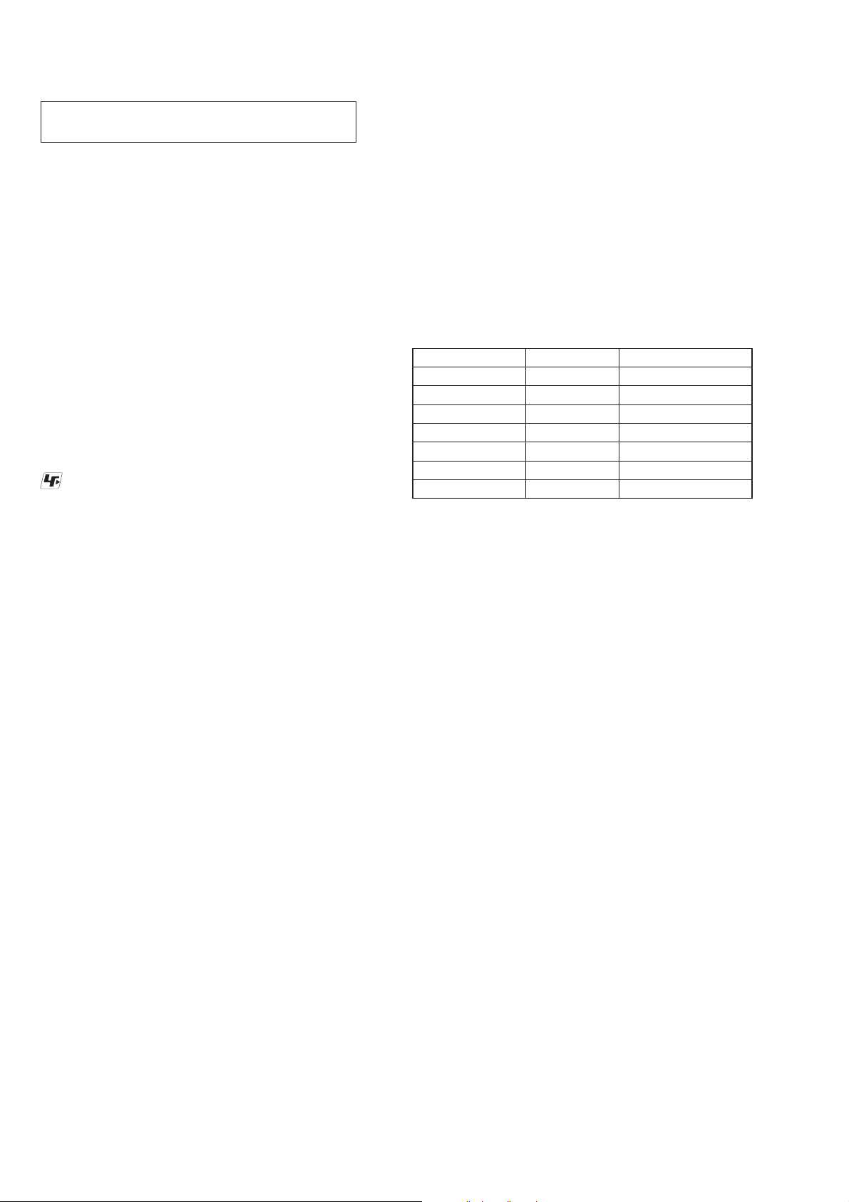
UNLEADED SOLDER
Boards requiring use of unleaded solder are printed with the leadfree mark (LF) indicating the solder contains no lead.
(Caution: Some printed circuit boards may not come printed with
the lead free mark due to their particular size)
: LEAD FREE MARK
Unleaded solder has the following characteristics.
• Unleaded solder melts at a temperature about 40 °C higher
than ordinary solder.
Ordinary soldering irons can be used but the iron tip has to be
applied to the solder joint for a slightly longer time.
Soldering irons using a temperature regulator should be set to
about 350 °C.
Caution: The printed pattern (copper foil) may peel away if
the heated tip is applied for too long, so be careful!
• Strong viscosity
Unleaded solder is more viscous (sticky, less prone to fl ow)
than ordinary solder so use caution not to let solder bridges
occur such as on IC pins, etc.
• Usable with ordinary solder
It is best to use only unleaded solder but unleaded solder may
also be added to ordinary solder.
RELEASING THE DISC SLOT LOCK
The disc slot lock function for the antitheft of an demonstration
disc in the store is equipped.
Releasing Procedure:
1. Press the [
2. Press the [HOME] button on the remote commander to enter
the home menu.
3. Touch the [x] and [Z] sensors simultaneously and hold down
unit “DEMO OFF” displayed on the fluorescent indicator tube
(around 5 seconds).
Note: When “DEMO.LOCK” is displayed, the disc slot lock is not re-
leased by turning power on/off with the [
ABOUT THE LENS CLEANING
Do not do the lens cleaning with the cotton bud etc. It causes the
trouble.
] button to turn on the system.
?/1
?/1
] button.
NOTE OF REPLACING THE IC101 AND IC501 ON
THE MB-149 BOARD
IC101 and IC501 on the MB-149 board cannot exchange with
single. When these parts are damaged, exchange the complete
mounted board.
NOTE OF REPLACING THE IC102, IC103, IC202 AND
IC203 ON THE MB-149 BOARD
Replacement of IC102, IC103, IC202 and IC203 on the MB-149
board used in this unit requires a special tool.
NOTE OF REPLACING THE TOUCH BOARD
When the TOUCH board is defective, exchange the complete
mounted board.
TEST DISC
Part No. Description Layer
J-6090-199-A BLX-104 Single Layer
J-6090-200-A BLX-204 Dual Layer
J-2501-307-A CD (HLX-A1)
J-2501-305-A HLX-513 Single Layer (NTSC)
J-2501-306-A HLX-514 Dual Layer (NTSC)
J-6090-077-A HLX-506 Single Layer (PAL)
J-6090-078-A HLX-507 Dual Layer (PAL)
Note: Refer to the service manual of BDP-BX1/S350 (Part No. 9-883-
989-1[]) (page 1-3 to 1-14E) for the use of BLX-104/204.
Operation and Display:
1. BLX-104
Procedure:
1. Select 23.976Hz/1080p.
2. Play “4.Motion picture”.
3. Check whether player can play back or not.
4. Check each outputs.
Video:
Composite/HDMI.
Audio:
Speaker out.
* When 1080/24p monitor is nothing, 1080i (59.94Hz or 50Hz)
can use instead of 1080/24p.
However this is temporary correspondence.
* When the output of HDMI is 1080p/1080i/720p, the signal of
composite is not output.
It is necessary to lower the output of HDMI to 480p or 576p or
less.
2. BLX-204
Procedure:
1. Select 1080i (59.94Hz or 50Hz).
2. Play “4.Motion picture”.
3. Check whether player can play back or not (Check the picture
and sound output).
3. CD (HLX-A1)
Procedure:
Check whether player can play back or not (Check the sound output).
4. HLX-513/514 (NTSC), HLX-506/507 (PAL)
Procedure:
1. After displayed Main Menu, select “1.Video Signal”.
2. Play “1.Color bar 100%” (Check the picture and sound out-
put).
3. Return to Menu.
4. Play “Demonstration 4:3” or “Demonstration 16:9” (Check the
picture and sound output).
4

HBD-N590/N790W/N890W/N990W/N995W/T79
NOTE OF REPLACING THE OPTICAL DEVICE (KEM480AAA) OR MB-149 BOARD
The password will be supplied to only service HQ, and
service center name, q’ty and all of software registered
information should be maintained by service HQ, and
Audio will ask to report the registration information.
Optical device (KEM-480AAA) for BD requires precise read out
functions and secure contents protection system for more than past
DVD/CD.
Therefore, in the case repaired as follows, the writing work of the
OP data is necessary.
• When the optical device (KEM-480AAA) is replaced (The
MB-149 board doesn’t replace).
• When both the optical device (KEM-480AAA) and MB-149
board are replaced.
• When the MB-149 board is replaced (The optical device
(KEM-480AAA) doesn’t replace) (In this case, do the work of
“3. Optical device (KEM-480AAA) replacement” other than
the replacement of new optical device).
Note: The servo adjustment is done while writing the OP data. The manual
adjustment is unnecessary.
LD ON TIME history doesn’t carry over.
Do not touch any optical block parts, turn table and during replac-
ing. BD laser diode is very sensitive.
1. Preparation
1-1. ESD Countermeasure
It is necessary to confi rm the state of static electricity in the work
space before the repair is started.
The static electricity resistance of the BD laser is weaker than that
of the DVD/CD laser.
Do work space and worker’s ESD countermeasures to prevent destruction by ESD.
1-2. Jig
• Digital camera (Recommend with macro mode)
• USB memory
• PC
• Barcode decoder (Refer to “1-3. Barcode decoder
(BDPRdec)”)
1-3. Barcode decoder (BDPRdec)
Jig name: BDPRdec.exe
Software contents:
• BDPRdec.exe : Barcode decoder software
• SavePath.ini : Decoded fi le destination setting fi le (Ini-
tial destination is “C:\BuData.txt”)
• TasmanBars.dll : Decode dll
• Uninst.exe : Uninstall the “BDPRdec.exe” from PC
Note: When working by OS of the version after VISTA, it is necessary
to change destination of the decoded fi le to save by UAC function
(user account function).
In that case, change the description in “SavePath.ini” (default de-
scription is “C:\BuData.txt”) other than C drive.
Install procedure:
1. Unzip the barcode decoder fi les to any PC folder.
2. Check the attached 2D code photo (OK_sample.JPG) drag &
drop onto “BDBUDec.exe”.
When the barcode decoder is used for the fi rst time, the pass-
word is necessary. It is unnecessary since the second times.
Note 1: The password will be supplied to only service headquarters, and
service center name/q’ty/all of software registered information
should be maintained by service headquarters.
Note 2: Do not change the decoded fi le name “BuData.txt”.
3. When “.NET frame work requirements” is displayed, down-
load following applications from Microsoft download site.
• Microsoft .NET Framework Version 2.0 Redistributable Pack-
age (x86)
http://www.microsoft.com/downloads/details.aspx?displaylan
g=en&FamilyID=0856eacb-4362-4b0d-8edd-aab15c5e04f5
• Microsoft .NET Framework 2.0 Service Pack 1 (x86)
http://www.microsoft.com/downloads/details.aspx?displaylan
g=en&FamilyID=79bc3b77-e02c-4ad3-aacf-a7633f706ba5
How to use:
Case 1 Drag & drop 2D code photo onto “BDPRdec.exe”.
Case 2 Drag & drop BU data fi le onto “BDPRdec.exe”.
Data fi le name be changed to specify format and end of
7 character are defi ned.
You can also enter the fi le path at the prompt.
5
HBD-N590/N790W/N890W/N990W/N995W/T79
2. Pass-fail judgment of the optical device (KEM-480AAA)
Perform pass-fail judgment to judge whether the repair of the optical device (KEM-480AAA) is necessary.
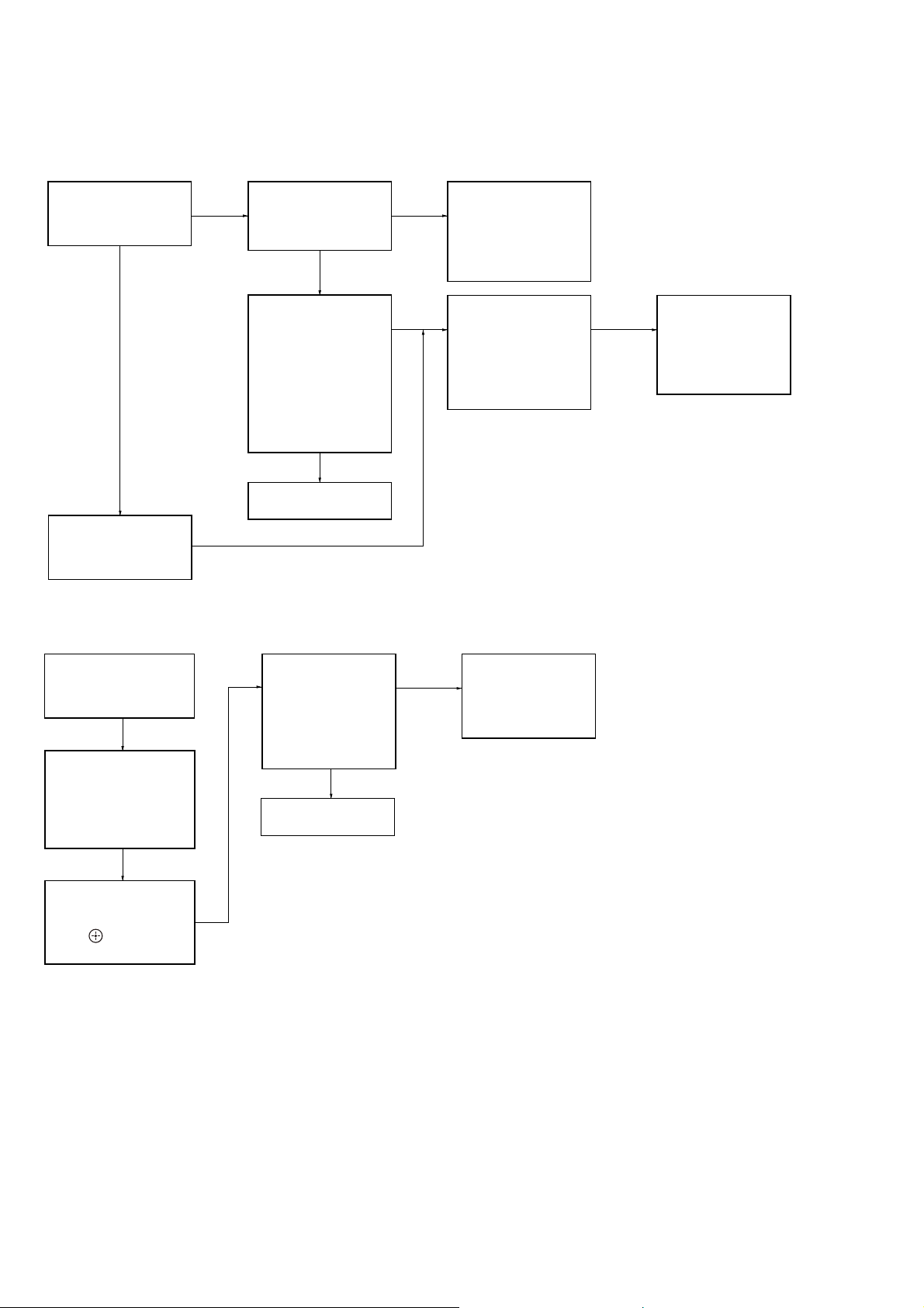
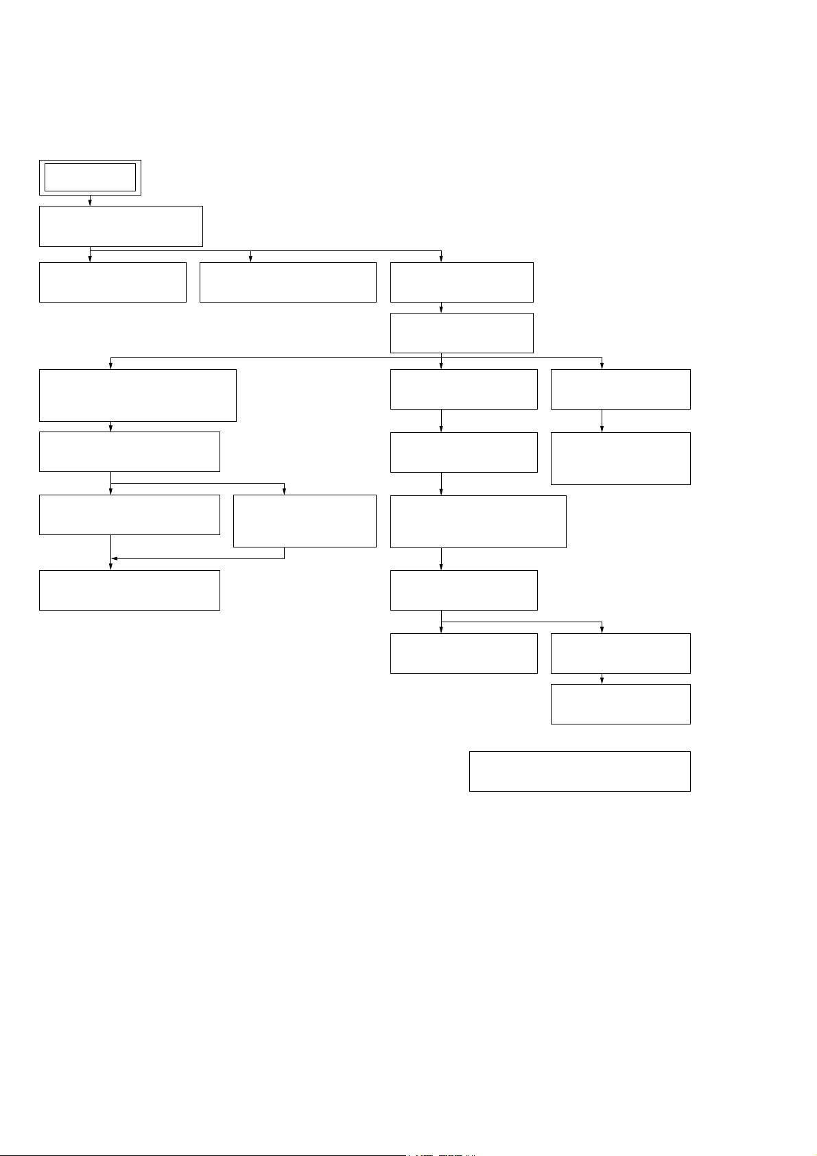
2-1. Flow of drive section check
Confirm whether
BD (BLX-104) can be
reproduced
YES
NO
Confirm whether the
drive voltage is the
CN5301 pin 3 : 12 V
NO
following values
YES
Confirm F5303,
F5305 to F5307
on the MB-149 board,
and replace it
when it has been
damaged
Confirm OP FFC cable
(Part No. 1-838-108-11)
and SPD FFC cable
(Part No. 1-828-312-51),
and replace it when it
has been damaged
Then, confirm whether
this unit operates
normally
YES
OK
Confirm whether
DVD (HLX-513)/
CD (HLX-A1) can be
reproduced
Note: Refer to “2-19. BOTTOM COVER” (page 24) about how to remove the BOTTOM COVER).
NO
NO NO
Confirm whether the
optical device IOP
is normal in the
service mode
(Refer to “2-2. Flow
of optical device
IOP check”)
2-2. Flow of optical device IOP check
Turn the power on,
and change function
to “BD/DVD”
Press the buttons on
the remote commander
in order of [DISPLAY],
[0], [2], [1] [SUBTITLE],
and enter the service
mode
Confirm whether
value is the
specification value
Specification value:
BD : ±3 mA
DVD/CD: ±3 mA
YES
OK
NO
Repalece the
optical device
(Refer to “3. Optical
device (KEM-480AAA)
replacement”)
Repalece the
optical device
(KEM-480AAA)
(Refer to “3. Optical
device (KEM-480AAA)
replacement”)
Press the buttons on
the remote commander
in order of [8], [7], [3],
[ ], and the
dIOP value is displayed
6
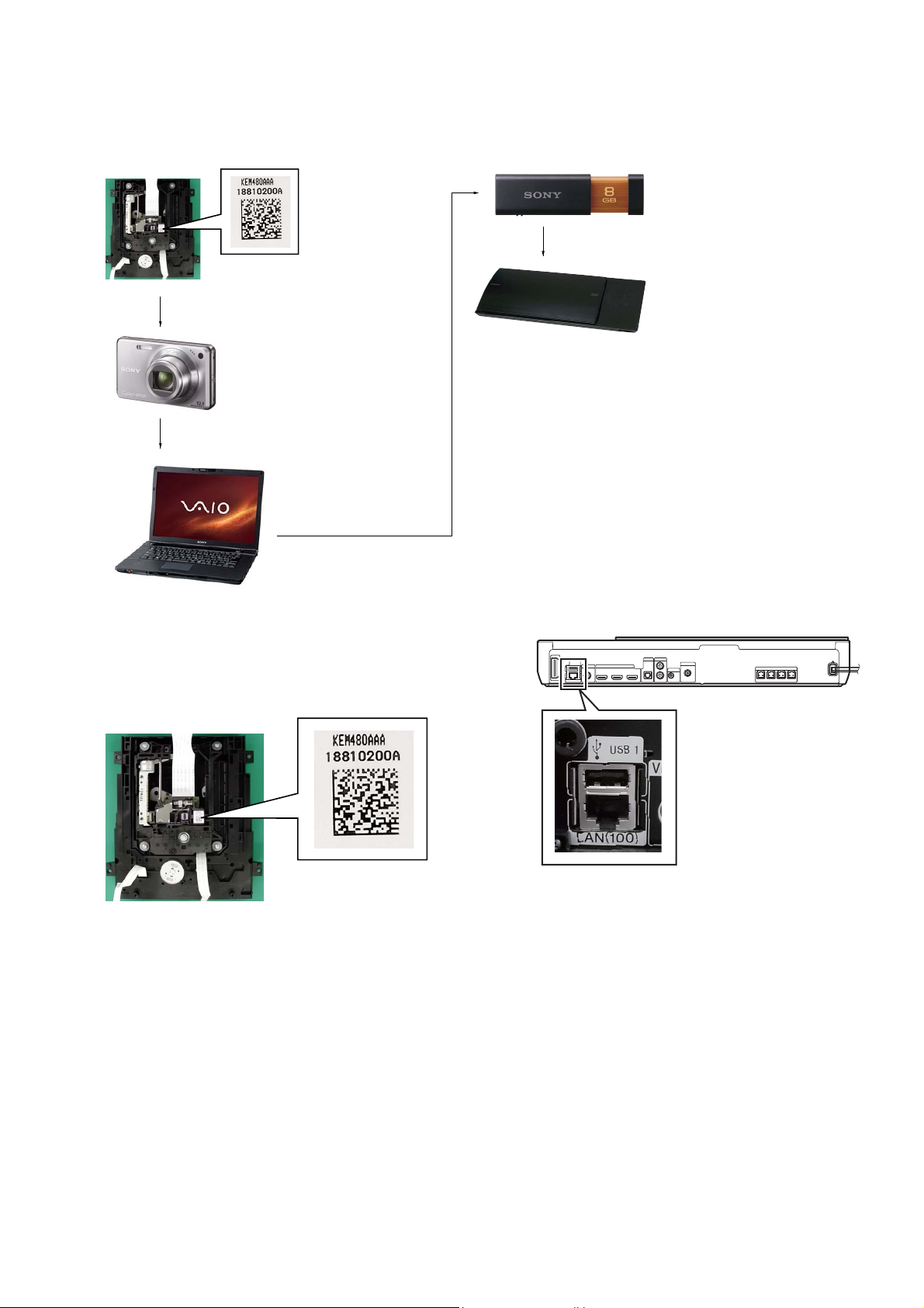
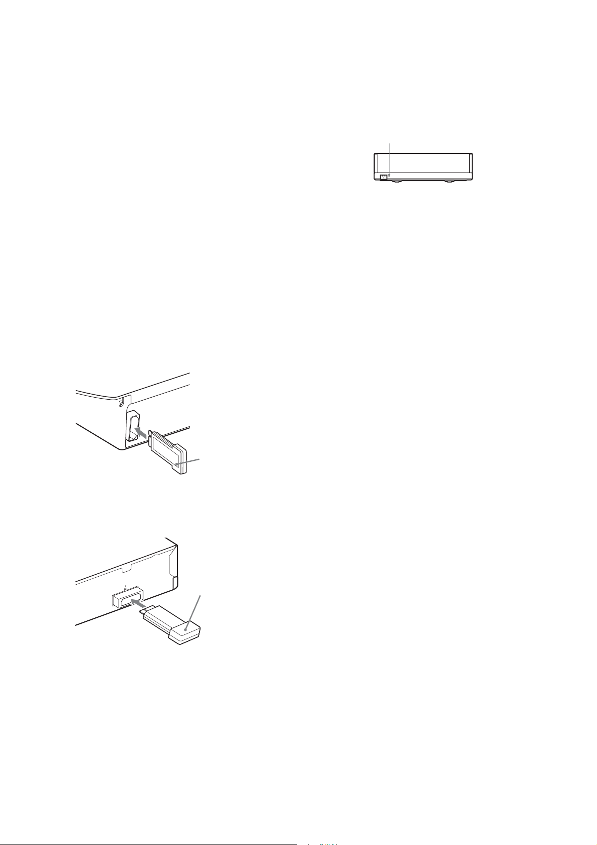
3. Optical device (KEM-480AAA) replacement
Flow of replacement:
Note: The photo in fl ow is an image.
Barcode label on
new optical device
(KEM-480AAA)
bottom side
Take photo (JPEG)
by digital camera
Change photo into
the text data with
the barcode decoder
HBD-N590/N790W/N890W/N990W/N995W/T79
Save the text data
to USB memory
(memory capacity
need not be 8GB)
Connect USB memory
with side USB connector
on this unit, and read the
text data by the service mode
Procedure:
1. Remove the INSULATOR (4 pieces) and broken optical device (KEM-480AAA) from LOADING ASSY.
2. Take photo of the barcode on new optical device (KEM480AAA) bottom side by digital camera.
3. Assemble the INSULATOR (4 pieces) to new optical device
(KEM-480AAA), fi x (Torque value: 2 kgf) it to LOADING
ASSY with screw, and assemble this unit.
4. Drag & drop the taken photo by step 2 to “BDPRDec.exe”, and
make the text data (File name: BuData.txt).
5. Save the text data to USB memory.
6. Connect USB memory with side USB connector on this unit,
and turn the power on.
– Rear view –
7. Press the [FUNCTION] button on the remote commander to
select “BD/DVD”.
8. Press the buttons on the remote commander in order of
[DISPLAY], [0], [2], [1], [SUBTITLE], and enter the service
mode.
9. Press the buttons on the remote commander in order of [8], [1],
[ENTER], and execute “[1] Drive OP data Write”.
10. Turn the power off after writing the OP data.
11. Turn the power on, and enter the service mode again.
12. Press the buttons on the remote commander in order of [8], [7],
[3], [ENTER], and the dIOP value is displayed.
13. Confi rm value is the following specifi cation value, and turn the
power off.
Specifi cation value:
BD : 3 mA
DVD/CD : 3 mA
14. Turn the power on, confi rm playback performance of the BD
(BLX-104)/DVD (HLX-513)/CD (HLX-A1).
15. Completely assemble this unit, and complete the repair.
7
HBD-N590/N790W/N890W/N990W/N995W/T79
Ver. 1.1
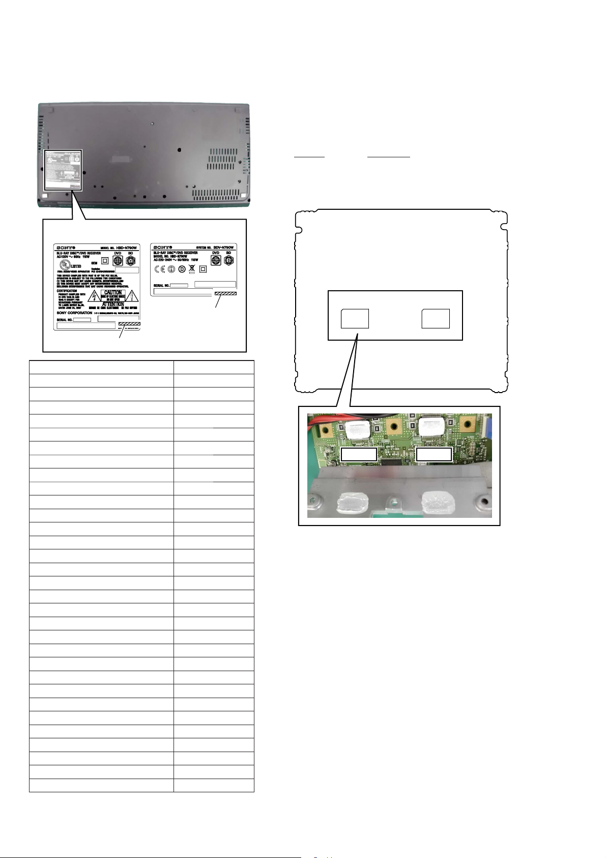
MODEL IDENTIFICATION
– Bottom side view –
The written example of model number label
Displayed characters/values are example.
Part No.
Model Part No.
HBD-N590: AEP
HBD-N590: UK
HBD-N790W: US
HBD-N790W: AEP
HBD-N790W: UK
HBD-N890W: US
HBD-N890W: AEP
HBD-N995W: CH
HBD-N990W: CND
HBD-N990W: AEP
HBD-N990W: RU
HBD-N990W: EA
HBD-N990W: MX
HBD-N590: SP
HBD-N590: AUS
HBD-T79: US
HBD-N890W: CND
HBD-N890W: E3
HBD-N890W: E15
HBD-N890W: EA
HBD-N890W: SP
HBD-N890W: TW
HBD-N990W: E12
HBD-N990W: E3
HBD-N990W: E15
HBD-N990W: SP
HBD-N990W: AUS
HBD-N990W: TH
HBD-N990W: TW
HBD-N790W: PX
HBD-N890W: RU
Part No.
4-409-290-0[]
4-409-290-1[]
4-409-291-0[]
4-409-292-0[]
4-409-292-1[]
4-409-293-0[]
4-409-294-0[]
4-409-295-0[]
4-409-296-0[]
4-409-297-0[]
4-409-298-0[]
4-409-299-0[]
4-409-300-0[]
4-417-413-0[]
4-417-414-0[]
4-417-415-0[]
4-417-418-0[]
4-417-419-0[]
4-417-420-0[]
4-417-421-0[]
4-417-422-0[]
4-417-424-0[]
4-417-425-0[]
4-417-426-0[]
4-417-427-0[]
4-417-428-0[]
4-417-429-0[]
4-417-430-0[]
4-417-431-0[]
4-422-025-0[]
4-429-510-0[]
NOTE OF REPLACING THE IC3102 AND IC3302 ON
THE NX_AMP BOARD AND THE COMPLETE NX_AMP
BOARD
When IC3102 and IC3302 on the NX_AMP board and the complete NX_AMP board are replaced, it is necessary to spread the
compound between parts and heat sink.
Part No. Description
J-2501-221-A THERMAL COMPOUND (G747)
Spread the compound referring to the fi gure below.
– NX_AMP Board (Component Side) –
IC3302
IC3302 IC3102
• Abbreviation
AUS : Australian model
CH : Chinese model
CND : Canadian model
E3 : Middle East model
E12 : Indian model
E15 : Iranian model
EA : Saudi Arabia model
MX : Mexican model
RU : Russian model
SP : Singapore model
TH : Thai model
TW : Taiwan model
IC3102
8

HBD-N590/N790W/N890W/N990W/N995W/T79
Ver. 1.1
ADVANCE PREPARATION WHEN CONFIRMING OPERATION
In order to perform the operation checking, all the units contained
in this unit are needed.
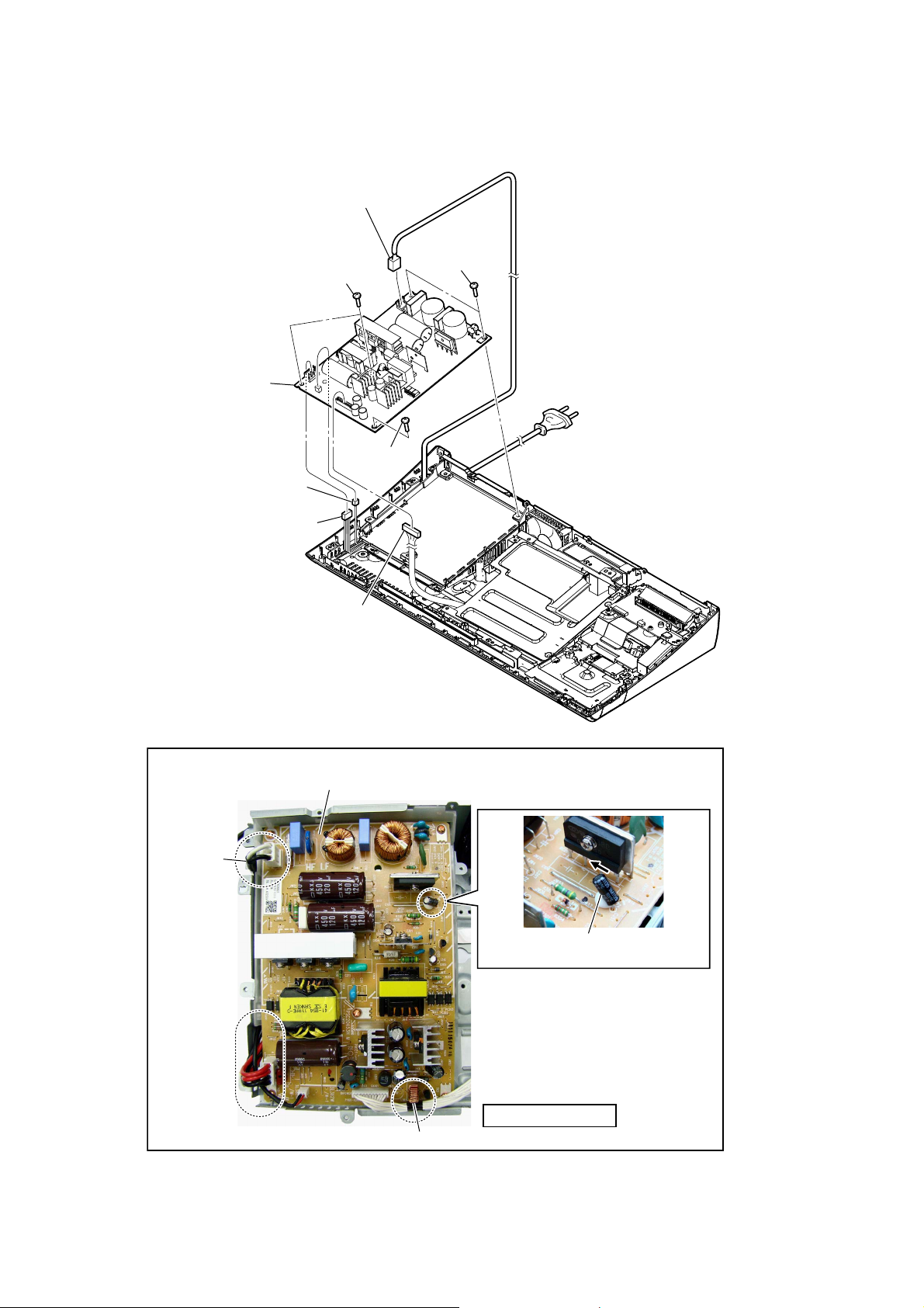
CAPACITOR ELECTRICAL DISCHARGE PROCESSING
When checking the board, the electrical discharge is necessary for
the electric shock prevention.
Connect the resistor to both ends of respective capacitors.
• Switching regulator
C207, C402
– SWITCHING REGULATOR (Component Side) –
C402
C207
C402
C207
CHECKING METHOD OF NETWORK OPERATION
(HBD-N590/N790W/N890W/N990W/T79 only)
It is necessary to check the network operation, when replacing the
MB-149 board or wireless LAN card (WLC1). Check the operation
of wireless and wired LAN, according to the following method.
1. Checking Method of Wireless LAN Operation
Check that access point is recognized surely.
Necessary Equipment:
Wireless access point with router function (AP)
Procedure:
1. Press the [HOME] button on the remote commander to enter
the home menu.
2. Press the [m]/[M]/[<]/[,] buttons on the remote commander to select “Setup”“Network Settings”, and press the [ ]
button on the remote commander.
3. Select “Internet Settings”, and press the [ ] button on the remote commander.
4. Press the [m]/[M] buttons on the remote commander to select
“Wireless Setup (built-in)”, and press the [ ] button on the
remote commander.
5. The system starts searching for access points, and displays a
list of up available network name (SSID).
6. Check that access point (SSID) is displayed on the searching
result.
7. Press the [
Note: Refer to the instruction manual about details of the setting method.
] button to turn the power off.
?/1
800 :/2 W
800 :/2 W
2. Checking method of wired LAN operation
Check that access point is recognized surely.
Procedure:
1. Connect the main unit to the router or the hub, etc. with the
LAN cable.
2. Press the [HOME] button on the remote commander to enter
the home menu.
3. Press the [m]/[M]/[<]/[,] buttons on the remote commander to select “Setup”“Network Settings”, and press the [ ]
button on the remote commander.
4. Select “Internet Settings”, and press the [ ] button on the remote commander.
5. Press the [m]/[M] buttons on the remote commander to select
“Wired Setup”, and press the [ ] button on the remote commander.
6. Press the [m]/[M] buttons on the remote commander to select
“Auto”, and press the [ ] button on the remote commander.
7. Press the [,] button on the remote commander.
8. Press the [m]/[M] buttons on the remote commander to select
“Save & Connect”, and press the [ ] button on the remote
commander.
9. When “Internet Settings is now complete.” appears, then press
the [ ] button on the remote commander.
10. Press the [HOME] button on the remote commander to enter
the home menu.
11. Press the [m]/[M]/[<]/[,] buttons on the remote commander to select “Setup”“Network Settings”, and press the [ ]
button on the remote commander.
12. Press the [m]/[M] buttons on the remote commander to select
“Network Connection Diagnostics”, and press the [ ] button
on the remote commander.
13. Press the [<]/[,] buttons on the remote commander to
select “Start”, and press the [ ] button on the remote commander.
14. Confi rm that “Network connections are correct” is displayed.
15. Press the [
Note: Refer to the instruction manual about details of the setting method.
] button to turn the power off.
?/1
9
HBD-N590/N790W/N890W/N990W/N995W/T79
Ver. 1.1
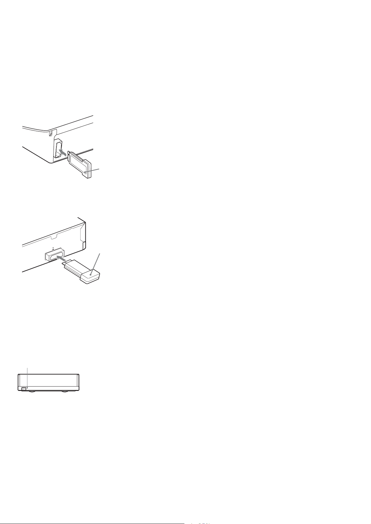
INSTALLATION METHOD OF THE WIRELESS SOUND
SYSTEM (HBD-N790W/N890W/N990W/N995W/T79 only)
Procedure:
1. Insert the wireless transceiver (EZW-RT50 (HBD-N790W/
N890W/N990W/T79) or EZW-RT20 (HBD-N995W)) of the
attachment in the wireless transceiver slot in the back of the
main unit (HBD-N790W/N890W/N990W/N995W/T79) and
the surround amplifi er (TA-SA300WR).
Rear panel of the main unit
(HBD-N790W/N890W/N990W/N995W/T79)
Wireless
transceiver
(EZW-RT50 (HBD-N790W/
N890W/N990W/T79) or
EZW-RT20 (HBD-N995W))
Rear panel of the surround amplifier
(TA-SA300WR)
W-RT50
EZ
Wireless
transceiver
(EZW-RT50 (HBD-N790W/
N890W/N990W/T79) or
EZW-RT20 (HBD-N995W))
2. Connect the AC power cord of the main unit (HBD-N790W/
N890W/N990W/N995W/T79).
3. Press the [
] button on the main unit (HBD-N790W/
\/1
N890W/N990W/N995W/T79).
4. Connect the AC power cord of the surround amplifi er (TA-
SA300WR).
5. When a wireless transceiving becomes effective, the [LINK/
STANDBY] indicator of surround amplifi er (TA-SA300WR)
lights to green.
Note: Refer to the operating instructions when the [LINK/STANDBY]
indicator of surround amplifi er (TA-SA300WR) doesn’t light.
LINK/STANDBY indicator
.+0-56#0&$;
10
HBD-N590/N790W/N890W/N990W/N995W/T79
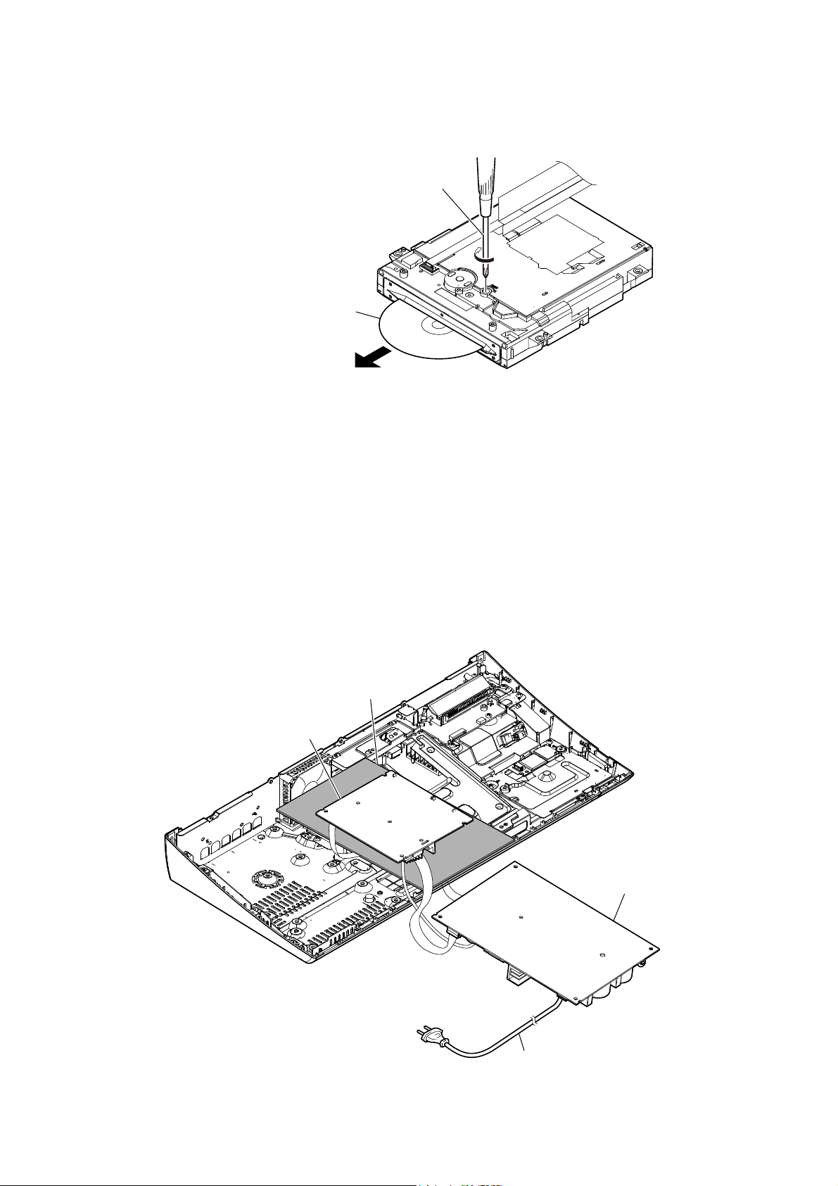
HOW TO EJECT THE DISC WHEN POWER SWITCH TURN OFF
The BD drive is taken out, and please rotate
the pulley in the direction of the arrow by
screwdriver etc. after detaching and take
out the disc.
disc
– BD drive bottom view –
NX_AMP BOARD SERVICE POSITION
insulating sheet
NX_AMP board
switching regulator (SWR1)
power cord
11
HBD-N590/N790W/N890W/N990W/N995W/T79
Ver. 1.1
SECTION 2
DISASSEMBLY
• This set can be disassembled in the order shown below.
2-1. DISASSEMBLY FLOW
SET
2-2. COVER (TOP) BLOCK
(Page 13)
2-3. TOUCH BOARD
(Page 14)
2-8. WIRELESS LAN CARD (WLC1)
(EXCEPT N995W)
(Page 17)
2-9. CHASSIS (MIDDLE) BLOCK
(Page 18)
2-10. BRACKET (DRIVE)
(Page 18)
2-18. MB-149 BOARD
(Page 23)
2-4. COVER (BOTTOM) BLOCK
(Page 15)
2-11. WS BOARD BLOCK
(EXCEPT N590)
(Page 19)
2-5. SHIELD (DRIVE)
(Page 16)
2-6. BD DRIVE (BSX-3)
(Page 16)
2-7. LED BOARD
(Page 17)
2-12. SHIELD (PS) BLOCK
(Page 19)
2-13. SWITCHING REGULATOR
(SWR1)
(Page 20)
2-14. BRACKET (PS)
(Page 21)
2-15. POWER CORD (AC1)
(Page 21)
2-19. BOTTOM COVER
(Page 24)
2-20. OPTICAL PICK-UP
(KEM-480AAA)
(Page 25)
2-16. HEAT SINK (AMP)
(Page 22)
2-17. NX_AMP BOARD
(Page 22)
2-21. HOW TO BEND WIRE (FLAT TYPE)
(Page 26)
12
Note: Follow the disassembly procedure in the numerical order given.
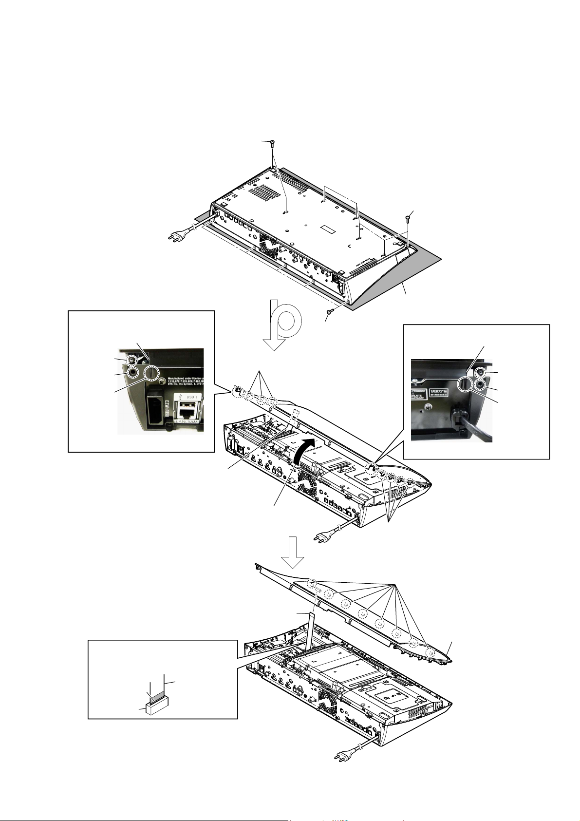
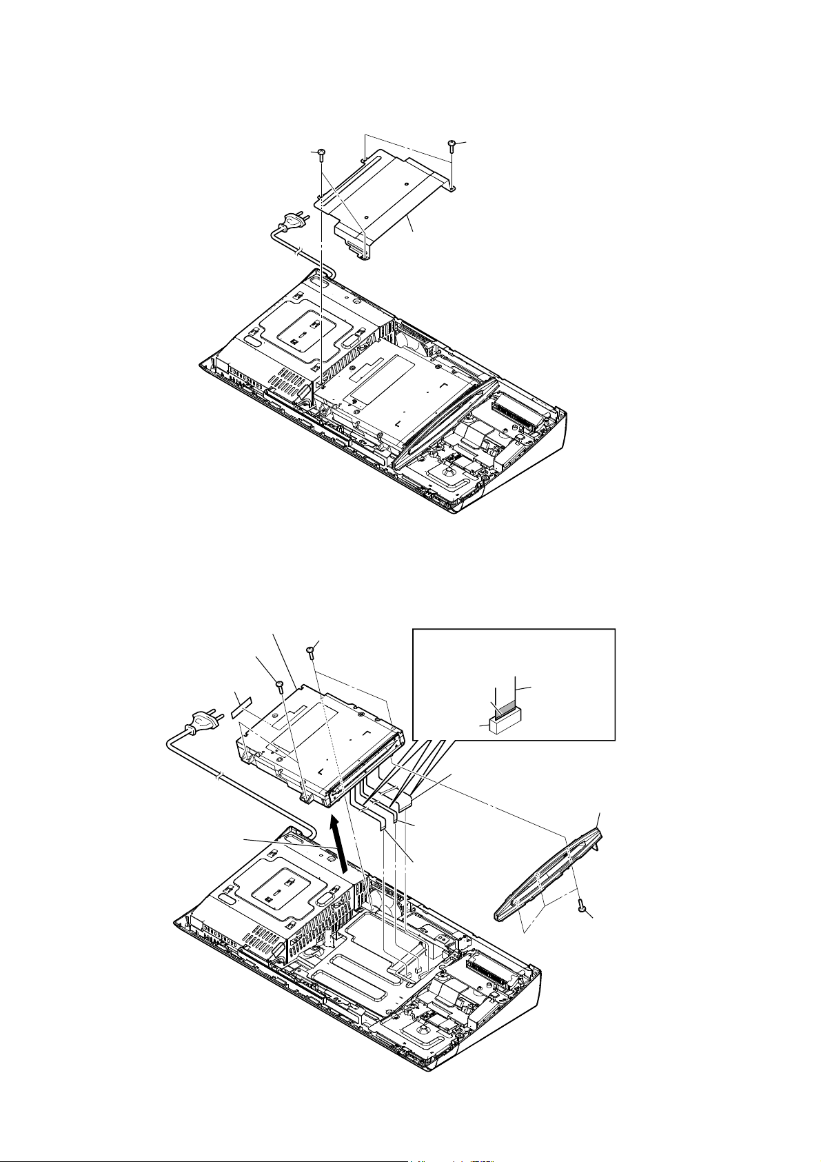
2-2. COVER (TOP) BLOCK
1 two screws
(BV DIA. 2.6 u 8)
– Rear bottom view –
Align this portion into the groove
Note 3:
and align screw boss beneath the
screw hole.
screw boss
screw hole
groove
2 three claws
HBD-N590/N790W/N890W/N990W/N995W/T79
1 five screws
(BV DIA. 2.6 u 8)
Please spread a sheet under a unit
Note 1:
not to injure cover (top).
1 five screws
(BV DIA. 2.6 u 8)
Align this portion into the groove
Note 3:
and align screw boss beneath the
screw hole.
screw boss
screw hole
groove
– Rear view –
Since the wire (flat type) (11core) is
Note 2:
connected, remove slowly.
When installing the wire (flat type),
Note 4:
ensure the coloured line.
No slanting after insertion.
coloured line
connector
wire (flat type)
– Rear view –
3 Remove the cover (top) block
in the direction of an arrow.
2 four claws
– Rear top view –
4 eight claws
5 wire (flat type) (11 core)
(CN700)
6 cover (top) block
13
HBD-N590/N790W/N890W/N990W/N995W/T79
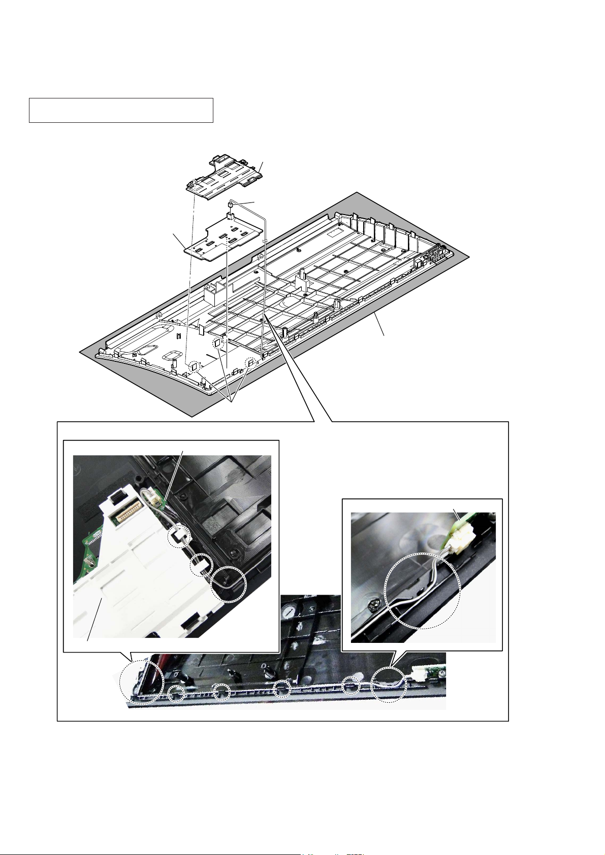
2-3. TOUCH BOARD
Note 1: When TOUCH board is defective, exchange
the complete mounted board.
3 reflector (touch) assy
1 connector
4 TOUCH board
Since it is pasted by adhesion
Note 3:
sheet, remove carefully.
(CN701)
– Bottom view –
:iUe VettiQJ
TOUCH board
2 three claws
Please spread a sheet under a unit
Note 2:
not to injure cover (top).
PWR_KEY board
14
reflector (touch) assy
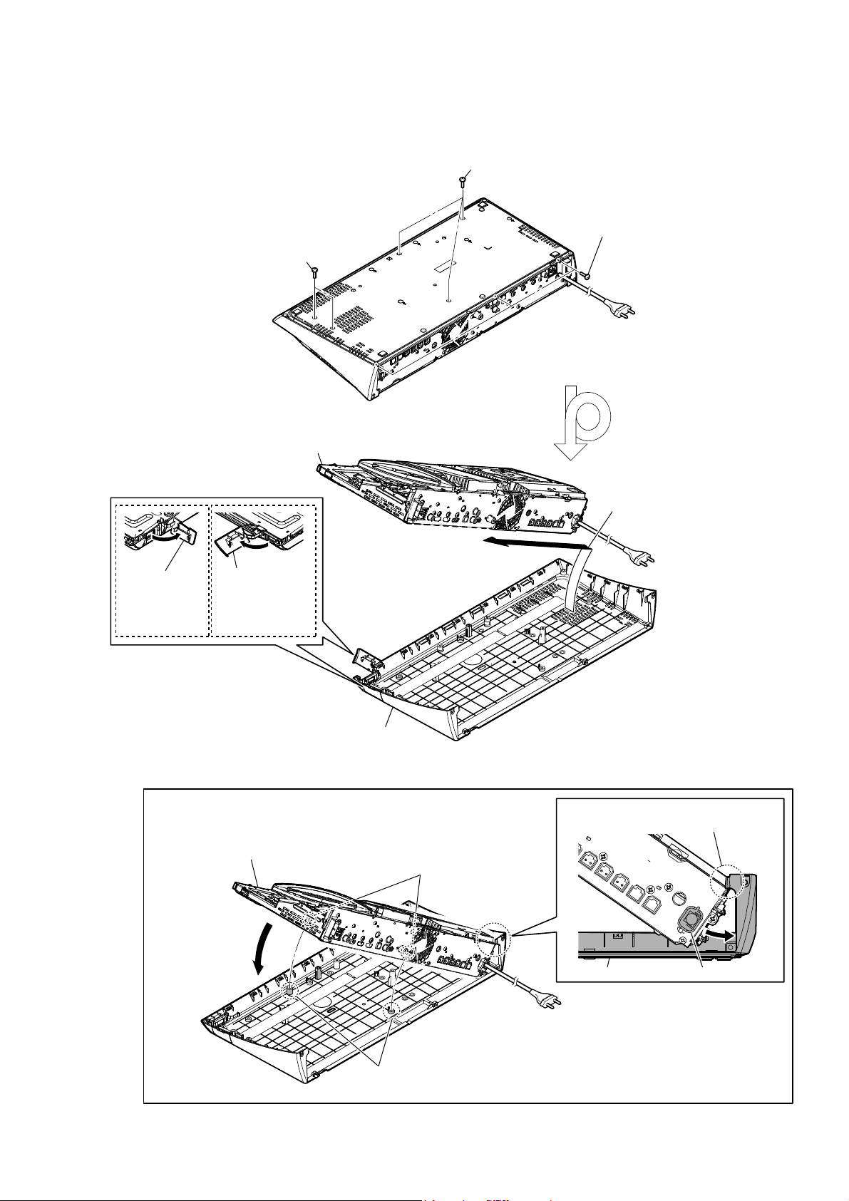
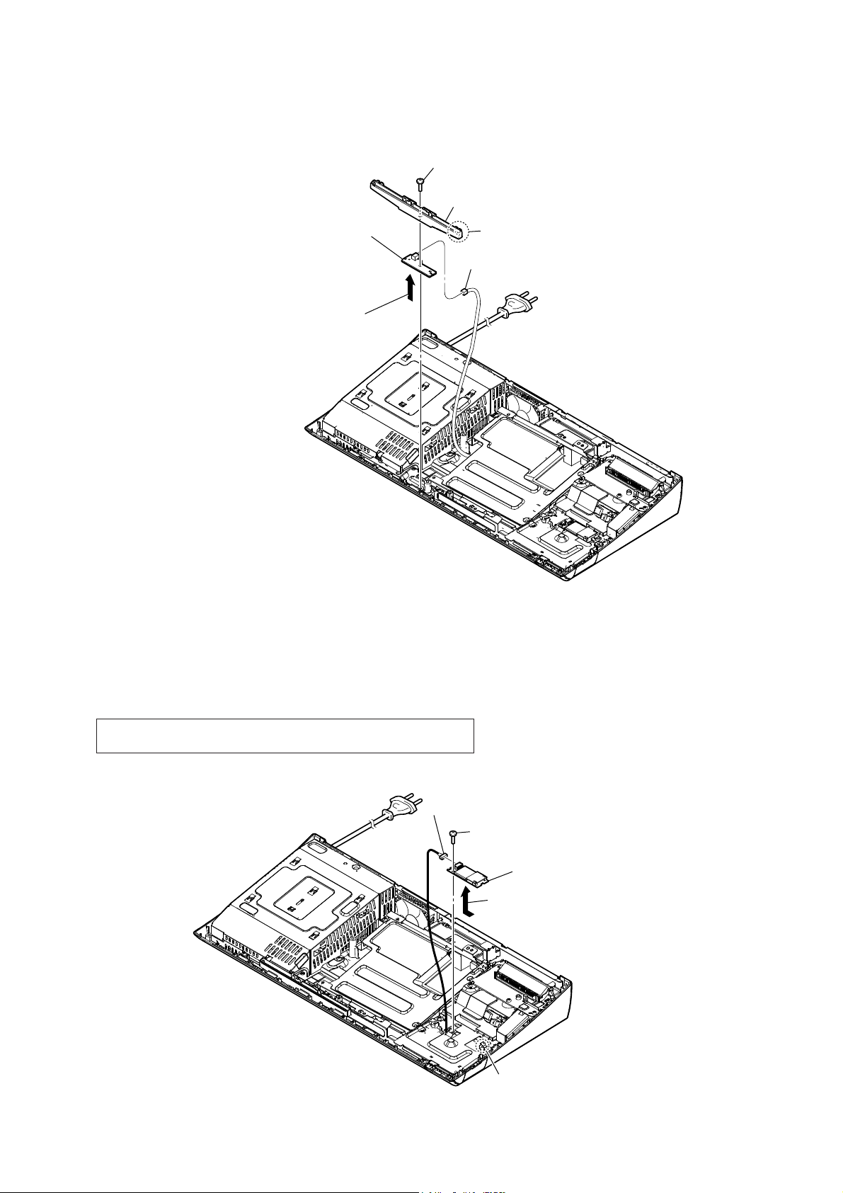
2-4. COVER (BOTTOM) BLOCK
HBD-N590/N790W/N890W/N990W/N995W/T79
Ver. 1.1
1 three screws
(BV DIA. 2.6 u 8)
2 Open the lid
(USB-side).
(N990W/N995W)
1 two screws
(BV DIA. 2.6 u 8)
4 chassis (main) block
2 Open the lid
(USB-front).
(N590/N790W/
N890W/T79)
1 three screws
(BV DIA. 2.6 u 8)
– Rear bottom view –
3 Remove the chassis (main) block
in the direction of an arrow.
5 cover (bottom) block
+RZWRLQVWDOOWKHFRYHUERWWRPEORFN
2 Align two holes to two bosses and rest
down at cover (bottom) block.
– Rear top view –
– Rear top view –
1 Slant to fit the cord bushing underneath
the claw of cover (bottom) block.
two holes
cord bushingcover (bottom) block
two bosses
15
HBD-N590/N790W/N890W/N990W/N995W/T79
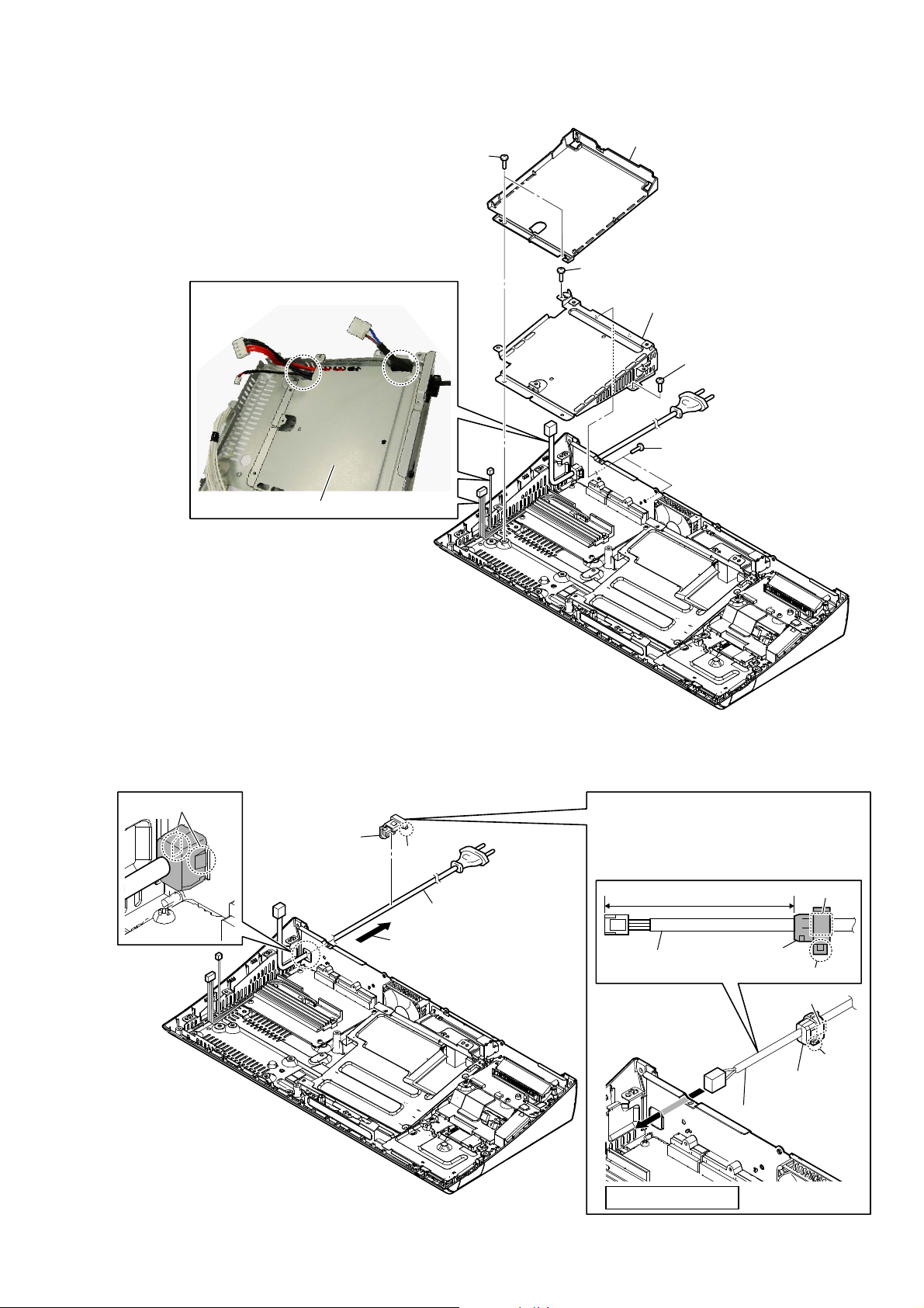
2-5. SHIELD (DRIVE)
1 two screws
(BV3)
1 two screws
(BV3)
2 shield (drive)
2-6. BD DRIVE (BSX-3)
8 sound sheet
2 Remove the BD drive block
in the direction of an arrow.
9 BD drive (BSX-3)
1 two screws
(BV3)
1 two screws
(BV3)
When installing the wire (flat type),
Note:
ensure the coloured line.
No slanting after insertion.
coloured line
connector
3 wire (flat type) (45P)
(CN1101)
5 wire (flat type)
(7 core) (CN1701)
4 wire (flat type)
(9 core) (CN1260)
wire (flat type)
7 bracket (slot)
6 three screws
(BV3)
16
2-7. LED BOARD
HBD-N590/N790W/N890W/N990W/N995W/T79
Ver. 1.1
1 screw
(BV3)
3 cover (indicator) block
6 LED board
4 Remove the LED board in
the direction of an arrow.
2 claw
5 connector
(CN330)
2-8. WIRELESS LAN CARD (WLC1) (EXCEPT N995W)
Note: When the wireless LAN card (WLC1) is replaced, refer to “CHECKING
METHOD OF NETWORK OPERATION” on servicing notes (page 9).
4 connector
1 screw
(BV3)
5 wireless LAN card (WLC1)
3 Remove the wireless LAN card (WLC1)
in the direction of an arrow.
2 claw
17
HBD-N590/N790W/N890W/N990W/N995W/T79
2-9. CHASSIS (MIDDLE) BLOCK
1 tape
5 two screws
(BV3)
6 chassis (middle) block
2 wire (flat type) (11 core)
(CN6303)
5 two screws
(BV3)
Note:
ensure the coloured line.
No slanting after insertion.
5 screw (BV3)
3 wire (flat type) (15 core)
(CN6304)
4 screw
(BV3)
When installing the wire (flat type),
wire (flat type)
coloured line
connector
2-10. BRACKET (DRIVE)
:LUHVHWWLQJ
2 three screws
(BV3)
3 bracket (drive)
1 two screws
(BV3)
bracket (drive)
18
2-11. WS BOARD BLOCK (EXCEPT N590)
When installing the wire (flat type),
Note:
ensure the coloured line.
No slanting after insertion.
coloured line
connector
HBD-N590/N790W/N890W/N990W/N995W/T79
2 two screws
(BV3)
3 WS board block
wire (flat type)
1 wire (flat type) (13 core)
(CN5909)
2-12. SHIELD (PS) BLOCK
1 four screws
(BV3)
1 three screws
(BV3)
2 shield (PS) block
19
HBD-N590/N790W/N890W/N990W/N995W/T79
2-13. SWITCHING REGULATOR (SWR1)
1 power cord connector
(CN1)
5 two screws
5 two screws
(BV3)
6 switching regulator
(SWR1)
5 screw
(BV3)
3 connector
(CN4)
2 connector
(CN101)
(BV3)
4 connector
(CN301)
Switching regulator (SWR1) setting
switching regulator (SWR1)
power cord
Check that the C351 is bended to the
Note:
position as specified in the drawing.
20
SAFETY STANDARD
coil
2-14. BRACKET (PS)
WireVeWWiQJ
HBD-N590/N790W/N890W/N990W/N995W/T79
2 insulator (bottom)
1 two screws
(B3)
4 screw
(B3)
5 bracket (PS)
4 screw
(B3)
3 two screws
(B3)
2-15. POWER CORD (AC1)
1 two claws
4 cord bushing
(FBS001)
bracket (PS)
3 claw
5 power cord (AC1)
2 Remove the cord bushing
(FBS001) in the direction
of an arrow.
Cord bushing (FBS001) setting
When installing the cord bushing (FBS001),
Note:
mind the direction of claw at type No. mark
and align into the hole and press in fully.
type No.
FBS
001
claw
power cord
80 mm
cord bushing
(FBS001)
SAFETY STANDARD
cord bushing
(FBS001)
power cord
type No.
001
FBS
claw
21
HBD-N590/N790W/N890W/N990W/N995W/T79
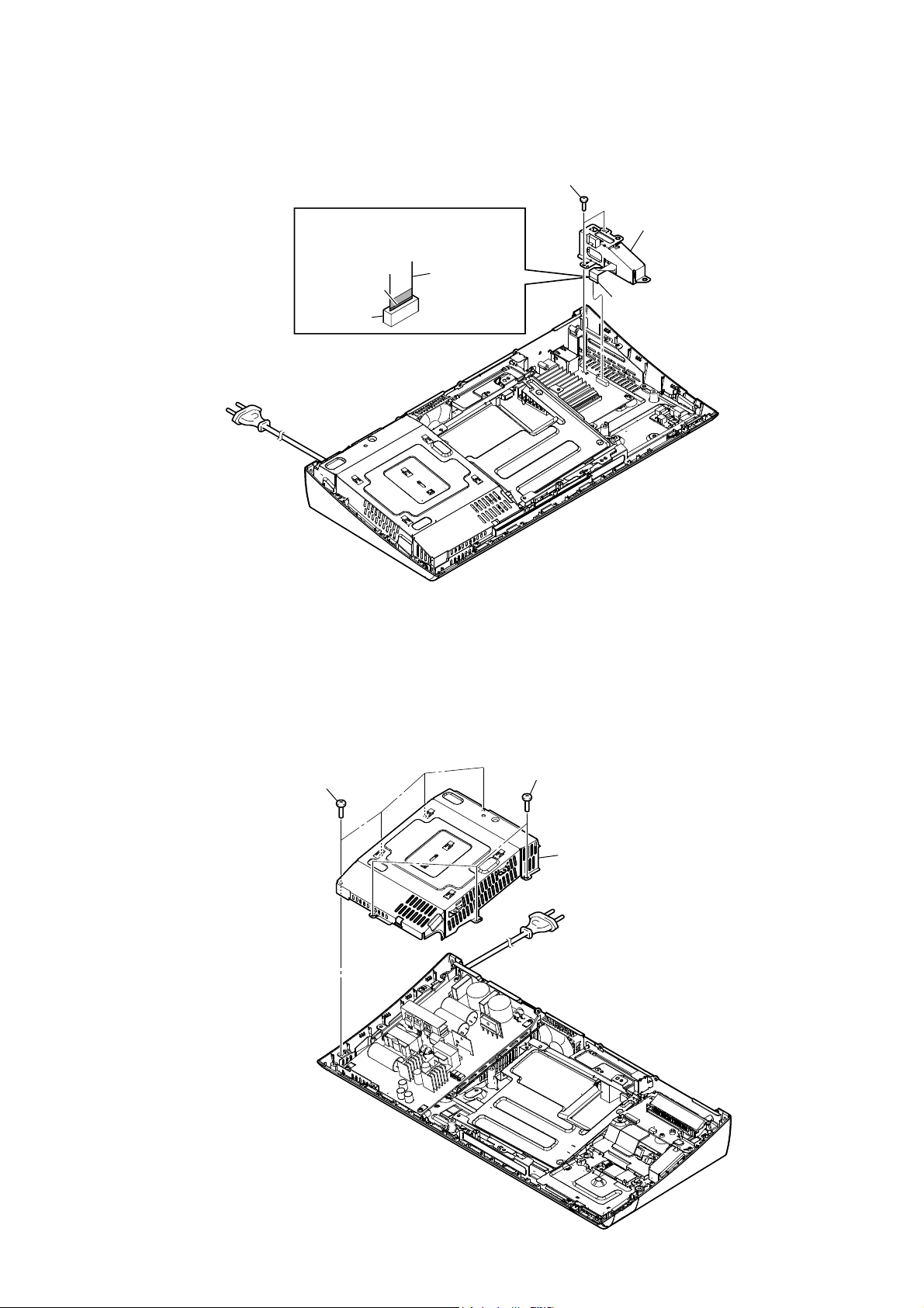
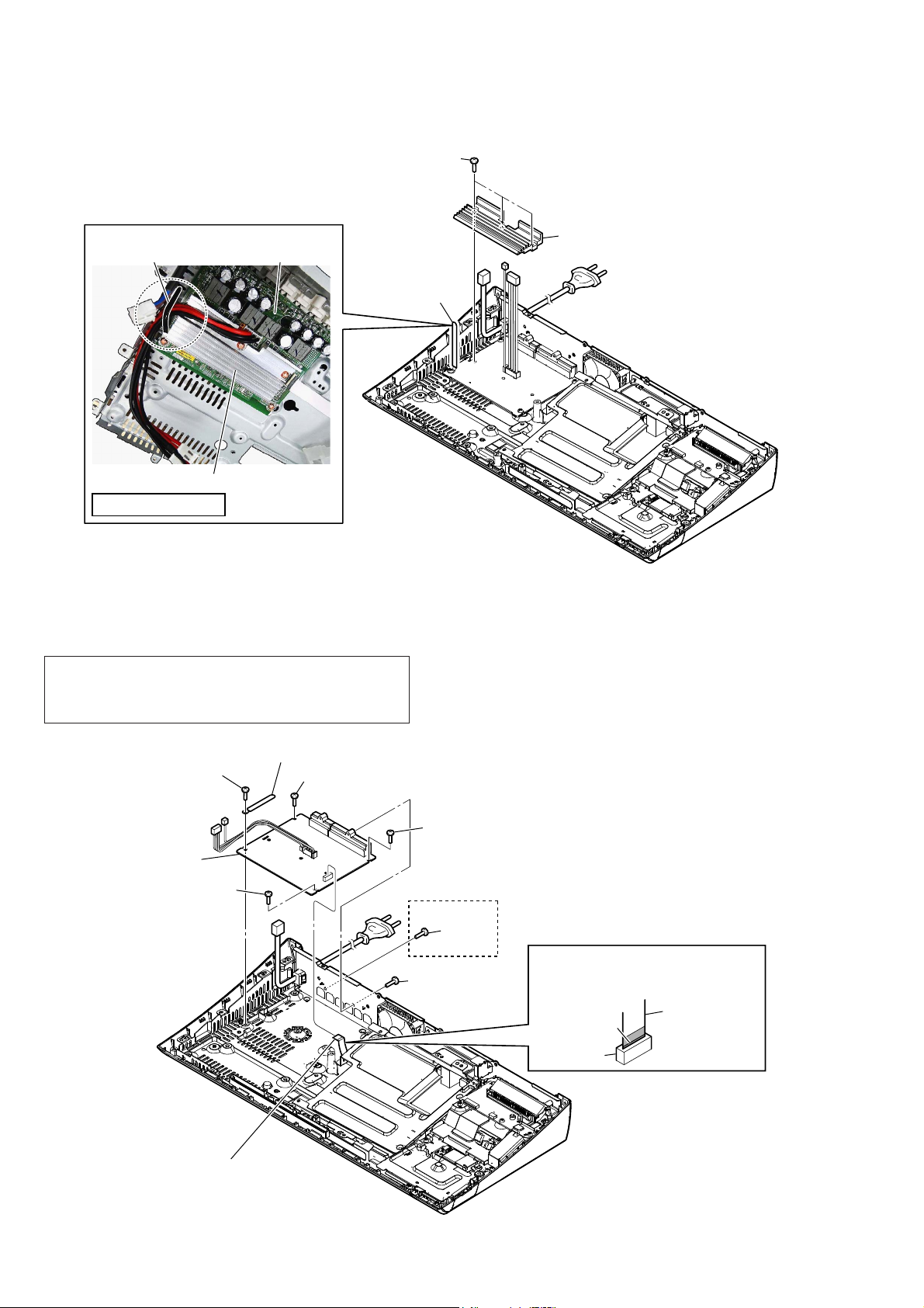
2-16. HEAT SINK (AMP)
2 three screws
(transistor)
Wire setting
NX_AMP boardclamp
1 Remove wire
from the clamp.
heat sink (AMP)
SAFETY STANDARD
2-17. NX_AMP BOARD
Note 1: When the NX_AMP board is replaced, spread the compound
referring to “NOTE OF REPLACING THE IC3102 AND
IC3302 ON THE NX_AMP BOARD AND THE COMPLETE
NX_AMP BOARD” on servicing notes (page 8)
3 heat sink (AMP)
4 clamp
3 screw
(B3)
5 NX_AMP board
3 screw
(B3)
1 wire (flat type)
(22 core) (CN3504) (EXCEPT N590)/
(24 core) (CN3505) (N590)
3 screw
(B3)
3 screw
(B3)
2 screw
(B3)
2 screw
(B3)
(N590)
When installing the wire (flat type),
Note 2:
ensure the coloured line.
No slanting after insertion.
coloured line
connector
wire (flat type)
22

HBD-N590/N790W/N890W/N990W/N995W/T79
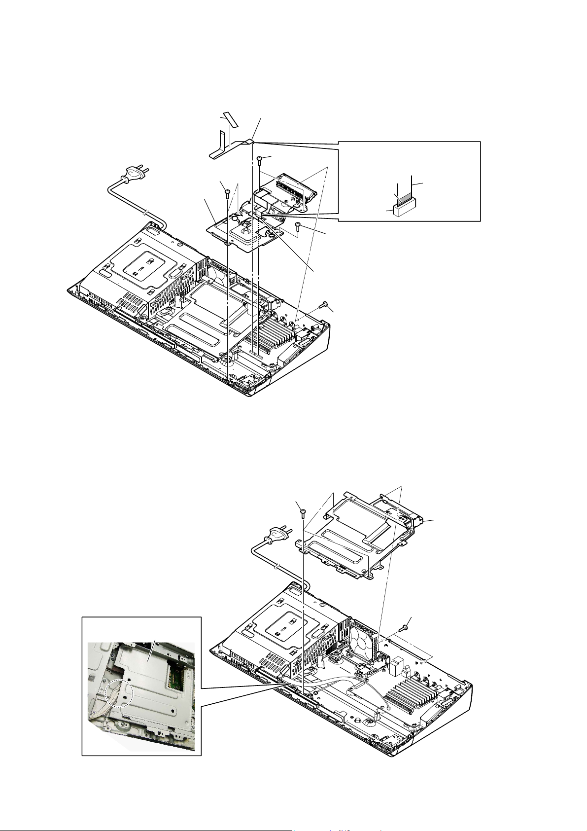
2-18. MB-149 BOARD
Note 1: When the MB-149 board is replaced, refer to “CHECKING METHOD
OF NETWORK OPERATION” on servicing notes (page 9).
1 connector
WireVeWWiQJ
tape guide line
(CN5301)
MB-149 board
2 wire (flat type)
(22 core) (CN5905) (EXCEPT N590)/
(24 core) (CN5904) (N590)
3 wire (flat type) (7 core) (CN5902)
4 connector
(CN1801)
When installing the wire (flat type),
Note 2:
ensure the coloured line.
No slanting after insertion.
coloured line
connector
wire (flat type)
Ver. 1.1
qa connector
(CN6301)
8 screw
(BV3)
qs MB-149 board
5 connector (CN601)
USB boardtape
Arrange the wire connected with
Note 3:
the wireless LAN card to make the
outside of MB-149 board crawl.
8 two screws
(BV3)
(N590/N790W/N890W/T79) (N990W/N995W)
A
B
C
MB-149 boardMB-149 board
USB board
Arrange the wire connected with
Note 3:
the wireless LAN card to make the
outside of MB-149 board crawl.
(N590)
8 screw (BV3)
9 Remove the MB-149 board
in the direction of an arrow.
8 screw
(BV3)
A
8 screw (BV3)
B
C
0 connector
(CN602)
6 two screws
(BV3)
7 three screws
(P3 u 3)
6 screw
(BV3)
23
HBD-N590/N790W/N890W/N990W/N995W/T79
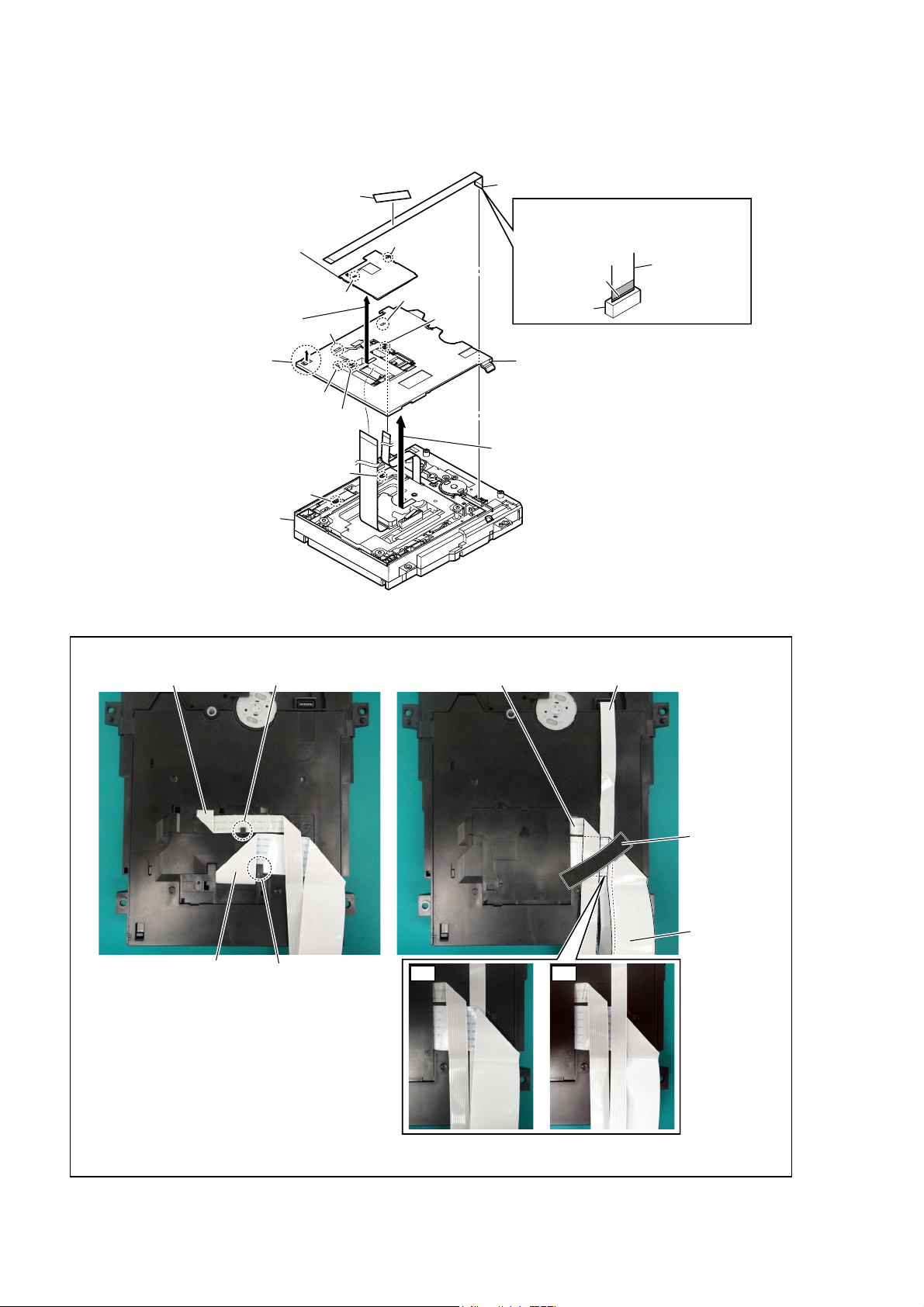
2-19. BOTTOM COVER
tape
1
FFC guide
5
Note 2:
unite the position of two holes of
FFC guide with two bosses of
bottom cover.
When installing the FFC guide,
4 Remove the
in the direction of an arrow.
FFC guide
claw
6
3
claw
hole
hole
boss
hole
hole
boss
wire (flat type) (7 core)
2
When installing the wire (flat type),
Note 1:
ensure the coloured line.
No slanting after insertion.
coloured line
connector
bottom cover
8
Note 3:
unite the position of two holes of
bottom cover with two bosses of
loading assy.
When installing the bottom cover,
wire (flat type)
7 Remove the
boss
boss
loading assy
– BD drive bottom view –
:ire (Ilat t\Se) setting
wire (flat type) (9 core) wire (flat type) (9 core) wire (flat type) (7 core)
claw
in the direction of an arrow.
bottom cover
tape
24
flexible flat cable (45P)
– BD drive bottom view –
(FFC guide uninstalled)
claw
flexible flat cable
(45P)
OK NG
– BD drive bottom view –
(FFC guide installed)
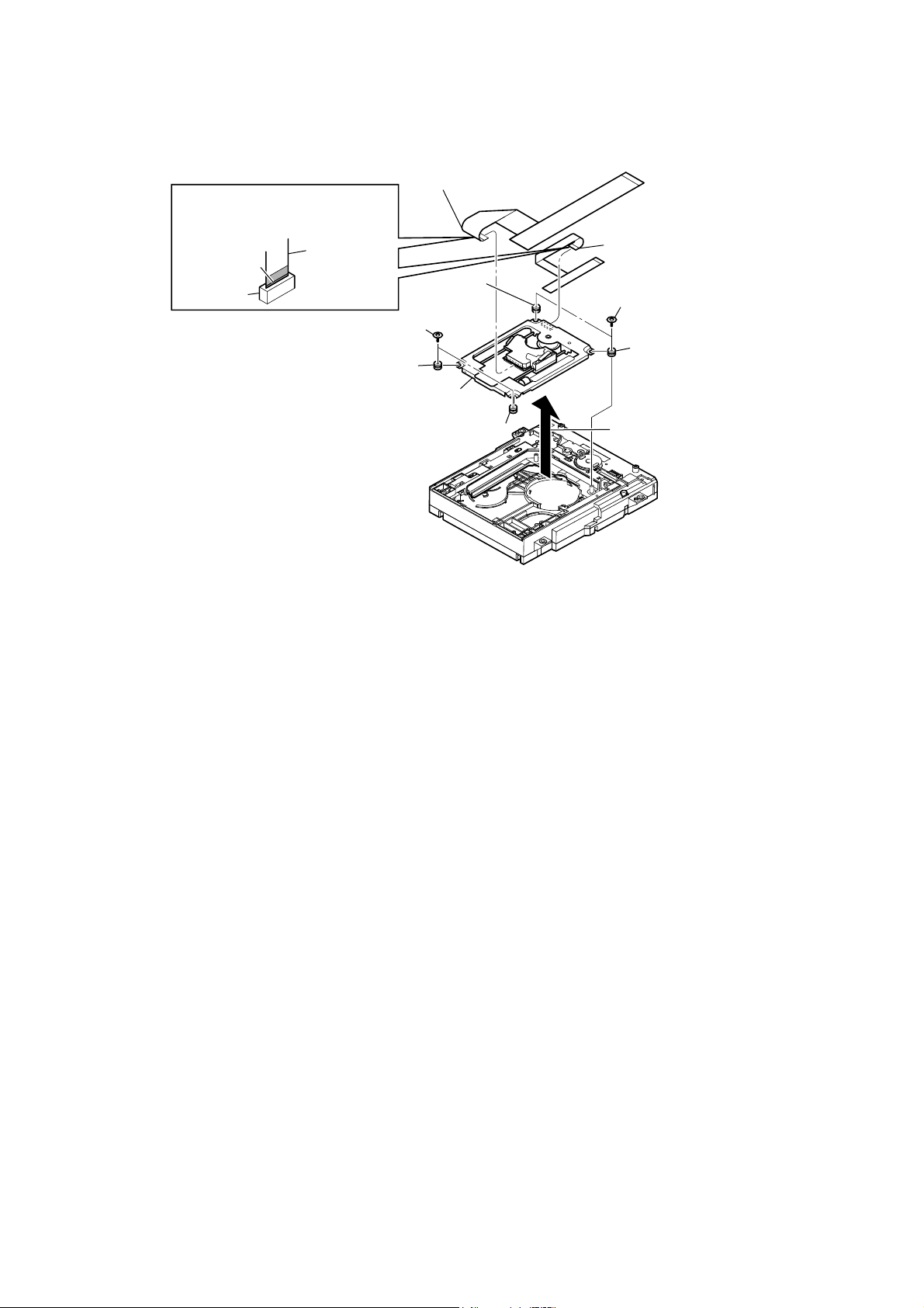
2-20. OPTICAL PICK-UP (KEM-480AAA)
HBD-N590/N790W/N890W/N990W/N995W/T79
When installing the wire (flat type),
Note:
ensure the coloured line.
No slanting after insertion.
coloured line
connector
wire (flat type)
1 two float screws (S)
4 flexible flat cable (45P)
5 insulator
5 insulator
6 optical pick-up
(KEM-480AAA)
5 insulator
– BD drive bottom view –
3 wire (flat type) (9 core)
1 two float screws (S)
5 insulator
2 Remove the optical pick-up block
in the direction of an arrow.
25
HBD-N590/N790W/N890W/N990W/N995W/T79
Ver. 1.1
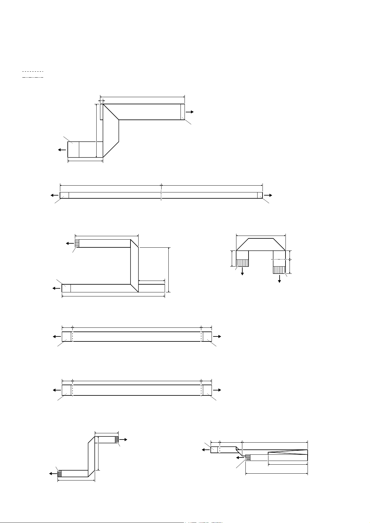
2-21. HOW TO BEND WIRE (FLAT TYPE)
: Mountain fold
: Valley fold
IOH[LEOHIODWFDEOHOHQJWKPP5HI1R))&
120 mm
4 mm
MAIN board
(CN1101)
The lower side
is contact side.
optical pick-up
(KEM-480AAA)
ZLUHIODWW\SHFRUHOHQJWKPP5HI1R))&
MAIN board
(CN1701)
The lower side
is contact side.
ZLUHIODWW\SHFRUHOHQJWKPP5HI1R))&
optical pick-up
(KEM-480AAA)
The upper side is
terminal side.
The lower side
is contact side.
MAIN board
(CN1260)
76 mm
50 mm
115 mm 115 mm
72 mm
30 mm
117 mm
51 mm
The lower side
is contact side.
MS-486 board
The lower side
is contact side.
ZLUHIODWW\SHFRUHOHQJWKPP5HI1R))&
28 mm
9 mm
The upper side is
terminal side.
MAIN board
(CN5902)
tuner
5 mm
8 mm
The upper side is
terminal side.
IOH[LEOHIODWFDEOHFRUHOHQJWKPP5HI1R))&1:1:1:1:7
12 mm12 mm 146 mm
MAIN board
(CN5905)
The lower side
is contact side.
IOH[LEOHIODWFDEOHFRUHOHQJWKPP5HI1R))&1
12 mm12 mm 146 mm
MAIN board
(CN5904)
The lower side
is contact side.
ZLUHIODWW\SHFRUHOHQJWKPP5HI1R))& ZLUHIODWW\SHFRUHOHQJWKPP5HI1R))&
The upper side is
terminal side.
MAIN board
(CN6304)
42 mm
27 mm
31 mm
FL board
(CN903)
The upper side is
terminal side.
The lower side
is contact side.
MAIN board
(CN6303)
TOUCH board
The upper side is
terminal side.
NX_AMP board
(CN3504)
The lower side
is contact side.
NX_AMP board
(CN3505)
The lower side
is contact side.
8 mm 20 mm 58 mm
(CN700)
55 mm
35 mm
26
HBD-N590/N790W/N890W/N990W/N995W/T79
SECTION 3
Ver. 1.1
TEST MODE
COLD RESET (MAIN UNIT)
The cold reset clears data except BD/DVD data stored in the RAM
to initial conditions. Execute this mode when returning the unit to
the customers.
Procedure:
1. Press the [
] button to turn the power on.
?/1
2. Touch the [x] and [VOL –] sensors simultaneously and hold
down (around 5 seconds).
3. The message “RESET” appears on fl uorescent indicator tube,
then becomes standby states.
COLD RESET (SURROUND AMPLIFIER)
(HBD-N790W/N890W/N990W/N995W/T79 only)
Execute this mode when returning the unit to the customers.
Note 1: The main unit corresponding to TA-SA300WR, wireless trans-
ceivers (EZW-RT50 (HBD-N790W/N890W/N990W/T79) or
EZW-RT20 (HBD-N995W)) (2 units) and the remote commander corresponding to the main unit are necessary to execute this
mode.
Procedure:
1. Insert the wireless transceiver (EZW-RT50 (HBD-N790W/
N890W/N990W/T79) or EZW-RT20 (HBD-N995W)) of the
attachment in the wireless transceiver slot in the back of the
main unit (HBD-N790W/N890W/N990W/N995W/T79) and
the surround amplifi er (TA-SA300WR).
Rear panel of the main unit
(HBD-N790W/N890W/N990W/N995W/T79)
5. When a wireless transceiving becomes effective, the [LINK/
STANDBY] indicator of surround amplifi er (TA-SA300WR)
lights to green.
Note 2: Refer to the operating instructions when the [LINK/STAND-
BY] indicator of surround amplifi er (TA-SA300WR) doesn’t
light.
LINK/STANDBY indicator
.+0-56#0&$;
6. Press the button in order of the [DISPLAY] [0] [7] [2]
[SUBTITLE] on the remote commander corresponding to
main unit aiming at the main unit.
7. Confi rm the [LINK/STANDBY] indicator of TA-SA300WR is
orange lighting after step 3 is executed.
8. The AC plug of TA-SA300WR is pulled out to turn off the
system.
Note 3: Please insert it after confi rming the [LINK/STANDBY] indi-
cator of TA-SA300WR has been turned off when you insert
the AC plug again.
DEMO MODE
This mode let you lock the disc slot. When this mode is activated,
the disc will not eject when the [Z] sensor is touched. The message “DEMO LOCK” will be displayed on the fluorescent indicator tube.
Procedure:
1. Press the [
] button to turn the power on.
?/1
2. Insert a disc.
3. Press the [HOME] button on the remote commander to enter
the home menu.
4. Touch the [x] and [Z] sensors simultaneously and hold down
until “DEMO.LOCK” or “DEMO OFF” displayed on the fluorescent indicator tube (around 5 seconds).
Wireless
transceiver
(EZW-RT50 (HBD-N790W/
N890W/N990W/T79) or
EZW-RT20 (HBD-N995W))
Rear panel of the surround amplifier
(TA-SA300WR)
W-RT50
EZ
Wireless
transceiver
(EZW-RT50 (HBD-N790W/
N890W/N990W/T79) or
EZW-RT20 (HBD-N995W))
2. Connect the AC power cord of the main unit (HBD-N790W/
N890W/N990W/N995W/T79).
3. Press the [
] button on the main unit (HBD-N790W/
\/1
N890W/N990W/N995W/T79).
4. Connect the AC power cord of the surround amplifi er (TA-
SA300WR).
Releasing method:
Touch the [x] and [Z] sensors simultaneously and hold down until
“DEMO OFF” displayed on the fl uorescent indicator tube (arround
5 seconds).
27
HBD-N590/N790W/N890W/N990W/N995W/T79
PANEL TEST
Procedure:
1. Press the [
] button to turn the power on.
?/1
2. Press button in order of the [DISPLAY] [0] [0] [1]
[SUBTITLE] on the remote commander (Make the interval
when each button is pressed within two seconds).
3. All segments in fl uorescent indicator tube are lighted up. And
half segments in fl uorescent indicator tube are lighted up, oth-
ers half segments in fl uorescent indicator tube are lighted up,
then all segments in fl uorescent indicator tube are lighted up.
This operation is repeated.
4. When all segments in fl uorescent indicator tube are lighted up
in the state of step 3, press the [VOL +] button on the remote
commander and model information is displayed on the fl uores-
cent indicator tube.
Each time the [VOL +] button on the remote commander is
pressed, the display changes from destination information,
STR version in this order, and returns to the model information display.
Each time the [VOL –] button on the remote commander is
pressed, the version and date are switched.
5. In the state of step 3, press the [FUNCTION] button on the
remote commander and “K 0” is displayed on the fluorescent
indicator tube.
“K 0” value increases whenever a button or sensor on the unit
is pressed. However, once a button or sensor has been pressed,
it is no longed taken into account.
All button and sensors on the unit are pressed, “OK” and “K 7”
are alternately displayed on the fluorescent indicator tube.
6. In the state of step 3, press the [VOL –] button on the remote
commander and “RM” is displayed on the fluorescent indicator tube.
Confirm that “L RM R” is displayed on the fluorescent in-
dicator tube, while pressing the [VOL –] button on the remote
commander.
The remote control receiver (IC903 on the FL board and IC951
on the SIRCS board) may be defective when “L” and “R” are
not displayed.
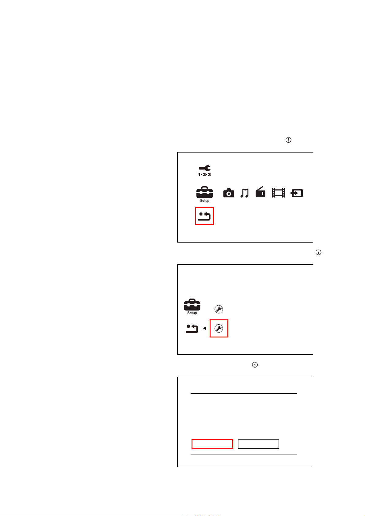
FACTORY INITIALIZE
Return all of the unit setting to their factory defaults.
Note 1: Disconnect the following connections when you use this mode.
Front USB
Rear USB
LAN
HDMI IN 1
HDMI IN 2
Note 2: The operation in this mode must use a remote commander and TV
monitor.
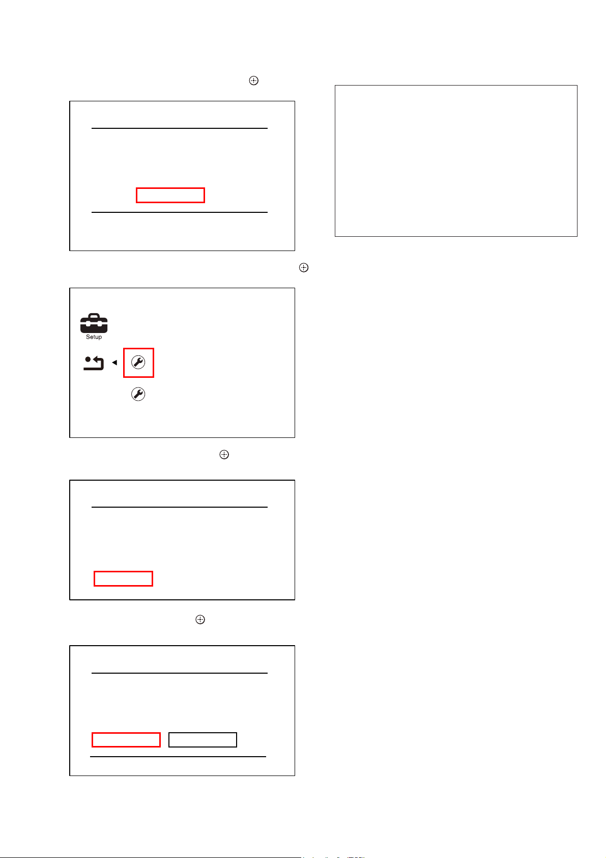
Procedure:
1. Press the [
] button to turn the power on.
?/1
2. Press the [HOME] button on the remote commander, and the
home menu is displayed.
3. Select “Setup” “Resetting”, and press the [
] button on the
remote commander.
Easy Setup
Resetting
4. Select “Initialize Personal Information”, and press the [ ]
button on the remote commander.
Releasing method:
To release from this mode, press the [
?/1
] button.
DISC SLOT LOCK MODE
The EJECT operation by main unit, remote commander, and CEC
(path-through) can be prohibited.
Procedure:
1. Press the [\/1] button to turn the power on.
2. Insert a disc.
3. Press button in order of the [DISPLAY] [0] [0] [4]
[SUBTITLE] on the remote commander.
(Make the interval when each button is pressed within two sec-
onds)
4. “TLK ON” is displayed on the fl uorescent indicator tube, and
the EJECT operation by main unit, remote commander, and
CEC (path-through) is prohibited.
Releasing method:
1. Press button in order of the [DISPLAY] [0] [0] [4]
[SUBTITLE] on the remote commander.
(Make the interval when each button is pressed within two sec-
onds)
2. “TLK OFF” is displayed on the fl uorescent indicator tube, and
the EJECT operation by main unit, remote commander, and
CEC (path-through) become effective.
Reset to Factory Default Settings
Initialize Personal Information
Erase personal data when disposing
5. Select “OK”, and press the [ ] button on the remote commander.
Initialize Personal Information
The information below will be deleted.
Do you want to proceed?
- Playback history
- Internet video utilization information
OK
Cancel
28
HBD-N590/N790W/N890W/N990W/N995W/T79
6. The message “Close” appears, and press the [ ] button on the
remote commander.
Initialize Personal Information
Initialization complete.
Close
7. Select “Reset to Factory Default Settings”, and press the [ ]
button on the remote commander.
Reset to Factory Default Settings
Restore each setting to the factory d
Initialize Personal Information
8. Select “All Settings”, and press the [ ] button on the remote
commander.
Reset to Factory Default Settings
Parental Control Settings
Music Settings
System Settings
Network Settings
External Input Settings
All Settings
9. Select “Start”, and press the [ ] button on the remote commander.
BD SERVICE MODE
[Wireless checking fail on M07.R.179]
Due to software bug in M07.R.179, currently Service mode do not support wireless checking features this version of software.
For service to confi rm the wireless checking, please update customer
sets to latest version of software. By using network upgrade method
or Disc upgrade method. After fi nish upgraded, Service member can
perform wireless checking as mention in wireless LAN checking pages.
Or
Confi rm wireless LAN connection from customer mode, in case of
Wireless connection successfully establish. The wireless Lan network
connection will be judge as OK.
Date: 26 January 2011
Note: The operation in this mode must use a remote commander and TV
monitor.
Setting method of the BD service mode:
1. Connect this unit with TV monitor.
2. Press the [
] button to turn the power on.
?/1
3. Press button in order of the [DISPLAY] [0] [2] [1]
[SUBTITLE] on the remote commander. (Make the interval
when each button is pressed within two seconds)
4. Enter the BD service mode. The OSD menu on TV monitor
can be operated by remote commander.
1. Main Functions
• Diag
Performs unit test of devices installed on the board.
• Display Error Log
Error log is displayed. Displayed contents can also be saved in
an USB memory device.
• Factory Initialize
Restores the unit to its factory settings.
• Network
Checks the wired network connection.
• Version Up
Not used.
• System Information
Displays the system information of the unit.
Displays information such as the software version, drive infor-
mation, etc.
• EMC Test Mode
Not used.
• Drive
Write drive OP data and check drive.
• HDD mode
Not used.
All Settings
Restore all settings to the factory default
settings. The system will turn off after
reset.
Start
Cancel
10. Initialization ends when the message “WELCOME” on the
fl uorescent indicator tube disappears.
29
HBD-N590/N790W/N890W/N990W/N995W/T79
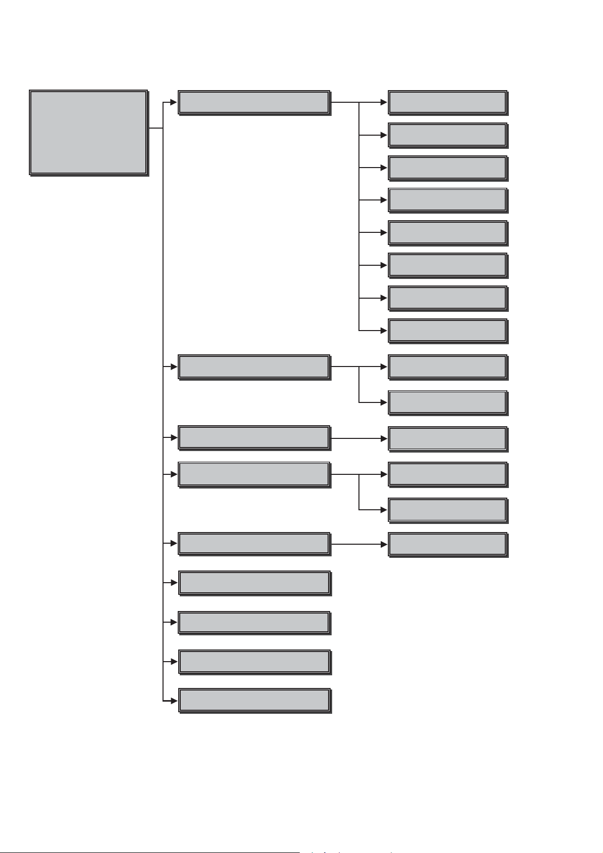
2. Menu Tree
Service Mode Menu
Service Mode Menu
[1] Diag
[1] Diag
[2] Log
[2] Log
[3] Factory Initialize
[3] Factory Initialize
[4] Network
[4] Network
[5] Version Up
[5] Version Up
[6] System Information
[6] System Information
[7] EMC Test Mode
[8] Drive
[9] HDD Mode
Diag
Diag Test
Log
Displays Error Log
Device Test
Front US%D$CIFcon test
Video Test
Video output test
$udio Test
$udio output test
$udio Input Test
Not used
:ireless L$N Test
Not used
Mic Test
Not used
HDMI Input Test
Not used
Transcoder Test
Not used
Error Log
Displays error log
Factory Initialize
Initialize default setting
Network
Network diagnosis for wired
Version Up
Not used
System Information
Displays system information
EMC Test Mode
Not used
Drive
Write drive OP data and check drive
HDD log
Not used
Start Initialize
Initialize default setting fot the unit
Ifconfig
View network status
Ping
Confirm network connection
Start Update
Not used
30
HDD Mode
Not used
 Loading...