

Sony HBD-N7100W, HBD-N7100WL, HBD-N8100W, HBD-N9100W, HBD-N9100WL Service Manual
...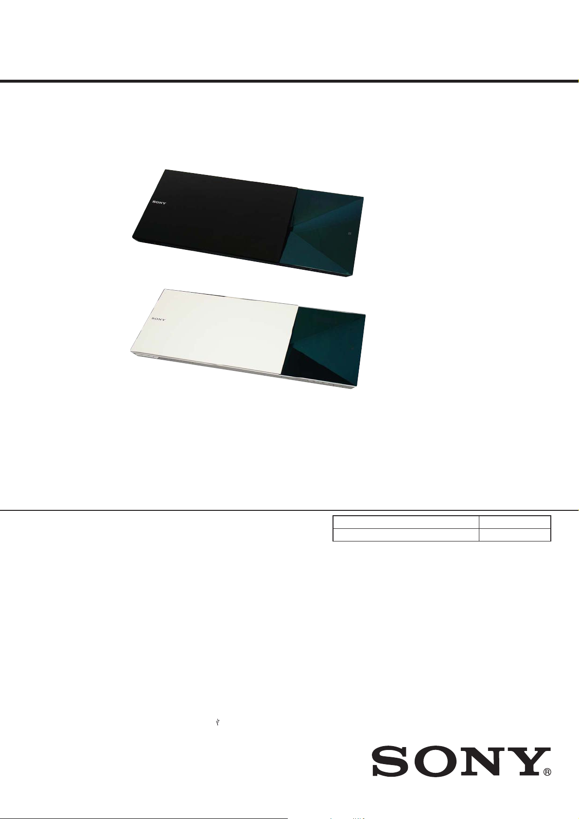
HBD-N7100W/N7100WL/N8100W/N9100W/
N9100WL/N9150W/N9150WL/N9900SH
SERVICE MANUAL
Ver. 1.2 2014.04
Photo: HBD-N8100W
US Model
HBD-N7100W/N8100W
Canadian Model
Latin American Model
HBD-N9100W
AEP Model
HBD-N7100W/N7100WL/N8100W/
N9100W/N9100WL
UK Model
HBD-N7100W/N7100WL/N9100W
E Model
HBD-N9100WL
Australian Model
Thai Model
HBD-N9100W/N9100WL
Chinese Model
HBD-N9150W/N9150WL
Photo: HBD-N9150WL
• HBD-N7100W is the Blu-ray discTM/DVD receiver in BDV-N7100W.
• HBD-N7100WL is the Blu-ray disc
• HBD-N8100W is the Blu-ray disc
TM
/DVD receiver in BDV-N7100WL.
TM
/DVD receiver in BDV-N8100W.
• HBD-N9100W is the Blu-ray discTM/DVD receiver in BDV-N9100W.
• HBD-N9100WL is the Blu-ray discTM/DVD receiver in BDV-N9100WL.
• HBD-N9150W is the Blu-ray disc
• HBD-N9150WL is the Blu-ray discTM/DVD receiver in BDV-N9150WL.
• HBD-N9900SH is the Blu-ray disc
TM
/DVD receiver in BDV-N9150W.
TM
/DVD receiver in BDV-N9900SH.
• In order to perform the operation checking, all the units contained in this unit are needed.
Model Name Using Similar Mechanism NEW
Optical Pick-up Name KEM-480AHA
SPECIFICATIONS
Amplifier Section
US model:
AUDIO POWER SPECIFICATIONS
POWER OUTPUT AND TOTAL
HARMONIC DISTORTION:
(FTC)
Front L + Front R:
With 6 ohms loads, both channels driven,
from 180 Hz – 20,000 Hz; rated 75 watts
per channel minimum RMS power, with
no more than 1% total harmonic
distortion from 250 milliwatts to rated
output.
Chinese model:
POWER OUTPUT
Front L/Front R:
35 W (per channel at 8 ohms, 1 kHz)
Center:
35 W (at 8 ohms, 1 kHz)
Subwoofer:
35 W (at 8 ohms, 80 Hz)
Other models:
POWER OUTPUT (rated)
Front L/Front R:
125 W + 125 W (at 6 ohms, 1 kHz,
1% THD)
POWER OUTPUT (reference)
Front L/Front R:
200 W (per channel at 6 ohms, 1 kHz)
Center:
200 W (at 6 ohms, 1 kHz)
Subwoofer:
200 W (at 6 ohms, 80 Hz)
Inputs (Analog)
AUDIO (AUDIO IN)
Sensitivity: 1.8 V/600 mV
Inputs (Digital)
TV (Audio Return Channel/OPTICAL)
Supported formats: LPCM 2CH (up to
48 kHz), Dolby Digital, DTS
HDMI (IN 1)/HDMI (IN 2)
Supported formats: LPCM 5.1CH
(up to 48 kHz), LPCM 2CH (up to
96 kHz), Dolby Digital, DTS
HDMI Section
Connector
Type A (19pin)
BD/DVD/Super Audio CD/CD System
Signal format system
NTSC (US, Canadian and PX models)
PAL (AEP model)
NTSC/PAL (Other models)
USB Section
(USB) port:
Type A (For connecting USB memory,
memory card reader, digital still camera,
and digital video camera)
LAN Section
LAN (100) terminal
100BASE-TX Terminal
Wireless LAN Section
(Except Chinese model)
Standards Compliance
IEEE 802.11 b/g/n
Frequency and Channel
2.4 GHz band: channels 1–11
(US, Canadian and Taiwan models)
2.4 GHz band: channels 1–13
(Other models)
Bluetooth Section
Communication system
Bluetooth Specification version 3.0
Output
Bluetooth Specification Power Class 2
Maximum communication range
Line of sight approx. 10 m (33 ft)
Frequency band
2.4 GHz band
Modulation method
FHSS (Freq Hopping Spread Spectrum)
BLU-RAY DISCTM/DVD RECEIVER
9-893-701-03
2014D33-1
2014.04
©
Sony Corporation
Published by Sony Techno Create Corporation
PX Model
HBD-N7100W
Russian Model
HBD-N8100W/N9100W/N9100WL
Saudi Arabia Model
Middle East Model
HBD-N8100W/N9100W/N9900SH
Mexican Model
HBD-N7100W/N7100WL
Singapore Model
HBD-N7100W/N9100W/N9100WL
Taiwan Model
HBD-N8100W/N9100WL
Indian Model
HBD-N7100W/N9100W
Compatible Bluetooth profiles
A2DP 1.2 (Advanced Audio Distribution
Profile)
AVRCP 1.3 (Audio Video Remote
Control Profile)
Supported Codecs
SBC4), AAC
Transmission range (A2DP)
20 Hz – 20,000 Hz (Sampling frequency
44.1 kHz, 48 kHz)
1)
The actual range will vary depending on factors
such as obstacles between devices, magnetic
fields around a microwave oven, static
electricity, cordless phone, reception
sensitivity, antenna’s performance, operating
system, software application, etc.
2)
Bluetooth standard profiles indicate the purpose
of Bluetooth communication between devices.
3)
1)
Codec: Audio signal compression and
conversion format
4)
Subband Codec
– Continued on next page –
2)
3)

HBD-N7100W/N7100WL/N8100W/N9100W/N9100WL/N9150W/N9150WL/N9900SH
Ver. 1.1
FM Tuner Section
System
PLL quartz-locked digital synthesizer
Tuning range
87.5 MHz – 108.0 MHz (100 kHz step)
(US, Canadian and PX models)
87.5 MHz – 108.0 MHz (50 kHz step)
(Other models)
Antenna (aerial)
FM wire antenna (aerial)
Antenna (aerial) terminals
75 ohms, unbalanced
General
Power requirements
120 V AC, 60 Hz
(US, Canadian and Mexican models)
110 V - 240 V AC, 50/60 Hz
(110 - 240V AC area in E, Latin American (Except
Mexican, Brazilian and Argentina) and PX models)
120 V AC, 50/60 Hz
(Taiwan model)
220 V - 240 V AC, 50/60 Hz
(Other models)
Copyrights and Trademarks
s This system incorporates with Dolby*
Digital and Dolby Pro Logic adaptive matrix
surround decoder and the DTS** Digital
Surround System.
* Manufactured under license from
Dolby Laboratories. Dolby, Pro Logic,
and the double-D symbol are
trademarks of Dolby Laboratories.
**Manufactured under license under
U.S. Patent Nos: 5,956,674;
5,974,380; 6,226,616; 6,487,535;
7,212,872; 7,333,929; 7,392,195;
7,272,567 & other U.S. and worldwide
patents issued & pending. DTS-HD,
the Symbol, & DTS-HD and the
Symbol together are registered
trademarks of DTS, Inc. Product
includes software. © DTS, Inc. All
Rights Reserved.
s This system incorporates High-Definition
Multimedia Interface (HDMI
technology.
The terms HDMI and HDMI HighDefinition Multimedia Interface, and the
HDMI Logo are trademarks or registered
trademarks of HDMI Licensing LLC in the
United States and other countries.
s Java is a trademark of Oracle and/or its
affiliates.
s “DVD logo” is a trademark of DVD Format/
Logo Licensing Corporation.
s “Blu-ray Disc”, “Blu-ray”, “Blu-ray 3D”,
“BD-LIVE”, “BONUSVIEW”, and logos
are trademarks of the Blu-ray Disc
Association.
s “Blu-ray Disc”, “DVD+RW”, “DVD-RW”,
“DVD+R”, “DVD-R”, “DVD VIDEO”, and
“CD” logos are trademarks.
s “Super Audio CD” is a trademark.
s “BRAVIA” is a trademark of Sony
Corporation.
s “AVCHD 3D/Progressive” and the
“AVCHD 3D/Progressive” logo are
trademarks of Panasonic Corporation and
Sony Corporation.
s , “XMB”, and “xross media bar” are
trademarks of Sony Corporation and Sony
Computer Entertainment Inc.
s “PlayStation” is a registered trademark of
Sony Computer Entertainment Inc.
s “Sony Entertainment Network logo” and
“Sony Entertainment Network” are
trademarks of Sony Corporation.
s Music and video recognition technology and
related data are provided by Gracenote®.
Gracenote is the industry standard in music
recognition technology and related content
delivery. For more information, please visit
www.gracenote.com.
CD, DVD, Blu-ray Disc, and music and
video-related data from Gracenote, Inc.,
copyright © 2000-present Gracenote.
Gracenote Software, copyright © 2000present Gracenote. One or more patents
owned by Gracenote apply to this product
and service. See the Gracenote website for a
nonexhaustive list of applicable Gracenote
patents. Gracenote, CDDB, MusicID,
MediaVOCS, the Gracenote logo and
logotype, and the “Powered by Gracenote”
logo are either a registered trademark or a
trademark of Gracenote, Inc. in the United
States and/or other countries.
TM
)
Power consumption
On: 80 W
(US, Canadian, Mexican and Taiwan models)
On: 100 W
(Other models)
Standby: 0.3 W (at the Power Saving mode)
Dimensions (w/h/d) (approx.)
480 mm × 79 mm × 212 mm (19 in ×
1
/8 in × 8 3/8 in) incl. projecting parts
3
480 mm × 79 mm × 226 mm (19 in ×
3 1/8 in × 9 in) (with the wireless
transceiver inserted)
Mass (approx.)
3.1 kg (6 lb 14 oz)
Design and specifications are subject to
change without notice.
s Standby power consumption: 0.3W.
s Over 85% power efficiency of amplifier
block is achieved with the full digital
amplifier, S-Master.
®
s Wi-Fi
, Wi-Fi Protected Access® and Wi-Fi
Alliance® are registered marks of the Wi-Fi
Alliance.
s Wi-Fi CERTIFIED™, WPA™, WPA2™
and Wi-Fi Protected Setup™ are marks of
the Wi-Fi Alliance.
s The N Mark is a trademark or registered
trademark of NFC Forum, Inc. in the United
States and in other countries.
s Android is a trademark of Google Inc.
s The Bluetooth
s MPEG Layer-3 audio coding technology and
s This product incorporates proprietary
s Windows Media is either a registered
s DLNA™, the DLNA Logo and DLNA
s Opera® Devices SDK from Opera Software
s All other trademarks are trademarks of their
s Other system and product names are
®
registered trademarks owned by Bluetooth
SIG, Inc. and any use of such marks by Sony
Corporation is under license. Other
trademarks and trade names are those of their
respective owners.
patents licensed from Fraunhofer IIS and
Thomson.
technology under license from Verance
Corporation and is protected by U.S. Patent
7,369,677 and other U.S. and worldwide
patents issued and pending as well as
copyright and trade secret protection for
certain aspects of such technology. Cinavia
is a trademark of Verance Corporation.
Copyright 2004-2010 Verance Corporation.
All rights reserved by Verance. Reverse
engineering or disassembly is prohibited.
trademark or trademark of Microsoft
Corporation in the United States and/or other
countries.
This product is protected by certain
intellectual property rights of Microsoft
Corporation. Use or distribution of such
technology outside of this product is
prohibited without a license from Microsoft
or an authorized Microsoft subsidiary.
Content owners use Microsoft
PlayReady™ content access technology to
protect their intellectual property, includin g
copyrighted content. This device uses
PlayReady technology to access PlayReadyprotected content and/or WMDRMprotected content. If the device fails to
properly enforce restrictions on content
usage, content owners may require
Microsoft to revoke the device’s ability to
consume PlayReady-protected content.
Revocation should not affect unprotected
content or content protected by other content
access technologies. Content owners may
require you to upgrade PlayReady to access
their content. If you decline an upgrade, you
will not be able to access content that
requires the upgrade.
CERTIFIED™ are trademarks, service
marks, or certification marks of the Digital
Living Network Alliance.
ASA. Copyright 1995-2013 Opera Software
ASA. All rights reserved.
respective owners.
generally trademarks or registered
trademarks of the manufacturers. ™ and ®
marks are not indicated in this document.
word mark and logos are
®
SAFETY CHECK-OUT
After correcting the original service problem, perform the following safety check before releasing the set to the customer:
Check the antenna terminals, metal trim, “metallized” knobs,
screws, and all other exposed metal parts for AC leakage.
Check leakage as described below.
LEAKAGE TEST
The AC leakage from any exposed metal part to earth ground and
from all exposed metal parts to any exposed metal part having a
return to chassis, must not exceed 0.5 mA (500 microamperes.).
Leakage current can be measured by any one of three methods.
1. A commercial leakage tester, such as the Simpson 229 or RCA
WT-540A. Follow the manufacturers’ instructions to use these
instruments.
2. A battery-operated AC milliammeter. The Data Precision 245
digital multimeter is suitable for this job.
3. Measuring the voltage drop across a resistor by means of a
VOM or battery-operated AC voltmeter . The “limit” indication
is 0.75 V, so analog meters must have an accurate low-voltage
scale. The Simpson 250 and Sanwa SH-63Trd are examples
of a passive VOM that is suitable. Nearly all battery operated
digital multimeters that have a 2 V AC range are suitable. (See
Fig. A)
To Exposed Metal
Parts on Set
AC
1.5 kΩ0.15 μF
voltmeter
(0.75 V)
Earth Ground
Fig. A. Using an AC voltmeter to check AC leakage.
NOTES ON CHIP COMPONENT REPLACEMENT
• Never reuse a disconnected chip component.
• Notice that the minus side of a tantalum capacitor may be damaged by heat.
CAUTION
Use of controls or adjustments or performance of procedures
other than those specifi ed herein may result in hazardous radia-
tion exposure.
Pick-up unit of this appliance is classified as a
CLASS 3R LASER product. Visible and
invisible laser radiation is emitted when the
laser protective housing is opened, so be s ure
to avoid direct eye exposure.
This marking is located on the bottom
exterior.
This appliance is classified as a CLASS 1
LASER product. This marking is located on
the bottom exterior.
2

HBD-N7100W/N7100WL/N8100W/N9100W/N9100WL/N9150W/N9150WL/N9900SH
Ver. 1.1
TABLE OF CONTENTS
1. SERVICING NOTES ............................................. 4
2. DISASSEMBLY
2-1. Disassembly Flow ........................................................... 13
2-2. Cover Top Assy ............................................................... 14
2-3. Inner Door Block ............................................................ 15
2-4. BU Top Cover Block ...................................................... 16
2-5. Loading Base Block ........................................................ 17
2-6. Optical Pick-up Block ..................................................... 18
2-7. Flexible Flat Cable (45 Core) (FFC1),
Wire (Flat Type) (9 Core) (FFC2),
Wire (Flat Type) (5 Core) (FFC3) ................................... 19
2-8. Optical Pick-up (KEM-480AHA) (OP1) ........................ 20
2-9. TOUCH-F Board Block .................................................. 20
2-10. Cover (Bottom) Block .................................................... 21
2-11. WLAN/BT Combo Card (WBC1) .................................. 22
2-12. FAN-LED Board ............................................................. 22
2-13. TUNER-IO Board ........................................................... 23
2-14. FL Board ......................................................................... 23
2-15. Shield (Power) Block ...................................................... 24
2-16. Shield (MB) Block .......................................................... 25
2-17. WS Board Block ............................................................. 25
2-18. DC Fan (M1) ................................................................... 26
2-19. Power Cord (AC1) .......................................................... 26
2-20. Switching Regulator (SWR1), Insulator (Bottom) ......... 27
2-21. Shield (AMP) Block ....................................................... 27
2-22. MB1004 Board ............................................................... 28
2-23. NJ_AMP Board ............................................................... 29
2-24. How to Bend Wire (Flat Type) ........................................ 30
3. TEST MODE ............................................................ 31
4. ELECTRICAL CHECK ......................................... 43
5. DIAGRAMS
5-1. Block Diagram - SERVO Section - ................................ 44
5-2. Block Diagram - MEMORY Section - ............................ 45
5-3. Block Diagram - MAIN Section - ................................... 46
5-4. Block Diagram - AMP Section - ..................................... 47
5-5. Block Diagram - POWER SUPPLY Section - ................ 48
5-6. Printed Wiring Board - MB1004 Board (Side A) - ......... 50
5-7. Printed Wiring Board - MB1004 Board (Side B) - ......... 51
5-8. Schematic Diagram - MB1004 Board (1/11) -................ 52
5-9. Schematic Diagram - MB1004 Board (2/11) -................ 53
5-10. Schematic Diagram - MB1004 Board (3/11) -................ 54
5-11. Schematic Diagram - MB1004 Board (4/11) -................ 55
5-12. Schematic Diagram - MB1004 Board (5/11) -................ 56
5-13. Schematic Diagram - MB1004 Board (6/11) -................ 57
5-14. Schematic Diagram - MB1004 Board (7/11) -................ 58
5-15. Schematic Diagram - MB1004 Board (8/11) -................ 59
5-16. Schematic Diagram - MB1004 Board (9/11) -................ 60
5-17. Schematic Diagram - MB1004 Board (10/11) -.............. 61
5-18. Schematic Diagram - MB1004 Board (11/11) - .............. 62
5-19. Printed Wiring Boards - REAR PANEL Section - .......... 63
5-20. Schematic Diagram - TUNER-IO Board - ...................... 64
5-21. Schematic Diagram - FAN-LED/WS Boards - ............... 65
5-22. Printed Wiring Board - NJ_AMP Board - ....................... 66
5-23. Schematic Diagram - NJ_AMP Board - ......................... 67
5-24. Printed Wiring Boards - CHUKEI/FL Boards - .............. 68
5-25. Schematic Diagram - CHUKEI/FL Boards - .................. 69
5-26. Printed Wiring Boards
- FRONT/TOP PANEL Section - .................................... 70
5-27. Schematic Diagram - FRONT/TOP PANEL Section - ... 71
6. EXPLODED VIEWS
6-1. Overall Section ............................................................... 91
6-2. Mechanism Deck Section ............................................... 92
6-3. Optical Pick-up Section .................................................. 93
6-4. TOUCH-F Board Section ............................................... 94
6-5. Cover (Bottom) Section .................................................. 95
6-6. Shield (Power) Section ................................................... 96
6-7. Switching Regulator Section .......................................... 97
6-8. NJ_AMP Board Section .................................................. 98
6-9. MB1004 Board Section .................................................. 99
7. ELECTRICAL PARTS LIST .............................. 100
SAFETY-RELATED COMPONENT WARNING!
COMPONENTS IDENTIFIED BY MARK 0 OR DOTTED LINE
WITH MARK 0 ON THE SCHEMATIC DIAGRAMS AND IN
THE PARTS LIST ARE CRITICAL TO SAFE OPERATION.
REPLACE THESE COMPONENTS WITH SONY PARTS
WHOSE PART NUMBERS APPEAR AS SHOWN IN THIS
MANUAL OR IN SUPPLEMENTS PUBLISHED BY SONY.
ATTENTION AU COMPOSANT AYANT RAPPORT
À LA SÉCURITÉ!
LES COMPOSANTS IDENTIFIÉS PAR UNE MARQUE 0 SUR
LES DIAGRAMMES SCHÉMATIQUES ET LA LISTE DES
PIÈCES SONT CRITIQUES POUR LA SÉCURITÉ DE FONCTIONNEMENT. NE REMPLACER CES COMPOSANTS QUE
PAR DES PIÈCES SONY DONT LES NUMÉROS SONT DONNÉS DANS CE MANUEL OU DANS LES SUPPLÉMENTS
PUBLIÉS PAR SONY.
3

HBD-N7100W/N7100WL/N8100W/N9100W/N9100WL/N9150W/N9150WL/N9900SH
SECTION 1
SERVICING NOTES
NOTES ON HANDLING THE OPTICAL PICK-UP
BLOCK OR BASE UNIT
The laser diode in the optical pick-up block may suffer electrostatic break-down because of the potential difference generated by
the charged electrostatic load, etc. on clothing and the human body .
During repair, pay attention to electrostatic break-down and also
use the procedure in the printed matter which is included in the
repair parts.
The fl exible board is easily damaged and should be handled with
care.
IMPORTANT NOTICE FOR OPERATION CHECK
Before performing an operation check on this model, make sure
you fi rst attach slide door to prevent the laser beam from shining
directly into the eyes.
Additionally, before disassembling this model, make sure you remove the power cord and confi rm that no electricity is fl owing
through this model.
slide door
ADVANCE PREPARATION WHEN CONFIRMING OPERATION
In order to perform the operation checking, all the units contained
in this unit are needed.
ABOUT THE LENS CLEANING
Don’t do the lens cleaning with the cotton bud etc. It causes the
trouble.
RELEASING THE DISC TRAY LOCK
The disc tray lock function for the antitheft of an demonstration
disc in the store is equipped.
Releasing Procedure:
1. Press the [
2. Press the [HOME] button on the remote commander to enter
the home menu.
3. T ouch the [x] sensor, press the [Z] button simultaneously and
hold down until “D. OFF” displayed on the fluorescent indicator tube (around 5 seconds).
Note: When “D. LOCK” is displayed, the disc tray lock is not released by
turning power on/off with the [
CAPACITOR ELECTRICAL DISCHARGE PROCESSING
When checking the board, the electrical discharge is necessary for
the electric shock prevention.
Connect the resistor to both ends of respective capacitors.
] button to turn on the system.
?/1
] button.
?/1
UNLEADED SOLDER
Boards requiring use of unleaded solder are printed with the leadfree mark (LF) indicating the solder contains no lead.
(Caution: Some printed circuit boards may not come printed with
the lead free mark due to their particular size)
: LEAD FREE MARK
Unleaded solder has the following characteristics.
• Unleaded solder melts at a temperature about 40 °C higher
than ordinary solder.
Ordinary soldering irons can be used but the iron tip has to be
applied to the solder joint for a slightly longer time.
Soldering irons using a temperature regulator should be set to
about 350 °C.
Caution: The printed pattern (copper foil) may peel away if
the heated tip is applied for too long, so be careful!
• Strong viscosity
Unleaded solder is more viscous (sticky, less prone to fl ow)
than ordinary solder so use caution not to let solder bridges
occur such as on IC pins, etc.
• Usable with ordinary solder
It is best to use only unleaded solder but unleaded solder may
also be added to ordinary solder.
• Switching regulator
C201, C207, C402
– SWITCHING REGULATOR (Component Side) –
C201
C207
800 :/2 W
(for C201, C207)
800 :/2 W
(for C402)
C402
4

HBD-N7100W/N7100WL/N8100W/N9100W/N9100WL/N9150W/N9150WL/N9900SH
Ver. 1.1
NOTE OF REPLACING THE TOUCH-F BOARD
When the TOUCH-F board is defective, exchange the complete
mounted board.
NOTE OF REPLACING THE IC101, IC102, IC103,
IC202, IC203, IC301, IC1201, IC5301, IC5303 AND
IC5304 ON THE MB1004 BOARD
IC101, IC102, IC103, IC202, IC203, IC301, IC1201, IC5301,
IC5303 and IC5304 on the MB1004 board cannot exchange with
single. When these parts are damaged, exchange the complete
mounted board.
NOTE OF REPLACING THE IC2002 ON THE TUNERIO BOARD
IC2002 on the TUNER-IO board cannot exchange with single.
When this part is damaged, exchange the complete mounted board.
NOTE OF REPLACING THE IC501 ON THE WS BOARD
IC501 on the WS board cannot exchange with single. When this
part is damaged, exchange the complete mounted board.
NOTE OF REPLACING THE IC3102 AND IC3302 ON
THE NJ_AMP BOARD AND THE COMPLETE NJ_AMP
BOARD
When IC3102 and IC3302 on the NJ_AMP board and the complete
NJ_AMP board are replaced, it is necessary to spread the compound between parts and heat sink.
Part No. Description
J-2501-221-A THERMAL COMPOUND (G747)
Spread the compound referring to the fi gure below.
– NJ_AMP Board (Component Side) –
thermal compound G747
IC3302 IC3102
MODEL IDENTIFICATION
– Bottom side view –
Part No.
Model Part No.
HBD-N7100W: US model
HBD-N7100W: AEP model
HBD-N7100W: Mexican model
HBD-N7100WL: AEP model
HBD-N7100WL: Mexican model
HBD-N8100W: US model
HBD-N8100W: AEP model
HBD-N9100W: Canadian model
HBD-N9100W: AEP model
HBD-N9100W: Saudi Arabia model
HBD-N9100W: Latin American (Except
HBD-N9150W: Chinese model
HBD-N9100WL: AEP model
HBD-N9900SH: Saudi Arabia model
HBD-N9150WL: Chinese model
HBD-N7100W: PX model
HBD-N7100W: UK model
HBD-N7100W: Singapore model
HBD-N7100W: Indian model
HBD-N7100WL: UK model
HBD-N8100W: Russian model
HBD-N8100W: Middle East model
HBD-N8100W: Saudi Arabia model
HBD-N8100W: Taiwan model
HBD-N9100W: UK model
HBD-N9100W: Russian model
HBD-N9100W: Indian model
HBD-N9100W: Middle East model
HBD-N9100W: Singapore model
HBD-N9100W: Australian model
HBD-N9900SH: Middle East model
HBD-N9100WL: Singapore model
HBD-N9100WL: Australian model
HBD-N9100WL: Thai model
HBD-N9100WL: Taiwan model
HBD-N9100WL: Russian model
HBD-N9100WL: 110 −
HBD-N9100W: Thai model
Mexican, Brazilian and
Argentina) model
240V AC area in
E model
4-446-440-0[]
4-446-759-0[]
4-446-797-0[]
4-446-800-0[]
4-446-830-0[]
4-446-843-0[]
4-446-846-0[]
4-446-875-0[]
4-446-902-0[]
4-446-936-0[]
4-447-009-0[]
4-447-049-0[]
4-447-064-0[]
4-447-067-0[]
4-447-086-0[]
4-454-098-0[]
4-454-099-0[]
4-454-100-0[]
4-454-101-0[]
4-454-102-0[]
4-454-103-0[]
4-454-104-0[]
4-454-105-0[]
4-454-106-0[]
4-454-107-0[]
4-454-108-0[]
4-454-109-0[]
4-454-110-0[]
4-454-111-0[]
4-454-112-0[]
4-454-114-0[]
4-454-115-0[]
4-454-116-0[]
4-454-1
17-0[]
4-454-118-0[]
4-454-119-0[]
4-454-120-0[]
4-469-444-0[]
5
HBD-N7100W/N7100WL/N8100W/N9100W/N9100WL/N9150W/N9150WL/N9900SH
TEST DISC
Part No. Description Layer
J-6090-199-A BLX-104 Single Layer
J-6090-200-A BLX-204 Dual Layer
J-2501-307-A CD (HLX-A1)
J-2501-305-A HLX-513 Single Layer (NTSC)
J-2501-306-A HLX-514 Dual Layer (NTSC)
J-6090-077-A HLX-506 Single Layer (PAL)
J-6090-078-A HLX-507 Dual Layer (PAL)
Note: Refer to the service manual of BDP-BX1/S350 (Part No. 9-883-
989-1[]) (page 1-3 to 1-14E) for the use of BLX-104/204.
Operation and Display:
1. BLX-104
Procedure:
1. Select 23.976Hz/1080P.
2. Play “4. Motion picture”.
3. Check whether player can play back or not.
4. Check each outputs.
• HDMI
• Audio
• Speaker out
* When 1080/24P monitor is nothing, 1080i (59.94Hz or 50Hz)
can use instead of 1080/24P.
However this is temporary correspondence.
* It is necessary to lower the output of HDMI to 480P or 576P or
less.
2. BLX-204
Procedure:
1. Select 1080i (59.94Hz or 50Hz).
2. Play “4. Motion picture”.
3. Check whether player can play back or not.
(Check the picture and sound output)
3. CD (HLX-A1)
Procedure:
Check whether player can play back or not.
(Check the sound output)
4. HLX-513/514 (NTSC), HLX-506/507 (PAL)
Procedure:
1. After displayed Main Menu, select “1. Video Signal”.
2. Play “1. Color bar 100%”.
(Check the picture and sound output)
3. Return to Main Menu.
4. Play “5. Demonstration 4:3” or “6. Demonstration 16:9”.
(Check the picture and sound output)
NOTE OF REPLACING THE WLAN/BT COMBO CARD
(WBC1) AND THE COMPLETE MB1004 BOARD
When the WLAN/BT combo card (WBC1) or complete MB1004
board are replaced, execute the below BD service mode.
Note: The operation in this mode must use a remote commander and TV
monitor.
Procedure:
1. Connect this unit with TV monitor.
2. Press the [
] button to turn the power on.
?/1
3. Press button in order of the [DISPLA Y] [0] [2] [1]
[SUBTITLE] on the remote commander.
(Make the interval when each button is pressed within two sec-
onds)
4. Enter the BD service mode. The OSD menu on TV monitor
can be operated by remote commander.
5. Press the [m] button on the remote commander to select
“Diag”, and press the [ ] button on the remote commander.
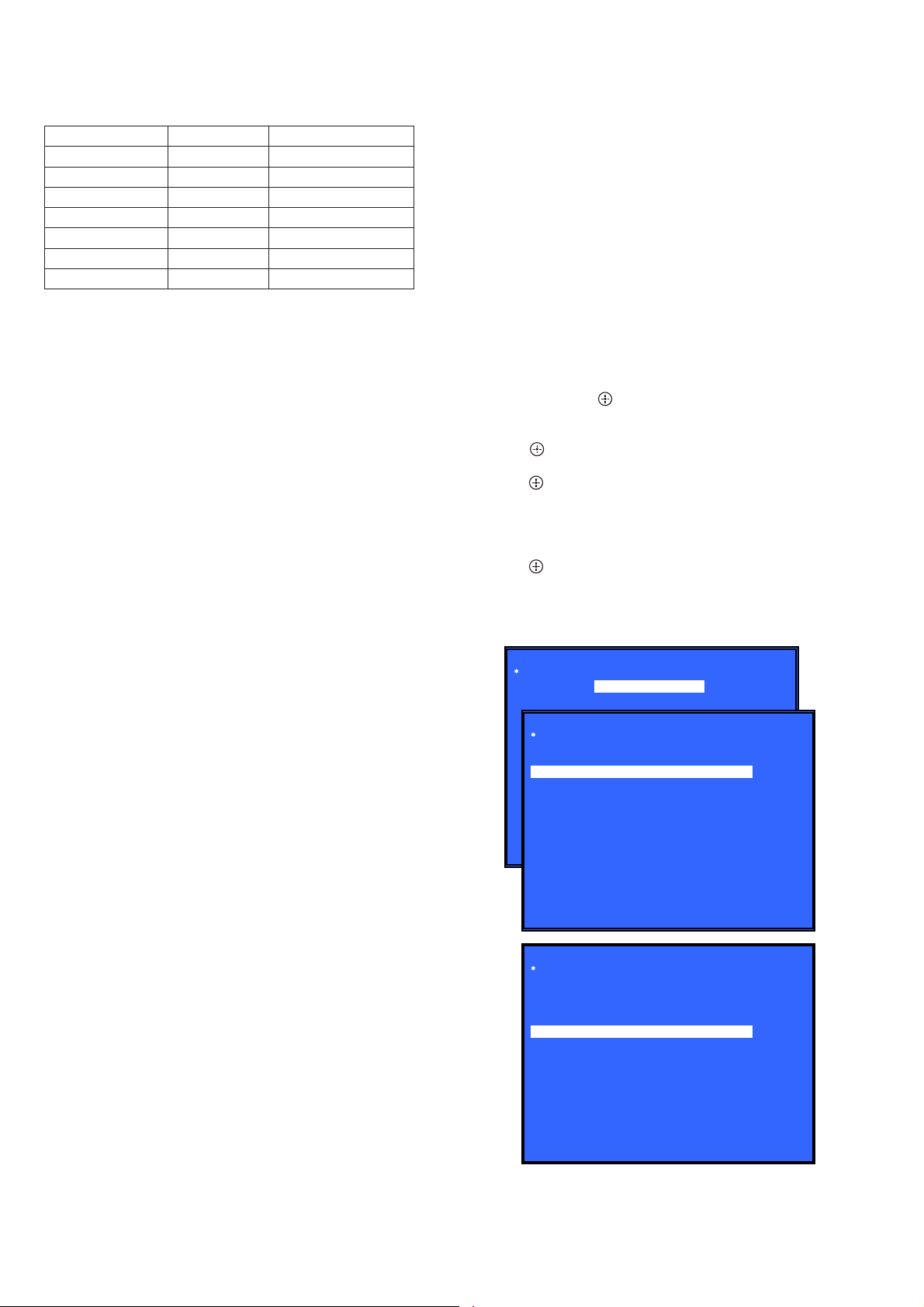
6. Press the [,] button on the remote commander to select
“Bluetooth Device Test”. (Screen 1)
7. Press the [ ] button on the remote commander to select “(1)
Bluetooth Enable”.
8. Press the [ ] button on the remote commander, wait until the
display show “Status: Bluetooth Enable Successful!” (Screen
2).
9. Press the [m] button on the remote commander to select “(3)
Write Bluetooth device address to Registry”.
10. Press the [ ] button on the remote commander, wait until the
display show “Status: Write Successful!” (Screen 3).
(Displayed characters/values in the following fi gure are ex-
ample)
11. Press the [
(Screen 1)
(Screen 2)
] button to turn the power off.
?/1
Diag
Category: Bluetooth Device Test
Diag
Category: Bluetooth Device Test
(1) Bluetooth Enable
(2) Bluetooth Disable
(3) Write Bluetooth device address to Registry
(4) Bluetooth Inquiry Test
Status: Bluetooth Enable Successful!
HELP: [UP] [DOWN] [ENT] [RET]
Diag
Category: Bluetooth Device Test
(1) Bluetooth Enable
(2) Bluetooth Disable
(3) Write Bluetooth device address to Registry
(4) Bluetooth Inquiry Test
Bluetooth Device address: A4:17:31:77:7E:7
Status: Write Successful!
(Screen 3)
HELP: [UP] [DOWN] [ENT] [RET]
6

HBD-N7100W/N7100WL/N8100W/N9100W/N9100WL/N9150W/N9150WL/N9900SH
NOTE OF REPLACING THE OPTICAL PICK-UP (KEM480AHA) (OP1) AND THE COMPLETE MB1004 BOARD
The password will be supplied to only service HQ, and
service center name, q’ty and all of software registered
information should be maintained by service HQ, and
Audio will ask to report the registration information.
Optical pick-up (KEM-480AHA) (OP1) for BD requires precise
read out functions and secure contents protection system for more
than past DVD/CD.
Therefore, in the case repaired as follows, the writing work of the
OP data is necessary.
• When the optical pick-up (KEM-480AHA) (OP1) is replaced
(The complete MB1004 board doesn’t replace).
• When both the optical pick-up (KEM-480AHA) (OP1) and
complete MB1004 board are replaced.
• When the complete MB1004 board is replaced (The optical
pick-up (KEM-480AHA) (OP1) doesn’t replace)
(In this case, do the work of “3. Optical pick-up (KEM-
480AHA) (OP1) replacement” other than the replacement of
new optical pick-up).
Note: The servo adjustment is done while writing the OP data. The manual
adjustment is unnecessary.
LD ON TIME history doesn’t carry over.
Do not touch any optical block parts, turn table and during replac-
ing. BD laser diode is very sensitive.
1. Preparation
1-1. ESD Countermeasure
It is necessary to confi rm the state of static electricity in the work
space before the repair is started.
The static electricity resistance of the BD laser is weaker than that
of the DVD/CD laser.
Do work space and worker’s ESD countermeasures to prevent destruction by ESD.
1-2. Jig
• Digital camera (Recommend with macro mode)
• USB memory
• PC
• Barcode decoder (Refer to “1-3. Barcode decoder
(BDPRdec)”)
1-3. Barcode decoder (BDPRdec)
Jig name: BDPRdec.exe
Software contents:
• BDPRdec.exe : Barcode decoder software
• SavePath.ini : Decoded fi le destination setting fi le (Ini-
tial destination is “C:\BuData.txt”)
• TasmanBars.dll : Decode dll
• Uninst.exe : Uninstall the “BDPRdec.exe” from PC
Note: When working by OS of the version after VISTA, it is necessary
to change destination of the decoded fi le to save by UAC function
(user account function).
In that case, change the description in “SavePath.ini” (default de-
scription is “C:\BuData.txt”) other than C drive.
Install procedure:
1. Unzip the barcode decoder fi les to any PC folder.
2. Check the attached 2D code photo (OK_sample.JPG) drag &
drop onto “BDBUDec.exe”.
When the barcode decoder is used for the fi rst time, the pass-
word is necessary. It is unnecessary since the second times.
Note 1: The password will be supplied to only service headquarters, and
service center name/q’ty/all of software registered information
should be maintained by service headquarters.
Note 2: Do not change the decoded fi le name “BuData.txt”.
3. When “.NET frame work requirements” is displayed, down-
load following applications from Microsoft download site.
• Microsoft .NET Framework Version 2.0 Redistributable Pack-
age (x86)
http://www.microsoft.com/downloads/details.aspx?displaylan
g=en&FamilyID=0856eacb-4362-4b0d-8edd-aab15c5e04f5
• Microsoft .NET Framework 2.0 Service Pack 1 (x86)
http://www.microsoft.com/downloads/details.aspx?displaylan
g=en&FamilyID=79bc3b77-e02c-4ad3-aacf-a7633f706ba5
How to use:
Case 1 Drag & drop 2D code photo onto “BDPRdec.exe”.
Case 2 Drag & drop BU data fi le onto “BDPRdec.exe”.
Data fi le name be changed to specify format and end of
7 character are defi ned.
You can also enter the fi le path at the prompt.
7

HBD-N7100W/N7100WL/N8100W/N9100W/N9100WL/N9150W/N9150WL/N9900SH
2. Pass-fail judgment of the optical pick-up (KEM-480AHA) (OP1)
Perform pass-fail judgment to judge whether the repair of the optical pick-up (KEM-480AHA) (OP1) is necessary.
2-1. Flow of drive section check
Confirm whether
BD (BLX-104) can be
reproduced
YES
NO
Confirm whether the
drive voltage is the
CN5301 pin 6 : 12 V
NO
following values
YES
Confirm F5301,
F5303, F5305 on
the MB1004 board,
and replace it
when it has been
damaged
Confirm OP FFC cable
(Part No. 1-846-669-11)
and SPD FFC cable
(Part No. 1-828-312-61),
and replace it when it
has been damaged
Then, confirm whether
this unit operates
normally
YES
OK
Confirm whether
DVD (HLX-513)/
CD (HLX-A1) can be
reproduced
Note: Refer to “2-6. OPTICAL PICK-UP BLOCK” on page 18 about how to remove the OPTICAL PICK-UP BLOCK.
NO
NO NO
Confirm whether
the optical pick-up
IOP is normal in the
service mode
(Refer to “2-2. Flow
of optical pick-up
IOP check”)
2-2. Flow of optical pick-up block IOP check
Turn the power on,
and change function
to “BD/DVD”
Press the buttons on
the remote commander
in order of [DISPLAY],
[0], [2], [1] [SUBTITLE],
and enter the service
mode
Confirm whether
value is the
specification value
Specification value:
BD : ±6 mA
DVD/CD: ±9 mA
YES
OK
NO
Repalece the
optical pick-up
(Refer to “3. Optical
pick-up (KEM-480AHA)
(OP1) replacement”)
Repalece the
optical pick-up
(KEM-480AHA) (OP1)
(Refer to “3. Optical
pick-up (KEM-480AHA)
(OP1) replacement”)
Press the buttons on
the remote commander
in order of [8], [7], [3],
[ ], and the
dIOP value is displayed
8
HBD-N7100W/N7100WL/N8100W/N9100W/N9100WL/N9150W/N9150WL/N9900SH
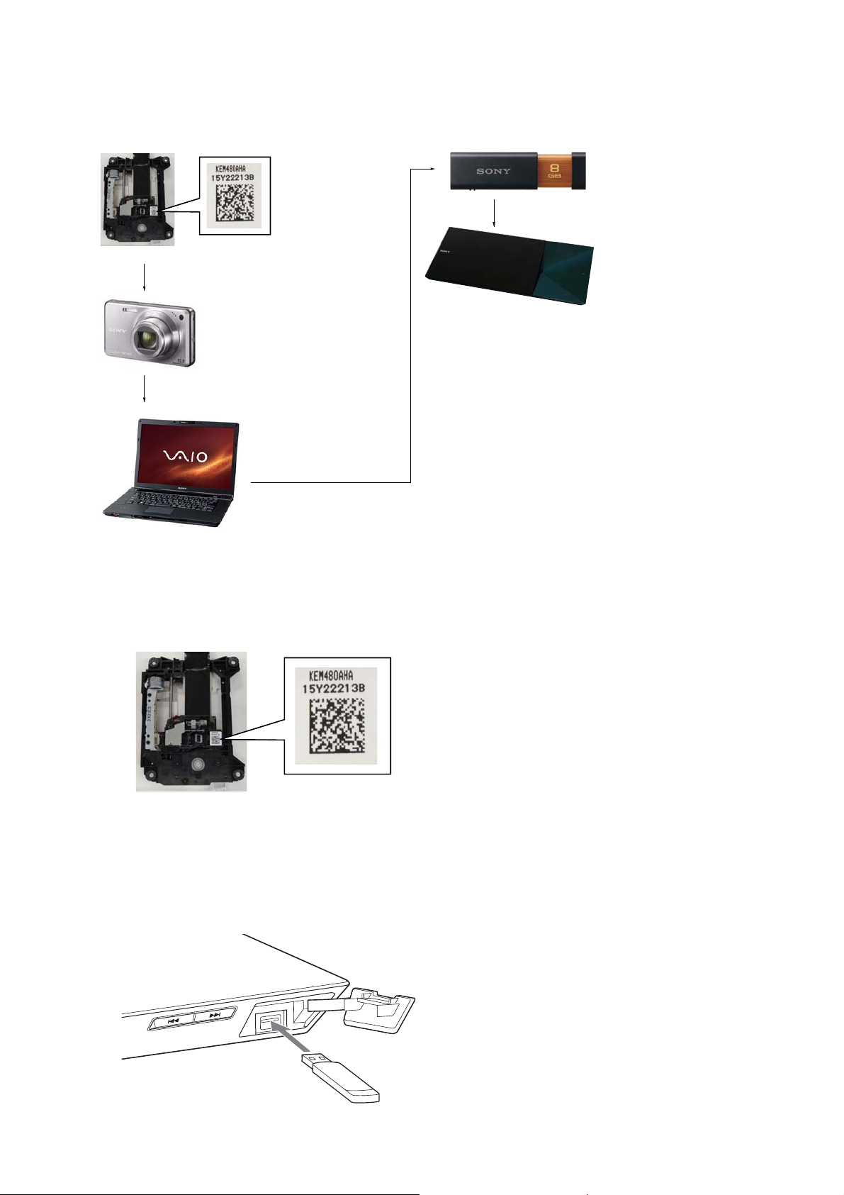
3. Optical pick-up (KEM-480AHA) (OP1) replacement
Flow of replacement:
Note: The photo in fl ow is an image.
Save the text data
Barcode label on
new optical pick-up
(KEM-480AHA)
(OP1) bottom side
Take photo (JPEG)
by digital camera
Change photo into
the text data with
the barcode decoder
to USB memory
(memory capacity
need not be 8GB)
Connect USB memory
with USB connector on
this unit, and read the text
data by the service mode
Procedure:
1. Remove the INSULATOR (4 pieces) and broken optical pickup (KEM-480AHA) (OP1) from LOADING ASSY (LOM1).
2. Take photo of the barcode on new optical pick-up (KEM480AHA) (OP1) bottom side by digital camera.
3. Assemble the INSULATOR (4 pieces) to new optical pick-up
(KEM-480AHA), fi x (Torque value: 2 kgf) it to LOADING
ASSY with screw, and assemble this unit.
4. Drag & drop the taken photo by step 2 to “BDPRDec.exe”, and
make the text data (File name: BuData.txt).
5. Save the text data to USB memory.
6. Connect USB memory with USB connector on this unit, and
turn the power on.
7. Press the [FUNCTION] button on the remote commander to
select “BD/DVD”.
8. Press the buttons on the remote commander in order of
[DISPLAY], [0], [2], [1], [SUBTITLE], and enter the service
mode.
9. Press the buttons on the remote commander in order of [8], [1],
[ENTER], and execute “[1] Drive OP data Write”.
10. Turn the power off after writing the OP data.
11. Turn the power on, and enter the service mode again.
12. Press the buttons on the remote commander in order of [8], [7],
[3], [ENTER], and the dIOP value is displayed.
13. Confi rm value is the following specifi cation value, and turn the
power off.
Specifi cation value:
BD : 6 mA
DVD/CD : 9 mA
14. Turn the power on, confi rm playback performance of the BD
(BLX-104)/DVD (HLX-513)/CD (HLX-A1).
15. Completely assemble this unit, and complete the repair.
– Front panel view –
9
HBD-N7100W/N7100WL/N8100W/N9100W/N9100WL/N9150W/N9150WL/N9900SH
Ver. 1.1
CHECKING METHOD OF NETWORK OPERATION
It is necessary to check the network operation, when replacing the
complete MB1004 board or WLAN/BT COMBO card (WBC1).
Check the operation of wireless and wired LAN, according to the
following method.
1. Checking Method of Wireless LAN Operation
Check that access point is recognized surely.
17. Press the [m]/[M] buttons on the remote commander to select
“IPv6”, and press the [
] button on the remote commander.
18. Press the [<]/[,] buttons on the remote commander to
select “Start”, and press the [ ] button on the remote commander.
19. Confi rm that “Network connections are correct” is displayed.
20. Press the [
Note: Refer to the instruction manual about details of the setting method.
] button to turn the power off.
?/1
Necessary Equipment:
Wireless access point with router function (AP).
Procedure:
1. Press the [
] button to turn the power on.
?/1
2. Press the [HOME] button on the remote commander to enter
the home menu.
3. Press the [m]/[M]/[<]/[,] buttons on the remote commander to select “Setup”“Network Settings”, and press the [ ]
button on the remote commander.
4. Select “Internet Settings”, and press the [ ] button on the remote commander.
5. Press the [m]/[M] buttons on the remote commander to select
“Wireless Setup (built-in)”, and press the [ ] button on the
remote commander.
6. The system starts searching for access points, and displays a
list of up available network name (SSID).
7. Check that access point (SSID) is displayed on the searching
result.
8. Press the [
Note: Refer to the instruction manual about details of the setting method.
] button to turn the power off.
?/1
2. Checking method of wired LAN operation
Check that access point is recognized surely.
Procedure:
1. Connect the main unit to the router or the hub, etc. with the
LAN cable.
2. Press the [
] button to turn the power on.
?/1
3. Press the [HOME] button on the remote commander to enter
the home menu.
4. Press the [m]/[M]/[<]/[,] buttons on the remote commander to select “Setup”“Network Settings”, and press the [
button on the remote commander.
5. Select “Internet Settings”, and press the [ ] button on the remote commander.
6. Press the [m]/[M] buttons on the remote commander to select
“Wired Setup”, and press the [ ] button on the remote commander.
7. Press the [m]/[M] buttons on the remote commander to select
“Auto”, and press the [ ] button on the remote commander.
8. Press the [,] button on the remote commander.
9. Press the [m]/[M] buttons on the remote commander to select
“Save & Connect”, and press the [ ] button on the remote
commander.
10. When “Internet Settings is now complete.” appears, then press
the [ ] button on the remote commander.
11. Press the [m]/[M] buttons on the remote commander to select
“Network Connection Diagnostics”, and press the [ ] button
on the remote commander.
12. Press the [m]/[M] buttons on the remote commander to select
“IPv4”, and press the [ ] button on the remote commander.
13. Press the [<]/[,] buttons on the remote commander to
select “Start”, and press the [ ] button on the remote commander.
14. Confi rm that “Network connections are correct” is displayed.
(When having confi rmed that “Network connections are cor-
rect” is displayed, advance to the step 20)
15. Press the [ ] button on the remote commander.
16. Press the [m]/[M] buttons on the remote commander to select
“Network Connection Diagnostics”, and press the [ ] button
on the remote commander.
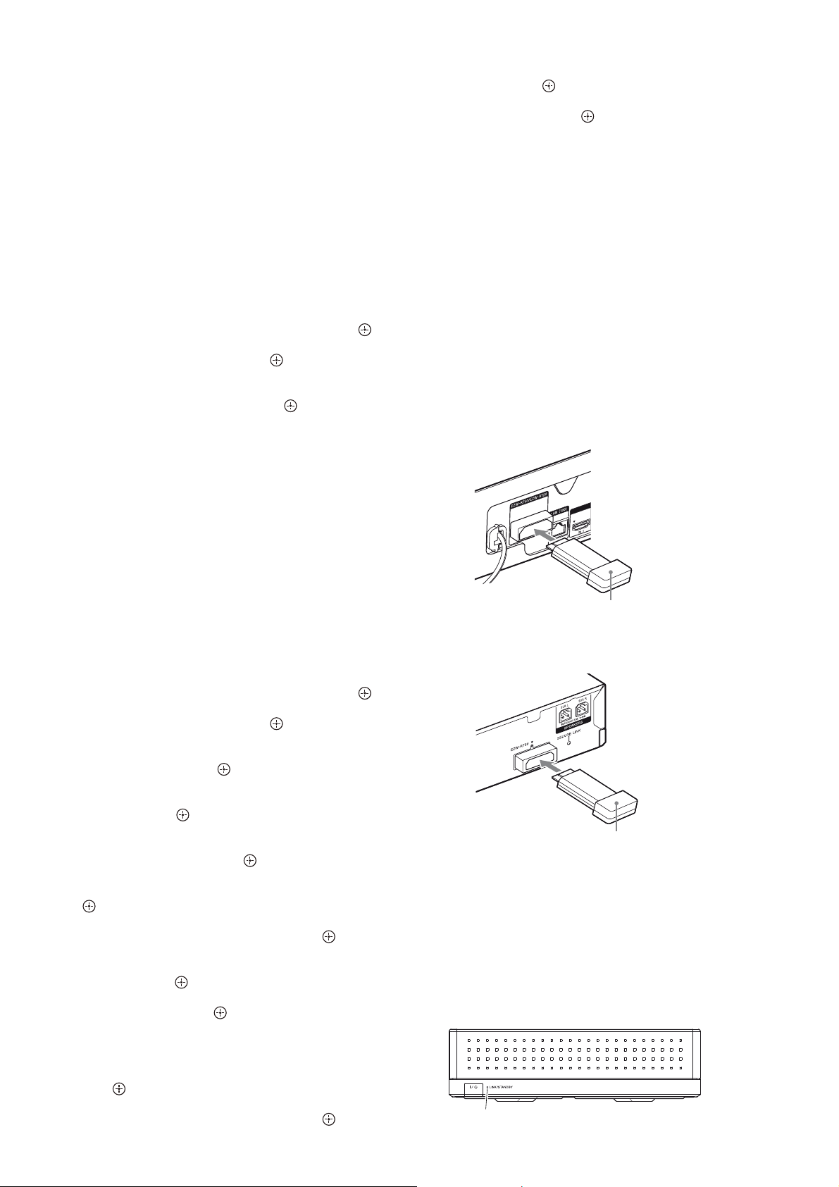
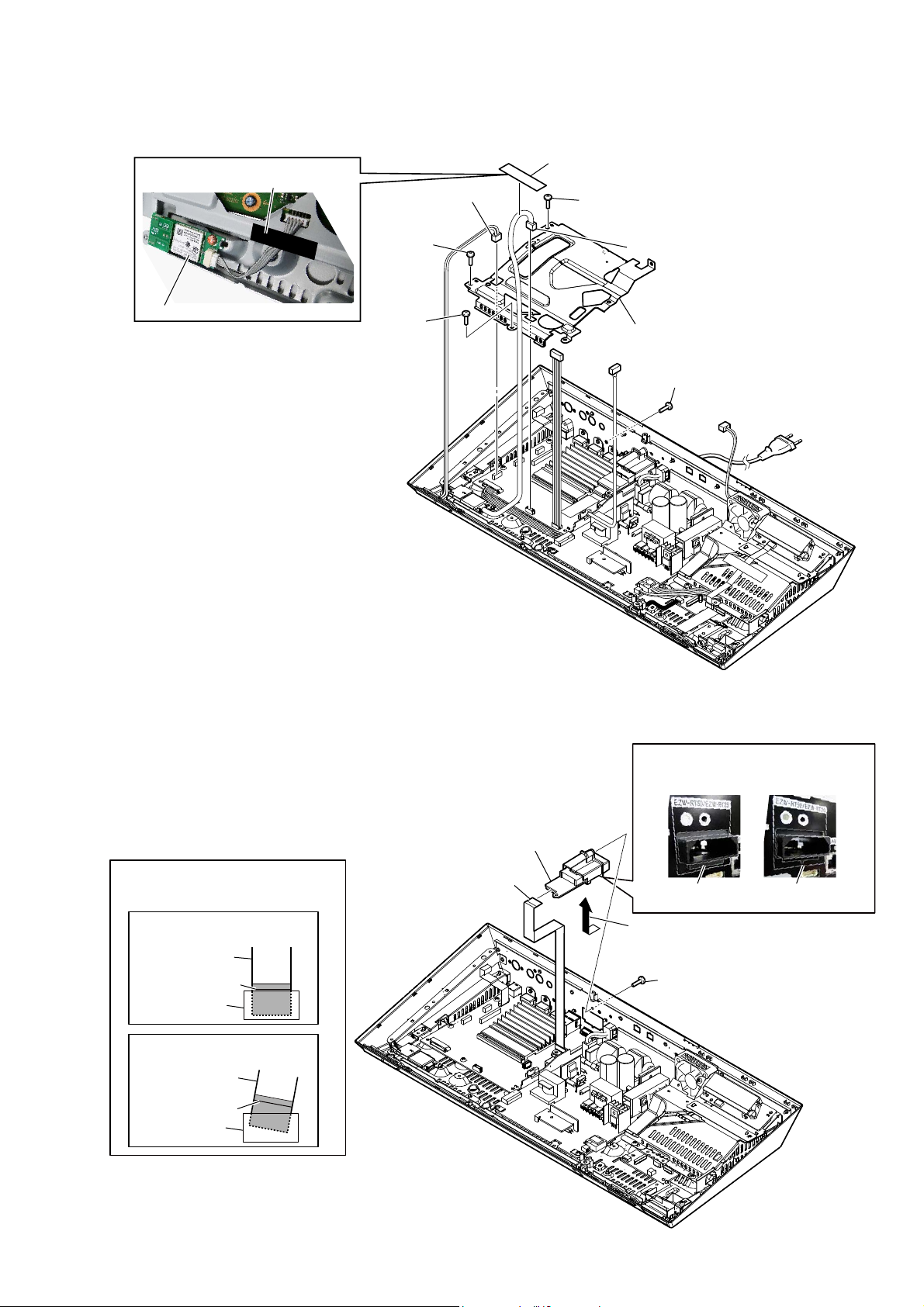
INSTALLATION METHOD OF THE WIRELESS SOUND
SYSTEM
Note:
EZW-RT20 : Wireless transceiver for Chinese model
EZW-RT50 : Wireless transceiver for except Chinese model
TA-SA300WR : Surround amplifi er for HBD-N7100W/N8100W/N9100W/
TA-SA400WR : Surround amplifi er for HBD-N7100WL/N9100WL/N9150WL/
N9150W
N9900SH
Procedure:
1. Insert the wireless transceiver (EZW-RT50 or EZW-RT20) of
the attachment in the wireless transceiver slot in the back of
the main unit and the surround amplifi er (TA-SA300WR or
TA-SA400WR).
Rear panel of the main unit
Wireless transceiver
(EZW-RT50 or EZW-RT20)
Rear panel of the surround amplifier
(TA-SA300WR or TA-SA400WR)
]
Wireless transceiver
(EZW-RT50 or EZW-RT20)
2. Connect the AC power cord of the main unit.
3. Press the [
] button on the main unit to turn the power on.
\/1
4. Connect the AC power cord of the surround amplifi er (TA-
SA300WR or TA-SA400WR).
5. When wireless transmission is activated, the [LINK/STANDBY] indicator of the surround amplifi er (TA-SA300WR or TA-
SA400WR) turns green.
Note: Refer to the operating instructions when the [LINK/STAND-
BY] indicator of the surround amplifi er (TA-SA300WR or TA-
SA400WR) doesn’t light.
– Front view –
LINK/STANDBY indicator
10

HBD-N7100W/N7100WL/N8100W/N9100W/N9100WL/N9150W/N9150WL/N9900SH
HOW TO EJECT THE DISC WHEN POWER SWITCH TURN OFF
3 Open the cover top assy.
1 plate (BD-H)
2 Insert a screwdriver and
turn the cam gear in the
direction of an arrow.
– Bottom view –
MD ASSY SERVICE POSITION
MD assy
cam gear
MB1004 board
11
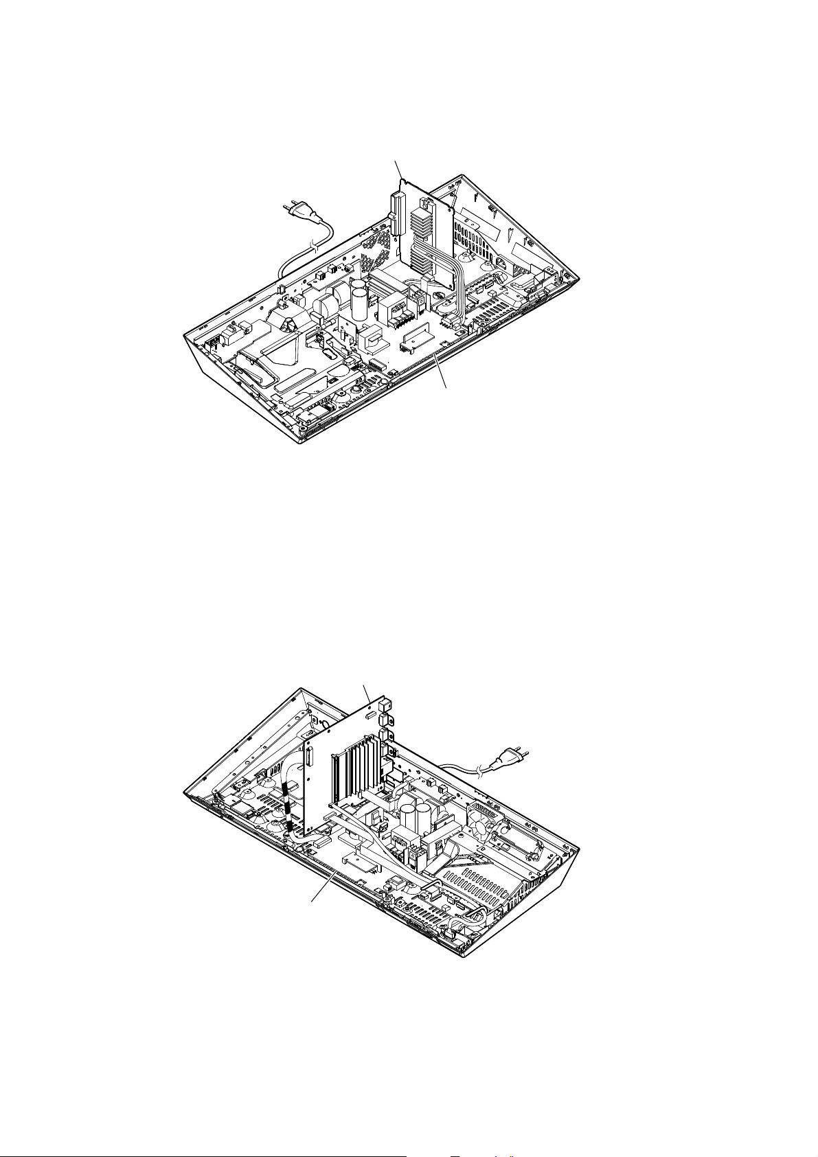
HBD-N7100W/N7100WL/N8100W/N9100W/N9100WL/N9150W/N9150WL/N9900SH
NJ_AMP BOARD SERVICE POSITION
NJ_AMP board
switching regulator
(SWR1)
MB1004 BOARD SERVICE POSITION
MB1004 board
switching regulator
(SWR1)
12

HBD-N7100W/N7100WL/N8100W/N9100W/N9100WL/N9150W/N9150WL/N9900SH
SECTION 2
DISASSEMBLY
• This set can be disassembled in the order shown below.
2-1. DISASSEMBLY FLOW
SET
2-2. COVER TOP ASSY
(Page 14)
2-3. INNER DOOR BLOCK
(Page 15)
2-4. BU TOP COVER BLOCK
(Page 16)
2-5. LOADING BASE BLOCK
(Page 17)
2-11. WLAN/BT COMBO
CARD (WBC1)
(Page 22)
2-6. OPTICAL PICK-UP BLOCK
(Page 18)
2-7. FLEXIBLE FLAT CABLE
(45 CORE) (FFC1),
WIRE (FLAT TYPE)
(9 CORE) (FFC2),
WIRE (FLAT TYPE)
(5 CORE) (FFC3)
(Page 19)
2-24. HOW TO BEND WIRE (FLAT TYPE)
(Page 30)
2-9. TOUCH-F BOARD BLOCK
(Page 20)
2-10. COVER (BOTTOM)
BLOCK
(Page 21)
2-12. FAN-LED BOARD
(Page 22)
2-13. TUNER-IO BOARD
(Page 23)
2-16. SHIELD (MB) BLOCK
(Page 25)
2-17. WS BOARD BLOCK
(Page 25)
2-22. MB1004 BOARD
(Page 28)
2-8. OPTICAL PICK-UP
(KEM-480AHA) (OP1)
(Page 20)
2-18. DC FAN (M1)
(Page 26)
2-15. SHIELD (POWER) BLOCK
(Page 24)
2-19. POWER CORD (AC1)
(Page 26)
2-20. SWITCHING REGULATOR (SWR1),
INSULATOR (BOTTOM)
(Page 27)
2-14. FL BOARD
(Page 23)
2-21. SHIELD (AMP)
BLOCK
(Page 27)
2-23. NJ_AMP BOARD
(Page 29)
13

HBD-N7100W/N7100WL/N8100W/N9100W/N9100WL/N9150W/N9150WL/N9900SH
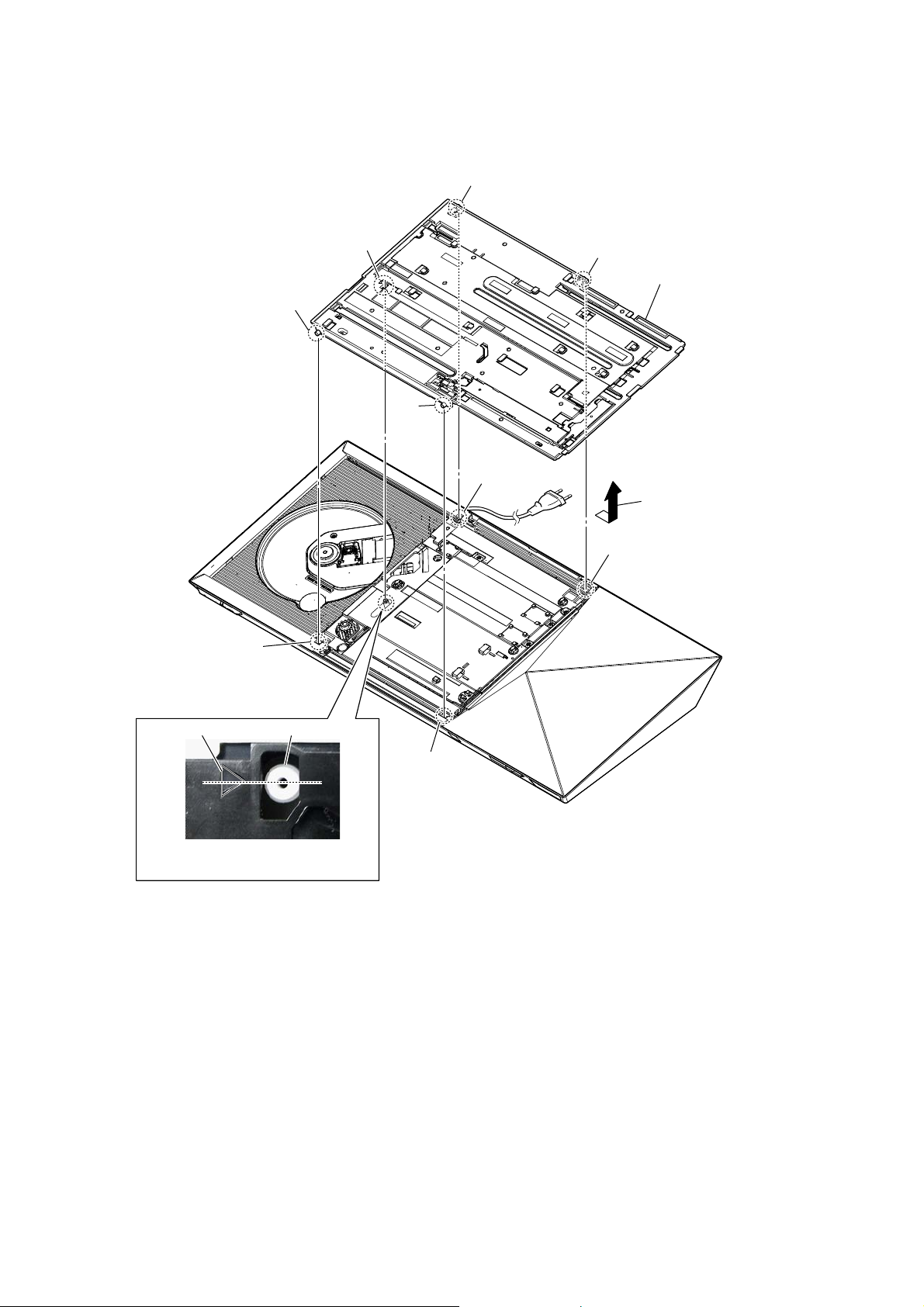
Note: Follow the disassembly procedure in the numerical order given.
2-2. COVER TOP ASSY
3 Open the cover top assy fully.
When installing the plate (BD-H),
Note:
check the installation orientation.
plate (BD-H)
front side
slot
2 Insert a screwdriver and
turn the cam gear in the
direction of an arrow.
1 plate (BD-H)
– Bottom view –
6 Remove the cover top assy
in the direction of an arrow.
4 screw
(PTP2 u 5)
8 cover top assy
cam gear
7 total fourteen claws
14
– Bottom view –
5 Close the inner door block little.
HBD-N7100W/N7100WL/N8100W/N9100W/N9100WL/N9150W/N9150WL/N9900SH
2-3. INNER DOOR BLOCK
shaft
ditch
shaft
marking
shaft
ditch
shaft
ditch
2
inner door block
1
Remove the inner door block
in the direction of an arrow.
Note 1:
door block, align four shafts
to four ditches.
When installing the inner
marking shaft
When installing the inner door block,
Note 2:
align the marking to the shaft.
ditch
15
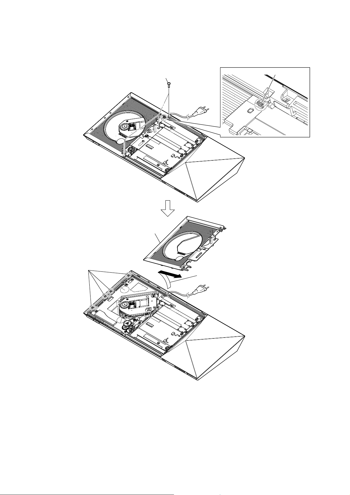
HBD-N7100W/N7100WL/N8100W/N9100W/N9100WL/N9150W/N9150WL/N9900SH
2-4. BU TOP COVER BLOCK
1 four screws
(BV DIA. 2.6 u 8)
5
BU top cover block
2
claw
4
four claws
3
Remove the BU top cover block
in the direction of an arrow.
16

HBD-N7100W/N7100WL/N8100W/N9100W/N9100WL/N9150W/N9150WL/N9900SH
2-5. LOADING BASE BLOCK
2 three screws
(BV3)
2 two screws
(BV3)
1 screw
(BV DIA. 2.6 u 8)
6 flexible flat cable (9 core)
(CN1260)
7 flexible flat cable (5 core)
(CN1270)
4
four claws
8
loading base block
5 flexible flat cable (45 core)
(CN1101)
When installing the flexible flat cable,
Note:
ensure the colored line.
No slanting after insertion.
Inserting is straight to the interior.
flexible flat cable
colored line
connector
Inserting is slant.
flexible flat cable
colored line
connector
3
Remove the loading base block
in the direction of an arrow.
OK
NG
17

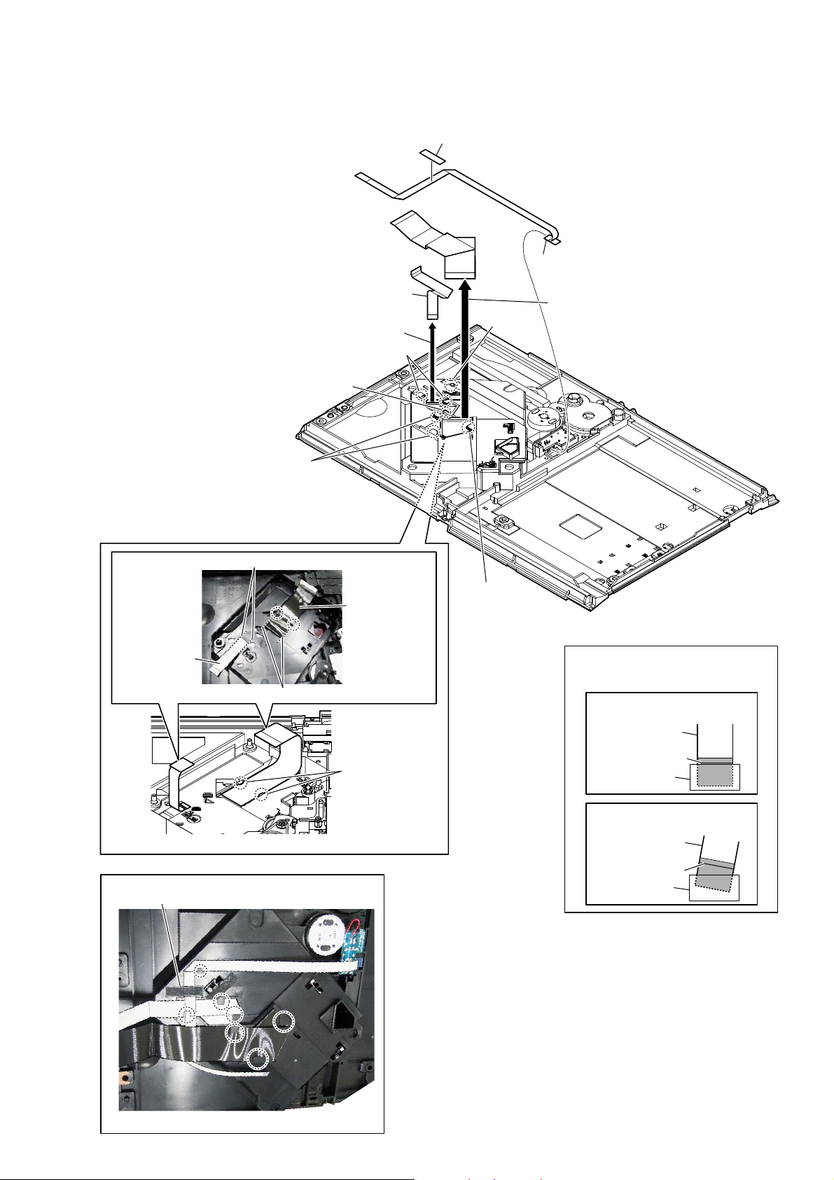
HBD-N7100W/N7100WL/N8100W/N9100W/N9100WL/N9150W/N9150WL/N9900SH
2-6. OPTICAL PICK-UP BLOCK
Make sure that the OP cover, OP cushion
Note 3:
and connector are hidden.
connector
1
Note 1:
two float
4
5 Remove the
pick-up block in the
direction of an arrow.
wire (flat type)
6
(9 core)
screws (S)
optical
OP sheet
OP sheet is not reused.
OP cover
two float
4
optical pick-up block
7
OP cushion
2
Note 5:
flexible flat cable (45 core)
3
OP cushion
guide line (concave edge)
screws (S)
OP cushion is not reused.
Make sure that flexible
Note 4:
flat cable is not bent.
OP sheet
Make sure that it is
Note 2:
not float or bent.
Make sure that the support
Note 6:
board is hidden.
OP cushion
OP cushion
OK
NG
18
When installing the flexible flat cable,
Note 7:
No slanting after insertion.
Inserting is straight to the interior. Inserting is slant.
flexible flat cable flexible flat cable
OK
colored line
ensure the colored line.
NG
colored line
connectorconnector
support board
(blue color portion)
OP cushion
support board
(blue color portion)
HBD-N7100W/N7100WL/N8100W/N9100W/N9100WL/N9150W/N9150WL/N9900SH
2-7. FLEXIBLE FLAT CABLE (45 CORE) (FFC1), WIRE (FLAT TYPE) (9 CORE) (FFC2), WIRE (FLAT TYPE) (5 CORE) (FFC3)
1 non halogene tape
:iUe setting
wire (flat type)
(9 core) (FFC2)
7 wire (flat type)
(FFC2)
6 Draw out the wire (flat type)
4 two claws
5 claw
9 two claws
No slanting
flexible flat cable
(45 core) (FFC1)
No slanting
(9 core)
(9 core)
2 claw
0 claw
3 wire (flat type)
(FFC3)
qa Draw out the flexible flat cable
Note:
ensure the colored line.
No slanting after insertion.
(5 core)
– Loading base block bottom view –
When installing the flexible flat cable,
OK
Inserting is straight to the interior.
flexible flat cable
(45 core)
– Loading base block top view –
:iUe setting
non halogene tape
– Loading base block bottom view –
8 two claws
colored line
connector
NG
Inserting is slant.
flexible flat cable
colored line
connector
19

HBD-N7100W/N7100WL/N8100W/N9100W/N9100WL/N9150W/N9150WL/N9900SH
2-8. OPTICAL PICK-UP (KEM-480AHA) (OP1)
Note: When the optical pick-up (KEM-480AHA) (OP1) is replaced, refer to
“NOTE OF REPLACING THE OPTICAL PICK-UP (KEM-480AHA)
(OP1) AND THE COMPLETE MB1004 BOARD on page 7.
1 two screws
(0 + Z P1.7 u 5)
2 BU cover block
3 three claws
5 insulator
1 two screws
(0 + Z P1.7 u 5)
4 OP cover
3 two claws
5 insulator
5 insulator
6 optical pick-up
(KEM-480AHA)
(OP1)
5 insulator
2-9. TOUCH-F BOARD BLOCK
Note 1: When TOUCH-F board is defective,
exchange the complete mounted board.
7 TOUCH-F board block
3 claw
2 Remove the TOUCH-F board block
in the direction of an arrow.
5 three claws
4 three claws
6 wire (flat type) (20 core)
(CN154)
When installing the wire (flat type),
Note 2:
ensure the colored line.
No slanting after insertion.
Inserting is straight to the interior.
wire (flat type)
wire (flat type)
OK
colored line
connector
NG
Inserting is slant.
20
1 two screws
(BV DIA. 2.6 u 8)
colored line
connector
HBD-N7100W/N7100WL/N8100W/N9100W/N9100WL/N9150W/N9150WL/N9900SH
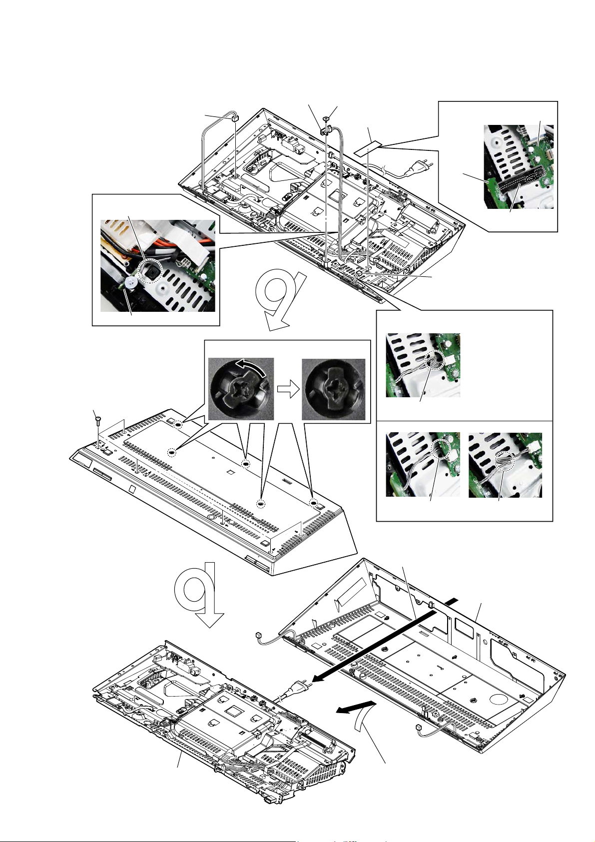
2-10. COVER (BOTTOM) BLOCK
:LUHVHWWLQJ
Avoid the screw hole.
Note:
SIRCS board
5 connector
(CN6301)
4 SIRCS board
7 Unlock five locks (bottom)
3 float screw (S)
1 fabric non woven
(15T25)
:LUHVHWWLQJ
:LUHVHWWLQJ
CHUKEI board
AMS_KEY
board
fabric non woven
(15T25)
2 connector (CN153)
OK
6 six screws
(BV3)
–BRWWRPYLHZ–
Fold at the CHUKEI
board side
NG NG
Fold at center positionUnder the CHUKEI
board
9 Draw out the power cord
cover (bottom) block
0
chassis block
8 Remove the chassis block
in the direction of an arrow.
21

HBD-N7100W/N7100WL/N8100W/N9100W/N9100WL/N9150W/N9150WL/N9900SH
Ver. 1.1
2-11. WLAN/BT COMBO CARD (WBC1)
Note: When the WLAN/BT combo card (WBC1) is replaced, “NOTE OF REPLACING THE
WLAN/BT COMBO CARD (WBC1) AND THE COMPLETE MB1004 BOARD” on
page 6 and “CHECKING METHOD OF NETWORK OPERATION” on page 10.
2 screw (BV3)
WLAN/BT combo card
6
(WBC1)
3 Remove the WLAN/BT combo card
in the direction of an arrow.
5 connector
4 two claws
:LUHVHWWLQJ
fabric non woven (15T25)
1 fabric non woven
(15T25)
WLAN/BT combo card (WBC1)
2-12. FAN-LED BOARD
4 connector
(CN105 (N7100W/N8100W/N9100W/N9150W),
CN101 (N7100WL/N9100WL/N9150WL/N9900SH))
1 two screws
(BV3)
5 FAN-LED board
3 connector
(CN102)
2 Remove the FAN-LED board
in the direction of an arrow.
:LUHVHWWLQJ
Twist the wire at 1 turn clockwise.
FAN-LED board
22

HBD-N7100W/N7100WL/N8100W/N9100W/N9100WL/N9150W/N9150WL/N9900SH
2-13. TUNER-IO BOARD
3 wire (flat type) (11 core)
(CN2003)
4 TUNER-IO board
2 Remove the TUNER-IO board
in the direction of an arrow.
1 four screws (BV3)
2-14. FL BOARD
When installing the wire (flat type),
Note:
ensure the colored line.
No slanting after insertion.
Inserting is straight to the interior.
wire (flat type)
wire (flat type)
colored line
:LUHVHWWLQJ
OK
colored line
connector
NG
Inserting is slant.
connector
wire (flat type)
(7 core) FL board
OK NG
FL board
wire (flat type)
(7 core)
1 fabric non woven
(15T25)
2 screw
(BV3)
5 fabric non woven
(5T25)
2 screw
(BV3)
6 FL board
4 wire (flat type)
(7 core)
(CN900)
3
Remove the FL board
block in the direction
of an arrow.
fabric non woven
(15T25)
Not covering ventilation
holes.
fabric non woven
(15T25)
Covering ventilation
holes.
23

HBD-N7100W/N7100WL/N8100W/N9100W/N9100WL/N9150W/N9150WL/N9900SH
2-15. SHIELD (POWER) BLOCK
6 fabric non woven
(15T25)
:LUHVHWWLQJ
wire (flat type)
(30 core) (FFC7)
:LUHVHWWLQJ
clamp
2 wire (flat type)
(FFC7) (CN6303)
1 connector
(CN151)
OK
CHUKEI board
(30 core)
5 wire (flat type)
(7 core) (CN152)
NG
CHUKEI board
clamp
:LUHVHWWLQJ
DC fan (M1)
4 Remove wire from
clamp.
3 Remove wire from
wiring stopper.
7 connector
(CN601)
:LUHVHWWLQJ
OK
When installing the flexible flat cable,
Note:
ensure the colored line.
No slanting after insertion.
Inserting is straight to the interior.
flexible flat cable
flexible flat cable
:LUHVHWWLQJ
OK
wiring stopper
NG
OK
colored line
connector
NG
Inserting is slant.
colored line
connector
wiring stopper
NG
OK
MB1004 board
CN6303
NG
MB1004 board
CN6303
OK
processing area
NG NG
Wires arranged
side by side.
fabric non woven
(15T25)
Wires are not overlapped
on each other on top of
usb cable.
Wires arranged
overlapping.
FUSB board
0 two screws
(BV3)
shield (power)
qa
block
FUSB board
9 two screws
(BV3)
0 screw
(BV3)
0 screw
(BV3)
8 two screws
(BV3)
8 screw
(BV3)
Wires are overlapped
on each other on top
of usb cable.
24
Wires are sticking out
from processing area.
HBD-N7100W/N7100WL/N8100W/N9100W/N9100WL/N9150W/N9150WL/N9900SH
2-16. SHIELD (MB) BLOCK
:LUHVHWWLQJ
fabric non woven (15T25)
WLAN/BT combo card (WBC1)
3 connector (CN6301)
5 screw
(BV3)
5 screw
(BV3)
1 fabric non woven
(15T25)
5 screw (BV3)
2 connector (CN602)
shield (MB) block
6
4 screw (BV3)
2-17. WS BOARD BLOCK
When installing the wire (flat type),
Note 1:
ensure the colored line.
No slanting after insertion.
Inserting is straight to the interior.
wire (flat type)
wire (flat type)
colored line
OK
colored line
connector
NG
Inserting is slant.
connector
4 WS board block
3 wire (flat type)
(CN501)
(13 core)
When installing the WS board block,
Note 2:
check that the holder (WS) is outside.
OK NG
Holder (WS) is
outside.
2 Remove the WS board block
in the direction of an arrow.
1 screw
(BV3)
Holder (WS) is
inside.
25

HBD-N7100W/N7100WL/N8100W/N9100W/N9100WL/N9150W/N9150WL/N9900SH
2-18. DC FAN (M1)
When installing the DC fan (M1),
Note:
check that label side is the chassis side.
DC fan (M1)
2 DC fan (M1)
The label side is the chassis side.
1 two screws
(BV3)
2-19. POWER CORD (AC1)
3RZHUFRUGVHWWLQJ
power cord
push
1 power cord connector
switching regulator
(SWR1)
(CN1)
2 two claws
5 cord bushing
(FBS001)
4 claw
6 power cord (AC1)
3 Remove the cord bushing
(FBS001) in the direction
of an arrow.
&RUGEXVKLQJ)%6VHWWLQJ
When installing the cord bushing (FBS001),
Note:
mind the direction of claw at type No. mark
and align into the hole and press in fully.
50 + 5 mm
power cord
cord bushing
(FBS001)
type No.
FBS
001
claw
type No.
001
FBS
claw
cord bushing
(FBS001)
power cord
26

HBD-N7100W/N7100WL/N8100W/N9100W/N9100WL/N9150W/N9150WL/N9900SH
2-20. SWITCHING REGULATOR (SWR1), INSULATOR (BOTTOM)
4 two screws
WireVeWWiQJ
MB1004 board
push
push
push
3 connector
(CN301)
(BV3)
4 screw
(BV3)
6 insulator
(bottom)
1 connector
(CN101)
4 two screws
(BV3)
5 switching regulator
(SWR1)
WireVeWWiQJ
NJ_AMP board
switching regulator
(SWR1)
2-21. SHIELD (AMP) BLOCK
2 connector (CN4)
2 screw (BV3)
4 wiring stopper
3 clamp
2 screw (BV3)
2 screw (BV3)
switching regulator
(SWR1)
shield (AMP) block
5
heatsink (AMP)
1 three screws
(BV3)
27

HBD-N7100W/N7100WL/N8100W/N9100W/N9100WL/N9150W/N9150WL/N9900SH
2-22. MB1004 BOARD
Note 1: When the complete MB1004 board is replaced, refer to “NOTE OF REPLACING THE WLAN/BT COMBO CARD (WBC1) AND
Note 2:
cable, ensure the colored line.
No slanting after insertion.
THE COMPLETE MB1004 BOARD” on page 6, “NOTE OF REPLACING THE OPTICAL PICK-UP (KEM-480AHA) (OP1)
AND THE COMPLETE MB1004 BOARD on page 7 and “CHECKING METHOD OF NETWORK OPERATION” on page 10.
:LUHVHWWLQJ
CN601
When installing the flexible flat
Inserting is straight to the interior.
flexible flat cable
fabric non woven (15T25)
MB1004 board
OK
1 fabric non woven (15T25)
2 connector
(CN601)
3 wire (flat type)
(11 core) (FFC4)
(CN5910)
5 wire (flat type) (13 core)
(CN5909)
4 connector
(CN5301)
colored line
connector
NG
Inserting is slant.
flexible flat cable
colored line
connector
6 insulation sheet
(MB)
qa four screws
(BV3)
(US)
7 two screws
(BV3)
8 bracket (WS)
qs MB1004 board
0 three screws
(P3 u 3)
28
9 wire (flat type) (24 core)
(CN5905)

HBD-N7100W/N7100WL/N8100W/N9100W/N9100WL/N9150W/N9150WL/N9900SH
2-23. NJ_AMP BOARD
Note: When the complete NJ_AMP board is replaced, spread the compound referring
to “NOTE OF REPLACING THE IC3102 AND IC3302 ON THE NJ_AMP
BOARD AND THE COMPLETE NJ_AMP BOARD” on page 5.
1 wire (flat type) (24 core)
(CN3504)
5 two screws (BV3)
WireVHWWLQJ
switching regulator
(SWR1)
2 three screws
(transistor)
3 heatsink (AMP)
5 screw (BV3)
6 NJ_AMP board
5 screw (BV3)
NJ_AMP board
heatsink (AMP)
4 screw (BV3)
29

HBD-N7100W/N7100WL/N8100W/N9100W/N9100WL/N9150W/N9150WL/N9900SH
2-24. HOW TO BEND WIRE (FLAT TYPE)
: Mountain fold
: Valley fold
IOH[LEOHIODWFDEOHFRUHOHQJWKPP5HI1R))& ZLUHIODWW\SHFRUHOHQJWKPP5HI1R))&
15 mm
MB1004 board
(CN1101)
The lower side
is contact side.
ZLUHIODWW\SHFRUHOHQJWKPP5HI1R))&
130 mm
loading assy
The upper side is
terminal side.
106 mm
76 mm
optical pick-up
(KEM-480AHA)
The lower side
is contact side.
55 mm
The lower side
is contact side.
MB1004 board
(CN1260)
The lower side
is contact side.
optical pick-up
(KEM-480AHA)
60 mm
65 mm
MB1004 board
(CN1270)
The lower side
is contact side.
ZLUHIODWW\SHFRUHOHQJWKPP5HI1R))&
125 mm
MB1004 board
(CN6303)
The lower side
is contact side.
ZLUHIODWW\SHFRUHOHQJWKPP5HI1R))&
25 mm
TOUCH-F board
(CN701)
The lower side
is contact side.
ZLUHIODWW\SHFRUHOHQJWKPP5HI1R))& ZLUHIODWW\SHFRUHOHQJWKPP5HI1R))&
20 mm
19 mm
35 mm
The lower side
is contact side.
CHUKEI board
(CN151)
60 mm65 mm
The lower side
is contact side.
CHUKEI board
(CN154)
65 mm70 mm
TOUCH-F board
(CN702)
The upper side is
terminal side.
30
81 mm
The lower side
is contact side.
24 mm
LED board
(CN330)
NFC
(RC-S801)
(NFC1)
The upper side is
terminal side.
30 mm
60 mm
TOUCH-F board
(CN700)
 Loading...