

Sony GDM 5010PT Service Manual
GDM-5010PT
SERVICE MANUAL
SPECIFICATIONS
Picture tube 0.25 – 0.27 mm aperture grille pitch
21 inches measured diagonally
90-degree deflection
Viewable image size Approx. 403.8 × 302.2 mm (w/h)
(16 × 12
19.8” viewing image measured
diagonally
Resolution Horizontal: Max. 1600 dots
Vertical: Max. 1200 lines
Standard image area Approx. 388 × 291 mm (w/h)
Deflection frequency Horizontal: 30 to 96 kHz
AC input voltage/current
Power consumption Max. 160 W
Dimensions 500.3 × 502.5 × 476.5 mm (w/h/d)
Mass Approx. 31 kg (68 lb 5 oz)
3
(15
/
or
Approx. 364 × 291 mm (w/h)
3
(14
/
Vertical: 48 to 160 Hz
100 to 240 V, 50 – 60 Hz, 2.0 – 1.0 A
3
(19
/
N. Hemisphere Model
S. Hemisphere Model
Korea Model
Japan Model
Chassis No. SCC-L04F-A
inches)
8
× 11
8
× 11
4
× 19
1
/2 inches)
1
/2 inches)
7
/
8
× 18
7
/8 inches)
N3
CHASSIS
Design and specifications are subject to change without
notice.
COLOR GRAPHIC DISPLAY
GDM-5010PT
SAFETY CHECK-OUT
(US Model only)
After correcting the original service problem, perform the following safety checks before releasing the set to the customer:
1. Check the area of your repair for unsoldered or poorly-soldered connections. Check the entire board surface for solder
splashes and bridges.
2. Check the interboard wiring to ensure that no wires are
“pinched” or contact high-wattage resistors.
3. Check that all control knobs, shields, covers, ground straps,
and mounting hardware have been replaced. Be absolutely
certain that you have replaced all the insulators.
4. Look for unauthorized replacement parts, particularly transistors, that were installed during a previous repair. Point them
out to the customer and recommend their replacement.
5. Look for parts which, though functioning, show obvious signs
of deterioration. Point them out to the customer and recommend their replacement.
6. Check the line cords for cracks and abrasion. Recommend the
replacement of any such line cord to the customer.
7. Check the B+ and HV to see if they are specified values. Make
sure your instruments are accurate; be suspicious of your HV
meter if sets always have low HV.
8. Check the antenna terminals, metal trim, “metallized” knobs,
screws, and all other exposed metal parts for AC Leakage.
Check leakage as described below.
To Exposed Metal
Parts on Set
AC
0.15 µF
1.5 k
Ω
Earth Ground
Voltmeter
(0.75 V)
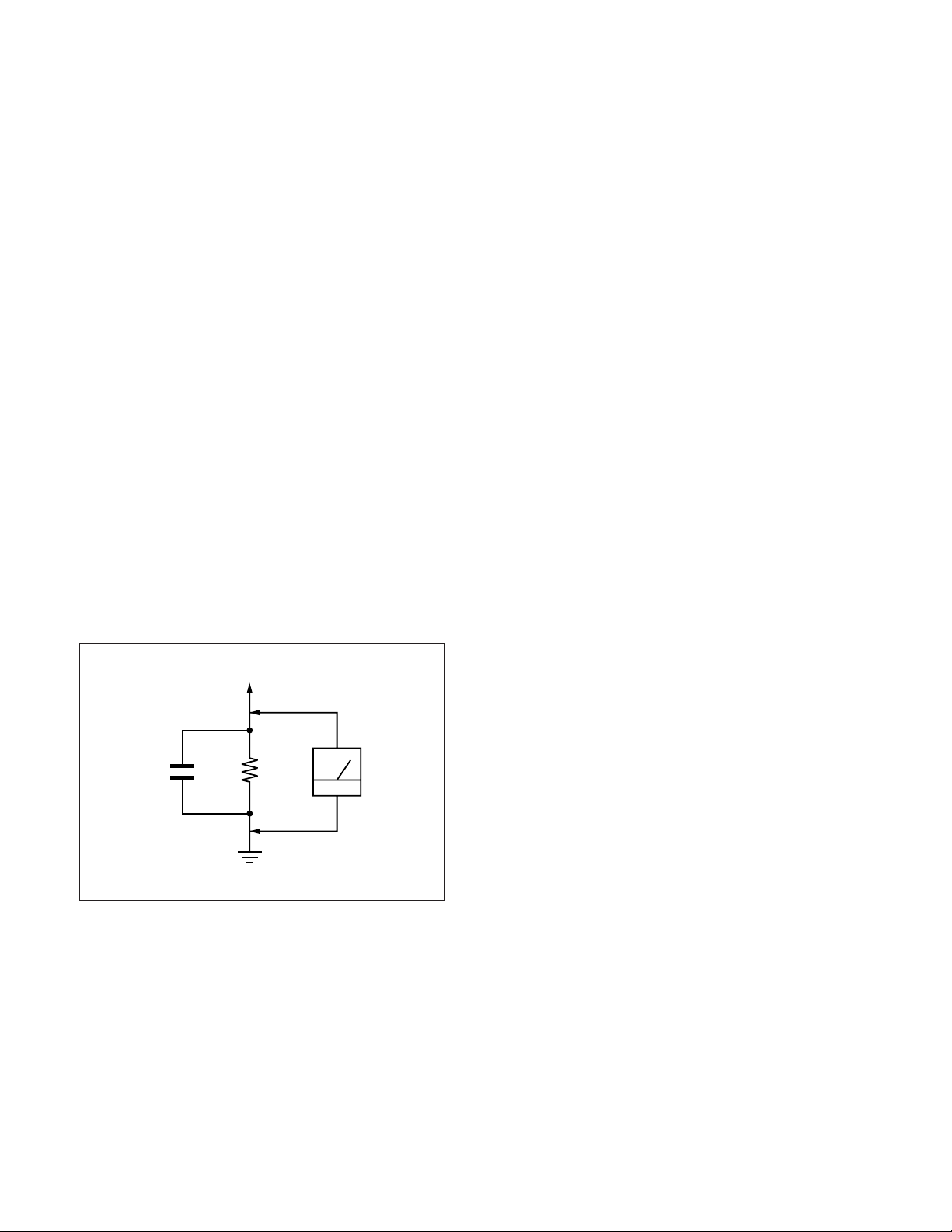
Fig. A. Using an AC voltmeter to check AC leakage.
LEAKAGE TEST
The AC leakage from any exposed metal part to earth ground
and from all exposed metal parts to any exposed metal part
having a return to chassis, must not exceed 0.5 mA (500
microampers).
Leakage current can be measured by any one of three methods.
1. A commercial leakage tester, such as the Simpson 229 or
RCA WT-540A. Follow the manufacturers’ instructions to
use these instruments.
2. A battery-operated AC milliammeter. The Data Precision 245
digital multimeter is suitable for this job.
3. Measuring the voltage drop across a resistor by means of a
VOM or battery-operated AC voltmeter. The “limit” indication is 0.75 V, so analog meters must have an accurate lowvoltage scale. The Simpson 250 and Sanwa SH-63Trd are examples of a passive VOMs that are suitable. Nearly all battery
operated digital multimeters that have a 2 V AC range are suitable. (See Fig. A)
WARNING!!
NEVER TURN ON THE POWER IN A CONDITION IN
WHICH THE DEGAUSS COIL HAS BEEN REMOVED.
SAFETY-RELATED COMPONENT WARNING!!
COMPONENTS IDENTIFIED BY SHADING AND MARK
¡ ON THE SCHEMATIC DIAGRAMS, EXPLODED
VIEWS AND IN THE PARTS LIST ARE CRITICAL FOR
SAFE OPERATION. REPLACE THESE COMPONENTS
WITH SONY PARTS WHOSE PART NUMBERS APPEAR AS SHOWN IN THIS MANUAL OR IN SUPPLEMENTS PUBLISHED BY SONY. CIRCUIT ADJUSTMENTS THAT ARE CRITICAL FOR SAFE OPERATION
ARE IDENTIFIED IN THIS MANUAL. FOLLOW THESE
PROCEDURES WHENEVER CRITICAL COMPONENTS ARE REPLACED OR IMPROPER OPERATION
IS SUSPECTED.
AVERTISSEMENT!!
NE JAMAIS METTRE SOUS TENSION QUAND LA
BOBINE DE DEMAGNETISATION EST ENLEVÉE.
ATTENTION AUX COMPOSANTS RELATIFS À LA
SÉCURITÉ!!
LES COMPOSANTS IDENTIFIÉS PAR UNE TRAME ET
UNE MARQUE
SÉCURITÉ. NE LES REMPLACER QUE PAR UNE PIÈCE
PORTANT LE NUMÉRO SPECIFIÉ. LES RÉGLAGES DE
CIRCUIT DONT L’IMPORTANCE EST CRITIQUE POUR
LA SÉCURITÉ DU FONCTIONNEMENT SONT
IDENTIFIÉS DANS LE PRÉSENT MANUEL. SUIVRE CES
PROCÉDURES LORS DE CHAQUE REMPLACEMENT
DE COMPOSANTS CRITIQUES, OU LORSQU’UN
MAUVAIS FONCTIONNE-MENT EST SUSPECTÉ.
– 2 –
¡ SONT CRITIQUES POUR LA
POWER SAVING FUNCTION
GDM-5010PT
This monitor meets the power-saving guidelines set by
VESA and Energy Star, as well as the more stringent
NUTEK .
In particular, the monitor is capable of entering a low power
state when it is inactive and used with an Energy Star
capable framebuffer and appropriate Sun system software.
You can set the delay time before the monitor enters the
power saving mode using the OSD. Set the time according
to “Setting the power saving delay time” on page 15.
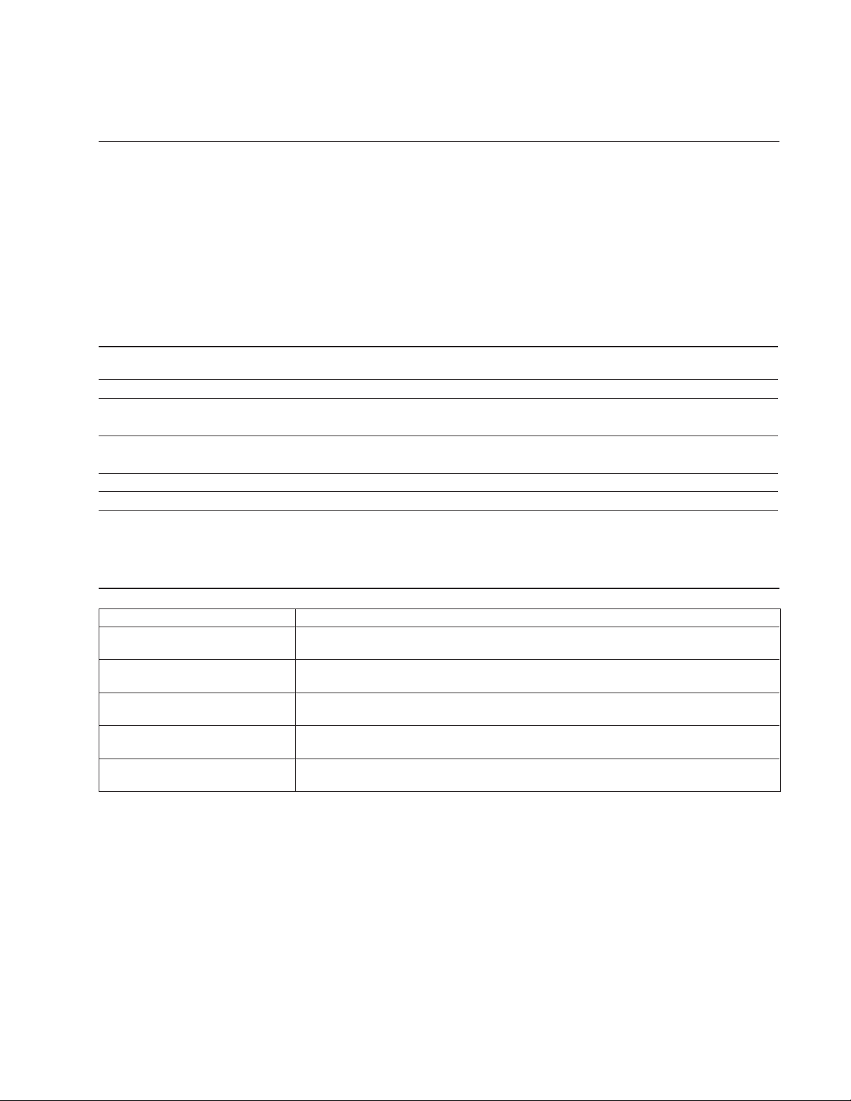
Power consumption
mode
Normal operation
1
Standby (1st mode)
2
Suspend (2nd mode)
3
Active-off (3rd mode)
4
Power-off
5
Screen
active
blank
blank
blank
—
Horizontal
sync signal
present
absent
present
absent
—
Note
If no video signal is input to the monitor, the “NO INPUT
SIGNAL” message (page 18) appears. After the delay time has
passed, the power saving function automatically puts the monitor
into the active-off mode and the u indicator lights up orange. Once
the horizontal and vertical sync signals are detected, the monitor
automatically resumes its normal operation mode.
Vertical
sync signal
present
present
absent
absent
—
Power
consumption
≤ 160 W
≤ 100 W
≤ 15 W
≤ 5 W
< 1.0 W
Recovery time
—
Approx. 3 sec.
Approx. 3 sec.
Approx. 10 sec.
—
u indicator
Green
Green and orange
alternate
Green and orange
alternate
Orange
Off
DIAGNOSIS
Failre
+B failure
Horizontal / Vertical Deflection failure,
Thermal protector
ABL protector
HV failure
Aging / Self Test
Yellow → Off
(0.5 sec) (0.5 sec)
Yellow → Off
(1.5 sec) (0.5 sec)
Yellow → Off
(0.5 sec) (1.5 sec)
Yellow → Off → Yellow → Off
(0.25 sec) (0.5 sec) (0.25 sec) (1.25 sec)
Yellow → Off → Green → Off
(0.5 sec) (0.5 sec) (0.5 sec) (0.5 sec)
Aging Mode (Video Aging) : During Power Save, press “MENU” key for longer than 2 second.
Self Test (OSD Color Bar) : During Power Save, press “CONTRAST” + (/) key for longer than 2 second.
Reliability Check Mode : During Power Save, press “CONTRAST” – (?) key for longer than 2 second.
Power LED
– 3 –
GDM-5010PT
TIMING SPECIFICATION
MODE AT PRODUCTION MODE 1 MODE 2
RESOLUTION 1280 X 1024 1152 X 900
CLOCK 135.000 MHZ 108.000 MHZ
-- HORIZONTAL -H-FREQ 81.130 kHz 71.809 kHz
usec usec
H. TOTAL 12.326 13.926
H. BLK 2.844 3.259
H. FP 0.237 0.296
H. SYNC 0.474 1.185
H. BP 2.133 1.778
H. ACTIV 9.481 10.667
-- VERTICAL -V. FREQ(HZ) 76.107 Hz 76.149 Hz
lines lines
V. TOTAL 1066 943
V. BLK 42 43
V. FP 2 2
V. SYNC 8 8
V. BP 32 33
V. ACTIV 1024 900
-- SYNC -INT(G) NO NO
EXT(H/V)/POLARITY NO NO
EXT(CS)/POLARITY YES N YES N
INT/NON INT NON INT NON INT
97.12.10 Ver.
– 4 –

TABLE OF CONTENTS
Section Title Page
1. GENERAL................................................................. 1-1
2. DISASSEMBLY
2-1. Rear Bucket Assy Removal ............................... 2-1
2-2. D Board Removal .............................................. 2-1
2-3. G Board Removal .............................................. 2-2
2-4. A Board Removal .............................................. 2-2
2-5. L Board Removal ............................................... 2-3
2-6. I/O Terminal Board Assy Removal .................... 2-3
2-7. Service Position .................................................. 2-4
2-8. H1, H2 and J Boards Removal ........................... 2-4
2-9. Picture Tube Removal ....................................... 2-5
3. SAFETY RELATED ADJUSTMENT ........... 3-1
GDM-5010PT
4. ADJUSTMENTS .................................................... 4-1
5. DIAGRAMS
5-1. Block Diagrams .................................................. 5-1
5-2. Frame Shcematic Diagram.................................. 5-7
5-3. Circuit Boards Location...................................... 5-9
5-4. Schematic Diagrams and
Printed Wiring Boards .......................................... 5-9
(1) Schematic Diagram of
D Board .............................................................. 5-13
(2) Schematic Diagrams of G, GA, H1, H2, J
and L Boards ...................................................... 5-17
(3) Schematic Diagram of A Board ......................... 5-24
5-5. Semiconductors .................................................. 5-29
6. EXPLODED VIEWS
6-1. Chassis ............................................................... 6-1
6-2. Picture Tube ....................................................... 6-2
6-3. Packing Materials .............................................. 6-3
7. ELECTRICAL PARTS LIST .......................... 7-1
Note: Hand degauss
This model has an automatic earth magnetism correction function by using an earth
magnetism sensor and a LCC coil. When using a hand degauss while monitor (LCC
coil) is being operated, it sometimes gets magnetized, and the system may not work
properly as a result.
must be used on stand-by or power-off condition.
– 5 –
5
Getting Started
Getting Started
F
EN
ES
C
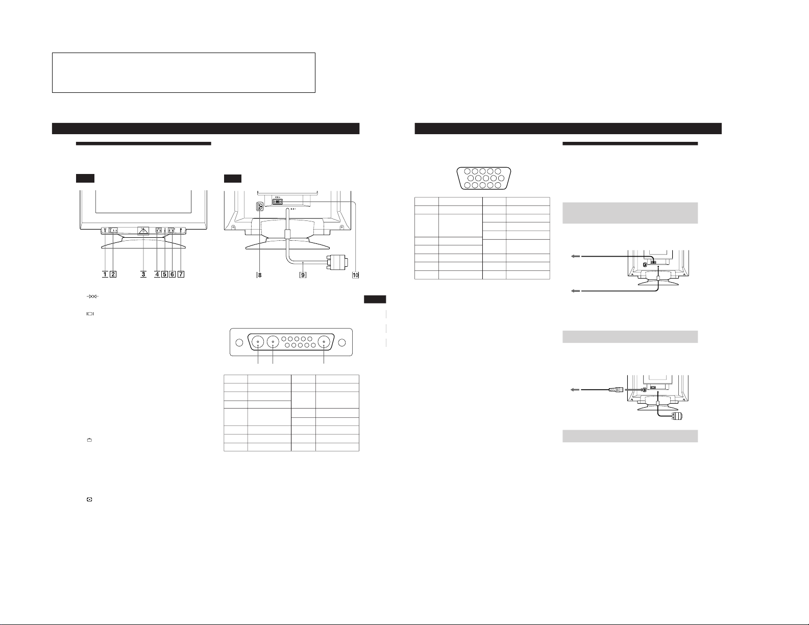
Identifying Parts and Controls
See the pages in parentheses for further details.
Front
1 (reset) button (page 16)
Resets the adjustments to the factory settings.
2 (input) button and 1 (13W3) / 2 (HD15)
indicators (pages 7 – 8)
Selects the 1 (13W3) or 2 (HD15) video input signal.
Each time you press this button, the input signal and
corresponding indicator alternate.
3 u (power) switch and indicator (pages 17,
20)
Turns the monitor on or off.
The indicator lights up in green when the monitor is
turned on, and lights up in orange when the monitor is
in power saving mode.
4 ¨ (brightness) (./>) buttons (pages 8 –
16)
Adjust the picture brightness.
Function as the (./>) buttons when adjusting other
items.
5
(menu) button (pages 7, 9 -16)
Displays the MENU OSD.
6 > (contrast) (?//) buttons (pages 8 – 16,
20)
Adjust the contrast.
Function as the (?//) buttons when adjusting other
items.
7 (auto sizing and centering) button
(page 7)
Automatically adjusts the size and centering of the
images.
Rear
8 AC IN connector
Provides AC power to the monitor.
9 Video input 1 connector (13W3 cable)
Inputs RGB video signal (0.700 Vp-p, positive).
* Pins serve a dual purpose as combined sync input and as H.sync
input if V.Sync is present on pin no. 7.
** Display Data Channel (DDC) Standard by VESA
Note
If you use a computer or video board of high output level (about 1.0
Vp-p), you may not be able to obtain the optimum display. In such
case, try decreasing the picture contrast, or use a computer or video
board with a lower output level.
(continued)
Pin No.
A1
A2
A3
1
2
3
4
Signal
C.Sync*
Bi-Directional
Data (SDA)**
V.Sync
ID (100 Ω)
ID (100 Ω)
Ground
Pin No.
5
6
7
8
9
10
Signal
Red
Green
Blue
Data Clock
(SCL)**
DDC + 5V**
––
DDC Ground**
A3
A2
A1
5 4 3 2 1
9 8 7 610
The operating instructions mentioned here are partial abstracts
6
Getting Started
!º Video input 2 connector (HD15)
Inputs RGB video signals (0.700 Vp-p, positive) and
SYNC signals.
* Display Data Channel (DDC) Standard of VESA
Setup
Before using this monitor, check that the following items are
included in your carton:
• Monitor (1)
• These operating instructions (1)
Step 1: Connect the monitor to the
computer
With the computer switched off, connect the video signal
cable to the video output of the computer.
Note
Do not short the pins of the video signal cable.
Step 2: Connect the power cord
With the monitor switched off, connect one end of the
proper power cord for your local supply to the monitor and
the other end to a power outlet.
Step 3: Turn on the monitor and computer
The installation of your monitor is complete.
Note
If “OUT OF SCAN RANGE” or “NO INPUT SIGNAL” appears on
the screen, see “Warning Messages” on page 18.
to a computer with an
HD15 video output
to a computer with a
13W3 video output
to a power outlet
Power cord
to AC IN
Pin No.
1
2
3
4
5
6
7
Pin No.
8
9
10
11
12
13
14
15
Signal
Red
Green
(Composite
Sync on Green)
Blue
––
DDC Ground*
Red Ground
Green Ground
Signal
Blue Ground
DDC + 5V*
Ground
––
Bi-Directional
Data (SDA)*
H. Sync
V. Sync
Data Clock(SCL)*
5 4 3 2
1
678910
111213
1415
from the Operating Instruction Manual. The page numbers of
the Operating Instruction Manual remain as in the manual.
SECTION 1
GENERAL
1-1
7
Getting Started
Getting Started
F
EN
ES
C
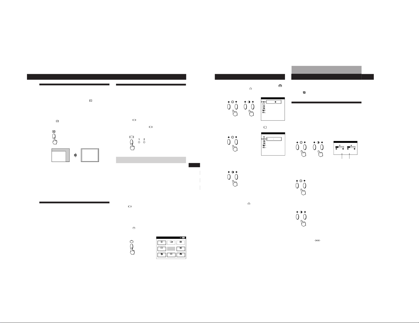
Automatically Adjusting the Size
and Centering of the Picture
By pressing the auto sizing and centering (
) button, the
size and centering of the picture are automatically adjusted
to fit the screen.
1
Turn on the monitor and computer.
2
Press the
button.
The picture is adjusted to fit the center of the screen.
Notes
• This function may not work properly if the background color is
dark or if the input picture does not fill the screen to the edges.
• The screen may go blank for a few seconds while performing the
auto-sizing function. This is not a malfunction.
• Although the signals for picture aspect ratio 5:4 (resolution: 1280
× 1024) do not fill the screen to the edges, the picture is
accurately displayed.
Selecting the On-screen Display
Language
If you need to change the OSD language, see “Using the
LANG (Language) On-screen Display” on page 16.
The default setting is English.
Selecting the Input Signal
This monitor has two signal input connectors (13W3 pigtail
cable and HD15 connector) and can be connected to two
computers. When the power of both computers is on, select
the input signal you want to view as follows.
1
Turn on the monitor and both computers.
2
Press the button to select 1 (13W3) or 2 (HD15)
input signal.
Each time you press the
button, the input signal and
corresponding indicator alternate.
Selecting the INPUT signal mode
This monitor has two modes of input signal selection,
“AUTO” and “MANUAL.”
When “AUTO” is selected
If no signal is input from the selected connector, the monitor
automatically selects the other connector’s signal. When you
restart the computer you want to view, or that computer is
in power saving mode, the monitor may automatically
select the other connector’s signal. This is because the
monitor switches from the interrupted signal to the constant
signal. If this happens, manually select the desired signal
using the
button.
When “MANUAL” is selected
Even if no signal is input from the selected connector, the
monitor does not select the other connector’s signal.
1
Press the
button.
The MENU OSD appears.
MENU
EXIT
CENTER
SIZE
GEOM
COLOR
LANG
ZOOM
SCREEN
OPTION
OK
MENU
(continued)
8
Getting Started
2
Press the ¨./> and >?// buttons to select “
OPTION,” and press the
button again.
The OPTION OSD appears.
3
Press the ¨./> buttons to select “
(INPUT).”
4
Press the >?// buttons to select “AUTO” or
“MANUAL.”
The OPTION OSD automatically disappears after about 30
seconds.
To close the OSD, press the
button again.
For more information on using the OSD, see “Introducing
the On-screen Display System” on page 9.
ON
MANUAL DEGAUSS
UNLOCK
1 MIN
OPTION
ZZ...
AUTO
ZZ...
INPUT
1 MIN
OPTION
UNLOCK
MANUAL
Horizontal
Frequency*
Vertical
Frequency*
Before adjusting
• Connect the monitor and the computer, and turn them on.
• Select “
LANG” in the MENU OSD, then select
“ENGLISH” (see page 16).
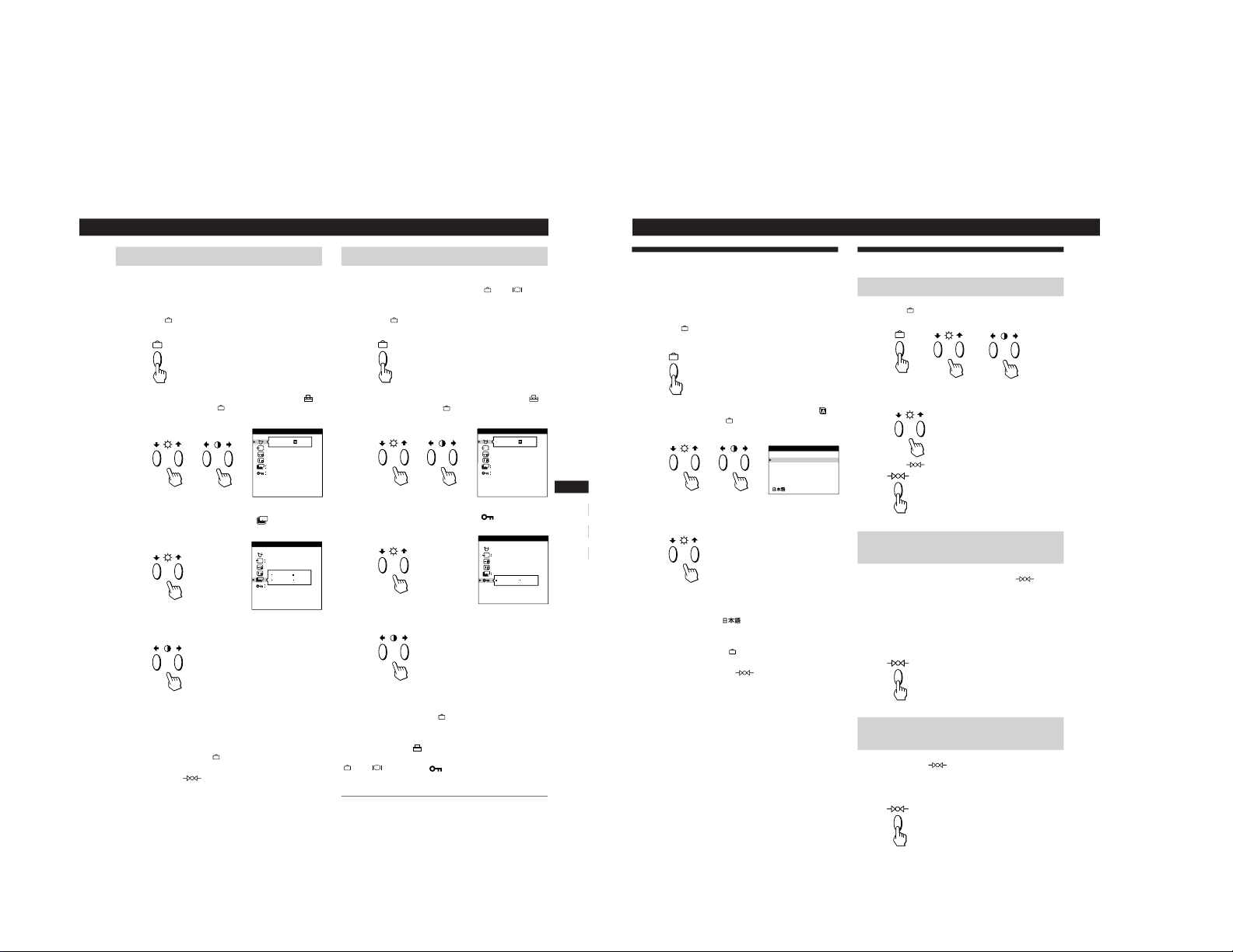
Adjusting the Picture Brightness
and Contrast
Once the setting is adjusted, it will be stored in memory for
all input signals received.
1
Press the ¨ (brightness) ./> or > (contrast) ?//
buttons.
The BRIGHTNESS/CONTRAST OSD appears.
2
For brightness adjustment
Press the ¨./> buttons.
> . . . for more brightness
. . . . for less brightness
For contrast adjustment
Press the >?// buttons.
/ . . . for more contrast
? . . . for less contrast
The OSD automatically disappears after about 3 seconds.
To reset, press the
(reset) button while the OSD is on.
The brightness and contrast are both reset to the factory
settings.
* The horizontal and vertical frequencies for the received input
signal appear in the BRIGHTNESS/CONTRAST OSD.
Customizing Your Monitor
BRIGHTNESS/CONTRAST
26 26
80.0kHz/ 75Hz
1-2
9
Getting Started
Customizing Your Monitor
F
EN
ES
C
Using the CENTER On-screen
Display
The CENTER settings allow you to adjust the centering of
the picture.
Once the setting is adjusted, it will be stored in memory for
the current input signal.
1
Press the
button.
The MENU OSD appears.
2
Press the ¨./> and >?// buttons to select “
CENTER,” and press the
button again.
The CENTER OSD appears.
3
For horizontal adjustment
Press the >?// buttons.
/ . . . to move the picture right
? . . . to move the picture left
For vertical adjustment
Press the ¨./> buttons.
> . . . to move the picture up
. . . . to move the picture down
The OSD automatically disappears after about 30 seconds.
To close the OSD, press the
button again.
To reset, press the
(reset) button while the OSD is on.
The horizontal and vertical centerings are both reset to the
factory settings.
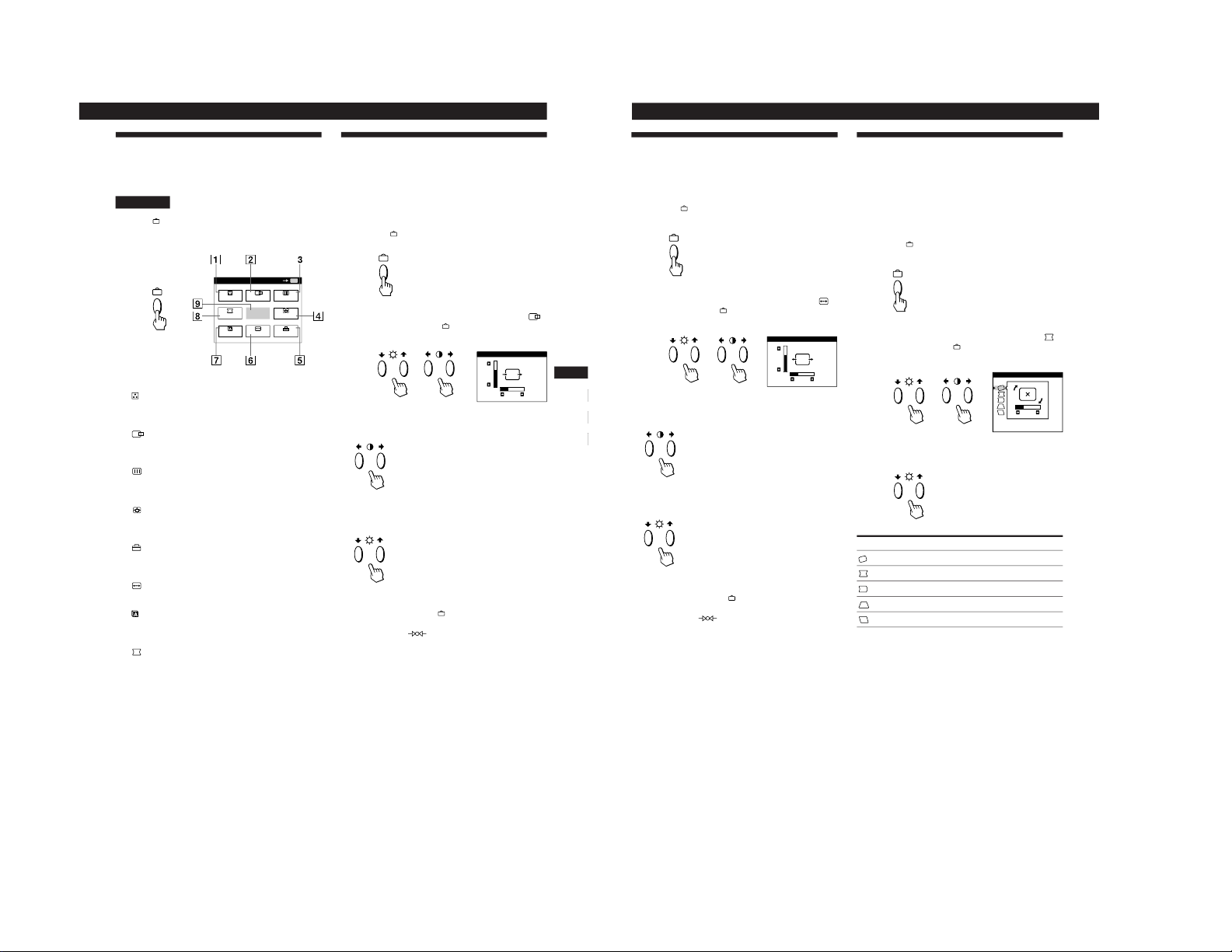
Introducing the On-screen
Display System
Most adjustments are made using the MENU OSD.
MENU OSD
Press the
button to display the MENU OSD.
This MENU OSD contains links to the other OSDs described
below.
1 COLOR
Displays the COLOR OSD for adjusting the color
temperature.
2
CENTER
Displays the CENTER OSD for adjusting the centering
of the picture.
3
SCREEN
Displays the SCREEN OSD for adjusting the vertical
and horizontal convergence, etc.
4
ZOOM
Displays the ZOOM OSD for enlarging and reducing
the picture.
5 OPTION
Displays the OPTION OSD for adjusting the OSD
position and degaussing the screen, etc.
6 SIZE
Displays the SIZE OSD for adjusting the picture size.
7 LANG
Displays the LANGUAGE OSD for selecting the
language.
8 GEOM
Displays the GEOMETRY OSD for adjusting the picture
rotation and pincushion, etc.
9 EXIT
Closes the MENU OSD.
MENU
EXIT
CENTER
SIZE
GEOM
COLOR
LANG
ZOOM
SCREEN
OPTION
OK
MENU
CENTER
26
73
10
Customizing Your Monitor
Using the SIZE On-screen Display
The SIZE settings allow you to adjust the size of the picture.
Once the setting is adjusted, it will be stored in memory for
the current input signal.
1
Press the button.
The MENU OSD appears.
2
Press the ¨./> and >?// buttons to select “
SIZE,” and press the
button again.
The SIZE OSD appears.
3
For horizontal adjustment
Press the >?// buttons.
/ . . . to increase picture size
? . . . to decrease picture size
For vertical adjustment
Press the ¨./> buttons.
> . . . to increase picture size
. . . . to decrease picture size
The OSD automatically disappears after about 30 seconds.
To close the OSD, press the
button again.
To reset, press the
(reset) button while the OSD is on.
The horizontal and vertical sizes are both reset to the factory
settings.
SIZE
26
73
Using the GEOM (Geometry) Onscreen Display
The GEOM (geometry) settings allow you to adjust the
shape and orientation of the picture.
Once the rotation is adjusted, it will be stored in memory for
all input signals received. All other adjustments will be
stored in memory for the current input signal.
1
Press the
button.
The MENU OSD appears.
2
Press the ¨./> and >?// buttons to select “
GEOM,” and press the
button again.
The GEOMETRY OSD appears.
3
Press the ¨./> buttons to select the item you want
to adjust.
Select
ROTATION
PINCUSHION
PIN BALANCE
KEYSTONE
KEY BALANCE
To
adjust the picture rotation
adjust the picture sides
adjust the picture side balance
adjust the picture width at the top
adjust the picture shape balance
ROTATION
GEOMETRY
26
1-3
11
Getting Started
Customizing Your Monitor
F
EN
ES
C
4
Press the >?// buttons to adjust the settings.
The OSD automatically disappears after about 30 seconds.
To close the OSD, press the
button again.
To reset, press the
(reset) button while the OSD is on.
The selected item is reset to the factory setting.
For
ROTATION
PINCUSHION
PIN BALANCE
KEYSTONE
KEY BALANCE
Press
/ . . . to rotate the picture clockwise
? . . . to rotate the picture counterclockwise
/ . . . to expand the picture sides
? . . . to contract the picture sides
/ . . . to move the picture sides to the right
? . . . to move the picture sides to the left
/ . . . to increase the picture width at the
top
? . . . to decrease the picture width at the
top
/ . . . to move the top of the picture to
the right
? . . . to move the top of the picture to
the left
Using the ZOOM On-screen
Display
The ZOOM settings allow you to enlarge or reduce the
picture.
Once the setting is adjusted, it will be stored in memory for
the current input signal.
1
Press the button.
The MENU OSD appears.
2
Press the ¨./> and >?// buttons to select “
ZOOM,” and press the
button again.
The ZOOM OSD appears.
3
Press the >?// buttons to adjust the picture zoom.
/ . . . to enlarge the picture
? . . . to reduce the picture
The OSD automatically disappears after about 30 seconds.
To close the OSD, press the
button again.
To reset, press the
(reset) button while the OSD is on.
Note
The picture zoom adjustment will stop as soon as either the
horizontal or vertical size reaches its maximum or minimum value.
ZOOM
73V
26H
12
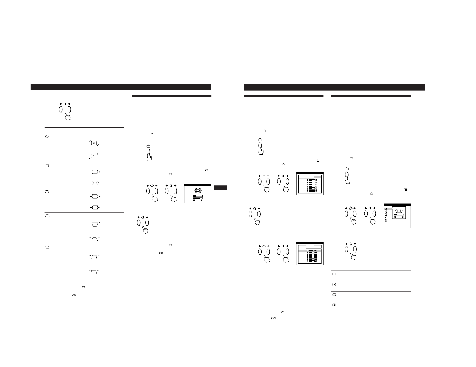
Customizing Your Monitor
Using the SCREEN On-screen
Display
You can adjust convergence settings to eliminate red or blue
shadows that may appear around objects on the screen.
Adjust the CANCEL MOIRE function to eliminate wavy or
elliptical patterns that may appear on the screen.
Adjust the LANDING function to correct color imbalances
at the four corners of the screen due to influence from the
earth’s magnetism.
Once CANCEL MOIRE is adjusted, it will be stored in
memory for the current input signal. All other adjustments
will be stored in memory for all input signals received.
1
Press the
button.
The MENU OSD appears.
2
Press the ¨./> and >?// buttons to select “
SCREEN,” and press the
button again.
The SCREEN OSD appears.
3
Press the ¨./> buttons to select the item you want
to adjust.
Using the COLOR On-screen Display
You can change the monitor’s color temperature. For
example, you can adjust or change the colors of a picture on
the screen to match the actual colors of the printed picture.
Once the setting is adjusted, it will be stored in memory for
all input signals received.
1
Press the
button.
The MENU OSD appears.
2
Press the ¨./> and >?// buttons to select “
COLOR,” and press the
button again.
The COLOR OSD appears.
3
Press the >?// buttons to select the color
temperature.
There are three color temperature
modes in the OSD.
The preset adjustments are:
5000K, 6500K, 9300K
4
Fine tuning the color temperature
Press the ¨./> buttons to select an item and adjust by
pressing the >?// buttons.
Select R (red), G (green), or B (blue) BIAS to adjust the
black level of each color’s signal.
Select R (red), G (green), or B (blue) GAIN to adjust the
white level of each color’s signal.
The “5000K,” “6500K” or “9300K” disappears and the
new color settings are memorized for each of the three
color modes.
The color temperature modes change as follows:
5000Kn 1, 6500Kn 2, 9300Kn 3
The OSD automatically disappears after about 30 seconds.
To close the OSD, press the
button again.
To reset, press the
(reset) button while the OSD is on.
The selected item is reset to the factory settings.
Select
H CONVERGENCE
V CONVERGENCE
TOP
V CONVER TOP
BOT
V CONVER BOTTOM
To
adjust the horizontal convergence
adjust the vertical convergence
adjust the screen’s upper vertical
convergence
adjust the screen’s lower vertical
convergence
SCREEN
TOP
BOT
H CONVERGENCE
26
ADJ
COLOR
R BI AS
5000K 6500K
50
G BI AS
50
B BI AS
50
R GAIN
50
G GAIN
50
B GAIN
50
9300K
COLOR
6500K 9300K
G BI AS
50
B BI AS
50
R GAIN
50
G GAIN
50
B GAIN
50
R BI AS
76
1
1-4

13
Getting Started
F
EN
ES
C
Customizing Your Monitor
* Moire is a type of natural interference which produces soft or
wavy lines on your screen. It may appear due to interference
between the regulated pattern of the picture from the input
signal and the phosphor pitch pattern of the CRT.
Example of moire:
4
Press the >?// buttons to adjust the settings.
Note
The picture may become fuzzy when CANCEL MOIRE is set to
“ON.”
The OSD automatically disappears after about 30 seconds.
To close the OSD, press the
button again.
To reset, press the
(reset) button while the OSD is on.
The selected item is reset to the factory setting.
ON
OFF
ON
OFF
50
For
BOT
V CONVER BOTTOM
LANDING
ADJ
LANDING ADJUST
CANCEL MOIRE
ADJ
MOIRE ADJUST
Press
/ . . . to shift red shadows up and blue
shadows down
? . . . to shift red shadows down and
blue shadows up
/ or ? . . . to select the corner of the
screen you want to adjust
: top left
: top right
: bottom left : bottom right
/ or ? . . . to reduce any irregularities in
the color to a minimum
/ . . . to turn CANCEL MOIRE “ON”
? . . . to turn CANCEL MOIRE “OFF”
/ or ? . . . to adjust the screen until the
moire is at a minimum
Select
LANDING
ADJ
LANDING ADJUST
CANCEL MOIRE *
ADJ
MOIRE ADJUST
To
select one of the four corners that
needs color correction due to
influence from the earth’s magnetism
correct the color at one of the four
corners of the screen
turn the moire cancellation function
“ON” or “OFF.” CANCEL MOIRE
must be “ON” for “
ADJ (MOIRE
ADJUST)” to appear on the screen.
adjust the degree of moire
cancellation
For
H CONVERGENCE
V CONVERGENCE
TOP
V CONVER TOP
Press
/ . . . to shift red shadows to the right
and blue shadows to the left
? . . . to shift red shadows to the left
and blue shadows to the right
/ . . . to shift red shadows up and blue
shadows down
? . . . to shift red shadows down and
blue shadows up
/ . . . to shift red shadows up and blue
shadows down
? . . . to shift red shadows down and
blue shadows up
50
14
Customizing Your Monitor
Using the OPTION On-screen
Display
The OPTION OSD allows you to manually degauss the
screen and adjust settings such as the OSD position and
power saving delay time. It also allows you to lock the
controls.
Degaussing the screen
The monitor screen is automatically degaussed
(demagnetized) when the power is turned on.
You can also manually degauss the monitor.
1
Press the
button.
The MENU OSD appears.
2
Press the ¨./> and >?// buttons to select “
OPTION,” and press the
button again.
The OPTION OSD appears.
3
Press the ¨./> buttons to select “
(MANUAL
DEGAUSS).”
4
Press the > / button.
The screen is degaussed for about 3 seconds.
If you need to degauss the screen a second time, wait for at
least 20 minutes before repeating the steps above.
The OPTION OSD automatically disappears after about 30
seconds.
To close the OSD, press the
button again.
Changing the on-screen display position
You can change the OSD position (for example, when you
want to adjust the picture behind the OSD).
1
Press the
button.
The MENU OSD appears.
2
Press the ¨./> and >?// buttons to select “
OPTION,” and press the
button again.
The OPTION OSD appears.
3
Press the ¨./> buttons to select “
(OSD H
POSITION)” or “
(OSD V POSITION).”
Select “
(OSD H POSITION)” to adjust the horizontal
position.
Select “
(OSD V POSITION)” to adjust the vertical
position.
4
Press the >?// buttons to move the OSD to the
desired position.
The OPTION OSD automatically disappears after about 30
seconds.
To close the OSD, press the
button again.
To reset, press the
(reset) button while the OSD is on.
ON
MANUAL DEGAUSS
UNLOCK
1 MIN
OPTION
ZZ...
ON
MANUAL DEGAUSS
UNLOCK
1 MIN
OPTION
ZZ...
ZZ...
OSD H POSITION
UNLOCK
1 MIN
OPTION
ZZ...
OSD V POSITION
UNLOCK
OPTION
AUTO
1-5
15
Getting Started
F
EN
ES
C
Customizing Your Monitor
Locking the controls
The control lock function disables all of the buttons on the
front panel except the u (power) switch,
and
buttons.
1
Press the
button.
The MENU OSD appears.
2
Press the ¨./> and >?// buttons to select “
OPTION,” and press the
button again.
The OPTION OSD appears.
3
Press the ¨./> buttons to select “
(CONTROL
LOCK).”
4
Press the >?// buttons to select “LOCK.”
The OPTION OSD automatically disappears after about 30
seconds.
To close the OSD, press the
button again.
Once you select “LOCK,” you cannot select any items
except “EXIT” and ”
OPTION” in the MENU OSD.
If you press any button other than the u (power) switch,
and
buttons, the mark appears on the screen.
To cancel the control lock
Repeat steps 1 through 3 above and press the >?//
buttons to select “UNLOCK.”
Setting the power saving delay time
You can set the delay time before the monitor enters the
power saving mode. See page 17 for more information on
this monitor’s power saving capabilities.
1
Press the
button.
The MENU OSD appears.
2
Press the ¨./> and >?// buttons to select “
OPTION,” and press the
button again.
The OPTION OSD appears.
3
Press the ¨./> buttons to select “
ZZ...
(PWR SAVE
DELAY).”
4
Press the >?// buttons to select the desired time.
When PWR SAVE DELAY is set to “OFF,” the monitor
does not go into power saving mode.
The OPTION OSD automatically disappears after about 30
seconds.
To close the OSD, press the
button again.
To reset, press the
(reset) button while the OSD is on.
ON
MANUAL DEGAUSS
UNLOCK
1 MIN
OPTION
ZZ...
ON
MANUAL DEGAUSS
UNLOCK
1 MIN
OPTION
ZZ...
ZZ...
PWR SAVE DELAY
OPTION
5 SEC
60 MIN
1 MIN
OFF
AUTO
ZZ...
CONTROL LOCK
OPTION
UNLOCK LOCK
AUTO
16
Customizing Your Monitor
Using the LANG (Language) Onscreen Display
English, French, German, Spanish, Italian and Japanese
versions of the OSDs are available.
1
Press the button.
The MENU OSD appears.
2
Press the ¨./> and >?// buttons to select “
LANG,” and press the
button again.
The LANGUAGE OSD appears.
3
Press the ¨./> buttons to select the desired
language.
ENGLISH: English, FRANÇAIS: French,
DEUTSCH: German, ESPAÑOL: Spanish,
ITALIANO: Italian, or
: Japanese.
The OSD automatically disappears after about 30 seconds.
To close the OSD, press the
button again.
To reset to English, press the
(reset) button while the
OSD is on.
Resetting the Adjustments
Resetting an adjustment item
1
Press the , ¨./> and >?//buttons to select
the OSD containing the item you want to reset.
2
Press the ¨./> buttons to select the item you want
to reset.
3
Press the (reset) button.
Resetting all of the adjustment data for
the current input signal
When there is no OSD displayed, press the
(reset)
button.
All of the adjustments data for the current input signal is
reset to the factory settings.
Note that adjustment data not affected by changes in input
signal (OSD language, OSD position, input signal selection,
power saving delay time and the control lock function) is
not reset to the factory settings.
Resetting all of the adjustment data for all
input signals
Press and hold the (reset) button for more than
two seconds.
All of the adjustment data, including the brightness and
contrast, is reset to the factory settings.
ENGLISH
FRANÇAIS
DEUTSCH
ESPAÑOL
ITALIA NO
LANGUAGE
1-6
17
Getting Started
F
EN
ES
C
Technical Features
Power Saving Function
This monitor meets the power-saving guidelines set by
VESA and Energy Star, as well as the more stringent
NUTEK .
In particular, the monitor is capable of entering a low power
state when it is inactive and used with an Energy Star
capable framebuffer and appropriate Sun system software.
u indicator
Green
Green and orange
alternate
Green and orange
alternate
Orange
Off
Power consumption
mode
Normal operation
Standby (1st mode)
Suspend (2nd mode)
Active-off (3rd mode)
Power-off
You can set the delay time before the monitor enters the
power saving mode using the OSD. Set the time according
to “Setting the power saving delay time” on page 15.
Note
If no video signal is input to the monitor, the “NO INPUT
SIGNAL” message (page 18) appears. After the delay time has
passed, the power saving function automatically puts the monitor
into the active-off mode and the u indicator lights up orange. Once
the horizontal and vertical sync signals are detected, the monitor
automatically resumes its normal operation mode.
Damper Wires
When viewing a white background, very thin horizontal
lines may be visible on the screen as shown below. These
lines are the shadows of the damper wires and are
characteristic of CRTs that use aperture grilles. The wires
are attached to the aperture grille on the inside of the
Trinitron tube and prevent the vibration of the aperture
grille.
Damper wires
Plug & Play
This monitor complies with the DDC1, DDC2B, DDC2AB
and DDC2B+ Display Data Channel (DDC) standards of
VESA.
When a DDC1 host system is connected, the monitor
synchronizes with the V. CLK in accordance with the VESA
standards and outputs the EDID (Extended Display
Identification Data) to the data line.
When a DDC2B, DDC2AB or DDC2B+ host system is
connected, the monitor automatically switches to the
appropriate standard.
DDC is a trademark of the Video Electronics Standard
Association.
Technical Features
1
2
3
4
5
Power
consumption
≤ 160 W
≤ 100 W
≤ 15 W
≤ 5 W
< 1.0 W
Recovery time
—
Approx. 3 sec.
Approx. 3 sec.
Approx. 10 sec.
—
Screen
active
blank
blank
blank
—
Horizontal
sync signal
present
absent
present
absent
—
Vertical
sync signal
present
present
absent
absent
—
Preset Modes
Mode
1
2
Resolution
(dots × lines)
1280 × 1024
1152 × 900
Horizontal
Frequency
81.1 kHz
71.8 kHz
Vertical
Frequency
76Hz
76Hz
18
Additional Information
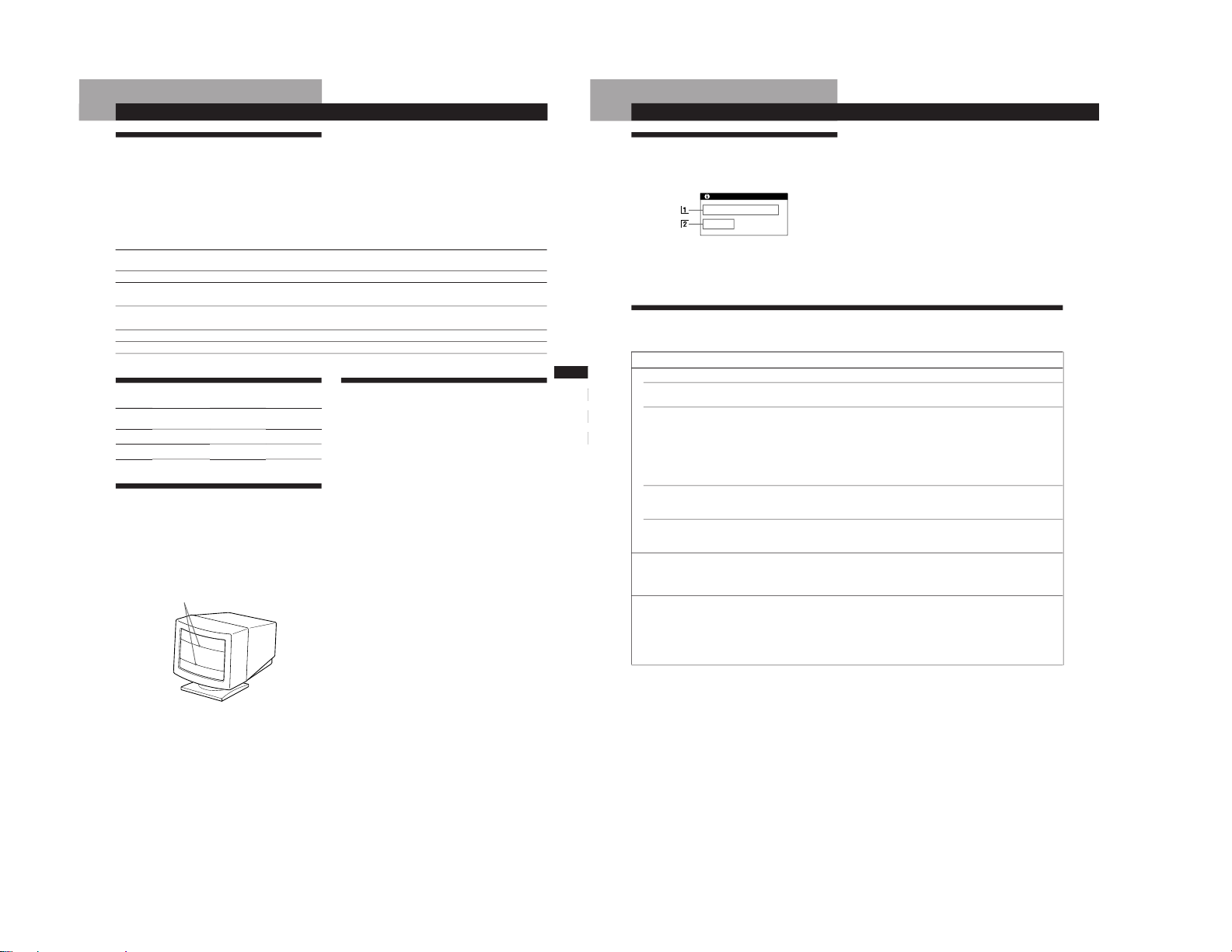
Warning Messages
If there is something wrong with the input signal, one of the
following messages appears.
Additional Information
1 The input signal condition
“OUT OF SCAN RANGE” indicates that the input signal
is not supported by the monitor’s specifications.
“NO INPUT SIGNAL” indicates that no signal is input, or
the input signal from the selected input connector is not
received.
2 The selected input connector
Indicates which input connector is receiving the wrong
signal. If there is something wrong with the signal from
both input connectors, “1” (13W3) and “2” (HD15) are
displayed alternately.
To solve these problems, see “Troubleshooting” below.
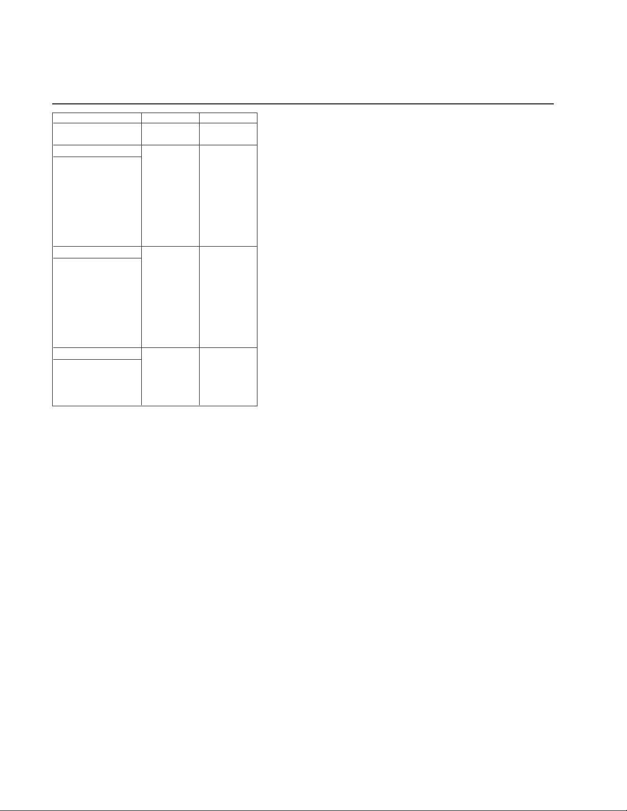
Tr oubleshooting
This section may help you isolate the cause of a problem and as a result, eliminate the need to contact technical support.
Symptom Check these items
No picture
If the u indicator is not lit
If the “NO INPUT SIGNAL”
message appears on the screen,
or if the u indicator is either
orange or alternating between
green and orange
If the “OUT OF SCAN RANGE”
message appears on the screen
If no message is displayed and
the u indicator is green or
flashing orange
Picture is scrambled
Color is not uniform
• Check that the power cord is properly connected.
• Check that the u (power) switch is in the “on” position.
• The screen is blank when the monitor is in power saving mode. Try pressing any key on the
computer keyboard.
• Check that your computer power switch is in the “on” position.
• Check that the input select setting is correct.
• Check that the video signal cable is properly connected and all plugs are firmly seated in
their sockets.
• Ensure that no pins are bent or pushed in the 13W3 video input cable.
• Check that the video board is completely seated in the proper bus slot.
• Check that the video frequency range is within that specified for the monitor.
(Horizontal: 30 – 96 kHz, Vertical: 48 – 160 Hz)
Refer to your computer‘s instruction manual to adjust the video frequency range.
• See “Self-diagnosis Function” (page 20).
• Check your graphics board manual for the proper monitor setting.
• Check this manual and confirm that the graphics mode and the frequency you are trying to
operate at is supported. Even if the frequency is within the proper range, some video
boards may have a sync pulse that is too narrow for the monitor to sync correctly.
• Degauss the monitor (page 14).
If you place equipment which generates a magnetic field, such as a loudspeaker, near the
monitor, or you change the direction of the monitor, color may lose uniformity.
The degauss function demagnetizes the metal frame of the CRT to obtain a neutral field for
uniform color reproduction. If a second degauss cycle is needed, allow a minimum interval
of 20 minutes for the best result.
• Adjust the landing (pages 12 – 13).
INFORMATION
OUT OF SCAN RANGE
INPUT : 1
1-7
19
Getting Started
Additional Information
F
EN
D
ES
I
Symptom Check these items
You cannot adjust the monitor
with the buttons on the front
panel
White does not look white
Screen image is not centered or
sized properly
Edges of the image are curved
White lines show red or blue
shadows at edges
Picture is fuzzy
Picture bounces or has wavy
oscillations
Picture is flickering
Picture appears to be ghosting
Wavy or elliptical (moire)
pattern is visible
Two fine horizontal lines
(wires) are visible
Hum is heard right after the
power is turned on
• If the control lock function is set to on, set it to off using the OPTION OSD (page 15).
• Adjust the color temperature (page 12).
• Press the
button (page 7).
• Adjust the size or centering (pages 9 – 10).
• Adjust the geometry (pages 10 – 11).
• Adjust the convergence (pages 12 – 13).
• Adjust the contrast and brightness (page 8).
• Degauss the monitor (page 14).
If you place equipment which generates a magnetic field, such as a loudspeaker, near the
monitor, or you change the direction of the monitor, color may lose uniformity.
The degauss function demagnetizes the metal frame of the CRT to obtain a neutral field for
uniform color reproduction. If a second degauss cycle is needed, allow a minimum interval
of 20 minutes for the best result.
• If red or blue shadows appear along the edges of images, adjust the convergence
(pages 12 – 13).
• If the moire is cancelled, the picture may become fuzzy. Decrease the moire cancellation
effect (pages 12 – 13).
• Isolate and eliminate any potential sources of electric or magnetic fields. Common causes
for this symptom are electric fans, fluorescent lighting or laser printers.
• If you have another monitor close to this monitor, increase the distance between them to
reduce the interference.
• Try plugging the monitor into a different AC outlet, preferably on a different circuit.
• Try the monitor on a different computer in a different room.
• Set the refresh rate on the computer to obtain the best possible picture by referring to the
computer’s manual.
• Eliminate the use of video cable extensions and/or video switch boxes if this symptom
occurs. Excessive cable length or a weak connection can produce this symptom.
• Cancel the moire (pages 12 – 13).
The moire may be modified depending on the connected computer.
• Due to the relationship between resolution, monitor dot pitch and the pitch of some image
patterns, certain screen backgrounds sometimes show moire. Change your desktop pattern.
• These wires stabilize the vertically striped aperture grille (page 17). This aperture grille
allows more light to pass through to the screen giving the Trinitron CRT more color and
brightness.
• When the power is turned on, the auto-degauss cycle is activated. While the auto-degauss
cycle is activated (3 seconds), a hum may be heard. The same hum is heard when the
monitor is manually degaussed. This is not a malfunction.
20
Additional Information
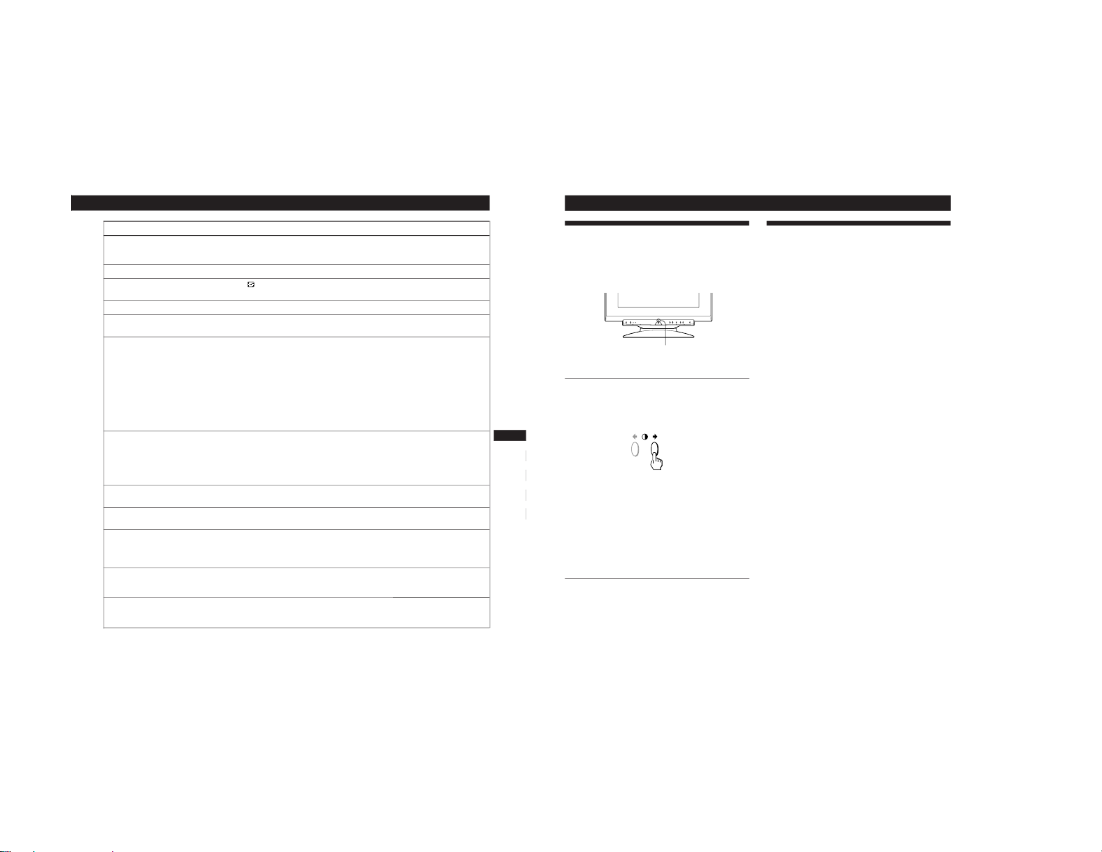
Self-diagnosis Function
This monitor is equipped with a self-diagnosis function. If
there is a problem with your monitor or computer(s), the
screen will go blank and the u indicator will either light up
green or flash orange.
If the
uu
uu
u indicator is green
1
Disconnect video input 1 and 2, or turn off the
connected computer(s).
2
Press and hold the >/ button for 2 seconds.
If all four color bars appear (white, red, green, blue), the
monitor is working properly. Reconnect the video input
cables and check the condition of your computer(s).
If the color bars do not appear, there is a potential
monitor failure. Inform your authorized Sun dealer of
the monitor’s condition.
If the
uu
uu
u indicator is flashing orange
Press the
uu
uu
u button to turn the monitor off and on.
If the u indicator lights up green, the monitor is
working properly.
If the u indicator is still flashing, there is a potential
monitor failure. Count the number of seconds between
orange flashes of the u indicator and inform your
authorized Sun dealer of the monitor’s condition. Be
sure to note the model name and serial number of your
monitor. Also note the make and model of your
computer and video board.
u indicator
Specifications
Picture tube 0.25 – 0.27 mm aperture grille pitch
21 inches measured diagonally
90-degree deflection
Viewable image size Approx. 403.8 × 302.2 mm (w/h)
(16 × 12
inches)
19.8” viewing image measured
diagonally
Resolution Horizontal: Max. 1600 dots
Vertical: Max. 1200 lines
Standard image area Approx. 388 × 291 mm (w/h)
(15
3
/8 × 11 1/2 inches)
or
Approx. 364 × 291 mm (w/h)
(14
3
/8 × 11 1/2 inches)
Deflection frequency Horizontal: 30 to 96 kHz
Vertical: 48 to 160 Hz
AC input voltage/current
100 to 240 V, 50 – 60 Hz, 2.0 – 1.0 A
Power consumption Max. 160 W
Dimensions 500.3 × 502.5 × 476.5 mm (w/h/d)
(19
3
/4 × 19 7/
8
× 18 7/8 inches)
Mass Approx. 31 kg (68 lb 5 oz)
Design and specifications are subject to change without
notice.
1-8
GDM-5010PT
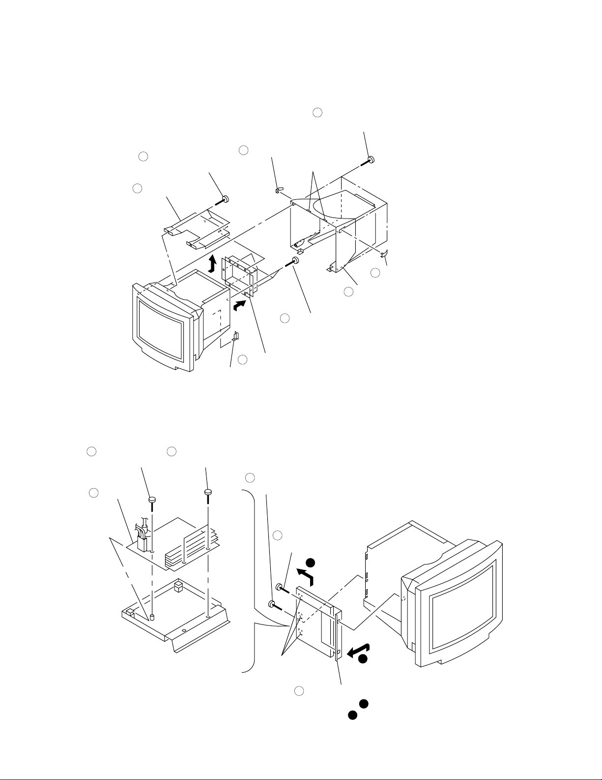
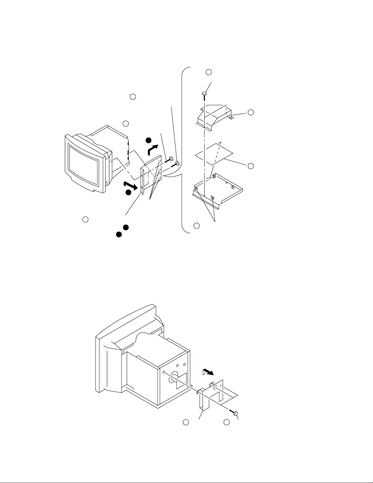
2-1. REAR BUCKET ASSY REMOVAL
5
Four screws
(+ BVTT 4 x 8)
6
Top cover
SECTION 2
DISASSEMBLY
3
Four screws
1
Screw cover
Two claws
7
Four screws
(+ BVTT 4 x 8)
(+ BVTP 4 x 16)
2
Screw cover
4
Rear bucket assy
2-2. D BOARD REMOVAL
4 5
Screw
(+ P 3.5 x 20)
6
D board
Two screws
(+ BVTP 3 x 10)
8
Pig tail cover
1
Video shield
Screw
(+ BVTT 4 x 8)
2
Two screws
(+ BVTT 4 x 8)
B
Three hooks
3
Open the D block in the direction
of the arrow . and remove of
the arrow .
2-1
A
A
B
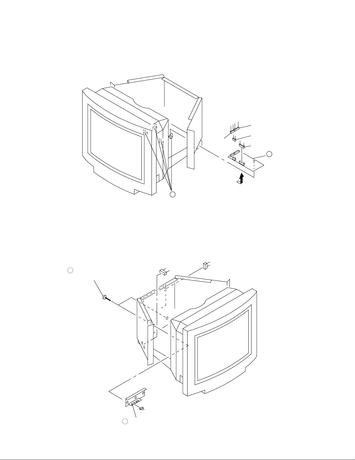
2-3. G BOARD REMOVAL
2
A
1
Screw
(+ BVTT 4 x 8)
Two screws
(+ BVTT 4 x 8)
B
4
Two screws
(+BVTP 3 x 10)
5
G shield
7
G board
GDM-5010PT
3
Open the G block in the direction
of the arrow . and remove of
the arrow .
A
B
2-4. A BOARD REMOVAL
Three hooks
6
Two printed circuit board holders
A borad Three screws
12
(+BVTT 4 x 8)
2-2
GDM-5010PT
2-5. L BOARD REMOVAL
CN5002
CN5001
CN5004
CN5003
2
L board
1
2-6. I/O TERMINAL BOARD ASSY REMOVAL
CN511
1
Two screws
(+ BVTT 3 x 8)
Four printed circuit board holders
CN401
CN3908
2
I/O terminal board assy
2-3
 Loading...