

Page 1

Trinitron" Color
Graphic Display
3-861-575-13(1)
Operating instructions
Mode d'ennploi
Manual de instrucciones
_________________
___________
_
GDM-400PS
GDM-500P5
O 1997 by Sony Corporation
Page 2

Owner's Record
The model and serial ntunbers are located at the tear of the unit.
Record the serial number in the space provided below. Refer to
these numbers whenever you call upon your dealer regarding this
product.
Model No.
Serial No.
WARNSNG
To prevent fire or shock hazard, do not expose
the unit to rain or moisture.
Dangerously high voitages are present inside
the unit. Do not open the cabinet. Refer servicing
to qualified personnel oniy.
FCC Notice
This equipment has been tested arid found to coinply with the
limits for a Class B digital device, pursuant to Pari 15 of the FCC
Rules. These liiiuts are designed to provide reasonable protection
against harmful interf^ence in a residential installation. This
equipment generates, uses, and can radiate radio frequency energy
and, if not installed and used in aiccordapce with the instructions,
may cause harmful mterferertce to radio coiiuuunicatioiis.
However, there is no guarantee that interference will not occur in a
particular installation. If this equipment does cause harmful
interference to radio or television reception, which can be
determined by turning the equipment off and on, the user is
encouraged to try to correct the interference by one or more of the
following measures:
- Reorient or relocate the receiving antenna.
- Increase the separation between the equipment and receiver.
- Ccvmect the equipment into an outlet on a circuit different from that
to which the receiver is cotuiected.
- ConstJt the dealer or an exf>erieru:ed ladio/TV technician for help.
You are cautioned foat any conges or mcxlifications not expressly
approved in this manual could void your authority to operate this
equipment.
Hinweise
■ Aus ergonomischen Gründen wird empfohlen, die
Grundmrbe Blau nicht auf dunidem Untergrund zu
verwenden (schlechte Erkennbarkeit, Augenbelastung bei zu
geringem Zeichenkontrast).
■ Aus ergonomischen Gründen (flimmern) sollten nur
Darstellungen bei Vertikalfrequenzen ab 70 Hz (ohne
Zeilensprung) verwendet werden.
• Die Konveigenz des Bildes kaiut sich auf Grund des
Magnetfeldes am Ort der Aufstellung aus der korrekten
Grundeinstellung verändern. Zur Korrektur empfiehlt es sich
deshalb, die Regler an der Frontseite für Konvergeriz so
einzustellen, daS die getrennt sichtbaren Farblinien für Rot,
Grün und Blau bei z-B. der Dantellung eines Buchstabens zur
Deckung (Konvergenz) gelangen.
Siche hierzu auch die Erklärungcnizu Konvergenz.
NOTICE
This notice is applicable for USA/Canada only.
If shipped to USA/Canada, install qrily a UL LISTED/CSA
LABELLED power supply cord meeting the following
specifications:
SPECIFICATIONS
Plug Type Nema-Plug5-15p
Cord Type SVT or SJT, minimum 3 X 18 AWG
Length Maximum 1.S feet
Rating Minimum 7 A, 125 V
NOTICE
Cette notice s'applique aux Etats-Unis et au Canada
uniquement.
Si cet appareil est exporté aux Etats-Unis ou au Caruda,
utiliser le cordon d'alimentation portant la mention UL
LlSrED/CSA LABELLED et remplissant les conditions
suivantes:
SPECmCATIONS
Type de fiche
Cordon
Longueur
Tension
Fiche Nema 5-15 broches
Type SVT ou SjT, minimum 3x18 AWG
Maximum 15 pieds
Minimum 7 A, 125 V
[Vn"
INFORMATION
This product complies with Swedish National Council for
Metrology (MPR) standards issued in December 1990 (MFRII) for
very low frequetuy (VLP) and extremely low frequency (ELF).
INFORMATION
Ce produit est conforme aux normes du Swedish National Council
for Metrology de décembre 1990 (MPRII) en ce qui concerne les
fréquences très basses (VLF) et extrêmement basses (ELF).
Hinweis
Dieses Gerät erfüllt bezüglich tieffrequenter (very low frequency)
.und tieistfrequenter (extremely low frequency) Strahlung die
Vorschriften des „Swedish National Council for Metrology (MPR)"
vom Dezember 1990 (MPR II).
INFORMACIÖN
Este producto cumple las normas del Consejo Nadonal Sueco para
Metrologla (MPR) emitidas en diciembré de 1990 (MFR II) para
frecuencias muy bsjas (VLF) y frecuendas extremadamentc bajas
(ELF).
Dieses Garät entspricht den folgenden europäischen EMVVoischriften für Betrieb in Wohngebieten, gewerblicher Gebieten
Und 1.eichtindustriegebieten.
EN55022/I987 Klasse B
EN50082-1/1992
EN60Î555-2/1987
As an ENERGY STAR Partner, Sony
Corporation has determined that this
product meets the ENERGY STAR
guide! irres for energy efficiency.
This monitor complies with the
TCO 1992 guidelines for power
saving when used with a
computer equipped with .VESA
Display Power Management
Signaling (DPMS).
(GDM-400PS only)
This monitor complies with the
TCO'95 guidelines.
(GDM-500PS only)
(VCCI )®SJ|i(CSTK Í75XB ««ßiisSEr?-.
(GDM-500PS only)
Page 3

Table of contents
Getting Started
Precautions.......................................................................................................................4
Identifying Parts and Controls.........................................................................................5
Setup............................................................................................................................... 6
Automatically Adjusting the Size and Centering of the Picture..................................... 7
Selecting the On-screen Display Language
Selecting the Input Signal................................................................................................8
Customizing Your Monitor
Adjusting the Picture Brightness and Contrast................................................................9
Introducing the On-screen Display System ...................................................................
Using the CENTER On-screen Display
Using the SIZE On-screen Display
Using the GEOM (Geometry) On-screen Display.........................................................11
Using the ZOOM On-screen Display.......................................................................... 12
Using the COLOR On-screen Display
Using the SCREEN On-screen Display..............................................................
Using the OPTION On-screen Display
Using the LANG (Language) On-screen Display
Resetting the Adjustments..............................................................................................17
...........................
....................................
.......................................................................
............................................................................
..........................................................................
....................................................... ..................
............
.............................................17
...........
7
9
10
10
12
13
15
Technical Features
Preset and User Modes
................................................................................................
, Power Saving Function................................................................................................ 19
Damper Wires.............................................................................................................. 19
Plug & Play................................................................................................................. 19
Additional Information
Warning Messages.........................................................................................................20
Troubleshooting
Self-diagnosis Function
Specifications.......................................................................;
Macintosh is a trademark licensed to Apple Computer, Inc., registered .
in the U.S. A. and other countries.
Windows* and MS-DOS are registered trademarks of Microsoft
Corporation in the United States and other countries.
IBM PC/AT arwLVGA are registered trademarks of IBM Corporation of
the U.S.A.
VESA is s trademark of Video Electronics Standard Associatioit.
AU other product names mentioned herein may be the trademarks or
registered trademarks of their respective companies.
Furthermore, •'(gp mentiDned in each case in this
.......
............................................................................................... 20
...............................................................................................
.....
................................... 22
manual.
18
22
Page 4
Getting started
Precautions
« ?«x; CT:ri-
Prevent internal heat build-up by allowing adequate air
circulation. Do not place the monitor on surfaces (rugs,
blankets, etc.) or riear materials (curtains, draperies) that
may block the ventilation holes.
Do not install the monitor near heat sources such as
radiators or air ducts, or in a place subject to direct
sunlight, excessive dust, mechanical vibration or shock.
Do not place the monitor near equipment whid\ generates
magnetism, such as a transformer or high voltage power
lines.
Clean the cabinet, panel and controls with a soft cloth
lightly moistened with a mild detergent solution. Do not
use any type of abrasive pad, scouring powder or solvent,
such as alcohol or benzine.
Do not rub, touch, or tap the surface of the screen with
sharp or abrasive items such as a ballpoint pen or
screwdriver. This type of contact may result in a scratched
picture tube.
Clean the screen with a soft cloth. If you use a glass
cleaning liquid, do not use any type of cleaner containing
an anti-static solution or similar additive as this may
scratch the screen's coating.
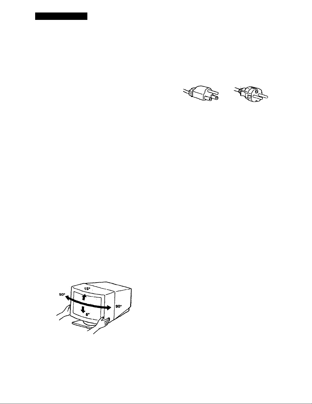
Use an appropriate power cord for your local power
supply.
For the customers in the U.S.A.
If you do not use the appropriate cord, this monitor will
not conform to mandatory FCC standards.
Examples of plug types
for foo to 120 V AC
for 200 to 240 V AC
Before discoimecting the power cord, wait at least 30
seconds after turning off the power to allow the static
electricity on the CRT display surface to discharge.
After the power has been turned on, thé CRT is
demagnetized (degaussed) for about 3 seconds. This
generates a strong magnetic field around the metal frame,
which may affect the data stored on magnetic tapes and
disks near the bezel. Place magnetic recording equipment,
tapes and disks away from this monitor.
The outlet should be installed near the equipment
and be easily accessible.
When you transport this monitor for repair or shipment, use
the original carton and packing materials.
With the tilt-swivel, this monitor can be adjusted to the
desired angle within 180° horizontally and 20° vertically.
To turn the monitor vertically and horizontally, hold it at
the bottom with both hands as illustrated below.
Page 5
Identifying Parts and Controls
See the pages in parentheses for further details.
GDM-500PS is used for illustration purposes throughout
this manual.
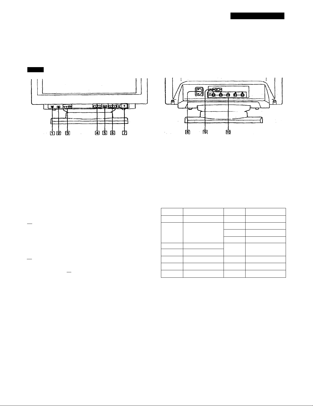
Front
Getting Started
[T] RESET (reset) button (page 17)
Resets the adjustmente to the factory settings.
d] ASC (auto sizing and centering) button
(page 7)
Automatically adjusts the size and centering of the
images.
[3] INPUT (input) button and H015/BNC
indicators (page 8)
Selects the HD15 or 5BNC video input signal. Each time
you prf^s this button^ the input signal and
corresponding indicator alternate.
ril <it- (brightness) (4'f't) buttons (pages 8 -
17)
Adjust the picture brightness.
Function as the (4/'^) buttoi^s when adjusting other
items.
[si MENU (menu) button (pages 8 -17)
Displays the MENU OSD.
(U Q (contrast) (*'■/■» ) buttons (pages 8-17,
22)
Adjust tlw contrast.
Function as the (♦“/"^►) buttons when adjusting other
items.
[7] Ci) (power) switch and indicator (pages 19,
22)
Turns the monitor on or off.
The inditator lights up in green when the monitor is
turned on, and lights up in orange when the monitor is
m power caving mode.
AC IN connector
Provides AC power to the monitor.
Video input 1 connector (HD 15)
Inputs RGB video signals (0.700 Vp-p, positive) and
SYNC signals.
©®<3)(D®
Pin No. Signal
1 Red
2
3 Blue
4
5
6
7
DUplay Data Channel (DDC) Standard of VESA
Green
(Composite
Sync on Green)
ID (Ground)
DDC Ground*
Red Ground 14 V. Sync
Green Ground
Pin No.
8
9
10 Ground
11
12
13 H. Sync
15
Signal
Blue Ground
DDC + 5V*
ID (Ground)
Bi-Directional
Data (SDA)*
DataClock(SGL)*
^ Video input 2 connector (5 BNC)
Inputs RGB video signaJs (0.700 Vp-p, positive) and
SYNC signalsT
Page 6

Getting Started
Setup
Before using this monitor, check that the following items are
included in your carton:
» Monitor (1)
• Power cord (1)
• HD15 video signal cable (1)
• Macintosh adapter (1)
• Windows* 95 Monitor Information Disk/File (1)
• TCO'95 Eco-document (1) (GDM-SOOPS otdy)
• Warranty card (1)
• These operating instructioiu (1)
This monitor works with any IBM or compatible system
equipped with VGA or greater graphics capability.
Although this monitor works with other platforms running
at horizontal frequencies between 30 and 94 kHz (GDM400PS), 30 and 107 kHz (GDM-500PS), including Macintosh
and Power Macintosh systems, a cable adapter is required.
Please consult your dealer for advice on which adapter is
suitable for. your needs.
If your PC system is not compatible with ODC2AB
and DDC2B-I-
This monitor uses the No. 9 pin in the video signal connector for
PDC2AB and DDCZB^ compatibility.
Some PC .systems which are not compatible with either DDC2AB or
DDC2B*- may not accept the No. 9 pin. If you are not sure whether
your PC system accepts the No. 9 pin or not, use the HD15 (F«anale)
- HOIS (Male without the No. 9 pin) adapter (not supplied). Make
sure tiie male side (without the No. 9 pin) is connected to the
computer.
Connecting to a Macintosh or compatible computer
With the computer switched off, connect the video signal
cable to the monitor using the supplied HD15 video signal
cable.
• If you are using an IBM PC/AT or compatible computer,
refer to the section below.
• If you are using a Macintosh or compatible computer,
refer to die following section, "Connecting to a Macintosh
or compatible computer."
• If you want to use the 5 BNC connectors, refer to the
section, "Connecting to the 5 BNC connectors."
Connecting to an IbM POAT or compatible computer
HD15 - HDIS^adapter
(not supplied)*
■* The HOIS - HDIS adapter may be needed for some models.
(supplied)
About the supplied Macintosh adapter
TTie supplied Macintosh adapter is compatible with Macintosh I.C,
Performa, Quadra and Power Macintosh series computers.
Macintosh n series and some older versions of Power Book models
may need an adapter with micro switches (not supplied).
Connecting to the 5 BNC connectors
To connect the 5 BNC connectors, use the SMF-400 video
signal cable (sold separately). Connect the cables from left to
light in the following order: Red-Green-Blue-HD-VD.
Notes
• Do not short the pins of tire video signal cable.
• The DDC standard does not apply fo the 5 BNC connectors. If
you use the DDC standard, connect the HD15 connector to the
computer with the supplied video signal cable.
Page 7
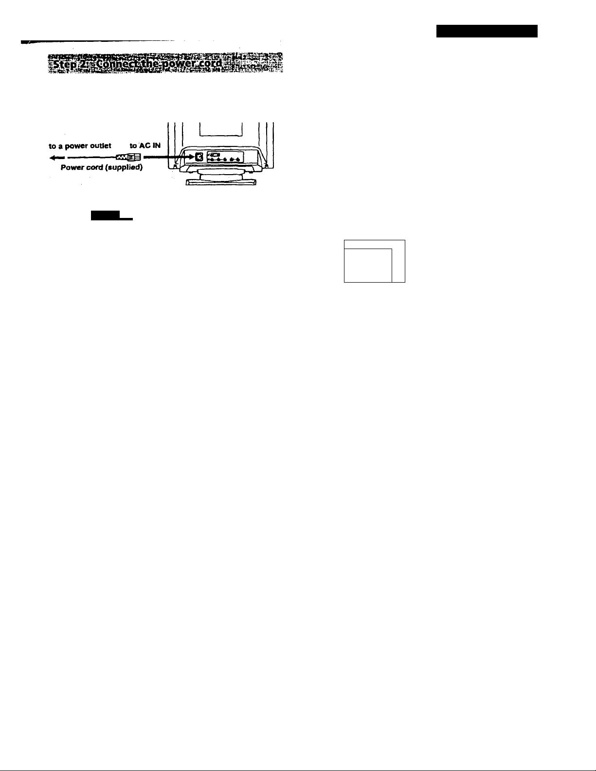
Wf
With the monitor switched off, connect one end of the
power cord to the monitor and the other end to a power
outlet
Getting Started
Automatically Adjusting the Size and Centering of the Picture
By pressing the auto sizing and centering (ASC) button, the
size and centering of the picture are automatically adjusted
to fit the screen.
1 Turn on the monitor and computer.
2 Press the ASC button.
The picture is adjusted to fit the center of the screen.
[ ASC \
The mstallation of your monitor is complete.
Note
If “OUT OF SCAN RANGE” or ”NO INFUT SIGNAL"
the screen, see "Warning Messages" on page 20
appears on
For customers using Windows* 95
Install the new model information from the "Wittdows 95 Monitor
Information Disk" into yoiir PC. (To iiutall the file, refer to the
attached "About the Windows 95 Moiutor Information Disk/File.")
This monitor complies with the "VESA DDC" Plug&Play standard.
If your PC/graphics board complies with DDC, select "Plug and
Play Monitor (VESA DDC)" as "Monitor type" from "Control
Panel" in Windows 9.5. Some PCs/graphics boards do not comply
with DDC- Even if your cdmputer complies wid\ DDC, it may have
some problems connecting with this monitor. In this case, select this
monitor's model name (GDM-4(X)P^ or CDM-SOOPS) as "Monitor
type" in Windows 9S.
For customers using Windows NT4.0
Monitor setup in Windows NT4.0 is different from Windows 95 and
does not involve the selection of monitor type. Refer to the
Windows NTAO instruction manual for further details on adjusting
the resolution, refresh rate, and number of colors.
s-'afl
Notes
• This function is intended for use with a computer running
Windows or similar graphic user interface software that
provides a full-screen picture. It may not work properly if the
background color is dark or if the input picture does not fill the
screen to the edges (such as an MS-DOS prompt).
• The screen may go blank for a few seconds while performing the
auto-sizing function. This is not a malfunction.
• Although the signals for picture aspect ratio 5:4 (resolution: 1280
X1024) do not fill the screen tn the edges, the picture is
accurately displayed.
Selecting the On-screen Display Language
If you need to change the OSD language, see "Using the
LANG (Language) On-screen Display" on page 17.
The default setting is English.
Page 8

Getting Started
Selecting the input Signal
This monitor has two signal input connectors (HD15 and
5BNC) and can be connected to two computers. When the
power of both computers is 6n, select the input signal you
want to view as follows.
2 Press the and ► buttons to select " ^
OPTION,“ and press the MENU button again.
The OPTION OSD appears.
1 Turn on the monitor and both computers.
2 Press the INPUT button to select the HD1S or 5BNC
input signal.
Each time you press tlie INPUT button, the input signal
and corresponding indicator alternate.
HD15 BNC
This monitor has two modes of input signal selection,
"AUTO" and "MANUAT.."
When "AUTO" is selected
If no sigrtal is input from the selected cormector, the monitor
automatically selects the other connector's signal When you
restart the computer you want to view, or that computer is
in power saving mode, the monitor may automatically
select the other connector's signal. This is because the
monitor switches from the interrupted signal to the constant
signal. If this happens, manually select the desired signal
using the INPUT button. ,
When "MANUAL" is selected
Even if no signal is input from the selected connector, the
monitor does not select the other connector's signal.
□ □
INPUT
b
3 Press the ■ii-f’/i' buttons to s^ect " Q (INPUT)."
b
4 Press the /-♦ buttons to select “AUTO" or
"MANUAL."
mm
b
The OPTION OSD automatically disappears after about 30
seconds.
To close the OSD, press the MENU button again.
For more information on using the OSD, see "Introducing
the On-screen Display System" on page 9.
1 Press the MENU button.
The MENU OSD appears.
MENU
8
■isSo^
1
im
SCREEN
Z<^M 1
□
COLOR
I gMm I
I e I e ei
I LANG I I SIZE 1 loPTlONl
Page 9

Customizing Your Monitor
Before adjusting
• Connect the monitor and the computer, and turn them on.
• Select “ @ LANG~ in the MENU OSD, then select
"ENGUSH'(see page 17).
Adjusting the Picture Brightness
and Contrast
Once the setting is adjusted, it will be stored in memory for
all input signals received.
1 Press the <i- (brightness) ■I’/f or 3 (contrast)
buttons.
The BRIGHTNESS/CONTRAST OSD appears.
S5 C0NTRa5iT
1 J
b b
a 26 o a 26 a
90.0kHz/ 7SHz
t-t
Horizontal Vertical
Frequency* Frequency*
2 For brightness adjustment
Press the buttons.
n-WTi ♦ .. . for more brightness
^ ... for less brightness
b
Introducing the On-screen Display System
Most adjustments are made using the MENU OSD.
MENU OSD
Press the MENU button to display the MENU OSD.
This MENU OSD eoritains links to the other OSDs described
below.
MENU
15
dl S COLOR
Displays the COLOR OSD for adjusting the color
temperature.
d] C3j center ,
Displays the CENTER OSD for adjusting the centering
of the picture.
For contrast adjustment
Press the buttons.
mm
. . . for more contrast
.. . for less contrast ,
b *■
The OSD automatically disappeais after about 3 seconds.
To reset, press the RESET button while the OSD is on. The
brightness and contrast arc both reset to the factory settings.
* The horizontal and vertical frequencies for dve received input
signal appear in the BRIGHTNESS/CONTRAST OSD.
m HID SCREEN
Displays the SCREEN OSD for adjusting the vertical
and horizontal convergence, etc.
[H 83 ZOOM
Displays the ZOOM OSD for enlarging and reducing
the picture.
[H e OPTION
Displays the OPTION OSD for adjusting the OSD
position and degaussing the screen, etc.
[H B SIZE
Displays the SIZE OSD for adjusting the picture size.
[7] Q LANG
Displays tlie LANGUAGE OSD for selecting the
language.
[8] O GEOM
Displays the GEOMETRY OSD for adjusting the picture
rotation and pincushion, etc.
m EXIT
Qoses the MENU OSD.
Page 10

Customizing Your Monitor
Using the CENTER On-screen Display
The CENTER sethngs allow you to adjust the centering of
the picture.
Once the setting is adjusted, it will be stored in memory for
the current input signal.
1 Press the MENU button.
The MENU OSD appears.
2 Press the and ► buttons to select “C3^
CENTER," and press the MENU button again.
The CENTER OSD appears.
EZD CZE]
I.
b b
3 For horizontal adjustment
Press the 0-4“/buttons.
.. to move the picture right
.. to mov« the picture left
b
0 26 a
Using the SIZE On-screen Display
The SIZE settings allow you to adjust the size of the picture.
Once the setting is adjusted, it will be stored in memory for
the current input signal.
1 Press the MENU button.
The MENU OSD appears.
2 Press the IjF'#’/'#’ and buttons to select “ Q
SIZE." and pre.ss the MENU button again.
The SIZE OSD appears.
t ^ I L^JL^J
b b
3 For horizontal adjustment
Press the 04—/*^ buttons.
mm
.. . to iixcrease picture size
... to decrease picture size
:\
0 ZS 0
b "
For vertical adjustment
Press the buttons.
For vertical adjustment
Press the buttons.
ij-
♦ ... to move the picture up
•^ ... to move the picture down
b
The OSD automatically disappears after about 30 seconds.
To close the OSD, press the MENU button again.
To reset, press the RESET button while the OSD is on.
The horizontal and vertical centerings are both reset to the
factory settings.
10
OZEl
♦ ... to increase picture size
♦ ... to decrease picture size
b
The OSD automatically disappears after, about 30 seconds.
To close the OSD, press the MENU button again.
To reset, press the RESET button while the OSD is on.
The horizontal and vertical sizes are both reset to the factory ■
settings.
Page 11
Using the ÇEOM (Geometry) On
screen Display
Customizing Your Monitor
4 Press the buttons to adjust the settings,
o
mim
TheGEOM (geometry) settings »How you to ac^ust the
shape and orientation of the picture.
Once the rotation is adjusted, it will be stored in memory for
all input signals received. All other adjustments will be
stored in memory for the current input signal.
1 Press the MENU button.
The MENU OSD appears.
MENU
2. Press the buttons to select " O
GEOM.' and press the MENU button again.
The GEOMETRY OSD appears.
c±zT] mm
b b
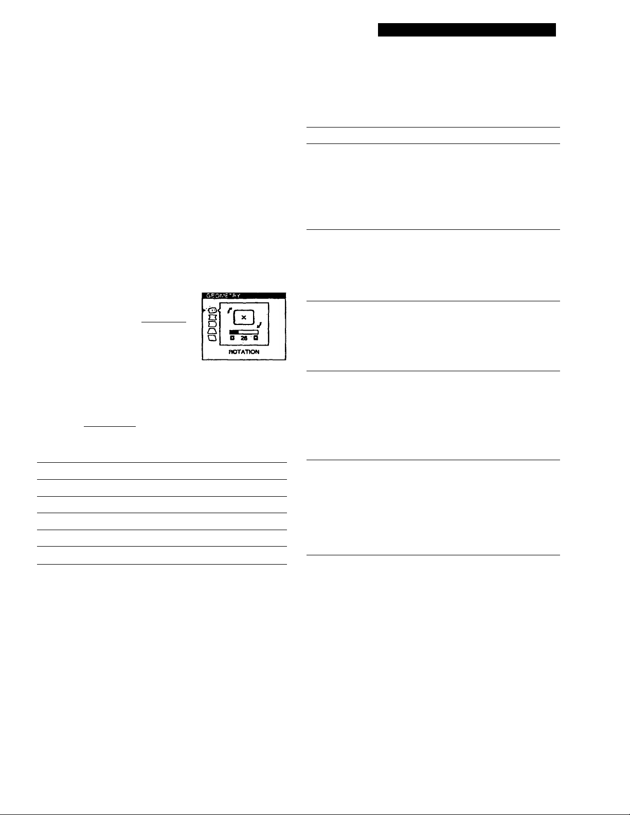
3 Press the buttons to select the item you want
to adjust.
For
O ROTATION
O PINCUSHION
D PIN BALANCE
r\ KEYSTONE
b
Press
. tu rotate llie picture clockwise
'Q,
. . .
to rotate the picture counterclockwise
.S'
. .
. to expand the picture sides
-o-
. to contract the picture sides
-n-
. to move the picture sides to the right
. to move the picture sides to the left
-a-
. to increase the plcmre width at the
top
Select
ROTATION
O
PINCUSHION
□
PIN BALANCE
D
KEYSTCB'IE
Û
KEY BALANCE
Q
1 ^ ^ I
b
To
adjust the picture rotation
adjust the picture sides
adjust the picture side balance
adjust the picture width
adjust the picture shape balance
'■O'
. to decrease the picture width at the
top
'O*'
O KEY BALANCE
The OSD automatically disappears after about 30 seconds.
To close the OSD, press the MENU button again.
To reset, press the RESET button while the OSD is on.
The selected item is reset to the factory setting.
. to move the top of the picture to
theright
'O'
. to move top o£ the picture to
the left
**n'
11
Page 12

Customizing Your Monitor
Using the ZOOM On-screen Display
The ZOOM settings allow you to enlarge or reduce the
picture.
Once the setting is adjusted, it will be stored in memory for
the current input signal.
1 Press the MENU button.
The MENU OSD appears.
2 Press the and buttons to select “ gg
ZOOM,*' and press the MENU button again.
The ZOOM OSD appears.
____
^ V
Em CZED
26
b b
3 Press the 34^/“^button$ to adjust the picture zoom.
Q
1 ^ 1
] ?.J ... to enlarge the picture
■4>“ ... to reduce the picture
73
b
The OSD automatically disappears after about 30 seconds.
To close the OSD, press the MENU button again.
To reset, press the RESET button while the OSD is on.
Note
The picture zoom adjustment will stop as soon as either the
horizuiilal or vertical size reaches its maximum or mirumum value.
Using the COLOR On-screen Display
You can change flie moiutor's color temperature. For
example, you can adjust or change the colors of a picture on
the screen to match the actual colms of the printed picture.
Once die setting is adjusted, it will be stored in memory for
all input signals received.
1 Press the MENU button.
The MENU OSD appears.
MENU
15
2 Press the and buttons to select "gj
COLOR," and press the MENÜ button again.
Tire COLOR OSD appears.
SPOOK I 6sooK| . 93oeK
I ^/LtJ GI
b
3 Press the buttons to select the color
temperature.
I » 11 I
im
b
R eiAsa
6 BIASO
B BIAS0
R GAM a
a CAINO
B GAIN D
a 50
a 50
a so
a so
a so
D SO
b
There are three color tempera ture modes in the OSD.
The preset adjustments are;
5000K, 6500K, 9300K
12
Page 13

4 Fine tuning the color temperature
Press the buttons to select ai\ item and adjust by
pressing the buttons.
Customizing Your Monitor
Using the SCREEN On-screen Display
asooKlnooK
швд/«ЖеЮИ$»в.'
I ^ 1 I ^ И I
ъ ъ
Select R (red), G (green), or B (blue) BIAS to adjust the
black level of each color's signal.
Select R (red), G (green), or B (blue) GAIN to .adjust the
while level of each color's signal.
The "SOOOK," "6500K" or "9300K" disappears and the
new color settings are memorized for each of the three
color modes.
The color temperature modes change as follows:
5000K-* 1, 6500K-* 2.9300K— 3
The OSD automatically disappeeurs after about 30 seconds.
To close the OSD, press the MENU button again.
To reset, press the RESET button while the OSD is on. The
selected item is reset to the factory settings.
G BIAS a BCD a so
в BiASBMEna fa
R GAINOBC^a so
G GAINDBEZia so
в GAIN в ned) a so
You can adjust convergence settings to eliminate red or blue
shadows that may appear around objects on the screen.
Adjust the CANCEL MOIRE function to eliminate wavy or
elliptical patterns that may appear on the screen.
Adjust the LANDING function to correct color imbalances
at the four comers of the screen due to influence from the
earth's magnetism.
Once CANCEL MOIRE is adjusted, it will be stored in
memory for the current input signal. All other adjustments
will be stored in memory for all input signals received.
1 Press the MENU button.
The MENU OSD appears.
MENU
2 Press the and buttons to select " QU)
SCREEN," and press the MENU button again.
The SCREEN OSD appears.
I 11 r
o" 26 D
H CONVEeGENCE
ъ ъ
§TOP
ЮВСГГ
□
о
3 Press the buttons to select the item you want
to adjust.
Ezzm
ъ
Select
m
H CONVERGENCE
(D
V CONVERGENCE
(Stop
VCONVERTOP
о вот
VeasrVER BOTTOM
To
adjust the horizontal convergence
adjust the vertical convergence
adjust the screen's upper vertical
convergence
adjust the screen's lower vertical
convergerux..
(continued)
13
Page 14

Customizing Your Monitor
Select
O
LANDING
a ADJ
LANDING ADJUST
H
CANCEL MOIRE •
O ADJ
MOIRE ADJUST
’ Moire is a type of natural interference which pioducessoft or
wavy lines on your screen. It may appear due to intezference
between the regulated pattern of the picture from theaipnt
signal and the phosphor pitch pattern of the CRT.
To
select one of the four comes that
needs color correction due lu
influence from the earth's magnetism
correct the color at one of the four
comers of the screen
turn the moire cancellation function
"ON" or "OFF." CANCELMOIRE
must be "ON" for " iQJ ADJ (MOIRE
ADJUST)” to appear on the screen.
adjust the degree of moire
cancellation
4 Press the buttons to adjust the settings.
For
gj BOT
V CONVER BOTTOM
□
LANDING
C3 ADJ
LANDING ADJUST
CANCEL MOIRE
liD!) ADJ
MOIRE ADHJST
Press
.. to shift red shadows up and blue
shadows down
E0
.. to shift red shadows down and
blue shadows up
S3
♦ or ■<“ ... to select the comer of the
screen you want to adjust
rn ; top left C3 t top right
CD : bottom left : bottom right
.. to reduce any irregularihes in
the color to a minimum
, to turn CANCEL MOIRE “ON”
j -OrF -OmD
■... to turn CANCEL MOIRE "OFF"
^ -Ofr -OM I
... to adjust the screen until the
moire is at a minimiim
E3ÌZ3
b
For Press
QD
H CONVERGENCE
d)
VCONVERGENCE
® TOP
VCONVERTOP
to sliift red shadows to the right
and blue shadows to the left
■SB*
to shift red shadows to the left
and blue shadows to the right
-TTi>
. to shift red shadows up and blue
shadows down
. to shift red shadows down and
blue shadows up
m
. to shift red shadows up and blue
»Itadows down
EB
. to shift red shadows down and
blue shadows up
EB
Note
The picture may become fuz2y when CANCEL MOIRE is set to
"ON."
The OSD automatically disappears after about 30 seconds.
To close the OSD, press the MENU button again.
To reset, press the RESET button while the OSD is on.
The selected item is reset to the factory setting.
14
Page 15
Using the OPTION On-screen
Customizing Your Monitor
Display
The OPTION OSD allows you to manually degauss the
screen and adjust settings such as the OSD position and
power saving delay time. It also allows you to lock the
controls.
ri-. r-'j if.
pisgaiissIniSi^ti^^
The monitor screen is automatically degaussed
(demagnetized) when the power.is turned on.
You can also manually degauss the. monitor.
1 Press the MENU button.
The MENU OSD appears.
MENU
2 Press the and buttons to select'
OPnON,' and press the MENU button again.
The OPTION OSD appears.
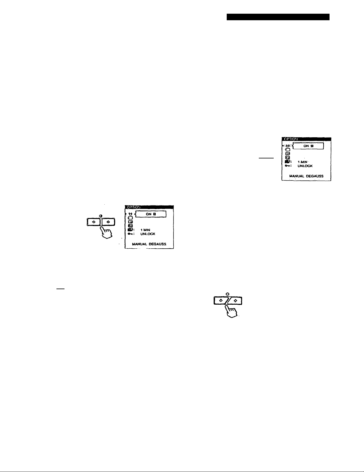
You can change the OSD position (for example, when you
want to adjust die picture behind the OSD).
1 Press the MENU button.
The MENU OSD appears.
2 Press the and buttons to select" i
OPTION,' and press the MENU button again.
The OPTION OSD appears.
QZD Bm
b b
3 Press the buttons to select" gg (OSD H
POSITION)'or ” O (OSD V POSITION).'
Select " gg (OSD H POSmQN)" to adjust the horizontal
position.
nZB
b
3 Press the buttons to select" (MANUAL
DEGAUSS).'
i 1
b
4 Press the O button.
The screen is degaussed for about 3 seconds.
Ezra
If you need to degauss the screen a second time, wait for at
least 20 minutes before repeating the steps above.
The OPTION OSD automatically disappears after about 30
seconds.
To close the OSD, press the MENU button again.
dZU
1 MIN
b
Select " (ig (OSD V POSITION)" to adjust the vertical
position.
4 Press the buttons to move the OSD to the
desired position.
0-: UNLOCK
OSD H POSITION
W
O: AUTO
S ,
___,--------
J3"(n H It D
-------
»y! UNLOCK
OSD V POSITION
!=!
------
,
'
turn
b
The OPTION OSD automatically disappears after about 30
seconds.
To close the OSD, press the MENU button again.
To reset, press the RESET button wliile the OSD is on.
15
Page 16

Customizing Your Monitor
You can set the delay time before the monitor enters the
power saving mode. Sec page 19 for more information on
thi.s monitor's power saving capabilities.
1 Press the MENU button.
The MENU OSD appears.
MENU
15
2 Press the and O^Z-P- buttons to select'
OPTION," and press the MENU button again.
The OPTION OSD appears.
rryn rncn
b b
3 Press the buttons to select - © (PWR SAVE
DELAY).“
n7/^
b
The control lock function disables all of the buttons on the
front panel except the C!) (power) switch, MENU and INPUT
buttons.
1 Press the MENU button.
The MENU OSD appears.
MENU
15
2 Press the and buttons to select " ^
OPTION," and press the MENU button again.
The OPTION OSD appears.
rrm c±TZ]
b b
3 Press the buttons to select "Oti (CONTROL
LOCK)."
ci
C): AUTO
S
(13
1 ^-UNLOCK- L0Ck|
CONTROL LOCK
4 Press the buttons to select the desired time.
i » il » i
b
When PWR SA\^ DELAY is set to "OFF," the monitor
does not go into power saving mode.
The OPTION OSD automatically disappears after about 30
seconds.
To close the OSD, press the MENU button again.
To reset, press the RESET button while the OSD is on.
16
4 Press the ► buttons to select "LOCK."
< » II o I
b
The OPTION OSD automatically disappears after about 30
seconds.
To close the OSD, press the MENU button again.
Once you select "LOCK," you carmot select any items
except "EXIT" and " ^1 OPTION" in the MENU OSD.
If you press any button other than the (1) (power) switch,
MENU and INPUT buttons, the On mark appears on the
screen.
To cancel the control lock
Repeat steps 1 through 3 above and press the
buttons to select "UNLOCK "
Page 17

Customizing Your Monitor
Using the LANG (Language) On
screen Display
EngKsh, French, German, Spanish, Italian and Japanese
versiot« of the OSDs are available.
1 Press the MENU button.
The MENU 0SD appears.
2 Press the and buttons to select “ @
LANG," and press the MENU button again.
The LANGUAGE OSD appears.
eCNOUaH .
FRANÇAIS
DEUTSCH
ESPAÑOL
b b
3 Press the buttons to select the desired
language.
nzn
ITALIANO
Resetting the Adjustments
1 Press the MENU. and O^-Z-^buttons to select
the OSD containing the item you want to reset.
a
Ofc] EZSZE!)
^ b b
2 Press the buttons to select the item you want
to reset.
1
b
3 Press the RESET button.
RESET
b
ENGLISH; English, FRANÇAIS: French,
DEUTSCH: German, ESPAÑOL; Spanish,
rrALIANO: Italian, or : Japanese.
The OSD automatically disappears after about 30 seconds.
To close the OSD, press the MENU button again.
To reset to English, press the RF.SET button while the OSD
is on. -
When there is no OSD displayed, press thé RESET
button.
All of the adjustments data for the current input signal is
reset to the factory settings.
Note that adjustment data not affected by changes in input
signal (OSD language; OSD position, input sigiul selection,
power saving delay time and the control lock function) is .
not reset to the factory settings.
RESET
Press and hold the RESET button for more than two
seconds.
All of the adjustment data, including the brightness and
contrast, is reset to the fгк;toty settings.
RESET
17
Page 18

Technical Features
Preset and User Modes
This monitor has factory preset modes for the most popular
industry standards for true "plug and play" compatibility.
When a new input signal is entered, the monitor selects the
appropriate factory preset mode and momentarily adjusts
the phase calibration to provide a high quality picture to the
center of the screen. The calibration is stored in memory
and is immediately recalled whenever ihc same input signal
is received.
Resolution Horizontal Vertical
(dots X lines) Frequency Frequency Graphics Mode
No.
640 x 350 31,5 kHz
1
640 x 480
2
640x480
3
6^x480
4
720 x 400
5
770 x 400
6
800 x 600
7
800 x 600 46.9 kHz 75 Hz ESVGA
8
800 x 600
9
832x624
10
1024x768
11
1024 x 768
12
1024 X 768
13
1024 x 768 60.2 kHz
14
1024 x 768
15
1152 x 864
16
1152 X 870 68.7 kHz 75 Hz . Macintosh
17
1280 x 960
18
1280 x 960
19
1280 x 1024
20
1280 X 1024 83.0 kHz
21
1280x1024
22
1600x1200
23
1600X1200
24
25 1600 X1200
26
1600x1200 93.8 kHz 75 Hz
27*
1600x1200
315 kHz 60 Hz VGA-G
37.5 kHz 75 Hz EVGA
43.3 kHz
31..“: kHz 70 Hz
37.9 kHz
37.9 kHz 60 Hz
53.7 kHz 85 Hz VESA
49.7 kHz
48.4 kHz
56.5 kHz
60.0 kHz
68.7kHz
675 kHz
60.0 kHz
85.9 kHz
64.0 kHz
91.1kHz
75.0 kHz 60 Hz VESA
81.3 kHz 65 Hz
875 kHz 70 Hz
1063 kHz
♦ GDM-500PS only
70 Hz MGGA
85 Hz
8SHz
75 Hz Macintosh
60 Hz VESA
70 Hz VESA
75 Hz
75 Hz Macintosh
-85 Hz
75 Hz VESA
60 Hz
85 Hz
60 Hz VESA
75 Hz VESA
85Hz
85 Hz
VESA
VGA-Texl
VESA
SVGA
16" Color
EUVGA
19" Color
VESA
21" Color
VESA
VESA
VESA
VESA
VESA
VESA
VESA
For input signals that do not match one of the factory preset
modes, the ¿gital Multiscan technology of this monitor
performs all of the adjustments necessary to ensure that a
clear picture app>ears on the screen for any timing in the
monitor's frequency range. However, it may be necessary
to fine tune the vertical/horizontal size and centering.
Simply press the ASC button or adjust the monitor
according to the adjustment instructior\s. The adjustments
are stored automatically as a user mode and recalled
whenever the corresponding input signal is received. A
total of 15 user adjusted modes can be stored in memory,
including those made with the ASC button. If a 16th mode
is entered, it will replace the first.
Recommended horizontal and vertical timing conditions
Horizontal sync width duty should be; >4.8% of total horizontal
time.
Horizontal blanking width should be; >25 psec.
Vertical blanking width should be; > 450 psec.
Note for Windows* users
For Windows users, check your video board manual or the utility
program which comes with your graphic board and select the
highest available refresh rate to maximize monitor performance.
Adjusting the monitor's resolution and color number
If you are using Windows 95, adjust the monitor's :
resolution and color number according to the steps below.
Refer also to the Windows 95 HELP files.
If you are using a Macintosh or compatible computer. Refer
to your computer's instruction manual.
1 Click the Start button and point to Settings. Then
double-click the Control Panel.
2 Double-click the Display icon.
3 Click Settings.
4 Click the Color palette. Point to the desired color
number and click.
Point to the Desktop area and drag the slider to the
desired resolution.
5 Click OK.
Note
Some settings may require that the computer be turned off then
back cm to taVe effect. In thi.s ra.xe, follow the on-screen instructions.
About'the color number
• The Color palette setting and the actual number uf colors is as
follows;
High Color (16 bit) —• 65536 colors
True Color (24 bit) —» about 1,677 million colors
• In True color mode (24 bit), speed may be slower.
• The color number may vary accordirtg to your computer or
video board.
18
Page 19

Power Saving Function
This monitor meets the power-saving guidelines set by
VESA and Energy Star, as well as the more stringent
NUTEK.
If the monitor is connected to a computer or video graphics
board that is VESA DPMS (Display Power Management
Signaling) compliant, the monitor will automatically reduce
power consumption in three stages as shown below.
You can set the delay time before die monitor enters the
power saving mode using the OSD. Set dre time according
to "Setting the power saving delay time" on page 16.
Note
If no video signal is input to the monitor, the "NO INPUT
SIGNAL" message (page 20) appears. After the delay time has
passed, the power saving function autcnnatlcaUy puts the morvitor
into the active-off mode and the Ò indicator lights up orange. Once
the horizontal and vertical sync signals are detected, the monitor
automatically resumes its normal operation mode.
Power consumption
mode
Normal op>eration
1
Standby (1st mode)
2
Suspend (2nd mode)
3
Active-off (3rd mode)
4
Power-off
5
Screen
actíve
blank
blank
blank
—
Horizontal
sync signal
present
absent
present
absent
—
Vertical
sync signal
present
present
absent
absent
—
Damper Wires
When viewing a white background, very thin horizontal
tines may be visible on the screen as shown below. These
lines are the shadows of the damper wires and are
characteristic of CRTs that use aperture grilles. The wires
are attached to the aperture grille on the inside of the
Trinitron tube and prevent the vibration of the aperture
grille.
Damper wires
Power consumption
S160W (GDM-500PS)
S130 W (GDM-400PS)
S 100 W (CDM-500PS)
S85W(GDM-400PS)
S15W
S5W Approx. 10 sec.
OW
Recovery time
Approx. 3 sec.
Approx. 3 sec.
—
d) indicator
Green
Green and orange
alternate
Green and orange
alternate
Orange
Off
Plug & Play
This monitor complies with the DDC"*1, DDC2B, DDC2AB
and DDC2B+ Display Data Channel (DDC) standards of
VESA.
When a DDCl host system is connected, the monitor
synchronizes with the V. CLK in accordance with the VESA
standards and outputs the EDID (Extended Display
Identification Data) to the data line.
When a DDC2B, DDC2AB or DDC2B+ host system is
connected, the monitor automatically switches to the
appropriate standard.
DDC"* is a trademark of the Video Electronics Standard
Association.
Note
When using Windows* 95, the DDC standard docs not apply to ihe
5 BNC connectors. If you use the DDC standard, connect the HD15
connector to the computer with the supplied video signal cable.
19
Page 20

Additional Information
m The input signal condition
Warning Messages
If there is something wrong with the input signal, one of the
following messages appears.
"OUT OF SCAN RANGE" indicates that the input signal
is not supported by the moiutor's specifications.
"NO INPUT SIGNAL" indicates that no signal is input, or
the input signal from the selected input connector is not
©INFORMATION
pfl—4|oUT OF SCAN range!
[2]
------
^INPLfT : HDlT|
received.
[2I The selected input connector
Indicates which input connector is receiving the wrong
signal. If there is something wrong with the signal from
both input connectors, "HD15" and "BNC" are
displayed alternately.
To solve these problems, see "Troubleshooting" below.
Troubleshooting
This section may help you isolate the cause of a problem and as a result, eliminate the need to contact technical support.
Symptom
'I!
No picture
If the C!) indicator is not lit
If the "NO INHJT SIGNAL"
message appears on the screen,
or if the C!) indicator is cither
orange or alternating between
green and orange
If the "OUT OF SCAN RANGE"
message appears on the screen
If no message is displayed and
the (!) indicator is green or
flashing orange
If using a Macintosh system
If using Windows* 95
Picture is scrambled
Check these items
• Check that the power cord is properly connected.
• Check that the Cl) (power) switch is in the "on" position.
• The screen is blank when the monitor is in power saving mode. Try pressing any key on the
computer keyboard.
• Check that your computer power switch is in the "on" position.
• Check that the input select setting is correct.
• Check that the video signal cable is properly connected and all plugs are firmly seated in
their sockets.
• Check that the 5 BN<Z!s are connected in the correct order (from left to right; Red-GreenBlue-HD-VD) (page 6).
• Ensure that no pins are bent or pushed in the HD15 video input connector.
• Check that the video board is completely seated in the proper bus slot.
• Check that the video frequency range is within that specified for the monitor.
Horizontal; 30 - 94 kHz (GDM-400PS), 30 -107 kl Iz (GDM-500PS)
Vertical; 48 -160 Hz
Refer to your computer's instruction manual to adjust the video frequency range.
• If you are using a video signal cable adapter, check that it is correct.
• See "Self-diagnosis Function" (page 22).
• Check that the Macintosh adapter and the video signal cable are properly connected (page
6).
• If you cannot find your model's name (GDM-400PS or GDM-500PS) among the Sony
monitors in the Windows 95 monitor selection screen, select the DDC standard monitor or
install the Windows 95 Monitor Information Disk (page 7).
The DDC standard does not apply to the 5 BNC connectors. If you use the DDC standard,
connect the computer to the HD15 connector with the supplied video signal cable.
• Check your graphics board manual for the proper monitor setting.
• Check this manual and confirm that the graphics mode and the frequency you are trying to
operate at is supported. Even if the frequency is within the proper range, some video
boards may have a sync pulse that Is too narrow for the monitor to sync correctly.
20
Page 21

Additional Information
Symptom
Color is not uniform
You cannot adjust the monitor
with the buttons on the front
panel
White does not look white
Screen image is not centered or
sized properly
Edges of the image are curved
White lines show red or blue
shadows at edges
Picture is fuzzy
Picture bounces or has wavy
oscillations
Check these items
• Degauss the morütor (page 15).
If you place equipment which generates a magnetic field, such as a loudspeaker, near the
moivitOr, or you change the direction of thé monitor, color may lose uniformity.
The degauss function demagnetizes the metal frame of the CRT to obtain a neutral field for
uniform color reproduction. If a second degauss cycle is needed, allow a mirümum interval
of 20 minutes for the best result.
• Adjust the landing (pages 13 -14).
• If the control lock function is set to on, set it to off using the OPTION OSD (page 16).
• Adjust the color temperature (pages 12 -13).
• Check that the 5 BNCs are connected in the correct order (from left to right: Red-GreenBlue-HD-VD) (page 6).
• Press the ASC button (page 7).
• Adjust the size or centering (page 10).
• Sòme video modes dò not fill the screen to the edges. This problem tends to occur with
certain video boards.
• Adjust the geometry (page 11).
• Adjust the convergence (pages 13 -14).
• Adjust the contrast and brightness (page 9).
• Degauss the monitor (page 15).
If you place equipment which generates a magnetic field, such as a loudspeaker, near the
ihonitor, or you change the direction of the monitor, color may lose uniformity.
The degauss function demagnetizes the metal frame of the CRT to obtain a neutral field for
uniform color rejjroduction. if a second degauss cycle is needed, allow a minimum interval
of 20 minutes for the best resul l.
• If red or blue shadows appear along the edges of images, adjust the convergence
(pages 13 -14).
• If the moire is cancelled, the picture may become fuzzy. Decrease the moire cancellation
effect (pages 13 -14).
; Isolale and eliminate any potential sources of electric or magnetic fields. Common causes
for this symptom are electric fans, fluorescent lighting or laser printers.
• If you have another monitor close to this monitor, increase the distance between them to
reduce the interference.
• Try plugging the monitor into a different AC outlet, preferably on a different circuit.
• Try the monitor on a different computer in a different room.
Picture.is flickering
Picture appears to be ghosting • Eliminate the use of video cable extensions and/or video switch boxes if this symptom
Wavy or elliptical (moire)
pattern is visible
Two fine horizontal lines • These wires stabilize the vertically striped aperture grille'(page 19). This aperture grille
(wires) are visible
Hum is heard right after the
power is turned on
• Set the refresh rate on the computer to obtain the best possible picture by referring to the
computer’s manual.
occurs. Excessive cable length or a weak connection can produce this s}miptom.
• Cancel the moire (pages 13 -14).
The moire may be modified depending on the corinectcd computer.
• Due to the relationship between resolution, monitor dot pitch and the pitch of some image
patterns, certain screen backgrounds sometimes show moire. Change your desktop pattern.
allows more light to pass through to the screen givirrg the Trinitron CRT more color and
brightness.
• When the power is turned on, the auto-degauss cycle is activated. While the auto-degauss
cycle is activated (3 seconds), a hum may be heard. The same hum is heard when the
monitor is manually degaussed. Tliis is not a malfunction.
21
Page 22

Additional Information
Self-diagnosis Function
This monitor is equipped with a self-diagnosis function. If
there is a problem with your monitor or computer(s), the
screen will go blank and the (1) indicator will either light up
green or fla.sh orange.
0 Indicator
If the C!) indicator is green
1 Remove any plugs from the video Input 1 and 2
connectors, or turn off the connected computer(s).
2 Press and hold the 9-*^ button for 2 seconds.
a
If all four color bars appear (wliite, red, green, blue), the
monitor is working properly. Reconnect the video input
cables and check the condition of your computer(s).
If the color bars do not app>ear, there is a potential
monitor failure. Inform your authorized Sony dealer of
the monitor's condition.
If the Cb indicator is flashing orange
Press the 0 button to turn the monitor off and on.
If the (!) indicator lights itp green, the monitor is
working properly.
If the Ô indicator is istill flashing, there is a potential
monitor failure. Count the number of seconds between
orangé flashes of the Ô indicator and inform your
authorized Sony dealer of the morütor's condition. Be
sure to note the model name and serial number of your
monitor. Also note the make and model of your
computer and video board.
Specifications
GDM-400PS
Picture tube
Viewable image size
Resolution
Standard image area
Deflection frequency
AC input voltage/current
Power consumption
Dimensions
Mass
Supplied accessories
GDM-500PS
Picture tube
Viewable image size
Resolution
Standard image area
Deflection frequency
AC input voltage/current
Power consumption
Dimensions
Mass ,
Supplied accessories
0.25 - 0.27 mm aperture grille pitch
19 inches measured diagonally
90-degree deflection
Approx. 365 X 273 mm (w/h)
(14 ^/a X 10 ^/4 inches)
18.0" viewing image
Horizontal; Max. 1600 dots
Vertical; Max. 1200 lines
Approx. 330 X 264 mm (vv/h)
(13 X 10 V2 inches)
Approx. 352 X 264 mm (w/h)
(13 ^/a X 10 Vj inches)
Horizontal; 30 to 94 kHz
Vertical: 48 to 160 Hz
100 to 240 V, 50 - 60 Hz, 1.8 - 1.0 A
Max. 130 W
444 X 467 X 453 mm (w/h/d)
(17 V2 X 18 V2 X 17 7/g inches)
Approx. 25 kg (55 lb 2 oz)
See page 6
0.25 — 0.27 mm aperture grille pitch
21 inches measured diagonally
90-degree deflection
Approx. 403.8 X 302.2 mm (w/h)
(16 X 12 inches)
19.8" viewing image
Horizorital: Max. 1600 dots
Vertical; Max. 1200 lines
Approx. 388 X 291 mm (w/h)
(15 ^/a X 11 */2 inches)
or
Approx. 364 X 291 mm (w/h)
(14 ^/a X 11 ’/2 inches)
Horizontal: 30 to 107 kHz
Vertical; 48 to 160 Hz
100 to 240 V, 50 - 60 Hz, 2.0 - 1.0 A
Max. 160 W
498 X 505 X 474 mm (w/h/d)
(19 */a X 20 X 18 ^/4 inches)
Approx. 31 kg (68 lb 5 oz)
See page 6
22
Design and specifications are subject to change without
notice.
 Loading...