

Page 1
2-890-214-03(1)
FWD-40LX2F/40LX2X/32LX2F/32LX2X
Flat Wide Display
Monitor
取扱説明書
Operating Instructions
Mode d’emploi
Bedienungsanleitung
Manual de instrucciones
Istruzioni per l’uso
JP
GB
FR
DE
ES
IT
CS
Sony Corporation Printed in China
お買い上げいただきありがとうございます。
電気製品は安全のための注意事項を守らないと、
火災や人身事故になることがあります。
この取扱説明書には、事故を防ぐための重要な注意事項と製品の取
り扱いかたを示してあります。この取扱説明書をよくお読みのうえ、
製品を安全にお使いください。お読みになったあとは、いつでも見
られるところに必ず保管してください。
FWD-40LX2F/40LX2X/32LX2F/32LX2X
© 2006 Sony Corporation
Page 2
安全のために
ソニー製品は安全に充分配慮して設計されています。しかし、電気
製品は、まちがった使いかたをすると、火災や感電などにより死亡
や大けがなど人身事故につながることがあり、危険です。
事故を防ぐために次のことを必ずお守りください。
安全のための注意事項を守る
4 〜 7 ページの注意事項をよくお読みください。
8 ページの「本機の性能を保持するために」もあわせてお読みくだ
さい。
定期点検をする
5 年に 1 度は、内部の点検を、お買い上げ店またはソニーのサービ
ス窓口にご依頼ください(有料)。
故障したら使わない
すぐに、お買い上げ店またはソニーのサービス窓口にご連絡くださ
い。
万一、異常が起きたら
・ 煙が出たら
・ 異常な音、におい
がしたら
・ 内部に水、異物が
入ったら
・ 製品を落としたり
キャビネットを破
損したときは
1 ディスプレイの電源を切る。
2 ディスプレイの電源コードや
,
接続コードを抜く。
3 お買い上げ店またはソニーの
サービス窓口に連絡する。
警告表示の意味
取扱説明書および製品で
は、次のような表示をして
います。表示の内容をよく
理解してから本文をお読み
ください。
この表示の注意事項を守ら
ないと、火災や感電などに
より死亡や大けがなど人身
事故につながることがあり
ます。
この表示の注意事項を守ら
ないと、感電やその他の事
故によりけがをしたり周辺
の物品に損害を与えたりす
ることがあります。
注意を促す記号
行為を禁止する記号
この装置は、情報処理装置等電波障害自主規制協議会(VCCI)の基準
に基づくクラス B 情報技術装置です。この装置は、家庭環境で使用す
ることを目的としていますが、この装置がラジオやテレビジョン受信
機に近接して使用されると、受信障害を引き起こすことがあります。
取扱説明書に従って正しい取り扱いをしてください。
JP
2
行為を指示する記号
Page 3

目次
警告..............................................................................................................................................4
注意..............................................................................................................................................5
電池についての安全上のご注意......................................................................................................7
本機の性能を保持するために..........................................................................................................8
設置するときのご注意 ..................................................................................................................10
各部の名称と働き
前面パネル......................................................................................................................................11
サイドパネル..................................................................................................................................12
オプションアダプター ..................................................................................................................14
後面パネル......................................................................................................................................15
リモコン..........................................................................................................................................16
ボタンの機能 ............................................................................................................................ 16
リモコンの特別ボタン.............................................................................................................18
ワイド切換を使う ...............................................................................................................18
2 画面設定を使う ...............................................................................................................19
IDMODE ボタンを使う....................................................................................................20
ECO モード機能を使う......................................................................................................20
JP
接続
スピーカーの接続 ..........................................................................................................................21
電源コードの接続 ..........................................................................................................................21
ケーブルを処理する ......................................................................................................................22
メニューの設定
メニュー一覧..................................................................................................................................24
画質メニュー..................................................................................................................................26
音質メニュー..................................................................................................................................28
画面調整メニュー ..........................................................................................................................29
設定メニュー..................................................................................................................................33
その他の情報
故障かな?と思ったら ..................................................................................................................36
入力信号一覧表..............................................................................................................................38
仕様 .................................................................................................................................................39
索引 .................................................................................................................................................41
JP
3
Page 4
警告
下記の注意を守らないと、火災や感
電
により死亡や大けがにつながる
ことがあります。
内部に水や異物をいれない
水や異物が入ると火災や感電の
原因となることがあります。
万一、水や異物が入ったときは、
すぐに電源を切り、電源コード
や接続コードを抜いて、お買い
上げ店またはソニーのサービス
窓口にご相談ください。
規定の電源電圧で使う
この取扱説明書に記されている
電源電圧でお使いください。
規定外の電源電圧での使用は、
火災や感電の原因となります。
油煙、湯気、湿気、ほこりの多い場
所では設置・使用しない
上記のような場所に設置すると、
火災や感電の原因となります。
この取扱説明書に記されている
仕様条件以外の環境での使用は、
火災や感電の原因となります。
分解や改造をしない
分解や改造をすると、火災や感
電、けがの原因となることがあ
ります。
内部の点検や修理は、お買い上
げ店またはソニーのサービス窓
口にご依頼ください。
電源コードを傷つけない
電源コードを傷つけると、火災や
感電の原因となります。次の項目
を必ずお守りください。
・設置時に、製品と壁やラック、
棚などの間に、はさみ込まな
い。
・電源コードを加工したり、傷つ
けたりしない。
・重いものをのせたり、引っ張っ
たりしない。
・熱器具に近づけたり、加熱した
りしない。
・電源コードを抜くときは、必ず
プラグを持って抜く。
万一、電源コードが傷んだら、お
買い上げ店またはソニーのサービ
ス窓口に交換をご依頼ください。
設置・取り付けは確実に
不確実な設置を行うと、ディス
プレイが転倒してけがや火災・
感電の原因となります。設置の
際は、以下の注意事項を必ずお
守りください。
壁面・天井・台上への設置、ま
たは転倒防止のためディスプレ
イを固定するなど、特殊な設置
を行う場合には、必ずお買い上
げ店に工事を依頼してください。
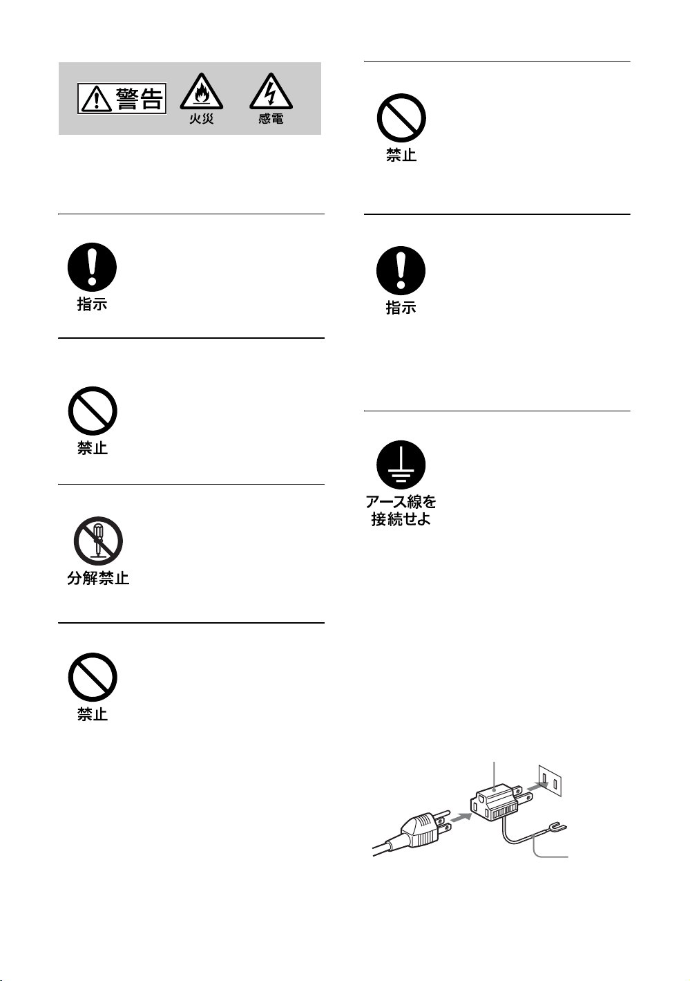
安全アースを接続する
安全アースを接続しないと、感
電の原因となることがあります。
次の方法でアースを接続してく
ださい。
・電源コンセントが 3 極の場合
付属の電源コードを使用するこ
とで、安全アースが接続されま
す。
・電源コンセントが 2 極の場合
付属の 3 極→2 極の変換プラグ
アダプターを使用し、変換プラ
グアダプターから出ている緑色
のアースを、建物に備えられて
いるアース端子に接続する。
・アース接続は、必ず電源プラグ
を電源につなぐ前に行ってくだ
さい。また、アース接続をはず
す場合は、必ず電源プラグを電
源から切り離してから行ってく
ださい。
変換プラグアダプター
アース線
不明な点はお買い上げ店またはソ
ニーのサービス窓口にご相談くだ
さい。
JP
4
Page 5
高温部分に触れない
機器を使用中または使用直後に
は上面や側面が高温になってい
るため、やけどをすることがあ
ります。
使用中および電源を切るまたは
スタンバイした状態から 10 分間
は触れないでください。
注意
下記の注意を守らないと、けがをし
たり周辺の物品に
があります。
重いディスプレイは、2 人以上で開
梱・運搬する
損害を与えること
ディスプレイは見た目より重量
があります。開梱・運搬は、け
がや事故を防ぐため、必ず 2 人
以上で行ってください。1 人で行
うと腰を痛めることがあります。
不安定な場所に設置しない
ぐらついた台の上や傾いたとこ
ろなどに設置すると、ディスプ
レイが落ちたり、倒れたりして、
けがの原因となることがありま
す。
また、設置・取り付け場所の強
度を充分にお確かめください。
接続の際は電源を切る
電源コードや接続ケーブルを接
続するときは、電源を切ってく
ださい。感電や故障の原因とな
ることがあります。
指定された電源コード、接続ケーブ
ルを使う
付属の、あるいは取扱説明書に
記されている電源コード、接続
ケーブルを使わないと、感電や
故障の原因となることがありま
す。
ほかの電源コードや接続ケーブ
ルを使用する場合は、お買い上
げ店またはソニーのサービス窓
口にご相談ください。
JP
本体を持って運搬する
ディスプレイを運ぶときは、ス
ピーカー部分を持たず、必ず本
体を持ってください。スピー
カーがディスプレイからはずれ
て落下し、けがの原因となるこ
とがあります。
ぬれた手で電源プラグをさわらない
ぬれた手で電源プラグを抜き差
しすると、感電の原因となるこ
とがあります。
水のある場所に設置しない
水が入ったり、ぬれたりすると、
火災や感電の原因となることが
あります。雨天や降雪中、海岸
や水辺での使用は特にご注意く
ださい。
通風孔をふさがない
通風孔をふさぐと内部に熱がこ
もり、火災や故障の原因となる
ことがあります。風通しをよく
するために次の項目をお守りく
ださい。
・ 設置の項(10 ページ)に従っ
て設置してください。
・ 密閉された狭い場所に押し込
めない。
・ 毛足の長い敷物(じゅうたん
や布団など)の上に設置しな
い。
・ 布などで包まない。
・ あお向けや横倒し、逆さまに
しない。
設置時には必ずスタンドを使用する
ディスプレイの転倒によるけが
や事故を防ぐため、台・床など
に本機を据え置きする際は、別
売の専用スタンドをご使用くだ
さい。
JP
5
Page 6
設置時には転倒防止処置を行う
本機を据え置きする際には、万
一の場合に備え、転倒防止処置
を行ってください。
直射日光の当たる場所や熱器具の近
くに設置・保管しない
内部の温度が上がり、火災や故
障の原因となることがあります。
電源コードのプラグおよびコネク
ターは突き当たるまで差し込む
まっすぐに突き当たるまで差し
込まないと、火災や感電の原因
となります。
お手入れの際は、電源を切って電源
プラグを抜く
電源を接続したままお手入れを
すると、感電の原因となること
があります。
定期的に内部の掃除を依頼する
長い間、掃除をしないと内部に
ホコリがたまり、火災や感電の
原因となることがあります。1 年
に 1 度は、内部の掃除をお買い
上げ店またはソニーのサービス
窓口にご依頼ください(有料)。
特に、湿気の多くなる梅雨の前
に掃除をすると、より効果的で
す。
人が通行するような場所に置かない
コード類は正しく配置する
電源コードや信号ケーブルは、
足に引っかけると製品の落下や
転倒などによりけがの原因とな
ることがあります。人が踏んだ
り、引っかけたりするような恐
れのある場所を避け、十分注意
して接続・配置してください。
コード類は正しく配置する
電源コードや接続ケーブルは、
足に引っかけると本機の落下や
転倒などによりけがの原因とな
ることがあります。
十分注意して接続・配置してく
ださい。
変換プラグアダプターのアース
キャップは幼児の手の届かないとこ
ろに保管する
万一、誤って飲み込んだときは、
窒息する恐れがありますので、
ただちに医師にご相談ください。
移動させるときは電源コード、接続
ケーブルを抜く
接続したまま移動させると、電
源コードや接続ケーブルが傷つ
き、火災や感電の原因となるこ
とがあります。
JP
6
Page 7
電池についての安全
上のご注意
液漏れ・破裂・発熱による大けがや
失明を避けるため、下記の注意事項
を必ずお守りください。
下記の注意事項を
守らないと、破
裂・発熱・液漏れ
により、死亡や大けがなどの人身事
故になることがあります。
電池の液が漏れたときは
素手で液をさわらない
電池の液が目に入ったり、身体や
衣服につくと、失明やけが、皮膚
の炎症の原因となることがありま
す。液の化学変化により、時間が
たってから症状が現れることがあ
ります。
必ず次の処理をする
液が目に入ったときは、目をこす
らず、すぐに水道水などのきれい
な水で充分洗い、ただちに医師の
治療を受けてください。
液が身体や衣服についたときは、
すぐにきれいな水で充分洗い流し
てください。皮膚の炎症やけがの
症状があるときは、医師に相談し
てください。
電池は乳幼児の手の届か
ない所に置く
電池は飲み込むと、窒息や胃など
への障害の原因となることがあり
ます。
万一、飲み込んだときは、ただち
に医師に相談してください。
下記の注意事項を
守らないと、破
裂・液漏れによ
り、けがをしたり周辺の物品に損害
を与えたりすることがあります。
指定以外の電池を使わな
い、新しい電池と使用し
た電池または種類の違う
電池を混ぜて使わない
電池の性能の違いにより、破裂し
たり、液が漏れたりして、けがや
やけどの原因となることがありま
す。
マンガン電池をお使いください。
電池の品番を確かめ、お使いくだ
さい。
+と−の向きを正しく入
れる
+と−を逆に入れると、ショート
して電池が発熱や破裂をしたり、
液が漏れたりして、けがややけど
の原因となることがあります。
機器の表示に合わせて、正しく入
れてください。
JP
使用済みの電池は、地域の
ルールに従って処分してく
ださい。
電池を火の中に入れない、
加熱・分解・改造・充電
しない、水でぬらさない
破裂したり、液が漏れたりして、
けがややけどの原因となることが
あります。
使い切ったときや、長時
間使用しないときは、電
池を取り出す
電池を入れたままにしておくと、
過放電により液が漏れ、けがやや
けどの原因となることがあります。
リモコンのフタを開けて
使用しない
リモコンのフタを開けたまま使用
すると、漏液、発熱、発火、破裂
などの原因となることがあります。
マンガン電池を使用し、フタを閉
めて使用してください。
7
JP
Page 8

本機の性能を保持す
るために
液晶パネルについて
・ 画面上に赤や青、緑の点(輝点)が消えな
かったり、黒い点(滅点)がある場合があり
ますが、故障ではありません。パネルは非常
に精密な技術で作られており、ごくわずかの
画素欠けや常時点灯する画素がある場合があ
ります。ご了承ください。
・ 液晶画面を太陽に向けたままにすると、液晶
画面を傷めてしまいます。窓際や室外に置く
ときなどはご注意ください。
・ 前面のフィルターを強く押したり、ひっかい
たり、上にものを置いたりしないでくださ
い。画面にムラが出たり、液晶パネルの故障
の原因になります。
・ 寒い所でご使用になると、画像が尾を引いて
見えたり、画面が暗く見えたりすることがあ
りますが、故障ではありません。温度が上が
ると元に戻ります。
・ 静止画を継続的に表示した場合、残像を生じ
ることがありますが、表示内容を変えたり、
画面全体を白表示にすることで徐々に解消さ
れます。なお、長期にわたり同じ表示を続け
た場合は、元に戻らなくなることがあります
ので、ご注意ください。
・ 使用中に画面やキャビネットが温かくなるこ
とがありますが、故障ではありません。
設置についてのご注意
ほかの機器と組み合わせて設置する場合、各機
器の設置位置などにより、リモコンの誤動作や
映像の乱れ、雑音などが起こることがありま
す。この場合は、お買い上げ店、またはソニー
のサービス窓口にご連絡ください。
ディスプレイのお手入れについて
スクリーン面の汚れは
・ お手入れをする前に、必ず電源プラグをコン
セントから抜いてください。
・ 液晶の画面は特殊加工がされていますので、
なるべく画面に触れないようにしてくださ
い。また画面の汚れを拭きとるときは、乾い
た柔らかい布で拭きとってください。
・ アルコールやシンナー、ベンジンなどは使わ
ないでください。変質したり、塗装がはげた
りすることがあります。
・ 化学ぞうきんをご使用の際は、その注意書き
に従ってください。
・ 殺虫剤のような揮発性のものをかけたり、ゴ
ムやビニール製品に長時間接触させると、変
質したり、塗装がはげたりすることがありま
す。
外装の汚れは
・ 乾いた柔らかい布で軽く拭いてください。汚
れがひどいときは、薄い中性洗剤溶液を少し
含ませた布で拭きとり、乾いた布でから拭き
してください。
・ アルコールやベンジン、シンナー、殺虫剤な
どは使わないでください。表面の仕上げを傷
めたり、表示が消えてしまうことがありま
す。
ディスプレイ表面の取扱いについて
のご注意
ディスプレイの表面は傷つきやすいので、硬い
ものでこすったり、たたいたり、ものをぶつけ
たりしないでください。
JP
8
Page 9

電源接続時のご注意
それぞれの地域に合った電源コードをお使いください。
アメリカ合衆国、
カナダ
プラグ型名 VM0233 COX-07 636
コネクタ型名 VM0089 COX-02 VM0310B VM0303B VM1313
コード型名 SVT H05VV-F CEE(13)53rd(O.C) HVCTF
定格電圧・電流 10A/125V 10A/250V 10A/250V 10A/125V
安全規格 UL/CSA VDE VDE 電安法
1)プラグに関しては各国・地域規制に適合し、使用に適した定格のものを使用してください。
ヨーロッパ諸国
イギリス、アイルランド、オー
ストラリア、ニュージーランド
1)
–
日本
VM1296
JP
JP
9
Page 10
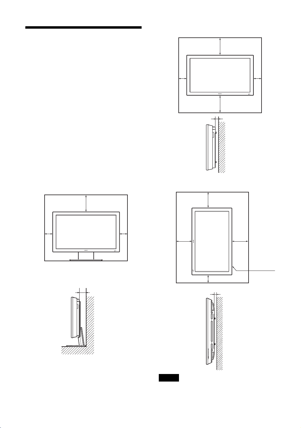
設置するときのご注
意
水平方向で使用する場合
前面
25
周囲に充分なスペースをとる
・ 内部の温度上昇を防ぐため、密閉状態にならないよ
うにディスプレイの周囲に少なくとも下図に示す距
離をあけて、通風を確保してください。
・ 周囲の温度は 0℃〜 35℃の範囲でご使用ください。
・ スタンドを使用するときは、必ず専用ディスプレイ
スタンド SU-42FW/32FW(別売)をご使用くださ
い。
・ ブラケットやネジ、ボルトなどの設置機材について
特定の製品を指定することはできません。実際の設
置は、お買い上げ店またはソニーのサービス窓口に
ご依頼ください。設置についてはソニーのサービス
窓口にご相談ください。
・ 通電中は高温になる部分があり、やけどの原因とな
ります。通電中やスタンバイにした直後は、本機の
上面、後面には手を触れないでください。
ディスプレイスタンドを使用する場合
前面
20
10
10
10 10
25
側面
垂直方向で使用する場合
前面
20
25
5
単位:cm
25
設置の際
は、必ず1
POWER
(パワー)
スイッチを
右下にして
ください。
10
側面
JP
10
単位:cm
10
側面
ご注意
本機を垂直方向で使用するときは、スピーカー SSSP40FW/32FW(別売)は使用できません。
5
単位:cm
Page 11
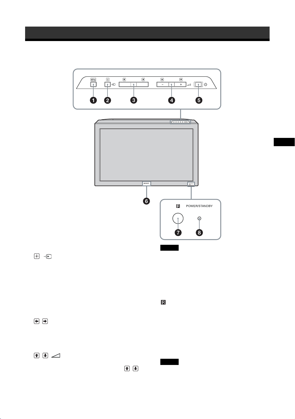
各部の名称と働き
前面パネル
JP
1 MENU(24 ページ)
2 /(INPUT)
・ メニュー画面で、「決定」ボタンとして使いま
す。
・ メニュー画面以外では、入力信号を切り換え
ます。
HD15/HDMI1/HDMI2/OPTION1/OPTION
2 端子からの入力信号を選びます。
OPTION1/OPTION2 スロットにオプション
アダプターがないときは、OPTION1/
OPTION2 をスキップします。
3 /
・ メニュー画面で、左右の移動ボタンとして使
います。
・ 2 画面モードでメニュー画面以外のときは、ア
クティブ画面や画面サイズを切り換えます。
4 //
・(+)と(−)で音量を調整します。
・ メニュー画面で、上下の移動ボタン( / )
として使います。
5 1
本機の電源を入/切(スタンバイ)します。
ご注意
パネル保護のため、電源の入/切(スタンバイ)
に時間がかかります。再度、電源を入れる場合
は約 5 秒待ってから行ってください。
6 ソニーロゴ
ソニーロゴが点灯します。
メニュー画面で「入」/「切」の切換ができま
す。34 ページの「詳細設定」をご覧ください。
7 リモコンセンサー
8 POWER/STANDBY(電源/スタンバイ)
インジケーター
・ 本機の電源を入れると緑色に点灯します。
・ 本機がスタンバイ状態のとき、赤色に点灯し
ます。
・ 現在の入力がビデオまたは S ビデオではない
とき、パワーセービングモードに入るとオレ
ンジ色に点灯します。
ご注意
「マルチディスプレイ設定」の「LED」が「切」
で、「ポジション設定」が右下以外の場合は、
ディスプレイの電源が入っていてもインジケー
ターは緑点灯しません(無信号時/未対応信号
時を除く)。
11
JP
Page 12
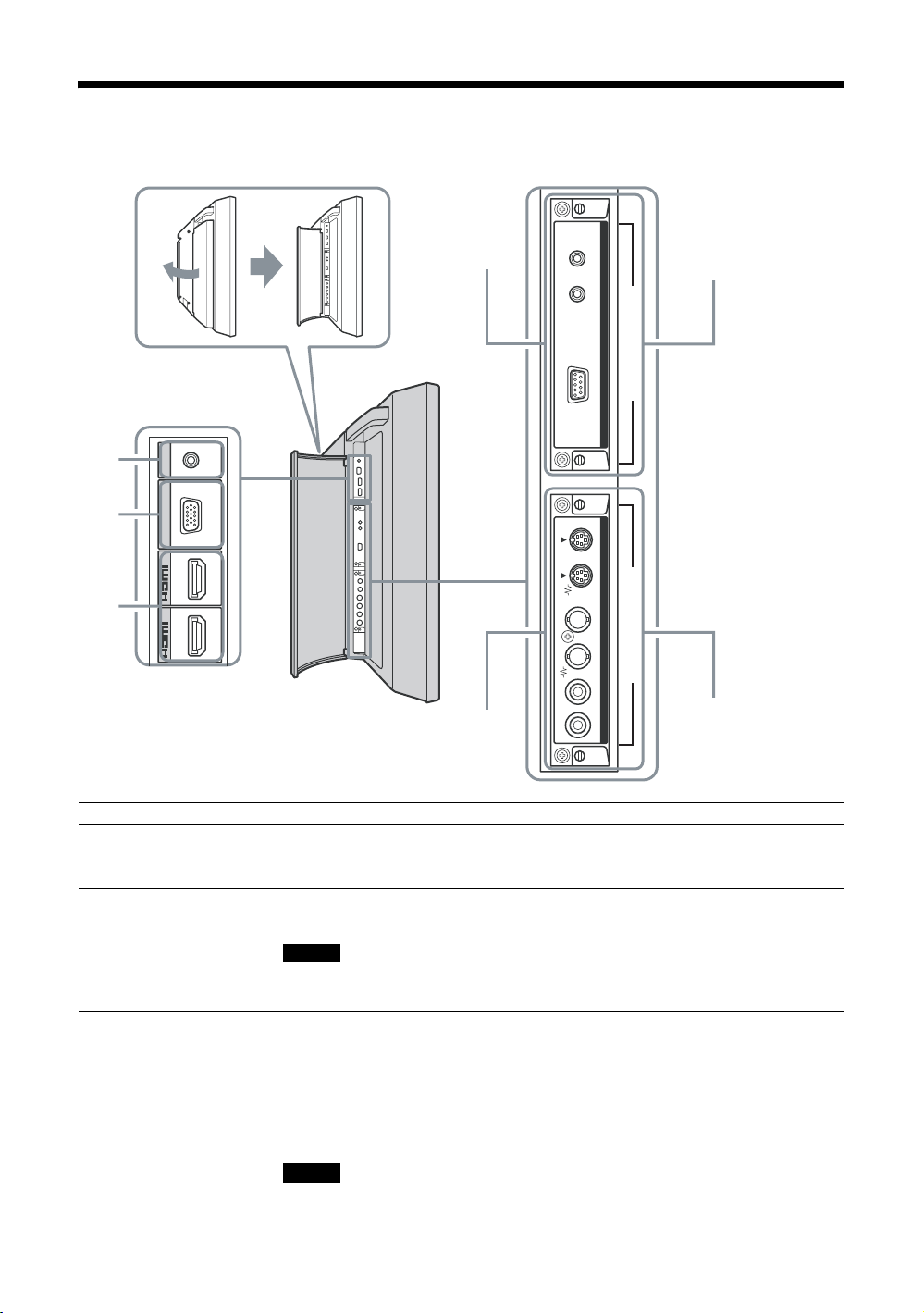
サイドパネル
ケーブルカバー(側面)を開けるには
1
2
3
AUDIO
HD 15
1
2
COM MON
AUDIO IN
RGB/COMPONENT IN
IN
IN
4
6
5 OPTION1スロット
(VIDEO/COM)
OUT IN
MONITOR CONTROL ADAPTOR
OPTION 1(VIDEO/COM)OPTION 2(VIDEO)
INOUTINOUTRL
S VIDEO REMOTE CONTROL S
VIDEO
VIDEO INPUT ADAPTOR
AUDIO IN
7
(VIDEO)
OPTION2 スロット
端子 説明
1AUDIO(COMMON
AUDIOIN)(ステレオミ
音声信号を入力します。映像機器や PC の音声出力端子と接続します。2 と 3
の音声入力に対応しています。
ニジャック)
2HD15(RGB/
COMPONENTIN)
(D-sub15 ピン)
映像機器や PC のアナログ RGB 信号出力端子、またはコンポーネント信号出力
端子と接続します。40 ページをご覧ください。
ご注意
コンポーネント信号を入力する際は 13,14 ピンに同期信号を入力しないでくだ
さい。画像が正しく表示されない場合があります。
3HDMI1/HDMI2IN HDMI(High-DefinitionMultimediaInterface)端子は本機と HDMI対応の音声
/映像機器や PC とのインターフェースを提供します。高精細な映像と 2チャ
ンネルのデジタル音声をお楽しみいただけます。
また、DVI対応機器を HDMI-DVIケーブル(市販品)で接続することもできま
す。
接続された機器によって、音声/映像機器または PC の適切なモードが自動選択
されます。
ご注意
HDMI ケーブル(別売)は、必ず HDMI ロゴの付いたケーブルをご使用くださ
い。
JP
12
Page 13

端子 説明
4MONITORCONTROL
ADAPTOR(モニターコ
ントロールアダプター)
(BKM-FW20 プリインス
トール)
5OPTION1 スロット
(VIDEO/COM ポート)
6VIDEOINPUT
ADAPTOR(ビデオ入力
アダプター)
(BKM-FW10 プリインス
トール)
7OPTION2 スロット
(VIDEOポート)
CONTROLSIN/OUT(ミニジャック):ディスプレイを含む他機器の
CONTROLS 端子に接続すると、1 台のリモコンで複数の機器を操作できます。
本機の CONTROLSOUT 端子とほかの機器の CONTROLSIN 端子、本機の
CONTROLSIN 端子とほかの機器の CONTROLSOUT 端子を接続します。
REMOTE(D-sub9 ピン):RS-232C プロトコルを使って本機を遠隔操作すると
きに使います。詳しくはお買い上げ店またはソニーのサービス窓口にご相談く
ださい。
このアダプターは OPTION2スロットでは動作いたしません。
映像信号および通信機能に対応したスロットです。オプションアダプター
(BKM-FWシリーズなど)を装着すると、入力信号端子を拡張したり、ネット
ワーク経由でディスプレイ制御を行うことが可能となります。
SVIDEOIN(ミニ DIN4 ピン):映像機器の S ビデオ信号出力端子と接続しま
す。
SVIDEOOUT(ミニ DIN4 ピン):映像機器の S ビデオ信号入力端子と接続し
ます。
VIDEOIN(BNC 型):映像機器のビデオ信号出力端子と接続します。
VIDEOOUT(BNC 型):映像機器のビデオ信号入力端子と接続します。
AUDIOINL/R(ピンジャック):映像機器の音声出力端子と接続します。
ビデオ信号もしくは Sビデオ信号は自動選択されます。ビデオ端子か Sビデオ
端子のどちらかに、ケーブル(別売)を接続してください。
接続した映像機器が Sビデオ出力端子を装備している場合、Sビデオ端子に接
続いただくと、より高画質をお楽しみいただけます。
映像信号に対応したスロットです。このスロットには、ビデオ信号入出力系の
オプションアダプターを装着することができます。通信機能のあるオプション
アダプターは、5 の OPTION1 スロットに取り付けてください。
ご注意
JP
13
JP
Page 14
オプションアダプ
ター
サイドパネル 5、7 の端子部はスロットイン方
式になっていて、以下のオプションアダプター
(別売)に付け換えることができます。
各アダプターの取り付けかたについては、お買
い上げ店またはソニーのサービス窓口にご相談
ください。
ビデオ入力アダプター BKM-FW10
OPTION2 スロット 7 にプリインストールさ
れているアダプターと同じものです。12 ページ
をご覧ください。
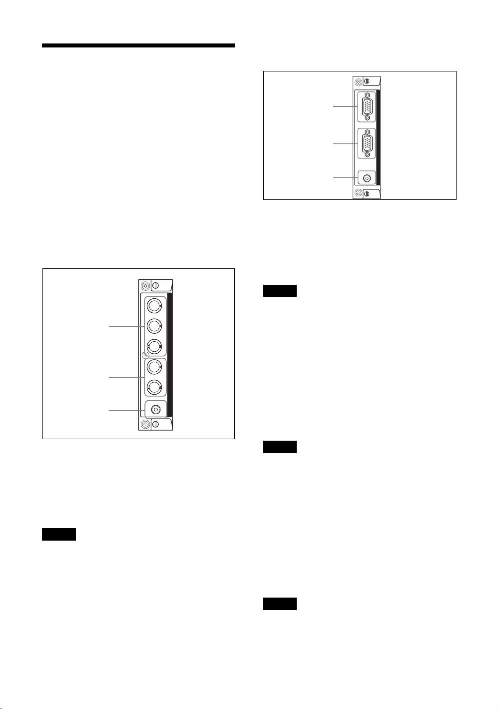
コンポーネント /RGB 入力アダプター
BKM-FW11
1
R/CR/R PB/CB/B Y/G
2
3
1 Y/GPB/CB/BPR/CR/R映像入力端子
(BNC 型):映像機器や PC のコンポーネン
ト信号出力端子またはアナログ RGB 信号出
力端子と接続します。
2 HDVD同期信号入力端子(BNC 型):PC
の同期信号出力端子と接続します。
ご注意
コンポーネント信号を入力する際は HD,VD に同期信
号を入力しないでください。画像が正しく表示されな
い場合があります。
3 AUDIO(音声入力)端子(ステレオミニ
ジャック):音声信号を入力します。映像機
器や PC の音声出力端子と接続します。
JP
14
VD HD P
COMPONENT/RGB INPUT ADAPTOR
AUDIO
RGB/ コンポーネントアクティブス
ルーアダプターBKM-FW12
1
2
3
AUDIO
OUT IN
IN
RGB/COMPONENT ACTIVE THROUGH
1 RGB/COMPONENTIN(RGB/ コンポー
ネント信号入力)端子(D-sub15 ピン):
映像機器や PC のアナログ RGB 信号出力端子
またはコンポーネント信号出力端子と接続し
ます。コンポーネント信号をこの端子へ入力
する場合には、40 ページのピン配列を参考に
してください。
ご注意
コンポーネント信号を入力する際は 13、14 ピンに同
期信号を入力しないでください。画像が正しく表示さ
れない場合があります。
2 RGB/COMPONENTOUT(RGB/ コンポー
ネント信号出力)端子(D-sub15 ピン):
映像機器や PC のアナログ RGB 信号入力端
子またはコンポーネント信号入力端子と接
続します。
3 AUDIOIN(音声入力)端子(ステレオミ
ニジャック):
音声信号を入力します。映像機器や PC の音
声出力端子と接続します。
ご注意
本機がスタンバイ状態のときや AC 電源が接続されて
いないときは、RGB/COMPONENTOUT 端子からは
出力されません。
ネットワークマネージメントアダプ
ター BKM-FW32
詳しくは BKM-FW32 の取扱説明書をご覧くだ
さい。
ストリーミングレシーバーアダプター
BKM-FW50
詳しくは BKM-FW50 の取扱説明書をご覧くだ
さい。
ご注意
BKM-FW32/50 にてネットワークケーブルを使用する
際は、不要電波の放射を抑えるため、シールドタイプ
のケーブルをお使いください。
また接続方法に関してはそれぞれの取扱説明書をご覧
ください。
その他、機能拡張用オプションアダプター
BKM-FW シリーズについては、それぞれの取
扱説明書をご覧ください。
Page 15
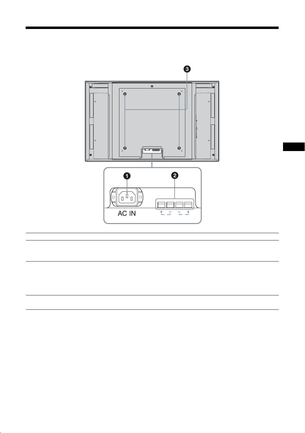
後面パネル
R
SPEAKER
JP
L
各部 説明
1ACIN(電源入力)ソ
ケット
2SPEAKER(スピー
カー)端子
3スタンド取り付け用
フック
付属の電源コードをこのソケットとコンセントに接続します。電源コードを接
続すると、POWER/STANDBY インジケーターが赤色に点灯し、本機はスタン
バイ状態になります。21 ページをご覧ください。
スピーカー SS-SP40FW/32FW(別売)をこの端子に接続すると、画面に表示さ
れている信号の音声を出力し、より臨場感あふれる映像をお楽しみいただけま
す。スピーカーの接続について詳しくは、スピーカーに付属の取扱説明書をご
覧の上、正しく接続してください。
また、スピーカーコードのまとめ方は、23 ページをご覧ください。
ディスプレイスタンドSU-42FW/32FW(別売)を取り付けるときに使用しま
す。
15
JP
Page 16
HDMI2
ON
STANDBY
HD15
ID MODE
OFF
SET
OPTION1
DISPLAY
ECO
SOUND
PICTURE
OPTION2
HDMI1
RM-FW001
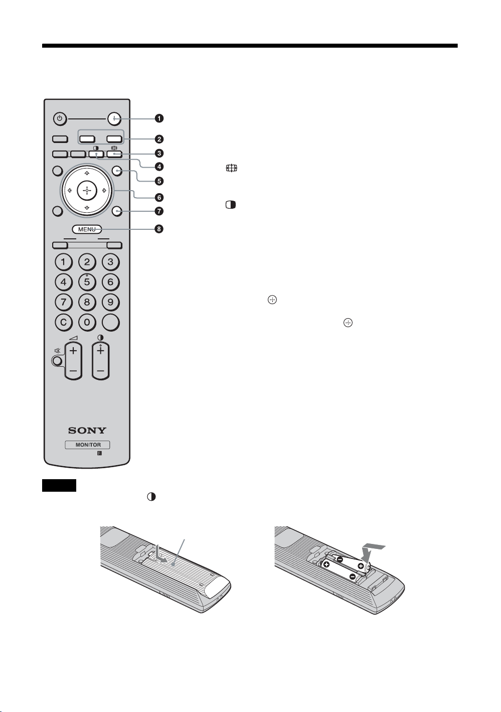
リモコン
ボタンの機能
STANDBY
HD15
HDMI1
OPTION1
OPTION2
DISPLAY
ECO
ONONID MODE
RM-FW001
ON
HDMI2
PICTURE
OFF
SET
SOUND
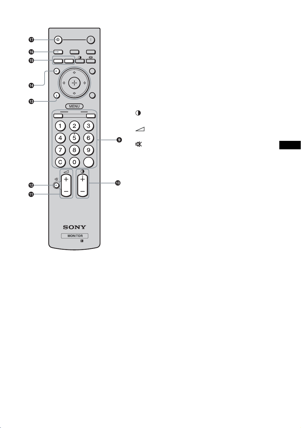
1 POWER(電源)ON スイッチ
押すと電源が入ります。
2 HDMI1/HDMI2 ボタン
HDMI1/HDMI2 端子に接続した機器からの入力信号を選び
ます。
3 ボタン
「ワイド切換」で画面のアスペクト比を変更します。18 ペー
ジをご覧ください
4 ボタン
「2 画面」モードを切り換えます。ボタンを押すごとに、2 画
面、1画面の順に切り替わります。19 ページをご覧くださ
い。
5 PICTURE ボタン
「画質モード」を切り換えます。ボタンを押すごとに、「ダイ
ナミック」、「スタンダード」、「カスタム」、「TCControl」の
順に切り替わります。
6 F/f/G/g/ ボタン
F/f/G/g
ボタンでメニューのカーソル(黄色)を移動させ
たり、数値などを設定します。 ボタンを押すと、選んだ
メニューや設定した内容を確定します。
2 画面モードでは、
G/gボタンでアクティブな画面を切り換
えることができます。
7 SOUNDボタン
「音質モード」を選びます。ボタンを押すごとに、「ダイナ
ミック」、「スタンダード」、「SRSWOW」、「カスタム」の順
に切り替わります。
8 MENU ボタン
画面にメニューを出すときに使用します。もう一度押すとメ
ニューが消えます。24 ページをご覧ください。
ご注意
・ 数字ボタンの「5」および ボタンには、凸部(突起)が付いています。操作の目印としてお使いください。
・ 付属の単 3 形乾電池 2 本を、リモコンの電池挿入部内部の図を確認しながら、3 極と # 極を正しく入れてくだ
さい。
押してスライドさせて開ける
16
JP
,
Page 17
HDMI2
ON
STANDBY
HD15
ID MODE
OFF
SET
OPTION1
DISPLAY
ECO
SOUND
PICTURE
OPTION2
HDMI1
RM-FW001
STANDBY
HD15
OPTION1
OPTION2
DISPLAY
ECO
ONONID MODE
HDMI1
RM-FW001
HDMI2
PICTURE
OFF
SET
ON
SOUND
9 IDMODE(ON/0-9/SET/C/OFF)ボタン
複数のディスプレイを使用しているとき、「インデックス番
号」を指定して、特定のディスプレイのみを操作することが
できます。
・ ON ボタン:「インデックス番号」を画面上に表示します。
・ 0-9 ボタン:操作したいディスプレイの「インデックス番
号」を入力します。
・ SET ボタン:入力した「インデックス番号」を設定しま
す。
・ C ボタン:入力した「インデックス番号」をクリアしま
す。
・ OFF ボタン:通常の画面に戻ります。
20 ページをご覧ください。
0 +/–ボタン
画像のコントラストを調整します。
qa +/–ボタン
音量を調整します。
qs ボタン
音を消します。もう一度押すと、音が出ます。
qd ECO ボタン
バックライトの明るさを調節して電力消費を抑え、黒レべル
が強調されます。「切」、「低」、「高」、「消画」から選びます。
20 ページをご覧ください。
qf DISPLAY ボタン
現在選択されている入力、入力されている信号の種類および
「ワイド切換」設定を画面に表示します。もう一度押すと表
示は消えます。表示された状態でしばらくたつと自動的に表
示は消えます。
qg OPTION1/OPTION2 ボタン
オプションアダプターを装着した際、そこに接続した機器か
らの入力信号を選びます。OPTION1 端子からの信号入力を
選ぶには OPTION1 ボタンを押し、OPTION2 端子からの信
号入力を選ぶには OPTION2 ボタンを押します。
qh HD15 ボタン
HD15 端子に接続した機器からの入力信号を選びます。接続
した機器によって RGB 信号またはコンポーネント信号が自
動選択されます。
qj STANDBY ボタン
押すとスタンバイ状態になります。
JP
17
JP
Page 18
リモコンの特別ボタン
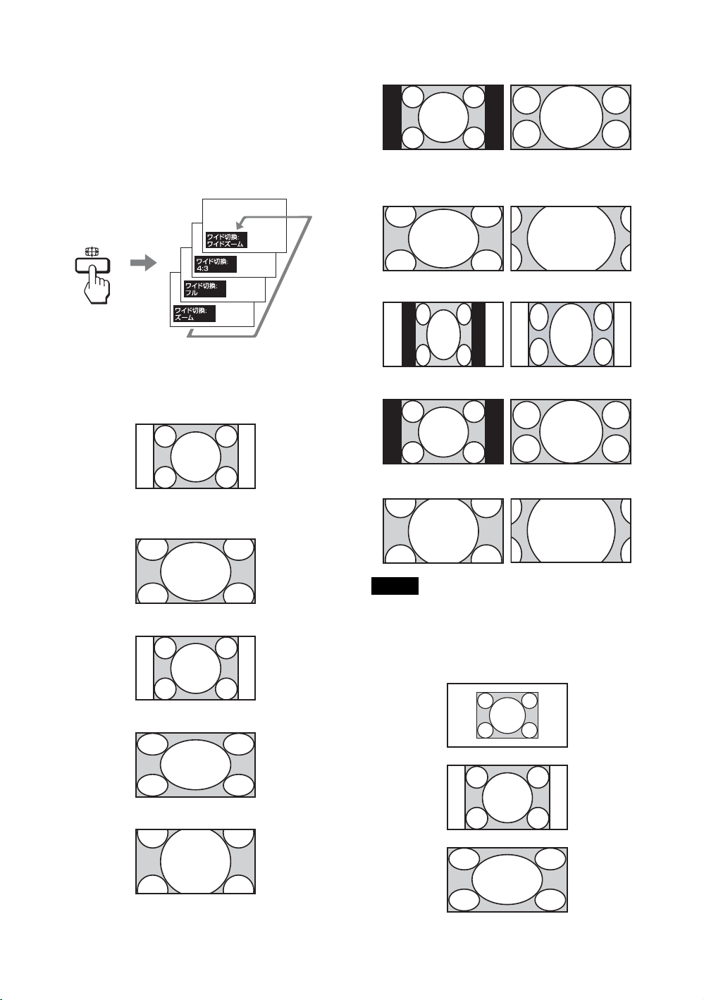
ワイド切換を使う
画面のアスペクト比を変更することができます。
ちょっと一言
「画面調整」メニューからも「ワイド切換」を設定す
ることができます。29、32 ページをご覧ください。
ビデオ、DVD、HDMI 入力の場合(PC 入力以
外)
4:3 の映像ソース
16:9 の映像ソース
m
ワイドズーム
4:3
フル
ワイド
ズーム
4:3
フル
ズーム
ズーム
m
ご注意
入力信号が 1080i、720p、1080p のときは、「ワイド
ズーム」および「4:3」は選択できません。29 ページ
をご覧ください。
PC 入力の場合
ノーマル
フル 1
フル 2
18
JP
Page 19
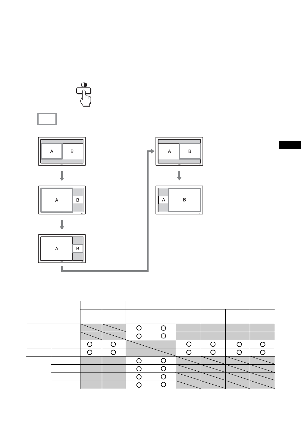
2 画面設定を使う
PC とビデオなど、ふたつの異なる信号の映像
を、並べて表示します。また左右画面の入れ換
えや、画面の大きさのバランスも自由に変えら
れます。
ちょっと一言
「画面調整」メニューからも「2 画面設定」を設定す
ることができます。30 ページをご覧ください。
アクティブな画面を示すカーソル
A と B の横幅は同
じになります。
高さは各画像のアス
ペクト比によって決
まります。
Gボタンを押す
A の横幅は B の横幅
より大きくなりま
す。
A のアスペクト比が
4:3 なら、A の高さ
はパネルのサイズと
等しくなります。
g
ボタンを押す
右側の B がアクティ
ブな画像となりま
す。
g
ボタンを押す
利用可能な 2 画面の組み合わせ
HD15 HDMI1 HDMI2 OPTION1&2
RGB コンポー
HD15 RGB
コンポーネント
HDMI1 HDMI/DVI
HDMI2 HDMI/DVI
OPTION
1&2
RGB
コンポーネント
ビデオ
S ビデオ
ネント
HDMI/
DVI
HDMI/
DVI
A と B の横幅は同じにな
ります。
高さは各画像のアスペク
ト比によって決まります。
gボタンを押す
B の横幅は A の横幅より大
きくなります。
B のアスペクト比が 4:3
なら、B の高さはパネルの
サイズと等しくなります。
RGB コンポー
ネント
JP
ビデオ S ビデオ
19
JP
Page 20
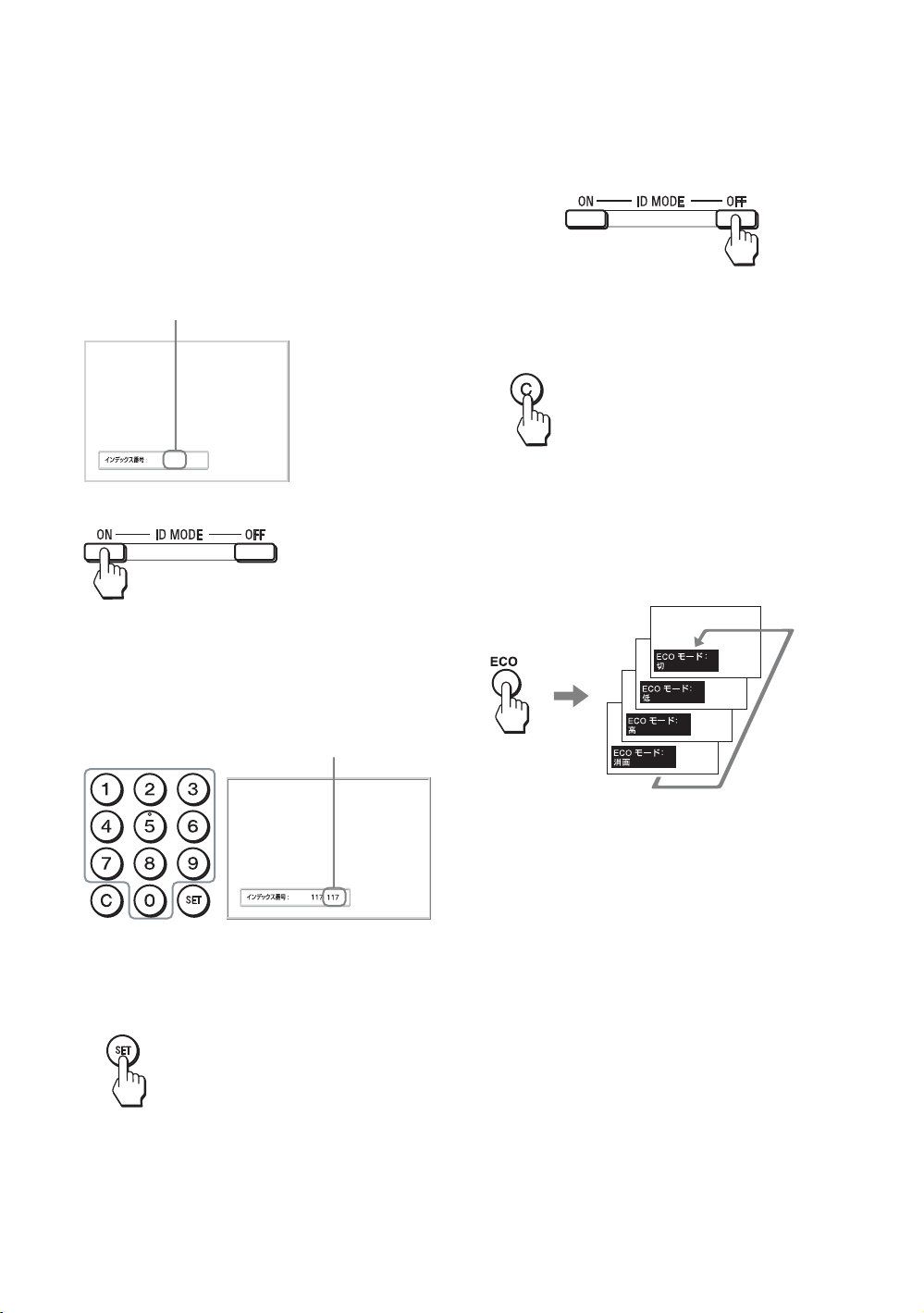
IDMODE ボタンを使う
複数のディスプレイを使用しているとき、「イ
ンデックス番号」を指定して、特定のディスプ
レイのみを操作することができます。
1 ON ボタンを押す。
「インデックス番号」が、画面左下のメ
ニューに黒い文字で表示されます(「イン
デックス番号」は、1 から 255 の範囲で、あ
らかじめ各ディスプレイに設定されていま
す)。
インデックス番号
4 設定変更等の操作が終了したら、OFF ボ
タンを押す。
ディスプレイは通常の画面に戻ります。
インデックス番号を訂正するには
C ボタンを押して、現在入力されている「イン
デックス番号」を消去します。手順 2 に戻り、
新しい「インデックス番号」を入力します。
117
2 リモコンの 0 から 9 のボタンで、操作した
いディスプレイの「インデックス番号」
を入力する。
すべてのディスプレイの「インデックス番
号」の右に、入力した数字が表示されます。
入力された番号
3 SET ボタンを押す。
選択したディスプレイの文字が緑色に変わ
り、その他のディスプレイの文字は赤色に
変わります。
ちょっと一言
ディスプレイの「インデックス番号」を変更するに
は、34 ページの「コントロール設定」の「リモート
インデックス」をご覧ください。
ECO モード機能を使う
本機の消費電力を減らすことができます。
ECO モードを解除するには
「ECO モード:切」が表示されるまで、ECO ボ
タンを繰り返し押します。
ちょっと一言
・「ECO モード」を有効にしたまま本機の電源を切る
と、次回に本機の電源を入れたときも設定された
モードが保持されます(「消画」の場合を除く)。
・「設定」メニューからも「ECO モード」を設定する
ことができます。「設定」メニューから「ECO モー
ド」を選び、「切」、「低」、「高」、「消画」のいずれ
かに設定してください。
これで特定のディスプレイ(文字が緑色に
変わったディスプレイ)のみを操作できま
す(POWER(電源)ON スイッチ、
STANDBY ボタン、および IDMODE-OFF
ボタンの操作だけは、ほかのディスプレイ
にも有効です)。
JP
20
Page 21
接続
接続上のご注意
・ 各機器の電源を切ってから接続を行ってください。
・ 接続ケーブルはそれぞれの端子の形状に合った正し
いものをお選びください。
・ 接続ケーブルは端子にしっかり差し込んでくださ
い。接続が悪いとノイズの原因となります。
・ ケーブルを抜くときは必ずプラグを持って抜いてく
ださい。決してケーブルそのものを引っ張らないで
ください。
・ 接続の詳細については、各機器の取扱説明書をご覧
ください。
・ 電源コードのプラグは、ACIN ソケットに、まっ
すぐ突き当たるまで差し込んでください。
・ 付属の AC プラグホルダーは、使用する電源コード
のプラグが確実に固定できる方を選んでお使いくだ
さい。
スピーカーの接続
スピーカー SS-SP40FW/32FW(別売)を接続
して、より臨場感あふれる映像をお楽しみいた
だけます。スピーカーの接続について詳しく
は、スピーカーに付属の取扱説明書をご覧の
上、正しく接続してください。また、スピー
カーコードのまとめ方は、23 ページをご覧くだ
さい。
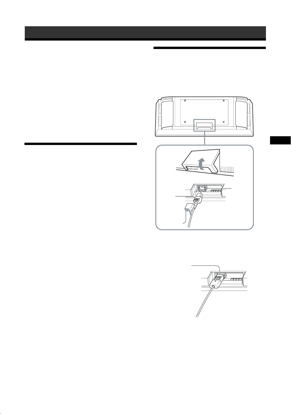
電源コードの接続
1 電源コードを底部の ACIN ソケットに差
し込み、AC プラグホルダー(付属)を電
源コードに取り付ける。
JP
ACIN
ソケット電源
コード
AC プラグ
ホルダー
2 AC プラグホルダーをスライドさせて、本
体側の ACIN ソケットカバーにはめ込
む。
ACIN ソケット
カバー
電源コードをはずすには
AC プラグホルダーのつめをはさみ、ロックを
解除してからプラグをつかみ、電源コードをは
ずしてください。
21
JP
Page 22
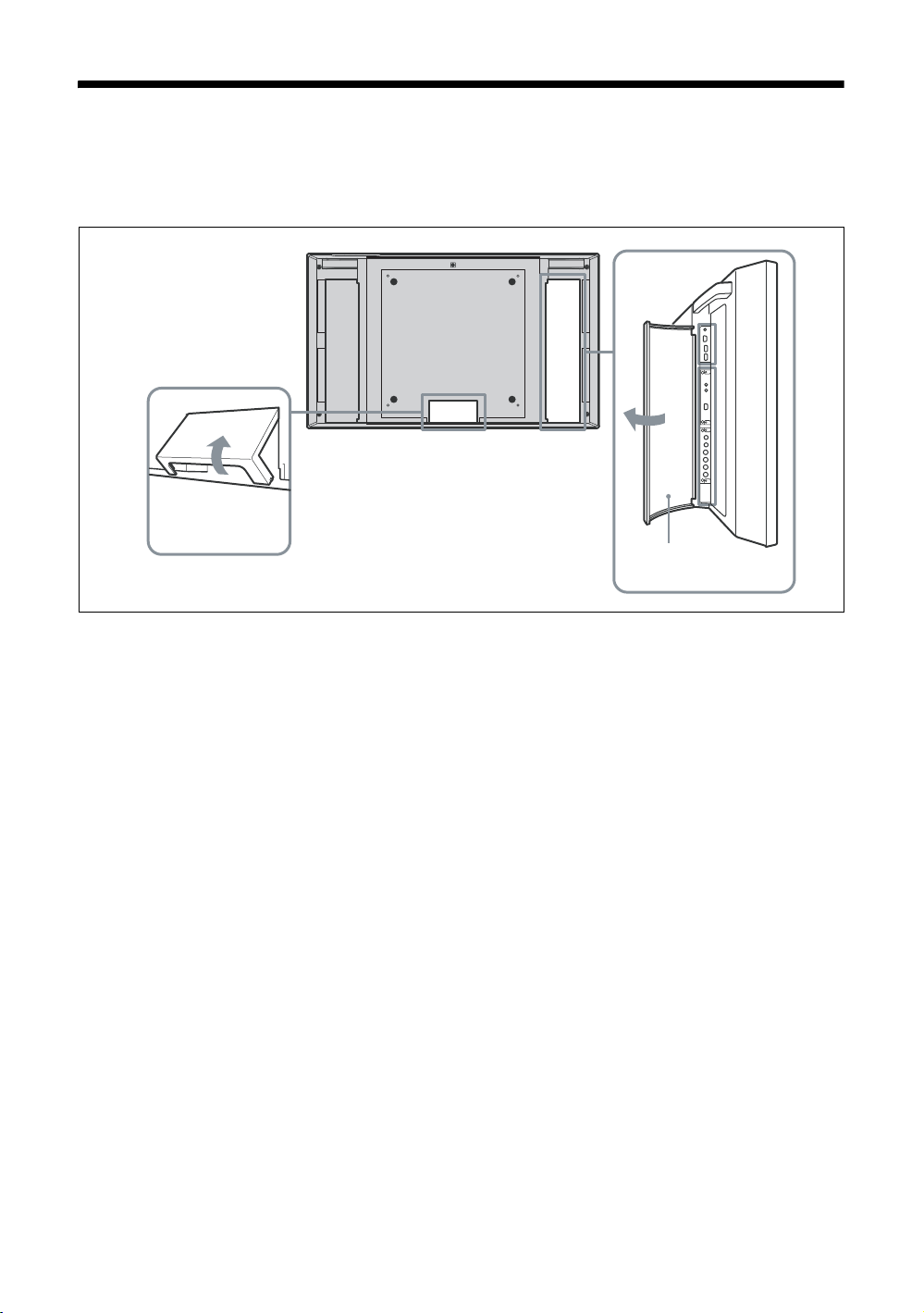
ケーブルを処理する
本機には、背面をすっきり見せるためにケーブルカバーが取り付けてあります。ケーブル類を接続す
る前に、以下に示すようにケーブルカバーを開けてください。すべてのケーブルを取り付けた後に、
ケーブルカバーを閉めてください。
ケーブルカバー
(底部)
ケーブルカバー
(側面)
22
JP
Page 23
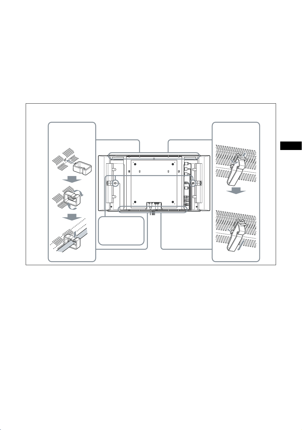
ケーブルホルダーを使う
付属のケーブルホルダーを使って、ケーブル類をすっきりまとめることができます。ケーブルホル
ダーは、以下のように取り付けます。
FWD-40LX2F/40LX2X
ケーブルホルダー(4 個付属)を上部と底部のスリットに 2 個ずつ取り付けます。尚、スピーカー(別
売)を接続したときは、スピーカーコードをディスプレイ後面のスピーカーコード用ホルダーに通し
てください。
FWD-32LX2F/32LX2X
ケーブルホルダー(6 個付属)を取り付け用の穴の 8 か所(上部に 4 か所、底部に 4 か所)のうち、任
意の 6 か所を使って取り付けます。尚、スピーカーコード用ホルダーは付属しません。
FWD-32LX2F/32LX2X
ケーブルホルダー
本体取り付け穴に
挿入後、90 度回
転
スピーカーコード
用ホルダー
(FWD-40LX2F/
40LX2X のみ)
後面
FWD-40LX2F/40LX2X
ケーブルホルダー
ヒンジ部を押して
ロック爪を開く
JP
ホルダーをスリッ
トに挿し込む
23
JP
Page 24
メニューの設定
メニュー一覧
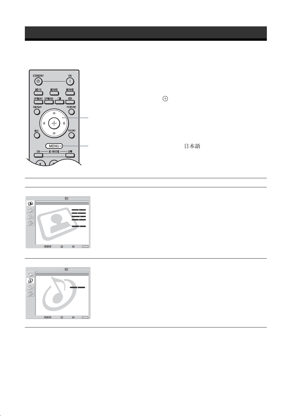
1 MENU ボタンを押す。
2 F/fボタンで設定したいメニューのアイ
3 ボタンまたはg ボタンを押す。
2,3
メニュー表示の言語を変更する
メニュー表示とメッセージの言語を、
「English」、「Español」、「Français」、「Italiano」、
1
メニュー画面から以下の項目を設定することができます。
メニュー画面 設定/変更できる項目
画質
画質
画質モード:ダイナミック
画質モード標準
コントラスト: 50
明るさ: 40
色の濃さ: 60
色あい: 0
色温度:高
シャー プネ ス: 18
NR: 入
シネモーション:
True Color Control
決定:
選択
:
音質
音質
音質モード:ダイナミック
音質モード標準
高音:
低音:
バランス:中心
音声入力選択: HD 15
スピーカー出力:入
自動
戻る
:
HDMI 1
終了
HDMI 1
MENU
:
画質モード(26、27 ページ)
画質モード標準(26、27 ページ )
コントラスト(26、27 ページ )
明るさ(26、27 ページ )
色の濃さ(26 ページ )
色あい(26 ページ )
色温度(26、27 ページ )
シャープネス(26 ページ )
NR(26 ページ )
シネモーション (26 ページ )
TrueColorControl(26 ページ )
音質モード(28 ページ )
音質モード標準(28 ページ )
高音(28 ページ )
低音(28 ページ )
バランス(28 ページ )
音声入力選択(28 ページ )
スピーカー出力(28 ページ )
「Deutsch」、「 」から選びます。
初期設定では「English」(英語)に設定されて
います。
33 ページをご覧ください。
コンを選ぶ。
メニューの操作を終了するには、MENU ボ
タンを押します。
24
JP
選択
:
戻る
終了
MENU
:
:
決定:
Page 25
メニュー画面 設定/変更できる項目
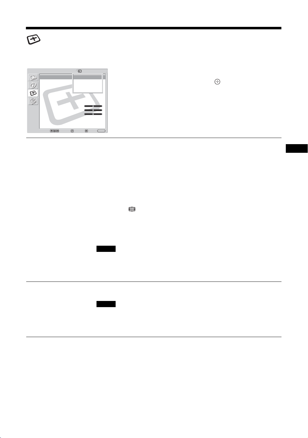
画面調整
画面調整
ワイド切換: ワイドズーム
オートワイド:入
4:3映像: ワイドズーム
表示エリア:ノーマル
自動調整
画位相:
ドットピッチ:
水平位置: 0
垂直位置: 0
垂直サイズ:
標準
2 画面設定
マルチディスプレイ設定
決定:
選択
:
HDMI 1
0
MENU
:
:
終了
戻る
ワイド切換(29、32 ページ )
オートワイド(29 ページ )
4:3映像(30 ページ )
表示エリア(30 ページ )
自動調整(32 ページ )
画位相(32 ページ )
ドットピッチ(32 ページ )
水平位置(30、32 ページ )
垂直位置(30、32 ページ )
垂直サイズ(30 ページ )
標準(30、32 ページ )
2 画面設定(30 ページ )
マルチディスプレイ設定(31 ページ )
設定
設定
言語: ᣣᧄ⺆
タイマー設定
ECO モード:
オートシャットオフ:
詳細設定
インフォメーション
オールリセット
IP Address Setup
Speed Setup
HDMI 1
切
切
言語(33 ページ )
タイマー設定(33 ページ )
ECO モード(33 ページ )
オートシャットオフ(33 ページ )
詳細設定(34 ページ )
インフォメーション(34 ページ )
オールリセット(34 ページ )
IPAddressSetup(35 ページ )
選択
:
戻る
終了
MENU
:
:
決定:
SpeedSetup(35 ページ )
* メニュー画面の下の行に表示されているアイコンは、設定項目によっては、働かないことがあります。
JP
25
JP
Page 26
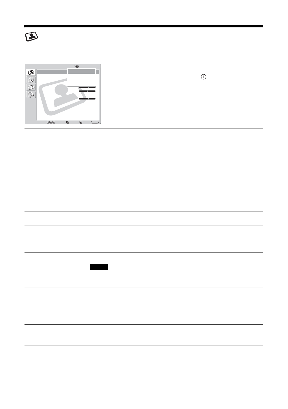
画質メニュー
ビデオ入力の場合
画質
画質モード: Vivid
画質モード標準
コントラスト: Max
明るさ: 40
色の濃さ: 60
色あい: 0
色温度:高
シャー プネ ス: 18
NR :
シネモーション:自動
True Color Control
ダイナミック
スタンダード
カスタム
TC Control
入
HDMI 1
項目を選んで設定を変えるには、F/f/G/g ボ
タンを押します。
設定を確定するには ボタンを押します。
「画質」メニューには、以下の項目が含まれま
す。
: :
選択
決定
:
画質モード
画質モード標準
コントラスト
明るさ
色の濃さ
色あい
MENU
:
終了
戻る
「ダイナミック」:映像の輪郭を強調しコントラストを最大限に上げます。
「スタンダード」:標準的な設定です。
「カスタム」:お好みに合わせて細かく調整します。
「TCControl」:設定は「ダイナミック」と共通です。加えて「TrueColor
Control」機能(後述)が使用可能となります。
ちょっと一言
・ リモコンの PICTURE ボタンでも「画質モード」の設定を切り換えることができま
す。
・ 各入力ごとに「画質モード」を設定することができます。
現在選択中の「画質モード」(「ダイナミック」、「スタンダード」、「カスタ
ム
」、「TCControl」)について、すべての設定や調整値を初期設定に戻し
ます(グレイアウトしている項目を除く)。
コントラストの強弱を調整します。
映像の明るさを調整します。
色の濃淡を調整します。
映像の色調を調整します。
ご注意
入力信号がビデオまたは S ビデオで、映像信号のカラー方式が NTSC でない場合、
「色あい」は調整できません。
色温度
シャープネス
NR
(ノイズリダクション)
シネモーション
JP
26
「高」:青みがかった白色になります。
「中」:中間の白色になります。
「低」:赤みがかった白色になります。
映像の輪郭の強弱を調整します。
接続した機器からのノイズを軽減します。「入」または「切」を選んでく
ださい。
「自動」を選ぶと、映画の映像素材を検知し、リバース 3-2 プルダウンまた
はリバース 2-2 プルダウン処理によって画面表示を自動的に最適化します。
動画がより鮮明かつ自然に見えます。「切」を選ぶと、この検知を行いま
せん。
Page 27
TrueColor
Control
ちょっと一言
それぞれの「画質モード」ごとに、「画質」メニュー(「コントラスト」、「明るさ」、「色の濃さ」など)を設定する
ことができます。
ご注意
・ 2 画面モード時、画質メニューの項目はすべて選択不可能となります。
・ 現在の入力が無信号の場合、「画質」メニューの項目はすべて選択不可能となります。
赤、緑、黄、青の4色それぞれについて色合いと鮮やかさを調整すること
で、画像の中の特定の色を強調したりすることができます。
調整したい色を選択すると、現在の画像でどの部分が調整されようとして
いるのかを視認した後、ダイアログボックス上のマトリクスでその色を調
整することができます。
ご注意
・ この項目は「画質モード」が「TCControl」の場合に調整することがで
きます。
・ 2 画面モード時は、この設定を行うことはできません。たとえ 1 画面時
に設定しても、2 画面モード時には反映されない場合があります。
PC 入力の場合
入力を PC 入力に切り換えた場合、PC 用の「画
質」メニューとなります。
PC 用の「画質」メニューには、以下の項目が
含まれます。
JP
画質モード
画質モード標準
コントラスト
明るさ
色温度
TrueColor
「ダイナミック」:映像の輪郭とコントラストを最大限に上げます。
「スタンダード」:標準的な設定です。
「カスタム」:お好みに合わせて細かく調整します。
「TCControl」:設定は「ダイナミック」と共通です。加えて「TrueColor
Control」機能(後述)が使用可能となります。
現在選択中の「画質モード」(「ダイナミック」、「スタンダード」、「カスタ
ム」、「TCControl」)について、すべての設定や調整値を初期設定に戻し
ます(グレイアウトしている項目を除く)。
コントラストの強弱を調整します。
映像の明るさを調整します。
ビデオ入力時の「色温度」をご覧ください(26 ページ)。
ビデオ入力時の「TrueColorControl」をご覧ください(27 ページ)。
Control
ご注意
・「色の濃さ」、「色あい」、「シャープネス」、「NR」、「シネモーション」は、PC 入力時は調整できません。
・ 2 画面モード時、「画質」メニューの項目はすべて選択不可能となります。
・ 現在の入力が無信号の場合、「画質」メニューの項目はすべて選択不可能となります。
27
JP
Page 28
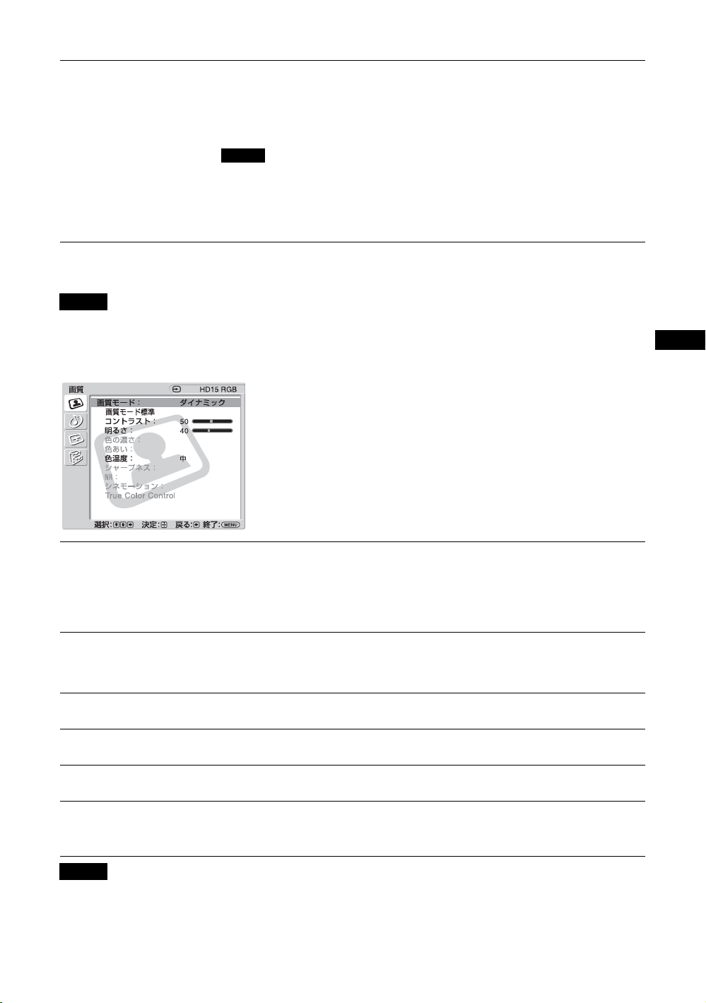
音質メニュー
音質
音質モード: Dynamic
音質モード標準
高音:
低音:
バランス:中心
音声入力選択: HD15
スピーカー出力:入
: :
選択
決定
ダイナミック
スタンダード
SRS WOW
カスタム
:
音質モード
音質モード標準
高音
低音
HDMI 1
スピーカー SS-SP40FW/32FW(別売)を接続
しているときは、各種「音質」メニューを設定
することができます。
項目を選んで設定を変えるには、
タンを押します。
設定を確定するには ボタンを押します。
「音質」メニューには、以下の項目が含まれま
す。
MENU
:
終了
戻る
「ダイナミック」:高音と低音を強調します。
「スタンダード」:標準的な設定です。
「SRSWOW」:ふくよかな重低音とクリアな高音によって、立体感のある
ステレオ音声を提供します。映画館のような迫力のある音響を楽しむこと
ができます。
「カスタム」:お好みに合わせて細かく調整します。
ちょっと一言
・ リモコンの SOUND ボタンでも「音質モード」の設定を切り換えることができま
す。
・「ダイナミック」と「スタンダード」に BBE の技術が使用されています。
「高音」、「低音」、「バランス」の設定を初期設定に戻します。
高音の強弱を調整します。
低音の強弱を調整します。
F/f/G/g ボ
バランス
音声入力選択
スピーカーの左右出力バランスを調整します。
「HD15」:HD15(RGB/COMPONENTIN)端子と AUDIO(COMMON
AUDIOIN)端子に接続された映像機器や PC からの音声を出力します。
「HDMI1」/「HDMI2」:HDMIケーブル(別売)またはHDMI-DVI
ケーブルを接続し、さらに別途、対応するオーディオケーブルを同時に接
続する場合に選択します。
12 ページをご覧ください。
ご注意
・ HDMI-DVI ケーブル(市販品)をご使用の場合は、オーディオケーブルを
AUDIO(COMMONAUDIOIN)端子に接続してください。
・「HDMI1」または「HDMI2」を選択すると HDMI 端子からのデジタル音声が出
力されません。HDMI 端子搭載の映像機器を HDMI1/HDMI2端子に接続すると
、「HD15」に設定してください(デフォルトは「HD15」に設定されていま
きは
す)。
スピーカー出力
「入」:スピーカーから音声を出力します。
「切」:スピーカーから音声を出力しません。
ご注意
「スピーカー出力」が「切」のときは、「音質モード」、「音質モード標準」、「高音」、
「低音」、「バランス」は選択できません。
ちょっと一言
「音質モード」で「カスタム」を選択しているときは、「音質」メニュー(「高音」、「低音」)を設定することができ
ます。
JP
28
Page 29
画面調整メニュー
ビデオ入力の場合
画面調整
ワイド切換: Wide Zoom
オートワイド: On
4:3 映像: Wide Zoom
表示エリア: No
自動調整
画位相:
ドットピッチ:
水平位置: 0
垂直位置: 0
垂直サイズ:
標準
2画面設定
マルチディスプレイ設定
: :
選択
決定
:
HDMI 1
ワイドズーム
4:3
フル
ズーム
0
:
終了
戻る
MENU
項目を選んで設定を変えるには、F/f/G/g ボ
タンを押します。
設定を確定するには ボタンを押します。
「画面調整」メニューには、以下の項目が含ま
れます。
ワイド切換
オートワイド
「ワイドズーム」:ゆがみを最低限に抑えて映像を拡大し、画面いっぱいに
表示します。
「4:3」:4:3 の映像ソース(標準画質)を、そのままのアスペクト比で表示
します。
「フル」:4:3 の映像ソース(標準画質)を水平方向に拡大し、画面いっぱ
いに表示します。16:9 の映像ソース(高画質)の場合は、そのままのアス
ペクト比で表示します。
「ズーム」:アスペクト比を保ったまま、映像を拡大します。
18 ページをご覧ください。
ちょっと一言
・ リモコンの ボタンでも「ワイド切換」の設定を切り換えることができます。
・ 映画などの DVD 映像で、黒帯のある映像を画面いっぱいに映して楽しみたいと
きは、「ズーム」を選んでください。
・「ワイドズーム」または「ズーム」が選ばれているときは、映像の「水平位置」
「垂直位置」「垂直サイズ」を調整することができます。30 ページをご覧くださ
い。
ご注意
・「2 画面」機能または「マルチディスプレイ」使用時は、「ワイド切換」はできま
せん。
・ コンポーネント端子または HDMI 端子に入力された 1080i、720p、1080p の信号
に対しては、「ワイドズーム」と「4:3」は選択できません。
「入」:映像を検知して、自動的に適切な画面設定に変更します。
「切」:画面設定を自動で変更しません。
ご注意
・ 入力信号がデジタルおよびアナログ RGB のときは、「オートワイド」は働かない
ので使用できません。
・「2 画面」機能または「マルチディスプレイ」を使用時は、「オートワイド」は設
定できません。
JP
29
JP
Page 30
4:3映像
「ワイドズーム」:4:3 の映像ソースを、元のイメージを可能な限り保った
まま、16:9 に拡大します。
「4:3」:4:3 の映像ソースをそのままのアスペクト比で表示します。
「フル」:4:3 の映像ソースを水平方向にのみ拡大し、16:9 にします。
「ズーム」:4:3 の映像ソースをアスペクト比を保ったまま、画面全体に映
るように拡大します。レターボックス方式の映画を見るのに適していま
す。
「切」:入力信号が切り替わっても、現在のワイド設定を保ちます。
ご注意
・「4:3 映像」は、「オートワイド」が「入」のときにのみ選択可能です。
・「4:3映像」は、入力信号が NTSC、PAL、SECAM、480i、480p、575i、または
576p のときにのみ、働きます。
・「4:3 映像」を設定したあとで「ワイド切換」の設定を変更すると、その設定が有
効になり、アスペクト比が変わります。この「ワイド切換」による後からの設定
変更は入力信号ごとに有効なため、入力信号切換時には、元の「4:3 映像」の設定
に戻ります。入力信号を切り換えても現在のアスペクト比のままにするには「4:3
映像」を「切」に設定してください。
表示エリア
水平位置
垂直位置
垂直サイズ
標準
2 画面設定
「ノーマル」:標準サイズの映像を表示します。
「− 1」/「− 2」:映像の見える領域を調整します。画面の外側にノイズ
が見える場合に選択すると、ノイズを隠すことができます。
映像の左右の位置を調整します。「ワイドズーム」または「ズーム」が選
ばれているときにのみ、調整できます。G/gボタンと ボタンで調整結
果を確定します。
映像の上下の位置を調整します。「ワイドズーム」または「ズーム」が選
ばれているときにのみ、調整できます。F/f ボタンと ボタンで調整結
果を確定します。
映像の垂直サイズを調整します。「ワイドズーム」または「ズーム」が選
ばれているときにのみ、調整できます。F/fボタンと ボタンで調整結
果を確定します。
「水平位置」、「垂直位置」、「垂直サイズ」の設定を初期設定に戻します。
PC とビデオなど、ふたつの異なる信号の映像を、並べて表示します。
デジタル信号とアナログ信号の組み合わせのみご利用になれます。
「2 画面」:「入」を選ぶと、ふたつの映像を同時に並べて表示します。「切」
を選ぶと、「2 画面」機能を解除します。
「画面入替」:「実行」を選ぶと、ふたつの映像を入れ換えます。「取消」を
選ぶと、入れ換えを取り消します。
「画面サイズ」:
「左大」:左画面の横幅を、右画面よりも大きくします。左画面のアス
ペクト比が 4:3 の場合、縦幅はディスプレイのサイズと同じになりま
す。
「同サイズ」:左右の画面の横幅を同じにします。縦幅は、それぞれの
映像のアスペクト比に合ったものになります。
「右大」:右画面の横幅を、左画面よりも大きくします。右画面のアス
ペクト比が 4:3 の場合、縦幅はディスプレイのサイズと同じになりま
す。
ご注意
・「マルチディスプレイ」が「切」のときにのみ、2 画面表示をすることができま
す。
・ 2 画面表示をしているときは、両画面ともに 1 画面時の「画質」設定が適用され
ます。
・ 2 画面表示できる信号の組み合わせについて詳しくは、19 ページをご覧くださ
い。
30
JP
Page 31

マルチディスプレ
イ設定
本機を複数台接続して、ビデオウォールを構成するための設定をします。
「マルチディスプレイ」:「切」を選ぶと、1 画面表示になります。「2 × 2」
〜「4 × 4」を選ぶと、それぞれの構成のビデオウォールになります。
「ポジション設定」(配置ポップアップ):個々のディスプレイの画面位置
を、
F/f/G/g ボタンで選びます。 ボタンで位置を確定します。
「出画形式」:図にある 2 種類の映像出力形式から選びます。いずれかの形
式を選択することにより、水平・垂直位置を手動で調整しなくても、最適
な映像出力が得られます。「タイル」または「ウィンドウ」を選んでくだ
さい。
「タイル」
ジャストスキャン
「ウインドウ」
オーバースキャン
JP
それぞれの画面に、映像信号を
完全に表示します。
ひとつの大きな映像を、複数の画面
で自然に表示します。
映像信号の一部は、ベゼルの後ろに
隠れます。
「LED」:「入」を選ぶと、本機前面の POWER/STANDBY インジケー
ター(11 ページ)が点灯しつづけます。「切」を選ぶと、消灯します。
ご注意
・「マルチディスプレイ」は、ビデオ入力の場合は現在の「ワイド切換」を極力維
持した映像を、PC 入力の場合は「ワイド切換」の「フル 2」の映像を表示するこ
とができます。
・「2 画面」機能を使用していないときにのみ、「マルチディスプレイ設定」を設定
することができます。
・「ポジション設定」を右下に設定すると、「LED」を「切」にしても、POWER/
STANDBY インジケーターが緑色に点灯します。インジケーターは、無信号時/
未対応信号時も含め、ディスプレイがオフ(スタンバイ)時、異常検出時、ス
リープ状態時にも点灯します。
ご注意
・「表示エリア」、「水平位置」、「垂直位置」、「垂直サイズ」は、「2 画面」機能や「マルチディスプレイ設定」の使
用中は設定できません。
・ 現在の入力が無信号の場合、「画面調整」メニューの項目は「2 画面設定」と「マルチディスプレイ設定」を除い
て、すべて選択不可能となります。
31
JP
Page 32

PC 入力の場合
画面調整
ワイド切換:ノーマル
オートワイド:
4:3映像:
表示エリア:
自動調整
画位相: 0
ドットピッチ: 0
水平位置: 0
垂直位置: 0
垂直サイズ:
標準
2 画面設定
マルチディスプレイ設定
: :
選択
決定
HD15 RGB
入力を PC 入力に切り換えた場合、PC 用の「画
面調整」メニューとなります。
PC 用の「画面調整」メニューには、以下の項
目が含まれます。
:
戻る
MENU
:
終了
ワイド切換
自動調整
画位相
ドットピッチ
水平位置
垂直位置
標準
「ノーマル」:映像を元のままのサイズで表示します。
「フル 1」:アスペクト比を保ったまま、映像を画面垂直方向いっぱいに拡
大します。映像の周囲に黒い帯が出ることがあります。
「フル 2」:映像を画面いっぱいに拡大します。
ご注意
「2 画面」機能または「マルチディスプレイ設定」使用時は、「ワイド切換」はでき
ません。
接続した PC からの入力信号を受けたとき、自動的に映像の位置や位相を
調整します。
入力信号の種類によっては、「自動調整」がうまく働かないことがありま
す。その場合は、下記の項目を手動で調整してください。
画面がちらちらしているとき、位相を調整します。
映像におかしな縞模様が出るとき、ピッチを調整します。
映像の左右の位置を調整します。G/g ボタンと ボタンで調整結果を確
定します。
映像の上下の位置を調整します。F/fボタンと ボタンで調整結果を確
定します。
「画位相」、「ドットピッチ」、「水平位置」、「垂直位置」の設定を初期設定
に戻します。
2 画面設定
マルチディスプレ
ビデオ入力時の「2 画面設定」をご覧ください(30 ページ)。
ビデオ入力時の「マルチディスプレイ設定」をご覧ください(31 ページ)。
イ設定
ご注意
・「オートワイド」、「4:3映像」、「表示エリア」、「垂直サイズ」は、PC 入力時は設定できません。
・ 現在の入力が無信号の場合、画面調整メニューの項目は「2 画面設定」と「マルチディスプレイ設定」を除いて、
すべて選択不可能となります。
・ 現在の入力が HDMI1/HDMI2の場合、「自動調整」、「画位相」、「ドットピッチ」は PC 入力時は設定できませ
ん。
JP
32
Page 33

設定メニュー
設定
言語:
タイマー設定
ECO モード:
オートシャットオフ:
詳細設定
インフォメーション
オールリセット
IPAddressSetup
SpeedSetup
選択
::
決定
言語
タイマー設定
ECO モード
HDMI 1
English
English
Español
Français
Off
Italiano
Off
Deutsch
:
戻る
MENU
:
終了
項目を選んで設定を変えるには、F/f/G/g ボ
タンを押します。
設定を確定するには ボタンを押します。
「設定」メニューには、以下の項目が含まれま
す。
メニュー表示の言語を、「English」、「Español」、「Français」、「Italiano」、
「Deutsch」、「 」のなかから選びます。
時刻合わせ、内蔵時計の表示、およびあらかじめ決めた時間に自動で電源
JP
を入/切するタイマー機能の設定をすることができます。
「時刻設定」:日時を設定します。
「時計表示」:「入」を選ぶと、設定された現在時刻を表示します。
「電源タイマー」:自動的に電源を入/切する時間を設定します。
ご注意
時刻が大幅にずれたりするときは、内蔵電池の消耗が考えられます。お買
い上げ店またはソニーのサービス窓口に電池の交換をご依頼ください(有
料)。
「切」:省電力機能を使用しません。
「低」/「高」:消費電力を減らします。黒レベルが強調されます。
「消画」:映像を消します。音声はそのままの音量で流れます。
オートシャットオ
フ
「入」:ビデオ入力、S ビデオ入力に無信号の状態が約5分続くと、本機は
自動的にスタンバイ状態になります。また HDMI入力、RGB/ コンポーネ
ント入力に無信号の状態が約 30 秒続くと、自動的にパワーセービング状
態になります。
「切」:各入力に無信号の状態が続いても、本機の電源は切れません。
ちょっと一言
スタンバイ状態のときは 1POWER(パワー)スイッチまたはリモコンの
POWERON スイッチを押すと、電源が入ります。またパワーセービング
状態のときは、信号が入力されると自動的に電源が入ります。
33
JP
Page 34

詳細設定
「カラー方式」:「NTSC」、「PAL」、「SECAM」、「NTSC4.43」、「PAL-M」、
「PAL-N」、「PAL60」から映像信号のカラー方式を設定します。「自動」を
選ぶと、カラー方式が自動的に設定されます。
「ステータス表示」:「入」を選ぶと、電源を入れたときに入力信号と「ワ
イド切換」の情報が、画面に約 20 秒間表示されます。また、入力信号を
切り換えると、入力信号の情報が約 5 秒間表示されます。「切」を選ぶと、
情報は表示されません。
ちょっと一言
リモコンの DISPLAY ボタンで、「ステータス表示」の設定にかかわらず入力信号と
「ワイド切換」の情報を表示させることができます。
「イルミネーション」:「入」を選ぶと、本機前面の Sony ロゴが点灯しま
す。「切」を選ぶと、消灯します。
「コントロール設定」:本機およびリモコンの操作に関する設定を行いま
す。
「リモートインデックス」:必要に応じて、本機の「インデックス番号」
を変更します。
F/fボタンで「インデックス番号」を設定し、ボタ
ンで決定します。
ご注意
「インデックス番号」を設定するときは、本機のボタンをご使用ください。リモ
コンでは設定できません。
「コントロールモード」
「本体+リモコン」:本機のボタンおよびリモコンで、本機を操作で
きます。
「本体のみ」:リモコンでの操作を無効にします。本機のボタンでの
み、本機の設定をすることができます。
「リモコンのみ」:リモコンだけで操作したいときに、本機の操作を
無効にします。リモコンでのみ、本機の設定をすることができま
す。
「切」:リモコンおよび本機のボタンのどちらの操作も無効にしま
す。本機の REMOTE 端子(BKM-FW20)および通信機能を持つ
オプションアダプター(BKM-FW32/FW50 など)経由で本機を操
作できます。
ご注意
・ この項目を設定するとき、使用するボタンによって選べるモードが異なりま
す。リモコンの ボタンで設定するときは、「本体+リモコン」か「リモコ
ンのみ」を選べます。本機の ボタンで設定するときは、「本体+リモコ
ン」か「本体のみ」を選べます。
・「切」に設定すると、リモコンおよび本機のボタンでの操作ができなくなりま
すが、本機の MENUボタンと + ボタンを 5 秒以上同時に押すことで、
「本体+リモコン」の設定に戻すことができます。
インフォメーショ
ン
オールリセット
JP
34
「機種名」、「シリアル番号」、「累積通電時間」、「ソフトウェアバージョ
ン」、および「IPAddress」を表示します
ご注意
通信機能を持つオプションアダプターがインストールされていないと、「IP
Address」は表示されません。
すべての「設定」メニューを初期設定に戻します。
ご注意
「インフォメーション」に含まれる内容と、「インデックス番号」はリセットされませ
ん。
Page 35

IPAddress
Setup
本機に装着した通信機能を持つオプションアダプター(BKM-FW32/
FW50 など)と、LAN ケーブルで接続された PC などの機器とが通信でき
るように IP アドレスを設定します。
「DHCP」:「OK」を選ぶと、自動的に IP アドレスを設定します。「Cancel」
を選ぶと、自動設定を中止します。
ご注意
DHCP で IP アドレスを自動取得したときは、電源の入/切をすると、IP アドレス
が変わることがあります。
「Manual」:IP アドレスを手動で設定します。
1 「IPAddress」、「SubnetMask」、「DefaultGateway」、「Primary
DNS」、「SecondaryDNS」を
2 本機の
(0 〜 255)を入力し、 ボタンまたは
3 4 つの枠にそれぞれ 3 桁の値(0 〜 255)を入力し、 ボタンを押す。
4
5 設定したいすべての項目に値を入力したら、F/f ボタンで「Execute」
「OK」を選んで、 ボタンを押すと、IP アドレスが手動で設定されます。
ご注意
IP アドレスが正しく設定されていないと、原因に応じて、次のようなエラーコード
が表示されます。
Error1:本機と BKM-FW32、BKM-FW50 などの間の通信エラー
Error2:IPアドレスがほかで使われている
Error3:IPアドレスの設定不備
Error4:Gatewayaddress の設定不備
Error5:PrimaryDNS の設定不備
Error6:SecondaryDNS の設定不備
Error7:Subnetmask の設定不備
F/fボタンまたはリモコンの数字ボタンで、最初の枠に3 桁の値
F/f ボタンで次に設定したい項目を選び、同じ手順をくり返し、 ボ
タンを押す。
を選び、 ボタンを押す。
F/f ボタンで選び、 ボタンを押す。
g ボタンを押す。
JP
SpeedSetup
ご注意
通信機能を持つオプションアダプターがインストールされていないと、「IPAddressSetup」と「SpeedSetup」は
設定できません。
本機に装着した通信機能を持つオプションアダプター(BKM-FW32/
FW50 など)と、LAN ケーブルで接続された PC などの機器との間の通信
速度を設定します。
「Speed」:「Auto」を選ぶと、ネットワーク構成に適切な通信速度が自動
的に設定されます。また、「10MbpsHalf」、「10MbpsFull」、「100Mbps
Half」、「100MbpsFull」のいずれかの通信速度を選ぶこともできます。
「Execute」:「OK」を選んで、 ボタンを押すと、通信速度が設定されま
す。
35
JP
Page 36

その他の情報
故障かな?と思ったら
POWER/STANDBY インジケーターが赤く点滅していないか確認する。
点滅している場合
自己診断機能が働いています。
1 POWER/STANDBY インジケーターの点滅回数および消灯時間をはかる。
たとえば、2 回点滅→ 3 秒消灯→2 回点滅となります。
2 本機(上部)の 1(電源)を押して電源を切り、電源コードを抜く。
お買い上げ店またはソニーサービス窓口にインジケーターの点滅状態(点滅回数および消灯時間)
をお知らせください。
点滅していない場合
1 以下の表の項目を点検する。
2 それでも正常に動作しないときは、お買い上げ店またはソニーサービス窓口に修理を依頼する。
こんなときは 原因と対処のしかた
本機の電源スイッチおよびコントロー
ルボタンが働かない。
画像が出ない。
画像が出ない。
本機の電源が自動的に切れる。
特定の入力からの画像が出な
い。
画像が見にくい。
色がつかない/画像が暗い/画
像が明るすぎる/色がおかしい
音が出ない/音にノイズが混じる。
画像はきれいだが、音声が出な
い。
「ワイド切換」の設定が自動的に変わ
る。
・「コントロール設定」を確認してください(34 ページ)。
・「ECO モード」の設定を確認してください(33 ページ)。
・「タイマー設定」が有効になっていないか確認してください
(33 ページ)。
・ 映像機器と本機の接続を確認してください。
・ 本機の INPUT ボタンまたはリモコンで入力を切り換えてみて
ください(11、16、17 ページ)。
・ PICTURE ボタンを押してご希望の「画質モード」に切り換え
てください(16 ページ)。
・「画質」メニューで「画質モード」の項目を調整してください
(26 ページ)。
・ 接続ケーブルの状態を点検してください。
・ 音量を確認してください。
・ リモコンの または +を押して「消音」を画面から消し
てください(17 ページ)。
・「音声入力選択」の設定を確認してください(28 ページ)。
・「スピーカー出力」の設定を確認してください(28 ページ)。
・「画面調整」メニューの「オートワイド」が「入」に設定され
ているとき、入力を切り換えると、現在の「ワイド切換」設
定は、自動的に入力信号に合わせた設定に変わります。入力
を切り換えても現在の「ワイド切換」設定を保ちたいときは、
「画面調整」メニューの「オートワイド」を「切」に設定して
ください(29 ページ)。
36
JP
Page 37

こんなときは 原因と対処のしかた
リモコンが動かない。
・ 電池の+/−が正しく挿入されているか確認してください。
もしくは電池を交換してください。
・ リモコンを本機のリモコンセンサーに向けてください。
・ リモコンセンサーのまわりに障害物を置かないようにしてく
ださい。
・「コントロール設定」を確認してください(34 ページ)。
・ CONTROLSIN 端子にケーブルが接続されていないか確認し
てください。本機が CONTROLS 接続によって制御されてい
るとき、リモコンはご使用になれません。
・ 蛍光灯によってリモコンの操作に障害が出る場合があります。
蛍光灯を消してみてください。
JP
37
JP
Page 38

入力信号一覧表
PC 信号
解像度
VGAa)-1(VGA350) 31.5 70
1
2
640ー480@60Hz
b)
(VESA
3
Macc)13" 35.0 67
4
VGA(VGATEXT) 31.5 70
5
800×600@60Hz
(VESASTD)
6
Mac16" 49.7 75
7
1024×768@60Hz
(VESASTD)
8
1024×768@75Hz
(VESASTD)
9
1024×768@85Hz
(VESASTD)
10
1280×1024@60Hz
(VESASTD)
11
848×480@60Hz
(VESASTD)
12
848×480@60Hz
(VESASTD)
13
848×480@75Hz 37.7 75
14
1280×768@60Hz 47.8 60
15
1280×768@60Hz 47.4 60
16
1360×768@60Hz 47.7 60
17
1360×768@60Hz 47.4 60
STD)
水平周波数
(kHz)
31.5 60
37.9 60
48.4 60
60.0 75
68.7 85
64.0 60
29.8 60
29.5 60
TV/ ビデオ信号
利用可能な入力
解像度
1480/60i
2 480/60p
3575/50i aaa
4 576/50p
5 720/50p
6 720/60p
7 1080/50i
8 1080/60i
9 1080/50p
10 1080/60p
ビデオ コンポー
a
垂直周波
数(Hz)
HDMI
ネント /
RGB
aa
aa
aa
aa
aa
aa
aa
a
a
a) VGA は米国 InternationalBusinessMachines
Corporation の登録商標です。
b) VESA は VideoElectronicsStandardsAssociation
の登録商標です。
c)Mac(Macintosh)は AppleComputer,Inc. の登録
商標です。
ご注意
・ HDTV信号を入力する場合、同期信号は 3 値同期信
号を HD15 端子または BKM-FW12(オプションア
ダプター)の RGB/COMPONENT 端子(D-sub15
ピンコネクター)の 2番ピンに入力してください。
・ 本機で DVD 信号を入力した場合、画像の色を薄く
感じたら、「画質」メニューの「色の濃さ」でお好
みの色の濃さに調整してください。
・ 位相を再調整すると解像度が低下します。
入力信号/ディスプレイ設定情報の画
面表示
画面表示 意味
640×480/60
(例)
480/60I(例) コンポーネント信号が入力さ
NTSC(例) NTSC 信号が入力されていま
標準信号ではあり
ません。
信号がありません。 入力信号がありません。
HD15 HD15 入力が選択されてい
HDMI1 HDMI1 入力が選択されてい
HDMI2 HDMI2 入力が選択されてい
Option1 OPTION1 入力が選択され
Option2 OPTION2 入力が選択され
PC 信号が入力されています。
れています。
す。
標準信号でない信号が入力さ
れています。
ます。
ます。
ます。
ています。
ています。
38
JP
Page 39

仕様
映像処理系
パネル方式 a-SiTFTActiveMatrixLCDPanel
解像度 1,366 ドット(水平)× 768 ライン
(垂直)
サンプリング周波数
13.5MHz〜140MHz
カラー方式 NTSC,PAL,SECAM,NTSC4.43,
PAL60,PAL-M,PAL-N
入力信号 38 ページをご覧ください。
FWD-40LX2F/40LX2X:
ピクセルピッチ 0.648(水平)× 0.648(垂直)mm
有効表示寸法 885(水平)× 498(垂直)mm
画面サイズ 40(V)型(対角 1,016mm)
FWD-32LX2F/32LX2X:
ピクセルピッチ 0.510(水平)× 0.510(垂直)mm
有効表示寸法 698(水平)× 392(垂直)mm
画面サイズ 32(V)型(対角 801mm)
入出力
HD15
(RGB/COMPONENTIN)
D-sub15 ピン(メス)(× 1)
40 ページをご覧ください。
AUDIO
(COMMONAUDIOIN)
ステレオミニジャック(× 1)
500mVrms、ハイインピー
ダンス
HDMI1/HDMI2IN HDMI(HDMI 規格1.1 準拠 )
ビデオ入力アダプター BKM-FW10
VIDEOIN BNC型(× 1)
コンポジットビデオ1Vp-p±2dB
同期負、75Ω 自動終端
VIDEOOUT BNC 型(× 1)ループスルー
SVIDEOIN ミニ DIN4 ピン(× 1)
Y(輝度):1Vp-p±2dB同期負、
75Ω 終端
C(クロマ):バースト0.286Vp-p±
2dB(NTSC)、75Ω 終端
バースト 0.3Vp-p±2dB
(PAL)、75Ω 終端
SVIDEOOUT ミニ DIN4 ピン(× 1)ループス
ルー
AUDIOIN ピンジャック(× 2)
500mVrms、ハイインピーダンス
モニターコントロールアダプター BKM-FW20
REMOTE(RS-232C) D-sub9 ピン(×1)
CONTROLSIN/OUT ミニジャック(×2)
その他
電源 AC
100V 〜 240V、50/60Hz、
FWD-40LX2F/40LX2X:2.3A
FWD-32LX2F/32LX2X:1.3A
消費電力
FWD-40LX2F/40LX2X:200W
FWD-32LX2F/32LX2X:120W
スピーカー出力 7W+7W(6Ω)
適合負荷インピーダンス
6 〜 16Ω
動作条件
温度:0 〜 35℃
湿度:20 〜 90%
(結露のないこと)
保存・輸送条件
温度:− 10 〜+ 40℃
湿度:20 〜90%
(結露のないこと)
外形寸法 FWD-40LX2F:
988×591×125mm
FWD-40LX2X:
994×597×125mm
FWD-32LX2F:
796×486×107mm
FWD-32LX2X:
802×492×107mm
(幅/高さ/奥行き、最大突起部含
まず)
質量 FWD-40LX2F:
約 25.0kg
FWD-40LX2X:
約 26.0kg
FWD-32LX2F:
約 16.0kg
FWD-32LX2X:
約 17.0kg
付属品
電源コード(1)
AC プラグホルダー(2)
ケーブルホルダー
40 インチ用(4)、32 インチ用(6)
コンポーネントビデオ信号ケーブル
(HD15-RCA × 3)(1)
BNC-RCA 変換アダプター(1)
変換プラグアダプター(1)
リモコン RM-FW001(1)
単 3 形乾電池(2)
取扱説明書(1)
保証書(ソニー業務用製品ご相談窓
口のご案内)(1)
別売アクセサリー
ディスプレイスタンドSU-42FW/
32FW
スピーカーSS-SP40FW/32FW
機能拡張用オプションアダプター
BKM-FW シリーズ
JP
本機の仕様および外観は、改良のため予告なく
変更することがありますが、ご了承ください。
39
JP
Page 40

WOW、SRS と( )記号は SRSLabs,Inc. の
商標です。
WOW 技術は SRSLabs,Inc. からのライセンス
に基づき製品化されています。
この製品はBBESound,Inc.からの実施権に基
づき製造されています。
この製品は米国BBESound,Inc.の所有する特
許 USP5510752 及び5736897 を使用していま
す。BBEとBBEのシンボルは、BBESound,
Inc. の登録商標です。
ピン配列
HD15(RGB/COMPONENT)端子(D-sub
15 ピン)
ピンNo. 信号
1 赤映像信号または CR/PR信号
2 緑映像信号または Y信号
3 青映像信号または C
4 接地(GND)
5 接地(GND)
6 赤接地(GND)
7 緑接地(GND)
8 青接地(GND)
9 未使用
10 接地(GND)
11 接地(GND)
12 SDA
13 水平同期信号またはコンポジット
ビデオ信号
14 垂直同期信号
15 SCL
B/PB
信号
40
ご注意
コンポーネント信号を入力する際は 13,14 ピンに同期
信号を入力しないでください。画像が正しく表示され
ない場合があります。
安全規格 電安法、VCCI クラス B
本機は「JISC61000-3-2適合品」で
す。
JISC61000-3-2適合品とは、日本工
業規格「電磁両立性 - 第 3-2部:
限度値-高調波電流発生限度値
(1 相当たりの入力電流が 20A 以
下の機器)」に基づき、商用電力
系統の高調波環境目標レベルに適
合して設計・製造した製品です。
JP
Page 41

索引
あ
明るさ24,26,27
イルミネーション34
色あい24,26
色温度24,26,27
色の濃さ24,26
インデックス番号17,20,34
インフォメーション25,34
ウィンドウ31
オートシャットオフ25,33
オートワイド25,29
オールリセット25,34
音質メニュー24,28
音質モード24,28
音質モード標準24,28
音声入力選択24,28
音量ボタン11,17
か
画位相25,32
画質メニュー24,26
画質モード24,26,27
画質モード標準24,26,27
カスタム26,27,28
画面入替30
画面サイズ30
画面調整メニュー25,29
カラー方式34
ケーブルカバー(側面)12,22
ケーブルカバー(底部)22
ケーブルホルダー23
言語25,33
高音24,28
コントラスト24,26,27
コントラストボタン17
コントロールモード34
コントロール設定34
さ
時刻設定33
自動調整25,32
シネモーション24,26
シャープネス24,26
出画形式31
消音ボタン17
詳細設定25,34
垂直位置25,30,32
垂直サイズ25,30
水平位置25,30,32
ズーム18,29
スタンダード26,27,28
スタンド取り付け用フック15
ステータス表示34
スピーカー出力24,28
設定メニュー25,33
ソニーロゴ11,34
た
ダイナミック26,27,28
タイマー設定25,33
タイル31
低音24,28
電源タイマー33
時計表示33
ドットピッチ25,32
な
入力信号38
ノーマル18,30,32
は
バランス24,28
ビデオ入力アダプター13,14
表示エリア25,30
標準25,30,32
フル18,29,30
フル1/フル218,32
ポジション設定31
ま
マルチディスプレイ設定25,31,
32
モニターコントロールアダプ
13
ター
ら
リモートインデックス34
リモコンセンサー11
わ
ワイド切換18,25,29,32
ワイド切換ボタン16,18
ワイドズーム18,29,30
数字
2画面設定19,25,30,32
2画面ボタン16,19
4:318,29,30
4:3映像25,30
A
ACINソケット15,21
AUDIO(COMMONAUDIOIN)
12
端子
AUDIOINL/R端子13
C
CONTROLSIN/OUT端子13
D
DHCP35
DISPLAYボタン17
E
ECOボタン17,20
ECOモード20,25,33
H
HD15ボタン17
HD15(RGB/COMPONENTIN)
12
端子
HDMI1/HDMI2IN端子12
HDMI1/HDMI2ボタン16
I
IDMODEボタン17,20
INPUTボタン11
IPAddressSetup25,35
L
LED31
M
Manual
(IPAddressSetup)
MENUボタン11,16
35
N
NR(ノイズリダクション)24,
26
O
OPTION1/OPTION2
スロット
OPTION1/OPTION2
ボタン
13,14
17
P
PICTUREボタン16
POWERスイッチ11
POWER/STANDBYインジケー
11
ター
POWER(電源)ON
スイッチ
16
R
REMOTE端子13
S
SVIDEOIN/OUT端子13
SOUNDボタン16
SPEAKER端子15
SpeedSetup25,35
SRSWOW28
STANDBYボタン17
T
TCControl26,27
TrueColorControl24,27
V
VIDEOIN/OUT端子13
41
JP
Page 42

WARNING
Owner’s Record
The model and serial numbers are located on the rear.
Record the model and serial numbers in the spaces
provided below. Refer to these numbers whenever you
call upon your Sony dealer regarding this product.
Model No.
To reduce the risk of fire or electric shock,
do not expose this apparatus to rain or
moisture.
Serial No.
is no guarantee that interference will not occur in a
particular installation. If this equipment does cause
harmful interference to radio or television reception,
which can be determined by turning the equipment off
and on, the user is encouraged to try to correct the
interference by one or more of the following
measures:
• Reorient or relocate the receiving antenna.
• Increase the separation between the equipment and
receiver.
• Connect the equipment into an outlet on a circuit different
from that to which the receiver is connected.
• Consult the dealer or an experienced radio/TV technician
for help.
You are cautioned that any changes or modifications
not expressly approved in this manual could void your
authority to operate this equipment.
To avoid electrical shock, do not open the
cabinet. Refer servicing to qualified
personnel only.
On transportation
When you carry the display unit, hold the unit itself,
not the speakers. If you fail to do so, the speakers may
come out of the unit and the unit may fall. This can
cause injury.
For customers in the U.S.A.
If you have any questions about this product, you may
call; Sony Customer Information Services Center
1-800-222-7669 or http://www.sony.com/
Declaration of Conformity
Trade Name: SONY
Model: FWD-40LX2F/FWD-
40LX2X/FWD-32LX2F/
FWD-32LX2X
Responsible Party: Sony Electronics Inc.
Address: 16530 Via Esprillo, San
Diego, CA 92127 U.S.A.
Telephone Number: 858-942-2230
This device complies with Part 15 of the FCC Rules.
Operation is subject to the following two conditions:
(1) This device may not cause harmful interference,
and (2) this device must accept any interference
received, including interference that may cause
undesired operation.
This equipment has been tested and found to comply
with the limits for a Class B digital device, pursuant to
Part 15 of the FCC Rules. These limits are designed to
provide reasonable protection against harmful
interference in a residential installation. This
equipment generates, uses, and can radiate radio
frequency energy and, if not installed and used in
accordance with the instructions, may cause harmful
interference to radio communications. However, there
For customers in Canada
This class B digital apparatus complies with Canadian
ICES-003.
Voor de klanten in Nederland
• Dit apparaat bevat een vast ingebouwde batterij die niet
vervangen hoeft te worden tijdens de levensduur van het
apparaat.
• Raadpleeg uw leverancier indien de batterij toch
vervangen moet worden. De batterij mag alle en vervangen
worden door vakbekwaam servicepersoneel.
• Gooi de batterij niet weg maar lever deze in als klein
chemisch afval (KCA).
• Lever het apparaat aan het einde van
de levensduur in voor recycling, de
batterij zal dan op correcte wijze
verwerkt worden.
The socket-outlet should be installed near the
equipment and be easily accessible.
CAUTION
RISK OF EXPLOSION IF BATTERY IS REPLACED
BY AN INCORRECT TYPE. DISPOSE OF USED
BATTERIES ACCORDING TO THE LOCAL RULES.
Trademark Information
WOW, SRS and ( ) symbol are trademarks of SRS
Labs, Inc. WOW technology is incorporated under
license from SRS Labs, Inc.
Manufactured under license from BBE Sound, Inc.
Licensed by BBE Sound, Inc. under one or more of the
following US patents: 5510752, 5736897. BBE and
BBE symbol are registered trademarks of BBE Sound,
Inc.
NL
GB
2
Page 43

Table of Contents
Introduction
Precautions ...............................................................................................................................4
Recommendations on Installation.............................................................................................6
Location and Function of Parts and Controls
Front Panel................................................................................................................................7
Side Panel.................................................................................................................................8
Optional Adaptors ...................................................................................................................10
Rear Panel ..............................................................................................................................11
Remote Control .......................................................................................................................12
Button Description..............................................................................................................12
Special Buttons on the Remote Control............................................................................. 14
Using the Wide Mode.................................................................................................... 14
Using the PAP Setting ..................................................................................................15
Using the ID MODE button ...........................................................................................16
Using the ECO Mode function ......................................................................................16
x
Connections
GB
Connecting the Speakers........................................................................................................17
Connecting the AC Power Cord..............................................................................................17
Cable Management.................................................................................................................18
Using the Settings
Overview of the Menus ...........................................................................................................20
Picture Settings .......................................................................................................................22
Sound Settings........................................................................................................................24
Screen Settings.......................................................................................................................25
Setup Settings.........................................................................................................................29
Other Information
Troubleshooting ......................................................................................................................32
Input Signal Reference Chart..................................................................................................33
Specifications ..........................................................................................................................34
Index .......................................................................................................................................36
GB
3
Page 44

Introduction
Precautions
On safety
• A nameplate indicating operating voltage, power
consumption, etc. is located on the rear of the unit.
• Should any solid object or liquid fall into the cabinet,
unplug the unit and have it checked by qualified personnel
before operating it any further.
• Unplug the unit from the wall outlet if it is not to be used
for several days or more.
• To disconnect the AC power cord, pull it out by grasping
the plug. Never pull the cord itself.
• When you install the unit on the floor, be sure to use the
optional display stand.
On installation
• Allow adequate air circulation to prevent internal heat
build-up. Do not place the unit on surfaces (rugs, blankets,
etc.) or near materials (curtains, draperies) that may block
the ventilation holes.
• Do not install the unit in a location near heat sources such
as radiators or air ducts, or in a place subject to direct
sunlight, excessive dust, mechanical vibration or shock.
• When you install multiple equipment with the unit, the
following problems, such as malfunction of the remote
control, noisy picture, noisy sound, may occur depending
on the position of the unit and other equipment.
On the LCD panel
• You may see some bright spots of red, blue or green, or
dark spots appearing on the screen. These do not indicate
a malfunction. Although the LCD panel is manufactured
with extremely high precision technology, it can generate
a few dark or bright pixels.
• Keeping the LCD panel facing toward the sun for a long
time will damage the panel. Take this into account when
you install the unit outdoor or by a window.
• Do not push, scratch or put a heavy weight on the panel.
These can cause irregularities in the screen or a
malfunction of the LCD panel.
• You may find the screen looks darker or an afterimage
occurs when using the unit in a colder environment. These
do not indicate a malfunction. The screen will return to
normal operation as the temperature rises.
• If you display a still image continuously, a ghosting may
occur. This symptom will be gradually resolved by
changing the image or making the whole screen display in
white. In addition, if you display the same still image for
a long period of time, the ghosting may not be resolved.
• The panel surface or the cabinet may warm up during use.
This does not indicate a malfunction.
On cleaning the display
The panel surface
• Be sure to unplug the power cord before cleaning the
display.
• The LCD panel surface has been given a special finish.
Avoid touching the LCD screen. When cleaning the panel
face, wipe off stains using a dry, soft cloth.
• Never use rubbing alcohol, benzine or thinner for
cleaning. They may damage the finish of the panel face.
• When using a chemic ally treated cloth for cleaning, follow
the directions.
• Spraying the unit with volatile solvents (such as an
insecticide) or allowing the unit come into prolonged
contact with rubber or plastic products may remove the
coating or spoil the unit.
The cabinet
• Gently wipe off stains using a dry, soft cloth. Wipe off
grimy stains using a cloth slightly moistened with a mild
detergent, then wipe the area again using a dry, soft cloth.
• Never use rubbing alcohol, benzine or thinner for
cleaning. They may damage the finish of the cabinet or
can remove the markings on it.
Notes on handling and cleaning the display panel
The display panel’s special surface finish should be
treated with care when cleaning or handling the
display. When cleaning it, use a soft cleaning cloth to
avoid touching the panel directly.
On repacking
Do not throw away the carton and packing materials.
They make an ideal container in which to transport the
unit. When shipping the unit, repack it as illustrated on
the carton.
If you have any questions on this unit, contact your
authorized Sony dealers.
GB
4
Page 45

Disposal of Waste Electrical and Electronic
Equipment for business use (Applicable in the
European Union and other European countries with
separate collection systems)
This symbol on the product or
on its packaging indicates that
this product shall not be treated
as household waste. Instead it
shall be handed over to the
applicable take-back scheme
for the recycling of electrical
and electronic equipment. By
ensuring this product is
disposed of correctly, you will
help prevent potential negative
consequences for the environment and human health,
which could otherwise be caused by inappropriate
waste handling of this product. The recycling of
materials will help to conserve natural resources. For
more detailed information about recycling of this
product, please contact your local Sony office or visit
Sony Europe’s web site for business customers:
http://www.sonybiz.net/environment
For the State of California, USA only
Perchlorate Material – special handling may apply,
See www.dtsc.ca.gov/hazardouswaste/perchlorate
Perchlorate Material : Lithium battery contains
perchlorate.
For Customers in Taiwan only
GB
For Customers in the United States
Lamp in this product contains mercury. Disposal
of these materials may be regulated due to
environmental considerations. For disposal or
recycling information, please contact your local
authorities or the Electronic Industries Alliance
(www.eiae.org).
Warning on power connection
Use the proper power cord for your local power supply.
United States,
Canada
Plug type VM0233 COX-07 636 —
Female end VM0089 COX-02 VM0310B VM0303B VM1313
Cord type SVT H05VV-F CEE (13) 53rd (O.C) HVCTF
Minimum cord set rating 10A/125V 10A/250V 10A/250V 10A/125V
Safety approval UL/CSA VDE VDE DENAN-HO
Continental Europe
United Kingdom, Ireland,
Australia, New Zealand
a)
Japan
VM1296
a) Note: Use an appropriate rating plug which complies with local regulations.
GB
5
Page 46

Recommendations on
Installation
When mounting the display horizontally
Front
25 (9 7/8)
Provide an ample amount of space around
the display
• To prevent internal heat buildup from sealing off the
display, make sure to ensure proper ventilation by leaving
open the minimum amount of space around the display, as
illustrated below.
• The ambient temperature must be 0
°F).
95
• When using the stand, make sure you use the applicable
display stand SU-42FW/32FW (not supplied).
• Regarding the installation of hardware such as brackets,
screws, or bolts, we cannot specify the products. Actual
installation is up to the authorized local dealers. Consult
with qualified Sony personnel for installation.
• While the display is on, a certain amount of heat builds up
inside. This can cause burns. Avoid touching the top or
rear of the display when it is powered on or just after it has
entered standby mode.
°C to 35 °C (32 °F to
When using the display stand
Front
20 (7 7/8)
10
(4
)
10
(4
)
Side
10
(4)
25 (9 7/8)
5 (2)
Units: cm (inches)
10
(4)
When mounting the display vertically
Front
20 (7 7/8)
25
(9
7
/8)
25
(9
7
/8)
Make sure
that the
1 POWER
switch is at
the lower
right.
6
Side
GB
10 (4)
Units: cm (inches)
10 (4)
Side
Notes
• When mounting the display vertically, you cannot use the
speakers SS-SP40FW/32FW (not supplied).
• Be sure to use only the UL listed wall mount bracket to
mount the display.
5 (2)
Units: cm (inches)
Page 47

Location and Function of Parts and Controls
Front Panel
GB
1 MENU (page 20)
2 / (INPUT)
• In the menu screen, this button works as the “Set”
button.
• This button switches the input signal when it is not
in the menu screen.
Selects an input signal from among the HD15/
HDMI 1/HDMI 2/OPTION 1/OPTION 2
connectors.
When an optional adaptor is not installed in the
OPTION 1/OPTION 2 slot, OPTION 1/OPTION 2
will be skipped.
3 /
• In the menu screen, these buttons work as left/right
buttons.
• In the “PAP” mode, these buttons work to change
the active picture or change the picture size when a
screen other than the menu screen is displayed.
4 //
• Increases (+) or decreases (−) the volume.
• In the menu screen, these buttons work as up/down
buttons ( / ).
5 1
Switches the display on or off (standby).
Note
To protect the panel, a certain amount of time is
required to turn the display to on/off (standby). When
you turn the display on again, soon after turning it off,
wait about 5 seconds before you turn it on again.
6 Sony logo
The Sony logo lights up.
You can switch “On”/”Off” in the menu screen.
See “Advanced Setup” on page 30.
7 Remote control sensor
8 POWER/STANDBY indicator
• Lights up in green when the display is switched on.
• Lights up in red when the display is in standby
mode.
• Lights up in orange when the display enters the
power saving mode when the current input is not
video or S Video.
Note
When the “LED” option in the “Multi Display”
settings is set to “Off” and the “Position” option is not
set to the right-bottom, the indicator does not light up
in green even when the display is turned on, except for
the case of no signal or an unsupported signal.
GB
7
Page 48

Side Panel
To open the cable cover (side)
1
2
3
AUDIO
HD 15
1
2
COM MON
AUDIO IN
RGB/COMPONENT IN
IN
IN
4
6
OUT IN
MONITOR CONTROL ADAPTOR
OPTION 1(VIDEO/COM)OPTION 2(VIDEO)
INOUTINOUTRL
S VIDEO REMOTE CONTROL S
VIDEO
VIDEO INPUT ADAPTOR
AUDIO IN
5
OPTION 1 slot
(VIDEO/COM)
OPTION 2 slot
7
(VIDEO)
Connector Description
1 AUDIO (COMMON
AUDIO IN)
Inputs an audio signal. Connects to the audio signal output of a piece of video equipment
or PC. Supports audio signals corresponding to 2 and 3.
(Stereo mini jack)
2 HD15 (RGB/
COMPONENT IN)
(D-sub 15-pin)
Connects to the analog RGB signal or component signal output of a piece of video
equipment or PC. See page 35.
Note
When inputting a component signal, be sure not to input sync signals to pins 13 and 14. If
you do so, the picture may not be displayed properly.
3 HDMI 1/HDMI 2 IN HDMI (High-Definition Multimedia Interface) provides an interface between the display
and any HDMI-equipped audio/video equipment, as well as PC. You can enjoy enhanced
or high-definition video, and two-channel digital audio. You can also connect a piece of
DVI-equipped equipment to your display by using an HDMI-to-DVI cable (not supplied).
The appropriate mode for a piece of audio/video equipment or PC is automatically
selected in accordance with the connected equipment.
Note
Be sure to use only an HDMI cable (not supplied) that bears the HDMI logo.
GB
8
Page 49

Connector Description
4 MONITOR CONTROL
ADAPTOR
(The BKM-FW20 is preinstalled.)
5 OPTION 1 slot
(VIDEO/COM port)
6 VIDEO INPUT
ADAPTOR
(The BKM-FW10 is preinstalled.)
7 OPTION 2 slot
(VIDEO port)
CONTROL S IN/OUT (Mini jack): You can control pieces of multiple equipment with a
single remote control when the display is connected to the CONTROL S connector of the
video equipment or another display. Connect the CONTROL S OUT connector on this
display to the CONTROL S IN connector of the other equipment, and connect the
CONTROL S IN connector on this display to the CONTROL S OUT connector of the
other equipment.
REMOTE (D-sub 9-pin): This connector allows remote control of the display using the
RS-232C protocol. For details, contact your authorized Sony dealers.
Note
This adaptor won’t work when installed in the OPTION 2 slot.
This slot supports video signals and communication functions. By installing an optional
adaptor (the BKM-FW series) in this slot, you can expand the input signal connectors or
control the display via the network.
S VIDEO IN (Mini DIN 4-pin): Connects to the S Video output of a piece of video
equipment.
S VIDEO OUT (Mini DIN 4-pin): Connects to the S Video input of a piece of video
equipment.
VIDEO IN (BNC): Connects to the video output of a piece of video equipment.
VIDEO OUT (BNC): Connects to the video input of a piece of video equipment.
AUDIO IN L/R (Pin jack): Connects to the audio output of a piece of video equipment.
The video signal or the S Video signal is automatically selected. Connect the cable (not
supplied) to the video connector or the S Video connector.
When connecting a piece of video equipment equipped with the S Video output
connector, you can enjoy better video performance by connecting it to the S Video
connector.
This slot supports video signals. You can install an optional adaptor with video signal
input/output function into this slot. The optional adaptor with communication functions
should be installed in 5 OPTION 1 slot.
GB
GB
9
Page 50

Optional Adaptors
The connectors marked with 5 and 7 on the side
panel are slot-in types and can be fitted with any of the
following optional adaptors (not supplied).
For details on installation, consult your Sony dealers.
VIDEO INPUT Adaptor BKM-FW10
This is the same as the optional adaptor preinstalled in
the 7 OPTION 2 slot. See page 8.
COMPONENT/RGB INPUT Adaptor BKMFW11
RGB/COMPONENT ACTIVE THROUGH
Adaptor BKM-FW12
1
2
OUT IN
/B Y/G
B
1
/C
B
/R P
R
/C
R
2
VD HD P
COMPONENT/RGB INPUT ADAPTOR
3
AUDI O
1 Y/G PB/CB/B PR/CR/R IN (BNC): Connects to
the analog RGB signal or component signal output
of a piece of video equipment or PC.
2 HD VD IN (BNC): Connects to the
synchronization signal output of a PC.
Note
When inputting a component signal, be sure not to input sync
signals to the HD and VD connectors. If you do so, the
picture may not be displayed properly.
3 AUDIO (Stereo mini jack): Inputs an audio
signal. Connects to the audio output of a piece of
video equipment or PC.
GB
10
3
AUDI O
RGB/COMPONENT ACTIVE THROUGH
IN
1 RGB/COMPONENT IN (D-sub 15-pin):
Connects to the component signal output or
analog RGB signal output of a piece of video
equipment or PC. For details on inputting a
component signal to the connector, see “Pin
assignment” on page 35.
Note
When inputting a component signal, be sure not to input sync
signals to pins 13 and 14. If you do so, the picture may not be
displayed properly.
2 RGB/COMPONENT OUT (D-sub 15-pin):
Connects to the component signal input or analog
RGB signal input of a piece of video equipment or
PC.
3 AUDIO IN (Stereo mini jack):
Inputs an audio signal. Connects to the audio
signal output of a piece of video equipment or PC.
Note
When the display is not connected to an AC power or is in
the standby mode, no signal is output from the RGB/
COMPONENT OUT.
NETWORK MANAGEMENT Adaptor BKM-FW32
For details, see the instruction manual of the BKMFW32.
STREAMING RECEIVER Adaptor BKM-FW50
For details, see the instruction manual of the BKMFW50.
Note
When using a network cable for the BKM-FW32/50, be sure
to use a shielded cable to help prevent the radiation of
undesired radio waves. For details on the connection, see
each instruction manual.
For details on the optional adaptors for system
expansion, BKM-FW series, see each instruction
manual.
Page 51

Rear Panel
R
SPEAKER
GB
L
Parts Description
1 AC IN socket Connect the supplied AC power cord to this socket and to a wall outlet. Once you connect
the AC power cord, the POWER/STANDBY indicator lights up in red and the display
goes into the standby mode. See page 17.
2 SPEAKER socket By connecting the speakers SS-SP40FW/32FW (not supplied) to this socket, you can
output the audio matching the signal displayed on the screen and enjoy viewing with a
greater sense of presence. Please be sure to connect the speakers correctly. For more
details on connecting the speakers, see the operating manual that came with the speakers.
For details on how to route the speaker cords, see page 19.
3 Stand installation hooks Use these hooks to install the display stand SU-42FW/32FW (not supplied).
11
GB
Page 52

HDMI2
ON
STANDBY
HD15
ID MODE
OFF
SET
OPTION1
DISPLAY
ECO
SOUND
PICTURE
OPTION2
HDMI1
RM-FW001
Remote Control
Button Description
ON
HDMI2
PICTURE
SOUND
OFF
SET
STANDBY
HD15
OPTION1
OPTION2
DISPLAY
ECO
ONONID MODE
HDMI1
1 POWER ON switch
Press to turn the display on.
2 HDMI 1/ HDMI 2 button
Press to select the signal input to the HDMI 1 or HDMI 2 connectors.
3 button
Press to change the aspect ratio in “Wide Mode”. See page 14.
4 button
Selects the “PAP” (Picture And Picture) mode. Each press toggles
between the two-picture screen and the single-picture screen. See
page 15.
5 PICTURE button
Selects “Picture Mode”. Each press toggles between “Vivid”,
“Standard”, “Custom”, and “TC Control”.
6 F/f/G/g/ buttons
The F/f/G/g buttons move the menu cursor (yellow) and set values,
etc. Pressing sets the selected menu or setting items.
In the “PAP” mode, you can switch the active picture with G/g.
7 SOUND button
Selects “Sound Mode”. Each press toggles between “Dynamic”,
“Standard”, “SRS WOW”, and “Custom”.
8 MENU button
Press to show menus. Press again to hide them. See page 20.
RM-FW001
Notes
• The 5 button and button have a tactile dot. Use the tactile dot as a reference when operating the display.
• Insert two size AA (R6) batteries (supplied) by matching the 3 and # on the batteries to the diagram inside the remote control’s
battery compartment.
Push and slide to open
,
GB
12
Page 53

HDMI2
ON
STANDBY
HD15
ID MODE
OFF
SET
OPTION1
DISPLAY
ECO
SOUND
PICTURE
OPTION2
HDMI1
RM-FW001
STANDBY
HD15
OPTION1
OPTION2
DISPLAY
ECO
ONONID MODE
HDMI1
RM-FW001
HDMI2
PICTURE
OFF
SET
ON
SOUND
9 ID MODE (ON/0-9/SET/C/OFF) buttons
You can operate a specific display without affecting other displays
installed at the same time.
• ON button: Press to show the “Index Number” on the screen.
• 0-9 button: Press to enter the “Index Number” of the display you want
to operate.
• SET button: Press to set the input “Index Number”.
• C button: Press to clear the input “Index Number”.
• OFF button: Press to return to the normal mode.
See page 16.
0 +/– button
Adjusts the picture (contrast) level.
qa +/– button
Press to adjust the volume.
qs button
Press to mute the sound. Press again to restore sound.
qd ECO button
Press to reduce the power consumption by adjusting the backlight
brightness. This also enhances the black level. Select from “Off”,
“Low”, “High” or “Picture Off”. See page 16.
qf DISPLAY button
Press to display the currently selected input, the type of the input
signal and the “Wide Mode” setting on the screen. Press again to hide
them. If this displayed information is left undisturbed for a short time,
it will disappear automatically.
qg OPTION 1/OPTION 2 button
When an optional adaptor is installed, selects an input signal from the
equipment connected to the optional adaptor. Press the OPTION 1
button to select the input signal of the OPTION 1 connector, and
press the OPTION 2 button to select the input signal of the OPTION
2 connector.
qh HD15 button
Press to select the input signal of the HD15 connector. The RGB
signal or component signal is selected automatically in accordance
with the connected equipment.
qj STANDBY button
Press to change the display to the standby mode.
GB
13
GB
Page 54

Special Buttons on the Remote Control
Using the Wide Mode
You can change the aspect ratio of the screen.
Tip
You can also access the “Wide Mode” settings in the
“Screen” settings. See page 25, 28.
Wide Mode:
Wide Zoom
Wide Mode:
4:3
Wide Mode:
Full
Wide Mode:
Zoom
For Video, DVD or HDMI input (other than PC input)
16:9 Original source
m
Wide Zoom
4:3
4:3 Original Source
Wide
Zoom
4:3
Full
m
Full
Zoom
Note
When the input signal is 1080i, 720p, or 1080p, “Wide
Zoom” and “4:3” cannot be selected. See page 25.
For PC Input
Normal
Full 1
Zoom
14
Full 2
GB
Page 55

Using the PAP Setting
You can show two pictures from different signal
sources, such as a PC and a video, side by side.
You can also swap the left/right pictures, or change
the balance of left/right picture sizes.
Tip
You can also access the “PAP Setting” in the “Screen”
settings. See page 26.
Cursor showing active picture
The width of A and B is
the same.
The height will be set to
match each picture’s
aspect ratio.
Press G button.
The width of A is larger
than that of B.
If A’s aspect ratio is
4:3, its height will be
equal to the panel size.
Press g button.
B on the right side
becomes the active
picture.
Press g button.
Press g button.
The width of A and B is the
same.
The height will be set to
match each picture’s
aspect ratio.
The width of B is larger
than that of A.
If B’s aspect ratio is 4:3,
its height will be equal to
the panel size.
Available combination of two pictures
HD15 HDMI 1 HDMI 2 OPTION 1 & 2
RGB Component HDMI/
DVI
HD15 RGB
Component aa
HDMI 1 HDMI/DVI aa aaaa
HDMI 2 HDMI/DVI aa
OPTION
1 & 2
RGB aa
Component aa
Vid eo aa
S Video aa
aa
HDMI/
DVI
RGB Component Video S Video
aaaa
GB
15
GB
Page 56

Using the ID MODE button
You can operate a specific display without affecting
other displays installed at the same time.
1 Press ON button.
Display’s “Index Number” appears in black
characters on the lower left menu on the screen.
(Every display is allocated an individual preset
“Index Number” from 1 to 255.)
Index Number
Index Number : 117
2 Input the “Index Number” of the display you
want to operate using the 0 - 9 buttons on
the remote control.
The input number appears right next to the “Index
Number” of each display.
Input Number
4 When all of the setting changes have been
completed, press OFF button.
The display returns to the normal screen.
To correct the Index Number
Press the C button to clear the current input “Index
Number”. Return to Step 2, and input a new “Index
Number”.
Tip
To change the “Index Number” of the display, see “Remote
Index” in “Control Setting” on page 30.
Using the ECO Mode function
You can reduce the power consumption of the display.
ECO
ECO Mode:
Off
ECO Mode:
Low
ECO Mode:
High
ECO Mode:
Picture Off
Index Number : 117
117
3 Press SET button.
The characters on the selected display change to
green while the others change to red.
You can operate the specified display indicated
with green characters only.
Only the operation of POWER ON switch and
STANDBY/ID MODE-OFF button is effective to
other displays, as well.
GB
16
To cancel the ECO Mode
Press ECO button repeatedly until “ECO Mode : Off”
appears.
Tips
• If you turn off the display when the “ECO Mode” is
activated, the mode stays on next time you turn on the
display except “Picture Off”.
• You can set the “ECO Mode” using the “Setup” settings.
Select “ECO Mode” in the “Setup” settings, then set it to
“Off”, “Low”, “High”, or “Picture Off”.
Page 57

Connections
Before you start
• First make sure that the power of each piece of equipment
is turned off.
• Use cables suitable for the equipment to be connected.
• Connect the cables, fully inserting them into the
connectors or jacks. A loose connection may cause hum
and other noise.
• To disconnect the cable, pull it out by grasping the plug.
Never pull the cable itself.
• See the instruction manual of the equipment to be
connected, too.
• Insert the plug securely into the AC IN socket.
• Use one of the two AC plug holders (supplied) to securely
hold the AC plug.
Connecting the
Connecting the AC
Power Cord
1 Plug the AC power cord into the AC IN
socket. Then, attach the AC plug holder
(supplied) to the AC power cord.
Speakers
You can enjoy viewing with a greater sense of
presence by connecting the speakers SS-SP40FW/
32FW (not supplied). Please be sure to connect the
speakers correctly. For more details on connecting the
speakers, see the operating manual of the speakers.
For details on how to route the speaker cords, see
page 19.
AC IN
power
cord
AC plug
holder
socketAC
2 Slide the AC plug holder over the cord until
it connects to the AC IN socket cover.
AC IN socket
cover
GB
To remove the AC power cord
After squeezing the AC plug holder and freeing it,
grasp the plug and pull out the AC power cord.
17
GB
Page 58

Cable Management
The display has the cable covers on its back to make it look neat. Before connecting the cables to the display, open
the cable covers as shown below. After connecting the cables to the display, close the cable covers.
Cable cover (bottom)
Cable cover (side)
18
GB
Page 59

Using the cable holders
You can bundle the cables with the supplied cable holders.
Attach the cable holders as shown in the illustration below.
For the FWD-40LX2F/40LX2X:
Attach the two cable holders (×4 supplied) to the slits on the top and on the bottom respectively.
When you connect the speakers (not supplied), route the speaker cords through the speaker cord holders on the rear
of the display.
For the FWD-32LX2F/32LX2X:
Choose six out of eight holes (4 on the top and 4 on the bottom) and attach the cable holders (×6 supplied). The
speaker cord holders are not supplied.
FWD-32LX2F/32LX2X
Cable holder
Insert the cable
holder into the
hole on the display
and rotate it 90
degrees.
Speaker cord
holder (Only for
the FWD-40LX2F/
40LX2X)
Rear
FWD-40LX2F/40LX2X
Cable holder
Press the hinge
part to open the
hooking nails.
Insert the cable
holder into the
slits.
GB
19
GB
Page 60

Using the Settings
Overview of the Menus
1 Press MENU button.
2 Press F/f to highlight the desired menu
icon.
3 Press or g.
To exit the menu, press MENU button.
2,3
To change the on-screen language
Select the desired language for on-screen settings and
messages from “English”, “Español”, “Français”,
“Italiano”, “Deutsch” or “ ”.
1
“English” (English) is set for the default setting.
See page 29.
The settings provide you access to the following features:
Settings Allows you to set/change
Picture
Picture
Picture Mode : Vivid
Picture Mode Reset
Picture : 50
Brightness : 40
Color : 60
Hue : 0
Color Temp.
Sharpness : 18
Noise Reduction : On
CineMotion :
True Color Control
Sel: Exit:
HDMI 1
:
Cool
Auto
Set:
Back:
MENU
Picture Mode (page 22, 23)
Picture Mode Reset (page 22, 23)
Picture (page 22, 23)
Brightness (page 22, 23)
Color (page 22)
Hue (page 22)
Color Temp. (page 22, 23)
Sharpness (page 22)
Noise Reduction (page 22)
CineMotion (page 22)
True Color Control (page 23)
Sound
Sound
Sound Mode : Dynamic
Sound Mode Reset
Treble :
Bass :
Balance :
Common Audio Sel. :
Speaker Out : On
Center
HD 15
HDMI 1
Sound Mode (page 24)
Sound Mode Reset (page 24)
Treble (page 24)
Bass (page 24)
Balance (page 24)
Common Audio Sel. (page 24)
Speaker Out (page 24)
Sel: Exit:
GB
20
Set:
Back:
MENU
Page 61

Settings Allows you to set/change
Screen
Screen
Wide Mode : Wide Zoom
Auto Wide : On
4:3 Default : Wide Zoom
Display Area : Normal
Auto Adjustment
Phase :
Pitch :
Horizontal Shift : 0
Vertical Shift : 0
Vertical Size :
Reset
PAP Setting
Multi Display
Sel: Exit:
Set:
0
Back:
HDMI 1
MENU
Wide Mode (page 25, 28)
Auto Wide (page 25)
4:3 Default (page 26)
Display Area (page 26)
Auto Adjustment (page 28)
Phase (page 28)
Pitch (page 28)
Horizontal Shift (page 26, 28)
Vertical Shift (page 26, 28)
Vertical Size (page 26)
Reset (page 26, 28)
PAP Setting (page 26)
Multi Display (page 27)
Setup
Setup
Language : English
Timer Setting
ECO Mode : Off
Auto Shut Off :
Advanced Setup
Information
All Reset
IP Address Setup
Speed Setup
HDMI 1
Off
Language (page 29)
Timer Setting (page 29)
ECO Mode (page 29)
Auto Shut Off (page 29)
Advanced Setup (page 30)
Information (page 30)
All Reset (page 30)
IP Address Setup (page 31)
Sel: Exit:
Set:
Back:
MENU
Speed Setup (page 31)
* Menu icons displayed at the bottom of the screen may not work, depending on the settings.
GB
21
GB
Page 62

Picture Settings
For Video Input
Picture
Picture Mode : Vivid
Picture Mode Rese
Picture : Max
Brightness : 40
Color : 60
Hue : 0
Color Temp. : Cool
Sharpness : 18
Noise Reduction : On
CineMotion :
True Color Control
Vivid
t
Standard
Custom
TC Control
Auto
HDMI 1
To highlight an option and to change settings, press
F/f/G/g.
Press to confirm the selection.
The “Picture” settings include the following options:
Sel: Exit:
Set:
Back:
Picture Mode
Picture Mode Reset
Picture
Brightness
Color
Hue
Color Temp.
MENU
“Vivid”: Select for enhanced picture contrast and sharpness.
“Standard”: Select for standard picture settings.
“Custom”: Allows you to store preferred settings.
“TC Control”: The setting is common with “Vivid”. In addition, you can use the
“True Color Control” function (after-mentioned).
Tips
• To change from one “Picture Mode” option to another, you can also use PICTURE on the
remote control instead.
• You can alter the “Picture Mode” options for each input.
Resets all settings and adjustments to the default setting for the currently selected
“Picture Mode” (“Vivid”, “Standard”, “Custom”, “TC Control”) (except for the
options grayed out).
Adjust picture contrast.
Adjust to brighten or darken the picture.
Adjust to increase or decrease color intensity.
Adjusts the color tones of the picture.
Note
“Hue” is not available when the input is video or S Video and the color system of video signal
is not NTSC.
“Cool”: Select to give the white colors a blue tint.
“Neutral”: Select to give the white colors a neutral tint.
“Warm”: Select to give the white colors a red tint.
Sharpness
Noise Reduction
CineMotion
GB
22
Adjust to sharpen or soften the picture.
Select to reduce the noise level of connected equipment. Select from “On” or “Off”.
Select “Auto” to optimize the screen display automatically detecting film content
and applying a reverse 3-2 pull down or 2-2 pull down process. Moving picture will
appear clearer and more natural looking. Select “Off” to disable the detection.
Page 63

True Color Control
You can adjust the details of hue and saturation for each of 4 colors : red, green,
yellow, blue, and you can highlight specific colors in the image.
Select the color which you want to adjust, and you can check and see which part of
current image will be adjusted. Then you can adjust it using the matrix dialog.
Notes
• This option can be adjusted when “Picture Mode” is set to “TC Control”.
• In “PAP” mode, you cannot select this option. Even if you select this option in the singlepicture screen, the setting of this option may not be applied in the “PAP” mode.
Tip
You can alter the “Picture” settings (“Picture”, “Brightness”, “Color”, etc.) for each “Picture Mode”.
Notes
• In the “
• If there is no signal currently being input, none of the options of the “Picture” setting can be selected.
PAP” mode, none of the options of the “Picture” settings can be selected.
For PC Input
Picture
Picture Mode : Vivid
Picture Mode Reset
Picture : 50
Brightness : 40
Color :
Hue :
Color Temp. : Neutral
Sharpness :
Noise Reduction :
CineMotion :
True Color Control :
HD15 RGB
When input is switched to a PC input source, the
“Picture” settings specific to PC input are applied.
The “Picture” settings for a PC include the following
options:
GB
Sel: Exit:
Set:
Picture Mode
Back:
MENU
“Vivid”: Select for enhanced picture contrast and sharpness.
“Standard”: Select for standard picture settings.
“Custom”: Allows you to store preferred settings.
“TC Control”: The setting is common with “Vivid”. In addition, you can use the
“True Color Control” function (after-mentioned).
Picture Mode Reset
Resets all settings and adjustments to the default setting for the currently selected
“Picture Mode” (“Vivid”, “Standard”, “Custom”, “TC Control”) (except for the
options grayed out).
Picture
Brightness
Color Temp.
True Color Control
Notes
• “Color”, “Hue”, “Sharpness”, “Noise Reduction” and “CineMotion” are not available for PC input.
• In the “PAP” mode, none of the “Picture” settings options can be selected.
• If there is no signal currently being input, none of the options of the “Picture” setting can be selected.
Adjust to increase or decrease picture contrast.
Adjust to brighten or darken the picture.
See “Color Temp.” for video input (page 22).
See “True Color Control” for video input (page 23).
23
GB
Page 64

Sound Settings
Sound
Sound Mode : Dynamic
Sound Mode Reset
Treble :
Bass :
Balance :
Common Audio Sel. :
Speaker Out : On
: Exit:
Sel
Set
Dynamic
Standard
SRS WOW
Custom
Center
HD15
Back:
:
Sound Mode
Sound Mode Reset
Treble
Bass
HDMI 1
When the speakers SS-SP40FW/32FW (not supplied)
are installed, you can set various “Sound” settings.
To highlight an option and to change settings, press
F/f/G/g.
Press to confirm the selection.
The “Sound” settings include the following options:
MENU
“Dynamic”: Select to enhance treble and bass.
“Standard”: Flat setting.
“SRS WOW”: Provides a panoramic stereo audio image by producing deep and rich
bass tones and clear treble tones, enabling you to enjoy powerful sound effects like
those in a movie theater.
“Custom”: Allows you to store preferred settings.
Tips
• To change from one “Sound Mode” option to another, you can also use SOUND on the
remote control instead.
• The proprietary technologies of BBE Sound, Inc. are applied for “Dynamic” and “Standard”.
Resets the following settings; “Treble”, “Bass” and “Balance” to the default settings.
Adjust to increase or decrease higher-pitched sounds.
Adjust to increase or decrease lower-pitched sounds.
Balance
Common Audio Sel.
Adjust to emphasize left or right speaker balance.
“HD15”: Outputs audio from a piece of video equipment or PC connected to the
HD15 (RGB/COMPONENT IN) connector and the AUDIO (COMMON AUDIO
IN) connector.
“HDMI 1”/“HDMI 2”: Select to connect a piece of equipment using an HDMI cable
(not supplied) or an HDMI-to-DVI cable, and the corresponding audio cable at the
same time.
See page 8.
Notes
• When using an HDMI-to-DVI cable (not supplied), connect the audio cable to the AUDIO
(COMMON AUDIO IN) connector.
• When “HDMI 1”/“HDMI 2” is selected, digital audio is not output from the HDMI
connectors. When a piece of video equipment equipped with an HDMI connector is
connected to the HDMI 1/HDMI 2 connectors, set “Common Audio Sel.” to “HD15”.
(The default setting is “HD15”.)
Speaker Out
“On”: Enables sound to be emitted from the speakers.
“Off”: Disables sound to be emitted from the speakers.
Note
When “Speaker Out” is set to “Off”, “Sound Mode”, “Sound Mode Reset”, “Treble”, “Bass”,
and “Balance” cannot be selected.
Tip
You can adjust the sound quality menus (“Treble” and “Bass”) when the “Sound Mode” is set to “Custom”.
24
GB
Page 65

Screen Settings
For Video Input
Screen
Wide Mode :
Auto Wide :
4:3 Default :
Display Area :
Auto Adjustment
Phase :
Pitch :
Horizontal Shift : 0
Vertical Shift : 0
Vertical Size :
Reset
PAP Setting
Multi Display
Sel
: Exit:
Set
Wide Zoom
Wide Zoom
On
4:3
Wide Zoom
Full
Normal
Zoom
0
Back:
:
HDMI 1
To highlight an option and to change settings, press
F/f/G/g.
Press to confirm the selection.
The “Screen” settings include the following options:
MENU
Wide Mode
Auto Wide
“Wide Zoom”: Select to enlarge to fill screen with minimum distortion.
“4:3”: Select to display 4:3 picture in original size when the original source is 4:3
(Standard definition source).
“Full”: Select to enlarge the original picture horizontally to fill the screen when the
original source is 4:3 (Standard definition source). When the original source is 16:9
(High definition source), select this mode to display 16:9 picture in original size.
“Zoom”: Select to enlarge the original picture without distorting the aspect ratio.
See page 14.
Tips
• To change from one “Wide Mode” option to another, you can also use on the remote
control.
• Select “Zoom” to display movies and other DVD content with black bands, using the entire
viewable area of the screen.
• For “Wide Zoom” and “Zoom” modes, you can adjust “Horizontal Shift”, “Vertical Shift”
and “Vertical Size”. See page 26.
Notes
“
• You cannot set the “Wide Mode” while using the “PAP” function or the “Multi Display”.
• “Wide Zoom” and “4:3” cannot be selected for 1080i, 720p, or 1080p signals input to the
component or HDMI connectors.
“On”: Select to detect the image and change it automatically to the appropriate
screen mode.
“Off”: The screen mode does not change automatically.
Notes
• While inputting digital and analog RGB signals, you cannot set the “Auto Wide” because the
“Auto Wide” function does not work.
• You cannot set the “Auto Wide” while using the “PAP” function or the “Multi Display”
function.
GB
25
GB
Page 66

4:3 Default
“Wide Zoom”: Select to enlarge the 4:3 picture to fill the 16:9 screen, keeping the
original image as much as possible.
“4:3”: Select to display the 4:3 picture without changing its aspect ratio.
“Full”: Select to enlarge the 4:3 picture horizontally only, to fill the 16:9 screen.
“Zoom”: Select to enlarge the 4:3 picture to fill the screen while keeping its aspect
ratio. Useful for watching Letterbox movies.
“Off”: Select to continue using the current wide screen mode setting when the input
is changed.
Notes
“
• You can select “4:3 Default” only when “Auto Wide” is set to “On”.
• “4:3 Default” functions only when the display receives NTSC, PAL, SECAM, 480i, 480p,
575i or 576p signals.
• If “Wide Mode” setting is changed after “4:3 Default” is set, that “Wide Mode” setting will
become effective and the aspect ratio of the screen will change. This change of setting made
afterward by “Wide Mode” will be effective only for each input signal, therefore when the
input signal is changed, the screen will return to the original “4:3 Default” setting. To keep
the current aspect ratio even after the input signal is changed, set “4:3 Default” to “Off”.
Display Area
Horizontal Shift
Vertical Shift
Vertical Size
Reset
PAP Setting
“Normal”: Displays a standard size picture.
“-1”/“-2”: Allows you to adjust the viewable picture area size. When noises appear
around the picture, select this to hide the noises.
Allows you to move the position of the picture left and right in the window.
Available only in “Wide Zoom” and “Zoom” modes. Press G/g and press to
choose a correction.
Allows you to move the position of the picture up and down in the window.
Available only in “Wide Zoom” and “Zoom” modes. Press F/f and press to
choose a correction.
Allows you to adjust the vertical size of the picture. Available only in “Wide Zoom”
and “Zoom” modes. Press F/f and press to choose a correction.
Resets the following settings; “Horizontal Shift”, “Vertical Shift” and “Vertical
Size” to the default settings.
Allows you to show two pictures from different signal sources, such as a PC and a
video, side by side. Only the combination of an analog signal and a digital signal is
available.
“PAP”: “On” shows two pictures side by side at the same time, and “Off” disables
“PAP” function.
“Swap”: “OK” swaps the position of the two pictures, and “Cancel” aborts the
execution.
“PAP Size”:
“Large Left”: The left picture’s width is larger than the right picture.
If the left picture’s aspect is 4:3, the left picture’s height will be equal to the panel
size.
“Even”: The left picture and the right picture width is the same (half & half). The
height will be set to match each picture’s aspect ratio.
“Large Right”: The right picture’s width is larger than the left picture.
If right picture’s aspect is 4:3, the right picture’s height will be equal to the panel
size.
Notes
• You can show two pictures only when “Multi Display” is set to “Off”.
• When two pictures are displayed, the “Picture” settings set when a single picture is displayed
are applied.
• For details on the available combination of two pictures, see page 15.
26
GB
Page 67

Multi Display
You can make settings for connecting multiple displays to form a video wall.
“Multi Display”: “Off” uses a single screen, and “2×2”-“4×4” selects the arrangement
to be used to construct the video wall.
“Position” (location popup): Select the position of this particular display in the
arrangement of the video wall with
F/f/G/g. Press to set the position.
“Output Format”: Selection of two picture output formats will be available as shown
in the figures. By simply selecting either format, suitable picture output will be
available without manually adjusting the horizontal and vertical shift.
Select either “Tiles” or “Window”.
“Tiles”
Just scan
“Window”
Over scan
To show full signal on
each display.
To show one large picture with
multi display naturally.
Part of the signal will go behind
the bezel area.
“LED”: “On” causes the POWER/STANDBY indicator on the Front Panel (page 7)
to be continually turned on, and “Off” causes the POWER/STANDBY indicator on
the Front Panel to be continually shut off.
Notes
• “Multi Display” can display an enlarged picture keeping the current “Wide Mode” setting as
much as possible for video input, and can display an enlarged picture of which “Wide Mode”
is set to “Full 2” for PC input.
• You can set the “Multi Display” only when the “PAP” function is disabled.
• When the “Position” option is set to the right-bottom, the POWER/STANDBY indicator
lights up even if the “LED” option is set to “Off”. The indicator also lights up even when the
display is off (standby) , errors are detected, or the display is in sleep mode including the
case of no signal or unsupported signal.
Notes
• “Display Area”, “Horizontal Shift”, “Vertical Shift”, and “Vertical Size” are not available while using the “PAP” function or
the “Multi Display”.
• If there is no signal currently being input, none of the “Screen” settings options, except for “PAP Setting” and “Multi Display”
can be selected.
GB
27
GB
Page 68

For PC Input
Screen
Wide Mode : Normal
Auto Wide :
4:3 Default :
Display Area :
Auto Adjustment
Phase : 0
Pitch : 0
Horizontal Shift : 0
Vertical Shift : 0
Vertical Size :
Reset
PAP Setting
Multi Display
: Exit:
Sel
HD15 RGB
When input is switched to PC input source, the
“Screen” settings specific for PC input are applied.
The “Screen” settings for a PC include the following
options:
Back:
:
Set
MENU
Wide Mode
Auto Adjustment
Phase
Pitch
Horizontal Shift
Vertical Shift
“Normal”: Select to display the picture in its original size.
“Full 1”: Select to enlarge the picture to fill the display area in the vertical direction,
keeping its original horizontal-to-vertical aspect ratio. A black frame will appear on
the surrounding of the picture.
“Full 2”: Select to enlarge the picture to fill the display area.
Note
You cannot set the “Wide Mode” while using the “PAP” function or the “Multi Display”
function.
Select to automatically adjust the display position and phase of the picture when the
display receives an input signal from the connected PC.
Note that “Auto Adjustment” may not work well with certain input signals. In such
cases, manually adjust the options below.
Select to adjust the phase when the screen flickers.
Select to adjust the pitch when the picture has unwanted vertical stripes.
Allows you to move the position of the picture left and right in the window. Press
G/g and press to choose a correction.
Allows you to move the position of the picture up and down in the window. Press
F/f and press to choose a correction.
Reset
Resets the following settings; “Phase”, “Pitch”, “Horizontal Shift” and “Vertical
Shift” to the default settings.
PAP Setting
Multi Display
Notes
• “Auto Wide”, “4:3 Default”, “Display Area” and “Vertical Size” are not available for PC input.
• If there is no signal currently being input, none of the “Screen” settings options, except for “PAP Setting” and “Multi Display”
can be selected.
• When the input is via HDMI 1/HDMI 2, “Auto Adjustment”, “Phase” and “Pitch” are not available for PC input.
GB
28
See “PAP Setting” for video input (page 26).
See “Multi Display” for video input (page 27).
Page 69

Setup Settings
Setup
Language : English
Timer Setting
ECO Mode:
Auto Shut Off:
Advanced Setup
Information
All Reset
IP Address Setup
Speed Setup
Sel
: Exit:
Set
Language
Timer Setting
ECO Mode
:
English
Español
Français
Off
Italiano
Off
Deutsch
Back:
HDMI 1
To highlight an option and to change settings, press
F/f/G/g.
Press to confirm the selection.
The “Setup” settings include the following options:
MENU
Select to display all on-screen settings in your language of choice: “English”,
“Español”, “Français”, “Italiano”, “Deutsch” or “ ”.
You can adjust time, display the built-in clock, or set the timer to make the display
power on/off at a predetermined time.
“Clock Set”: Sets the time and the day.
“Clock Display”: Displays the currently set time on the screen when set to “On”.
“On/Off Timer”: Sets the time at which the power is automatically turned on or off.
Note
If the built-in clock tends to lose time, the internal battery may be exhausted. Please contact
your authorized Sony dealer to have the battery replaced.
“Off”: Select to view picture without the benefit of power saving.
“Low”/“High”: Select to view picture with reduced power consumption. It also
enhances the black level.
“Picture Off”: Select to turn off the picture. Audio stays on with your selected
volume setting.
GB
Auto Shut Off
“On”: The display automatically enters the standby mode when a signal is not input
to the video or S Video input connectors for more than about 5 minutes. The display
automatically enters the power saving mode when a signal is not input to the HDMI
or RGB/component input connectors for more than about 30 seconds.
“Off”: The display is not turned off automatically even when no signal is input to any
connector.
Tip
While in the standby mode, press the 1 POWER switch on the display or the POWER ON
switch on the remote control to turn the display on. In the power saving mode, the display is
turned on automatically when a signal is input.
29
GB
Page 70

Advanced Setup
“Color System”: Select the color system of video signals from “NTSC”, “PAL”,
“SECAM”, “NTSC4.43”, “PAL-M”, “PAL-N”, “PAL60”, or select “Auto” to set the
color system automatically.
“Status Display”: “On” makes input signal and “Wide Mode” information appear on
the screen for about 20 seconds when the display is turned on, and the input signal
information appear for about 5 seconds when the input signal is switched, while
“Off” disables display of status information.
Tip
You can display the input signal and “Wide Mode” information by using DISPLAY on the
remote control regardless of the “Status Display” setting.
“Illumination”: “On” enables the Sony logo on the front of the display to light up,
and “Off” disables the function.
“Control Setting”: This menu is used for settings of operation of the display and the
remote control.
“Remote Index”: You can change the “Index Number” of the display if
necessary. Select to set the “Index Number” of the display with
F/f and press
to confirm the setting.
Note
When you set the “Index Number”, use the buttons on the display. The “Index Number”
cannot be set with the remote control.
“Control Mode”
“Display+Remote”: You can operate the display with the control buttons on
the display and the remote control.
“Display Only”: Disables the remote control function. You can make
settings for the display only using the control buttons on the display.
“Remote Only”: Disables the controls on the display. You can make settings
for the display only using the remote control.
“All Off”: Disables the operation of both the remote control and the control
buttons on the display. You can operate the display via the REMOTE
connector on the display (BKM-FW20) and via the optional adaptor with
communication functions (such as BKM-FW32/FW50).
Information
All Reset
GB
30
Notes
• When operating this item, the modes you can select differ depending on the button you
are using. When setting this item with on the remote control, you can select only
“Display+Remote” or “Remote Only”. When setting this item with on the display,
you can select only “Display+Remote” or “Display Only”.
• When this option is set to “All Off”, you cannot operate the display using the remote
control and the control buttons on the display. You can return the setting to
“Display+Remote” by pressing MENU and + on the display at the same time for
more than 5 seconds.
Displays the “Model Name”, “Serial Number”, “Operation Time”, “Software
Version” and “IP Address” of your display.
Note
The “IP Address” is not shown if the optional adaptor with network functions is not installed.
Resets all the “Setup” settings to the default settings.
Note
The items included in the “Information” option and the “Index Number” will not be reset.
Page 71

IP Address Setup
Sets an IP address to enable the communication between the optional adaptor with
communication functions, such as the BKM-FW32/FW50, installed in the display,
and the equipment such as a PC connected with the LAN cable.
“DHCP”: “OK” allows you to set an IP address automatically, and “Cancel” aborts
automatic configuration.
Note
When you obtain an IP address automatically using DHCP, an IP address may differ every time
you turn the power of the display off and on.
“Manual”: Select to set an IP address manually.
1 Select an “IP Address”, “Subnet Mask”, “Default Gateway”, “Primary DNS”
“Secondary DNS” to be set manually with
2 Set the three digit value (0 to 255) for the first box with
numeric keys on the remote control and press or
3 Set the three digit value (0 to 255) for each of the four boxes and press .
4 Select the next item to be set manually with
procedure and press .
5 After values are set for all the desired items, select “Execute” with
press .
Select “OK” and press . An IP address is set manually.
NoteNote
When an IP address is not set properly, the following error codes will be displayed in
accordance with the error cause.
Error 1: Communication error between the display and the optional adaptor such as the BKMFW32 or BKM-FW50
Error 2: The specified IP address is already used for other equipment
Error 3: IP address error
Error 4: Gateway address error
Error 5: Primary DNS address error
Error 6: Secondary DNS address error
Error 7: Subnet mask error
F/f and press .
F/f on the display or
g.
F/f and repeat the same
F/f, then
GB
Speed Setup
Note
“IP Address Setup” and “Speed Setup” are not available if the optional adaptor with network functions is not installed.
Sets a communication speed between the optional adaptor with communication
functions, such as the BKM-FW32/FW50, installed in the display, and the
equipment such as a PC connected with the LAN cable.
“Speed”: Select “Auto” when you want to set an appropriate communication speed
for your network configuration automatically. You can also select either of
“10Mbps Half”, “10Mbps Full”, “100Mbps Half”, “100Mbps Full” manually.
“Execute”: Select “OK” and press . A communication speed has been set.
31
GB
Page 72

Other Information
Troubleshooting
Check whether the POWER/STANDBY indicator is flashing red.
When it is flashing
The self-diagnosis function is activated.
1 Check how many times the POWER/STANDBY indicator flashes and how long it stops flashing.
For example, the indicator flashes 2 times, stops flashing for 3 seconds, and flashes 2 times.
2 Press 1 on the display (top side) to switch off, disconnect the power cord.
Inform your dealer or Sony service center of how the indicator flashes (the number of flashes and the duration
of light out).
When it is not flashing
1 Check the items in the table below.
2 If the problem still persists, have your display serviced by qualified personnel
Problem Possible Remedies
The power switch and control
buttons on the display do not work.
No picture.
No picture.
The display turns off
automatically.
No picture from some video
sources.
Poor picture.
No color/Dark picture/The
picture is too bright/Color is not
correct
No sound/Noisy sound.
Good picture, no sound.
“Wide Mode” setting changes
automatically.
Remote control does not operate.
• Check “Control Setting” (page 30).
• Check “ECO Mode” settings (page 29).
• Check if “Timer Setting” is activated (page 29).
• Check the connection between the video equipment and the display.
• Try switching input using the INPUT button of the display, or the
remote control (page 7, 12, 13).
• Press PICTURE to select the desired “Picture Mode” (page 12).
• Adjust the “Picture Mode” options in the “Picture” settings (page 22).
• Check the condition of the signal cable.
• Check the volume control.
• Press on the remote control or + so that “Muting”
disappears from the screen (page 13).
• Check “Common Audio Sel.” settings (page 24).
• Check “Speaker Out” settings (page 24).
• The current “Wide Mode” setting automatically changes to the
appropriate setting for the current input if “Auto Wide” in the
“Screen” settings is set to “On”. If you want to retain the current
“Wide Mode” setting as inputs are changed, set “Auto Wide” to
“Off” in the “Screen” settings (page 25).
• Check the polarity of the batteries or replace the batteries.
• Point the remote control at the remote control sensor of the display.
• Keep the remote control sensor area clear from obstacles.
• Check “Control Setting” (page 30).
• Check whether a cable is connected to the CONTROL S IN
connector. The remote control cannot be used while the display is
controlled via a CONTROL S connection.
• Fluorescent lamps can interfere with remote control operation; try
turning off the fluorescent lamps.
32
GB
Page 73

Input Signal Reference
Chart
a) VGA is a registered trademark of International Business
Machines Corporation, U.S.A.
b) VESA is a registered trademark of the Video Electronics
Standards Association.
c) Mac (Macintosh) is a registered trademark of Apple
Computer, Inc.
PC signals
horizontal
Resolution
a)
1VGA
2
3Mac
4 VGA (VGA TEXT) 31.5 70
5
6 Mac 16" 49.7 75
7
8
9
10
11
12
13 848 × 480@75 Hz 37.7 75
14 1280 × 768@60 Hz 47.8 60
15 1280 × 768@60 Hz 47.4 60
16 1360 × 768@60 Hz 47.7 60
17 1360 × 768@60 Hz 47.4 60
TV/Video signals
-1 (VGA 350) 31.5 70
640 × 480@60 Hz
b)
STD)
(VESA
c)
13" 35.0 67
800 × 600@60 Hz (VESA STD)
1024 × 768@60 Hz
(VESA STD)
1024 × 768@75 Hz
(VESA STD)
1024 × 768@85 Hz
(VESA STD)
1280 × 1024@60 Hz
(VESA STD)
848 × 480@60 Hz (VESA STD)
848 × 480@60 Hz (VESA STD)
Resolution
1 480/60i aa a
2 480/60p aa
3 575/50i aa a
4 576/50p
5 720/50p
6 720/60p
7 1080/50i
8 1080/60i
9 1080/50p
10 1080/60p
frequency
(kHz)
31.5 60
37.9 60
48.4 60
60.0 75
68.7 85
64.0 60
29.8 60
29.5 60
Available Inputs
Video Component/
vertical
frequency
(Hz)
HDMI
RGB
aa
aa
aa
aa
aa
a
a
Notes
• For HDTV signals, input the tri-level sync signal to the
2nd pin of RGB/COMPONENT (D-sub 15 pin) on the
HD15 connector or the BKM-FW12 (optional adaptor).
• If colors appear too light after input of a DVD signal to the
display, adjust “Color” in the “Picture” settings.
• When the phase is readjusted, the resolution will be
reduced.
Actual on-screen display of the input signal
and the display’s status
On-screen
display
640
×
480 / 60 (e.g.) The selected input signal is a PC
480 / 60I (e.g.) The selected input signal is
NTSC (e.g.) The selected input signal is
Not Supported Signal The selected input signal is
No Signal There is no input signal.
HD15 The selected input signal is
HDMI 1 The selected input signal is
HDMI 2 The selected input signal is
Option 1 The selected input signal is
Option 2 The selected input signal is
Significance
signal.
component video.
NTSC.
non-supported signal.
HD15.
HDMI 1.
HDMI 2.
OPTION 1.
OPTION 2.
GB
33
GB
Page 74

Specifications
Video processing
Panel system a-Si TFT Active Matrix LCD Panel
Display resolution 1,366 dots (horizontal) × 768 lines
Sampling rate 13.5 MHz to 140 MHz
Color system NTSC, PAL, SECAM, NTSC4.43,
Input signal See page 33.
FWD-40LX2F/40LX2X:
Pixel pitch 0.648 (horizontal) × 0.648 (vertical) mm
Picture size 885 (horizontal) × 498 (vertical) mm
Panel size 40-inch (diagonal 1,016 mm)
FWD-32LX2F/32LX2X:
Pixel pitch 0.510 (horizontal) × 0.510 (vertical) mm
Picture size 698 (horizontal) × 392 (vertical) mm
Panel size 32-inch (diagonal 801 mm)
Inputs and Outputs
HD15 (RGB/COMPONENT IN)
AUDIO (COMMON AUDIO IN)
HDMI 1/HDMI 2 IN HDMI (compliant with HDMI
(vertical)
PAL60, PAL-M, PAL-N
1
(
/32 × 1/32 inches)
7
/8 × 19 5/8 inches)
(34
1
(
/32 × 1/32 inches)
1
/2 × 15 1/2 inches)
(27
D-sub 15-pin (female) (× 1) (See
page 35.)
Stereo mini jack (× 1)
500 mVrms, high impedance
specifications 1.1)
VIDEO INPUT Adaptor BKM-FW10
VIDEO IN BNC (× 1)
VIDEO OUT BNC (× 1) Loop-through
S VIDEO IN Mini DIN 4-pin (× 1)
S VIDEO OUT Mini DIN 4-pin (× 1) Loop-through
AUDIO IN Pin jack (× 2)
Composite video, 1 Vp-p ± 2 dB sync
negative, 75 ohms
(automatic termination)
Y (luminance): 1 Vp-p ± 2 dB sync
negative, 75 ohms terminated
C (chrominance): Burst
0.286 Vp-p ± 2 dB (NTSC),
75 ohms terminated
Burst 0.3 Vp-p ± 2 dB (PAL),
75 ohms terminated
500 mVrms, high impedance
MONITOR CONTROL Adaptor BKM-FW20
REMOTE (RS-232C) D-sub 9-pin (× 1)
CONTROL S IN/OUT Mini jack (× 2)
General
Power requirements
Power consumption
Speaker output 7 W + 7 W (6 ohms)
Operating conditions
Storing/transporting conditions
100 V to 240 V AC, 50/60 Hz,
FWD-40LX2F/40LX2X:
2.3 A
FWD-32LX2F/32LX2X:
1.3 A
FWD-40LX2F/40LX2X:
200 W
FWD-32LX2F/32LX2X:
120 W
Adequate load impedance, 6 to 16 ohms
Temperature: 0
(32
Humidity: 20% to 90%
(no condensation)
Temperature: –10
(14
Humidity: 20% to 90%
(no condensation)
°C to 35 °C
°F to 95 °F)
°C to +40 °C
°F to 104 °F)
34
GB
Page 75

Dimensions FWD-40LX2F:
Mass FWD-40LX2F:
Supplied accessories
Optional accessories
Safety regulations
988 × 591 × 125 mm
3
(39 × 23
FWD-40LX2X:
994 × 597 × 125 mm
(39
FWD-32LX2F:
796 × 486 × 107 mm
(31
FWD-32LX2X:
802 × 492 × 107 mm
(31
(w/h/d, excluding projections)
Approx. 25.0 kg (55 lb 2 oz)
FWD-40LX2X:
Approx. 26.0 kg (57 lb 6 oz)
FWD-32LX2F:
Approx. 16.0 kg (35 lb 5 oz)
FWD-32LX2X:
Approx. 17.0 kg (37 lb 8 oz)
AC power cord (1)
AC plug holder (2)
Cable holder 40" type (4), 32" type (6)
Component video signal cable
BNC-RCA adaptor (1)
Remote Control RM-FW001 (1)
Size AA (R6) batteries (2)
Operating instructions (1)
Display stand SU-42FW/32FW
Speakers SS-SP40FW/32FW
Optional adaptors for system expansion,
UL 60950-1, CSA No. 60950-1-03 (c-
/8 × 5 inches)
1
/4 × 23 5/8 × 5 inches)
3
/8 × 19 1/4 × 4 1/4 inches)
5
/8 × 19 3/8 × 4 1/4 inches)
(HD15 - RCA × 3) (1)
BKM-FW series
UL), FCC Class B, IC Class B,
EN 60950-1 (NEMKO), CE, C-Tick
Pin assignment
HD15 (RGB/COMPONENT) connector (D-sub 15-pin)
Pin No. Signal
1 Red video or CR/P
2 Green video or Y
3 Blue video or CB/P
4Ground
5Ground
6 Red ground
7 Green ground
8 Blue ground
9 Not used
10 Ground
11 Ground
12 SDA
13 H sync or Composite Video
14 V sync
15 SCL
Note
When inputting a component signal, be sure not to input sync
signals to pins 13 and 14. If you do so, the picture may not be
displayed properly.
R
B
GB
Design and specifications are subject to change
without notice.
35
GB
Page 76

Index
Numerics
4:3 Default 21, 26
14, 25, 26
4:3
A
AC IN socket 11, 17
Advanced Setup
All Reset
AUDIO (COMMON AUDIO IN)
connector
AUDIO IN L/R connector
Auto Adjustment
Auto Shut Off
Auto Wide
B
Balance 20, 24
20, 24
Bass
Brightness
C
Cable cover (bottom) 18
Cable cover (side)
Cable holder
CineMotion
Clock Display
Clock Set
20, 22
Color
Color System
Color Temp.
Common Audio Sel.
Contrast button
Control Mode
CONTROL S IN/OUT connector
Control Setting
Custom
D
DHCP 31
Display Area
DISPLAY button
Dynamic
E
ECO button 13, 16
ECO Mode
F
Full 1/Full 2 14, 28
14, 25, 26
Full
H
HD15 (RGB/COMPONENT IN)
connector
HD15 button
HDMI 1/HDMI 2 button
HDMI 1/HDMI 2 IN connector
Horizontal Shift
Hue
20, 22
21, 30
21, 30
8
9
21, 28
21, 29
21, 25
20, 22, 23
8, 18
19
20, 22
29
29
30
20, 22, 23
20, 24
13
30
30
22, 23, 24
21, 26
13
24
16, 21, 29
8
13
12
8
21, 26, 28
I
ID MODE buttons 13, 16
Illumination
Index Number
Information
INPUT button
Input signal
IP Address Setup
L
Language 21, 29
LED
M
Manual (IP Address Setup) 31
MENU button
MONITOR CONTROL
ADAPTOR
Multi Display
Muting button
N
Noise Reduction 20, 22
Normal
O
On/Off Timer 29
OPTION 1/OPTION 2 button
OPTION 1/OPTION 2 slot
Output Format
P
PAP button 12, 15
9
PAP Setting
PAP Size
Phase
Picture
PICTURE button
Picture Mode
Picture Mode Reset
Picture Settings
Pitch
Position
POWER ON switch
POWER switch
POWER/STANDBY indicator
R
REMOTE connector 9
Remote control sensor
Remote Index
Reset
S
S VIDEO IN/OUT connector 9
Screen Settings
Setup Settings
Sharpness
Sony logo
SOUND button
Sound Mode
30
13, 16, 30
21, 30
7
33
21, 31
27
7, 12
9
21, 27, 28
13
14, 26, 28
13
9
27
15, 21, 26, 28
26
21, 28
20, 22, 23
12
20, 22, 23
20, 22, 23
20, 22
21, 28
27
12
7
7
7
30
21, 26, 28
21, 25
21, 29
20, 22
7, 30
12
20, 24
Sound Mode Reset
Sound Settings
Speaker Out
SPEAKER socket
Speed Setup
SRS WOW
Stand installation hooks
22, 23, 24
Standard
STANDBY button
Status Display
26
Swap
T
TC Control 22, 23
27
Tiles
Timer Setting
Treble
20, 24
True Color Control
V
Vertical Shift 21, 26, 28
Vertical Size
VIDEO IN/OUT connector
VIDEO INPUT ADAPTOR
22, 23
Vivid
Volume button
W
Wide Mode 14, 21, 25, 28
Wide Mode button
Wide Zoom
27
Window
Z
Zoom 14, 25
20, 24
20, 24
20, 24
11
21, 31
24
11
13
30
21, 29
20, 23
21, 26
9
9, 10
7, 13
12, 14
14, 25, 26
36
GB
Page 77

Page 78

AVERTISSEMENT
Pour réduire le risque d’incendie ou
d’électrocution, placez cet appareil à l’abri
de la pluie et de l’humidité.
De dangereuses hautes tensions circulent à
l’intérieur de cet appareil. N’ouvrez pas le
châssis. Confiez-en l’entretien
exclusivement à un personnel qualifié.
Transport
Lorsque que vous transportez l’écran, tenez le par
l’appareil lui même et non par les haut parleurs. Dans
le cas contraire, ces derniers peuvent se détacher et
l’appareil risque de tomber. Ceci pourrait entraîner
des blessures.
Pour les utilisateurs au Canada
Cet appareil est numérique de la classe B est conforme
à la norme NMB-003 du Canada.
La prise doit être près de l’appareil et facile d’accès.
ATTENTION
RISQUE D’EXPLOSION SI LA PILE EST
REMPLACEE PAR UNE PILE DE TYPE
INCORRECT. DEBARRASSEZ-VOUS DES PILES
USAGEES EN RESPECTANT LES
REGLEMENTATIONS.
Informations relatives aux marques
WOW, SRS et le ( ) symbole sont des marques
déposées de SRS Labs, Inc. WOW technologie est
incorporé sous licence de SRS Labs, Inc.
Fabriqué sous licence de BBE Sound, Inc.
Sous licence de BBE Sound, Inc., sous les brevets
USP5510752 et 5736897. BBE et le symbole BBE
sont des marques déposées de BBE Sound, Inc.
FR
2
Page 79

Table des matières
Introduction
Précautions ...............................................................................................................................4
Recommandations pour l’installation ........................................................................................6
Emplacement et fonction des pièces et commandes
Panneau avant ..........................................................................................................................7
Panneau latéral .........................................................................................................................8
Adaptateurs en option .............................................................................................................10
Panneau arrière ......................................................................................................................11
Télécommande .......................................................................................................................12
Description des touches.....................................................................................................12
Touches spéciales de la télécommande............................................................................14
Utilisation du Mode cinéma...........................................................................................14
Utilisation du réglage PAP ............................................................................................15
Utilisation de la touche ID MODE .................................................................................16
Utilisation de la fonction Mode ECO .............................................................................16
Raccordements
FR
Raccordement des enceintes..................................................................................................17
Raccordement de la prise d’alimentation secteur ...................................................................17
Gestion des câbles..................................................................................................................18
Utilisation des réglages
Description générale des menus.............................................................................................20
Réglages Image ......................................................................................................................22
Réglages Son..........................................................................................................................24
Réglages Écran.......................................................................................................................25
Réglages Réglage...................................................................................................................30
Informations supplémentaires
Dépannage..............................................................................................................................33
Tableau de référence des signaux d’entrée............................................................................34
Spécifications ..........................................................................................................................35
Index .......................................................................................................................................37
FR
3
Page 80

Introduction
Précautions
Sécurité
• Une plaque signalétique indiquant la tension de service, la
consommation électrique, etc. est située à l’arrière de
l’appareil.
• Si des solides ou des liquides pénètrent à l’intérieur du
châssis, débranchez le moniteur et faites-le vérifier par un
technicien qualifié avant de le remettre en service.
• Débranchez le cordon de la prise si vous prévoyez de ne
plus utiliser le moniteur pendant quelques jours.
• Pour débrancher le cordon, tirez-le par la fiche. Ne tirez
jamais sur le cordon lui-même.
• Lorsque vous installez l’appareil sur le sol, veillez à
utiliser le support d’écran en option.
Installation
• Veillez à assurer une circulation d’air adéquate pour éviter
une surchauffe interne de l’appareil. Ne placez pas
l’appareil sur d es surfaces textiles (tapis, couvertures, etc.)
ni à proximité de rideaux ou de draperies susceptibles
d’obstruer les orifices de ventilation.
• N’installez pas l’appareil à proximité de sources de
chaleur comme un radiateur ou une bouche d’air chaud, ni
dans un endroit exposé au rayonnement solaire direct, à
des poussières excessives, à des vibrations ou à des chocs
mécaniques.
• Lorsque vous installez plusieurs équipements avec cet
appareil, des problèmes tels qu’un dysfonctionnement de
la télécommande, une image parasitée ou un son parasité
peuvent se produire en fonction de la position de l’appareil
et des autres équipements.
Panneau d’affichage à cristaux liquides
(LCD)
• Des points lumineux (rouges, bleus ou verts) ou des points
sombres peuvent apparaître à l’écran. Ce phénomène n’est
pas le signe d’un problème de fonctionnement. Bien que
le panneau LCD soit le produit d’une technologie de haute
précision, il est possible qu’il génère quelques pixels
sombres ou lumineux.
• Maintenir le panneau LCD face au soleil pendant une
période prolongée peut l’endommager. Ne l’oubliez pas
lorsque vous installez l’appareil à l’extérieur ou à
proximité d’une fenêtre.
• N’appuyez pas ou n’exercez pas de forte pression sur le
panneau et ne le rayez pas. Ceci pourrait provoquer des
irrégularités au niveau de l’écran ou un
dysfonctionnement du panneau LCD.
• L’écran peut s’assombrir ou une image rémanente peut
apparaître lorsque vous utilisez cet appareil dans un
environnement plus froid. Ce phénomène n’est pas le
signe d’un problème de fonctionnement. Il disparaît dès
que la température augmente.
• Si vous affichez une image fixe de façon continue, une
image fantôme peut apparaître. Ce phénomène disparaît
progressivement si vous changez d’image ou si vous
réglez l’écran afin qu’il soit entièrement blanc. En outre,
si vous affichez la même image fixe pendant une période
prolongée, l’image fantôme restera apparente.
• La surface du panneau ou du boîtier peut chauffer pendant
l’utilisation. Ce phénomène n’est pas le signe d’un
problème de fonctionnement.
Nettoyage de l’écran
Surface du panneau
• Veillez à débrancher le cordon d’alimentation avant de
nettoyer l’écran.
• La surface du panneau LCD est recouverte d’un fini
spécial. Evitez de toucher l’écran LCD. Lorsque vous
nettoyez la face du panneau, éliminez les taches à l’aide
d’un chiffon doux et sec.
• N’utilisez jamais d’alcool, d’essence ou de dissolvant.
Cela risquerait d’endommager le fini de la face du
panneau.
• Lorsque vous utilisez une lingette nettoyante, suivez les
instructions.
• La pulvérisation sur l’appareil de solvants volatiles
(comme des insecticides) ou le contact prolongé de
l’appareil avec des produits en caoutchouc ou en plastique
risque d’enlever le revêtement ou d’abîmer l’appareil.
Boîtier
• Eliminez doucement les taches à l’aide d’un chiffon doux
et sec. Eliminez les taches tenaces avec un chiffon
légèrement imprégné d’un détergent doux, puis essuyez
de nouveau la zone avec un chiffon doux et sec.
• N’utilisez jamais d’alcool, d’essence ou de dissolvant.
Cela risquerait d’endommager le fini du boîtier ou
d’effacer les inscriptions y figurant.
Remarques sur la manipulation et l’entretien de
l’écran
La surface spéciale de cet écran exige des précautions
spéciales lors de la manipulation et de l’entretien du
téléviseur. Pour le nettoyer, utilisez un chiffon de
nettoyage doux et évitez de toucher directement la
surface de l’écran.
Remballage
Conservez les cartons ainsi que les matériaux
d’emballage. Vous pourrez en avoir de nouveau
besoin en cas de déplacement et de transport de
l’appareil. Lors du transport de l’appareil, remballezle
comme illustré sur le carton.
Pour toute question au sujet de cet appareil, consultez
un distributeur Sony agréé.
FR
4
Page 81

Elimination des appareils électriques et électroniques
professionnels en fin de vie (Applicable dans les pays
de l’Union Européenne et aux autres pays européens
disposant de systèmes de collecte sélective)
Ce symbole, apposé sur le
produit ou sur son emballage,
indique que ce produit ne doit
pas être traité avec les déchets
ménagers. Il doit être déposé
dans un point de collecte
spécialisé dans le rec yclage des
équipements électriques et
électroniques. En s’assurant
que ce produit est bien mis au
rebut de manière appropriée,
vous aiderez à prévenir les conséquences négatives
potentielles pour l’environnement et la santé humaine.
Le recyclage des matériaux aidera à conserver les
ressources naturelles. Pour toute information
supplémentaire concernant le recyclage de ce produit,
contactez votre centre Sony local ou consultez le site
web de Sony pour l’Europe destiné aux
professionnels :
http://www.sonybiz.net/environment
FR
Avertissement sur le raccordement électrique
Utilisez un cordon d’alimentation approprié à votre tension secteur locale.
Etats-Unis,
Canada
Type de fiche VM0233 COX-07 636 —
Extrémité femelle VM0089 COX-02 VM0310B VM0303B VM1313
Type de cordon SVT H05VV-F CEE (13) 53rd (O.C) HVCTF
Tension et courant minimum
Homologation de sécurité
10A/125V 10A/250V 10A/250V 10A/125V
UL/CSA VDE VDE DENAN-HO
Europe continentale
Royaume-Uni, Irlande,
Australie, NouvelleZélande
a)
Japon
VM1296
a) Remarque : Utilisez une fiche appropriée conforme à la réglementation locale.
FR
5
Page 82

Recommandations pour
l’installation
Montage horizontal de l’écran
Avant
7
25 (9
/8)
Laissez un espace suffisant autour de
l’écran.
• Veillez à assurer une ventilation adaptée en laissant un
espace suffisant autour de l’écran comme illustré cidessous afin d’éviter toute surchauffe interne.
• La température ambiante doit être comprise entre 0
°C (32 °F à 95 °F).
35
• Veillez à utiliser le support SU-42FW/32FW approprié
(non fourni).
• Nous ne pouvons pas spécifier les produits utilisés en ce
qui concerne l’installation du matériel tels que les
supports de fixation, les vis ou les boulons. L’installation
proprement dite est réservée aux revendeurs locaux
agréés. Consultez un technicien Sony qualifié pour
l’installation.
• Lorsque l’écran est sous tension, il chauffe à l’intérieur.
Ceci peut provoquer des brûlures. Evitez de toucher le
dessus ou l’arrière de l’écran lorsqu’il est sous tension ou
juste après qu’il soit passé en mode de veille.
°C et
Utilisation du support d’écran
Avant
7
20 (7
/8)
10
(4
)
10
(4
)
10
(4)
25 (9
Côté
5 (2)
Montage vertical de l’écran
Avant
25
(9
7
/8)
20 (7
7
/8)
7
/8)
Unités : cm
(pouces)
25
7
/8)
(9
Assurezvous que le
commutateur
1
se trouve en
bas à droite.
10
(4)
POWER
6
Côté
FR
10 (4)
Unités : cm
(pouces)
10 (4)
Côté
Remarque
Lors du montage vertical, les enceintes SS-SP40FW/32FW
(non fourni) ne peuvent pas être utilisées.
5 (2)
Unités : cm
(pouces)
Page 83

Emplacement et fonction des pièces et commandes
Panneau avant
FR
1 MENU (page 20)
2 / (INPUT)
• Dans l’écran de menus, cette touche fonctionne
comme la touche « Régl ».
• Elle commute le signal d’entrée lorsqu’il n’est pas
dans l’écran de menus.
Permet de sélectionner un signal d’entrée à partir des
connecteurs HD15/HDMI 1/HDMI 2/OPTION 1/
OPTION 2.
Si aucun adaptateur en option n’est inséré dans
l’emplacement OPTION 1/OPTION 2, OPTION 1
et OPTION 2 ne sont pas disponibles.
3 /
• Dans l’écran de menus, ces touches permettent de se
déplacer vers la gauche ou vers la droite.
• En mode « PAP », elles permettent de modifier
l’image active ou la taille de l’image sur un écran
autre que l’écran de menus.
4 //
• Permet d’augmenter (+) ou de diminuer (-) le volume.
• Dans l’écran de menus, ces touches permettent de se
déplacer vers le haut ou vers le bas ( / ).
5 1
Permet de mettre l’écran sous tension ou hors tension (veille).
Remarque
Pour protéger le panneau, un certain temps est
nécessaire pour mettre l’écran sous tension ou hors
tension (veille). Si vous mettez l’écran sous tension juste
après l’avoir mis hors tension, attendez environ
5 secondes, puis mettez de nouveau l’écran sous tension.
6 Logo Sony
Le logo Sony s’allume.
Vous pouvez sélectionner « Oui »/« Non » dans
l’écran de menus.
Reportez-vous à la section « Réglages avancés », page 31.
7 Capteur de télécommande
8 Indicateur POWER/STANDBY
• S’allume en vert lorsque l’écran est sous tension.
• S’allume en rouge lorsque l’écran est en mode de veille.
• S’allume en orange lorsque l’écran passe en mode
d’économie d’énergie lorsque l’entrée en cours n’est
pas vidéo ou S Video (S Vidéo).
Remarque
Lorsque l’option « Activer LED » des réglages « Affichage
multiple » est réglé sur « Non » et l’option « Position »
n’est pas réglée sur la position inférieure droite, le témoin
ne s’allume pas en vert même si l’écran est allumé, sauf si
aucun signal ou un signal non pris en charge est reçu.
FR
7
Page 84

Panneau latéral
Ouverture du cache-câbles (côté)
1
2
3
AUDIO
HD 15
1
2
COM MON
AUDIO IN
RGB/COMPONENT IN
IN
IN
4
6
OUT IN
MONITOR CONTROL ADAPTOR
OPTION 1(VIDEO/COM)OPTION 2(VIDEO)
INOUTINOUTRL
S VIDEO REMOTE CONTROL S
VIDEO
VIDEO INPUT ADAPTOR
AUDIO IN
5
Emplacement
OPTION 1
(VIDEO/COM)
Emplacement
7
OPTION 2
(VIDEO)
Connecteur Description
1 AUDIO (COMMON
AUDIO IN)
(mini-prise stéréo)
2 HD15 (RGB/
COMPONENT IN)
(D-sub à 15 broches)
FR
8
Permet de recevoir un signal audio. Se raccorde à la sortie de signal audio d’un
équipement vidéo ou d’un ordinateur. Prend en charge les signaux audio correspondant à
2 et 3.
Se raccorde à la sortie du signal analogique RVB ou du signal composante d’un
équipement vidéo ou d’un ordinateur. Voir page 36.
Remarque
Lorsque de la transmission d’un signal composante, veillez à ne pas transmettre de signaux de
synchronisation aux broches 13 et 14. Sinon, il est possible que l’image ne s’affiche pas
correctement.
Page 85

Connecteur Description
3 HDMI 1/HDMI 2 IN L’interface HDMI (High-Definition Multimedia Interface) fournit une interface entre
l’écran et tout appareil audio/vidéo ou ordinateur compatible HDMI. Vous pouvez profiter
d’images vidéo de qualité supérieure ou de haute définition, ainsi que d’un son numérique
deux canaux. Vous pouvez également raccorder un appareil compatible DVI à votre écran
à l’aide d’un câble HDMI-DVI (non fourni).
Le mode adapté à un équipement audio/vidéo ou un ordinateur est automatiquement
sélectionné en fonction de l’appareil raccordé.
Remarque
Utilisez uniquement un câble HDMI (non fourni) portant le logo HDMI.
4 MONITOR CONTROL
ADAPTOR (Adaptateur
COMMANDE
MONITEUR)
(le BKM-FW20 est préinstallé.)
5 Emplacement OPTION 1
(port VIDEO/COM)
6 VIDEO INPUT
ADAPTOR (Adaptateur
ENTREE VIDEO)
(le BKM-FW10 est préinstallé.)
7 Emplacement OPTION 2
(port VIDEO)
CONTROL S IN/OUT (mini-prise) : Vous pouvez commander plusieurs appareils avec
une seule télécommande lorsque l’écran est raccordé au connecteur CONTROL S d’un
appareil vidéo ou d’un autre écran. Raccordez le connecteur CONTROL S OUT de cet
écran au connecteur CONTROL S IN de l’autre appareil, puis raccordez le connecteur
CONTROL S IN de cet écran au connecteur CONTROL S OUT de l’autre appareil.
REMOTE (D-sub à 9 broches) : Ce connecteur permet de commander l’écran à l’aide du
protocole RS-232C. Pour plus d’informations, contactez votre revendeur Sony agréé.
Remarque
Cet adaptateur ne fonctionne pas s’il est inséré dans l’emplacement OPTION 2.
Cet emplacement prend en charge les signaux vidéo et la fonction communication.
Lorsque vous insérez un adaptateur en option (de la série BKM-FW) dans cet
emplacement, vous pouvez augmenter les connecteurs de signaux d’entrée ou commander
l’écran via le réseau.
S VIDEO IN (mini DIN à 4 broches) : se raccorde à la sortie S Video (S Vidéo) d’un
module d’équipement vidéo.
S VIDEO OUT (mini DIN à 4 broches) : se raccorde à l’entrée S Video (S Vidéo) d’un
module d’équipement vidéo.
VIDEO IN (BNC) : se raccorde à la sortie vidéo d’un module d’équipement vidéo.
VIDEO OUT (BNC) : se raccorde à l’entrée vidéo d’un module d’équipement vidéo.
AUDIO IN L/R (prise à broches) : Se raccorde à la sortie audio d’un équipement vidéo.
Le signal vidéo ou le signal S Video (S Vidéo) est automatiquement sélectionné.
Raccordez le câble (non fourni) sur le connecteur vidéo ou S Video (S Vidéo).
Lors du raccordement d’un module d’équipement vidéo doté d’un connecteur de sortie
S Video (S Vidéo), vous pouvez bénéficier d’une meilleure qualité vidéo en le raccordant
au connecteur S Video (S Vidéo).
Cet emplacement prend en charge les signaux vidéo. Vous pouvez insérer un adaptateur
en option dans cet emplacement pour la fonction d’entrée/sortie de signaux vidéo.
L’adaptateur en option avec fonction de communication doit être inséré dans
l’emplacement 5 OPTION 1.
FR
FR
9
Page 86

Adaptateurs en option
Les connecteurs repérés par 5 et 7 sur le panneau
latéral sont enfichables et sont compatibles avec
n’importe lequel des adaptateurs en option suivants
(non fournis).
Pour plus d’informations sur l’installation, consultez
votre revendeur Sony.
Adaptateur D’ENTRÉE VIDÉO BKM-FW10
Il est identique à l’adaptateur en option pré-installé
dans l’emplacement 7 OPTION 2. Voir page 8.
Adaptateur D’ENTRÉE COMPOSANT/RVB
BKM-FW11
Adaptateur ACTIF RVB/COMPOSANT BKM-FW12
1
2
3
AUDI O
OUT IN
RGB/COMPONENT ACTIVE THROUGH
IN
/B Y/G
B
1
/C
B
/R P
R
/C
R
2
VD HD P
COMPONENT/RGB INPUT ADAPTOR
3
AUDI O
1 Y/G PB/CB/B PR/CR/R IN (BNC) : Se raccorde
à la sortie du signal analogique RVB ou du signal
composante d’un équipement vidéo ou d’un
ordinateur.
2 HD VD IN (BNC) : Se raccorde à la sortie du
signal de synchronisation d’un ordinateur.
Remarque
Lors de la transmission d’un signal composante, veillez à ne
pas transmettre de signaux de synchronisation aux
connecteurs HD et VD. Sinon, il est possible que l’image ne
s’affiche pas correctement.
3 AUDIO (mini-prise stéréo) : Permet de recevoir
un signal audio. Se raccorde à la sortie audio d’un
équipement vidéo ou d’un ordinateur.
1 RGB/COMPONENT IN (D-sub à 15 broches) :
Se raccorde à la sortie du signal composante ou du
signal analogique RVB d’un équipement vidéo ou d’un
ordinateur. Pour plus de détails sur la transmission d’un
signal composante au connecteur, reportez-vous à la
section « Affectation des broches » à la page 36.
Remarque
Lorsque de la transmission d’un signal composante, veillez à ne pas
transmettre de signaux de synchronisation aux broches 13 et 14.
Sinon, il est possible que l’image ne s’affiche pas correctement.
2
RGB/COMPONENT OUT (D-sub à 15 broches) :
Se raccorde à l’entrée du signal composante ou du signal
analogique RVB d’un équipement vidéo ou d’un ordinateur.
3 AUDIO IN (mini-prise stéréo) :
Permet de recevoir un signal audio. Se raccorde à la sortie
du signal audio d’un équipement vidéo ou d’un ordinateur.
Remarque
Si l’écran n’est pas raccordé à l’alimentation secteur ou s’il est en mode
de veille, aucun signal n’est émis via RGB/COMPONENT OUT.
Adaptateur de GESTION DE RÉSEAU BKM-FW32
Pour plus de détails, reportez-vous au mode d’emploi
du BKM-FW32.
Adaptateur pour RECEPTION MULTIMEDIA BKM-FW50
Pour plus de détails, reportez-vous au mode d’emploi
du BKM-FW50.
Remarque
Lors de l’utilisation d’un câble réseau pour le BKM-FW32/
50, veillez à utiliser un câble blindé pour éviter les radiations
d’ondes radio non désirées. Pour plus de détails sur le
raccordement, reportez-vous au mode d’emploi concerné.
Pour plus de détails sur les adaptateurs en option pour
l’extension du système, pour la série BKM-FW,
reportez-vous au mode d’emploi correspondant.
10
FR
Page 87
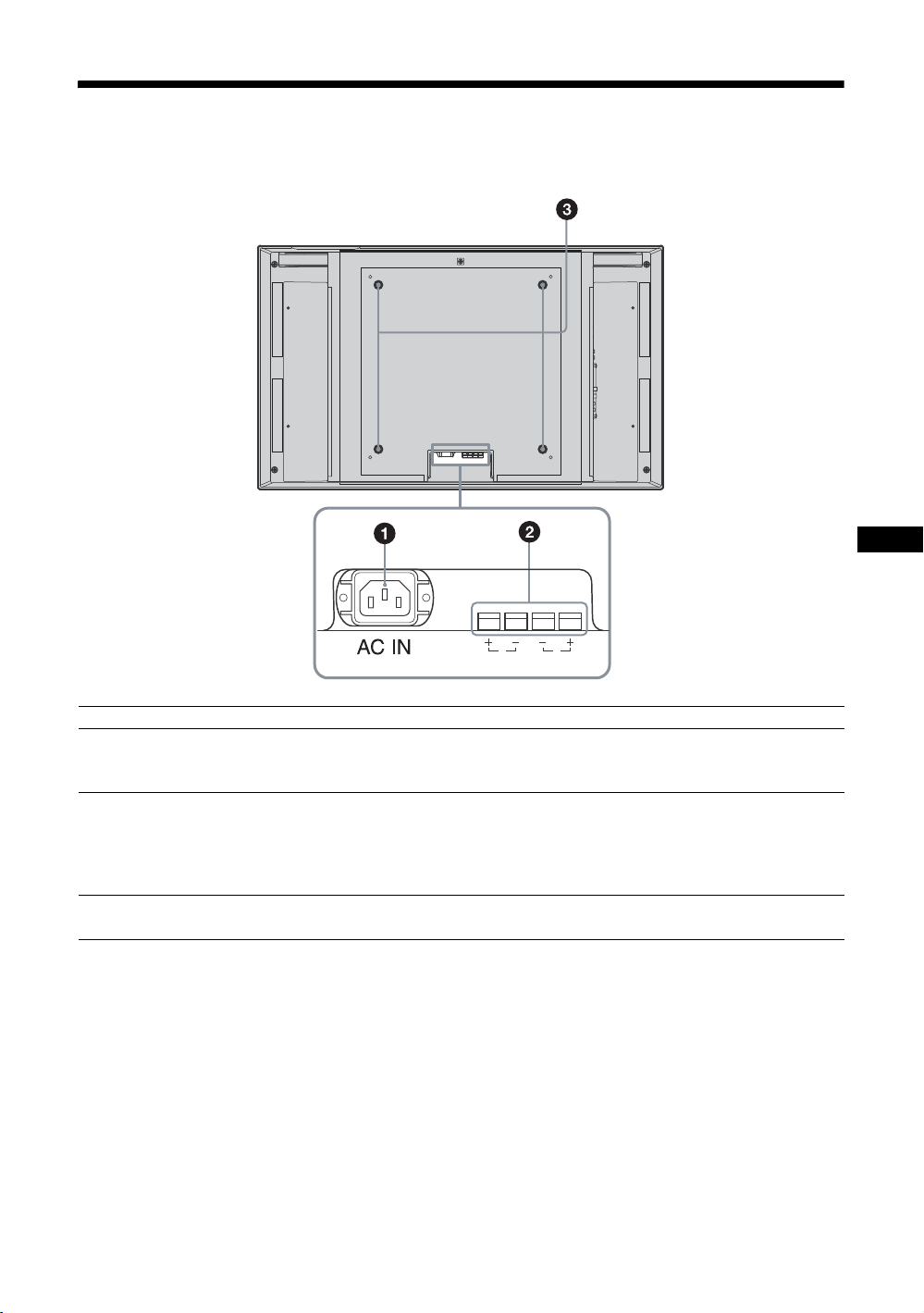
Panneau arrière
R
SPEAKER
FR
L
Pièces Description
1 Prise AC IN Raccordez le cordon d’alimentation secteur fourni à cette prise et à une prise murale. Une
fois le cordon d’alimentation raccordé, l’indicateur POWER/STANDBY s’allume en
rouge et l’écran passe en mode de veille. Voir page 17.
2 Prise SPEAKER Connectez les enceintes SS-SP40FW/32FW (non fournies) à cette prise pour émettre un
signal audio correspondant à celui affiché sur l’écran. Vous bénéficiez ainsi d’un
visionnage plus performant. Assurez-vous de raccorder les enceintes correctement. Pour
plus d’informations sur le raccordement des enceintes, reportez-vous à leur mode
d’emploi. Pour plus de détails sur le cheminement des cordons d’enceintes, voir page 19.
3 Crochets d’installation du
support
Utilisez ces crochets pour installer le support d’écran SU-42FW/32FW (non fourni).
11
FR
Page 88

HDMI2
ON
STANDBY
HD15
ID MODE
OFF
SET
OPTION1
DISPLAY
ECO
SOUND
PICTURE
OPTION2
HDMI1
RM-FW001
Télécommande
Description des touches
ON
HDMI2
PICTURE
SOUND
OFF
SET
STANDBY
HD15
OPTION1
OPTION2
DISPLAY
ECO
ONONID MODE
HDMI1
RM-FW001
1 Commutateur POWER ON
Appuyez sur ce commutateur pour mettre l’écran sous tension.
2 Touche HDMI 1/HDMI 2
Appuyez sur cette touche pour sélectionner le signal émis vers les
connecteurs HDMI 1 ou HDMI 2.
3 Touche
Appuyez sur cette touche pour modifier le format en « Mode
cinéma ». Voir page 14.
4 Touche
Permet de sélectionner le mode « PAP » (Picture And Picture).
Chaque pression sur cette touche permet de basculer entre l’écran à
deux images et l’écran à une image. Voir page 15.
5 Touche PICTURE
Permet de sélectionner le « Mode de l’image ». Chaque pression sur
cette touche permet de basculer entre « Éclatant », « Standard »,
« Personnalisé » et « TC Control ».
6 Touche F/f/G/g/
Les touches F/f/G/g permettent de déplacer le curseur (jaune) du
menu et de régler des paramètres, etc. Appuyez sur pour valider
le menu ou le réglage sélectionné.
En mode « PAP », vous pouvez commuter l’image active à l’aide de
G/g.
7 Touche SOUND
Permet de sélectionner le « Mode du son ». Chaque pression sur cette
touche permet de basculer entre « Dynamique », « Standard », « SRS
WOW » et « Personnalisé ».
8 Touche MENU
Appuyez sur cette touche pour afficher les menus. Appuyez de
nouveau pour les masquer. Voir page 20.
Remarques
• Les touches 5 et comportent un point tactile. Utilisez le point tactile comme repère lors de l’utilisation de l’écran.
• Introduisez deux piles AA (R6) (fournies) en faisant correspondre la polarité 3 et # des piles avec celle du logement des piles.
Pour ouvrir, appuyez
et faites glisser
,
12
FR
Page 89

HDMI2
ON
STANDBY
HD15
ID MODE
OFF
SET
OPTION1
DISPLAY
ECO
SOUND
PICTURE
OPTION2
HDMI1
RM-FW001
STANDBY
HD15
OPTION1
OPTION2
DISPLAY
ECO
ONONID MODE
HDMI1
RM-FW001
HDMI2
PICTURE
OFF
SET
ON
SOUND
9 Touches ID MODE (ON/0-9/SET/C/OFF)
Vous pouvez faire fonctionner un écran particulier sans affecter
d’autres écrans installés en même temps.
• Touche ON : Appuyez sur cette touche pour afficher le « Numéro
d’index » à l’écran.
• Touches 0 à 9 : Appuyez sur ces touches pour saisir le « Numéro
d’index » de l’écran que vous souhaitez faire fonctionner.
• Touche SET : Appuyez sur cette touche pour valider le « Numéro
d’index » saisi.
• Touche C : Appuyez sur cette touche pour effacer le « Numéro
d’index » saisi.
• Touche OFF : Appuyez sur cette touche pour revenir en mode
normal.
Voir page 16.
0 Touche +/–
Permet de régler le niveau de l’image (contraste).
qa Touche +/–
Appuyez sur cette touche pour régler le volume.
qs Touche
Appuyez sur cette touche pour couper le son. Appuyez de nouveau
pour restaurer le son.
qd Touche ECO
Appuyez sur cette touche pour réduire la consommation d’énergie en
réglant la luminosité de l’écran. Ce réglage permet également
d’augmenter le niveau de noir. Permet de sélectionner entre « Non »,
« Bas », « Haut » ou « Image désactivée ». Voir page 16.
qf Touche DISPLAY
Appuyez sur cette touche pour afficher l’entrée actuellement
sélectionnée ainsi que le type du signal d’entrée et le réglage « Mode
cinéma » à l’écran. Appuyez de nouveau pour les masquer. Si les
informations restent affichées pendant quelques instants, elles
disparaissent automatiquement.
qg Touche OPTION 1/OPTION 2
Si un adaptateur en option est inséré, permet de sélectionner un signal
à émettre à partir de l’appareil raccordé à l’adaptateur en option.
Appuyez sur la touche OPTION 1 pour sélectionner le signal d’entrée
du connecteur OPTION 1, puis appuyez sur la touche OPTION 2
pour sélectionner le signal d’entrée du connecteur OPTION 2.
qh Touche HD15
Appuyez sur cette touche pour sélectionner le signal d’entrée du
connecteur HD15. Le signal RVB ou le signal composante est
automatiquement sélectionné selon l’appareil raccordé.
qj Touche STANDBY
Appuyez sur cette touche pour mettre l’écran en mode de veille.
FR
13
FR
Page 90

Touches spéciales de la télécommande
Utilisation du Mode cinéma
Vous pouvez modifier le format de l’écran.
Conseil
Vous pouvez également accéder aux réglages « Mode
cinéma » dans les réglages « Écran ». Voir page 25, 29.
Mode cinéma
:
Grand zoom
Mode cinéma:
4:3
Mode cinéma:
Plein écran
Mode cinéma
:
Zoom
Pour une entrée vidéo, DVD ou HDMI (autre qu’une
entrée d’ordinateur)
Source d’origine 4:3
Source d’origine 16:9
m
Grand zoom
4:3
Plein écran
Grand
zoom
4:3
Plein écran
Zoom
Zoom
m
Remarque
Lorsque le signal d’entrée est en 1080i, 720p, ou 1080p, il est
impossible de sélectionner « Grand zoom » et « 4:3 ». Voir
page 25.
Pour entrée d’ordinateur
Normal
Plein
écran 1
Plein
écran 2
14
FR
Page 91
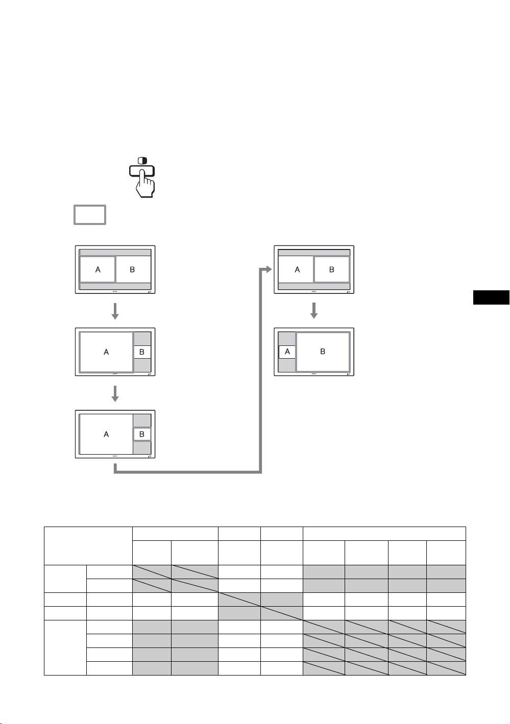
Utilisation du réglage PAP
Vous pouvez afficher côte à côte deux images
provenant de deux sources de signaux différentes,
telles qu’un ordinateur et un équipement vidéo.
Vous pouvez également intervertir les images gauche
et droite ou modifier la répartition de la taille des
images gauche et droite.
Conseil
Vous pouvez également accéder à l’option « Réglage PAP »
dans les réglages « Écran ». Voir page 27.
Curseur signalant l’image active
La largeur de A et B
est la même.
La hauteur est réglée
afin de correspondre
au format de chaque
image.
Appuyez sur la touche G.
La largeur de A est
supérieure à celle de B.
Si le format de A est
4:3, la hauteur de A est
égale à la taille de
l’écran.
Appuyez sur la touche g.
B, à droite, devient
l’image active.
Appuyez sur la touche g.
Appuyez sur la touche g.
La largeur de A et B est la
même.
La hauteur est réglée afin
de correspondre au format
de chaque image.
La largeur de B est
supérieure à celle de A.
Si le format de B est 4:3, la
hauteur de B est égale à la
taille de l’écran.
Combinaisons de deux images disponibles
HD15 HDMI 1 HDMI 2 OPTION 1 & 2
RVB Composante HDMI/
DVI
HD15 RVB
Composante aa
HDMI 1 HDMI/DVI aa aaaa
HDMI 2 HDMI/DVI aa aaaa
OPTION
1 & 2
RVB
Composante aa
Vidéo aa
S Video (S Vidéo)
aa
aa
aa
HDMI/
DVI
RVB
Composante
Vidéo S Video
(S Vidéo)
FR
15
FR
Page 92

Utilisation de la touche ID MODE
Vous pouvez faire fonctionner un écran particulier
sans affecter d’autres écrans installés en même temps.
1 Appuyez sur la touche ON.
Le « Numéro d’index » de l’écran s’affiche en
caractères noirs dans le menu inférieur gauche de
l’écran.
(Chaque écran possède un « Numéro d’index »
individuel préréglé compris entre 1 et 255.)
Numéro d’index
Numéro d’index
:
117
4 Lorsque toutes les modifications de
réglages sont terminées, appuyez sur la
touche OFF.
L’affichage revient à l’écran normal.
Correction du Numéro d’index
Appuyez sur la touche C pour effacer le « Numéro
d’index » saisi. Retournez à l’étape 2, puis saisissez
un nouveau « Numéro d’index ».
Conseil
Pour modifier le « Numéro d’index » de l’écran, reportezvous à « Index télécommande » dans « Réglage contrôle »,
page 31.
2 Saisissez le « Numéro d’index » de l’écran
que vous souhaitez faire fonctionner à
l’aide des touches 0 à 9 de la
télécommande.
Le numéro saisi s’affiche à droite du « Numéro
d’index » de chaque écran.
Numéro saisi
Numéro d’index
:
117
117
3 Appuyez sur la touche SET.
Les caractères sur l’écran sélectionné deviennent
verts, tandis que les autres deviennent rouges.
Vous pouvez faire fonctionner l’écran particulier
repéré par les caractères verts uniquement.
Seuls le commutateur POWER ON et la touche
STANDBY/ID MODE-OFF fonctionnent
également avec d’autres écrans.
Utilisation de la fonction Mode ECO
Vous pouvez réduire la consommation d’énergie de
l’écran.
ECO
Annulation du Mode ECO
Appuyez plusieurs fois sur la touche ECO jusqu’à ce
que « Mode ECO : Non » apparaisse.
Conseils
• Si vous mettez l’écran hors tension lorsque le « Mode
ECO » est activé, il est activé lors de la prochaine mise
sous tension de l’écran, sauf « Image désactivée ».
• Vous pouvez régler le « Mode ECO » à l’aide du menu
« Réglage ». Sélectionnez « Mode ECO » dans les
réglages « Réglage », puis réglez-le sur « Non », « Bas »,
« Haut » ou « Image désactivée ».
Mode ECO:
Non
Mode ECO:
Bas
Mode ECO:
Haut
Mode ECO:
Image désactivée
16
FR
Page 93

Raccordements
Avant de commencer
• Assurez-vous dans un premier temps que tous les
appareils sont hors tension.
• Utilisez des câbles adaptés aux appareils à raccorder.
• Insérez les câbles à fond dans les connecteurs ou les
prises. Une connexion lâche risque de provoquer du
souffle ou d’autres parasites.
• Pour débrancher le câble, saisissez-le par la fiche. Ne tirez
jamais sur le câble lui-même.
• Consultez également le mode d’emploi de l’appareil à
raccorder.
• Insérez bien le connecteur dans la prise AC IN
• Utilisez l’un des deux supports de la prise secteur (fournis)
qui maintiennent en place la prise secteur.
Raccordement des
enceintes
Raccordement de la
prise d’alimentation
secteur
1 Branchez le cordon d’alimentation secteur
dans la prise AC IN. Fixez ensuite le
support de la prise secteur (fourni) au
cordon d’alimentation secteur.
Vous pouvez bénéficier d’une ambiance plus réelle en
raccordant les enceintes SS-SP40FW/32FW (non
fournies). Assurez-vous de raccorder les enceintes
correctement. Pour plus de détails sur le raccordement
des enceintes, reportez-vous à leur mode d’emploi.
Pour plus de détails sur le cheminement des cordons
d’enceintes, voir page 19.
Prise
Cordon
d’alimentation
secteur
Support
de la prise
secteur
AC IN
2 Faites glisser le support de la prise secteur
par-dessus le cordon jusqu’à ce qu’il
s’enclenche dans le logement de la prise
AC IN.
Logement de la
prise AC IN
FR
Pour retirer le cordon d’alimentation secteur
Après avoir exercé une pression sur le support de la
prise secteur pour le libérer, saisissez la prise et tirez
le cordon d’alimentation secteur.
17
FR
Page 94

Gestion des câbles
Un cache-câbles est situé à l’arrière de l’écran pour lui donner un aspect bien net. Avant de raccorder les câbles à
l’écran, tirez sur le cache-câbles pour l’ouvrir, comme illustré ci-dessous. Une fois les câbles raccordés à l’écran,
refermez le cache-câbles.
Cache-câbles
(partie inférieure)
Cache-câbles
(côté)
18
FR
Page 95

Utilisation des supports de câbles
Vous pouvez regrouper les câbles à l’aide des supports de câble fournis.
Fixez les supports de câble comme illustré ci-dessous.
Pour le FWD-40LX2F/40LX2X :
Fixez les deux supports de câble (× 4 fournis) respectivement dans les fentes en haut et en bas.
Lorsque vous raccordez les enceintes (non fournies), faites passer les cordons d’enceinte dans les supports de câble
à l’arrière de l’écran.
Pour le FWD-32LX2F/32LX2X :
Choisissez six orifices parmi les huit (4 dessus et 4 dessous) et fixez les supports de câble (× 6 fournis). Les supports
de câble des enceintes ne sont pas fournis.
FWD-32LX2F/32LX2X
Support de câbles
Insérez le support de
câble dans l’orifice
prévu à cet effet sur
l’écran et faites-le
tourner de 90 degrés.
Support de
cordon d’enceinte
(uniquement pour
le FWD-40LX2F/
40LX2X)
Arrière
FWD-40LX2F/40LX2X
Support de câbles
Appuyez sur
l’attache pour
ouvrir les griffes
de fixation.
Insérez le support
de câbles dans
les orifices.
FR
19
FR
Page 96

Utilisation des réglages
Description générale des menus
1 Appuyez sur la touche MENU.
2 Appuyez sur F/f pour sélectionner l’icône
du menu de votre choix.
3 Appuyez sur ou g.
Pour quitter le menu, appuyez sur la touche
MENU.
2,3
Pour modifier la langue affichée à l’écran
Sélectionnez la langue d’affichage souhaitée pour les
messages et les menus parmi les langues suivantes :
1
Les réglages permettent d’accéder aux fonctions suivantes :
Réglages Pour effectuer des réglages ou des modifications
Image
Image
Mode de l'image : Éclatant
Réinit. mode image
Contraste : 50
Luminosité : 40
Couleur : 60
Nuance : 0
Temp. couleur : Froide
Netteté : 18
Réduction du bruit : Oui
CineMotion : Auto
True Color Control
Sél: Sortie:
Régl:
Son
Son
Mode du son : Dyna mique
Réinit. mode son
Aigu :
Grave :
Balance :
Sélect. son commun :
Sortie haut-p. : Oui
Préc:
Centre
HD 15
HDMI 1
MENU
HDMI 1
Mode de l’image (page 22, 23)
Réinit. mode image (page 22, 23)
Contraste (page 22, 23)
Luminosité (page 22, 23)
Couleur (page 22)
Nuance (page 22)
Temp. couleur (page 22, 23)
Netteté (page 22)
Réduction du bruit (page 22)
CineMotion (page 22)
True Color Control (page 23)
Mode du son (page 24)
Réinit. mode son (page 24)
Aigu (page 24)
Grave (page 24)
Balance (page 24)
Sélect. son commun (page 24)
Sortie haut-p. (page 24)
« English », « Español », « Français », « Italiano »,
« Deutsch » ou « ».
« English » (l’anglais) est la langue par défaut. Voir
page 30.
Sél: Sortie:
FR
20
Régl:
Préc:
MENU
Page 97

Réglages Pour effectuer des réglages ou des modifications
Écran
Écran
Mode cinéma : Grand zoom
Auto cinéma : Oui
4:3 par défaut : Grand zoom
Zone d'affichage : Normal
Réglage automatique
Phase :
Espacement :
Pos. horizontale :
Pos. verticale :
Taille verticale :
Réinitialiser
Réglage PAP
Affichage multiple
Sél: Sortie:
Régl:
Préc:
HDMI 1
0
0
0
MENU
Mode cinéma (page 25, 29)
Auto cinéma (page 25)
4:3 par défaut (page 26)
Zone d’affichage (page 26)
Réglage automatique (page 29)
Phase (page 29)
Espacement (page 29)
Pos. horizontale (page 26, 29)
Pos. verticale (page 26, 29)
Taille verticale (page 26)
Réinitialiser (page 26, 29)
Réglage PAP (page 27)
Affichage multiple (page 28)
Réglage
Réglage
Langue : Français
Régl. minuterie
Mode ECO : Non
Arrêt auto :
Réglages avancés
Informations
Tout réinitialiser
IP Address Setup
Speed Setup
HDMI 1
Non
Langue (page 30)
Régl. minuterie (page 30)
Mode ECO (page 30)
Arrêt auto (page 30)
Réglages avancés (page 31)
Informations (page 31)
Tout réinitialiser (page 32)
IP Address Setup (page 32)
Sél: Sortie:
Régl:
Préc:
MENU
Speed Setup (page 32)
* Il est possible que les icônes de menu affichées en bas de l’écran ne fonctionnent pas selon les réglages.
FR
21
FR
Page 98

Réglages Image
Pour l’entrée vidéo
Image
Mode de l'image : Vivid
Réinit. mode image
Contraste :
Luminosité :
Couleur :
Nuance :
Temp. couleur :
Netteté :
Réduction du bruit :
CineMotion :
True Color Control
Éclatant
Standard
Max
Personnalisé
40
TC Control
60
0
Froide
18
Oui
Auto
HDMI 1
Pour sélectionner une option et changer le réglage,
appuyez sur
F/f/G/g.
Appuyez sur pour confirmer votre choix.
Les réglages « Image » comprennent les options
suivantes :
Sél: Sortie:
Régl:
Préc:
Mode de l’image
Réinit. mode image
Contraste
Luminosité
Couleur
Nuance
Temp. couleur
MENU
« Éclatant » : pour sélectionner un réglage maximal des contrastes et de la netteté de
l’image.
« Standard » : pour sélectionner un réglage moyen de l’image
« Personnalisé » : pour mémoriser vos réglages personnels.
« TC Control » : le réglage est commun avec «Éclatant». Vous pouvez également
utiliser la fonction « True Color Control » (mentionnée ci-après).
Conseils
• Pour passer de l’option « Mode de l’image » à une autre, utilisez la touche PICTURE de la
télécommande.
• Vous pouvez modifier les options « Mode de l’image » pour chaque entrée.
Permet de réinitialiser tous les réglages à leurs valeurs par défaut pour le « Mode de
l’image » (« Éclatant », « Standard », « Personnalisé », « TC Control ») (sauf pour
les options grisées).
A utiliser pour augmenter ou diminuer le contraste de l’image.
A utiliser pour augmenter ou diminuer la luminosité de l’image.
A utiliser pour augmenter ou diminuer l’intensité des couleurs.
A utiliser pour régler les tons des couleurs de l’image.
Remarque
L’option « Nuance » n’est pas disponible lorsque l’entrée est de type vidéo ou S Video
(S Vidéo) et que le standard couleur du signal vidéo n’est pas de type NTSC.
« Froide » : sélectionnez pour donner une teinte bleuâtre aux couleurs blanches.
« Neutre » : sélectionnez pour donner une teinte neutre aux couleurs blanches.
« Chaude » : sélectionnez pour donner une teinte rougeâtre aux couleurs blanches.
Netteté
Réduction du bruit
CineMotion
FR
22
A utiliser pour augmenter ou diminuer la netteté de l’image.
Sélectionnez pour réduire le niveau de bruit de l’appareil raccordé. Sélectionnez
« Oui » ou « Non ».
Sélectionnez « Auto » pour optimiser la lecture de l’image filmée qui est
automatiquement détectée et ajustée selon un processus d’ajustement inversé de
l’image 3-2 ou 2-2. Les images dynamiques apparaitront alors plus nettes et plus
naturelles. Sélectionnez « Non » pour désactiver la détection.
Page 99

True Color Control
Vous pouvez régler les nuances et la saturation pour chacune des 4 couleurs : rouge,
vert, jaune et bleu. Vous pouvez également mettre en surbrillance certaines couleurs
de l’image.
Sélectionnez la couleur que vous souhaitez régler, puis vérifiez quelle partie de
l’image affichée sera réglée. Réglez-la ensuite à l’aide de la boîte de dialogue
Matrice.
Remarques
• Vous pouvez régler cette option lorsque « Mode de l’image » est réglé sur « TC Control ».
• En mode « PAP », vous ne pouvez pas sélectionner cette option. Même si vous sélectionnez
cette option dans l’écran à une image, il est possible que le réglage de cette option ne soit pas
appliqué en mode « PAP ».
Conseil
Vous pouvez modifier les réglages « Image » (« Contraste », « Luminosité », « Couleur » etc.) pour chaque « Mode de l’image ».
Remarques
• En mode «
• Si aucun signal n’est en cours de transmission, aucune option du réglage « Image » ne peut être sélectionnée.
PAP », aucune des options de réglage « Image » ne peut être sélectionnée.
Pour une entrée d’ordinateur
Image
Mode de l'image : Éclatant
Réinit. mode image
Contraste : 50
Luminosité : 40
Couleur :
Nuance :
Temp. couleur : Neutre
Netteté :
Réduction du bruit :
CineMotion :
True Color Control
HD15 RGB
Lorsque l’entrée est commutée sur une source
d’entrée de l’ordinateur, les réglages « Image »
spécifiques à l’entrée de l’ordinateur sont appliqués.
Les réglages « Image » pour l’ordinateur incluent les
options suivantes :
FR
Sél: Sortie:
Régl:
Préc:
Mode de l’image
MENU
« Éclatant » : pour sélectionner un réglage maximal des contrastes et de la netteté de
l’image.
« Standard » : pour sélectionner un réglage moyen de l’image.
«Personnalisé » : pour mémoriser vos réglages personnels.
« TC Control » : le réglage est commun avec «Éclatant». Vous pouvez également
utiliser la fonction « True Color Control » (mentionnée ci-après).
Réinit. mode image
Permet de réinitialiser tous les réglages à leurs valeurs par défaut pour le « Mode de
l’image » (« Éclatant », « Standard », « Personnalisé », « TC Control ») (sauf pour
les options grisées).
Contraste
Luminosité
Temp. couleur
True Color Control
Remarques
• « Couleur », « Nuance », « Netteté », « Réduction du bruit » et « CineMotion» ne sont pas disponibles pour une entrée d’ordinateur.
• En mode «
• Si aucun signal n’est en cours de transmission, aucune option du réglage « Image » ne peut être sélectionnée.
PAP », aucune option du réglage « Image » ne peut être sélectionnée.
A utiliser pour augmenter ou diminuer le contraste de l’image.
A utiliser pour augmenter ou diminuer la luminosité de l’image.
Reportez-vous à « Temp. couleur » pour l’entrée vidéo (page 22).
Reportez-vous à « True Color Control » pour l’entrée vidéo (page 23).
23
FR
Page 100

Réglages Son
Son
Mode du son : Dyna mic
Réinit. mode son
Aigu :
Grave :
Balance :
Sélect. son commun :
Sortie haut-p. : Oui
Sél: Sortie:
Régl:
Dynamique
Standard
SRS WOW
Pers onnalisé
Centre
HD15
Préc:
Mode du son
Réinit. mode son
Aigu
HDMI 1
Lorsque les enceintes SS-SP40FW/32FW (non
fournies) sont installées, vous pouvez configurer
différents réglages du « Son ».
Pour sélectionner une option et changer le réglage,
appuyez sur
F/f/G/g.
Appuyez sur pour confirmer votre choix.
Les réglages « Son » comprennent les options
suivantes :
MENU
« Dynamique » : sélectionnez pour augmenter les aigus et les graves.
«Standard»: réglage plat,
« SRS WOW » : procure une image audio et stéréo panoramique en produisant une
qualité sonore (pour les aigus et les graves) riche et intense. Ainsi, vous pouvez
profiter de puissants effets sonores identiques à ceux d’une salle de cinéma.
« Personnalisé » : vous permet de mémoriser vos réglages personnels.
Conseils
• Pour passer de l’option « Mode du son » à une autre, utilisez la touche SOUND de la
télécommande.
• Les technologies propriétaires de BBE Sound, Inc. sont appliquées pour les types
«Dynamique» et «Standard».
Permet de réinitialiser les réglages suivants : « Aigu », « Grave » et « Balance » afin
de revenir aux réglages par défaut.
A utiliser pour augmenter ou réduire le niveau des sons plus aigus.
Grave
Balance
Sélect. son commun
A utiliser pour augmenter ou réduire le niveau des sons plus graves.
A utiliser pour accentuer la balance de l’enceinte droite ou gauche.
« HD15 » : pour émettre l’audio à partir d’un appareil vidéo ou d’un ordinateur
raccordé au connecteur HD15 (RGB/COMPONENT IN) et au connecteur AUDIO
(COMMON AUDIO IN).
« HDMI 1 »/« HDMI 2 » : sélectionnez pour raccorder un appareil à l’aide d’un
câble HDMI (non fourni) ou d’un câble HDMI-DVI ainsi que le câble audio
correspondant en même temps.
Voir page 8.
Remarques
• Si vous utilisez un câble HDMI vers DVI (non fourni), raccordez le câble audio au
connecteur AUDIO (COMMON AUDIO IN).
« HDMI 1 »/« HDMI 2 » est sélectionné, l’audio numérique n’est pas émis à partir des
•Si
connecteurs HDMI. Lorsqu’un équipement vidéo doté d’un connecteur HDMI est raccordé
aux connecteurs HDMI 1/HDMI 2, réglez « Sélect. son commun » sur « HD15 ».
(Le réglage par défaut est « HD15 ».)
Sortie haut-p.
« Oui » : permet au son d’être émis à partir des enceintes.
« Non » : désactive le son émis à partir des enceintes.
Remarque
Si «Sortie haut-p.» est réglé sur «Non», «Mode du son», «Réinit. mode son», «Aigu»,
« Grave » et « Balance » ne peuvent pas être sélectionnés
Conseil
Vous pouvez régler les menus de qualité sonore (« Aigu » et « Grave ») lorsque « Mode du son » est réglé sur « Personnalisé ».
24
FR
 Loading...