

Page 1

4-484-004-11(1)
Digital 4K Video
Camera Recorder
FDR-AX1/AX1E
Operating Guide
Before operating the unit, please read this manual thoroughly
and retain it for future reference.
© 2013 Sony Corporation
Page 2

Owner’s Record
The model and serial numbers are located on the
bottom. Record the serial number in the space
provided below. Refer to these numbers
whenever you call your Sony dealer regarding
this product.
Model No. FDR-
Serial No.
Model No. AC-
Serial No.
WARNING
To reduce the risk of fire or electric shock,
1) do not expose the unit to rain or moisture.
2) do not place objects filled with liquids, such
as vases, on the apparatus.
Do not expose the batteries to excessive heat
such as sunshine, fire or the like.
This symbol is intended to alert
the user to the presence of
uninsulated “dangerous
voltage” within the product’s
enclosure that may be of
sufficient magnitude to
constitute a risk of electric shock
to persons.
This symbol is intended to alert
the user to the presence of
important operating and
maintenance (servicing)
instructions in the literature
accompanying the appliance.
2
Page 3

IMPORTANT SAFETY INSTRUCTIONS
SAVE THESE INSTRUCTIONS.
DANGER - TO REDUCE THE RISK OF FIRE OR
ELECTRIC SHOCK, CAREFULLY FOLLOW
THESE INSTRUCTIONS.
• Read these instructions.
• Keep these instructions.
• Heed all warnings.
• Follow all instructions.
• Do not use this apparatus near water.
• Clean only with dry cloth.
• Do not block any ventilation openings. Install in accordance with the manufacturer’s instructions.
• Do not install near any heat sources such as radiators, heat registers, stoves, or other apparatus (including
amplifiers) that produce heat.
• Do not defeat the safety purpose of the polarized or grounding-type plug. A polarized plug has two
blades with one wider than the other. A grounding type plug has two blades and a third grounding prong.
The wide blade or the third prong are provided for your safety. If the provided plug does not fit into your
outlet, consult an electrician for replacement of the obsolete outlet.
• Protect the power cord from being walked on or pinched particularly at plugs, convenience receptacles,
and the point where they exit from the apparatus.
• Only use attachments/accessories specified by the manufacturer.
• Use only with the cart, stand, tripod, bracket, or table specified by the manufacturer, or sold with the
apparatus. When a cart is used, use caution when moving the cart/apparatus combination to avoid injury
from tip-over.
• Unplug this apparatus during lightning storms or when unused for long periods of time.
• Refer all servicing to qualified service personnel. Servicing is required when the apparatus has been
damaged in any way, such as power-supply cord or plug is damaged, liquid has been spilled or objects
have fallen into the apparatus, the apparatus has been exposed to rain or moisture, does not operate
normally, or has been dropped.
• If the shape of the plug does not fit the power outlet, use an attachment plug adaptor of the proper
configuration for the power outlet.
3
Page 4

Representative plug of power supply cord of countries/regions around the world.
A Type
(American
Type)
B Type
(British Type)
BF Type
(British Type)
B3 Type
(British Type)
C Type
(CEE Type)
SE Type
(CEE Type)
The representative supply voltage and plug type are described in this chart.
Depend on an area, Different type of plug and supply voltage are used.
Attention: Power cord meeting demands from each country shall be used.
—For only the United States
Use a supplied power cord.
Europe
Countries/regions Voltage Frequency (Hz) Plug type
Austria
Belgium
Czech
Denmark
Finland
France
Germany
Greece
Hungary
Iceland
Ireland
Italy
Luxemburg
Netherlands
Norway
Poland
Portugal
Romania
Russia
Slovak
Spain
Sweden
Switzerland
UK
230
230
220
230
230
230
230
220
220
230
230
220
230
230
230
220
230
220
220
220
127/230
230
230
240
50
50
50
50
50
50
50
50
50
50
50
50
50
50
50
50
50
50
50
50
50
50
50
50
C
C
C
C
C
C
C
C
C
C
C/BF
C
C
C
C
C
C
C
C
C
C
C
C
BF
O Type
(Ocean Type)
Asia
Countries/regions Voltage Frequency (Hz) Plug type
China
Hong Kong
India
Indonesia
Japan
Korea (rep)
Malaysia
Philippines
Singapore
Tai wan
Thailand
Vietnam
220
200/220
230/240
127/230
100
220
240
220/230
230
110
220
220
50
50
50
50
50/60
60
50
60
50
60
50
50
4
A
BF
C
C
A
C
BF
A/C
BF
A
C/BF
A/C
Page 5

Oceania
Countries/regions Voltage Frequency (Hz) Plug type
Australia
New Zealand
240
230/240
50
50
O
O
North America
Countries/regions Voltage Frequency (Hz) Plug type
Canada
USA
120
120
60
60
A
A
Central America
Countries/regions Voltage Frequency (Hz) Plug type
Bahamas
Costa Rica
Cuba
Dominican (rep)
El Salvador
Guatemala
Honduras
Jamaica
Mexico
Nicaragua
Panama
120/240
110
110/220
110
110
120
110
110
120/127
120/240
110/220
60
60
60
60
60
60
60
50
60
60
60
A
A
A/C
A
A
A
A
A
A
A
A
South America
Countries/regions Voltage Frequency (Hz) Plug type
Argentina
Brazil
Chile
Colombia
Peru
Venezuela
220
127/220
220
120
220
120
50
60
50
60
60
60
C/BF/O
A/C
C
A
A/C
A
Middle East
Countries/regions Voltage Frequency (Hz) Plug type
Iran
Iraq
Israel
Saudi Arabia
Turke y
UAE
220
220
230
127/220
220
240
50
50
50
50
50
50
C/BF
C/BF
C
A/C/BF
C
C/BF
Africa
Countries/regions Voltage Frequency (Hz) Plug type
Algeria
Congo (dem)
Egypt
Ethiopia
Kenya
Nigeria
South Africa
Tanzania
Tunisia
127/220
220
220
220
240
230
220/230
230
220
50
50
50
50
50
50
50
50
50
C
C
C
C
C/BF
C/BF
C/BF
C/BF
C
5
Page 6

CAUTION
Battery pack
If the battery pack is mishandled, the battery pack
can burst, cause a fire or even chemical burns.
Observe the following cautions.
• Do not disassemble.
• Do not crush and do not expose the battery pack
to any shock or force such as hammering,
dropping or stepping on it.
• Do not short circuit and do not allow metal
objects to come into contact with the battery
terminals.
• Do not expose to high temperature above 60°C
(140°F) such as in direct sunlight or in a car
parked in the sun.
• Do not incinerate or dispose of in fire.
• Do not handle damaged or leaking lithium ion
batteries.
• Be sure to charge the battery pack using a
genuine Sony battery charger or a device that
can charge the battery pack.
• Keep the battery pack out of the reach of small
children.
• Keep the battery pack dry.
• Replace only with the same or equivalent type
recommended by Sony.
• Dispose of used battery packs promptly as
described in the instructions.
Replace the battery with the specified type only.
Otherwise, fire or injury may result.
AC Adaptor
Do not use the AC Adaptor placed in a narrow
space, such as between a wall and furniture.
Use the nearby wall outlet (wall socket) when
using the AC Adaptor. Disconnect the AC
Adaptor from the wall outlet (wall socket)
immediately if any malfunction occurs while
using the apparatus.
Charger
Use the nearby wall outlet (wall socket) when
using the Charger. Disconnect the Charger from
the wall outlet (wall socket) immediately if any
malfunction occurs while using the apparatus.
Note on the power cord (mains lead)
The power cord (mains lead) is designed
specifically for use with this camcorder only, and
should not be used with other electrical
equipment.
Even if your camcorder is turned off, AC power
source (mains) is still supplied to it while
connected to the wall outlet (wall socket) via the
AC Adaptor.
Excessive sound pressure from earphones and
headphones cause hearing loss.
For customers in the U.S.A. and
CANADA
RECYCLING LITHIUM-ION
BATTERIES
Lithium-Ion batteries are
recyclable.
You can help preserve our
environment by returning your
used rechargeable batteries to the
collection and recycling location
nearest you.
For more information regarding
recycling of rechargeable batteries,
call toll free
1-800-822-8837, or visit
http://www.call2recycle.org/
Caution: Do not handle damaged
or leaking Lithium-Ion batteries.
Battery pack
This device complies with Part 15 of the FCC
Rules. Operation is subject to the following two
conditions:
(1) This device may not cause harmful
interference, and (2) this device must accept any
interference received, including interference that
may cause undesired operation.
6
Page 7

For the customers in the U.S.A.
UL is an internationally recognized safety
organization.
The UL Mark on the product means it has been
UL Listed.
If you have any questions about this product, you
may call:
Sony Customer Information Center 1-800-222SONY (7669).
The number below is for the FCC related matters
only.
Regulatory Information
Declaration of Conformity
Trade Name: SONY
Model No.: FDR-AX1
Responsible Party: Sony Electronics Inc.
Address: 16530 Via Esprillo, San Diego, CA
92127 U.S.A.
Telephone No.: 858-942-2230
This device complies with Part 15 of the FCC
Rules. Operation is subject to the following two
conditions: (1) This device may not cause
harmful interference, and (2) this device must
accept any interference received, including
interference that may cause undesired
operation.
CAUTION
You are cautioned that any changes or
modifications not expressly approved in this
manual could void your authority to operate this
equipment.
Note
This equipment has been tested and found to
comply with the limits for a Class B digital
device, pursuant to Part 15 of the FCC Rules.
These limits are designed to provide reasonable
protection against harmful interference in a
residential installation. This equipment generates,
uses, and can radiate radio frequency energy and,
if not installed and used in accordance with the
instructions, may cause harmful interference to
radio communications.
However, there is no guarantee that interference
will not occur in a particular installation. If this
equipment does cause harmful interference to
radio or television reception, which can be
determined by turning the equipment off and on,
the user is encouraged to try to correct the
interference by one or more of the following
measures:
—Reorient or relocate the receiving antenna.
—Increase the separation between the equipment and
receiver.
—Connect the equipment into an outlet on a circuit
different from that to which the receiver is connected.
—Consult the dealer or an experienced radio/TV
technician for help.
The supplied interface cable must be used with
the equipment in order to comply with the limits
for a digital device pursuant to Subpart B of Part
15 of FCC Rules.
For Customers in EUROPE
Notice for the customers in the countries
applying EU Directives
Manufacturer: Sony Corporation, 1-7-1 Konan
Minato-ku Tokyo, 108-0075 Japan
For EU product compliance: Sony Deutschland
GmbH, Hedelfinger Strasse 61, 70327 Stuttgart,
Germany
Notice
If static electricity or electromagnetism causes
data transfer to discontinue midway (fail), restart
the application or disconnect and connect the
communication cable (USB, etc.) again.
This product has been tested and found compliant
with the limits set out in the EMC Directive for
using connection cables shorter than 3 meters
(9.8 feet).
Attention
The electromagnetic fields at the specific
frequencies may influence the picture and sound
of this unit.
7
Page 8

Disposal of Old Electrical &
Electronic Equipment
(Applicable in the European
Union and other European
countries with separate
collection systems)
This symbol on the product or on its packaging
indicates that this product shall not be treated as
household waste. Instead it shall be handed over
to the applicable collection point for the recycling
of electrical and electronic equipment.
By ensuring this product is disposed of correctly,
you will help prevent potential negative
consequences for the environment and human
health, which could otherwise be caused by
inappropriate waste handling of this product. The
recycling of materials will help to conserve
natural resources.
For more detailed information about recycling of
this product, please contact your local Civic
Office, your household waste disposal service or
the shop where you purchased the product.
Disposal of waste batteries
(applicable in the European
Union and other European
countries with separate
collection systems)
This symbol on the battery or on the packaging
indicates that the battery provided with this
product shall not be treated as household waste.
On certain batteries this symbol might be used in
combination with a chemical symbol. The
chemical symbols for mercury (Hg) or lead (Pb)
are added if the battery contains more than
0.0005% mercury or 0.004% lead.
By ensuring these batteries are disposed of
correctly, you will help prevent potentially
negative consequences for the environment and
human health which could otherwise be caused
by inappropriate waste handling of the battery.
The recycling of the materials will help to
conserve natural resources.
In case of products that for safety, performance or
data integrity reasons require a permanent
connection with an incorporated battery, this
battery should be replaced by qualified service
staff only. To ensure that the battery will be
treated properly, hand over the product at end-of-
life to the applicable collection point for the
recycling of electrical and electronic equipment.
For all other batteries, please view the section on
how to remove the battery from the product
safely. Hand the battery over to the applicable
collection point for the recycling of waste
batteries.
For more detailed information about recycling of
this product or battery, please contact your local
Civic Office, your household waste disposal
service or the shop where you purchased the
product.
8
Page 9

Table of Contents
Overview
Preparations
Location and Function of Parts ............................................. 12
On-Screen Indications ............................................................ 19
LCD/viewfinder screen ................................................ 19
Power Supply ........................................................................... 21
Charging the battery pack ............................................ 21
Setting the Clock ..................................................................... 23
Attaching Devices .................................................................... 23
Attaching the lens hood with lens cover ...................... 23
Adjusting the LCD screen and viewfinder ................... 24
Using XQD Memory Cards .................................................... 25
About XQD memory cards .......................................... 25
Inserting an XQD memory card ................................... 25
Removing an XQD memory card ................................ 25
Selecting the memory card slot to be used for recording
................................................................................ 25
Formatting an XQD memory card ............................... 26
Checking the remaining time available for recording
................................................................................ 26
Recording
Basic Operation Procedure .................................................... 27
Changing Basic Settings ......................................................... 30
Recording format ......................................................... 30
Adjusting the image brightness .................................... 30
Adjusting to natural color (White balance) .................. 31
Audio setup .................................................................. 33
Useful Functions ...................................................................... 35
Assignable buttons ....................................................... 35
Table of Contents
9
Page 10

Thumbnail Screens
Settings
Thumbnail Screens ................................................................. 36
Configuration of the screen .......................................... 36
Playing Clips ............................................................................ 37
Playing the selected and subsequent clips in sequence
................................................................................ 37
Clip Operations ....................................................................... 37
Operations of the thumbnail menu ............................... 37
Displaying the detailed information of a clip ............... 38
Deleting clips ............................................................... 39
Changing information on the thumbnail screen ........... 39
Setup Menu Operations .......................................................... 40
Setup Menu List ...................................................................... 41
Camera menu ............................................................... 41
Paint menu .................................................................... 42
Audio menu .................................................................. 44
Video menu .................................................................. 44
LCD/VF menu .............................................................. 45
Media menu .................................................................. 46
System menu ................................................................ 46
Thumbnail menu .......................................................... 47
External Devices Connection
Table of Contents
10
Connecting External Monitors and Recording Devices ...... 48
Managing Clips with a Computer ......................................... 49
Connecting with a USB cable ...................................... 49
Playing Images on a Computer .............................................. 50
What you can do with “PlayMemories Home” software
(Windows) ............................................................. 50
Software for Mac .......................................................... 50
Checking the computer system .................................... 50
Installing the “PlayMemories Home” software in your
computer ................................................................ 50
Editing images on a computer ...................................... 51
Page 11

Appendices
Important Notes on Operation .............................................. 52
Recording time of movies ............................................ 52
Using your camcorder abroad ...................................... 54
Formats and Limitations of Outputs .................................... 59
Video formats and output signals ................................. 59
Error/Warning Indications .................................................... 61
Error indications ........................................................... 61
Warning indications ..................................................... 61
Licenses .................................................................................... 63
On accessing software to which the GPL/LGPL applies
................................................................................ 63
Open software licenses ................................................. 63
Specifications ........................................................................... 63
Package configuration .................................................. 65
Index ......................................................................................... 66
Table of Contents
11
Page 12

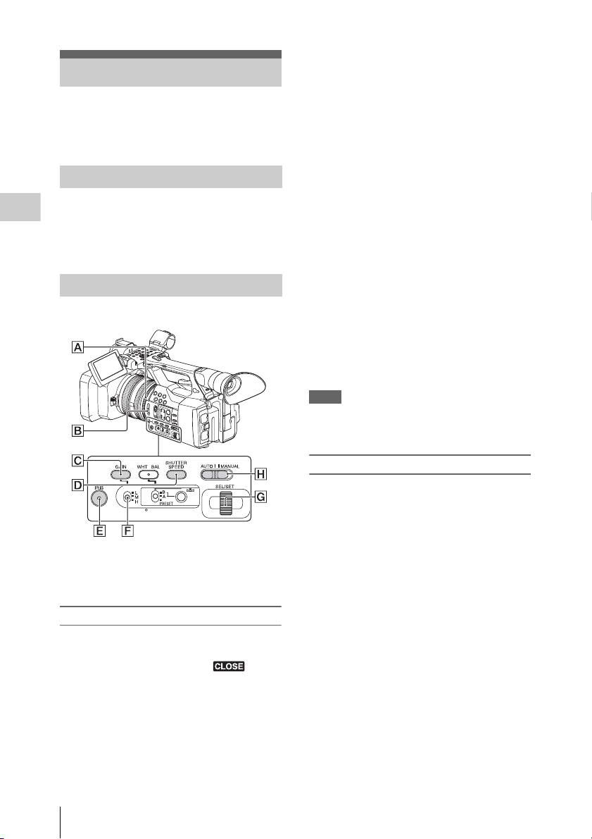
Overview
Overview
Location and Function of Parts
For functions and usage, see the pages in parentheses.
1. Hook for shoulder strap (15)
2. ASSIGN 7/FOCUS MAGNIFIER button
(35)
3. Microphone holder*
4. IRIS PUSH AUTO button
5. Power zoom lever (27)
* When you use the microphone, refer to the operating
instructions supplied with the microphone.
Location and Function of Parts
12
Page 13

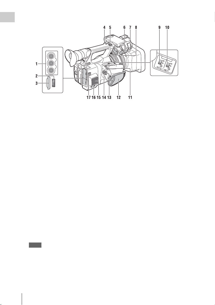
Overview
1. Lens (23)
2. Lens hood with lens cover (23)
3. Internal microphone (33)
4. Front recording lamp (46)
The recording lamp flashes if the remaining
capacity of recording media or battery is low.
5. ASSIGN 4/ZEBRA button
6. ASSIGN 1 button
7. ASSIGN 2 button*
8. ASSIGN 3 button
9. ASSIGN 6/THUMBNAIL button
10. CH1 (INT MIC/INPUT1/INPUT2) switch
11. AUTO/MAN (CH1) switch (34)
12. AUDIO LEVEL(CH1) dial (34)
13. STATUS CHECK button (16)
14. CANCEL/BACK button (40)
15. MENU button** (40)
16. AUDIO LEVEL(CH2) dial (34)
17. AUTO/MAN (CH2) switch (34)
18. CH2 (INT MIC/INPUT1/INPUT2) switch
(34)
19. PUSH AUTO button (28)
20. FOCUS switch (28)
21. ND FILTER switch (31)
22. ASSIGN 5/PEAKING button*
* The ASSIGN 5/PEAKING button and the ASSIGN 2
button have raised tactile dots for your convenience in
locating the button.
** MENU button has a raised tactile bar for your
convenience in locating the button.
Location and Function of Parts
13
Page 14
Overview
1. AUDIO OUT connectors/VIDEO OUT
connector (48, 60)
2. HDMI OUT connector (48)
3. UTILITY SD slot
(To be supported by future upgrade.)
4. Handle zoom lever (27)
5. START/STOP button
When the lever is set to the HOLD position, the
START/STOP button is not operable.
6. INPUT2 connector
7. INPUT1 connector
8. Cable holder
Provided for securing a microphone cable, etc.
9. INPUT2 switch (33)
10. INPUT1 switch (33)
11. REMOTE connector
The REMOTE connector is used for controlling
start/stop of recording, etc., on the video device
and peripherals connected to it.
12. Grip belt
13. POWER switch (27)
14. Record button (27)
15. Air outlet
Notes
• Areas around the exhaust vents may become hot.
• Do not cover the exhaust vents.
16. DC IN connector (22)
17. Cable holder
Provided for securing a DC cable, etc.
Location and Function of Parts
14
Page 15
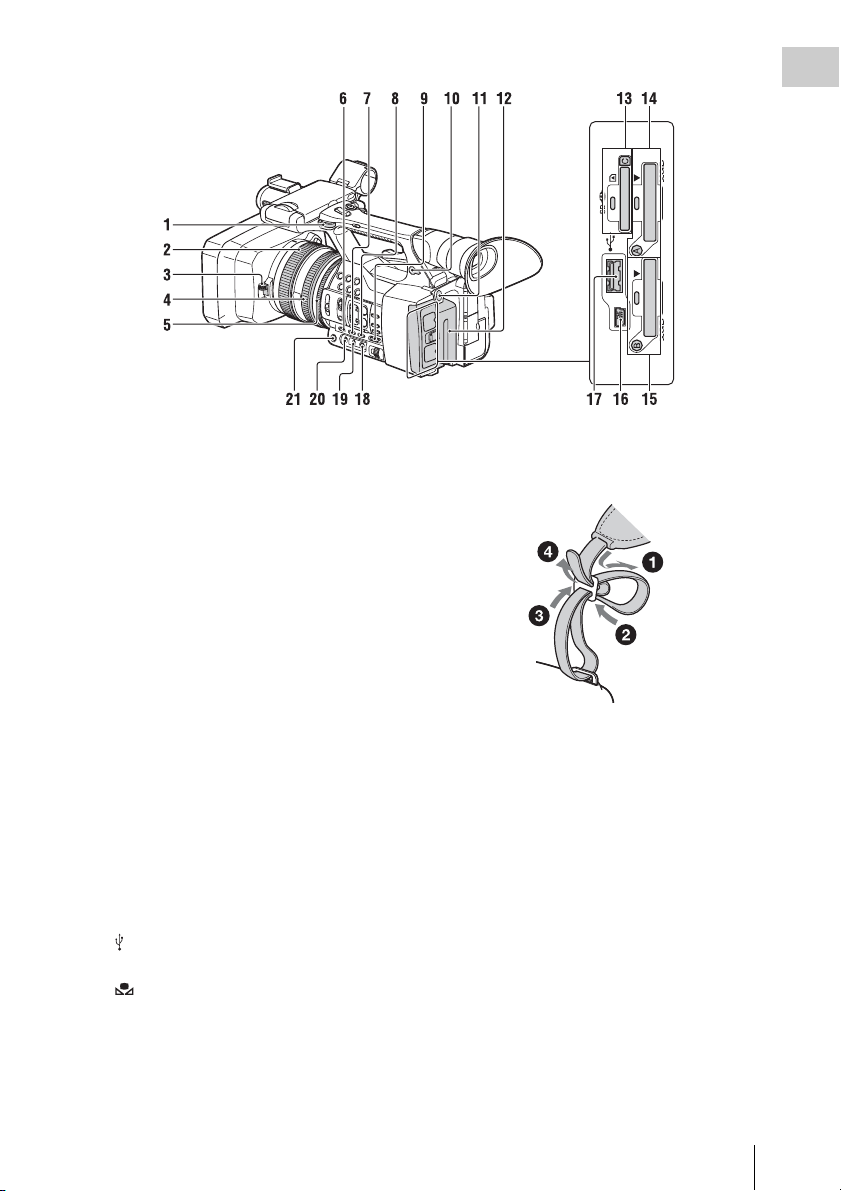
Overview
1. Hook for shoulder strap
2. Focus ring (28)
3. Lens cover lever (23)
4. Zoom ring (27)
5. Iris ring (30)
6. GAIN button (30)
7. WHT BAL button* (32)
8. SHUTTER SPEED button (31)
9. AUTO/MANUAL switch (30)
10. i (headphones) connector
For stereo mini-jack headphones
11. BATT RELEASE button (21)
12. Battery pack (21)
13. “Memory Stick” media/SD card C slot/
access lamp
(To be supported by future upgrade.)
14. XQD memory card A slot/select button/
access lamp (25)
15. XQD memory card B slot/select button/
access lamp (25)
16. USB connector (mini-B type) (49)
17. USB connector (A type)
(To be supported by future upgrade.)
18. (One push) button (31)
19. White balance memory switch (31)
20. Gain switch (30)
21. IRIS button* (30)
* WHT BAL and IRIS buttons have raised tactile dots
for your convenience in locating the buttons.
To attach a shoulder strap
Attach a shoulder strap (sold separately) to the
hooks for a shoulder strap.
Location and Function of Parts
15
Page 16
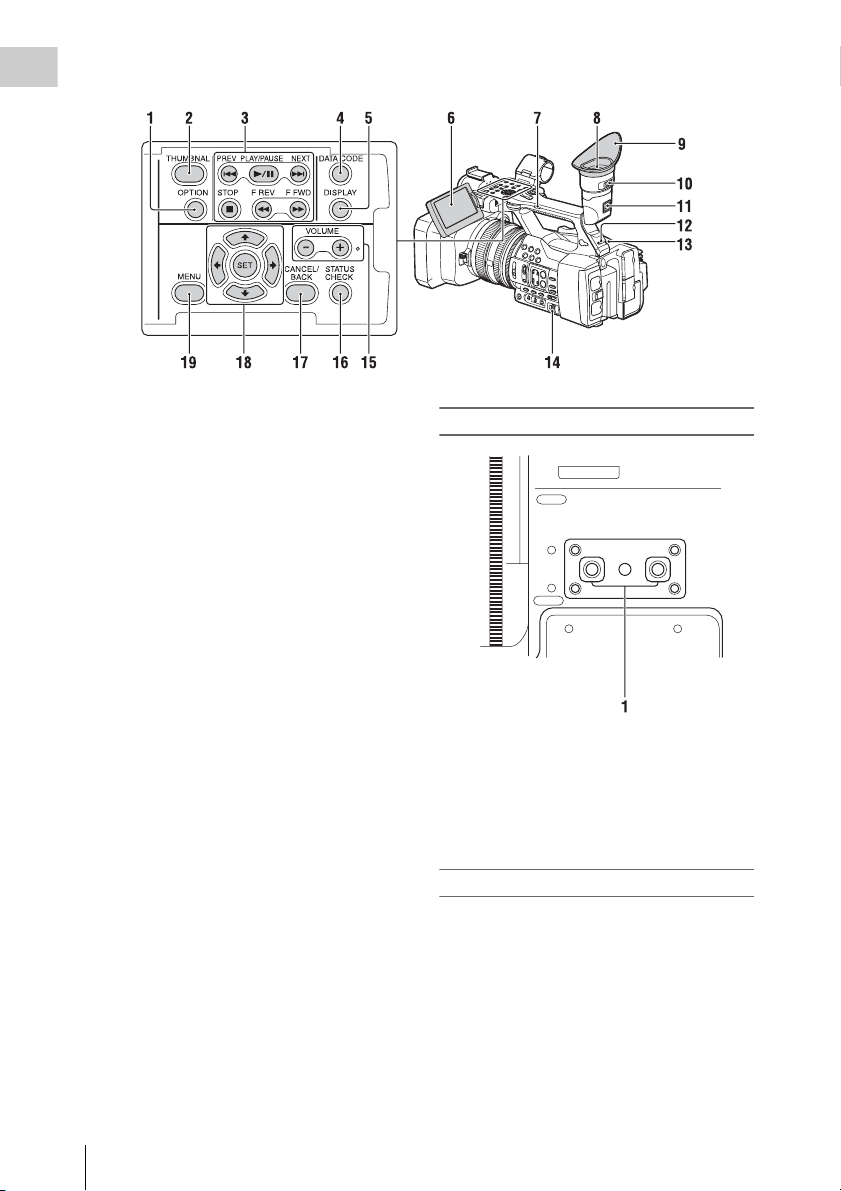
Overview
1. OPTION button (37)
2. THUMBNAIL button (36)
3. Playback control buttons (PREV, PLAY/
PAUSE*, NEXT, STOP, F REV, F FWD)
(28)
4. DATA CODE button
(To be supported by future upgrade.)
5. DISPLAY button (19)
6. LCD screen (24)
7. Handle zoom switch (27)
8. Viewfinder (24)
9. Large eyecup
10. Viewfinder lens adjustment lever (24)
11. Viewfinder release lever (57)
12. HEADPHONE MONITOR switch (34)
13. Rear recording lamp (46)
14. SEL/SET dial buttons (40)
15. VOLUME buttons*
16. STATUS CHECK button
17. CANCEL/BACK button (40)
18. V/v/B/b/SET buttons (40)
19. MENU button (40)
* VOLUME+ button and PLAY/PAUSE button have
raised tactile dots for your convenience in locating the
buttons.
Bottom
1. Tripod receptacle (1/4 inch)
This is a 1/4-20UNC screw compatible.
Attach a tripod (sold separately) to the tripod
receptacle using a tripod screw (sold
separately: the length of the screw must be
less than 5.5 mm (7/32 in.)).
Status screen
To display a status screen
• Press the STATUS CHECK button.
To switch status screens
• Turn the SEL/SET dial.
To hide the status screen
• Press the STATUS CHECK button.
Location and Function of Parts
16
Page 17

Camera status screen
Displays the electronic shutter settings or the
status of the lens.
Gain<H> Setting value of Gain <H>
level
Gain<M> Setting value of Gain <M>
level
Gain<L> Setting value of Gain <L>
level
Preset White Preset value of white balance
Gamma Gamma category and curve
AE Level Setting value of AE level
AE Speed Setting value of AE control
speed
AGC Limit Setting value of the maximum
gain of AGC
A.SHT Limit Fastest shutter speed of the
auto shutter function
Audio status screen
Displays the input settings for each channel,
audio level meter, and wind filter setting.
CH 1 level meter Level meter for CH 1
CH 1 Source Input source for CH 1
CH 1 Ref. / Sens. Sensitivity of the internal
microphone input to CH 1, or
the reference level of audio
input
CH 1 Wind Filter Setting status of the wind
filter for the microphone input
to CH 1
CH 2 level meter Level meter for CH 2
CH 2 Source Input source for CH 2
CH 2 Ref. / Sens. Sensitivity of the internal
microphone input to CH 2, or
the reference level of audio
input
CH 2 Wind Filter Setting status of the wind
filter for the microphone input
to CH 2
Audio Format Audio format setting
Headphone Out Headphone output setting
System status screen
Displays the video signal settings.
Country Setting status of the region,
NTSC region or PAL region
Rec Format Recording format that is
recorded on the XQD memory
card
Picture Size Picture size that is recorded on
the XQD memory card
Frame Rate Frame rate that is recorded on
the XQD memory card
Video output status screen
Displays the HDMI and video output settings.
HDMI Output picture size
Video Output picture size
Output On/Off
Assignable button status screen
Displays the function that is assigned to each
ASSIGN button.
1 Function that is assigned to
2 Function that is assigned to
3 Function that is assigned to
4 Function that is assigned to
5 Function that is assigned to
6 Function that is assigned to
7 Function that is assigned to
the Assign 1 button
the Assign 2 button
the Assign 3 button
the Assign 4 button
the Assign 5 button
the Assign 6 button
the Assign 7 button
Media status screen
Displays the remaining space of the recording
media (XQD memory card A/XQD memory
card B).
Media
information of
Media A
Protect
information of
Media A
Media icon displayed when
recording media is inserted in
the slot A
Protect icon displayed when
recording media inserted in
the slot A is write-protected
Notes
• You cannot protect the XQD
memory card on the
Remaining meter
of Media A
Remaining
capacity of
Media A
Media
information of
Media B
Protect
information of
Media B
Remaining meter
of Media B
camcorder.
Remaining capacity of the
recording media inserted in
the slot A, expressed with a
bar indicator
Remaining capacity of the
recording media inserted in
the slot A, expressed in GB
Media icon displayed when
recording media is inserted in
the slot B
Protect icon displayed when
recording media inserted in
the slot B is write-protected
Remaining capacity of the
recording media inserted in
the slot B, expressed with a
bar indicator
Overview
Location and Function of Parts
17
Page 18

Remaining
Overview
capacity of
Media B
Media
information of
the UTILITY SD
card
Protect
information of
the UTILITY SD
card
Remaining meter
of the UTILITY
SD card
Remaining
capacity of the
UTILITY SD
card
Remaining capacity of the
recording media inserted in
the slot B, expressed in GB
Media icon displayed when
recording media is inserted in
the UTILITY SD slot
Protect icon displayed when
the UTILITY SD slot is writeprotected
Remaining capacity of the
recording media inserted in
the UTILITY SD slot,
expressed by a bar indicator
Remaining capacity of the
recording media inserted in
the UTILITY SD slot,
expressed in GB
Location and Function of Parts
18
Page 19

On-Screen Indications
LCD/viewfinder screen
While recording, standing by to record, or playback, the statuses and settings of this unit are superimposed
on the LCD/viewfinder screen.
The statuses and settings of this unit can be turned on/off using the DISPLAY button.
Information displayed on the screen while recording
Overview
1. Shutter mode/shutter speed indication
2. ND filter indication (page 31)
3. Gain indication (page 30)
4. Special recording/operation status
indication
zRec Recording in progress
Stby Standby for recording
5. Color temperature indication (page 31)
6. Battery remaining indication (page 55)
7. Focus position indication
Displays focus position.
8. Zoom position indication
9. SteadyShot indication
10. Focus mode indication
11. Auto shutter indication
12. AGC indication
13. Auto iris indication
14. Iris position indication
Displays iris position.
15. White balance mode indication (page 31)
AT W Automatic mode
PWB Preset mode
Memory A Memory A mode
Memory B Memory B mode
n Preset mode (indoor)
Preset mode (outdoor)
16. UTILITY SD slot media status indication
17. Time data indication
18. Audio level meter
19. A/B slot media status/remaining space
indication (page 26)
When the left side of the icon is orange,
recording is possible.
When the green lamp on the upper right of the
icon lights, playback is possible.
20. Gamma indication (page 42)
Displays the gamma setting value.
21. Recording format (codec) indication
(page 30)
Displays the format that is recorded on an
XQD memory card.
On-Screen Indications
19
Page 20
22. System frequency and scan method
Overview
indication
23. Recording format (picture size) indication
(page 30)
Displays the picture size that is recorded on
an XQD memory card.
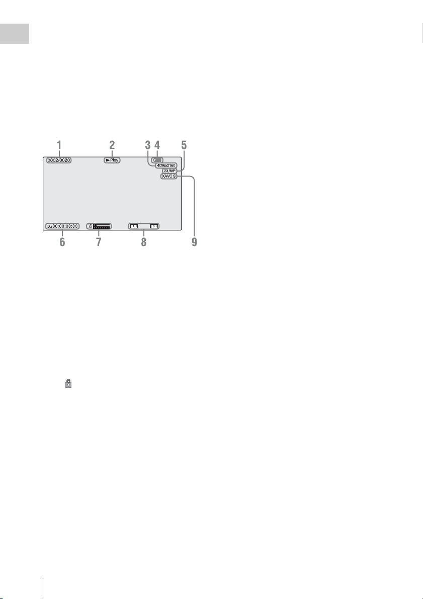
Information displayed on the playback screen
The following information is superimposed on
the playback picture.
1. Clip no./total number of clips
2. Playback mode
3. Playback format (picture size)
4. Battery remaining
5. Playback format (frame rate)
6. Time data
The duration of the movie is displayed.
7. Audio levels
The audio levels for the recording are displayed.
8. Media
A mark appears to the left if the memory
card is write-protected.
9. Playback format (codec)
On-Screen Indications
20
Page 21
Preparations
Power Supply
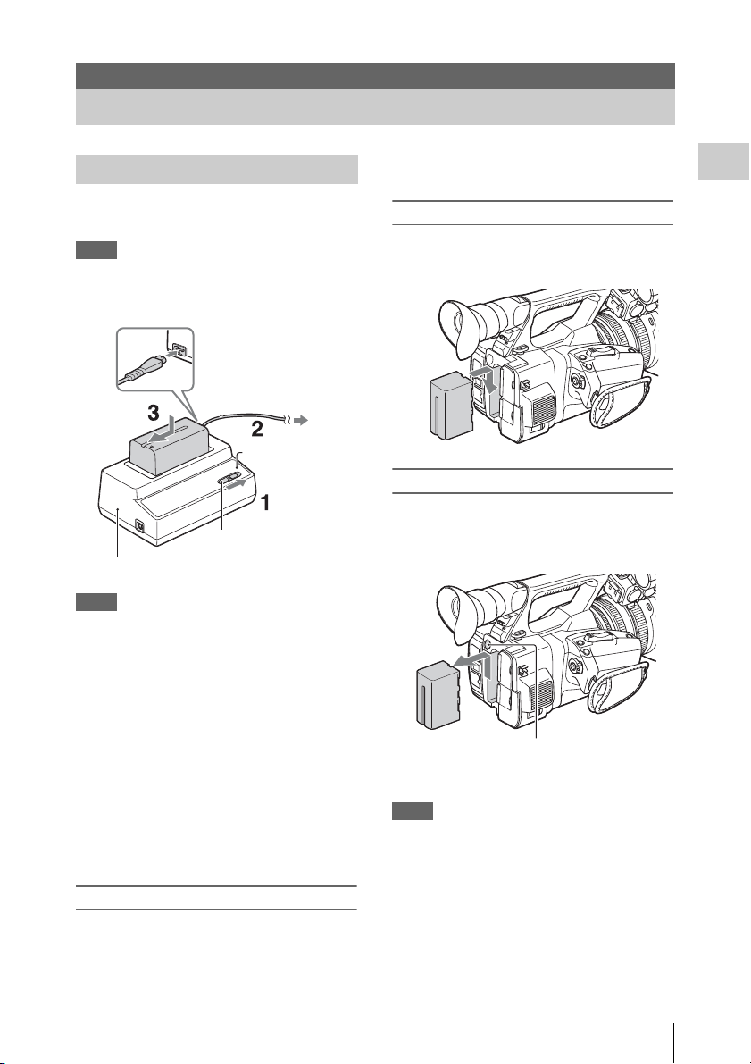
Charging the battery pack
You can charge the “InfoLITHIUM” battery pack
(L series) with the supplied Charger.
Notes
• You can use a large capacity battery pack, NP-F970
(supplied), with your camcorder. You cannot use NPF570/F770 (sold separately).
Power cord
(mains lead)
To the wall outlet
(wall socket)
Charge lamp
Mode switch
Charger AC-VL1
Notes
• You cannot use the AC-VL1 to connect the camcorder
to an outside power source. When you connect the
camcorder to a wall outlet (wall socket), use the
supplied AC Adaptor.
Remove the battery pack from the Charger when
the charge is completed.
Attaching the battery pack
Press the battery pack against the back of your
camcorder and slide it down.
Removing the battery pack
Slide the POWER switch to OFF. Push the BATT
RELEASE (battery release) button and remove
the battery pack.
Preparations
1 Set the mode switch to CHARGE.
2 Connect the power cord (mains lead) to
the Charger and the wall outlet (wall
socket).
3 Place the battery pack in the slot of the
Charger, press it down, and slide it in
the direction of the arrow.
The charge lamp turns on and charging starts.
After charging the battery
The charge lamp turns off (normal charge). If you
continue charging 1 more hour after the charge
lamp turns off, you can use the battery a little
longer (full charge).
BATT RELEASE
(battery release) button
Notes
• Settings of the menu or settings adjusted using the
AUTO/MANUAL switch can be saved when the
POWER switch is set to OFF. Remov e the battery pack
after the display on the LCD/viewfinder screen has
completely disappeared. Otherwise, changed settings
may not be saved.
• If you remove the battery p ack or AC Adaptor with the
POWER switch ON, you cannot turn the camcorder on
even though you attach the battery pack or AC Adaptor
again.
Slide the POWER switch to OFF temporarily, then to
ON.
Power Supply
21
Page 22
Storing the battery pack
If the battery pack is not in use for a while, run
down the battery and store it. See page 55 for
details on storage of the battery pack.
Charging time
Preparations
Approximate time (minute) required when you
charge a fully discharged battery pack.
Battery pack
NP-F970 365 425
Notes
• You cannot use the NP-F570/NP-F770 battery pack
with your camcorder.
Normal charge
time
Full charge time
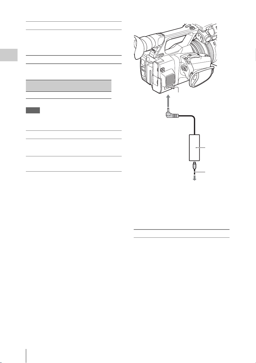
DC IN
connector
On the battery pack
• Before changing the battery pack, slide the POWER
switch to OFF.
Using a wall outlet (wall socket) as a
power source
You can use the AC Adaptor to obtain AC power.
AC
Adaptor
(ACNB12A)
To the wall outlet
(wall socket)
Power
cord
(mains
lead)
1. Connect the power cord (mains lead) to the
AC Adaptor.
2. Connect the AC Adaptor to the DC IN
connector of the camcorder.
3. Connect the power cord (mains lead) to the
wall outlet (wall socket).
On the AC Adaptor
• Use the nearby wall outlet (wall socket) when
using the AC Adaptor. Disconnect the AC
Adaptor from the wall outlet (wall socket)
immediately if any malfunction occurs while
using your camcorder.
• Do not use the AC Adaptor placed in a narrow
space, such as between a wall and furniture.
• Do not short-circuit the plug of the AC Adaptor
with any metallic objects. This may cause a
malfunction.
• Even if your camcorder is turned off, AC power
(house current) is still supplied to it while
connected to t he wall outlet (wall sock et) via the
AC Adaptor.
• You cannot charge the camcorder by
connecting it to the AC Adaptor.
22
Power Supply
Page 23

Setting the Clock Attaching Devices
When you turn the camcorder on for the first time
after purchasing or the backup battery has
completely discharged, the Initial Setting display
appears on the viewfinder screen and LCD
screen. Set the date and time of the built-in clock,
using this display.
Time Zone
The value shows the time difference from UTC
(Coordinated Universal Time).
Change the setting if needed.
Setting the time and date
Clock starts after you turn the SEL/SET dial
(page 16) to select the items or value, then press
the SEL/SET dial to set them.
After the setting display disappears, “Clock Set”
(page 47) in the System menu can be used to set
“Time Zone” and date/time.
Notes
• If the clock setting is cleared because the backup
battery fully discharged when no power was supplied
(no battery pack and no DC IN connection), the Initial
Setting display will be displayed when you next turn
the camcorder on.
• While the Initial Setting display is shown, no other
operation, except turning the power off, is permitted
until you finish the setting for this display.
Attaching the lens hood with lens cover
PUSH (lens hood release) button
Align the marks on the lens hood to those on
the camcorder, and turn the lens hood in the
direction of the arrow 2 until it is locked.
Opening or closing the shutter of the lens
hood with lens cover
Move the lens cover lever to OPEN to open the
lens cover, and move the lever to CLOSE to close
the lens cover.
Preparations
Removing the lens hood with lens cover
Turn the lens hood in the opposite direction to the
arrow 2 in the illustration while pressing the
PUSH (lens hood release) button.
Notes
• Remove the lens hood with lens cover when you
attach/detach a 72mm polarized filter or protective
filter.
Setting the Clock / Attaching Devices
23
Page 24

Adjusting the LCD screen and viewfinder
LCD screen
Open the LCD screen 180 degrees (1), then
Preparations
rotate it to the best angle to record or play back
(2).
1Open 180 degrees.
290 degrees
(max.)
2180 degrees
(max.)
• Images are displayed as mirror images on the
LCD screen, but are recorded as normal images.
• You can switch the brightness of the backlight
of the LCD screen with “LCD Backlight” of
“LCD Setting” in the LCD/VF menu (page 45).
You can switch the brightness of the viewfinder
backlight with “VF Backlight” of “VF Setting” in
the LCD/VF menu (page 45).
Viewfinder
Viewfinder lens
adjustment lever
Move it until the picture
becomes clear.
Notes
• You may see primary colors shimmering in the
viewfinder when you move your line of sight. This is
not a malfunction. The shimmering colors will not be
recorded on the recording media.
Attaching Devices
24
Page 25
Using XQD Memory Cards
This camcorder records audio and video on XQD
memory cards inserted in the card slots.
Notes
• Data integrity is not guaranteed if the power is turned
off or a memory card is removed while it is being
accessed. Data on the card may be destroyed. Be sure
that its access lamp is lit in green or off when you turn
off the power or remove a memory card.
• An XQD memory card removed from the camcorder
after recording ended may be hot. This is not a
malfunction.
Preparations
About XQD memory cards
Use the following Sony XQD memory cards.
XQD memory card S series
XQD memory card H series
XQD memory card N series
Operations are not guaranteed with other memory
cards.
For details on using XQD memory cards and usagerelated precautions, refer to the instruction manual
for the XQD memory card.
Inserting an XQD memory card
1 Open the cover of the card slot block.
2 Insert the XQD memory card until it
clicks into place with the XQD label
facing to the left.
The access lamp (page 15) lights in red then
changes to green once the memory card is
ready for use.
3 Close the cover.
Notes
• If you insert a memory card into the slot in the wrong
direction, the memory card, the memory card slot, or
image data may be damaged.
Removing an XQD memory card
Open the cover of the card slot block,
remove the XQD memory card by pressing
the XQD memory card once lightly.
Selecting the memory card slot to be used for recording
Press the A or B button of the memory card slot
where the memory card you want to record on is
inserted. The lamp of the selected slot lights up in
green.
Memory card slot A button
Memory card slot B button
Notes
• You can only select a slot that already has a memory
card inserted.
• While movies are being recorded on the memory card,
you cannot switch the slot even if you press the
memory card slot A/B buttons.
• When only one slot has a memory card inserted,
the slot that has the memory card is selected
automatically.
• If the memory card is fully recorded during
recording, the camcorder continues recording
automatically on the memory card inserted in
the other slot.
Using XQD Memory Cards
25
Page 26

Formatting an XQD memory card
If an XQD memory card is not formatted, or was
formatted with another system, the message
“Media Needs to be Formatted” is displayed on
the LCD/viewfinder screen.
Format the card as follows.
Preparations
Using “Format Media” (page 46) in the
Media menu, specify “Media(A)” (slot A) or
“Media(B)” (slot B) then select “Execute.”
On a confirmation message, select
“Execute” again.
The in-progress message and status bar are
displayed, and the access lamp lights in red.
When formatting is complete, a completion
message is displayed. Press the SEL/SET dial to
hide the message.
If formatting fails
A write-protected XQD memory card or memory
card that cannot be used with this camcorder will
not be formatted.
As a warning message is displayed, replace the
card with an appropriate XQD memory card,
according to the instructions in the message.
Notes
• All the data, including recorded pictures and setup
files, are erased when a memory card is formatted.
Replacing an XQD memory card
• If the available time on two cards in total
becomes less than 5 minutes, the warning
message “Media Near Full” is displayed, the
recording lamp flashes, and a beep sound is
output to the headphones to warn you. Replace
the cards with those that have sufficient space.
• If you continue recording until the total
remaining time reaches zero, the message
changes to “Media Full,” and recording stops.
Notes
• Up to approximately 9,999 clips can be recorded on
one XQD memory card.
If the number of recorded clips reaches the limit, the
remaining time indication becomes “0,” and the
message “Media Full” is displayed.
Checking the remaining time available for recording
While recording (or standing by to record), you
can check the remaining space for the XQD
memory cards loaded in the card slots on the A/B
slot media status/remaining space indication of
the LCD screen/viewfinder screen (page 19).
The available time for recording with the current
video format (recording bit rate) is calculated
according to the remaining space of each card and
displayed in time units of minutes.
Notes
• A icon appears if the memory card is writeprotected.
Using XQD Memory Cards
26
Page 27

Recording
Basic Operation Procedure
Basic recording can be performed with the
following procedures.
1 Make sure that the necessary devices
are attached to the camcorder and
power is supplied to them.
2 Load the memory card(s).
If you load two cards, recording is continued
by automatically switching to the second
card when the first card becomes full.
3 Open the shutter of the lens hood with
lens cover.
4 Slide the POWER switch to ON while
pressing the green button.
The recording screen is displayed on the
LCD/viewfinder screen.
5 Press the record button (page 14).
The recording lamp lights and recording
begins.
6 To stop recording, press the record
button again.
Recording stops and the camcorder enters
STBY (recording standby) mode.
Adjusting the zoom
To use the power zoom lever
Move the power zoom lever D slightly for a
slower zoom. Move it further for a faster zoom.
Wide view: (Wide angle)
Close view: (Telephoto)
• The minimum distance required between your
camcorder and the subject for focus is about
1 cm (about 13/32 in.) for wide angle and about
80 cm (about 2 5/8 feet) for telephoto.
• The focus may not be adjusted at certain zoom
positions if the subject is within 80 cm (about
2 5/8 feet) from your camcorder.
• Be sure to keep your finger on the power zoom
lever D. If you move your finger off the power
zoom lever D, the operation sound of the
power zoom lever D may also be recorded.
To use the handle zoom
1. Set the handle zoom switch B to VAR or
FIX.
• When you set the handle zoom switch B
to VAR, you can zoom in or out at variable
speed.
• When you set the handle zoom switch B
to FIX, you can zoom in or out at fixed
speed, as set in “Setting” in “Handle
Zoom” of the Camera menu (page 41).
2. Press the handle zoom lever A to zoom in or
out.
Notes
• You cannot use the handle zoom lever A when the
handle zoom switch B is set to OFF.
• You cannot change the zoom speed of the power zoom
lever D with the handle zoom switch
Using the zoom ring
You can zoom at the desired speed by turning the
zoom ring C. Fine adjustment is also possible.
B.
Recording
Basic Operation Procedure
27
Page 28
Notes
• Turn the zoom ring C at a moderate speed. If you turn
it too fast, the zoom speed may lag behind the zoom
ring rotation speed, or the operation sound of the zoom
may also be recorded.
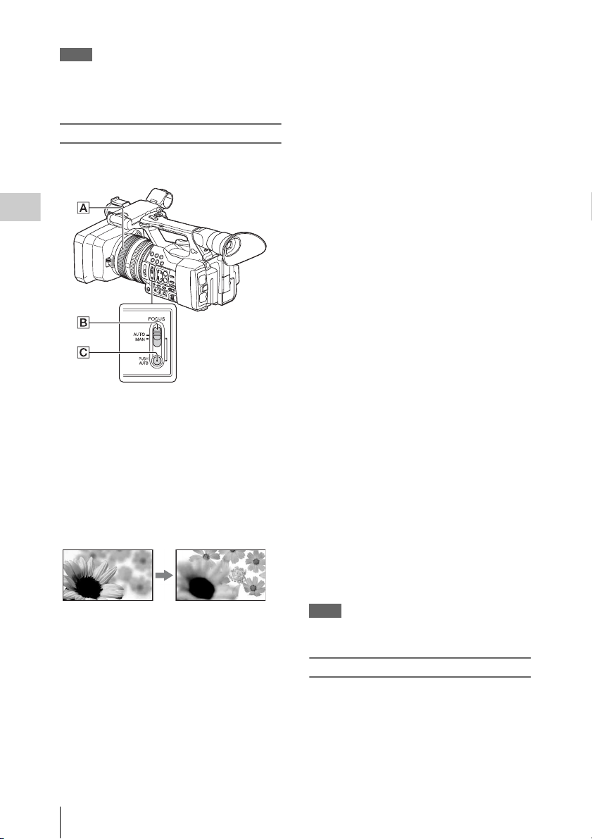
Adjusting the focus manually
Recording
You can adjust the focus manually for different
recording conditions.
Use this function in the following cases.
—To record a subject behind a window
covered with raindrops.
—To record horizontal stripes.
—To record a subject with little contrast
between the subject and its background.
—When you want to focus on a subject in the
background.
—To record a stationary subject using a
tripod.
For focusing manually
• It is easier to focus on the subject when you use
the zoom function. Move the power zoom lever
towards T (tel ephoto) and adjust the foc us, then,
towards W (wide angle) to adjust the zoom for
recording.
• When you want to record a close-up image of a
subject, move the power zoom lever towards W
(wide angle) to fully magnify the image, then
adjust the focus.
To restore automatic adjustment
Set the FOCUS switch B to AUTO.
The focus mode indication changes to “AF” and
the automatic focus adjustment is restored.
To use automatic focus temporarily
(Push auto focus)
Record the subject while pressing and holding the
PUSH AUTO button C.
If you release the button, the setting returns to
manual focusing.
Use this function to shift the focus on one subject
to another. The scenes will shift smoothly.
• The focal distance information (for when it is
dark and hard to adjust the focus) appears for
about 3 seconds in the following cases. (It will
not be displayed correctly if you are using a
conversion lens (sold separately)).
—When you rotate the focus ring while “MF”
is displayed on the screen
To use the expanded focus (Expanded focus)
In the default setting, “Focus Magnifier” is
assigned to the ASSIGN 7 button (page 35).
Press the ASSIGN 7 button.
The focus mag nifier screen appears and the center
of the screen is magnified by about 2.0 times. It
will be easier to confirm the focus setting during
manual focusing. The screen returns to the
original size when you press the button again.
Notes
• Even though the image appears expanded on the
screen, the recorded image is not expanded.
1 During recording or standby, set the
FOCUS switch B to MAN.
The focus mode indication changes to “MF.”
2 Rotate the focus ring A and adjust the
focus.
Basic Operation Procedure
28
Playing a recorded clip
You can play the recorded clip while the
camcorder is in standby mode.
1 Insert the XQD memory card.
2 Press the PLAY/PAUSE button of the
playback control buttons.
Page 29

3 Search for the desired clip by pressing
PREV or NEXT button.
4 Press the PLAY/PAUSE button.
The playback image appears on the
viewfinder.
Playback operation is performed as follows.
PLAY/PAUSE button: Pauses playback. To
resume playback, press this button again.
F FWD button/F REV button: Plays fast. To
return to normal playback, press the PLAY/
PAUSE button.
STOP button: Stops playback or recording.
Monitoring audio
In normal playback mode, you can monitor the
recorded audio signals through the connected
headphones.
You can select audio channel to be monitored and
adjust the sound volume with “Audio Output”
(page 44) in the Audio menu.
Cueing Up
To start playback from the top of the clip
Press the PREV button or NEXT button of the
playback control buttons (page 16). You can cue
to the top of a desired clip by pressing either
button repeatedly.
Clip (recording data)
When you stop recording, video, audio and
subsidiary data from the start to end of the
recording are recorded as a single clip on an
XQD memory card.
Maximum duration of a clip
The maximum clip length is 13 hours.
The maximum continuous recording time for a
movie is approximately 13 hours. If recording
time reaches approximately 13 hours, the
recording will stop.
Recording
Switching the XQD memory cards
When two memory cards are loaded, press the
select button (page 15) to switch memory cards.
Notes
• You cannot switch XQD memory cards during
playback.
Continuous playback of cards in slots A and B is not
possible.
Basic Operation Procedure
29
Page 30
Changing Basic Settings
You can make changes to the settings based on
the intended usage of the recorded video or
recording conditions.
Recording format
Selectable format depends on the setting of the
region where the camcorder is used (Country).
Recording
To change the format, use “Video Format” in
“Rec Format” (page 46) of the System menu.
Adjusting the image brightness
1. During recording or standby, set the AUTO/
MANUAL switch H to MANUAL.
2. When the iris is automatically adjusted, press
the IRIS button E.
The iris value appears. When the iris value is
automatically adjusted, “A.Iris” is displayed.
3. Adjust the iris with the iris ring A.
• The F value becomes close to F3.4 as the zoom
position changes from W to T even when you
open the aperture by setting the F value lower
than F3.4, such as F1.6.
• The range of focus, an important effect of the
aperture, is called the depth of field. The depth
of field gets shallower as the aperture is opened,
and deeper as the aperture is closed. Use the
aperture creatively to obtain the desired effect
in your photography.
• This is handy for making the background
blurred or sharp.
To adjust the iris automatically
Press the IRIS button E, or set the AUTO/
MANUAL switch H to AUTO.
“A.Iris” is displayed next to the iris value.
Notes
• When you set the AUTO/MANUAL switch H to
AUTO, other manually adjusted items (gain, shutter
speed, white balance) also become automatic.
You can adjust the image brightness by adjusting
the iris, gain or shutter speed, or by reducing the
light volume with the ND FILTER switch B.
Adjusting the iris
You can manually adjust the iris to control the
volume of the light entering the lens. By adjusting
the iris, you can change or close ( ) the
aperture of the lens, which is expressed as an F
value between F1.6 and F11. The volume of the
light increases the more that you open the
aperture (decreasing F value). The volume of the
light decreases the more that you close the
aperture (increasing F value). The current F value
appears on the screen.
Changing Basic Settings
30
Adjusting the gain
You can adjust the gain manually when you do
not want to use the AGC (automatic gain control).
1. During recording or standby, set the AUTO/
MANUAL switch H to MANUAL.
2. When the gain is automatically adjusted,
press the GAIN button C.
“AGC” is displayed.
3. Set the gain switch F to H, M or L. The gain
value set for the selected gain switch position
appears on the screen. You can set the gain
value for H/M/L from “Gain” of the Camera
menu (page 41).
To adjust the gain automatically
Press the GAIN button C, or set the AUTO/
MANUAL switch H to AUTO.
The gain value disappears. “AGC” is displayed
next to the gain value.
Page 31

Notes
• When you set AUTO/MANUAL switch H to AUTO,
other manually adjusted items (iris, shutter speed,
white balance) also become automatic.
Adjusting the shutter speed
You can manually adjust and fix the shutter
speed. You can make a moving subject look still
or emphasize the movement of a moving subject
by adjusting the shutter speed.
1. During recording or standby, set the AUTO/
MANUAL switch H to MANUAL.
2. Press the SHUTTER SPEED button D to
display the Shutter Value.
3. Change the Shutter Value displayed on the
screen by turning the SEL/SET dial G.
You can adjust the shutter speed in a range of
1/4 second through 1/9000 second (NTSC
Area) and 1/3 second through 1/9000 second
(PAL Area).
The set Shutter Value appears on the screen.
For example, “1/100” appears on the screen
when you set the shutter speed to 1/100
second. The larger the denominator value on
the screen, the faster the shutter speed.
4. Press the SEL/SET dial G to lock the
Shutter Value.
To readjust the shutter speed, do steps 2 to 4.
• The shutter speed range that can be set depends
on the frame rate.
• It is difficult to focus automatically at a lower
shutter speed. Manual focusing with your
camcorder attached to a tripod is recommended.
• When recording under fluorescent lamps,
sodium lamps, or mercury lamps, the picture
may flicker or change colors, or may have
horizontal bands of noise. You may be able to
improve the situation by adjusting the shutter
speed.
To adjust the shutter speed automatically
Press the SHUTTER SPEED button D twice, or
set the AUTO/MANUAL switch H to AUTO.
The Shutter Value disappears. When the shutter
speed is automatically adjusted, “A.SHT” is
displayed.
Notes
• When you set the AUTO/MANUAL switch H to
AUTO, other manually adjusted items (iris, gain, white
balance) also become automatic.
Adjusting the volume of light
(ND filter)
You can record the subject clearly by using the
ND FILTER switch B when the recording
environment is too bright.
OFF: ND filter is not used.
1: Reduce the amount of light to 1/4.
2: Reduce the amount of light to 1/16.
3: Reduce the amount of light to 1/64.
While the iris is automatically adjusted, the
“Video Level Warning” is displayed.
If ND OFF flashes, set the ND FILTER switch to
OFF. The ND filter icon will disappear from the
screen.
Notes
• If you change the ND FILTER switch B during
recording, the movie and sound may be distorted.
• When adjusting the iris manually, the “Video Level
Warning” is not displayed even if the light volume
should be adjusted with the ND FILTER switch.
While recording a bright subject, diffraction may
occur if you close the aperture further down,
resulting in a fuzzy focus (this is a common
phenomenon with video cameras). The ND
FILTER switch B suppresses this phenomenon
and gives better recording results.
Adjusting to natural color (White balance)
Recording
Changing Basic Settings
31
Page 32

You can adjust and fix the white balance
according to the lighting conditions of recording
environment.
You can store white balance values in memory A
( A) and memory B ( B), respectively.
Unless a white balance is readjusted, values will
remain even after the power has been turned off.
When you select PRESET, “Outdoor,” “Indoor”
or “Color Temp.” is set, according to which one
you previously selected with “Preset White” in
“White” of the Paint menu.
1 During recording or standby, set the
Recording
AUTO/MANUAL switch D to
MANUAL.
2 Press the WHT BAL button A.
3 Set the white balance memory switch
B to any one of PRESET/A/B.
Select A or B for recording with the white
balance setting stored in memory A or B.
Indicator Shooting conditions
A
(Memory A)
B
(Memory B)
Outdoor
n
Indoor
Color temperature
(“Color Temp.”)
• White balance values adjusted
for light sources can be stored in
memory A and memory B.
Follow the steps in “To save the
adjusted white balance value in
memory A or B” (page 32).
• Recording neon signs or
fireworks
• Recording sunset/sunrise, just
after sunset or just before
sunrise
• Under daylight color fluorescent
lamps
• Under the lighting conditions
that change in many ways, such
as a party hall
• Under strong light, such as in a
photography studio
• Under sodium lamps or mercury
lamps
• Color temperature can be set
between 2300K and 15000K
(the default setting is 3200K).
• You can change the color temperature. Set
“Color Temp.” in “Preset White” in “White” of
the Paint menu, and the white balance memory
switch B to PRESET, then press the (one
push) button C. Turn the SEL/SET dial E
until the desired temperature appears on the
screen, then press the dial to set the temperature.
You can also set the color temperature by
pressing the WHT BAL button A + (one
push) button C.
To save the adjusted white balance value in
memory A or B
1. Set the white balance memory switch to A
(A) or B (B) in step 3 of “Adjusting to
natural color (White balance).”
2. Capture a white subject, such as white paper,
full-screen in the same lighting condition as
the one in which the subject is.
3. Press the (one push) button C.
A or B starts flashing rapidly. It will
stay on when the white balance adjustment is
completed and the adjusted value is stored in
A or B.
Notes
• It may take a long time to adjust the white balance,
depending on the recording conditions. If you want to
perform a different operation before completing the
adjustment, set the white balance memory s witch B to
another position to temporarily suspend white balance
adjustment.
To adjust the white balance automatically
Press the WHT BAL button A or set the AUTO/
MANUAL switch D to AUTO.
Notes
• When you set the AUTO/MANUAL switch D to
AUTO, other manually adjusted items (iris, gain, and
shutter speed) also become automatic.
Changing Basic Settings
32
Page 33

Audio setup
The following connectors, switches and dials
allow you to set the sound to be recorded.
External audio input jacks and switches
INPUT 1 jack B
INPUT 2 jack A
INPUT 1 switch C
INPUT 2 switch D
Audio source switches
CH1 (INT MIC/INPUT 1/INPUT 2) switch E
CH2 (INT MIC/INPUT 1/INPUT 2) switch J
Audio level controls
CH1 (AUTO/MAN) switch
CH2 (AUTO/MAN) switch I
AUDIO LEVEL (CH1) dial G
AUDIO LEVEL (CH2) dial H
Using the internal microphone
The sound will be recorded in stereo when using
the internal microphone.
Set the CH1 (INT MIC/INPUT 1/INPUT 2)
and CH2 (INT MIC/INPUT 1/INPUT 2)
switches to INT MIC.
F
• If the recording level is low, set “INT MIC
Sensitivity” in “Audio Input” of the Audio
menu to “High” (page 44).
• To reduce wind roar, set “INT MIC Wind
Filter” in “Audio Input” of the Audio menu to
“On” (page 44).
Recording sound from an external audio
device
To use an external audio device, or a microphone
(sold separately), change the settings as follows.
1. Select the input source.
Set the INPUT 1/INPUT 2 switches
according to the devices connected to the
INPUT 1/INPUT 2 jacks.
Audio devices Switch
External audio device (mixer,
etc.)
Dynamic microphones or
microphones with a built-in
battery
+48V powering (Phantom
powering)
microphone
• If you connect a device that does not
support +48V phanto m power, malfunction
may result from setting this switch to
MIC+48V. Check before connecting the
device.
• When there is no audio device connected to
an INPUT jack, set the INPUT switch of
that jack to LINE to prevent noise.
position
LINE
MIC
MIC+48V
2. Set the input level of the microphone.
• Set the input level of the microphone by
“INPUT1 Reference/INPUT 2 Reference” in
“Audio Input” of the Audio menu
(page 44). Adjust according to the
sensitivity of the microphone.
3. Select the channel you want to record.
Using the CH1/CH2 switches, select the
source to be recorded on each channel.
Recording
Changing Basic Settings
33
Page 34

Recording
When the CH1 switch is set to INT MIC
Input source and recorded
channel
CH2
switch
setting
INT MIC (L)
INT MIC (R)
INT MIC (mono)
INPUT 1
CH1
CH2
CH1
CH2
2. During recording or standby, turn the
AUDIO LEVEL dial (G or H) of the
channel to be adjusted.
To restore automatic adjustment
Set the AUTO/MAN switch (F or I) of the
manually adjusted channel to AUTO.
Setting the headphone sound
INT MIC (mono)
INPUT 2
CH1
CH2
When the CH1 switch is set to INPUT 1
Input source and recorded
channel
CH2
switch
setting
INPUT 1
INT MIC (mono)
INPUT 1
INPUT 1
INPUT 2
CH1
CH2
CH1
CH2
CH1
CH2
• When the CH1 switch is set to INPUT 2, the
INPUT 2 source is recorded to CH1.
• When you use a stereo microphone (2 XLR
plugs), connect the L (left) channel plug to the
INPUT 1 jack, and the R (right) channel plug to
the INPUT 2 jack. Set the CH1 switch to
INPUT 1, and the CH2 switch to INPUT 2.
You can select the channel by setting the switch
to CH1 or CH2, to output from the headphone.
See “Headphone Out” in “Audio Output” of
Audio menu on the sound at STEREO MIX
(page 44).
Adjusting the volume
When both the CH1/CH2 switches are set to INT
MIC, left and ri ght channels are linked to the CH 1
switch and dial.
1. Set the AUTO/MAN switch (F or I) of
the channel to be adjusted to MAN.
appears on the LCD screen.
Changing Basic Settings
34
Page 35

Useful Functions
Assignable buttons
The camcorder has seven assignable buttons
(pages 12, 13) to which you can assign various
functions for convenience.
Changing functions
Use “Assignable Button” (page 46) in the System
menu.
The assigned functions can be viewed on the
assignable button status screen (page 17).
Default assigned functions
Button 1 Off
Button 2 Off
Button 3 Off
Button 4 Zebra
Button 5 Peaking
Button 6 Thumbnail
Button 7 Focus Magnifier
Assignable functions
•Off
•Marker (page 45)
•Zebra (page 45)
• Peaking (page 45)
• Focus Magnifier (page 28)
• Auto Exposure Level (page 41)
• SteadyShot (page 41)
• Color Bars (page 41)
• Rec Lamp[F] (page 46)
• Rec Lamp[R] (page 46)
• Thumbnail (page 47)
Recording
Useful Functions
35
Page 36

Thumbnail Screens
Thumbnail Screens
When you press the THUMBNAIL button (page 16), clips recorded on the XQD memory card are
displayed as thumbnails on the screen.
You can start playback from the clip selected on the thumbnail screen. The playback picture can be seen
on the LCD/viewfinder screen and external monitors.
Press the THUMBNAIL button to exit the thumbnail screen and return to the recording screen.
Configuration of the screen
Information for the clip selected with the cursor are displayed at the bottom of the screen.
The icon of the current XQD memory card is highlighted, shading the nonselected
one. (If the card is write-protected, a lock icon is displayed to the right.)
Thumbnail Screens
Cursor
(yellow)
Current clip No./ Total number of clips
1. Thumbnail
The thumbnail image for each clip is an index
frame from the clip. When recording, the first
frame of a clip is automatically set as the index
frame.
Below each thumbnail, the clip/frame
information is displayed. You can change the
displayed item on “Thumbnail Caption” in
“Customize View” (page 37) of the thumbnail
menu.
2. Clip name
The clip name of the selected clip is displayed.
Thumbnail Screens
36
3. Recording video format
The file format of the selected clip is displayed.
4. Duration of the clip
5. Creation date and time
Page 37

Playing Clips
Clip Operations
Playing the selected and subsequent clips in sequence
1 Turn the SEL/SET dial (page 16) to
move the cursor to the thumbnail image
of the clip with which you wish to start
playback.
2 Press the SEL/SET dial.
Playback starts from the beginning of the
selected clip.
Notes
• The playback picture may be momentarily distorted or
frozen between clips. You cannot operate the
camcorder during this condition.
• When you select a clip on the thumbnail screen and
start playback, the playback picture at the beginning of
the clip may be distorted. To start playback without
distortion, pause playback once after starting it, press
the PREV button of the playback control buttons to
return to the top of the clip, then restart playback.
On the thumbnail screen, you can operate the
clips or confirm the subsidiary data for clips using
the thumbnail menu. The thumbnail menu
appears when you press the OPTION button
(page 16) on the thumbnail screen.
Operations of the thumbnail menu
Turn the SEL/SET dial (page 16) to select a menu
item, then press the SEL/SET dial.
Pressing the CANCEL/BACK button (page 16)
restores to the previous condition.
Pressing the OPTION button while the thumbnail
menu is displayed turns the thumbnail menu off.
Notes
• When the XQD memory card is write-protected, some
operations are unavailable.
• There may be items t hat cannot be selected, depending
on the status when the menu is displayed.
Clip operation menu
Display Clip Properties
Displays the detailed information of a clip screen
(page 38).
Delete Clip
Select Clip: Deletes the selected clip (page 39).
Customize View
Thumbnail Caption: Changes the items that are
displayed under the thumbnail image.
(page 39)
Thumbnail Screens
Playing Clips / Clip Operations
37
Page 38

Displaying the detailed information of a clip
Select “Display Clip Properties” from the thumbnail menu.
Thumbnail Screens
1. Image of the current clip
2. Timecode
Duration: Duration of the clip
3. Date of recording/modifying
4. Currently selected memory card
5. Media protect icon
6. Clip number/Total number of clips
7. Battery icon
8. Clip name
9. Clip title 1/2
10. Recording format
Video Codec: Video codec
Size: Picture size
FPS: Frame rate/bit-rate
Audio Codec: Audio codec
Ch/Bit: Number of the recorded audio channel/
audio recording bit
11. Special recording information
12. Recording device name
38
Clip Operations
Page 39

Deleting clips
You can delete clips from the XQD memory card.
Select “Select Clip” from “Delete Clip” on the
thumbnail menu.
You can select multiple clips to be deleted. Press
the OPTION button (page 16) after selecting the
clip to be deleted.
Changing information on the thumbnail screen
You can change information of the clip/frame t hat
is displayed under thumbnail.
Select the displayed item from “Thumbnail
Caption” in “Customize View” on the thumbnail
menu.
Date Time: Creation date or modified time
Time Code: Timecode
Duration: Duration
Sequential Number: Thumbnail number
Thumbnail Screens
Clip Operations
39
Page 40

Settings
Setup Menu Operations
The Setup menu allowing you to perform various
settings that are needed for recording and playing,
appears on the LCD/viewfinder screen by
pressing the MENU button. (You can display the
Setup menu on the external video monitor.)
Menu controls
MENU button (page 16)
To turn the menu mode to use the setup menus on/
off.
SEL/SET dial (page 16)
When you turn the dial, the cursor moves up or
down, permitting you to select menu items or
setting values.
Press the SEL/SET dial to select the highlighted
item.
CANCEL/BACK button (page 16)
To return to the previous menu. An uncompleted
Settings
change is canceled.
V/v/B/b SET button
When you press the V/v/B/b buttons, the cursor
moves in the corresponding direction, permitting
you to select menu items or setting values.
Press the SET button to enter the highlighted
item.
Notes
• In Focus Magnifier mode (page 28), the setup menu
cannot be used.
• When you select an item that you must confirm
before execution, the menu display temporarily
disappears, and a confirmation message is
displayed. Follow the instructions of the
message, and specify whether to execute or
cancel.
Setting the Setup menus
Turn the SEL/SET dial to set the cursor to the
item of the menu you wish to set, then press the
SEL/SET dial to select that item.
• The menu item selection area can show 9 lines
at maximum. When all the selectable items
cannot be displayed at one time, you can scroll
the display up or down by moving the cursor.
• For items having a wide range of available
values (example: –99 to +99), the available
value area is not displayed. The current setting
is highlighted instead, indicating that the setting
is ready for change.
• When you select “Execute” for an execution
item, the corresponding function is executed.
Setup Menu Operations
40
Page 41

Setup Menu List
The functions and available settings of menus are listed below.
The default settings set at the factory are shown in bold face (example: 18dB).
Camera menu
Camera
Menu items Sub items and setting values Contents
Gain
Setting for the gain
Auto Exposure
Setting for the total
level control
system
Color Bars
Setting for the
color bars
Flicker Reduce
Setting for the
flicker correction
SteadyShot
Setting for the
SteadyShot
function
Handle Zoom
Setting for the
handle zoom speed
Gain<H>
0dB / 3dB / 6dB / 9dB / 12dB /
15dB / 18dB / 21dB
Gain<M>
0dB / 3dB / 6dB / 9dB / 12dB /
15dB / 18dB / 21dB
Gain<L>
0dB / 3dB / 6dB / 9dB / 12dB /
15dB / 18dB / 21dB
Level
–2.0 / –1.75 / –1.5 / –1.25 /
–1.0 / –0.75 / –0.5 / –0.25 / 0 /
+0.25 / +0.5 / +0.75 / +1.0 /
+1.25 / +1.5 / +1.75 / +2.0
Speed
–99 to +99 (±0)
AGC Limit
3dB / 6dB / 9dB / 12dB /
15dB / 18dB / 21dB / 24dB
A.SHT Limit
Off / 1/100 / 1/150 / 1/200 /
1/250
Setting
On / Off
Type
ARIB / SMPTE / 75% / 100%
Mode
Auto / On / Off
Frequency
50Hz / 60Hz
Setting
On / Off
SteadyShot Type
Hard / Standard / Soft / Wide
Conversion
Setting
1 to 8 (3)
Sets the preset value <H> of the gain.
Sets the preset value <M> of the gain.
Sets the preset value <L> of the gain.
Sets the TLCS level.
Sets the control speed of the TLCS.
Sets the maximum gain of the AGC function.
Sets the fastest shutter speed for the auto shutter function.
Turns the color bars on/off.
Selects the type of color bar.
Sets the flicker correction mode.
Sets the power frequency of lights that cause the flicker.
Turns on/off the SteadyShot function.
Selects the SteadyShot type.
Sets the handle zoom speed.
(This setting is available only when the handle zoom switch is
set to “FIX.”)
Settings
Setup Menu List
41
Page 42

Paint menu
Paint
Menu items Sub items and setting values Contents
White
Setting for white
balance
Offset White
Setting for the
offset white
balance
Settings
Gamma
Adjusting the
gamma
compensation
Detail
Setting for the
detail adjusting
Preset White
Outdoor
/ Indoor / Color Temp.
Color Temp. <Preset>
2300K to 15000K (3200K)
Shockless White
Off / 1 / 2 / 3
ATW Speed
1 / 2 / 3 / 4 / 5
Setting
On / Off
Offset<A>
–99 to +99 (±0)
Offset<B>
–99 to +99 (±0)
Offset<ATW>
–99 to +99 (±0)
Gamma Category
STD / CINE
Gamma Select
When “Gamma Category” is set to
“STD”
STD1 DVW / STD2 ×4.5 /
STD3 ×3.5 / STD4 240M /
STD5 R709 / STD6 ×5.0
When “Gamma Category” is set to
“CINE”
Cinematone1 / Cinematone2
Manual Setting
On / Off
Level
–99 to +99 (±0)
Selects the type to be used as the preset.
Displays and sets the color temperature of white balance that
is stored in the white memory.
Sets the speed of change in white balance when the white
balance mode is switched.
Off: Changes instantly.
1 to 3: Select a larger number to change the white balance
more slowly through interpolation.
Sets the reaction speed when in ATW mode.
1: Fastest reaction speed
Turns on/off “Offset White” that is for the auto white balance
(one push) and ATW function.
Adjusts the volume of the offset white for the white memory
(A).
Adjusts the volume of the offset white for the white memory
(B).
Adjusts the volume of the offset white for the ATW.
Select from among “STD” (standard gamma), “CINE.”
Selects the gamma table that is used for the gamma
compensation.
Turns the detail adjusting function on/off.
Adjusts the detail level.
Setup Menu List
42
Page 43

Paint
Menu items Sub items and setting values Contents
Skin Detail
Adjusting the skin
detail
compensation
Matrix
Setting for the
Matrix correction
Setting
On / Off
Area Detection
Execute/Cancel
Area Indication
On / Off
Level
–99 to +99 (±0)
Saturation
–99 to +99 (±0)
Hue
0 to 359
Width
0 to 90 (40)
Setting
On / Off
Preset Matrix
On / Off
Preset Select
Standard / High Saturation /
FL Light / Cinema
User Matrix
On / Off
Level
–99 to +99 (±0)
Phase
–99 to +99 (±0)
Turns the skin detail compensation function on/off.
Detects the color for the skin detail compensation.
Execute: Executes this function.
Turns on/off the function that displays the zebra pattern in the
target area for the skin detail compensation.
Adjusts the skin detail level.
Adjusts the color (saturation) level for the skin detail
compensation.
Adjusts the color hue for the skin detail compensation.
Adjusts the width of the color hue for the skin detail
compensation.
Turns the matrix correction function on/off.
Turns the preset matrix function on/off.
Selects the preset matrix.
Turns the user matrix correction function on/off.
Adjusts the color saturation for the entire picture area.
Adjusts the color phase for the entire picture area.
Settings
Setup Menu List
43
Page 44

Audio menu
Audio
Menu items Sub items and setting values Contents
INPUT1 Reference
–60dB / –50dB / –40dB
INPUT2 Reference
–60dB / –50dB / –40dB
INT MIC Sensitivity
Normal / High
INPUT1 Wind Filter
On / Off
INPUT2 Wind Filter
On / Off
INT MIC Wind Filter
On / Off
Limiter Mode
On / Off
AGC Mode
Mono / Stereo
1KHz Tone
On / Off
Headphone Out
Mono / Stereo
Settings
Audio Input
Setting for audio
inputs
Audio Output
Setting for audio
outputs
Selects the reference input level for when the INPUT1 switch
is set to MIC.
Selects the reference input level for when the INPUT2 switch
is set to MIC.
Selects the sensitivity of the internal microphone.
Turns on/off the wind filter for CH1.
Turns on/off the wind filter for CH2.
Turns on/off the wind filter for the internal stereo
microphone.
Turns the limiter on/off when a loud signal is input while
setting audio input level manually.
Selects the cross-channel linkage of the AGC.
Turn the 1-kHz reference tone signal on/off.
Selects the headphones output, “Mono” or “Stereo.”
Video menu
Video
Menu items Sub items and setting values Contents
Output Format
Setting for the
output format
Setup Menu List
44
HDMI
The setting value changes
depending on the setting of
“Video Format” in “Rec
Format” of the System menu.
The default options are as
follows.
NTSC model:
3840×2160P / 1920×108 0P /
1920×1080i / 720×480P
PAL model:
3840×2160P / 1920×108 0P /
1920×1080i / 720×576P
VIDEO Displays the resolution and scan method. (Display only)
Sets the resolution of the HDMI output.
SET: Execute this function.
Page 45
Video
Menu items Sub items and setting values Contents
Output Display
Setting for the
output signal
HDMI
On / Off
VIDEO
On / Off
Selects whether to add the menu or status on the HDMI
output signal.
Selects whether to add the menu or status on the video output
signal.
LCD/VF menu
LCD/VF
Menu items Sub items and setting values Contents
LCD Setting
Setting for the
LCD screen
VF Setting
Setting for the
viewfinder
Peaking
Setting for the
peaking function
Marker
Setting for the
marker indications
Zebra
Setting for the
zebra pattern
Color
–99 to +99 (±0)
Brightness
–99 to +99 (±0)
LCD Backlight
Normal / Bright
VF Backlight
Normal / Bright
Power Mode
Auto / On
Setting
On / Off
Color
White / Red / Yellow / Blue
Color Peaking Level
0 to 99 (50)
Setting
On / Off
Center Marker
On / Off
Guide Frame
On / Off
Setting
On / Off
Zebra Select
1 / 2 / Both
Zebra1 Level
50% to 107% (70%)
Zebra1 Aperture Level
1% to 20% (10%)
Zebra2 Level
52% to 109% (100%)
Adjusts the color saturation of the LCD screen.
Adjusts the brightness of the LCD screen.
Adjusts the backlight level of the LCD screen.
Adjusts the brightness of pictures on the viewfinder.
Sets the lighting mode according to the LCD screen.
Auto: Lights when the LCD is closed or inverted.
On: Always lights
Turns the peaking function on/off.
Selects the signal color of the color peaking.
Sets the color peaking level.
Turn all marker indications on the viewfinder on/off.
Turns on/off the center marker.
Turns on/off the guide frame display.
Turns the zebra function on/off.
Select the zebra pattern(s) (Zebra 1, Zebra 2, or both of Zebra
1 and Zebra 2) to be displayed.
Sets the display level of zebra 1.
Sets the aperture level of zebra 1.
Sets the display level of zebra 2.
Settings
Setup Menu List
45
Page 46

Media menu
This menu is not available when the media is not loaded.
Media
Menu items Sub items and setting values Contents
Format Media
Formatting a
memory
Media(A)
Execute / Cancel
Media(B)
Execute / Cancel
SD card
Execute / Cancel
System menu
System
Menu items Sub items and setting values Contents
Rec Format
Setting the
recording format
Settings
Assignable
Button
Assigning
functions to the
assignable buttons
Rec Lamp
Setting for the
recording lamp
Video Format
NTSC Area:
3840×2160 59.94P 150
3840×2160 29.97P 100
3840×2160 29.97P 60
3840×2160 23.98P 100
3840×2160 23.98P 60
1920×1080 59.94P 50
1920×1080 29.97P 50
1920×1080 23.98P 50
PAL Ar ea:
3840×2160 50P 150
3840×2160 25P 100
3840×2160 25P 60
1920×1080 50P 50
1920×1080 25P 50
<1> to <7>
Off / Marker / Zebra / Peaking /
Focus Magnifier / Auto
Exposure Level / SteadyShot /
Color Bars / Rec Lamp[F] / Rec
Lamp[R] / Thumbnail
Rec Lamp[F]
On / Off
Rec Lamp[R]
On / Off
Formats the XQD memory card in the slot A.
Execute: Executes format.
Formats the XQD memory card in the slot B.
Execute: Executes format.
Formats the UTILITY SD card
Execute: Executes format.
Sets the recording format.
SET: Execute this function.
Assign a function to the assignable buttons.
Marker: Turns the marker on/off.
Zebra: Turns the zebra function on/off.
Peaking: Turns the peaking function on/off.
Focus Magnifier: Turns the focus magnifier function on/off.
Auto Exposure Level: Turns the auto exposure level function
on/off.
SteadyShot: Turns the SteadyShot function on/off.
Color Bars: Turns the color bars display on/off.
Rec Lamp[F]: Turns the front recording lamp on/off.
Rec Lamp[R]: Turns the rear recording lamp on/off.
Thumbnail: Turns the thumbnail display on/off.
Turns the front recording lamp on/off.
Turns the rear recording lamp on/off.
Setup Menu List
46
Page 47

System
Menu items Sub items and setting values Contents
Language
Setting the
language
Clock Set
Setting the built-in
clock
Country
Setting the region
Hours Meter
Displaying the
hours meter
All Reset
Resetting to the
factory status
Version
Showing the
version of this
camcorder
Select Sets the language to be displayed.
Time Zone
UTC –12:00 Kwajalein to UTC
+14:00
Date Mode
YYMMDD / MMDDYY /
DDMMYY
12H/24H
12H / 24H
Date Sets the current date.
Time Sets the current time.
NTSC/PAL Area Sets the region in which you use the camcorder.
Hours(System) Displays the non-resettable accumulated time of use.
Hours(Reset) Displays the resettable accumulated time of use.
Reset
Execute / Cancel
Reset
Execute / Cancel
Number
Vx.xx
Version Up
Execute / Cancel
SET: Execute this function.
Sets the time-zone difference from UTC in steps of 30
minutes.
Selects the display mode of the date.
YYMMDD: In sequence of year, month, day
MMDDYY: In sequence of month, day, year
DDMMYY: In sequence of day, month, year
Selects the display mode of time.
12H: 12-hour mode
24H: 24-hour mode
SET: Sets the date.
SET: Sets the time.
Execute: Execute this function.
Resets the “Hours(Reset)” value to 0.
Execute: Execute resetting.
Resets th e camcorder to the fact ory status.
Execute: Executes resetting.
Displays the current software version of the camcorder.
Upgrades the camcorder*.
Execute: Executes.
* Upgrade is the function for updating the software of the
camcorder.
Settings
Thumbnail menu
Thumbnail
Menu items Sub items and setting values Contents
Display Clip
Properties
Displaying the
detailed
information screen
of a clip
Delete Clip
Deleting a clip
Execute / Cancel Deletes a selected clip (one or more clips should be selected).
Opens the detailed information screen of the clip.
Execute: Executes this function.
Setup Menu List
47
Page 48

External Devices Connection
Connecting External Monitors and Recording Devices
To display recording/playback pictures on an
external monitor, select the output signal and use
an appropriate cable for the monitor to be
connected.
An output signal from the camcorder can be
recorded when a recording device is connected.
The same status information and menus can be
displayed on the external monitor as those on the
viewfinder screen.
According to the signal fed to the monitor, set
“Output Display” (page 45) in the Video menu to
“On.”
HDMI OUT connector (Type A connector)
Set the on/off setting of the output, and output
format in the Video menu (page 44).
Use a supplied HDMI cable for connection.
When you use a commercially available HDMI
cable, use a high speed HDMI cable.
VIDEO OUT connector (Pin connector)
Use the supplied A/V connecting cable for
connection.
For details, see “Video formats and output
External Devices Connection
signals” (page 59).
Connecting External Monitors and Recording Devices
48
Page 49

Managing Clips with a Computer
Connecting with a USB cable
To use an XQD card reader (sold
separately)
When you connect the MRW-E80 XQD card
reader (sold separately) using a USB cable, the
memory card in the slot is acknowledged as an
extended drive by the computer.
When two memory cards are mounted in this
camcorder, they are acknowledged as two
independent extended drives by the computer.
Notes
• The MRW-E80 does not work on the bus power from
the computer. Supply the operating power
independently.
To use mass storage mode of the
camcorder
1 Set the power switch to ON to turn on
the camcorder.
A message prompting you to confirm that
you wish to enable the USB connection is
displayed on the LCD/viewfinder screen.
Notes
• This message will not be displayed while another
confirmation message or in-progress message
(e.g., for formatting or restoring of an XQD
memory card) is shown on the screen. It appears
when formatting or restoration has completed.
The message is also not displayed while the
screen for the detailed information of a clip is
shown on the screen. It appears when an
operation on the screen for the detailed
information of a clip is completed or you return to
the thumbnail screen.
2 Select “Execute” by turning the SEL/
SET dial.
3 With Windows, check that the memory
card is displayed as a removable disk in
My Computer.
With Macintosh, check that a “NO
NAME” or “Untitled” folder was
created on the desktop. (The Macintosh
folder name can be changed.)
Notes
• The following operations must be avoided when the
access lamp is lit in red.
—Turning the power off or disconnecting the power
cord (mains lead)
—Removing the XQD memory card
—Disconnecting the USB cable
• When removing an XQD memory card from a
Macintosh, do not select “Card Power Off” from the
XQD memory card icon displayed on the menu bar.
• Operation is not guaranteed with all computers.
External Devices Connection
Managing Clips with a Computer
49
Page 50

Playing Images on a Computer
The “PlayMemories Home” software allows you
to import movies and still images to your
computer to use them in a variety of ways.
What you can do with “PlayMemories Home” software (Windows)
• Import images from the camcorder
• Export images stored in a computer to the
camcorder
• View images in a calendar
“PlayMemories Home” can be downloaded from
the following URL.
http://www.sony.net/pm
Notes
• An Internet connection is required to install
“PlayMemories Home.”
• An Internet connection is required to use
“PlayMemories Online” and other online services. The
services may not be available in some countries/
regions.
External Devices Connection
Software for Mac
To import images from the camcorder to your
Mac and play them, use the appropriate software
on your Mac.
For details, visit the following URL.
http://www.sony.co.jp/imsoft/Mac/
Notes
• This camcorder does not support XAVC format.
Checking the computer system
*1
OS
Windows Vista SP2*2/Windows 7 SP1/Windows 8
CPU
Intel Core i3/i5/i7
GPU
Intel HD Graphics (4,000 or more)
Memory
2GB or more
Hard disk
Disk volume required for installation:
Approximately 600 MB
Display
Minimum 1,024 dots × 768 dots
*1 Standard installation is required. Operation is not
assured if the OS has been upgraded or in a multiboot environment.
*2 Starter (Edition) is not supported.
Notes
• Operation with all computer environments is not
assured.
Installing the “PlayMemories Home” software in your computer
1 Access the following download site
using an Internet browser on your
computer, then click “Install” t
“Run”.
www.sony.net/pm
2 Install according to the on-screen
instructions.
When the on-screen instructions prompting
you to connect the camcorder to a computer
appear, connect the camcorder to your
computer with the supplied USB cable.
When the installation completes,
“PlayMemories Home” starts up.
Playing Images on a Computer
50
Notes on installation
• If the “PlayMemories Home” software is
already installed on your computer, connect the
camcorder to your computer. Functions that can
be used with this camcorder will then be
available.
Page 51

• If the “PMB (Picture Motion Browser)”
software is installed on your computer, it will be
overwritten by the “PlayMemories Home”
software. In this case, you cannot use some
functions that were available with “PMB” with
this “PlayMemories Home” software.
To disconnect your camcorder from the
computer
1. Click the icon at the bottom right of the
desktop of the computer t “Safely remove
USB Mass Storage Device”.
2. Select t “Yes” on the camcorder
screen.
3. Disconnect the USB cable.
If you are using W indows 7 or Windows 8, click
, then click .
Notes
• When you access the camcorder from the computer,
use the “PlayMemories Home” software. Operation is
not guaranteed if you operate the data using software
other than the “PlayMemories Home” software or you
directly manipulate files and the folders from a
computer.
• The camcorder automatically divides an image file
depending on the recording time when shooting in
XAVC S. All image files may be shown as separate
files on a computer, however, the files will be handled
properly by the import function and the playback
function of the camcorder or the “PlayMemories
Home” software.
External Devices Connection
Editing images on a computer
Using a nonlinear editing system
For a nonlinear editing system, a editing software
that corresponds to the recording formats used
with this camcorder (sold separately) is required.
Store the clips to be edited on the HDD of your
computer in advance, using the dedicated
application software.
Playing Images on a Computer
51
Page 52

Appendices
Important Notes on Operation
Recording time of movies
Estimated duration of recording and playback
Recording time
Approximate time available when you use a fully charged battery pack.
Continuous
recording time
4K HD 4K HD
LCD screen 165 (30P)
Viewfinder 170 (30P)
Notes
• Typical recording time shows the time when you repeat recording start/stop, zooming, and so on.
• Times measured when using the camcorder at 25 °C (77 °F) (10 °C to 30 °C (50 °F to 86 °F) is recommended).
• The recording and playback time will be shorter when you use your camcorder in low temperatures.
• The recording and playback time will be shorter depending on the conditions under which you use your camcorder.
175 (25P)
180 (25P)
155 (60P)
160 (50P)
160 (60P)
165 (50P)
Playing time
Approximate time available when you use a fully charged battery pack.
(unit: minute)
4K HD
LCD screen 230 (30P)
235 (25P)
Viewfinder 240 (30P)
245 (25P)
230 (60P)
245 (50P)
240 (60P)
245 (50P)
(unit: minute)
Typical recording
time
75 (30P)
80 (25P)
80 (30P)
85 (25P)
70 (60P)
70 (50P)
75 (60P)
75 (50P)
Estimated recording time of movies
Appendices
Format Resolution Frame rate Bit-rate
XAVC S [4K]
Long 420 8bit
XAVC S [HD]
Long 420 8bit
Important Notes on Operation
52
3840×2160 59.94P/50P 150Mbps 25 50
29.97P/25P/23.98P 100Mbps 35 75
29.97P/25P/23.98P 60Mbps 60 125
1920×1080 59.94P/50P/29.97P/
25P/23.98P
(approx.)
time
32GB
(approx.)
50Mbps 70 150
Recording
Recording
time
64GB
(approx.)
(unit: minute)
Page 53

Notes
• Available recording time may vary depending on the recording conditions, subject conditions, etc.
• You can record movies to a maximum of 9,999 scenes in total.
• The maximum continuous recording time of movies is approximately 13 hours.
• Your camcorder uses the VBR (Variable Bit Rate) format to automatically adjust image quality to suit
the recording scene. This technology causes fluctuations in the recording time of the media. Movies
containing quickly moving and complex images are recorded at a higher bit-rate, and this reduces the
overall recording time.
Important Notes on Operation
Appendices
53
Page 54

Using your camcorder abroad
Power supply
You can use your camcorder in any country/
region using the AC Adaptor or Charger supplied
with your camcorder within the AC 100 V to
240 V, 50 Hz/60 Hz range.
Viewing on TV
Before recording a movie with your camcorder
for viewing on a TV, set “NTSC/PAL Area” in
“Country” of System menu to the appropriate TV
system for the country/region in which you
intended to view the movie. The following shows
which countries and regions require “NTSC
Area” or “PAL Area” setting.
NTSC Area:
Bahama Islands, Bolivia, Canada, Central America,
Chile, Colombia, Ecuador, Guyana, Jamaica, Japan,
Korea, Mexico, Peru, Surinam, Taiwan, the
Philippines, the U.S.A., Venezuela, etc.
PAL Area:
Argentina, Australia, Austria, Belgium, Brazil,
Bulgaria, China, Czech Republic, Denmark,
Finland, France, Germany, Guiana, Holland,
Hong Kong, Hungary, Iran, Iraq, Italy, Kuwait,
Malaysia, Monaco, New Zealand, Norway,
Paraguay, Poland, Portugal, Russia, Singapore,
Slovak Republic, Spain, Sweden, Switzerland,
Thailand, Ukraine, United Kingdom, Uruguay,
etc.
Simple setting of the clock by time difference
When you are abroad, set “Time Zone” of “Clock
Set” in the System menu (page 47).
Appendices
Use and Storage
Do not subject the unit to severe shock
The internal mechanism may be damaged or the
body warped.
Do not cover the unit while operating
Putting a cloth, for example, over the unit can
cause excessive internal heat build-up.
After use
Always set the power switch to OFF.
Before storing the unit for a long period
Remove the battery pack.
Do not leave the camcorder with the lenses
facing the sun
Direct sunlight can enter through the lenses, be
focused in the camcorder, and cause fire.
Shipping
• Remove the memory cards before transporting
the unit.
• If sending the unit by truck, ship, air or other
transportation service, pack it in the shipping
carton of the unit.
Care of the unit
If the body of the unit is dirty, clean it with a soft,
dry cloth. In extreme cases, use a cloth steeped in
a little neutral detergent, then wipe dry. Do not
use organic solvents such as alcohol or thinner, as
these may cause discoloration or other damage to
the finish of the unit.
About the “InfoLITHIUM” battery pack
Your camcorder operates only with an
“InfoLITHIUM” L series battery pack of a large
capacity, NP-F970 (supplied).
You cannot use NP-F570/F770 (sold separately).
“InfoLITHIUM” L series battery packs have the
mark.
What is an “InfoLITHIUM” battery pack?
An “InfoLITHIUM” battery pack is a lithium-ion
battery pack that has functions for
communicating information related to operating
conditions between your camcorder, the supplied
AC Adaptor or Charger.
To charge the battery pack
• Be sure to charge the battery pack before you
start using your camcorder.
To use the battery pack effectively
• Battery pack performance decreases when the
ambient temperature is 10 °C (50 °F) or below,
and the length of time you can use the battery
pack becomes shorter. In that case, do one of the
following to use the battery pack for a longer
time.
—Put the battery pack in a pocket to warm it
up, and install it in your camcorder right
before you start taking shots.
Important Notes on Operation
54
Page 55
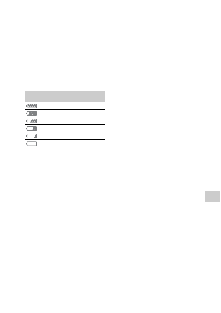
• Be sure to set the POWER switch to OFF when
not recording or playing back on your
camcorder. The battery pack is also consumed
when your camcorder is in recording standby or
playback pause.
• Have spare battery packs ready for 2 or 3 times
the expected recording time, and make trial
recordings before making the actual recording.
• Do not expose the battery pack to water. The
battery pack is not water resistant.
About the remaining battery indicator
• Check the level with the following indicators
displayed on the LCD screen.
Battery remaining
Detected voltage
indicator
7.4 –
7.2 – 7.3
7.0 – 7.1
6.8 – 6.9
6.6 – 6.7
– 6.5
• The displayed level may not be correct under
certain circumstances.
• When the power goes off even though the
remaining battery time indicator indicates that
the battery pack has enough power to operate,
charge the battery pack fully again. Remaining
battery time will be indicated correctly. Note,
however, that the battery indication will not be
restored if it is used in high temperatures for a
long time, or if left in a fully charged state, or
when the battery pack is frequently used. Use
the remaining battery time indication as a rough
guide only.
About storage of the battery pack
• If the battery pack is not used for a long time,
fully charge the battery pack and use it up on
your camcorder once a year to maintain proper
function. To store the battery pack, remove it
from your camcorder and put it in a dry, cool
place.
• To discharge the battery pack on your
camcorder completely, leave your camcorder in
recording standby until the power goes off
(page 19).
About battery life
• Battery capacity decreases over time and
through repeated use. If decreased usage time
between charges becomes significant, it is
probably time to replace it with a new one.
• Each battery’s life is governed by storage,
operating and environmental conditions.
About charging the battery pack
• Use the Charger (supplied) to charge the
designated batteries only. If you charge other
types of batteries, those batteries may leak, heat
up, burst, or give an electric shock, resulting in
burns or injury.
• Remove the charged battery from the Charger.
• The charge lamp of the supplied Charger
flashes in 2 patterns as follows:
Fast-flashing...Turns on and off rapidly at about
0.15-second intervals.
Slow-flashing...Turns on and off alternately for
about 1.5 seconds, and turns off completely for
about 1.5 seconds. The lamp repeats this
sequence.
• If the charge lamp is fast-flashing, remove the
battery that is being charged, and then reattach
the same battery again firmly. If the charge
lamp continues fast-flashing, the cause could be
that the battery is damaged, or the battery is not
a designated type. Check the battery to confirm
whether it is a designated type or not. If it is a
designated type, remove the battery first, and
then attach a brand-new battery or another
known-to-be-good battery to see if the Charger
is working correctly. If the Charger is working
correctly, the cause could be that the battery is
damaged.
• If the charge lamp is slow-flashing, the Charger
is in standby mode and charging is suspended.
When the ambient temperature is out of the
appropriate temperature range for charging, the
Charger suspends charging automatically and
enters standby mode. When the ambient
temperature returns to an appropriate
temperature, the Charger restarts charging and
the charge lamp lights up. We recommend
charging the battery pack in an ambient
temperature of from 10 °C to 30 °C (50 °F to
86 °F).
Appendices
Important Notes on Operation
55
Page 56

About handling of your camcorder
On use and care
• Do not use or store the camcorder and
accessories in the following locations.
—Anywhere extremely hot or cold. Never
leave them exposed to temperatures above
60 °C (140 °F), such as under direct
sunlight, near heaters or in a car parked in
the sun. They may malfunction or become
deformed.
—Near strong magnetic fields or mechanical
vibration. The camcorder may malfunction.
—Near strong radio waves or radiation. The
camcorder may not be able to record
properly.
—Near AM receivers and video equipment.
Noise may occur.
—On a sandy beach or anywhere dusty. If
sand or dust gets in your camcorder, it may
malfunction. Sometimes this malfunction
cannot be repaired.
—Near windows or outdoors, where the LCD
screen, the viewfinder, or the lens may be
exposed to direct sunlight. This damages the
inside of the viewfinder or the LCD screen.
—Anywhere very humid.
• Operate your camcorder on DC 7.2 V (battery
pack) or DC 8.4 V (AC Adaptor).
• For DC or AC operation, use the accessories
recommended in these operating instructions.
• Do not let your camcorder get wet, for example,
from rain or sea water. If your camcorder gets
wet, it may malfunction. Sometimes this
malfunction cannot be repaired.
Appendices
• If any solid object or liquid gets inside the
casing, unplug your camcorder and have it
checked by a Sony dealer before operating it
any further.
• Avoid rough handling, disassembling,
modifying, physical shock, or impact such as
hammering, dropping or stepping on the
product. Be particularly careful of the lens.
• Do not use a deformed or damaged battery pack.
• Keep the POWER switch setting to OFF when
you are not using your camcorder.
• Do not wrap your camcorder with a towel, for
example, and operate it. Doing so might cause
heat to build up inside.
• When disconnecting the power cord (mains
lead), pull it by the plug and not the lead.
• Do not damage the power cord (mains lead)
such as by placing anything heavy on it.
• Keep metal contacts clean.
• Keep the Wireless Remote Commander and
button-type battery out of children’s reach. If
the battery is accidentally swallowed, consult a
doctor immediately.
• If the battery electrolytic liquid has leaked,
—consult your local authorized Sony service
facility.
—wash off any liquid that may have contacted
your skin.
—if any liquid gets in your eyes, wash with
plenty of water and consult a doctor.
When not using your camcorder for a long time
• Turn on the camcord er and record and play back
images about once a month to keep it in an
optimum state for a long time.
• Use up the battery pack completely before
storing it.
Moisture condensation
If your camcorder is brought directly from a cold
place to a warm place, moisture may condense
inside your camcorder and cause a malfunction of
your camcorder.
If moisture condensation has occurred
Leave your camcorder for about 1 hour without
turning it on.
Note on moisture condensation
Moisture may condense when you bring your
camcorder from a cold place into a warm place
(or vice versa) or when you use your camcorder in
a humid place as shown below.
• When you bring your camcorder from a ski
slope into a place warmed up by a heating
device.
• When you bring your camcorder from an air
conditioned car or room into a hot place outside.
• When you use your camcorder after a squall or
a shower.
• When you use your camcorder in a hot and
humid place.
How to avoid moisture condensation
When you bring your camcorder from a cold
place into a warm place, put your camcorder in a
plastic bag and seal it tightly. Remove the bag
when the air temperature inside the plastic bag
has reached the ambient temperature (after about
1 hour).
Important Notes on Operation
56
Page 57

LCD screen
• Do not exert excessive pressure on the LCD
screen, as it may cause damage.
• If your camcorder is used in a cold place, a
residual image may appear on the LCD screen.
This is not a malfunction.
• While using your camcorder, the back of the
LCD screen may heat up. This is not a
malfunction.
To clean the LCD screen
The surface of the LCD screen is coated. If you
scratch the surface, the coating may be come off.
Mind the following points when cleaning and
handling it.
• If hand grease or hand cream remains on the
screen, the coating comes off more easily. Wipe
it early.
• The coating may be scratched if you wipe the
screen with a tissue, etc.
• Remove the dust or sand with a blower, etc.
before wiping the dirt.
• Use a soft cloth (a cloth for glasses, etc.) gently
to clean the dirt.
On handling the casing
• If the casing is soiled, clean the camcorder body
with a soft cloth lightly moistened with water,
and then wipe the casing with a dry soft cloth.
• Avoid the following to avoid damage to the
finish.
—Using chemicals such as thinner, benzine,
alcohol, chemical cloths, repellent,
insecticide and sunscreen.
—Handling with above substances on your
hands.
—Leaving the casing in contact with rubber or
vinyl objects for a long period of time.
About care and storage of the lens
• Wipe the surface of the lens clean with a soft
cloth in the following instances:
—When there are fingerprints on the lens
surface.
—In hot or humid locations
—When the lens is exposed to salty air such as
at the seaside.
• Store in a well-ventilated location subject to
little dirt or dust.
• To prevent mold, periodically clean the lens as
described above.
On charging the pre-installed rechargeable
battery
Your camcorder has a pre-installed rechargeable
battery to retain the date, time, and other settings
even when the POWER switch is set to OFF. The
pre-installed rechargeable battery is always
charged while your camcorder is connected to the
wall outlet (wall socket) via the AC Adaptor or
while the battery pack is attached. The
rechargeable battery will be fully discharged in
about 3 months if you do not use your
camcorder at all without the AC Adaptor
connected or the battery pack attached. Use your
camcorder after charging the pre-installed
rechargeable battery.
However, even if the pre-installed rechargeable
battery is not charged, the camcorder operation
will not be affected as long as you are not
recording the date.
Removing dust from inside the
viewfinder
1 Remove the eye piece of the viewfinder.
Slide down the viewfinder release lever and
hold it at the position (1), then lift the eye
piece of the viewfinder as indicated with the
arrow in the illustration (2).
Appendices
Important Notes on Operation
57
Page 58

2 Remove dust inside the eye piece and
viewfinder with a blower.
To prevent electromagnetic interference
from portable telephones, wireless
devices, etc.
The use of portable telephones, wireless devices,
etc., near this unit can result in malfunctions and
interference with audio and video signals.
It is recommended that such equipment near this
unit is powered off.
About the LCD screen
• Do not leave the LCD screen facing direct
sunlight, as this may damage the LCD screen.
• Do not press/swipe the LCD screen forcefully,
or leave objects on the LCD screen, as it may
cause a malfunction, such as picture
irregularity, etc.
• The LCD screen may become warm in use. This
is not a malfunction.
Note on the display
• Pictures on the LCD screen and viewfinder
screen may be distorted by the following
operations:
—Changing the video format
—Starting playback from the Thumbnail
screen
—Reversing the LCD screen
• When you change the eye direction in the
viewfinder, you may see primary colors red,
green, and blue, but this is not a defect of the
camcorder. These primary colors are not
recorded on any recording media.
Fragmentation
If pictures cannot be recorded/reproduced
properly, try formatting the recording medium.
While repeating picture recording/playback with
a certain recording medium for an extended
period, files in the medium may be fragmented,
disabling proper recording/storage. In such a
case, make a backup of clips in the medium then
perform formatting of the medium using “Format
Media” (page 46) in the Media menu.
About the stuck pixels
Appendices
The LCD sc reen fitted to this un it is manufactured
with high precision technology, giving a
functioning pixel ratio of at least 99.99%. Thus a
very small proportion of pixels may be “stuck”,
either always off (black), always on (red, green,
or blue), or flashing. In addition, over a long
period of use, because of the physical
characteristics of the liquid crystal display, such
“stuck” pixels may appear spontaneously. These
problems are not a malfunction, and will not be
recorded on recording media.
Important Notes on Operation
58
Page 59

Formats and Limitations of Outputs
Video formats and output signals
Output formats from the HDMI OUT connector
Region setting Recording format
setting
“NTSC/PAL Area” in
“Country” of System
menu
NTSC Area 3840×2160 59.94P 150 3840×2160P 3840×2160 59.94P*
PAL Area 3840×2160 50P 150 3840×2160P 3840×2160 50P*
* Compatible with the Sony transmission system.
You can connect the camcorder to a Sony 4K television, or a 4K monitor.
Picture resolution is Y:Cb:Cr=4:2:0.
“Video Format” in
“Rec Format” of
System menu
3840×2160 29.97P 100
3840×2160 29.97P 60
3840×2160 23.98P 100
3840×2160 23.98P 60
1920×1080 59.94P 50 1920×1080P 1920×1080 59.94P
1920×1080 29.97P 50 1920×1080P 1920×1080 59.94P
1920×1080 23.98P 50 1920×1080P 1920×1080 23.98P
3840×2160 25P 100
3840×2160 25P 60
1920×1080 50P 50 1920×1080P 1920×1080 50P
1920×1080 25P 50 1920×1080P 1920×1080 50P
HDMI output setting Output signal/
Conversion method
“HDMI” in “Output
Output signal
Format” of Video menu
1920×1080P 1920×1080 59.94P
1920×1080i 1920×1080 59.94i
720×480P 720×480 59.94P
3840×2160P 3840×2160 29.97P
1920×1080P 1920×1080 59.94P
1920×1080i 1920×1080 59.94i
720×480P 720×480 59.94P
3840×2160P 3840×2160 23.98P
1920×1080P 1920×1080 23.98P
1920×1080i 1920×1080 59.94i
720×480P 720×480 59.94P
1920×1080i 1920×1080 59.94i
720×480P 720×480 59.94P
1920×1080i 1920×1080 59.94i
720×480P 720×480 59.94P
1920×1080i 1920×1080 59.94i
720×480P 720×480 59.94P
1920×1080P 1920×1080 50P
1920×1080i 1920×1080 50i
720×576P 720×576 50P
3840×2160P 3840×2160 25P
1920×1080P 1920×1080 50P
1920×1080i 1920×1080 50i
720×576P 720×576 50P
1920×1080i 1920×1080 50i
720×576P 720×576 50P
1920×1080i 1920×1080 50i
720×576P 720×576 50P
Appendices
Formats and Limitations of Outputs
59
Page 60

Output formats from the VIDEO OUT connector
Signals to the VIDEO OUT connector cannot be output when “HDMI” in “Output Format” of the Video
menu is set to “3840×2160P.”
Video output signal
Setting for the region where the camcorder is used
“NTSC/PAL Area” in “Country” of System menu
NTSC Area 720×486 59.94i
PAL Area 720×576 50i
VIDEO output
Appendices
Formats and Limitations of Outputs
60
Page 61

Error/Warning Indications
The camcorder informs you of situations where warning, caution, or an operation check is required,
through messages on the LCD/viewfinder screen, the recording lamp, and a buzzer.
The buzzer is output to the headphones connected via the headphone connector.
Error indications
The camcorder stops operation after the following indications.
Error indication on
LCD/viewfinder
C:04:ss The battery pack is not an “InfoLITHIUM” battery pack. Use
C:06:ss The battery pack temperature is high. Change the battery
C:32:ss Remove the power source. Reconnect it and operate your
E:20:ss/E:40:ss/
E:41:ss/E:50:ss/
E:51:ss/E:61:ss/
E:62:ss/E:92:ss/
E:94:ss/E:95:ss
Warning indications
When one of the following indications is generated, follow the message to resolve the problem.
Warning indication
on LCD/viewfinder
Media Near Full Intermittent Flashing Free space on the XQD memory card has become
Media Full Continuous Rapidly
Battery Near End Intermittent Flashing The battery power will be discharged soon.
Battery End Continuous Rapidly
Battery Temperature
High
Turn Power Off
Temperature High Intermittent Flashing The internal temperature has risen above a safe operation
Battery Error
Please Change Battery
Buzzer Recording
lamp
Buzzer Recording
lamp
flashing
flashing
Cause and measures
an “InfoLITHIUM” battery pack (page 54).
pack or place it in a cool place.
camcorder again.
Perform the following steps.
1 Check the list, and inspect your camcorder.
2 Disconnect the power source, attach the power source again
after about 1 minute, and turn the camcorder on.
3 Contact your Sony dealer or local authorized Sony service
facility.
Cause and measures
insufficient.
Replace it with another at the earliest opportunity.
No space is left on the XQD memory card. Recording, clip
copying and clip division cannot be performed.
Replace it with another.
Charge the battery pack at the earliest opportunity.
The battery pack is discharged. Recording cannot be
performed.
Stop operation and change the battery pack.
The temperature of the battery pack has risen above a safe
operation limit.
The camcorder turns off automatically.
limit.
Suspend operation, turn off the power, and wait until the
temperature falls.
An error was detected with the battery pack.
Replace the battery pack with a normal one.
Appendices
Error/Warning Indications
61
Page 62

Warning indication
on LCD/viewfinder
Unknown Media(A)*
Please Change
Media Error
Media(A) Needs to be
Restored*
Media Error
Cannot Record to
Media(A)*
Media Error
Cannot Use Media(A)*
Will Switch Slots Soon This is an advanced notice that the camcorder will switch
Cannot Use Media(A)*
Unsupported File
System
Media Error
Playback Halted
Media(A) Error* Recording cannot be done, because an error occurred with the
Media Reached
Rewriting Limit
Change Media(A)*
Appendices
Cannot Use Media(A)*
Unsupported File
System
Battery Temperature
High
* “Media(B)” for the card in slot B.
Buzzer Recording
Cause and measures
lamp
A partitioned memory card or one that contains recorded
clips exceeding the number permitted with this camcorder is
loaded.
This card cannot be used with this camcorder. Remove it and
load a compatible card.
An error occurred with the memory card. The card requires
restoration.
Remove the card, load it again, and restore it.
Recording cannot be done, because the memory card is
defective.
Because playback may be possible, it is recommended to
replace it with another card after copying the clips, as
required.
Neither recording nor playback can be done, because the
memory card is defective.
It cannot be operated with this camcorder. Replace it with
another card.
from the current memory card to the other memory card for
continuous recording.
A card of a different file system or an unformatted card was
inserted. It cannot be used with this camcorder.
Replace it or format it with this camcorder.
An error occurred in reading data from the memory card, and
playback cannot be continued.
If this frequently occurs, change the memory card after
copying the clips, as required.
memory card.
If this frequently occurs, change the memory card.
The memory card comes to the end of its service life. Make a
backup copy and replace the card with another one as soon as
possible. Recording/playback may not be performed properly
if you continue to use the card.
For details, refer to the operating instructions of the memory
card.
A memory card with different file system is inserted.
Replace the card, format it with the camcorder.
Intermittent Flashing The temperature of the battery pack is rising.
Turn off the power and replace the battery pack with another
one or wait until the temperature falls.
Error/Warning Indications
62
Page 63

Licenses
On accessing software to which the GPL/LGPL applies
This product uses software to which the GPL/
LGPL applies. This informs you that you have a
right to have access to, modify, and redistribute
source code for these software programs under
the conditions of the GPL/LGPL.
The source code is provided on the internet. Use
the following URL and follow the download
instructions.
http://www.sony.net/Products/Linux/common/
search.html
We would prefer that you do not contact us about
the contents of the source code.
For the content of these licenses, see
“License1.pdf” in the “License” folder of the
supplied CD-ROM.
Adobe Reader must be installed on your
computer to view PDF files.
If Adobe Reader is not installed on your
computer, you can download it by accessing the
following URL.
http://get.adobe.com/reader/
Open software licenses
On the basis of license contracts between Sony
and the software copyright holders, this product
uses open software.
To meet the requirements of the software
copyright holders, Sony is obligated to inform
you of the content of these licenses.
For the content of these licenses, see
“License1.pdf” in the “License” folder of the
supplied CD-ROM.
Specifications
System
Video signal
4K image quality (3840×2160): UHDTV
HD image quality: HDTV
Video recording system
4K image quality (3840×2160): MPEG-4
AVC/H.264 XAVC S format ver.1.0
compatible
HD image quality: MPEG-4 AVC/H.264
XAVC S format ver.1.0 compatible
Audio recording system
Linear PCM 2ch (48 kHz 16-bit)
Recording media
XQD memory card
Image device
7.82 mm (1/2.3 type) CMOS sensor
Gross: Approx. 18 900 000 pixels
Effective (movie, 16:9): Approx. 8 300 000
pixels
Lens
G Lens
20 × (Optical)
Focal length
f=4.1 mm - 82.0 mm (3/16 in. - 3 1/4 in.)
When converted to a 35 mm still camera
31.5 mm - 630 mm (1 1/4 in. - 24 7/8 in.)
(16:9)
F1.6 - F3.4
Filter diameter: 72 mm (2 7/8 in.)
Color temperature
“Indoor” (3 200K)
“Outdoor” (5 600K)
“Color Temp.” (2 300K - 15 000K)
Minimum illumination
60P (NTSC Area):
4 lx (lux) (Fixed Shutter Speed 1/30, manual
gain (27 dB), auto iris (F1.6))
50P (PAL Area):
3 lx (lux) (Fixed Shutter Speed 1/25, manual
gain (27 dB), auto iris (F1.6))
Input/Output connectors
VIDEO OUT connector
Pin connector
1 Vp-p, 75 Ω (ohms) unbalanced, sync
negative
Appendices
Licenses / Specifications
63
Page 64

AUDIO OUT connectors
Pin connectors
-10 dBu (at load impedance 47 kΩ
(kilohms)), Output impedance with less than
2.2 kΩ (kilohms)
(0 dBu = 0.775 Vrms)
HDMI OUT connector
HDMI connector (Type A)
i (headphones) connector
Stereo-minijack (Ø 3.5 mm)
INPUT1/INPUT2 connectors
XLR 3-pin, female,
MIC: -50dBu: 3kΩ (kilohms)
LINE: +4 dBu: 10 kΩ (kilohms)
(0 dBu = 0.775 Vrms)
USB connector
Mass-storage: mini-B
Host: Type A
Remote connector
Stereo mini-minijack (Ø 2.5 mm)
LCD screen
Picture
8.8 cm (3.5 type, aspect ratio 16:9)
Total dot number
1 229 000 (854 × 480 × 3 [RGB])
Viewfinder
Picture
0.45 type, aspect ratio 16:9
Total dot number
Approx. 1 226 880
General
Power requirements
DC 7.2 V (battery pack)
DC 12 V 2.5 A (AC Adaptor)
Appendices
Average power consumption
During camera recording using the internal
microphone and LCD with normal brightness
NTSC Area:
4K: 14.5W (29.97P, 60Mbps)
HD: 15.7W (59.94P, 50Mbps)
PAL Area:
4K: 13.8W (25P, 60Mbps)
HD: 14.9W (50P, 50Mbps)
Operating temperature
0°C to 40°C (32°F to 104°F)
Storage temperature
-20 °C to +60 °C (-4 °F to +140 °F)
Dimensions (approx.)
Camcorder body only (including the
projecting parts):
189 mm × 193 mm × 362 mm
(7 1/2 in. × 7 5/8 in. × 14 3/8 in.) (w/h/d)
When recording (including the projecting
parts):
189 mm × 193 mm × 413 mm
(7 1/2 in. × 7 5/8 in. × 16 3/8 in.) (w/h/d)
(With the accessories (battery pack (NPF970), large eyecup) attached.)
Mass (approx.)
Camcorder body only:
2 440 g (87 oz)
When recording:
2 770 g (98 oz) (With the accessories (battery
pack (NP-F970), large eyecup) attached.)
AC Adaptor AC-NB12A
Power requirements
AC 100 V - 240 V, 50 Hz/60 Hz
Current consumption
0.65 A - 0.35 A
Power consumption
30 W
Output voltage
DC 12 V*
Operating temperature
0 °C to 45 °C (32 °F to 113 °F)
Storage temperature
-20 °C to +60 °C (-4 °F to +140 °F)
Dimensions (approx.)
49.5 mm × 28 mm × 99.5 mm
(1 31/32 in. × 1 1/8 in. × 3 15/16 in.) (w/h/d)
excluding the projecting parts
Mass (approx.)
200 g (7.1 oz) excluding the power cord
(mains lead)
* See the label on the AC Adaptor for other
specifications.
Charger AC-VL1
Power requirements
AC 100 V - 240 V, 50 Hz/60 Hz
Current consumption
0.35 A - 0.18 A
Power consumption
22 W
Output voltage
DC 8.4 V*
Operating temperature
0°C to 40°C (32°F to 104°F)
Storage temperature
-20 °C to +60 °C (-4 °F to +140 °F)
64
Specifications
Page 65

Dimensions (approx.)
136 mm × 51 mm × 90 mm
(5 3/8 in. × 2 1/8 in. × 3 5/8 in.) (w/h/d)
excluding the projecting parts
Mass (approx.)
270 g (9.6 oz) excluding the power cord
(mains lead)
* See the label on the Charger for other specifications.
Rechargeable battery pack NP-F970
Maximum output voltage
DC 8.4 V
Output voltage
DC 7.2 V
Maximum charge voltage
DC 8.4 V
Maximum charge current
3.0 A
Capacity
Typical: 47.5 Wh (6 600 mAh)
Minimum: 45 Wh (6 300 mAh)
Type
Li-ion
Design and specifications are subject to change without
notice.
• Manufactured under license from Dolby Laboratories.
Package configuration
• Microsoft, Windows, Windows Vista, and
Windows Media are trademarks or registered
trademarks of U.S. Microsoft Co rporation in the
U.S. and other countries.
• Mac and Mac OS are registered trademarks of
Apple Inc. in the U.S. and other countries.
• HDMI, HDMI logo, and High-Definition
Multimedia Interface are registered trademarks
of HDMI Licensing LLC in the United States
and other countries.
• Intel, Intel Core, and Pentium are trademarks or
registered trademarks of Intel Corporation or its
subsidiaries in the United States and other
countries.
• Adobe, the Adobe logo, and Adobe Acrobat are
either registered trademarks or trademarks of
Adobe Systems Incorporated in the United
States and/or other countries.
All other product names m entioned herein may be
the trademarks or registered trademarks of their
respective companies. Furthermore, ™ and “®”
are not mentioned in each case in this manual.
Charger (1) (AC-VL1)
Rechargeable battery pack NP-F970 (1)
AC Adaptor (1) (AC-NB12A)
Power cord (mains lead) (2)
A/V connecting cable (1)
HDMI cable (1)
USB cable (1)
Lens hood (1)
Large eyecup (1)
CD-ROM “License” (1)
Operating Guide (2)
On trademarks
• “Handycam” and are
registered trademarks of Sony Corporation.
• “XAVC S” and are trademarks of
Sony Corporation.
• XQD, and are trademarks of Sony
Corporation.
• “InfoLITHIUM” is a trademark of Sony
Corporation.
Specifications
Appendices
65
Page 66

Index
A
AC Adaptor 22
All Reset 47
Assignable Button 35, 46
Audio 29
Audio Input 44
Audio menu 44
Audio Output 44
Auto Exposure 41
AUTO/MANUAL switch 30
C
Camera menu 41
Charging time 22
Clip 29, 37
Clock 23
Clock Set 47
Color Bars 41
Country 47
Cueing up 29
H
Handle Zoom 41
Handle zoom 27
Handle zoom lever 27
Handle zoom switch 27
HDMI OUT connector 48, 59
Headphones connector 15
Hook for shoulder strap 15
Hours Meter 47
I
Indoor 32
“InfoLITHIUM” battery pack 54
IRIS button 30
Iris ring 30
L
Language 47
LCD screen 19, 24
LCD Setting 45
LCD/VF Menu 45
Lens 57
Lens cover lever 23
Lens hood with lens cover 23
D
Delete Clip 47
Detail 42
Display Clip Properties 38
E
Error Indications 61
Appendices
Expanded focus 28
External Monitor 48
F
Flicker Reduce 41
Focus 28
Focus ring 28
FOCUS switch 28
Format 26
Format Media 46
G
Gain 30, 41
GAIN button 30
Gain switch 30
Gamma 42
Index
66
M
Marker 45
Matrix 43
Media Full 26
Media menu 46
Media Near Full 26
MENU button 40
MIC+48V 33
Moisture condensation 56
MRW-E80 49
N
ND filter 31
Nonlinear editing 51
O
Offset White 42
One push button 32
OPTION button 37
Outdoor 32
Output Display 45
Output Format 44
Page 67

Output signal 59
P
Paint menu 42
Peaking 45
Power cord (mains lead) 21
Power zoom lever 27
Pre-installed rechargeable battery 57
PUSH (lens hood release) button 23
PUSH AUTO button 28
Push auto focus 28
W
Wall outlet (wall socket) 22
Warning Indications 61
White 42
White balance 31
White balance memory switch 32
WHT BAL button 31
Wide angle 27
X
XQD Memory Cards 25
R
Rec Format 46
Rec Lamp 46
Record button 27
S
SEL/SET dial 40
Setup menu 40, 41
Shoulder strap 15
Shutter speed 31
SHUTTER SPEED button 31
Skin Detail 43
SteadyShot 41
System menu 46
T
Telephoto 27
Thumbnail menu 37
Thumbnail screen 36
Time and date 23
Time Zone 23
U
USB cable 49
Using your camcorder abroad 54
UTC 23
Z
Zebra 45
Zoom 27
Zoom ring 27
Appendices
V
Version 47
VF Setting 45
Video format 59
Video menu 44
VIDEO OUT connector 48, 60
Viewfinder 19, 24
Viewfinder lens adjustment lever 24
Viewfinder release lever 57
Index
67
Page 68

Additional information on this product and
answers to frequently asked questions can be
found at our Customer Support Website.
Printed in China
 Loading...