

Sony ExwaveHAD DXC-C33, ExwaveHAD DXC-C33P Instructions For Use Manual
3-206-413-11 (1)
3CCD Color Video Camera
DXC-C33/DXC-C33P
3CCD Color Video
Camera
Instructions for Use
Instructions d’utilisation
Gebrauchsanweisung
Instrucciones de uso
(DXC-C33P only)
GB
FR
DE
ES
DXC-C33
DXC-C33P
© 2001 Sony Corporation
Owner’s Record
The model and serial numbers are located on
the side. Record these numbers in the spaces
provided below.
Refer to these numbers whenever you call
upon your Sony dealer regarding this
product.
Model No. Serial No.
You are cautioned that any changes or
modifications not expressly approved in this
manual could void your authority to operate
this equipment.
The shielded interface cable recommended
in this manual must be used with this
equipment in order to comply with the limits
for digital device pursuant to Subpart B of
Part 15 of FCC Rules.
WARNING
To prevent fire or shock hazard, do
not expose the unit to rain or
moisture.
To avoid electrical shock, do not
open the cabinet. Refer servicing to
qualified personnel only.
This apparatus must be earthed.
Symbol on the products
This symbol indicates the
equipotential terminal which
brings the various parts of a system
to the same potential.
For the customers in the U.S.A.
This equipment has been tested and found to
comply with the limits for a Class A digital
device, pursuant to Part 15 of the FCC
Rules. These limits are designed to provide
reasonable protection against harmful
interference when the equipment is operated
in a commercial environment.
This equipment generates, uses, and can
radiate radio frequency energy and, if not
installed and used in accordance with the
instruction manual, may cause harmful
interference to radio communications.
Operation of this equipment in a residential
area is likely to cause harmful interference in
which case the user will be required to
correct the interference at his own expense.
For the customers in the U.S.A. and
Canada
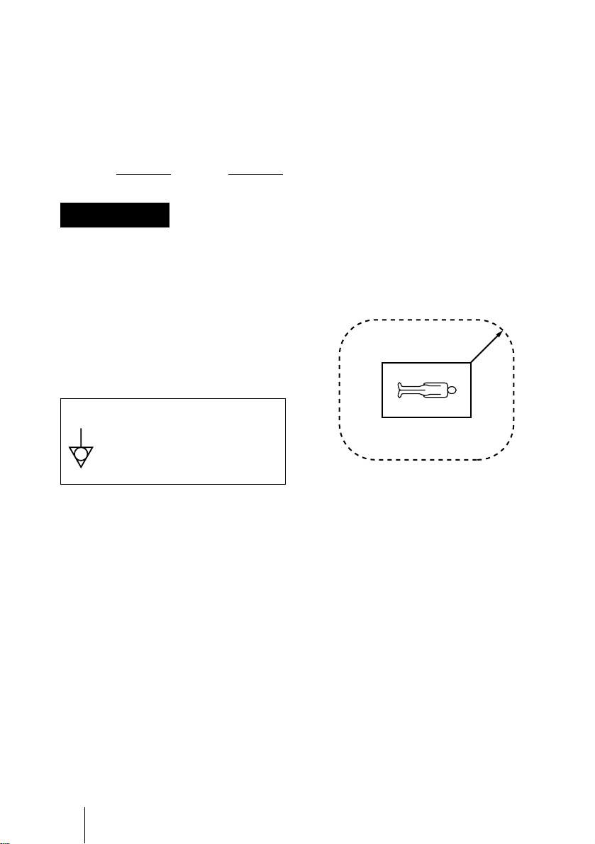
Model DXC-C33 is Non-Patient Equipment.
This unit can not be used in the vicinity of
patients.
* Patient Vicinity
R 1.83 m
(6 feet)
For the customers in Canada (for
DXC-C33)
This unit has been certified according to
Standard CSA C22.2 NO.601.1.
GB
2
For the customers in Europe (for
DXC-C33P)
Important safeguards/notice for use
in the medical environments
1. All the equipments connected to this unit
shall be certified according to Standard
IEC60601-1, IEC60950, IEC60065 or
other IEC/ISO Standards applicable to
the equipments.
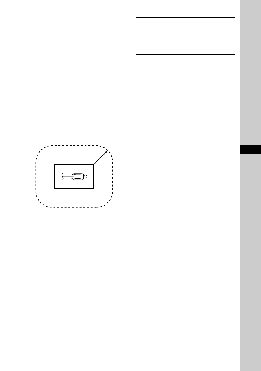
2. When this unit is used together with other
equipment in the patient area*, the
equipment shall be either powered by an
isolation transformer or connected via an
additional protective earth terminal to
system ground unless it is certified
according to Standard IEC60601-1.
* Patient Area
R 1.5 m
Caution
When you dispose of the unit or
accessories, you must obey the law in the
relative area or country and the regulation
in the relative hospital.
GB
3. The leakage current could increase when
connected to other equipment.
4. This equipment generates, uses, and can
radiate frequency energy. If it is not
installed and used in accordance with the
instruction manual, it may cause
interference to other equipment. If this
unit causes interference (which can be
determined by unplugging the power
cord from the unit), try these measures:
Relocate the unit with respect to the
susceptible equipment. Plug this unit and
the susceptible equipment into different
branch circuit. Consult your dealer.
(According to Standard EN60601-1-2
and CISPR11, Class B, Group 1)
GB
3

GB
4

Table of Contents
Overview
Features ..............................................6
Location and Functions of Parts and
Controls ..............................................7
Camera Head ................................7
Camera Control Unit ....................8
Adjusting and Setting With
Menus
About On-screen Menus ..................11
Operation Through Menus ...............12
EXPOSURE Menu ...........................13
CONTRAST Menu ..........................16
WHITE BALANCE Menu ...............17
ENHANCER Menu ..........................19
GENERAL Menu .............................20
SYSTEM Menu ................................22
SCENE FILE Menu .........................23
Operation
Shooting ...........................................25
Basic Shooting Procedure ..........25
Adjusting the Black Balance ......25
Adjusting the White Balance ......26
Adjusting the Picture Tone in a
Multi-Camera System .....27
Installation and
Connections
Installation ........................................28
Applicable Lens ..........................28
Mounting the Lens ......................28
Mounting a Microscope
Adaptor ...........................28
Mounting on a Tripod ................ 28
Attaching to a Wall or Ceiling ... 29
Connections ..................................... 30
Connecting Between the Camera
Head and Camera Control
Unit ................................. 30
Connecting the AC Power
Cord ................................ 30
Connecting to Video Equipment
With Composite Video
Input Connectors ............ 31
Connecting to Video Equipment
With S-Video Input
Connector ....................... 31
Connecting to Video Equipment
With RGB Inputs ............ 32
Connecting to Video Equipment
With DV Input
Connector ....................... 33
Connecting Two or More Cameras
— Multi-Camera
System ............................ 34
Connecting to a Remote Control
Unit ................................. 35
Connecting to a Computer ......... 37
Connections for Shooting Using a
Flash ............................... 38
Connections for Displaying a Freeze
Picture Using a Foot
Switch ............................. 39
Appendix
Precautions ...................................... 40
Typical CCD Phenomena ................ 40
List of Messages .............................. 41
WEN Pulse Timing Chart ................ 42
Specifications .................................. 43
Menu Configuration ........................ 46
GB
5

Overview
B
Features
High-quality images
• The high density 1/3 type, three-chip
Exwave HAD
some 380,000 (DXC-C33) or 430,000
(DXC-C33P) effective picture elements
(pixels), offers superior picture quality:
850 TV lines of high horizontal resolution,
high sensitivity of F8 at 2,000 lx, an
excellent signal-to-noise ratio of 62 dB
(DXC-C33) or 61 dB (DXC-C33P) and a
low smear level.
* Exwave HADTM: Exwave Hole-Accumulated
Diode
“Exwave HAD
Corporation.
**CCD: Charge-Coupled Device
Precise picture control functions
by the adoption of LSI digital signal
processing technology
• DynaLatitude processing enables you to
adjust contrast finely according to the
luminance signal level of each picture
element.
• The DCC+ (Dynamic Contrast Control
plus) function minimizes the phenomena
whereby the whole screen turns white or a
part of the image becomes colorless when
shooting a very bright object.
• The Partial Enhance function enables you
to adjust the sharpness and tint of only a
specified color.
TM*
CCD**, containing
TM
” is a trademark of Sony
i.LINK (DV) digital interface
equipped
Connecting a DVCAM format digital video
cassette recorder to this camera allows you
to make easy digital recording.
Freeze and long term exposure
functions
By utilizing the built-in one frame memory
(10 bits), freeze function and long term
exposure function can be easily controlled.
RS-232C interface
The camera can be controlled from a
computer via the RS-232C interface.
For details, contact your authorized Sony
dealer.
Compact and lightweight Remote
Camera Head System
• The camera head is compact (38 × 32 × 40
• Versatile use of the camera is realized by
GB
1
/2 × 1 5/16 × 1 5/8 inches)) and very
mm (1
light (48 g (1.7 oz)), allowing easy
mounting on a device which was difficult
to be mounted.
connecting the camera head and the
camera control unit with the optional
camera cable, which enables you to extend
the connecting distance up to 30 m (98
feet).
Features
6
Location and
Functions of Parts
and Controls
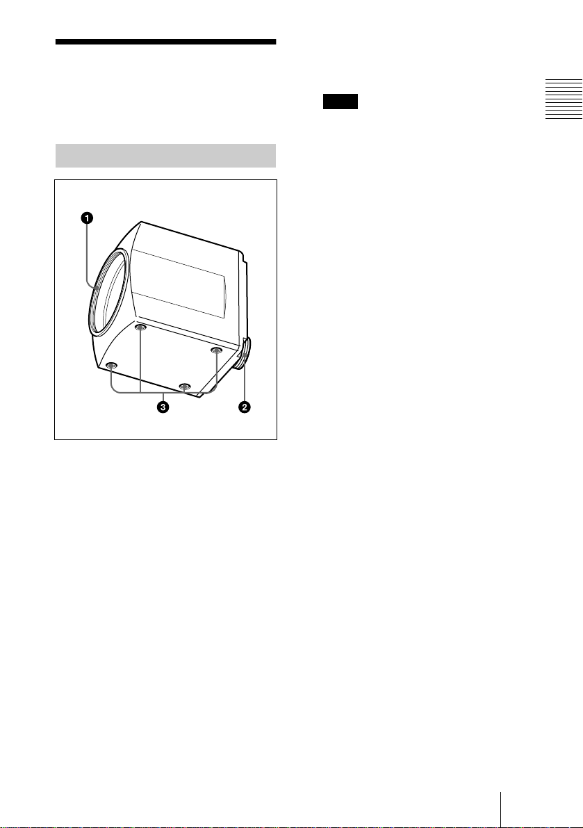
Camera Head
1 Lens Mount
Attach a C-mount lens or microscope
adaptor.
Note
Be sure to use a lens whose projected part
from the lens mount surface is less than 4.3
mm (3/16 inches). Mounting the lens with
a projected part greater than 4.3 mm (3/16
inches) may damage the internal
mechanism of the camera.
2 Camera cable connector (20-
pin)
Connects to the CAMERA connector on
the camera control unit with the optional
CCMC-20P05/10/30 camera cable.
3 Screw holes
Use these holes (M3, depth: 3 mm (1/8
inches)) to attach the supplied tripod
adaptor to the camera head for mounting
the camera head on a wall, ceiling or
tripod.
Overview
Location and Functions of Parts and Controls
GB
7
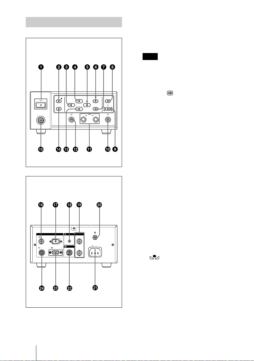
Camera Control Unit
Front
1
!
(power) switch and indicator
Press the switch down to turn on the
power of the unit. The indicator lights in
green. To turn off the power, press the
switch again. The indicator turns off.
Note
Be sure to connect the camera head and
camera control unit with the camera cable
(not supplied) before you turn the camera
on or off.
CAMERA
Rear
VIDEO
SCENE FILE
SELECT
GAIN
0dB 24dB
FS/TRIG IN
REMOTE
BLACK MENU
VD/SYNC
FREEZE
BARS
OUT PUT EXT SYNC
DV
RGB/SYNCS-VIDEO
WHITE
ENTER LOCK
GAINRED BLUE AE LEVEL
–+ –+ –+
HD
AC IN
AE AREA
SELECT
2 FREEZE button and indicator
Pressing this button stores an image in
the built-in frame memory and outputs it
as a freeze picture. When the freeze
picture mode activates, the indicator
lights. Pressing the button again turns
off the indicator and cancels the freeze
picture mode. The image currently shot
is displayed on a monitor screen.
3
B
/FILE SELECT button
While the menu is displayed:
Decreases the setting value or changes
the setting. Also use this button for an
AE window setting, etc.
While the normal screen is displayed:
Switches the user preset file between A
and B.
4
V
/BLACK (black balance) button
While the menu is displayed: Moves
the menu cursor upward. Also use this
button for an AE window setting, etc.
While the normal screen is displayed:
Activates the automatic black balance
adjustment.
5
b
/ WHITE (white balance)
button
While the menu is displayed: Increases
the setting value or changes the setting.
Also use this button for an AE window
setting, etc.
While the normal screen is displayed:
Activates the automatic white balance
adjustment when MODE is set to AWB
in WHITE BALANCE menu.
GB
Location and Functions of Parts and Controls
8

6 MENU button
Displays the MAIN menu on a monitor
screen. Press again to exit the menu.
When a setting menu is displayed, press
this button to return to the MAIN menu.
For menu operations, see “Operation
Through Menus ” on pag e 12 .
7 ENTER button
Selects a setting menu in the MAIN
menu. Also use this button for an AE
window setting, etc.
8 AE AREA SELECT button
Selects the AE window set with the
menu. Each press of the button selects
the AE AREA 1 or AE AREA 2. The
selected AE area is displayed on a
monitor screen for about a second.
Note
The button functions only when GAIN is
set to AGC or SHUTTER is set to CCDIRIS.
9 LOCK button and indicator
When you press this button to make the
indicator light, no buttons on the camera
control unit except for the ! (power)
switch function. Pressing the button
again turns off the indicator and cancels
lock mode. You can use any button. The
lock mode retains after the unit is turned
off.
q;
2
AE LEVEL control
Adjusts the auto exposure focusing point
when the camera is set to AGC or CCDIRIS mode. Turning the control
clockwise increases the value, and
turning it counterclockwise decreases
the value.
When SHUTTER is set to KNOB, the
shutter speed and video gain can be
adjusted with this control. Turning it
counterclockwise adjusts the shutter
speed. Turning it clockwise adjusts the
video gain. In KNOB setting, the 2
GAIN control does not function.
qa GAIN RED/BLUE controls
Use these controls for fine adjustment of
white balance when AWB or ATW
mode is selected. Also use them to adjust
the red and blue gain when adjusting the
white balance manually. Turning the
control clockwise sets to the positive
levels. Turning it counterclockwise sets
to the negative levels.
qs
2
GAIN control
Adjusts the gain level. Turning the
control adjusts the level in the range
from 0 to 24 dB.
qd
v
button
Moves the menu cursor downward. Also
use this button for an AE window
setting, etc.
qf BARS (color bars output) button
Outputs the color bar signal. Press again
to revert to video signal output.
For monitor adjustment, contact your
authorized Sony dealer.
qg CAMERA connector (20-pin)
Connects to the camera cable connector
on the camera head using the CCMC20P05/10/30 camera cable (not
supplied).
qh VIDEO OUTPUT connector
(BNC type)
Outputs a composite video signal.
*
qj
DV connector (6-pin)
The connector is especially designed to
output signals in DV format that
complies with i.LINK. Used to connect
the video equipment equipped with the
DV connector.
* is a trademark of Sony Corporation
and indicates that this product is in
agreement with IEEE1394–1995
specifications and their revisions.
Overview
Location and Functions of Parts and Controls
GB
9

qk FS/TRIG IN (Foot Switch/
Trigger input) connector (stereo
minijack)
Connects the optional foot switch.
When the camera is in strobe mode,
connects a commercially available slave
unit.
Note
The foot switch must comply with
Standard UL2601-1/EN60601-1.
For details on the foot switch, consult
with an authoriz ed Sony dealer.
ql EXT SYNC (external sync) (HD,
VD/SYNC) connectors (BNC
type)
Inputs reference sync signals for
synchronizing the camera operation.
When using the internal sync signals,
outputs the HD/VD or composite sync
signals.
w; Equipotential ground
terminal
Used to connect with the equipotential
plug to bring the various parts of a
system to the same potential.
Refer to “Important safeguard s /notice
for use in the medical environments” on
page 3.
wa
-
AC IN socket
Connects the supplied AC power cord.
ws REMOTEconnector (mini
DIN 8-pin)
Connects to the RM-C950 remote
control unit (not supplied).
wd RGB/SYNC connector (D-
sub 9-pin)
Outputs RGB signals and their
respective sync signals.
wf S VIDEO OUTPUT
connector (mini DIN 4-pin)
Outputs an S video (Y/C video) signal.
GB
Location and Functions of Parts and Controls
10
Adjusting and Setting With Menus
B
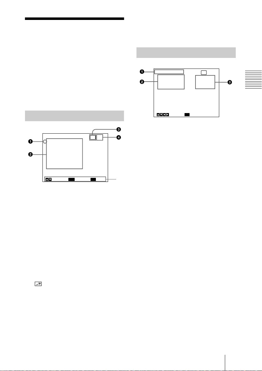
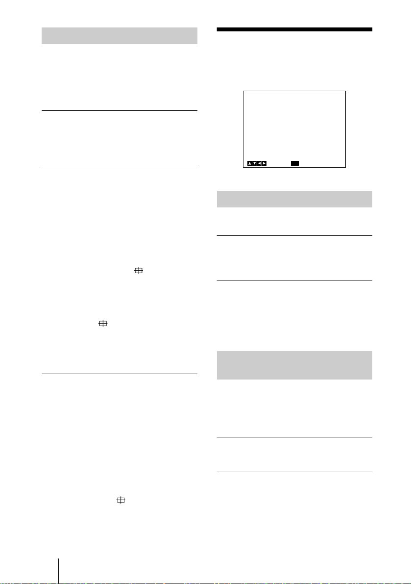
About On-screen
Menus
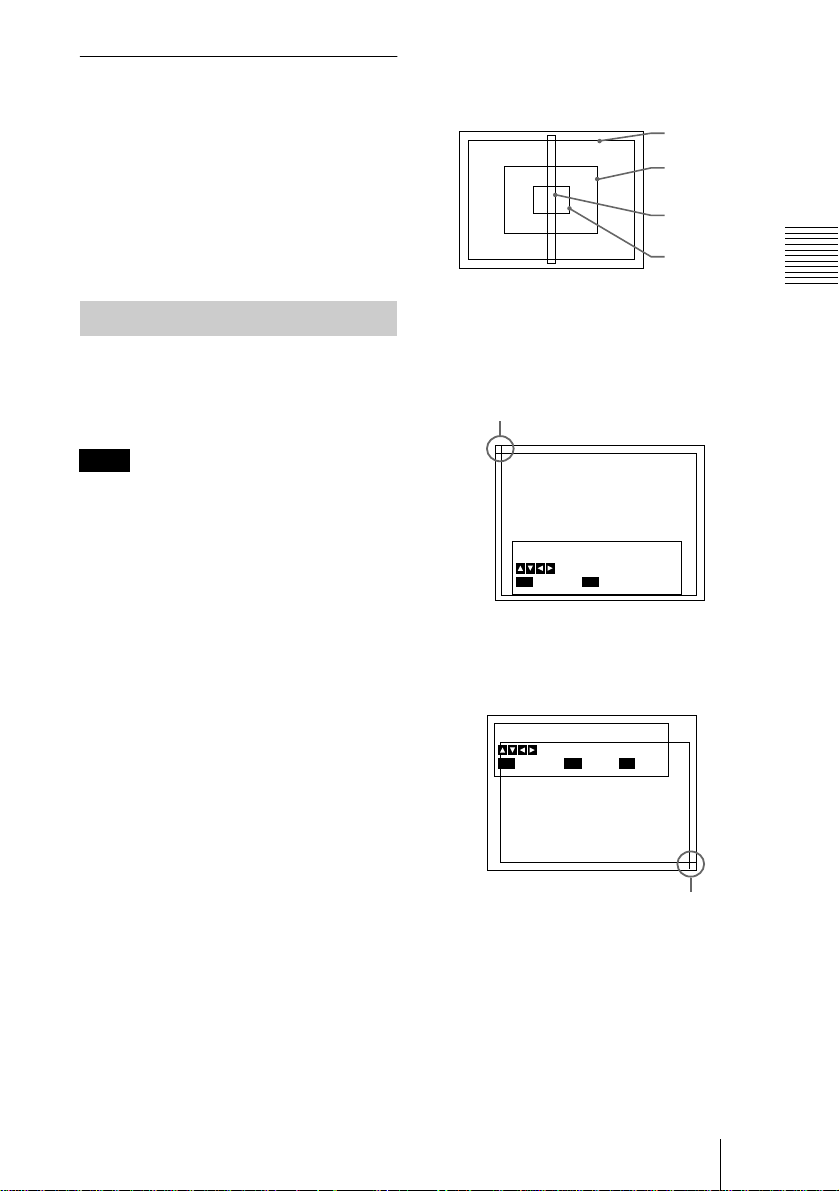
5 Operational message
Indicates how to operate the currently
displayed menu.
Camera operational settings can be changed
through simple adjustment of the settings on
the on-screen menus.
This section explains how to read the onscreen menu before starting menu operation.
For the menu configurat ion of the camera,
see page 46.
MAIN Menu
Next
RM
MENU
[A]
ExitSelect
5
<MAIN>
>EXPOSURE
CONTRAST
WHITE BALANCE
ENHANCER
GENERAL
SYSTEM
SCENE FILE
ENTER
1 Cursor
Selects a setting menu or setting item.
Move the cursor up or down using the V
or v button.
2 Setting menu items
When you select the desired item with
the V or v button and press the ENTER
button, the setting menu for adjustment
and setting is displayed.
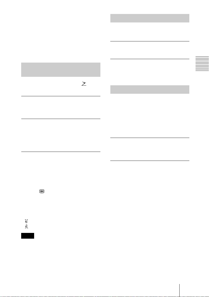
Setting Menu
MENU
RM
[A]
STEP
0dB
OFF
BackSelect
<EXPOSURE>
>GAIN
STEP
SHUTTER
1 Setting menu
Indicates the currently selected setting
menu.
2 Setting items
Indicates the items that can be adjusted
in each setting menu.
Select the item by moving the cursor
beside it with the V or v button.
3 Set values
The currently set values are displayed.
Change the values using the B or b
button.
For the initial set value on each item, see
“Menu Configuration” on page 46.
Adjusting and Setting With Menus
3 Remote control unit indicator
Indicates when the RM-C950 remote
control unit is connected to the
REMOTE connector on the rear of
the camera control unit.
4 User preset file
You can store two types of preset
adjustments into files A and B. Indicates
the currently selected preset file (A or
B).
For details, see “SCENE FILE Menu”
on page 23.
About On-screen Menus
11
GB
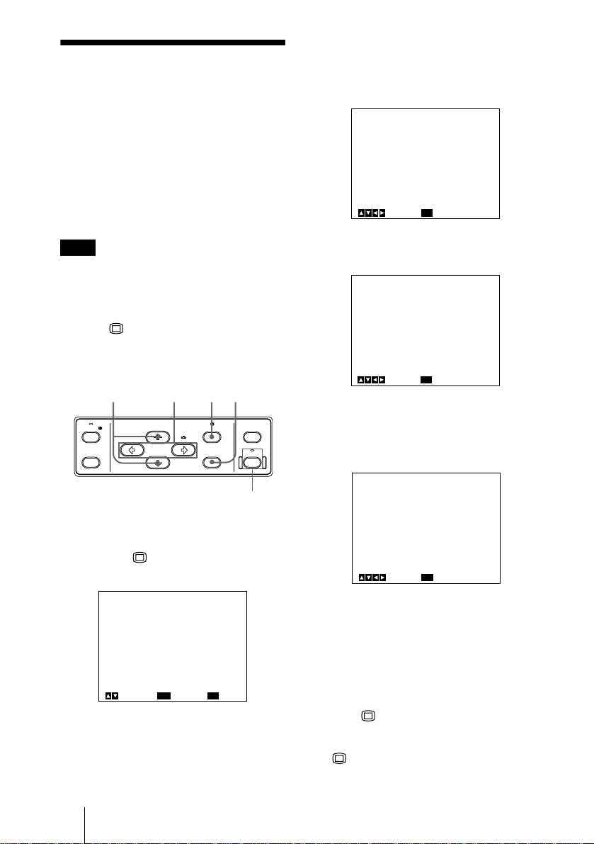
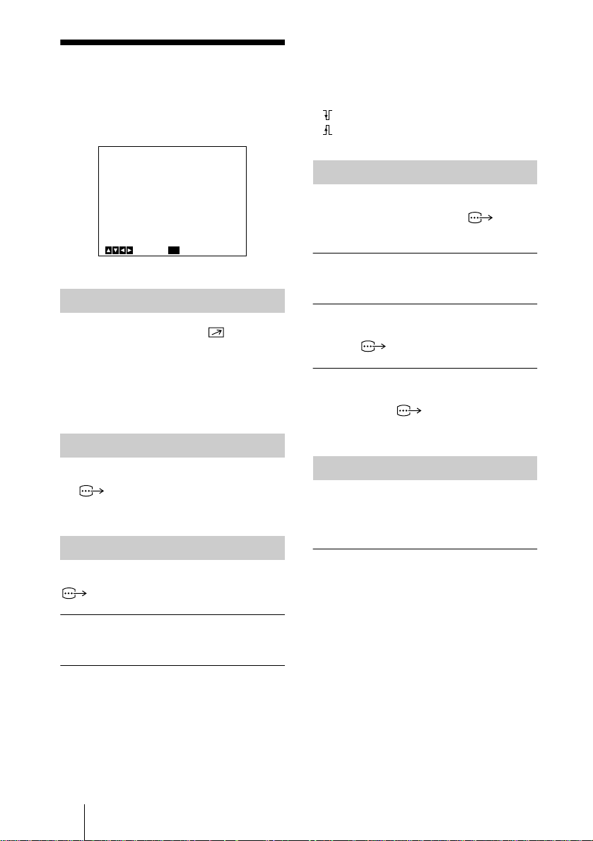
Operation Through
Menus
2
Move the cursor to the menu item to
V
be set by pressing the
or v button,
then press the ENTER button.
The setting menu is displayed.
To change the settings on the menu, proceed
as follows.
Some of the settings, however, cannot be
adjusted on the menu. Use the controls on
the front of the camera control unit to adjust
them.
For details, see page 13.
Note
Before starting menu operation, make sure
that the LOCK indicator on the front of the
camera control unit is not lit. When it is lit,
the menu will not be displayed even if you
press the MENU button. If the LOCK
indicator lights, press the LOCK button to
turn the indicator off, then operate the menu.
142,3 2
FREEZE
BARS
BLACK MENU
SCENE FILE
SELECT
WHITE
AE AREA
SELECT
ENTER LOCK
LOCK button
and indicator
<EXPOSURE>
>GAIN
STEP
SHUTTER
MENU
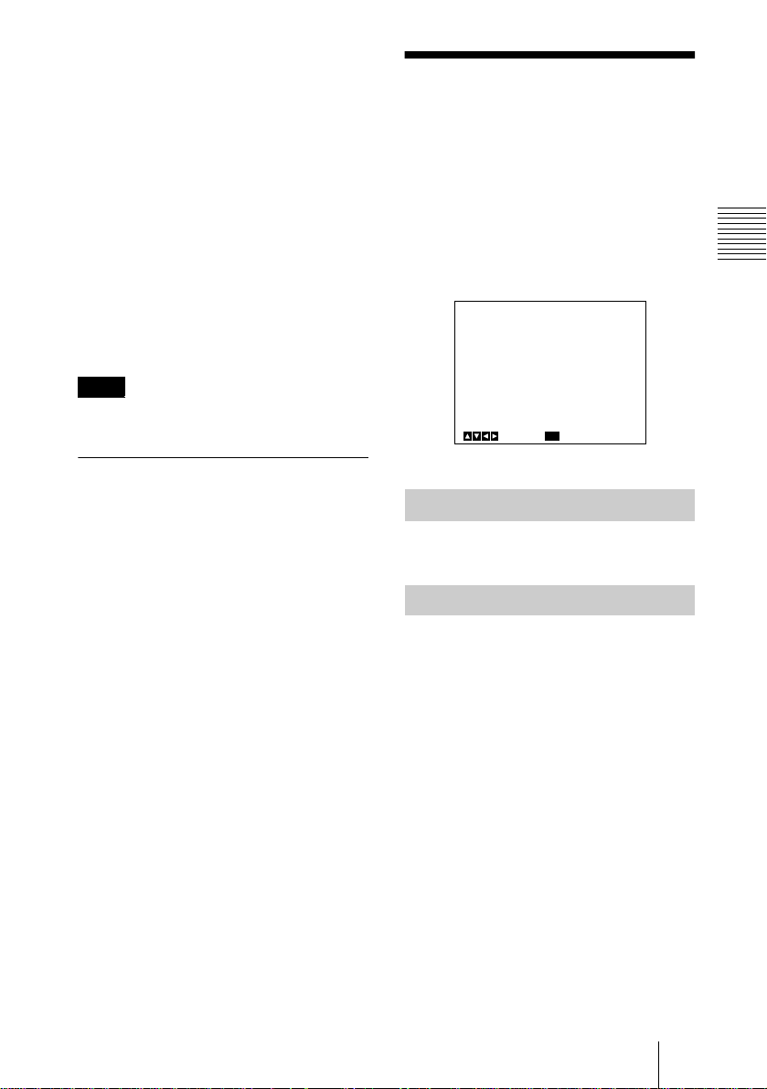
3
Move the cursor to the item to be
adjusted by pressing the
<EXPOSURE>
GAIN
STEP
>SHUTTER
MENU
4
Change the value by pressing the B or
b
button.
BackSelect
BackSelect
[A]
STEP
0dB
OFF
V
or v button.
[A]
STEP
0dB
OFF
Holding down the button changes the
value quickly.
<EXPOSURE>
GAIN
STEP
>SHUTTER
SPEED
[A]
STEP
0dB
STEP
OFF
1
Press the MENU button.
The MAIN menu appears.
<MAIN>
>EXPOSURE
CONTRAST
WHITE BALANCE
ENHANCER
GENERAL
SYSTEM
SCENE FILE
ENTER
GB
Operation Through Menus
12
Next
[A]
MENU
MENU
BackSelect
To reset to the initial set value
Select the item to be reset, then press the B
and b buttons simultaneously.
For the initial set value on each item, see
“Menu Configuration” on page 46.
ExitSelect
To return to the normal screen
Press the MENU button while the MAIN
menu is displayed.
While each setting menu is displayed, press
the MENU button to return to the MAIN
menu, then press it again to return to the
normal screen.
Adjusting the Setting Items
With the Controls on the
Front of the Camera Control
Unit
Use the controls on the front of the camera
control unit to adjust some of the setting
items such as gain and white balance.
For details on sett ing individual items, see
the relevant menu pages.
AE AREA SELECT button
FREEZE
BARS
BLACK MENU
SCENE FILE
SELECT
WHITE
AE AREA
SELECT
ENTER LOCK
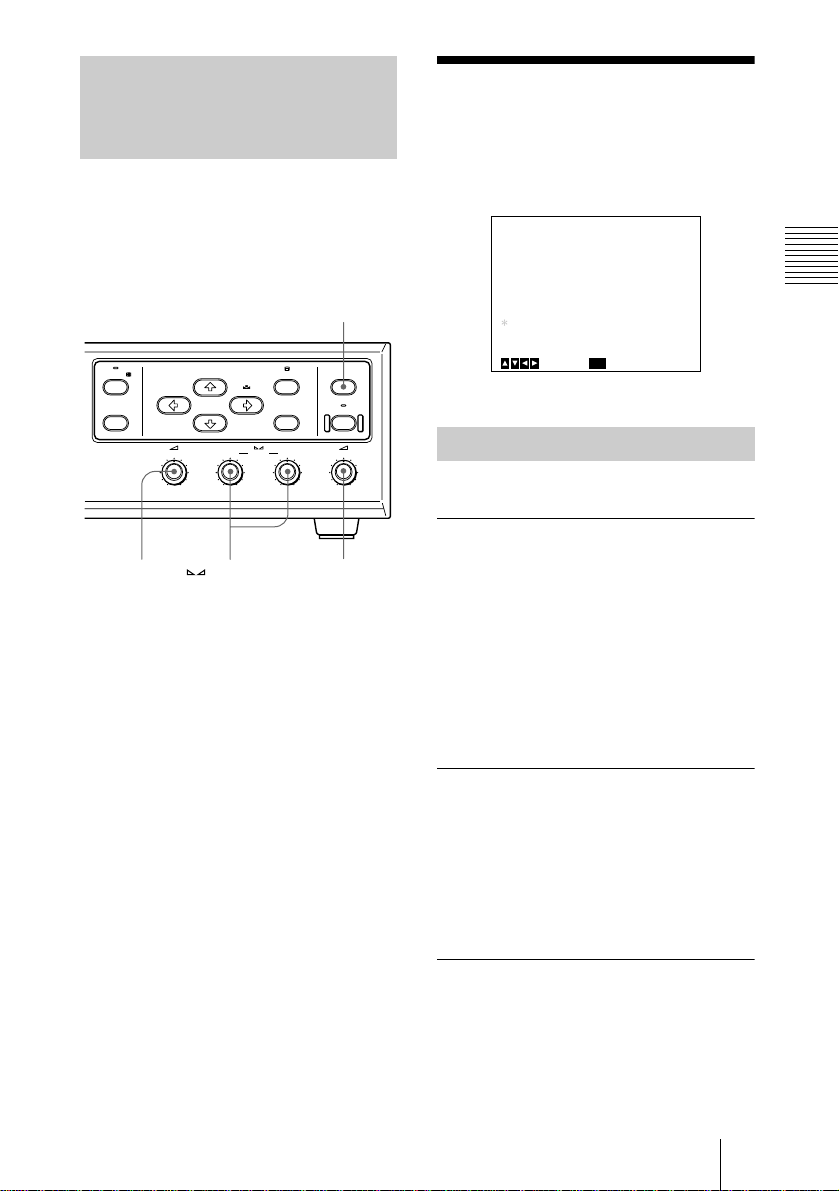
EXPOSURE Menu
The EXPOSURE menu is used to adjust the
items relating to exposure, such as gain and
shutter mode.
<EXPOSURE>
>GAIN
STEP
SHUTTER
AE SETUP
AE LEVEL
AE AREA1
AE AREA2
MENU
[A]
STEP
0dB
OFF
+_
0
MULTI
MULTI
BackSelect
Adjusting and Setting With Menus
2
GAIN
control
GAIN
0dB 24dB
BLUE controls
GAINRED BLUE AE LEVEL
– + – + – +
GAIN RED/
2
AE LEVEL
control
GAIN
Adjusts the video gain.
STEP
Select to set the video gain to the desired
level.
STEP
Adjust the gain level by turning the 2
GAIN control on the camera unit control.
The set value for STEP in the menu changes
to the adjusted level. The adjustable level is
within the range from 0 to 24 dB. You
cannot adjust it using the menu.
AGC
Automatically adjusts the gain according to
the brightness of the object to be shot
(Automatic gain control).
LIMIT
Selects the maximum gain level to be
adjusted to 6, 12, 18 or 24 dB.
HYPER
Increases the video gain to about 30 dB.
EXPOSURE Menu
13
GB

SHUTTER
Selects the electronic shutter modes.
OFF
Any electronic shutter mode does not
function.
STEP
Select to set the shutter speed to any of 4
steps in long-exposure mode and 15 steps in
high-speed mode.
SPEED
Sets the shutter speed.
To set the shutter speed
1 Select SPEED by pressing the V or v
button.
2 Display OFF by pressing the B and b
buttons simultaneously.
3 Press the B button to set the speed for
long-exposure mode, or press the b button
to set it for high-speed mode.
4 Each press changes the shutter speed.
VARIABLE
Use for fine adjustment of the video output
level in units of 1 frame (long exposure
mode) or in units of 1H (horizontal scanning
time: 63.56
DXC-C33P) (clear scan mode).
In long exposure mode, for example, if you
set to 10 frames (about 0.33 seconds), the
video signal produced during this set time is
output in the form of one complete frame at
intervals of about 0.33 seconds. These
pictures, which contain 10 frames of video
information, are much brighter than normal
one-frame images. This mode is useful for
shooting a poorly illuminated object in a
dark place.
The clear scan mode can be used for
shooting computer displays with reduced
horizontal bands appearing across the
display screen. Adjust the value while
observing the noise on the monitor screen so
that you can obtain the image with minimum
noise.
µ
s for DXC-C33, 64.00 µs for
To set the shutter speed
1 Select SPEED by pressing the V or v
button.
2 Display OFF by pressing the B and b
buttons simultaneously.
3 Press the B button to set the speed for
long-exposure mode, or press the b button
to set it for clear scan mode.
4 Each press changes the shutter speed.
To convert the value into the shutter
speed
Long-exposure mode
Example: When the value is set to 5 frames
5 × 1/30 = 0.1666 seconds (DXC-C33)
5 × 1/25 = 0.2000 seconds (DXC-C33P)
Clear scan mode
Example: When the value is set to 250H
DXC-C33:
µ
250 × 63.56
= 15924.9
s (1H) + 34.9 µs (constant)
µ
s = Approx. 0.016 seconds
DXC-C33P:
µ
250 × 64.00
= 16035.0
Note
s (1H) + 35.0 µs (constant)
µ
s = Approx. 0.016 seconds.
Do not use AGC, CCD-IRIS, ATW, AWB
DCC+ and DYNALATITUDE functions in
long exposure mode.
Set the gain level to 0 dB.
CCD-IRIS
Automatically adjusts the luminance level
for optimum output level. When incoming
light is excessive, this function
automatically adjusts the shutter speed to cut
exposure equivalent to up to 10 aperture
stops.
LIMIT
Sets the maximum shutter speed to be
adjusted to 1/250, 1/500, 1/1000, 1/2000,
1/4000, 1/10000, 1/20000,1/40000 or
1/100000.
SPEED
Sets the shutter speed.
GB
EXPOSURE Menu
14
KNOB
You can adjust the shutter speed and video
gain with the 2 AE LEVEL control on the
front of the camera control unit. With this
setting, GAIN is locked to STEP and the 2
GAIN control does not function.
When the RM-C950 remote control unit is
connected, you can use the IRIS control on
the remote control unit to adjust the shutter
speed and video gain.
AE SETUP
Adjusts the auto exposure focusing point
and selects the AE (Auto Exposure) window
when the camera is set to AGC or CCD IRIS
mode.
Note
The setting items for AE SETUP are
displayed only when GAIN is set to AGC or
SHUTTER is set to CCD-IRIS.
AE LEVEL
Adjust the auto exposure focusing point by
turning the 2 AE LEVEL control on the
camera control unit. The set value for AE
LEVEL in the menu changes to the adjusted
level. The adjustable level is within the
range from –127 to +127. You cannot adjust
it with the menu.
AE AREA1/AE AREA2
Selects the AE window when the camera is
set to AGC or CCD IRIS mode.
When a different AE window is set to each
of AE AREA 1 and 2, you can select either
by pressing the AE AREA SELECT button
on the camera control unit. The * mark
appears beside the selected AE AREA in the
menu. When the button is pressed while the
menu is not displayed, the selected AE
window is displayed on the monitor screen
for about a second.
MULTI: Divides the screen into 9 sections
and adjusts auto exposure according to the
luminance level in each section. Normally
set to this position.
LARGE, MID, SPOT and SLIT:
Displays the following AE windows and
adjusts auto exposure according to the
luminance level in each area. If the object
you are shooting is very small, you can see
it brighter with this setting to SPOT.
LARGE
MID
SLIT
SPOT
MANUAL: Sets the AE window manually
with the desired size and position on the
screen. Follow the steps below.
1 Select MANUAL and press the ENTER
button.
Cross cursor
Set Top-Left Point
Move Cross Cursor
MENU
Cancel
ENTER
Next
2 Move the cross cursor appearing at the
left top corner with the B, b, V or v
button to set the upper and left side size,
then press the ENTER button.
Set Bottom-Right Point
Move Cross Cursor
MENU
Cancel
ENTER
Next
BARS
Back
Cross cursor
Adjusting and Setting With Menus
EXPOSURE Menu
15
GB
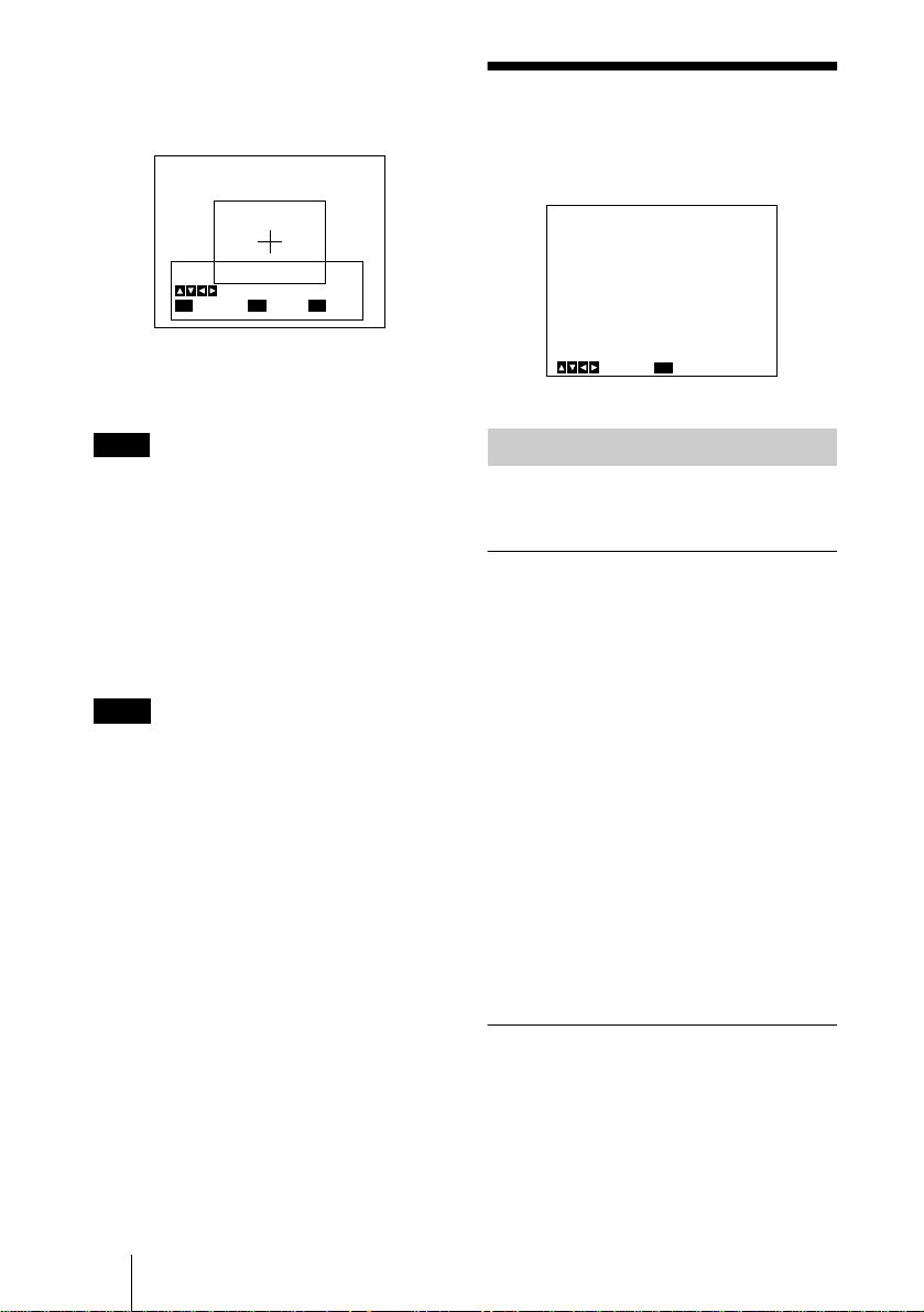
3 Move the cross cursor appearing at the
right bottom corner with the B, b, V or
v button to set the lower and right side
size, then press the ENTER button.
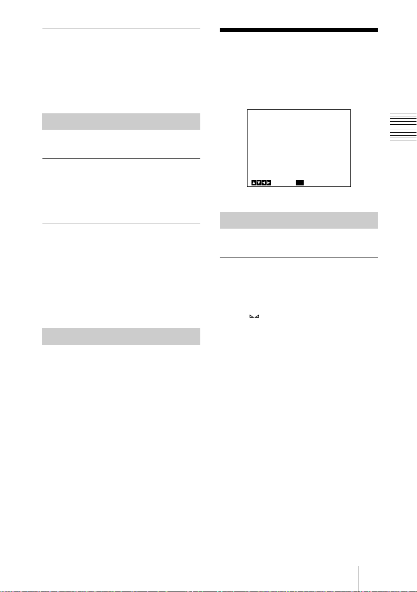
CONTRAST Menu
The CONTRAST menu is used to adjust the
contrast of the image.
Move Window
Move Cross Cursor
MENU
Cancel
ENTER
Fix
BARS
Back
4 Move the AE window to the desired
position with the B, b, V or v button,
then press the ENTER button.
Note
To cancel the setting before completing the
procedure, press the MENU button.
AE SPEED
Appears when you set AE AREA1 or 2 to an
option other than MULTI.
Sets auto exposure focusing speed in AGC
or CCD IRIS mode. Selects from MID
(normal speed), FAST (fast speed) and
SLOW (slow speed).
Note
If lens hunting occurs, adjust with AE
SPEED.
AE DETECT
Appears when you set AE AREA1 or 2 to an
option other than MULTI.
Selects the detection method of the
luminance level of the selected AE window.
AVERAGE: Selects to detect the average
luminance level of the whole AE window.
PEAK: Selects to detect the part with the
highest luminance level.
<CONTRAST>
>EFFECT
KNEE POINT
BLACK STRETCH
GAMMA
LEVEL
MASTER PEDESTAL
R. PEDESTAL
B. PEDESTAL
MENU
Select
Back
[A]
MANUAL
MID
+_
ON
+_
+_
+_
+_
0
0
0
0
0
EFFECT
Selects the setting suitable for the incident
luminance levels.
MANUAL
Selects KNEE POINT setting or BLACK
STRETCH.
KNEE POINT
Sets the knee point according to the
incoming light levels.
OFF: Knee processing does not function.
HIGH: Sets the knee point to the highest
level.
MID: Normally, select this position.
LOW: Sets the knee point to the lowest
level.
BLACK STRETCH
Adjusts the luminance of the dark portion of
the screen.
You can set the value within the range from
–10 to +10. The higher the setting, the
brighter the screen.
GB
CONTRAST Menu
16
DCC+ (Dynamic Contrast Control +)
When shooting a very bright object, the
whole screen may white out or a part of the
image may be colorless. This setting
minimizes these phenomena.
DYNALATITUDE
Adjusts the contrast according to the
luminance level of each picture element. The
setting is useful for shooting scenes mixed
with bright and dark parts.
You can set the level within the range from
–10 to +10.
WHITE BALANCE
Menu
The WHITE BALANCE menu is used to
adjust the white balance.
GAMMA
Activates gamma compensation.
OFF
Outputs the video signal linearly without
gamma compensation. Use this setting when
you want to produce images for image
processing or image analysis.
ON
Compensates the reproduction
characteristics of a cathode-ray tube of a
monitor to produce natural-tone image.
LEVEL
Adjusts gamma so that you can obtain
natural-tone image. Adjustable range is from
–10 to +10.
MASTER PEDESTAL
The pedestal levels of the G, B and R output
signals can be adjusted simultaneously.
Adjusts the darkness level of the black part
of the image. Use this function to bring out
details in heavily shaded areas. Use of a
waveform monitor allows easier adjustment.
The adjustable range is from –127 to +127.
The whole screen becomes whiter when you
adjust the level in the direction of +.
The whole screen becomes blacker when
you adjust the level in the direction of –.
Normally set to ±0.
R. (red) PEDESTAL, B. (blue)
PEDESTAL
Use these items to finely adjust the pedestal
level of each color. Adjust them while
watching the monitor screen. The items can
be finely adjusted within the range from
–127 to +127.
<WHITE BALANCE>
>MODE
R. PAINT
B. PAINT
AREA
MENU
Select Back
[A]
AWB
+_
+_
NORMAL
0
0
MODE
Selects the white balance modes.
AWB
Select to adjust the white balance
automatically (auto white balance).
R. (red) PAINT, B. (blue) PAINT
Use the GAIN RED or BLUE control on
the camera control unit to make fine
adjustments. Finely adjusts the red or blue in
the range from –100 to +100. Adjust them
while watching the monitor screen.
When adjusted, the set values change to the
adjusted levels.
For details, see “Adjusting the White
Balance” on page 26.
AREA
A detecting window appears on the monitor
screen. Normally set to NORMAL. If you
want to display the desired window, set to
MANUAL and follow the steps below.
1 Press the ENTER button.
2 Move the left top cross cursor with the B,
b, V or v button to set the upper and left
side size, and press the ENTER button.
3 Move the right bottom cross cursor with
the B, b, V or v button to set the lower and
right side size, and press the ENTER
button.
Adjusting and Setting With Menus
WHITE BALANCE Menu
17
GB

4 Move the window to the desired position
on the screen with the B, b, V or v button,
and press the ENTER button.
3200K
Selects for indoor shooting. (Color
temperature: 3200K)
ATW NORMAL/ATW WIDE
Activates auto-tracing white balance. The
white balance is automatically adjusted as
the color temperature changes.
These modes are suitable for shooting when
the light source changes.
Normally, set to ATW NORMAL.
The ATW WIDE setting can cope with a
wider range of color temperature changes.
R. PAINT, B. PAINT
Use the GAIN RED or BLUE controls
on the camera control unit to make fine
adjustments. Finely adjust the red or blue in
the range from –10 to +10. Adjust them
while watching the monitor screen. When
adjusted, the set values change to the
adjusted levels.
The adjusted values are stored in memory
separately from AWB values.
AREA
A detecting window appears on the monitor
screen. The setting procedure is the same as
that in AWB.
With NORMAL option, a detecting window
is displayed on the whole screen.
SPEED
Sets the focusing speed. You can select
SLOW (slow speed), MID (normal spe ed) or
FAST (fast speed).
5600K
Selects for outdoor shooting. (Color
temperature: 5600K)
MANUAL
Use for manual adjustment of white balance.
R. GAIN, B. GAIN
Use the GAIN RED or BLUE controls
on the camera control unit to adjust the red
or blue gain. The adjustable level is within
the range from – 127 to + 127. Adjust them
while watching the monitor screen. When
adjusted, the set values change to the
adjusted levels.
GB
WHITE BALANCE Menu
18
ENHANCER Menu
When you set DETAIL to TARGET,
TARGET COLOR appears. Specify the
colors you want to adjust.
The ENHANCER menu is used to adjust the
sharpness of the image outline and the color
tone (hue).
<ENHANCER>
>DETAIL
LEVEL
FREQUENCY
LINEAR MATRIX
MODE
MENU
Select Back
[A]
ALL
+_
MID
ALL
STANDARD
0
DETAIL
Enables or disables adjustment of the
sharpness of the image outline.
ALL
Enables adjustment of the sharpness of the
image outline.
LEVEL
Adjusts the level in the range from –127 to
+127.
The lower level decreases the sharpness of
the image outline and makes the image
softer.
The higher level increases the sharpness of
the image outline and makes the image
sharper.
When the RM-C950 remote control unit is
connected, this item is not adjusted with the
menu. Adjust it using the control on the RMC950.
FREQUENCY
Selects the frequency level with which the
image outline is adjusted from LOW (lower
frequency level), MID (middle frequency
level) or HIGH (higher frequency level).
Higher setting provides a sharper outline of
detailed images.
OFF
Disables adjustment of the sharpness of the
image outline.
LINEAR MATRIX
Processes an image with a color matrix to
change the chroma saturation and hue in
order to reproduce natural color.
ALL
Corrects the color to reproduce natural color.
MODE
Adjusts the color suitable for the subject.
STANDARD: Normally, select this setting.
R ENHANCE: Enhances the red.
B ENHANCE: Enhances the blue.
G ENHANCE: Enhances the green.
MANUAL: Adjusts each color finely. The
following options appear.
R. PAINT: Finely adjusts the red in the
range from –30 to +30.
G. PAINT: Finely adjusts the green in the
range from –30 to +30.
B. PAINT: Finely adjusts the blue in the
range from –30 to +30.
TARGET
Corrects the color for a specific color.
When you set LINEAR MATRIX to
TARGET, TARGET COLOR appears.
Specify the colors you want to adjust.
OFF
Color correction does not function. Use
when you want to process the image.
Adjusting and Setting With Menus
TARGET
Adjusts the image outline for a specific
color.
ENHANCER Menu
19
GB
TARGET COLOR
Select when adjusting DETAIL or LINEAR
MATRIX for a specific color.
This item is displayed only when you set
either DETAIL or LINEAR MATRIX to
TARGET.
ALL
Adjusts DETAIL or LINEAR MATRIX for
the whole image. Normally, set to this
position.
IN
Adjusts DETAIL or LINEAR MATRIX for
a specific color.
RANGE
Finely adjusts the area in the range from –10
to +10.
To specify a color
1 Press the ENTER button.
2 Move the cross cursor ( ) appearing in
the center of the screen to the desired
color with the B, b, V or v button so that
the cross cursor square covers the desired
color.
You can adjust the color indicated by the
cross cursor ( ).
3 Press the ENTER button.
The screen returns to the menu display. To
cancel the setting before completing the
procedure, press the MENU button.
OUT
Adjusts DETAIL or LINEAR MATRIX for
colors other than a specified color.
RANGE
Finely adjusts the area in the range from –10
to +10.
When you select OUT, then set the color
with the procedure in “To specify a color,”
you can adjust DETAIL or LINEAR
MATRIX for colors other than that indicated
by the cross cursor ( ).
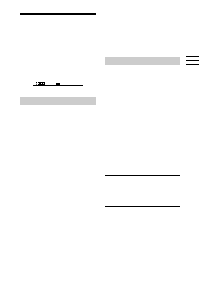
GENERAL Menu
The GENERAL menu is used to set the
general items.
<GENERAL>
>CCD MODE
SHADING COMP.
FS/TRIG IN
NEGA
FLICKER CANCELLER
MENU
Select Back
CCD MODE
Selects the CCD read-out mode.
FIELD
Accumulates charges in field units.
Use to shoot a moving object.
FRAME
Accumulates charges in frame units.
Provides the image with the highest possible
vertical resolution. Use to shoot a still
object.
SHADING COMP. (Shading
Compensation)
Eliminates green or magenta color which
may appear at the top or bottom of the
screen, when the camera is used with an
optical instrument.
OFF
Color elimination does not function.
ON
If green or magenta color appears at the top
or bottom of the screen when the camera is
attached to a microscope, etc., select this
setting.
[A]
FIELD
OFF
OFF
OFF
OFF
GB
GENERAL Menu
20
LEVEL
Adjusts the level within the range from –127
to +127. Adjust while watching the screen so
that the color is eliminated.
+: Green at the top and magenta at the
bottom will be eliminated.
–: Magenta at the top and green at the
bottom will be eliminated.
FS/TRIG IN (Foot Switch/
Target Input)
Selects the input signal from the FS/
TRIG IN connector.
NEGA
Reverses the output image to negative/
positive.
OFF
Outputs the image normally.
ON
Outputs the image reversed to negative/
positive.
FLICKER CANCELLER
Adjusting and Setting With Menus
OFF
Select when neither a slave unit nor foot
switch is connected.
FS
Select when an optional foot switch is
connected. Turning on or off the foot switch
outputs a freeze picture and an image
currently shot, alternately.
TRIGGER
Select when a slave unit is connected to
synchronize the camera with a stroboscope.
Each time a trigger pulse is input, the freeze
picture changes.
When TRIGGER is selected, you cannot
output an image as a freeze picture with the
FREEZE button on the camera control
unit.
POLARITY
Selects the same polarity as that of the pulse
signal input.
: Falling edge
: Rising edge
Note
When FS/TRIG IN is set to TRIGGER or
FS, AGC, CCD IRIS, ATW, AWB, DCC+
and DYNALATITUDE modes do not
function.
When using the camera in a 50 Hz lighting
area (DXC-C33) or in a 60 Hz lighting area
(DXC-C33P), you can obtain images with
less flicker under fluorescent light even
when SH UT TER is se t t o C CD IRIS o r O FF .
Set this item to OFF when you want to set
NEGA to ON.
OFF
Disables the FLICKER CANCELLER
function.
ON
Reduces flicker under fluorescent light.
GENERAL Menu
21
GB
SYSTEM Menu
The SYSTEM menu is used to set the items
relating to the system of the camera and
selection of output signals.
For the timing chart of the WEN pulse signal
for each setting, see page 42.
POLARITY
Selects the polarity of the pulse signal.
: Negative
: Positive
<SYSTEM>
>BAUD RATE
D-SUB VIDEO
D-SUB SYNC
RGB SYNC
EXT SYNC
Select Back
MENU
[A]
9600
VBS
C.SYNC
G
IN
BAUD RATE
Switches the baud rate of the REMOTE
connector.
Sets to any of 19200, 9600, 4800, 2400
and 1200.
Set to 9600 when the RM-C950 remote
control unit is connected.
D-SUB VIDEO
Selects the VBS or Y/C signal output from
the RGB/SYNC connector (D-sub 9pin).
D-SUB SYNC
Selects the sync signal output from the
RGB/SYNC connector (D-sub 9-pin).
RGB SYNC
Adds a sync signal to the G signal or R, G
and B signals output from the RGB/
SYNC connector.
OFF
No sync signal is added to an output signal.
G
Adds a sync signal to the G signal output
from the RGB/SYNC connector.
RGB
Adds sync signals to the G, B and R signals
output from the RGB/SYNC
connector.
EXT SYNC
Switches the input and output of the EXT
SYNC (HD, VD/SYNC) jacks (BNC type)
and selects the output signal.
IN
Functions as the input jack.
C. SYNC
Outputs the composite sync signal.
WEN-ODD/WEN-EVEN/WEN-NORM
Outputs the WEN signal. When connecting
peripheral equipment, the signal is used as
trigger pulse output to the equipment.
Switching WEN-ODD or WEN-EVEN
provides a different pulse signal phase.
GB
SYSTEM Menu
22
When an external sync signal (VBS signal)
is input, the following items appear:
Adjusts the horizontal phase and SC
(subcarrier) phase to synchronize the camera
operation with the reference signal.
H. PHASE
Adjusts the horizontal phase within the
range from –20 to +127.
SC. PHASE ROUGH
Roughly adjusts the subcarrier phase by
setting to 0° or 180°.
SCENE FILE Menu
SC. PHASE FINE
Finely adjusts the subcarrier phase within
the range from –127 to +127.
When an external sync signal (HD/VD
signal) is input, the following items appear:
Adjusts the horizontal phase to synchronize
the camera operation with the reference
signal.
H. PHASE
Adjust the level within the range from –20 to
+127.
Note
Turn on the external sync signal generator
after all equipment is switched on.
OUT
Functions as the output jack.
SIGNAL
Selects the output signal from the EXT
SYNC jacks.
HD/VD: Outputs the HD/VD signal.
C. SYNC: Outputs the composite sync
signal.
The SCENE FILE is used to set the preset
menu settings.
The camera has two memory files (A or B)
for storing the menu settings. You can store
a different type of setting into each file, and
switch to the file most suitable for the
shooting conditions quickly. The currently
selected memory file is shown in the upper
right corner of the on-screen menu.
<SCENE FILE>
>FILE SELECT
LOAD
Select Back
MENU
[A]
A
FILE SELECT
Selects the file A or B.
LOAD
Selects the setting to be stored into the file
you select with FILE SELECT, and stores
the setting.
Adjusting and Setting With Menus
STANDARD: Suitable for a camera used as
a permanent fixture.
MICROSCOPE: Suitable for a camera for
a microscope.
FULL AUTO: Automatically adjusts
settings.
STROBE: Suitable for stroboscopic
shooting.
FILE B (or A): When copying the settings
between two files.
SCENE FILE Menu
23
GB

To store the setting
1 Select A or B into which the setting is
stored in the FILE SELECT setting.
2 Press the V or v button to select LOAD.
3 Press the B or b button to select the
desired setting to be stored, and press the
ENTER button.
“Overwrite OK?” appears.
4 Press the ENTER button.
If you do not want to store the setting,
press the MENU button.
GB
SCENE FILE Menu
24
Operation
B
Shooting
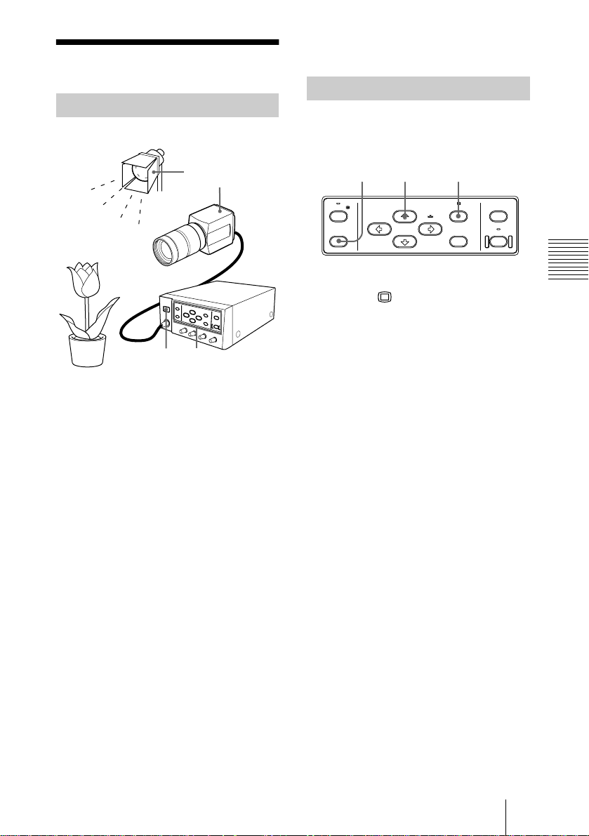
Basic Shooting Procedure
8
Start shooting.
Adjusting the Black Balance
Adjust the black balance first, after turning
on the power of your camera.
4
5
1 3,6,7
1
Press down the ! (power) switch on
the camera control unit to turn on the
power.
The power indicator lights in green.
2
Turn on the powers of the connected
devices.
3
Adjust the black balance.
For details, see “Adjusting the Black
Balance” on the right column.
4
Illuminate an object with proper
lighting.
5
Aim the camera to the object and
adjust the iris, focus and zoom.
132
FREEZE
BARS
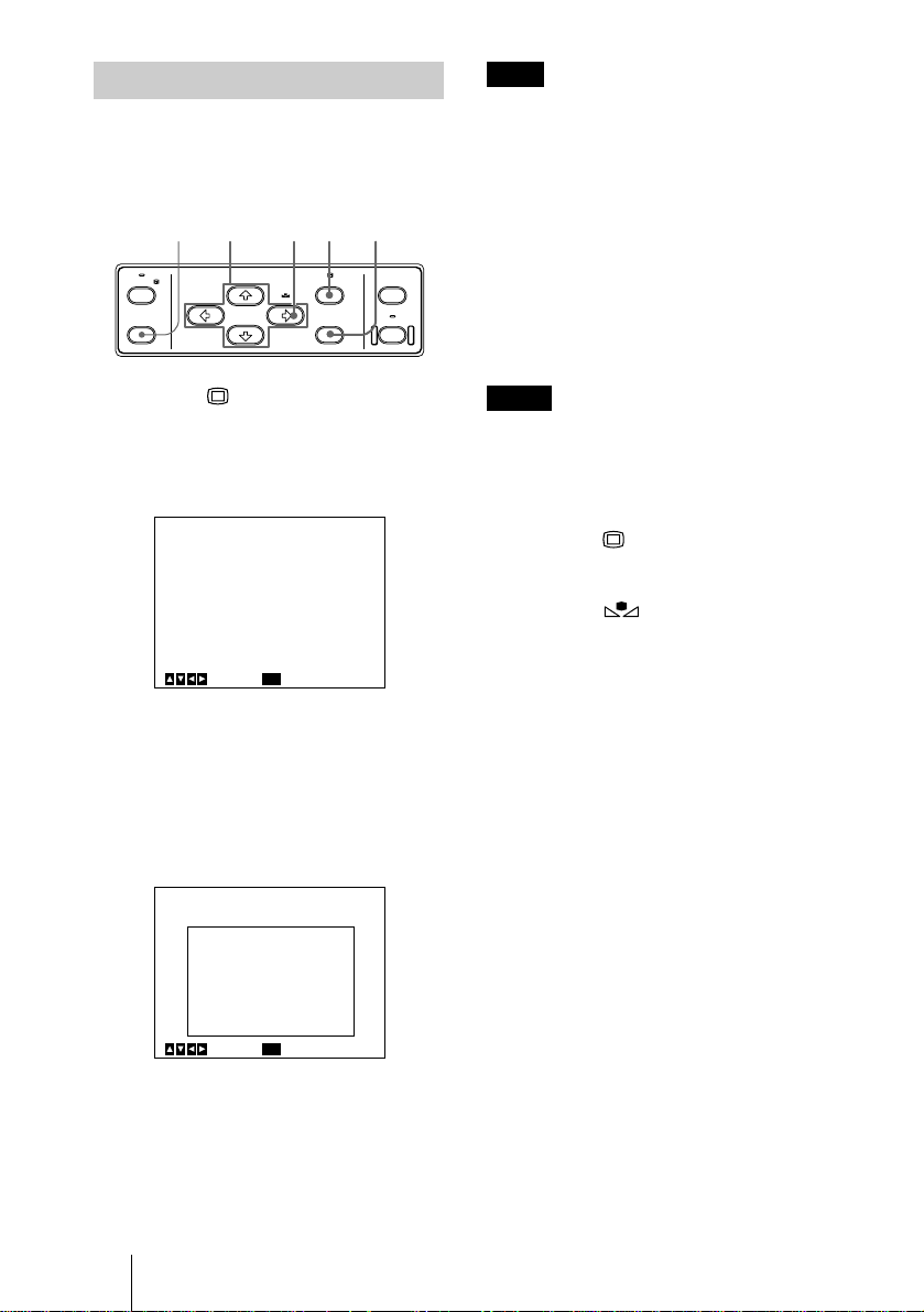
1
If any menu is displayed on the screen,
BLACK MENU
SCENE FILE
SELECT
WHITE
press the MENU button to remove
it.
2
If a color bar signal is displayed on the
screen, press the BARS button to
remove it.
3
Press the BLACK button.
Close the iris before pressing the button.
The black balance is automatically
adjusted.
While adjusting, the bars are displayed.
When the adjustment is completed, the
message “BLACK: OK” appears on the
screen.
Black balance adjustment errors
If the black balance adjustment is not
successful, the message “BLACK: NG”
appears on the screen. If this happens, take
the necessary measures and perform steps 1
through 3 again.
For details, see “List of Messages” on page
41.
AE AREA
SELECT
ENTER LOCK
Operation
6
Adjust the white balance.
For details, see “Adjusting the White
Balance” on page 26.
7
Adjust the settings as required.
For details, see “Adjusting and Setting
With Menus” on page 11.
Shooting
25
GB
Adjusting the White Balance
Each time the lighting condition changes, be
sure to adjust the white balance so that
optimum color reproduction is obtained.
BARS
button
FREEZE
BARS
1
Press the MENU button to display
BLACK MENU
SCENE FILE
SELECT
WHITE
the MAIN menu.
2
Select the WHITE BALANCE menu,
and set MODE to AWB.
<WHITE BALANCE>
>MODE
R. PAINT
B. PAINT
AREA
MENU
Select Back
For menu operation, see “Operation
Through Menus” on page 12.
3
Select AREA with the V or v button
and then set it to NORMAL with the B
or b button.
A detecting window appears.
ENTER LOCK
[A]
AWB
+_
+_
NORMAL
22,3 8 1,7
AE AREA
SELECT
0
0
Note
If a color bar signal is displayed on the
screen, press the BARS button to turn it off.
5
Set the lens iris control to the
appropriate opening value.
6
Place a white object (white pattern,
white cloth, etc.) under the same light
condition as that falling on the object
to be shot, then zoom in on the white
object to fill the detecting window on
the screen.
Notes
• Do not include highly reflective objects in
the picture.
• Always shoot the image under suitable
lighting conditions.
7
Press the MENU button twice to
remove the menu.
8
Press the WHITE button.
During adjustment the bars appear. The
message “WHITE: OK” appears on the
screen when the adjustment is done.
The adjusted white level is
automatically stored in memory and
remains even if the power of the camera
is turned off.
To shoot under the same conditions, the
stored white balance is recalled by
setting MODE to AWB in the WHITE
BALANCE menu.
<WHITE BALANCE>
MODE
R. PAINT
B. PAINT
>AREA
MENU
Select Back
For more details, refer to “WHITE
BALANCE Menu” on page 17.
4
Display the camera image on the
monitor screen.
GB
Shooting
26
[A]
AWB
+_
+_
NORMAL
0
0
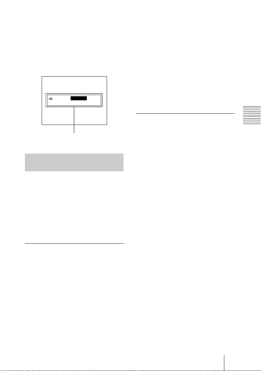
White balance adjustment errors
If the auto white balance adjustment is not
successful, an error message appears on the
screen. If this happens, take the necessary
measures and perform steps 1 through 8
again.
For more details, see “List of Messages” on
page 41.
WHITE: NG
XXXXX
Error message
Adjusting the Picture Tone in
a Multi-Camera System
When configuring a multi-camera system,
adjust all cameras to prevent camera-tocamera variations in picture tone.
Before making the adjustments outlined
below, input the same sync signal to all
cameras.
For connections, see “Connecting Two or
More Cameras — Multi-Camera System” on
page 34.
Connecting the cameras to video
equipment with phase indication
capability
When connecting to a special-effects
generator, a chroma-key unit, or other video
equipment with phase indication capability,
the basic adjustment procedure is as follows:
1
Turn on the phase indication
capability of the connected video
equipment.
For more details, see “SYSTEM Menu”
on page 22.
3
Select SC. PHASE from EXT SYNC
in the SYSTEM menu, and adjust the
subcarrier phase.
First adjust the subcarrier phase roughly
with SC. PHASE ROUGH set to 0° and
180°, then adjust it finely using SC.
PHASE FINE.
For more details, refer to the instruction
manual of the connect ed vid eo
equipment with phase indication
capability.
Connecting the cameras to video
equipment without phase
indication capability
Use one of the cameras as a reference
camera and adjust the other cameras to the
reference camera one by one.
1
Adjust the horizontal phase. Select
H. PHASE from EXT SYNC in the
SYSTEM menu, and adjust so that the
reference video signal and the output
signal have the same horizontal sync
phase. Use a waveform monitor or an
oscilloscope to check the phase.
2
Adjust the subcarrier phase. Select
SC. PHASE from EXT SYNC in the
SYSTEM menu.
First adjust the subcarrier phase roughly
with SC. PHASE ROUGH set to 0° and
180°, then adjust it finely using SC.
PHASE FINE so that the reference video
signal and the output video signal have
the same subcarrier phase. Use a
vectorscope or the wiping function of a
special-effects generator to display the
images of both the reference camera and
the camera to be adjusted
simultaneously on the screen.
Operation
2
Select H. PHASE from EXT SYNC in
the SYSTEM menu, and adjust the
horizontal phase.
Shooting
27
GB
Installation and Connections
B
Installation
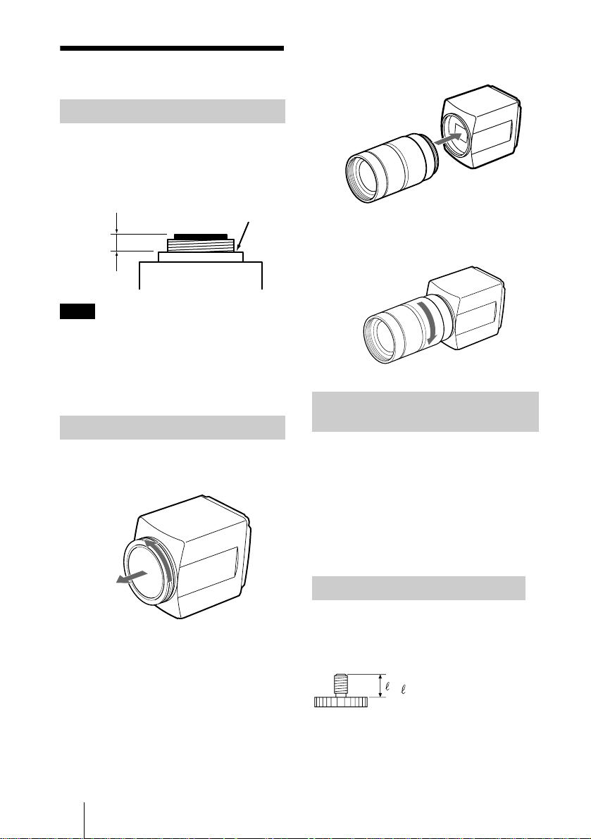
Applicable Lens
C-mount lenses with the following lens
mount surface can be attached to the camera
head.
Lens mount
surface
4.3 mm
or less
Note
Be sure to use a lens whose projected part
from the lens mount surface is less than 4.3
mm. Mounting the lens with a projected part
greater than 4.3 mm may damage the
internal mechanism of the camera head.
Mounting the Lens
1
Remove the lens mount cap of the
camera head.
2
Align the threaded portion of the lens
mount with that of the camera mount.
3
Slowly rotate the lens clockwise to fix
the lens to the camera head tightly.
Mounting a Microscope
Adaptor
To attach the camera to a microscope or a
surgical microscope, it is necessary to attach
an appropriate adaptor.
The mounting procedure is the same as that
of the lenses.
GB
28
For details, refer to the instruction manual
for the adaptor to be used.
Mounting on a Tripod
Attach the supplied tripod adaptor to the
camera head, then mount the adaptor on a
tripod using the following mounting screw:
U1/4″, 20 UNC
= 4.5 mm ± 0.2 mm
(ISO standard)
Installation
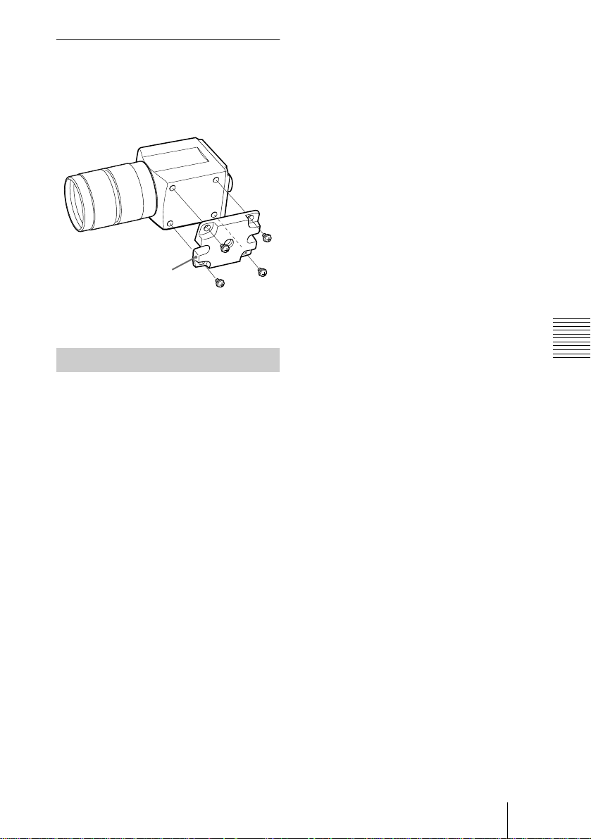
To attach the supplied tripod
adaptor
Attach the supplied tripod to the four M3
screw holes on the bottom of the camera
head with the supplied four M3 screws.
Tripod adaptor
(supplied)
M3 screws (4)
(supplied)
Attaching to a Wall or Ceiling
To mount the camera head on a wall or
ceiling, attach the camera head with the
tripod adaptor to the mounting bracket or
suspension bracket using the appropriate
screw (U1/4″, 20 UNC) that fits the tripod
hole of the adaptor.
Installation and Connections
Installation
29
GB
Connections
Connecting Between the
Camera Head and Camera
Control Unit
Connect the camera cable connector on the
camera head with the CAMERA connector
on the camera control unit using the CCMC20P05/10/30 camera cable (not supplied).
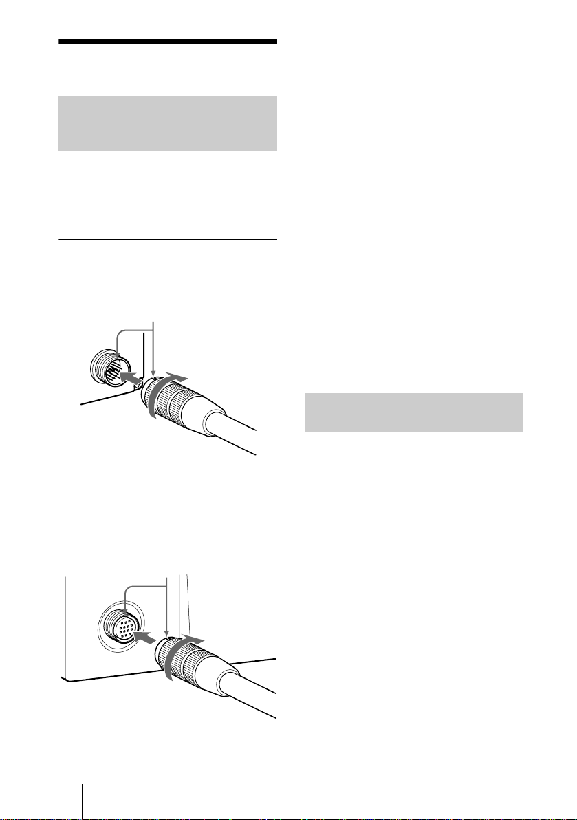
To connect the camera cable to the
camera head
1 Align the projection of the camera cable
connector with the notch on the connector
of the camera cable to insert.
Connector
(female)
2 Turn the
connector ring
to tighten.
Notes on connection between the
camera head and camera control unit
• Turn off the power supply for all
equipment before making any connection.
Be sure to turn off the camera when you
connect or disconnect the camera cable.
Connecting/disconnecting a cable while
the power is on may damage the camera.
• Be sure to connect the camera head and
camera control unit with the camera cable
before you turn on/off the power of the
camera.
• Make correct connection with the male
and female sides of the connectors on the
camera cable. Incorrect connection may
cause damage to the camera.
• Insert the connectors of the cables
properly. Loose connection often
generates noise. When pulling out a cable,
be sure to pull it out by the connector, not
the cable itself.
• The camera control unit is designed to be
used with this camera head. Use both
together for optimum picture quality.
Connecting the AC Power
Cord
Connect the supplied AC power cord to the
- AC IN socket on the camera control unit.
To connect the camera cable to the
camera control unit
1 Align the projection of the CAMERA
connector with the notch on the connector
of the camera cable to insert.
CAMERA
Connector
(male)
2 Turn the
connector ring
to tighten.
GB
Connections
30
 Loading...