

Page 1
Color Video Camera
Technical Manual
A-E4V-100-11(1)
EVI-D80N/P/D90N/P
2011 Sony Corporation
Page 2

Table of Contents
Aegis Electronic Group
www.aegiselect.com
For More Information Please Call Aegis Electronic Group, Inc. * (888) 687-6877 Phone * [email protected] * http://www.aegis-elec.com
Features ............................................................................. 3
Connection ........................................................................ 4
Locations of Controls .......................................................5
Basic Functions .................................................................8
Overview of Functions ..................................................................... 8
Initial Settings and Position Preset ........................................... 15
Mode Condition .............................................................................. 16
Command List .................................................................21
VISCA1) RS-232C Commands ....................................................... 21
EVI-D80N/D80P/D90N/D90P Commands .............................. 29
D70 Mode ........................................................................43
Overview ........................................................................................... 43
Switching the Mode ...................................................................... 43
Accepting or Sending Back Commands ................................. 44
Translating Parameters ................................................................. 45
Specifications ................................................................. 47
Precautions .....................................................................50
2
Page 3

An EX-view HAD™ CCD features 380,000 (NTSC) or
Aegis Electronic Group
www.aegiselect.com
For More Information Please Call Aegis Electronic Group, Inc. * (888) 687-6877 Phone * [email protected] * http://www.aegis-elec.com
440,000(PAL) effective picture elements and
highsensitivity shooting. The minimum illumination
required is 0.7 lx (1/60 sec. (NTSC), 1/50 sec. (PAL),
ICR OFF). (EVI-D90N/D90P)
A CCD fe
effective picture elements and high-sensitivity
shooting. The minimum illumination required is 0.4
lx (1/60 sec. (NTSC), 1/50 sec. (PAL)). (EVI-D80N/
D80P)
The EVI-D90N/D90P a
zoom lens with 28× optical zoom and F1.35 aperture.
The EVI-D80N/D80P a
zoom lens with 18× optical zoom.
A newly-de
resolution images.
By adoptin
you can see the optimised shooting image which
incorporates bright and dark subjects at the same
time. (EVI-D90N/D90P)
3D Low-noi
light environments using the Noise Reduction
function.
Adopts th
VISCA camera protocol in external communication.
It is possible to operate from long distances by using
both RS-232C and RS-422.
You can
functions of high-speed and wide range pan/tilt
action and vertical image flip.
You can
the camera and also to select panning, tilting and
zooming from the setting menu.
You can
camera status into the camera.
atures 380,000 (NTSC) or 440,000 (PAL)
re equipped with a bright
re equipped with a bright
veloped Processor provides high
g its wide and dynamic range functions,
se images can be obtained even in low-
e industry standard RS-232C interface of
install the camera on ceilings due to the
use the infrared remote commander to set
store up to 6 kinds of camera direction and
Features
3
Page 4
Connection
Aegis Electronic Group
www.aegiselect.com
For More Information Please Call Aegis Electronic Group, Inc. * (888) 687-6877 Phone * [email protected] * http://www.aegis-elec.com
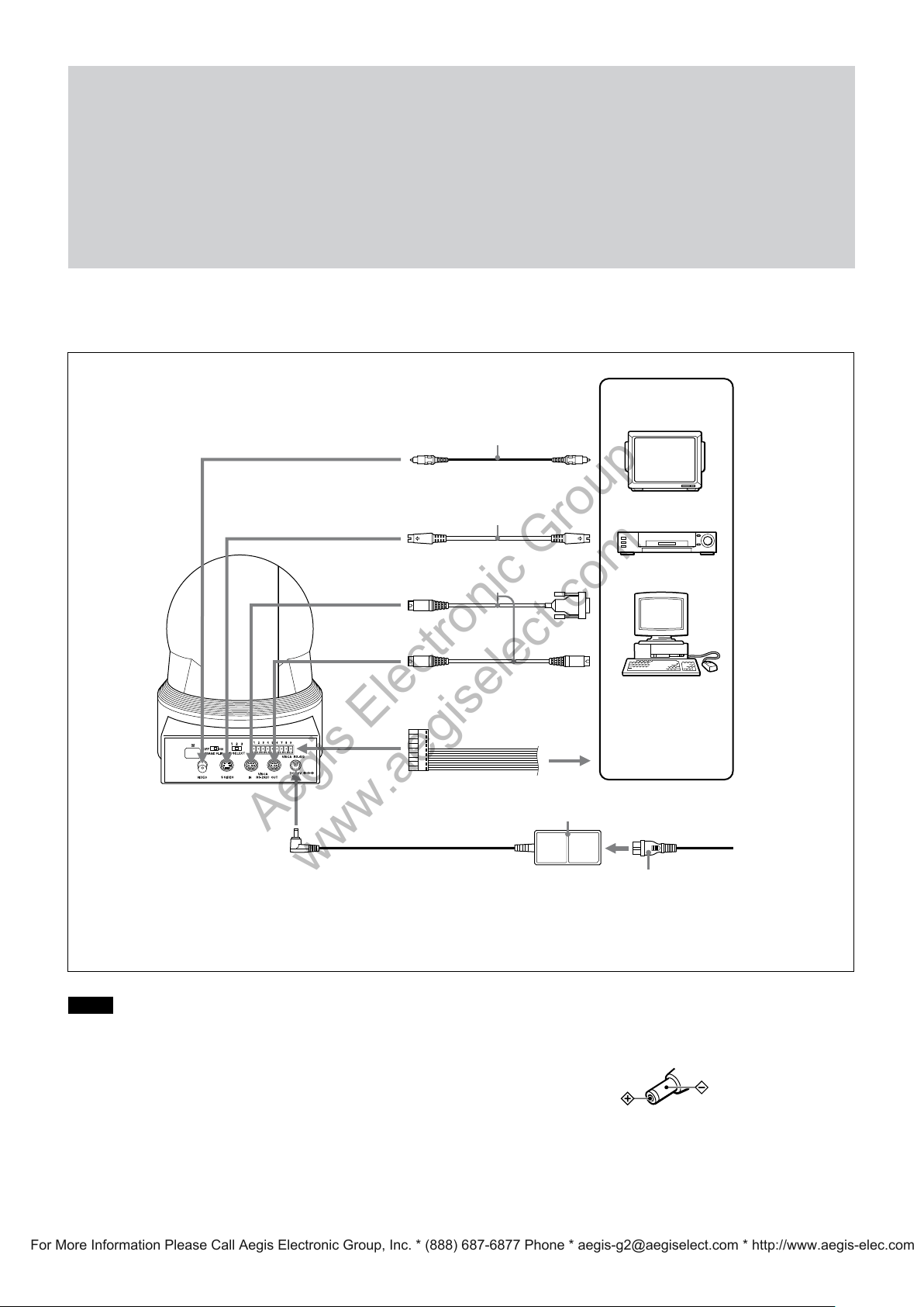
to VIDEO
to S VIDEO
to VISCA IN
to VISCA OUT
to DC 12V
Video cable
(not supplied)
S-Video cable (not supplied)
VISCA cable (not supplied)
to VISCA RS-422
2)
to Video
input
to S-Video
input
1)
to RS-232C
To VISCA IN of other
EVI-D80N/D80P/
D90N/D90P (when
connecting to more
than one camera)
AC power adaptor
(supplied)
Computer, TV or VCR
with a video input
jack
to AC outlet
Power cord (supplied)
1) When the camera is connected to a computer with a VISCA cable (cross type, RS-232C), you can operate the
camera with the computer. To obtain a cable, consult the dealer where you bought your camera.
2) For details on how to connect using VISCA RS-422, see page 26.
Notes
You cannot connect your Color Video Camera to a
computer that is not equipped with either video input
Use onl
supplied with the unit. Do not use any other AC
power adaptor.
y the AC power adaptor (JEITA type4)
or an S-Video input connector. You might not be able
to use your existing computer with your Color Video
Camera unless you provide the computer with a
video capture board and/or software. Consult your
computer dealer or manufacturer for details.
Do not make VISCA RS-232C and RS-422
Polarity of the plug
connections at the same time, as this may cause
malfunctions.
4
Page 5
Locations of Controls
Aegis Electronic Group
www.aegiselect.com
For More Information Please Call Aegis Electronic Group, Inc. * (888) 687-6877 Phone * [email protected] * http://www.aegis-elec.com
Main Unit
Front Rear
Bottom
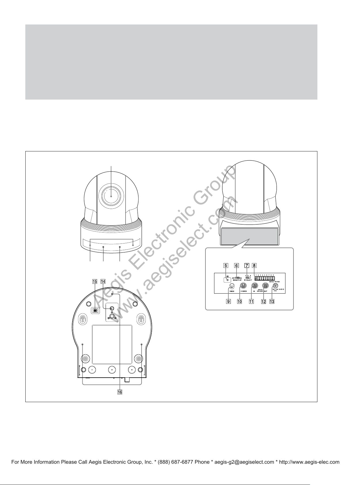
Lens
Remote sensors
POWER lamp
STANDBY lamp
etai
For d
and STANDBY lamp, see “LED Status” on page 42.
Remote sensors
led information on LED status of the POWER lamp
(Continued)
5
Page 6
6
Locations of Controls
12345
Aegis Electronic Group
www.aegiselect.com
For More Information Please Call Aegis Electronic Group, Inc. * (888) 687-6877 Phone * [email protected] * http://www.aegis-elec.com
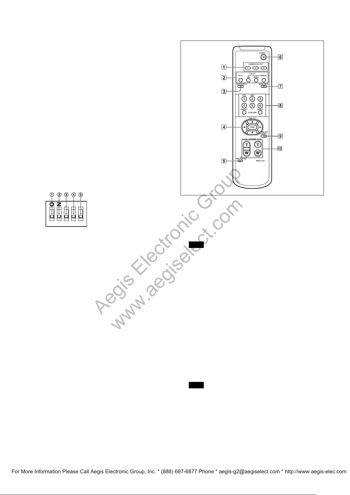
IMAGE FLIP switch
Flips the image upside down. Normally set this to OFF when
you use the camera. When the camera is attached to the
ceiling, set this to ON. Before you set the IMAGE FLIP
switch, turn off the unit (or set to standby mode) and then,
turn the power on by connecting the power adaptor, by
VISCA control or the remote commander. When you switch
this, the preset setting is returned to the initial setting. It
takes about 7 to 14 seconds for the image displayed to
respond to the setting change.
IR SELECT switch
VISCA RS-422 connect
VIDEO(output) connector
S VIDEO(output) connect
VISCA IN connector
VISCA OUT c
DC 12V connec
Tripod scr
BOTTOM switches
onnector
tor
ew hole
or
or
Remote Commander
D70 mode switch
Set to ON to use the VISCA command for EVI-D70/
D70P.
IR OUT swit
Set to O
are transmitted from the infrared remote commander
via the VISCA IN connector (page 25), or set it to OFF
to disable the output.
RS-232C/RS-422 select switch
Set to ON
VISCA command via the RS-422 interface. To change
the mode, turn off the camera (not including standby
mode) first, set the switch and then turn on the camera
again. Mode switching is not possible while the camera
is turned on.
Baud rate select switch
Set to ON
change the mode, turn off the camera (not including
standby mode) first, set the switch and then turn
on the camera again. The mode cannot be switched
while the camera is turned on.
Switch 5 (Not used)
Be sure
ch
N to enable output of the receiver signals, which
to operate colour video camera using the
for 38,400 bps or OFF for 9,600 bps. To
to set this switch to OFF.
CAMERA SELECT buttons
Press the button corresponding to the camera you want to
operate with the Remote Commander.
The camera number can be set using the IR SELECT switch
on the rear of the camera.
Note
If two or more cameras are adjacent and have the same
camera number, they are operated simultaneously with the
same Remote Commander. When you install the cameras
close to each other, set different camera numbers.
For the camera number setting, see “Operating Multiple
Cameras with the Remote Commander” described in the
Operating Instructions supplied with the camera.
FOCUS buttons
r focus adjustment.
Used fo
Press the AUTO button to adjust the focus automatically. To
adjust the focus manually, press the MANUAL button, and
adjust it with the FAR and NEAR buttons.
DATA SCREEN button
Press thi
turn off the menu. If you press the button when a lower-level
menu is selected, the display goes back to a higher-level
menu.
Pan/tilt operations are disabled when the menu is displayed.
s button to display the main menu. Press it again to
Note
Ceiling bracket mounting screw holes
Page 7

PAN-TILT buttons
Aegis Electronic Group
www.aegiselect.com
For More Information Please Call Aegis Electronic Group, Inc. * (888) 687-6877 Phone * [email protected] * http://www.aegis-elec.com
Press the arrow buttons to perform panning and tilting.
Press the HOME button to face the camera back to the front.
When the menu is displayed, use or to select the menu
items a
nd or to change the set values. The selected
setting
menu is displayed, by pressing the HOME button
when the main menu is displayed.
The Pan/tilt speed will slow down when the camera is
zoomed, in order to allow precise positioning.
L/R DIRECTION SET button
Hold do
the direction of the camera movement opposite to that
indicated by the arrow of the / buttons.
To reset
STD button while holding down this button.
POWER switch
Press thi
is connected to an AC outlet.
BACK LIGHT button
Press thi
Press it again to disable the backlight compensation.
wn this button and press the REV button to change
the direction of the camera movement, press the
s button to turn on/off the camera when the camera
s button to enable the backlight compensation.
Locations of Controls
POSITION buttons
Hold down
store the current camera direction, zooming, focus
adjustment and backlight compensation in the memory of
the pressed number button.
To erase the memory contents, hold down the RESET
button and press button 1 to 6.
Note
These buttons do not function when the menu is displayed.
PAN-TILT RESET button
Press thi
ZOOM buttons
Use the
to zoom quickly.
Press the T (telephoto) side of the button to zoom in, and
the W (wide angle) side to zoom out
the PRESET button and press button 1 to 6 to
s button to reset the pan/tilt position.
SLOW button to zoom slowly, and the FAST button
7
Page 8
Basic Functions
Aegis Electronic Group
www.aegiselect.com
For More Information Please Call Aegis Electronic Group, Inc. * (888) 687-6877 Phone * [email protected] * http://www.aegis-elec.com
Overview of Functions
Zoom
EVI-D80N/P:
The camera employs a 18× optical zoom lens
combined with a digital zoom function; this camera
allows you to zoom up to 216×.
• Optical 18×, f = 4.1 mm to 73.8 mm (F 1.4 to F 3.0)
The horizontal angle of view is approximately 48.0
degrees (wide end) to 2.8 degrees (tele end).
Digital Zoom enlarges the center of the subject by
expanding each image in both the vertical and
horizontal directions. When 216× zoom is used, the
number of effective picture elements in each direction
reduces to 1/12 and the overall resolution deteriorates.
EVI-D90N/P:
The camera
combined with a digital zoom function; this camera
allows you to zoom up to 336×.
Optical
The horizontal angle of view is approximately 55.8
degrees (wide end) to 2.1 degrees (tele end).
Digital Zoom enlarges the center of the subject by
expanding each image in both the vertical and
horizontal directions. When 336× zoom is used, the
number of effective picture elements in each direction
reduces to 1/12 and the overall resolution deteriorates.
You can activate the zoom in the following two ways
By pressing the ZOOM b
Commander
Using a VISCA Command
Us
Using Variable Mode
Th
Direct Mode
Setting th
movement to the designated position.
employs a 28× optical zoom lens
28×, f = 3.5 mm to 98.0 mm (F 1.35 to F 3.7)
uttons on the Remote
ing Standard Mode
ere are
eight levels of zoom speed.
e zoom position enables quick
Digital Zoom ON/OFF
In these standard and variable Speed Modes, it is
necessary to send Stop Command to stop the zoom
operation.
Focus
Focus has the following modes, all of which can be set
using VISCA Commands.
Auto Focus Mode
The minimum f
wide end and 800 mm (EVI-D80N/P), 1500 mm
(EVI-D90N/P) at the optical tele end, and is
independent of the digital zoom. The Auto Focus
(AF) function automatically adjusts the focus
position to maximise the high frequency content of
the picture in a center measurement area, taking into
consideration the high luminance and strong
contrast components.
- Normal AF Mode
This is th
- Interval AF Mode
The mode u
particular intervals. The time intervals for AF
movements and for the timing of the stops can be
set in one-second increments using the Set Time
Command. The initial value for both is set to five
seconds.
- Zoom Trigger Mode
When the
buttons
value (initially set at 5 seconds) becomes that for
AF Mode. Then, it stops.
AF sensitivity can be set to either Normal or LOW.
- Normal
Reaches th
when shooting a subject that moves frequently.
Usually, this is the most appropriate mode.
- LOW
Improves
lighting level is low, the AF function does not take
effect, even though the brightness varies,
contribut
on the Remote Commander, the pre-set
ocus distance is 10 mm at the optical
e normal mode for AF operations.
sed for AF movements carried out at
zoom is changed with the ZOOM
e highest focus speed quickly. Use this
the stability of the focus. When the
ing to a stable image.
8
Page 9

Basic Functions
Aegis Electronic Group
www.aegiselect.com
For More Information Please Call Aegis Electronic Group, Inc. * (888) 687-6877 Phone * [email protected] * http://www.aegis-elec.com
Manual Focus Mode
Manual F
a Variable Speed Mode. Standard Speed Mode
focuses at a fixed rate of speed. Variable Speed Mode
has eight speed levels that can be set using a VISCA
Command.
In these standard and variable Speed Modes, it is
necessary to send Stop Command to stop the zoom
operation.
One Push Trigger Mode
hen a Tr
W
adjust the focus for the subject. The focus lens then
holds that position until the next Trigger Command
is input.
Infinity Mode
The lens is
an unlimited distance.
Near Limit Mode
C
an be s
(10 mm).
Default
Default setting (EVI-D90N/P): 9000h (30 cm)
ocus has both a Standard Speed Mode and
igger Command is sent, the lens moves to
forcibly moved to a position suitable for
et in a range from 1000 (∞) to C000
setting (EVI-D80N/P): 8000h (29 cm)
White Balance
Automatic Exposure Mode
A variety of AE functions are available for optimal
output of subjects in lighting conditions that range
from low to high.
Full Auto
Exposure i
electronic shutter setting.
AE Gain Limit Setting
The gain limi
Priority and Iris Priority in the AE mode. Use this
setting when image signal-to-noise ratio is
particularly important.
Shutter Pri
Variable Shutter Speed, Auto Iris and Gain (1/1 to
1/10,000 sec., 16 high-speed shutter speeds plus 6
low-speed shutter speeds)
1) Flicker can be eliminated by setting shutter to
t 1/100s for NTSC models used in countries with a 50 Hz
power supply frequency
t 1/120s for PAL models used in countries with a 60 Hz
power supply frequency
Iris Priority
Variable
and Sh
s adjusted automatically by gain, iris and
t can be set at the Full Auto, Shutter
1)
ority
Iris (F1.4* to Close, 18 steps), Auto Gain
utter speed
White Balance has the following modes, all of which
can be set using VISCA Commands.
Auto White Bal
This mode computes the white balance value output
using color information from the entire screen. It
outputs the proper value using the color temperature
radiating from a black subject based on a range of
values from 3,000 to 7,500 K.
This mode is the default setting.
Indoor
3,200 K Bas
Outdoor
5,800 K Bas
One Push WB
The One
balance mode that may be automatically readjusted
only at the request of the user (One Push Trigger),
assuming that a white subject, in correct lighting
conditions and occupying more than
image, is captured by the camera.
One Push White Balance data is lost when the power
is turned off. If the power is turned off, reset the One
Push White Balance.
ance
e Mode
e Mode
Push White Balance mode is a fixed white
1
/2 of the
Manual
Variable
Bright
Variable
0 dB:
* For EVI-D80N/P this setting is F1.4, EVI-D90N/P is F1.35.
AE – Shutter Priority
The shutter speed can be set freely by the user to a total
of 22 steps – 16 high speeds and 6 low speeds.
When the slow shutter is set, the speed can be 1/30s,
1/15s, 1/8s, 1/4s, 1/2s, 1/1s. The picture output is read
at a normal rate from the memory. The memory is
updated at a low rate from the CCD. AF capability is
low. In high speed mode, the shutter speed can be set
up to 1/10,000s. The iris and gain are set automatically,
according to the brightness of the subject.
Shutter, Iris and Gain
Iris and Gain (Close to F1.4*, 17 steps at
F1.4*, 15 steps from 0 to 28 dB)
Manual WB
Manual
control of R and B gain, 256 steps each
9
Page 10
10
Basic Functions
MIN
MAX
AGC
CLOSE
OPEN
IRIS
Aegis Electronic Group
www.aegiselect.com
For More Information Please Call Aegis Electronic Group, Inc. * (888) 687-6877 Phone * [email protected] * http://www.aegis-elec.com
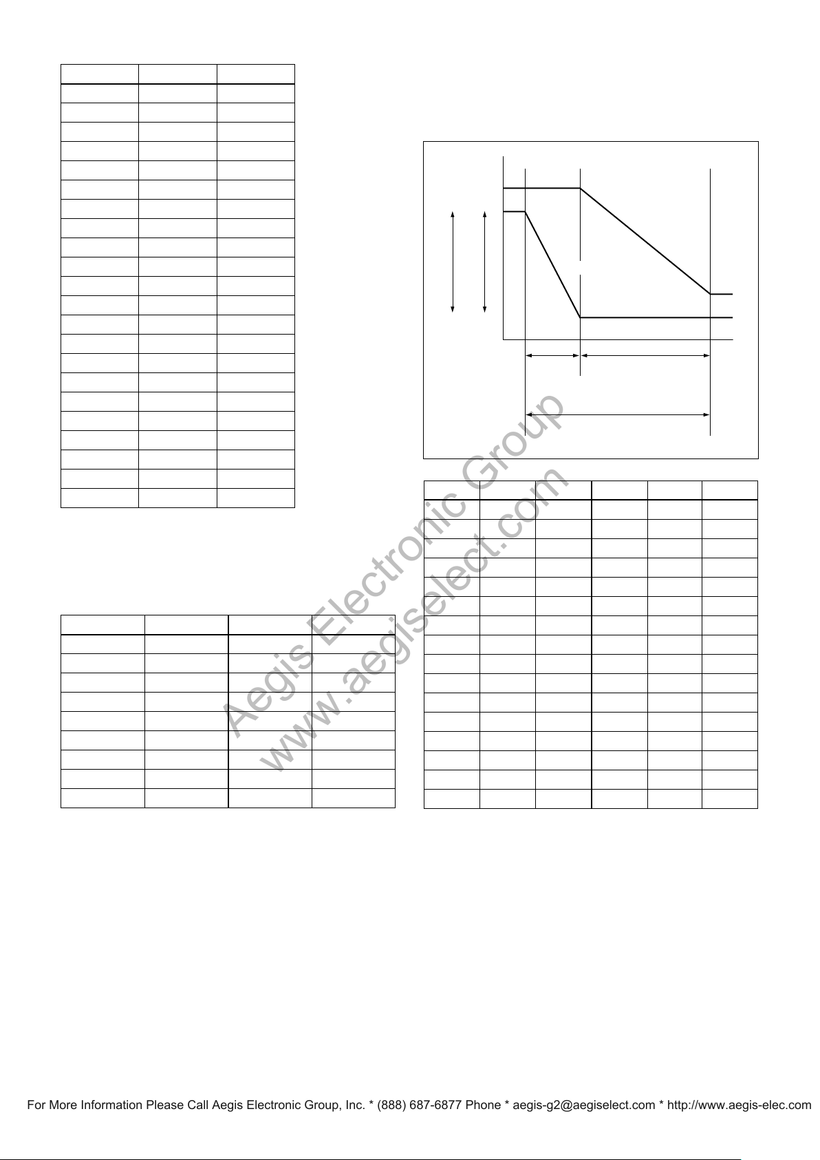
Data NTSC (s) PAL (s)
15 1/10000 1/10000
14 1/6000 1/6000
13 1/4000 1/3500
12 1/3000 1/2500
11 1/2000 1/1750
10 1/1500 1/1250
0F 1/1000 1/1000
0E 1/725 1/600
0D 1/500 1/425
0C 1/350 1/300
0B 1/250 1/215
0A 1/180 1/150
09 1/125 1/120
08 1/100 1/100
07 1/90 1/75
06 1/60 1/50
05 1/30 1/25
04 1/15 1/12
03 1/8 1/6
02 1/4 1/3
01 1/2 1/2
00 1/1 1/1
AE – Iris Priority
The iris can be set freely by the user to 18 steps
between F1.6 and Close.
The gain and shutter speed are set automatically,
according to the brightness of the subject.
Data Setting value Data Setting value
11 F1.4* 08 F6.8
10 F1.6 07 F8
0F F2 06 F9.6
0E F2.4 05 F11
0D F2.8 04 F14
0C F3.4 03 F16
0B F4 02 F19
0A F4.8 01 F22
09 F5.6 00 CLOSE
* For EVI-D80N/P this setting is F1.4, EVI-D90N/P is F1.35.
Mode, the current status will be retained for a short
period of time.
Only when the AE mode is set to “Full Auto” or
“Shutter Priority,” can you switch it to “Bright.”
Gain
IRIS gain curve
AGC gain curve
Dark Bright
Controlled
by gain
Bright limit controllable
for this unit
Data Iris Gain Data Iris Gain
1F F1.4* 28 dB 0F F2 0 dB
1E F1.4* 26 dB 0E F2.4 0 dB
1D F1.4* 24 dB 0D F2.8 0 dB
1C F1.4* 22 dB 0C F3.4 0 dB
1B F1.4* 20 dB 0B F4 0 dB
1A F1.4* 18 dB 0A F4.8 0 dB
19 F1.4* 16 dB 09 F5.6 0 dB
18 F1.4* 14 dB 08 F6.8 0 dB
17 F1.4* 12 dB 07 F8 0 dB
16 F1.4* 10 dB 06 F9.6 0 dB
15 F1.4* 8 dB 05 F11 0 dB
14 F1.4* 6 dB 04 F14 0 dB
13 F1.4* 4 dB 03 F16 0 dB
12 F1.4* 2 dB 02 F19 0 dB
11 F1.4* 0 dB 01 F22 0 dB
10 F1.6 0 dB 00 CLOSE 0 dB
* For EVI-D80N/P this setting is F1.4, EVI-D90N/P is F1.35.
Controlled by IRIS
AE – Manual
The shutter speed (22 steps), iris (18 steps) and gain
(16 steps) can be set freely by the user.
AE – Bright
The bright
control function adjusts both gain and iris
When switching from the Shutter Priority mode to the
Bright mode, the shutter speed set in the Shutter
Priority mode is maintained.
using an internal algorithm, according to a brightness
level freely set by the user. Exposure is controlled by
gain when dark, and by iris when bright.
As both gain and iris are fixed, this mode is used when
from Full Auto or Shutter Priority Mode to Bright
exposing at a fixed camera sensitivity. When switching
Page 11
Basic Functions
Aegis Electronic Group
www.aegiselect.com
For More Information Please Call Aegis Electronic Group, Inc. * (888) 687-6877 Phone * [email protected] * http://www.aegis-elec.com
Exposure Compensation
Exposure compensation is a function which offsets the
internal reference brightness level used in the AE mode
by steps of 1.5 dB.
Data Step Setting value
0E +7 +10.5 dB
0D +6 +9 dB
0C +5 +7.5 dB
0B +4 +6 dB
0A +3 +4.5 dB
09 +2 +3 dB
08 +1 +1.5 dB
07 0 0 dB
06 –1 –1.5 dB
05 –2 –3 dB
04 –3 –4.5 dB
03 –4 –6 dB
02 –5 –7.5 dB
01 -6 -9 dB
00 -7 -10.5 dB
Wide Dynamic Range Mode (WD) (EVI-D90N/P
only)
The Wide Dynamic Range mode is a function for
dividing an image into several blocks and correcting
blocked-up shadows and blown-out highlights in
accordance with the intensity difference. It enables you
to obtain images in which portions ranging from dark
to light can be recognized, even when capturing a
subject with a large intensity difference that is backlit
or includes extremely light portions.
A CCD for shooting a wide dynamic range is
employed, and a newly developed image signal
processor combines a long exposure signal (normal
shutter) and a signal of the high intensity portions
obtained by a short exposure (high-speed shutter) to
achieve images with a wide dynamic range.
Wide Dynamic Range Auto On/Off Mode
The wide dynamic range can be set to be automatically
switched ON/OFF in accordance with the intensity
difference obtained by dividing an image into several
blocks and then averaging the intensity of each block.
High Resolution Mode
A newly developed ISP function enables the filtering
of signals. This allows the camera to provide images
with a high resolution.
Aperture Control
Aperture control is a function which adjusts the
enhancement of the edges of objects in the picture.
There are 16 levels of adjustment, starting from “no
enhancement.” When shooting text, this control may
help by making the text sharper.
Back Light Compensation
When the background of the subject is too bright, or
when the subject is too dark due to shooting in the AE
mode, back light compensation will make the subject
appear clearer.
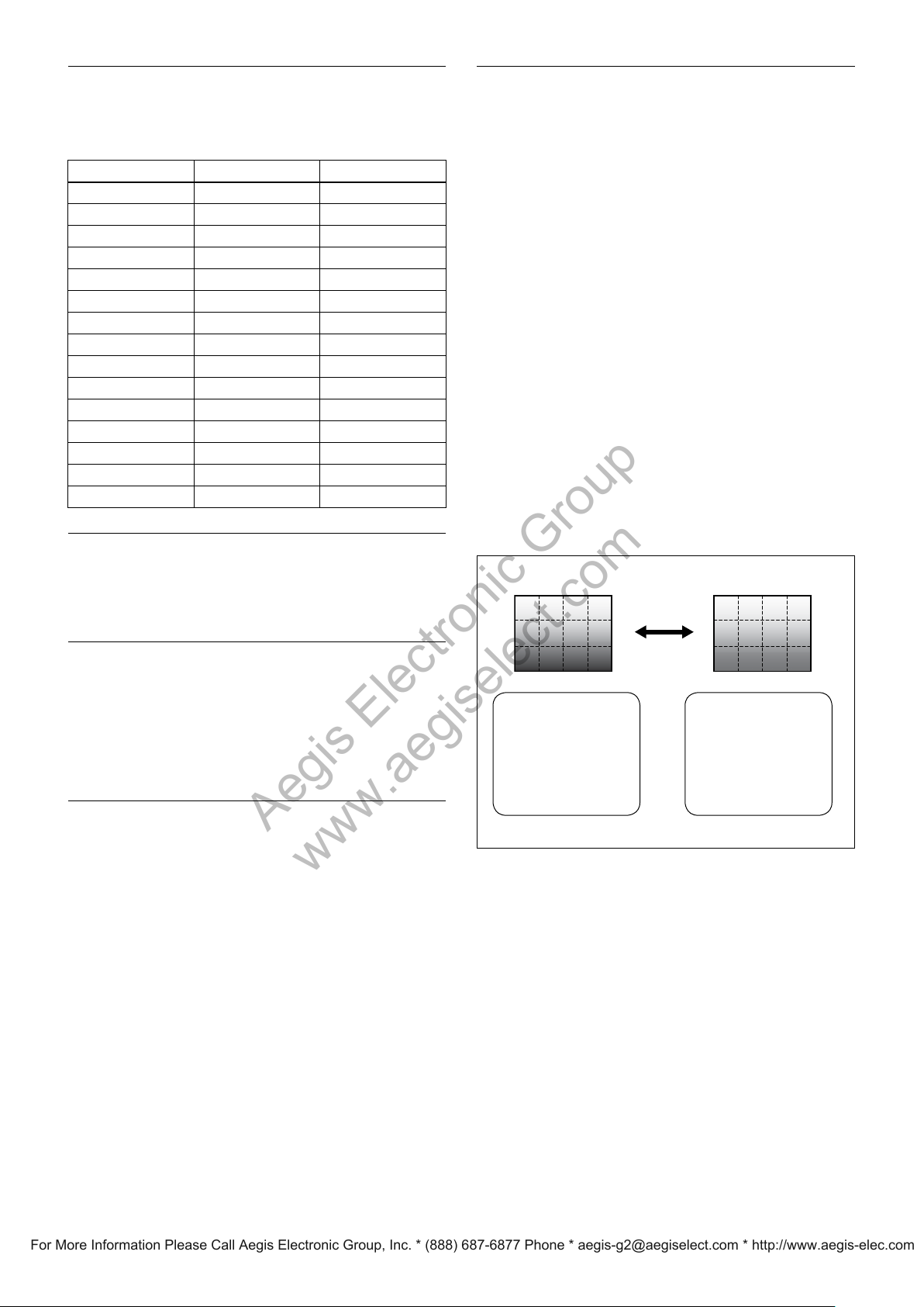
Wide Dynamic Range Auto On/Off Mode
Auto On/Off
When the intensity
difference between the
dark portions and light
portions of a subject
becomes large because
of back lighting or the
like, the wide dynamic
range mode is switched
ON.
When the subject
changes and the
intensity difference
between the dark
portions and light
portions becomes
small, the wide dynamic
range mode is switched
OFF.
11
Page 12
12
Basic Functions
Aegis Electronic Group
www.aegiselect.com
For More Information Please Call Aegis Electronic Group, Inc. * (888) 687-6877 Phone * [email protected] * http://www.aegis-elec.com
The wide dynamic range mode includes the following
operation modes.
WD Mode
This mode co
blownout highlights in accordance with the intensity
difference.
WD Auto ON/OFF Mode
This mode sw
accordance with the intensity difference of the
subject. Configure the sensitivity for when WD is
switched from OFF to ON with the detection
sensitivity parameter.
Exposure Ratio Mode
This mode fixes the shutter speed of a short
exposure. Configure the shutter speed of a long
exposure by setting the ratio with regards to a short
exposure with the exposure ratio parameter.
Blocked-up shadow correction is not performed in
this mode.
Histogram Mode
This mode u
shadows and blown-out highlights.
About WD Set Parameter
(Command: 8x 01 04 2D 0p 0q 0r 0s 0t 0u 00 00
FF)
p: Screen dis
division, 2: Long-time, 3: Short-time) Set the
screen display to a WD combination image,
long/short exposure division image, long
exposure image, or short exposure image.
q: Detection sensitivity (0: Low, 1: Mid, 2: Hi) Select
from three levels for detecting the intensity
within the image for when switching Auto WD
from OFF to ON.
r: Blocked-up shadow correction level can be
s: Blown-out highlight correction level can be
tu: Parameter to use in the exposure ratio mode.
rrects blocked-up shadows and
itches WD ON/OFF automatically in
ses a histogram to correct blocked-up
play (0: Combined image, 1: Long/short
set to one of four levels. (0:L 1:M 2:H 3:S)
set to one of three levels. (0:L 1:M 2:H)
Specify the short exposure time by setting
the magnification ratio (×1 to ×150) with
regards to a long exposure time.
Noise Reduction
The NR (Noise Reduction) function removes noise
(both random and non-random) to provide clearer
images. By combining 2D filtering according to
brightness and image color, and 3D filtering according
to noise caused by motion and time difference, lower
noise images can be obtained for the corresponding
image brightness of a moving subject.
This function has six steps: levels 1 to 5, plus off.
Level 1 applies to subject motion mainly using 2D
filter effects. With level 5, 2D and 3D filter effects are
maximized, providing the lowest-noise images,
although moving subjects may show trails.
At each level, two filters are set according to noise and
image motion characteristics, so the available level
selections depend on the situation. The default setting
is level 3.
Image Stabilizer (EVI-D90N/P only)
Switching ON the Image Stabilizer function reduces
image blurring caused by, for example, vibration,
which allows you to obtain images without much
blurring. A correction effect of approximately 90% is
possible for a vibration frequency of around 10 Hz.
The Image Stabilizer function employs the digital
zoom system, so the angle of view and resolution are
changed, but the sensitivity is maintained.
Hold Function of Image Stabilizer
With the Image Stabilizer function, suddenly stopping
high-speed movement (pan, tilt, etc.) of the camera
produces a blur sensor counteraction that may cause
image movement. In such a case, you can use a
command setting (hold) to maintain the correction of
the Image Stabilizer function. In this case the image
stabilizer is off, but there is no change in the angle of
view.
Note
When the wide dynamic range mode is ON, solarization may be observed in the images of some subjects.
This phenomenon is unique to wide dynamic range
mode, and is not an indication of a camera
malfunction.
Page 13
Basic Functions
ICR
SHUTTER
Dark Bright
AGC
MAX
IRIS
OPEN
Shutter 1/60 sec
ICR OFF U ON
GAIN
ICR ON
IRIS
Aegis Electronic Group
www.aegiselect.com
For More Information Please Call Aegis Electronic Group, Inc. * (888) 687-6877 Phone * [email protected] * http://www.aegis-elec.com
Slow shutter – Auto/Manual
When set to “Auto,” ensures that the slow shutter is set
automatically when the brightness drops. Effective
only when the AE mode is set to “Full Auto.”
Set to “Slow Shutter Manual” at shipment.
Note
The Slow Shutter Auto function is not available in WD
mode
ICR (IR Cut-Removable) Mode (EVI-D90N/P
only)
An infrared (IR) Cut-Filter can be disengaged from the
image path for increased sensitivity in low light
environments. The ICR will automatically engage
depending on the ambient light, allowing the camera to
be effective in day/night environments.
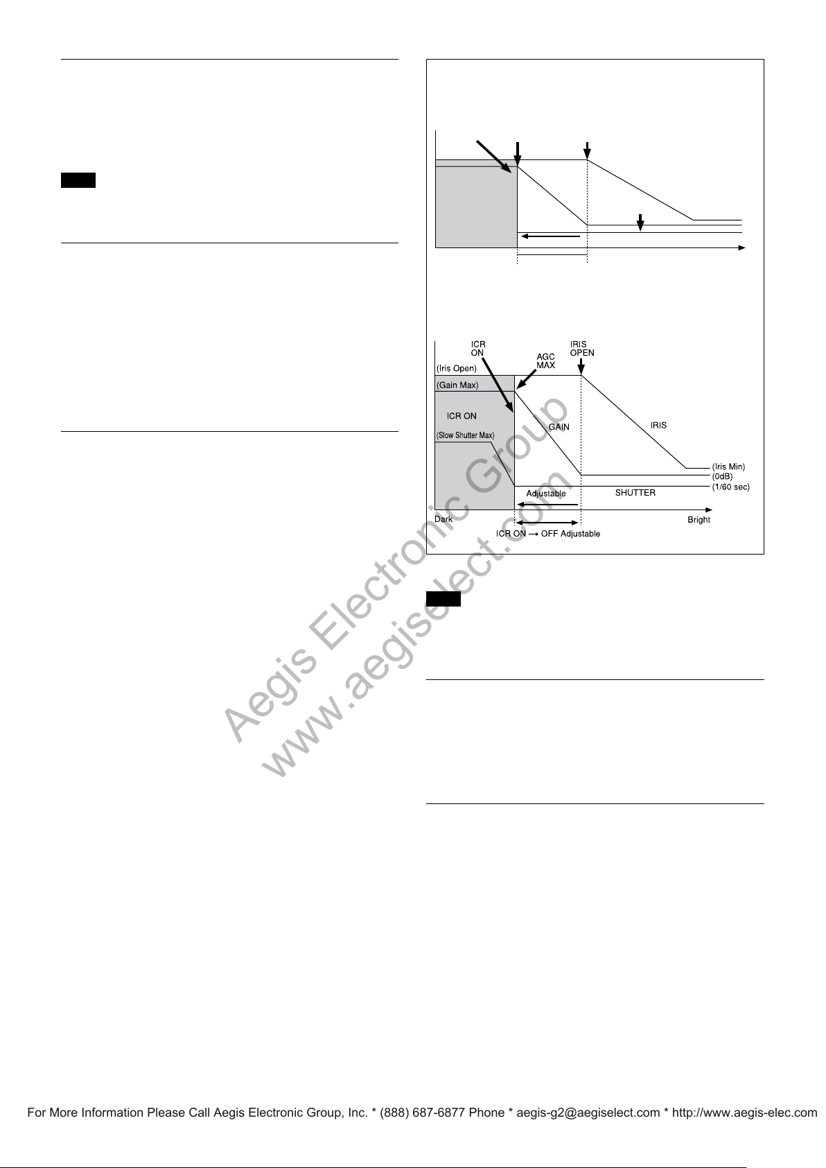
When the auto ICR mode is set to ON, the image
becomes black and white.
Auto ICR Mode (EVI-D90N/P only)
Auto ICR Mode automatically switches the settings
needed for attaching or removing the IR Cut Filter.
With a set level of darkness, the IR Cut Filter is
automatically disabled (ICR ON), and the infrared
sensitivity is increased. With a set level of brightness,
the IR Cut Filter is automatically enabled (ICR OFF).
Also, on systems equipped with an IR light, the
internal data of the camera is used to make the proper
decisions to avoid malfunctions.
Auto ICR Mode operates with the AE Full Auto
setting.
When Auto Slow Shutter is OFF (initial setting)
When Auto Slow Shutter is ON
Note
When in Auto_ICR_OFF state and WB data is added
(default), a malfunction may occur when the subjects
largely consisting of blue and green colors are taken.
Camera ID
The ID can be set up to 65,536 (0000 to FFFF). As this
will be memorized in the nonvolatile memory inside
the camera, data will be saved regardless of whether it
has been backed up.
Effect
It consists of the following functions.
• Neg. Art: Negative/Positive Reversal
me Image
• Black Whi
te: Monochro
13
Page 14

Basic Functions
Aegis Electronic Group
www.aegiselect.com
For More Information Please Call Aegis Electronic Group, Inc. * (888) 687-6877 Phone * [email protected] * http://www.aegis-elec.com
Checking the Location of the Camera for
Signals from the IR Remote Commander
The supplied Remote Commander may not work
correctly near inverter lighting fixtures. Good IR
detection can be verified to determine proper camera
location.
While the camera is being initialized after the power is
turned on by connecting the camera to an AC outlet
using the AC power adaptor and AC power cord, or by
using a VISCA command, the camera detects whether
or not the camera is able to receive infrared signals
from the Remote Commander. You can check the result
of this operation via the IR_ConditionInq command
(see page 33).
When the installation location does not allow stable
reception, try to install the camera farther away from
the inverter lighting fixtures.
Others
Power On/Off
Powers the camera on and off. When the power is off,
the camera is able to accept only the lowest level of
VISCA Commands and POWER of the Remote
Commander; the display and other features are turned
off.
I/F clear
Clears th
the buffer can also be carried out from the control
application software when the power is on.
Address set
VISCA is a p
daisy chain of up to seven attached devices. Therefore,
whenever a camera is connected for the first time, be
sure to use the address set to confirm the address.
e Command buffer of the camera. Clearing
rotocol, which normally can support a
Memory (Position Preset)
Using the position preset function, 6 sets of camera
shooting conditions can be stored and recalled.
This function allows you to achieve the desired status
instantly without adjusting the following items each
time.
Pan/Tilt Posi
Zoom Positi
Digital Zoom On/Off
ocus Auto/Ma
F
Focus Positi
AE Mode
er co
Shutt
Bright Contr
Iris control p
Gain contro
Exposure Comp
Exposure Leve
Backlight Compe
Slow Shutt
White Balance M
R/B Gain
Aperture
ICR S
WD On/Of
The set
For setting items, see the “Initial Settings, Position Preset”
section on page 15.
Note
If the camera is placed on a desk, when you pan the
camera to the right or left beyond 120° with the camera
tilted downward by 20° (or tilted upward by 20° if it is
installed on a ceiling), the camera base may be
captured by the lens, depending on the zoom position
of the lens.
hoot On/Off (EVI-D90N/P only)
tings are recalled when the power is turned on.
tion
on
nual
on
ntrol parameters
ol
arameters
l parameters
ensation On/Off
l
nsation On/Off
er Auto/Manual
ode
f (EVI-D90N/P only)
14
Page 15

Initial Settings and Position Preset
Aegis Electronic Group
www.aegiselect.com
For More Information Please Call Aegis Electronic Group, Inc. * (888) 687-6877 Phone * [email protected] * http://www.aegis-elec.com
Basic Functions
The initial values are those set at the factory. Settings
for items in Position presets 1 to 6 that will be retained
even when the power to the camera is turned off are
indicated by a “Yes,” those that will be lost are indicated
by an “No.”
When the power is turned on, the settings retained in
POSITION 1 will be called up as the initial settings.
When a CAM_M
Mode/Position Initial settings
Pan/Tilt Position Home position
Pan/Tilt Limit Position movable-range maximum
Zoom Position Wide end
D-Zoom On/Off on
Focus Position —
Focus Auto/Manual Auto
Near Limit Setting 9000h (30 cm)
AF Sensitivity Normal
AF Mode Normal
AF Run Time 5 sec
AF Interval 5 sec
WB Mode Auto
WB Data (Rgain, Bgain) —
One Push WB Data —
AE Mode Full Auto
WD On/Off/Auto Off
Slow Shutter Mode Manual
Shutter Position 1/60sec (NTSC), 1/50sec (PAL)
Iris Position —
Gain Position —
Bright Position —
Exposure Compensation On/Off Off
Exposure Compensation Amount ±0
BackLight On/Off Off
Aperture Level 6
High Resolution Mode On/Off Off
Picture Effect Off
ICR On/Off
Auto ICR On/Off
Auto ICR Threshold Level
Image Stabilizer On/Off/Hold
NR Level 3
AE Gain Limit —
Camera ID 0000h
IR_Receive On/Off On
IR_ReceiveReturn On/Off Off
Display Information On
1)
The settin
Notes
The number of times data can be written to the EEPROM (by executing Position Preset) is limited.
If you want the camera status and Pan/Tilt positions in effect before the camera is turned off to be retained when the power
1)
g is available on EVI-D90N/P only.
emory Reset command is sent, or a
1)
1)
1)
Off
Off
0Ah
Off
choice is made from POSITION 1 to 6 while the
RESET button on the Remote Commander is being
pressed, the settings selected will be used as the
initial settings.
Position p
reset 1 becomes VISCA command CAM_
Memory memory number 0. Position presets 2
through 6 become VISCA command CAM_Memory
memory numbers 1 through 5.
Position
preset 1
a a
a a
a a
a a
a a
a a
a a
a a
a a
a a
a a
a a
a a
a a
a a
a a
a a
a a
a a
a a
a a
a a
a a
a a
a a
a a
a a
a a
a a
a a
a a
a a
a
a
a
Position
presets 2 to 6
is turned OFF, then turned ON again, have the camera memorize those positions in POSITION 1.
It takes approximately 2 seconds longer to memorize or erase settings in POSITION 1 than it does to memorize or erase
settings in any other channel.
Camera ID data will be saved regardless of the position preset.
If IMAGE FLIP or D70 mode has been switched, all of the Position Presets are reset to their initial values.
15
Page 16
Basic Functions
Aegis Electronic Group
www.aegiselect.com
For More Information Please Call Aegis Electronic Group, Inc. * (888) 687-6877 Phone * [email protected] * http://www.aegis-elec.com
Command
Memory
During displaying the menu
3)
Initializing
2)
IFC
No
No
6)
4) 6)
o Yes No
o No Yes No
5)
No
No
6)
Yes Yes
6)
1)
o No No Yes
Power Off
Mode Power On
at the Home position, until the video signal is output. Or the period from the time the CAM Power ON command is sent, until Completion is returned.
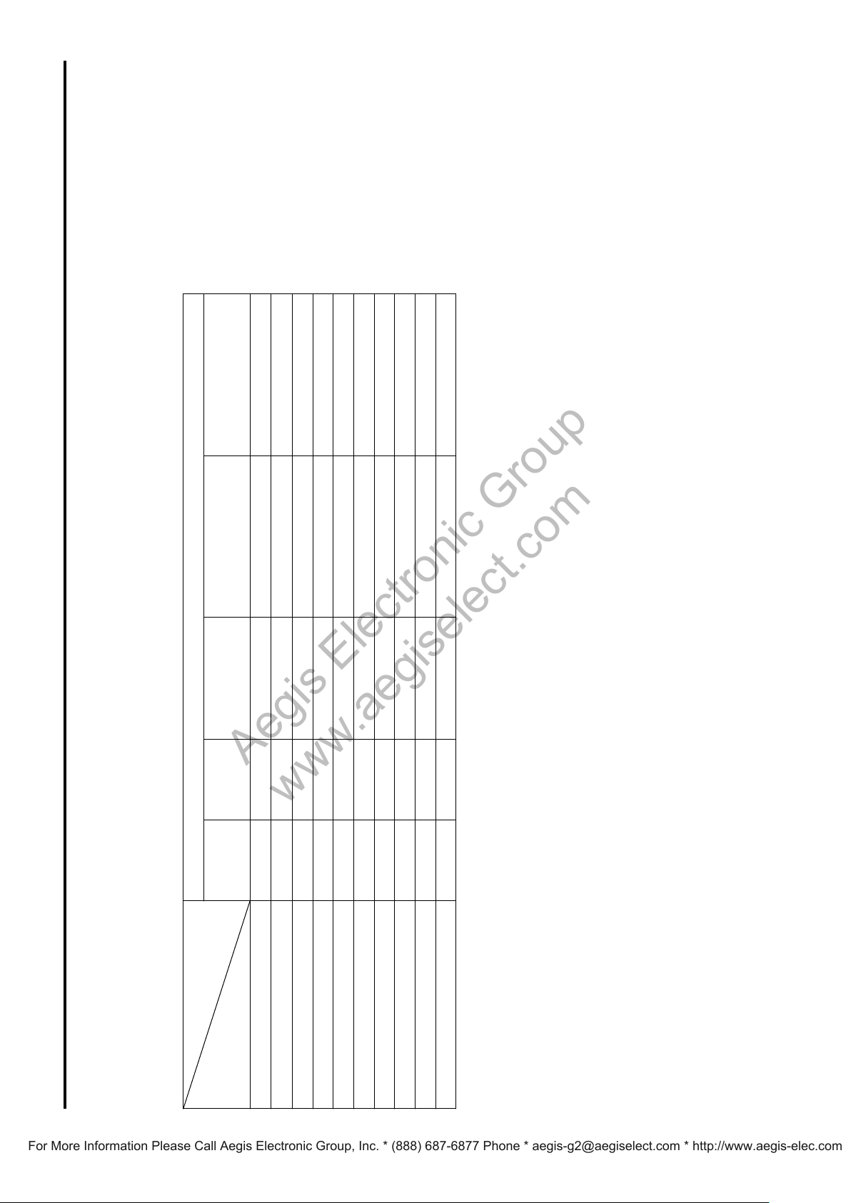
Mode Condition
Basic settings
Command
Address Set Yes Yes Yes Yes Yes
IF_Clear Yes Yes Yes Yes Yes
CAM_Power On Yes No N
CAM_Power Off Yes N
IR_Receive On/Off N
IR_ReceiveReturn On/Off No No No Yes
CAM_Versionq Yes Yes Yes
InquiryCommand (and similar commands) No No No Yes
CAM_PowerInq Yes Yes Yes Yes Yes
BlockInquiry No No No Yes
and stops
1) DC power is being supplied, but the camera has been turned off by a VISCA command.
2) The period from the time IF Clear is sent, until the Reply Packet is returned.
3) The period from the time DC power is turned on or the camera is turned on via a VISCA command, and the camera subsequently finishes the pan/tilt reset operation
4) The camera does not receive the operation sent from the Remote Commander.
5) Commands can be executed after the pan/tilt movement has been started. Before that, camera movement may be inconsistent.
6) When the menu display is updating, operation is not possible.
16
Page 17
Basic Functions
Aegis Electronic Group
www.aegiselect.com
For More Information Please Call Aegis Electronic Group, Inc. * (888) 687-6877 Phone * [email protected] * http://www.aegis-elec.com
Power On
Memory Recall
the menu
During displaying
No
No
No
No
No
No
No
No
No
No
No
No
No
No
No
No
No
Memory Recall
4)
4)
4)
4)
4)
4)
4)
4)
4)
4)
4)
4)
4)
4)
4)
4)
4)
the menu
During displaying
No Yes
5)
Power On
1)
Power Off
Mode
Zoom Direct Focus Direct AF ON
3)
Initializing
2)
IFC
Mode
White balance mode
3)
Initializing
2)
IFC
1)
Power Off
No No No Yes Yes Yes Yes Yes Yes
No No No No No No No Yes Yes
the period from the time the CAM Power ON command is sent, until Completion is returned.
the period from the time the CAM Power ON command is sent, until Completion is returned.
oom Tele/Wide/Stop [VISCA] No No No No Yes Yes Yes
Zoom/Focus
Command
CAM_Z
CAM_Zoom Tele/Wide/Stop [RC] No No No No Yes Yes Yes
CAM_Zoom Direct No No No Yes Yes Yes Yes
D-Zoom Limit No No No No Yes Yes Yes
CAM_Focus Far/Near/Stop [VISCA] No No No Yes No No Yes
CAM_Focus Far/Near/Stop [RC] No No No Yes No No Yes
CAM_Focus Direct No No No Yes Yes No Yes
CAM_Focus Mode (Auto/Manual) No No No Yes No Yes Yes
CAM_Focus One Push Trigger No No No Yes No No Yes
CAM_Focus Infinity No No No Yes No Yes Yes
CAM_Focus Near Limit No No No Yes No Yes Yes
AF Sensitivity Normal/Low No No No Yes Yes Yes Yes
AF Mode Norm/Interval/Zoom No No No Yes Yes Yes Yes
AF Activation Time/Interval Setting No No No Yes Yes Yes Yes
output. Or
4) When the menu display is updating, operation is not possible.
1) DC power is being supplied, but the camera has been turned off by a VISCA command.
2) The period from the time IF Clear is sent, until the Reply Packet is returned.
3) The period from the time DC power is turned on or the camera is turned on via a VISCA command, and the camera subsequently finishes the pan/tilt reset operation and stops at the Home position, until the video signal is
White Balance
Command Auto Indoor Outdoor One Push Manual
CAM_WB Auto/Indoor/Outdoor/
OnePhshWB/Manual
CAM_WB One Push Trigger No No No No No No Yes
CAM_WB R(B) Gain
Reset/Up/Down/Direct
output. Or
4) When the menu display is updating, operation is not possible.
1) DC power is being supplied, but the camera has been turned off by a VISCA command.
2) The period from the time IF Clear is sent, until the Reply Packet is returned.
5) Commands are ignored during a One Push AWB operation.
3) The period from the time DC power is turned on or the camera is turned on via a VISCA command, and the camera subsequently finishes the pan/tilt reset operation and stops at the Home position, until the video signal is
17
Page 18
Memory
Aegis Electronic Group
www.aegiselect.com
For More Information Please Call Aegis Electronic Group, Inc. * (888) 687-6877 Phone * [email protected] * http://www.aegis-elec.com
During
displaying
Recall
the menu
Basic Functions
No
No
No
No
No
No
No
No
No
No
No
5)
5)
5)
5)
5)
5)
5)
5)
5)
5)
5)
Yes
Yes
Yes
Yes
Wide-D
8)
7)
ON
7)
7)
7)
Power Off
Exposure mode
Yes Yes Yes Yes Yes Yes
4)
Exposure
Mode
3)
Initializing
2)
IFC
1)
Power Off
Command Full Auto Bright Shutter Pri Iris Pri SPOT Light Manual
No No No Yes Yes
o/Manual/Shutter Pri/
CAM_AE
Full Aut
Iris Pri/Spot Light
No No No Yes Yes Yes Yes Yes Yes Yes Yes
No No No Yes Yes Yes Yes Yes Yes No
6)
7)
CAM_WD On/Off
CAM_Backlight On/Off No No No Yes No No No Yes No No
CAM_ExComp Reset/Up/Down/Direct
CAM_ExComp On/Off No No No Yes Yes Yes Yes Yes Yes No
CAM_Bright Up/Down/Direct No No No No Yes No No No No Yes Yes
CAM_Gain Reset/Up/Down/Direct No No No No No No No No Yes Yes Yes
CAM_Iris Reset/Up/Down/Direct No No No No No No Yes No Yes Yes Yes
CAM_Shutter Reset/Up/Down/Direct No No No No No Yes No No Yes Yes Yes
CAM_Slow Shutter Limit ON/OFF No No No Yes Yes Yes Yes Yes Yes No
CAM_AE Bright No No No Yes Yes Yes No No No Yes Yes
output. Or the period from the time the CAM Power ON command is sent, until Completion is returned.
1) DC power is being supplied, but the camera has been turned off by a VISCA command.
2) The period from the time IF Clear is sent, until the Reply Packet is returned.
3) The period from the time DC power is turned on or the camera is turned on via a VISCA command, and the camera subsequently finishes the pan/tilt reset operation and stops at the Home position, until the video signal is
4) Yes: Only when the camera changes to BRIGHT mode from Full Auto or SHUTTER Pri mode.
5) When the menu display is updating, operation is not possible.
6) No: This is not allowed when EX-COMP is set to OFF.
7) The settings are available; however, command actions will be executed only after Wide-D is set to OFF.
8) This command is available on EVI-D90N/P only.
18
Page 19
Basic Functions
Aegis Electronic Group
www.aegiselect.com
For More Information Please Call Aegis Electronic Group, Inc. * (888) 687-6877 Phone * [email protected] * http://www.aegis-elec.com
Power On
1)
No
Memory Recall
4)
the menu
During displaying
3)
Initializing
2)
IFC
No
No
No
No
No
No
4)
4)
4)
4)
4)
4)
Power Off
Mode
eset/Up/Down/Direct No No No Yes
R
e
ur
t
er
p
Command
CAM_A
Display info. (ON/OFF) No No No Yes
CAM_PictureEffect OFF/Neg.Art/B&W No No No Yes
CAM_ICR ON/OFF No No No Yes
CAM_AutoICR ON/OFF/Threshold No No No Yes
CAM_HR ON/OFF No No No Yes
Effect
CAM_NR No No No Yes
il the video signal is output. Or the period from the time the CAM Power ON command is sent, until Completion is returned.
position, unt
1) DC power is being supplied, but the camera has been turned off by a VISCA command.
2) The period from the time IF Clear is sent, until the Reply Packet is returned.
3) The period from the time DC power is turned on or the camera is turned on via a VISCA command, and the camera subsequently finishes the pan/tilt reset operation and stops at the Home
4) When the menu display is updating, operation is not possible.
19
Page 20
Position
Aegis Electronic Group
www.aegiselect.com
For More Information Please Call Aegis Electronic Group, Inc. * (888) 687-6877 Phone * [email protected] * http://www.aegis-elec.com
detection error
During
displaying the
menu
Basic Functions
8)
8)
No
Yes
5)
5)
No
Yes
5)
5)
No
Yes
5)
5)
Yes
5)
Reset execution Memory Recall
Home
Pan/Tilt normal status
Power On
Relative
Position
Position
Absolute
Pan/tilt
movement
Focus
(Direct)
Zoom
(Direct)
execution
execution
execution
4)
according to
the command
3)
7)
6)
Common Common VISCA RC VISCA VISCA VISCA RC VISCA RC VISCA RC
Yes Yes No No Yes
10)
No
10)
No
10)
No
10)
No
10)
No
10)
No No No No No No No No Yes Yes No No
No No No No No No No No Yes Yes No No
7)
No
No
6)
Initia-
lizing
2)
IFC
1)
Off
Power
Mode
Pan/Tilt
ice
dev
ransmit
T
Command
RC No No No Yes Yes No No No No No Yes No No No No No No
RC No No No Yes Yes Yes No No No No No No No No No No Yes
VISCA No No No Yes Yes Yes Yes No No No No No No No No No Yes
e Up/Down/Left/
Right/UpLeft/UpRight/
DownLeft/DownRight
Pan-tiltDriv
Pan-tiltDrive Stop VISCA No No No Yes Yes Yes Yes No No No No No No No No No Yes
VISCA No No No Yes Yes No No No No Yes No No No No No No No
Pan-tiltDrive RelativePosition VISCA No No No Yes Yes No No No No No No No No No No Yes
Pan-tiltDrive AbsolutePosition VISCA No No No Yes Yes No No Yes No No No No No No No Yes
Pan-tiltDrive Home
RC No No No Yes Yes No No No No No No No No No No Yes
VISCA No No No Yes Yes No No No No No No No No No No Yes
tDrive Reset
Pan-til
Pan-tiltLimitSet LimitSet VISCA No No No Yes Yes Yes Yes No No No No No No No No Yes
Pan-tiltLimitSet LimitClear VISCA No No No Yes Yes Yes Yes No No No No No No No No Yes
Memory Set Common No No No No No No No No No No No No No No No No No
RC No No No No
VISCA No No No No
VISCA No No No Yes Yes No
t operation works by Pan-tiltDrive Up/Down/Left/Right/UpLeft/UpRight/DownLeft/DownRight commands.
l
Reset Common No No No No No No No No No No No No No No No No No
Memory
9)
Recall
CAM_NR
Memory
1) DC power is being supplied, but the camera has been turned off by a VISCA command.
i
n/t
a
p
e
output.
2) The period from the time IF Clear is sent, until the Reply Packet is returned.
3) The period from the time DC power is turned on or the camera is turned on via a VISCA command, and the camera subsequently finishes the pan/tilt reset operation and stops at the Home position, until the video signal is
4) Th
5) When the menu display is updating, operation is not possible.
6) Yes: while the camera operates in Tele/Wide zoom mode.
please transmit the command again.
7) Yes: while the camera operates in Far/Near focus mode.
8) Yes: only for movements away from the direction where a position detection error has been recognized.
9) When CAM commands or other inquiry commands are received after the pan/tilt movement has been stopped, “Command not executable” may be returned for a maximum of 120 msec due to internal processing. In this case,
10) Yes: when pan/tilt moves at high speed.
20
Page 21
Command List
VISCA Equipment
IN
OUT
IN
OUT
IN
OUT
VISCA Controller
Aegis Electronic Group
www.aegiselect.com
For More Information Please Call Aegis Electronic Group, Inc. * (888) 687-6877 Phone * [email protected] * http://www.aegis-elec.com
VISCA1) RS-232C Commands
Use of RS-232C control software which has been
developed based upon this command list may cause
malfunction or damage to hardware and software. Sony
Corporation is not liable for any such damage.
Overview of VISCA
In VISCA, the device producing the commands, for
example, a computer, is called the controller, while the
device receiving the commands, such as an
EVI-D80N/D80P/D90N/D90P, is c
device. The EVI-D80N/D80P/D90N/D90P serves as a
peripheral device in VISCA. In VISCA, up to seven
peripheral devices like the EVI-D80N/D80P/D90N/
D90P can be connected to one controller using
communication conforming to the RS-232C standard.
The parameters of RS-232C are as follows.
Communicatio
Data bi
Start b
Stop bi
Non par
Flow control using XON/XOFF and RTS/CTS, etc., is
not supported.
ts : 8
it : 1
t : 1
ity
alled the peripheral
n speed: 9,600 bps/38,400 bps
The VISCA devices
OUT connector.
Set the DSR input (the DTR output of the controller) of
VISCA IN to H when controlling VISCA equipment
from the controller.
each have a VISCA IN and VISCA
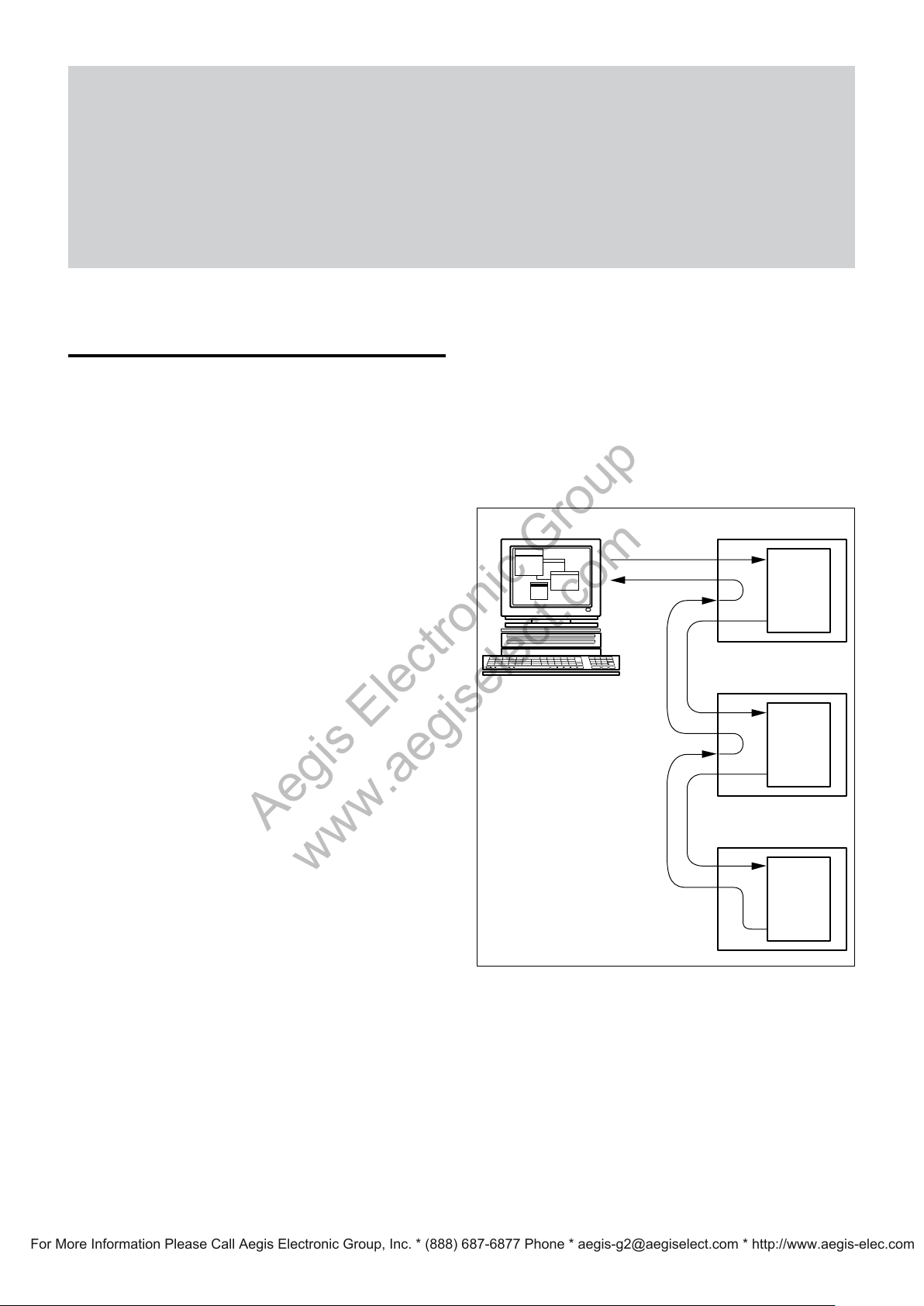
Fig. 1 VISCA network configuration
Peripheral devices are connected in a daisy chain. As
shown in Fig. 1, the actual internal connection is a onedirection ring, so that messages return to the controller
via the peripheral devices. The devices on the network
are assigned addresses.
The address of the controller is fixed at 0. The
addresses of the peripheral devices are 1, 2, 3 ... in
order, starting from the one nearest the controller. The
address of the peripheral device is set by sending
address commands during the initialization of the
network.
.......................................................................................................................................................................................................................................................
1) VISCA is a protocol which controls consumer camcorders developed by Sony. “VISCA” is a trademark of Sony Corporation.
21
Page 22
Command List
Bit 7
(MSB)
Bit 6 Bit 5 Bit 4 Bit 3 Bit 2 Bit 1 Bit 0
(LSB)
1 0
FF
Bit 7
(MSB)
Bit 6 Bit 5 Bit 4 Bit 3 Bit 2 Bit 1 Bit 0
(LSB)
1 1 1 1 1 1 1 1
Bit 0 Bit 1 Bit 2 Bit 3 Bit 4 Bit 5
(LSB) (MSB)
Bit 6 Bit 7
Aegis Electronic Group
www.aegiselect.com
For More Information Please Call Aegis Electronic Group, Inc. * (888) 687-6877 Phone * [email protected] * http://www.aegis-elec.com
VISCA Communication
Specifications
VISCA packet structure
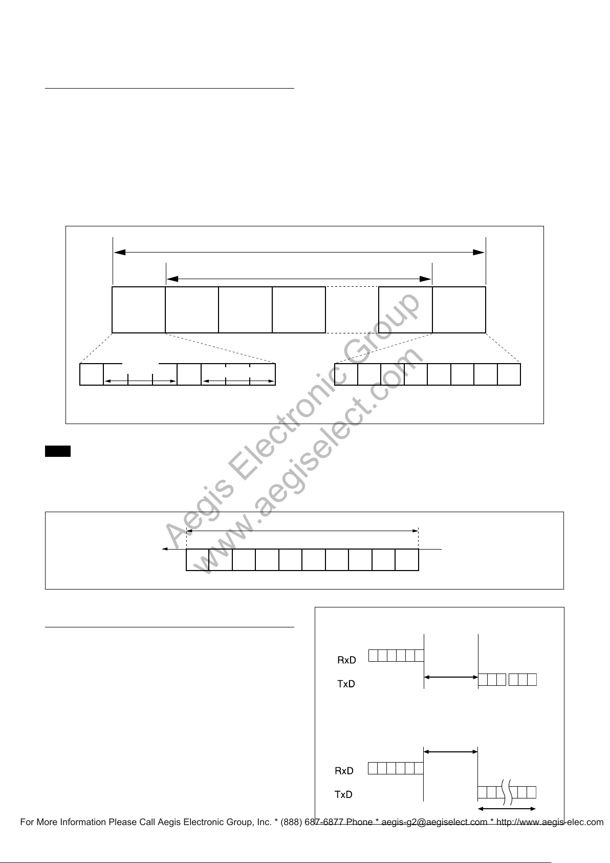
The basic unit of VISCA communication is called a
packet (Fig. 2). The first byte of the packet is called the
header and comprises the sender’s and receiver’s
addresses. For example, the header of the packet sent to
the EVI-D80N/D80P/D90N/D90P assigned address 1
from the controller (address 0) is hexadecimal 81H.
packet.
Packet (3 to 16 bytes)
Message (1 to 14 bytes)Header
Byte 1 Byte 2 Byte 3
The packet sent to the EVI-D80N/D80P/D90N/D90P
assigned address 2 is 82H. In the command list, as the
header is 8X, input the address of the EVI-D80N/
D80P/D90N/D90P at X. The header of the reply packet
from the EVI-D80N/D80P/D90N/D90P assigned
address 1 is 90H. The packet from the EVI-D80N/
D80P/D90N/D90P assigned address 2 is A0H.
Some of the commands for setting EVI-D80N/D80P/
D90N/D90P units can be sent to all devices at one time
(broadcast). In the case of broadcast, the header should
be hexadecimal 88H.
When the terminator is FFH, it signifies the end of the
Terminator
Sender’s
address
Note
Receiver’s address
Fig. 2 Packet structure
Fig. 2 shows the packet structure, while Fig. 3 shows
the actual waveform. Data flow will take place with the
LSB first.
Start
bit
Fig. 3 Actual waveform for 1 byte.
Timing Chart
As VISCA Command processing can only be carried
out one time in a Vertical cycle, it takes the maximum
1V cycle time for an ACK/Completion to be returned.
If the Command ACK/Completion communication
time can be cut shorter than the 1V cycle time, then
every 1V cycle can receive a Command.
1 byte
Stop
bit.
General Commands
Command
Query Commands
Command
ACK Completion
Within 16.7msec
(20msec PAL)
Within 16.7msec
(20msec PAL)
Completion
16 Byte
22
Page 23

Command List
Aegis Electronic Group
www.aegiselect.com
For More Information Please Call Aegis Electronic Group, Inc. * (888) 687-6877 Phone * [email protected] * http://www.aegis-elec.com
Command and inquiry
Command
Sends operational commands to the
EVI-D80N/D80P/D90N/D90P.
Inquiry
Used f
or inquiring about the current state of the
EVI-D80N/D80P/D90N/D90P.
Command Packet Note
Inquiry 8X QQ RR ... FF QQ
RR
1)
QQ = 01 (Command), 09 (Inquiry)
2)
RR = 00 (Interface), 04 (camera 1), 06 (Pan/Tilter)
X = 1 to 7: EVI-D80N/D80P/D90N/D90P address
1)
= Command/Inquiry,
2)
= category code
Responses for commands and inquiries
ACK message
Returned by the EVI-D80N/D80P/D90N/D90P
when it receives a command. No ACK message is
returned for inquiries.
Completion message
Returned
when execution of commands or inquiries is
completed. In the case of inquiry commands, it will
contain reply data for the inquiry after the 3rd byte
of the packet. If the ACK message is omitted, the
socket number will contain a 0.
Reply Packet Note
Ack X0 4Y FF Y = socket number
Completion (commands) X0 5Y FF Y = socket number
Completion (Inquiries) X0 5Y ... FF Y = socket number
X = 9 to F: EVI-D80N/D80P/D90N/D90P address + 8
Error message
When a command or inquiry command could not
be executed or failed, an error message is returned
instead of the completion message.
by the EVI-D80N/D80P/D90N/D90P
Socket number
When command messages are sent to the
EVI-D80N/D80P/D90N/D90P, it is normal to send the
next command message after waiting for the
completion message or error message to return.
However to deal with advanced uses, the EVI-D80N/
D80P/D90N/D90P has two buffers (memories) for
commands, so that up to two commands including the
commands currently being executed can be received.
When the
EVI-D80N/D80P/D90N/D90P receives
commands, it
notifies the sender which command buffer was used
using the socket number of the ACK message.
As the completion message or error message also has a
socket number, it indicates which command has ended.
Even when two command buffers are being used at any
one time, an EVI-D80N/D80P/D90N/D90P
management command and some inquiry messages
can be executed.
The ACK message is not returned for these commands
and inquiries, and only the completion message of
socket number 0 is returned.
The following command use two sockets during
execution of each command that is sent. The
EVI-D80N/D80P/D90N/D90P cannot
receive other
requests during execution of these commands. In
addition, these commands cannot be executed during
operation of other commands.
SYS_Menu
Command execution cancel
To cancel a command which has already been sent,
send the Cancel command as the next command. To
cancel one of any two commands which have been
sent, use the cancel message.
Cancel Packet Note
Cancel 8X 2Y FF Y = socket number
X = 1 to 7: EVI-D80N/D80P/D90N/D90P address, Y = socket number
The Command canceled error message will be returned
for this command, but this is not a fault. It indicates
that the command has been canceled.
Error Packet Description
X0 6Y 02 FF Syntax Error
X0 6Y 03 FF Command buffer full
X0 6Y 04 FF Command canceled
X0 6Y 05 FF No socket (to be canceled)
X0 6Y 41 FF Command not executable
X = 9 to F: EVI-D80N/D80P/D90N/D90P address + 8, Y = socket number
23
Page 24

VISCA Device Setting Command
Aegis Electronic Group
www.aegiselect.com
For More Information Please Call Aegis Electronic Group, Inc. * (888) 687-6877 Phone * [email protected] * http://www.aegis-elec.com
Before starting control of the EVI-D80N/D80P/D90N/
D90P, be sure to send the Address command and the
IF_Clear command using the broadcast function.
For VISCA network administration
Address Set
Sets an address of a peripheral device. Use when
initializing the network, and receiving the following
network change message.
Command Reply
Address Set 88 30 01 FF 88 30 0w FF
w = 2 to 7: EVI-D80N/D80P/D90N/D90P address + 8
Network Change
Sent from the peripheral device to the controller
when a device is removed from or added to the
network. The address must be re-set when this
message is received.
Command List
Received Packet
Network Change X0 38 FF
X = 9 to F: EVI-D80N/D80P/D90N/D90P address + 8
VISCA interface command
IF_Clear
Clears the command buffers in the
EVI-D80N/D80P/D90N/D90P and c
command currently being executed.
Command Packet Reply Packet Note
IF_Clear 8X 01 00 01FF Y0 50 FF
IF_Clear (broadcast) 88 01 00 01 FF 88 01 00 01 FF
X = 1 to 7: EVI-D80N/D80P/D90N/D90P address
Y = 9 to F: EVI-D80N/D80P/D90N/D90P address +8
ancels the
VISCA interface and inquiry
CAM_VersionInq
Returns information on the VISCA interface.
Inquiry Inquiry Packet Reply Packet Description
CAM_VersionInq 8X 09 00 02 FF Y0 50 GG GG HH HH JJ JJ KK FF GGGG = Vender ID
(0001: Sony)
HHHH = Model ID
050C: EVI-D80N/P
050D: EVI-D90N/P
JJJJ = ROM revision
X = 1 to 7: EVI-D80N/D80P/D90N/D90P address (For inquiry packet)
X = 9 to F: EVI-D80N/D80P/D90N/D90P address +8 (For reply packet)
KK = Maximum socket # (02)
24
Page 25
Command List
Aegis Electronic Group
www.aegiselect.com
For More Information Please Call Aegis Electronic Group, Inc. * (888) 687-6877 Phone * [email protected] * http://www.aegis-elec.com
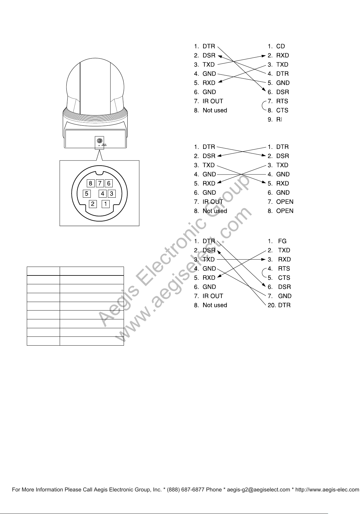
Pin assignment
VISCA IN connector (mini-DIN 8-pin, female)
EVI-D80N/D80P/ Windows
D-sub 9 pin
D90N/D90P
EVI-D80N/D80P/ EVI Camera or Mini
D90N/D90P DIN 8 pin
serial
VISCA IN
No Pins
1 DTR IN*
2 DSR IN*
3 TXD
4
5 RXD IN
6 GND
7
8 N
* The “IN” in the function names for pins 1 and 2 (“DTR IN” and
“DSR IN”) are in reference to being within the VISCA IN
connector. For details on signal direction, see the diagrams to the
right.
** You can
change ON/OFF of IR OUT of pins 7 using the
BOTTOM switch (see page 6).
IN
GND
IR OUT**
used
ot
EVI-D80N/D80P/ Windows D-sub 25 pin
D90N/D90P
25
Page 26
Command List
1 2 3 4 5
VISCA RS-422
6 7 8 9
1 2 3 4 5 6 7 8 9
Aegis Electronic Group
www.aegiselect.com
For More Information Please Call Aegis Electronic Group, Inc. * (888) 687-6877 Phone * [email protected] * http://www.aegis-elec.com
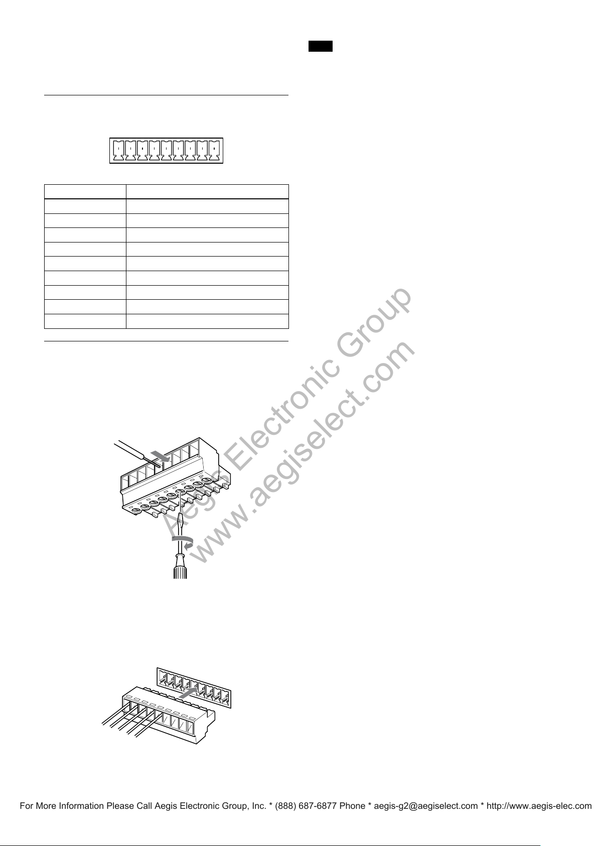
Using the VISCA RS-422 connector
pin assignments
The VISCA RS-422 connector pin assignments
Pin No. Function
1 TXD IN+
2 TXD IN–
XD O
IN+
IN–
OUT+
UT–
OUT+
UT–
3 RXD
4 RXD
5 GND
6 TXD
7 T
8 RXD
9 RXD O
Note
In order to stabilize the voltage level of the signal, connect both
ends to GND.
Do not
make a VISCA RS-232C connection when there is
already an existing VISCA RS-422 connection.
Using the VISCA RS-422 connector plug
1
Insert a wire (AW G Nos. 28 to 18) into the desired
wire opening on the supplied VISCA RS-422
connector plug, and tighten the screw for that wire
using a flat-head screwdriver.
Wire
Flat-head screwdriver
2
Insert the VISCA RS-422 connector plug into the
VISCA RS-422 connector on the rear of the
camera.
26
Page 27
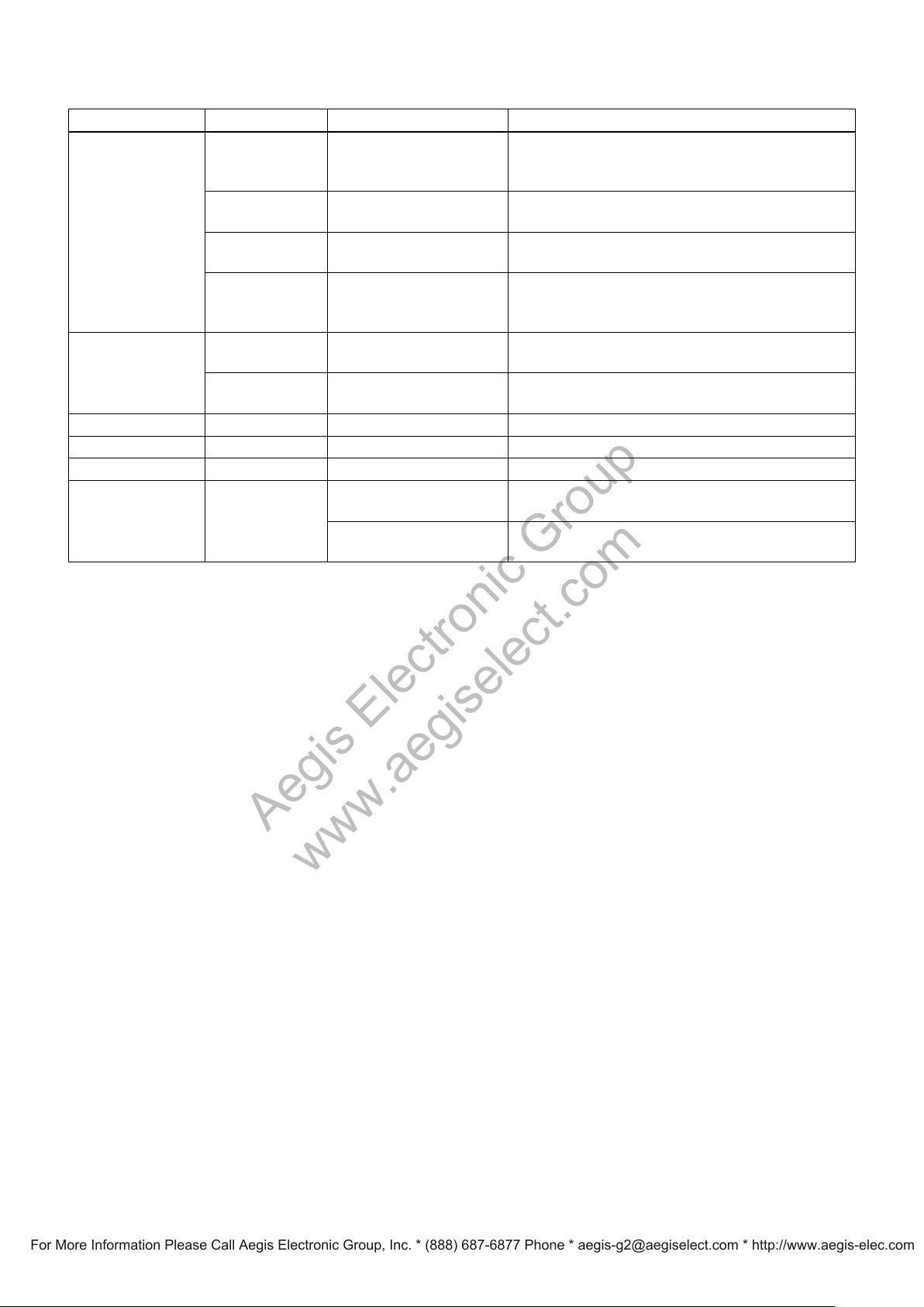
VISCA Command/ACK Protocol
Aegis Electronic Group
www.aegiselect.com
For More Information Please Call Aegis Electronic Group, Inc. * (888) 687-6877 Phone * [email protected] * http://www.aegis-elec.com
Command Command Message Reply Message Comments
General Command 81 01 04 38 02 FF
(Example)
81 01 04 38 FF
(Example)
81 01 04 38 02 FF
(Example)
81 01 04 08 02 FF
(Example)
Inquiry Command 81 09 04 38 FF
(Example)
81 09 05 38 FF
(Example)
Address Set 88 30 01 FF 88 30 0w FF w: Returned the device address to +1. (2 to 8)
IF_Clear(Broadcast) 88 01 00 01
IF_Clear (For x) 8x 01 00 01 FF z0 50 FF (Completion) ACK is not returned for this command.
Command Cancel 8x 2y FF
(y:Socket N
FF 88 01 00 01 FF Returned the same command.
o.)
90 41 FF (ACK)+90
(Completion)
90 42 FF 90 52 FF
90 60 02 FF
90 60 03 FF
mmand Buffer Full)
(Co
90 61 41 FF
mmand Not Executable)
(Co
90 62 41FF
90 50 02 FF
90 60 02 FF
z0 6y 04 FF
(Command Canceled)
z0 6y 05 FF (No Socket) Returned when the command of the specified socket has already
51 FF
(Syntax Error) Accepted a command which is not supported or a command
(Completion) ACK is not returned for the inquiry command.
(Syntax Error) Accepted an incompatible command.
Returns ACK when a command has been accepted, and
Completion when a command has been executed.
lacking parameters.
There are two commands currently being executed, and the
command could not be accepted.
Could not execute the command in the current mode.
Returned when the command of the socket specified is canceled.
Completion for the command canceled is not returned.
been completed or when the socket number specified is wrong.
Command List
z = Device address + 8
27
Page 28
Command List
Aegis Electronic Group
www.aegiselect.com
For More Information Please Call Aegis Electronic Group, Inc. * (888) 687-6877 Phone * [email protected] * http://www.aegis-elec.com
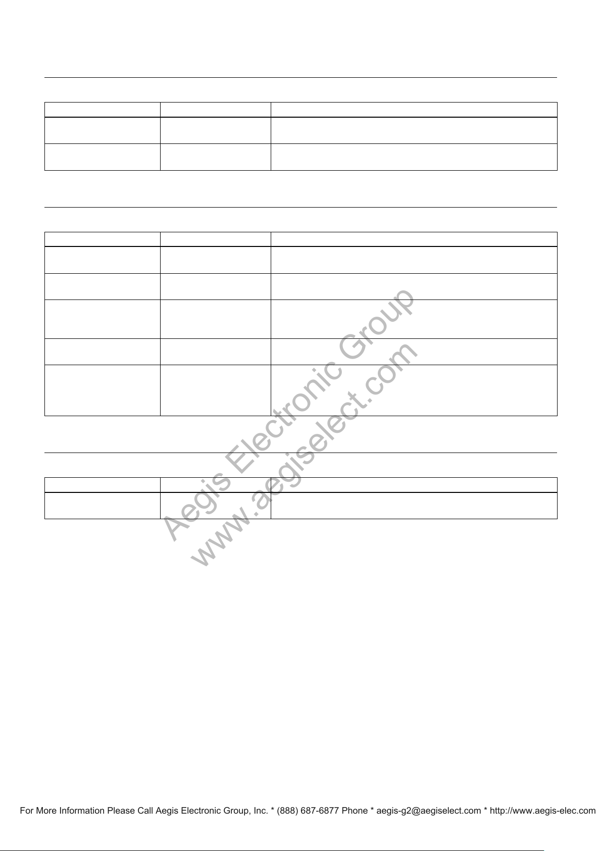
VISCA Camera-Issued Messages
ACK/Completion Messages
Command Messages Comments
ACK z0 4y FF
ket No.)
(y:Soc
Completion z0 5y FF
ket No.)
(y:Soc
z = Device address + 8
Error Messages
Command Messages Comments
Syntax Error z0 60 02 FF Returned when the command format is different or when a command with illegal
Command Buffer Full z0 60 03 FF Indicates that two sockets are already being used (executing two commands) and the
Command Canceled z0 6y 04 FF
(y:Socket N
No Socket z0 6y 05 FF
(y:Socket N
Command Not Executable z0 6y 41 FF
(y:Executio
Socket No. Inquiry
command:0)
o.)
o.)
n command
Returned when the command is accepted.
Returned when the command has been executed.
command parameters is accepted.
command could not be accepted when received.
Returned when a command which is being executed in a socket specified by the
cancel command is canceled. The completion message for the command is not
returned.
Returned when no command is executed in a socket specified by the cancel
command, or when an invalid socket number is specified.
Returned when a command cannot be executed due to current conditions. For
example, when commands controlling the focus manually are received during auto
focus.
z = Device address + 8
Network Change Message
Command Message Comments
Network Change z0 38 FF Issued when power is being routed to the camera, or when the VISCA device is
connected to or disconnected from the VISCA OUT connector.
z = Device address + 8
28
Page 29
EVI-D80N/D80P/D90N/D90P Commands
Aegis Electronic Group
www.aegiselect.com
For More Information Please Call Aegis Electronic Group, Inc. * (888) 687-6877 Phone * [email protected] * http://www.aegis-elec.com
EVI-D80N/D80P/D90N/D90P Command List (1/3)
Command Set Command Command Packet Comments
AddressSet Broadcast 88 30 01 FF Addr
IF_Clear Broadcast 88 01 00 01
CommandCancel 8x 2p FF p: So
CAM_Power On 8x 01 04 00
Off 8x 01 04 00
CAM_Zoom Stop 8x 01 04 07
Tele (Standard) 8x 01 04 07 02 FF
Wide (Standard) 8x 01 04 07 03 FF
Tele (Variable) 8x 01 04 07 2p FF p=0 (Low) to 7 (High)
Wide (Variable) 8x 01 04 07 3p FF
Direct 8x 01 04 47
CAM_DZoom On 8x 01 04 06
Off 8x 01 04 06
CAM_Focus Stop 8x 01 04 08
Far (Standard) 8x 01 04 08 02 FF
Near (Standard) 8x 01 04 08 03 FF
Far (Variable) 8x 01 04 08 2p FF p=0 (Low) to 7 (High)
Near (Variable) 8x 01 04 08 3p FF
Direct 8x 01 04 48
Auto Focus 8x 01 04 38 02 FF AF ON/OFF
Manual Focus 8x 01 04 38 03 FF
Auto/Manual 8x 01 04 38
One Push Trigger 8x 01 04 18 01 FF One Push AF Trigger
Infinity 8x 01 04 18
Near Limit 8x 01 04 28 0p 0q 0r 0s FF pqrs: Focus Near Limit Position
AF Sensitivity
CAM_AFMode Normal AF 8x
CAM_IRCorrection Standard 8x 01 04 11 00 FF FOCUS IR compensation data switching
CAM_ZoomFocus Direct 8x 01 04 47
CAM_WB Auto 8x 01 04 35
CAM_RGain Reset 8x
CAM_BGain Reset 8x 01 04 04
Normal 8x 01 04 58
Low 8x 01 04 58
01 04 57 00 FF AF Movement Mode
Interval AF 8x 01 04 57 01 FF
Zoom Trigger AF 8x 01 04 57 02 FF
Active/Interval Time 8x 01 04 27 0p 0q 0r 0s FF pq: Movement Time, rs: Interval
IR Light 8x 01 04 11 01 FF
Indoor 8x 01 04 35
Outdoor 8x 01 04 35
One Push WB 8x 01 04 35 03 FF One Push WB mode
Manual 8x 01 04 35 05 FF Manual Control mode
One Push Trigger
Up 8x 01 04 03
Down 8x 01 04 03
Direct 8x 01 04 43
Up 8x 01 04 04
Down 8x 01 04 04
Direct 8x 01 04 44
1) 6)
8x 01 04 10 05 FF One Push WB Trigger
FF I/F Clear
02 FF Power ON/OFF
03 FF
00 FF
0p 0q 0r 0s FF pqrs: Zoom Position
02 FF Digital zoom ON/OFF
03 FF
00 FF
0p 0q 0r 0s FF pqrs: Focus Position
10 FF
02 FF Forced infinity
02 FF AF Sensitivity High/Low
03 FF
0p 0q 0r 0s 0t 0u 0v 0w FFpqrs: Zoom Position
00 FF Normal Auto
01 FF Indoor mode
02 FF Outdoor mode
01 04 03 00 FF Manual Control of R Gain
02 FF
03 FF
00 00 0p 0q FF pq: R Gain
00 FF Manual Control of B Gain
02 FF
03 FF
00 00 0p 0q FF pq: B Gain
ess setting
cket No. (=1 or 2)
tuvw: Focus Position
Command List
29
Page 30
30
Command List
EVI-D80N/D80P/D90N/D90P Command List (2/3)
Aegis Electronic Group
www.aegiselect.com
For More Information Please Call Aegis Electronic Group, Inc. * (888) 687-6877 Phone * [email protected] * http://www.aegis-elec.com
Command Set Command Command Packet Comments
CAM_AE Full Aut
CAM_SlowShutter Auto 8x 01 04 5A
CAM_Shutter Reset 8x 01 04 0A
CAM_Iris Reset 8x 01 04 0B
CAM_Gain Reset 8x 01 04 0C
CAM_Bright Up 8x 01 04 0D
CAM_ExpComp On 8x 01 04 3E
CAM_BackLight On 8x 01 04 33
CAM_WD
CAM_Aperture Reset 8x 01 04 02
CAM_HR On 8x 01 04 52
CAM_NR 8x 01 04 53
5)
o 8x 01 04 39 00 FF Automatic Exposure mode
Manual 8x 01 04 39
Shutter Priority 8x 01 04 39 0A FF Shutter Priority Automatic Exposure mode
Iris Priority 8x 01 04 39 0B FF Iris Priority Automatic Exposure mode
2)
Bright
Manual 8x 01 04 5A
Up 8x 01 04 0A
Down 8x 01 04 0A
Direct 8x 01 04 4A
Up 8x 01 04 0B
Down 8x 01 04 0B
Direct 8x
Up 8x 01 04 0C
Down 8x 01 04 0C
Direct 8x 01 04 4C
AE Gain Limit 8x 01 04 2C 0p FF p: Gain Position (4-F)
Down 8x 01 04 0D
Direct 8x 01 04 4D
Off 8x 01 04 3E
Reset 8x 01 04 0E
Up 8x 01 04 0E
Down 8x 01 04 0E
Direct 8x 01 04 4E
Off 8x 01 04 33
On 8x 01 04 3D 02 FF Wide-D ON/OFF
Off 8x 01 04 3D
Auto On Off 8x 01 04 3D 00 FF Wide dynamic ON/OFF auto switching
On (Ratio Fix) 8x 01 04 3D 01 FF Wide dynamic ON (Fixed exposure ratio mode)
On (Histogram) 8x 01 04 3D 04 FF Wide dynamic ON (Histogram mode)
Refresh 8x 01 04 10
Set Parameter 8x 01 04 2D 0p 0q 0r 0s 0t 0u 00 00 FFp: Screen di
Up 8x 01 04 02
Down 8x 01 04 02
Direct 8x 01 04 42
Off 8x 01 04 52
8x 01 04 39 0D FF Bright Mode (Manual control)
03 FF Manual Control mode
02 FF Auto Slow Shutter ON/OFF
03 FF
00 FF Shutter Setting
02 FF
03 FF
00 00 0p 0q FF pq: Shutter Position
00 FF Iris Setting
02 FF
03 FF
01 04 4B 00 00 0p 0q FF pq: Iris Position
00 FF Gain Setting
02 FF
03 FF
00 00 0p 0q FF pq: Gain Position
02 FF Bright Setting
03 FF
00 00 0p 0q FF pq: Bright Position
02 FF Exposure Compensation ON/OFF
03 FF
00 FF Exposure Compensation Amount Setting
02 FF
03 FF
00 00 0p 0q FF pq: ExpComp Position
02 FF Back Light Compensation ON/OFF
03 FF
03 FF
0D FF Wide dynamic Refresh
( 0: Combined image, 2: Long-time, 3: Short-time )
q: Detection sensitivity (0: L 1: M 2: H)
r: Blocked-up shadow correction level (0: L 1: M 2: H 3: S)
s: Blown-out highlight correction level (0: L 1: M 2: H)
tu: Exposure ratio of short exposure (x1 to x64)
00 FF Aperture Control
02 FF
03 FF
00 00 0p 0q FF pq: Aperture Gain
02 FF High-Resolution Mode ON/OFF
03 FF
0p FF p: NR Setting (0: OFF, level 1 to 5)
splay
Page 31
EVI-D80N/D80P/D90N/D90P Command List (3/3)
Aegis Electronic Group
www.aegiselect.com
For More Information Please Call Aegis Electronic Group, Inc. * (888) 687-6877 Phone * [email protected] * http://www.aegis-elec.com
Command Set Command Command Packet Comments
CAM_PictureEffect Off 8x 01 04 63
Neg.Art 8x 01 04 63
B&W 8x 01 04 63
CAM_ICR
CAM_AutoICR
CAM_Memory Reset
CAM_IDWrite 8x 01 04 22
SYS_Menu Off 8x 01 06 06
IR_Receive On 8x 01 06 08
IR_ReceiveReturn On 8x 01 7D 01
Information Display On 8x 01 7E 01
Pan-tiltDrive Up
Pan-tiltLimitSet LimitSet 8x 01 06 07
5)
5)
On 8x 01 04 01 02 FF Infrared Mode ON/OFF
Off 8x 01 04 01
On 8x 01 04 51 02 FF Auto dark-field mode On/Off
Off 8x 01 04 51
Threshold 8x 01 04 21
3) 6)
3) 6)
Set
3) 4)
Recall
Off 8x 01 06 08
On/Off 8x 01 06 08
Off 8x 01 7D 01
Off 8x 01 7E 01
3)
3)
Down
3)
Left
3)
Right
3)
UpLeft
3)
UpRight
DownLeft
DownRight
Stop
AbsolutePosition 8x 01 06 02
RelativePosition 8x 01 06 03
Home 8x 01 06 04
Reset 8x 01 06 05
LimitClear 8x 01 06 07 01 0W
3)
3)
3)
8x 01 04 3F 00 0p FF p: Memory Number (=0 to 5)
8x 01 04 3F 01 0p FF
8x 01 04 3F 02 0p FF
8x 01 06 01 VV WW 03 01 FF VV: Pan speed 01 to 18
8x 01 06 01 VV WW 03 02 FF
8x 01 06 01 VV WW 01 03 FF
8x 01 06 01 VV WW 02 03 FF
8x 01 06 01 VV WW 01 01 FF
8x 01 06 01 VV WW 02 01 FF
8x 01 06 01 VV WW 01 02 FF
8x 01 06 01 VV WW 02 02 FF
8x 01 06 01 VV WW 03 03 FF
0Y 0Y 0Y 0Y 0Z 0Z 0Z 0Z FF
0Y 0Y 0Y 0Y 0Z 0Z 0Z 0Z FF
0Y 0Y 0Y 0Y 0Z 0Z 0Z 0Z FF
07 0F 0F 0F 07 0F 0F 0F FF
00 FF Picture Effect Setting
02 FF
04 FF
03 FF
03 FF
00 00 0p 0q FF pq: ICR ON → OFF Threshold Level
Corresponds to 1 to 6 on the Remote Commander.
0p 0q 0r 0s FF pqrs: Camera ID (=0000 to FFFF)
03 FF Turns off the menu screen.
02 FF IR(remote commander) receive ON/OFF
03 FF
10 FF
03 00 00 FF IR (remote commander) receive message via the VISCA
communication ON/OFF
13 00 00 FF For contents of messages, see page 33.
18 02 FF ON/OFF of the Operation status display of One Push
18 03 FF Trigger of CAM_Memory and CAM_WB
WW: Tilt Speed 01 to 17
YYYY: Pan Position E1E5 to 1E1B (center 0000)
ZZZZ: Tilt Position FC75 to 0FF0 (IMAGE FLIP: OFF)
(center 0000)
Tilt Position F010 to 038B (IMAGE FLIP: ON)
(center 0000)
See page 42
VV WW
VV WW
FF
FF
00 0W
W: 1 UpRight
YYYY: Pan Limit Position 0001 to 1E1B
ZZZZ: Tilt Limit Position 0001 to 0FF0 (IMAGE FLIP: OFF)
Tilt Limit Position 0001 to 038B (IMAGE FLIP: ON)
W: 0 DownLeft
YYYY: Pan Limit Position E1E5 to FFFF
ZZZZ: Tilt Limit Position FC75 to FFFF (IMAGE FLIP: OFF)
Tilt Limit Position F010 to FFFF (IMAGE FLIP: ON)
Command List
1) After an ACK to a One Push White Balance Trigger is sent until the operation is completed, “Not Executable” is sent as a reply when any
other commands are received.
2) Bright can be set only in Full Auto mode or Shutter Priority mode.
3) When the menu is displayed, this operation is ignored.
4) When other commands are received after a Completion notification for the Recall command is sent, “Command not executable” may be
returned for a maximum of 240 msec due to internal processing. In this case, please transmit the command again.
5) The command is available on EVI-D90N/P only.
6) If Information Display is set to ON, the next command action may be delayed due to Operation status display internal processing after
these commands are executed.
31
Page 32
32
Command List
EVI-D80N/D80P/D90N/D90P Inquiry Command List (1/2)
Aegis Electronic Group
www.aegiselect.com
For More Information Please Call Aegis Electronic Group, Inc. * (888) 687-6877 Phone * [email protected] * http://www.aegis-elec.com
Inquiry Command Command Packet Inquiry Packet Comments
CAM_PowerInq 8x 09 04 00
CAM_ZoomPosInq 8x 09 04 47
CAM_DZoomModeInq 8x 09 04 06
CAM_FocusModeInq 8x 09 04 38
CAM_FocusPosInq 8x 09 04 48
CAM_FocusNearLimitInq 8x 09 04 28
CAM_AFSensitivityInq 8x 09 04 58
CAM_AFModeInq 8x 09 04 57
CAM_AFTimeSettingInq 8x 09 04 27
CAM_IRCorrectionInq 8x 09 04 11
CAM_WBModeInq 8x 09 04 35
CAM_RGainInq 8x 09 04 43
CAM_BGainInq 8x 09 04 44
CAM_AEModeInq 8x 09 04 39
CAM_SlowShutterModeInq 8x 09 04
CAM_ShutterPosInq 8x 09 04 4A
CAM_IrisPosInq 8x 09 04 4B
CAM_GainPosInq 8x 09 04 4C
CAM_AEGainLimitInq 8x 09 04 2C
CAM_BrightPosInq 8x 09 04 4D
CAM_ExpCompModeInq 8x 09 04 3E
CAM_ExpCompPosInq 8x 09 04 4E
CAM_BackLightModeInq 8x 09 04 33
CAM_WDModeInq
1)
8x 09 04 3D FF y0 50 02 FF On
FF y0 50 02 FF On
y0 50 03 FF Off
FF y0 50 0p 0q 0r 0s FF pqrs: Zoom Position
FF y0 50 02 FF D-Zoom On
y0 50 03 FF D-Zoom Off
FF y0 50 02 FF Auto Focus
y0 50 03 FF Manual Focus
FF y0 50 0p 0q 0r 0s FF pqrs: Focus Position
FF y0 50 0p 0q 0r 0s FF pqrs: Focus Near Limit Position
FF y0 50 02 FF AF Sensitivity Normal
y0 50 03 FF AF Sensitivity Low
FF y0 50 00 FF Normal AF
y0 50 01 FF Interval AF
y0 50 02 FF Zoom Trigger AF
FF y0 50 0p 0q 0r 0s FF pq: Movement Time, rs: Interval
FF y0 50 00 FF Standard
y0 50 01 FF IR Light
FF y0 50 00 FF Auto
y0 50 01 FF In Door
y0 50 02 FF Out Door
y0 50 03 FF One Push WB
y0 50 05 FF Manual
FF y0 50 00 00 0p 0q FF pq: R Gain
FF y0 50 00 00 0p 0q FF pq: B Gain
FF y0 50 00 FF Full Auto
y0 50 03 FF Manual
y0 50 0A FF Sh
y0 50 0B FF Iris Priority
y0 50 0D FF Bright
5A FF y0 50 02 FF Auto
y0 50 03 FF Manual
FF y0 50 00 00 0p 0q FF pq: Shutter Position
FF y0 50 00 00 0p 0q FF pq: Iris Position
FF y0 50 00 00 0p 0q FF pq: Gain Position
FF y0 50 0p FF p: Gain Limit
FF y0 50 00 00 0p 0q FF pq: Bright Position
FF y0 50 02 FF On
y0 50 03 FF Off
FF y0 50 00 00 0p 0q FF pq: ExpComp Position
FF y0 50 02 FF On
y0 50 03 FF Off
y0 50 03 FF Off
y0 50 00 FF Au
y0 50 01 FF On (Ratio Fix)
y0 50 04 FF On (Histogram mode)
utter Priority
to On Off
Page 33
EVI-D80N/D80P/D90N/D90P Inquiry Command List (2/2)
Aegis Electronic Group
www.aegiselect.com
For More Information Please Call Aegis Electronic Group, Inc. * (888) 687-6877 Phone * [email protected] * http://www.aegis-elec.com
Inquiry Command Command Packet Inquiry Packet Comments
1)
q
oldInq
1)
1)
CAM_WDParameterInq
CAM_ApertureInq 8x 09 04 42
CAM_HRModeInq 8x 09 04 52
CAM_NRInq 8x 09 04 53
CAM_PictureEffectModeInq 8x 09 04 63
CAM_ICRM
CAM_AutoICRModeIn
CAM_AutoICRThresh
CAM_IDInq 8x 09 04 22
CAM_VersionInq 8x 09 00 02
Information Display 8x 09 7E 01 18 FF y0 50 02 FF On
IR_R
IR_ReceiveReturn y0 07 7D 01
IR_ConditionInq 8x 09 06 34
Pan-tiltMaxSpeedInq 8x 09 06 11
Pan-tiltPosInq
Pan-tiltModeInq 8x 09 06 10
1) The command is available on EVI-D90N/P only.
2) If a Pan-tiltPosInq command is received after Pan-tiltDrive Reset, the pan/tilt position may be different for 1-2 addresses.
odeInq
eceive 8x 09 06 08
2)
8x 09 04 2D FF y0 50 0p 0q 0r 0s 0t 0u 00 00 FF p: Screen display
q: Detection sensitivity
r: Blocked-up shadow correction level
s: Blown-out highlight correction level
tu: Exposure ratio of short exposure
FF y0 50 00 00 0p 0q FF pq: Aperture Gain
FF y0 50 02 FF On
y0 50 03 FF Off
FF y0 50 0p FF p: NR level
FF y0 50 00 FF Off
y0 50 02 FF Neg.Art
y0 50 04 FF B&W
8x 09 04 01 FF y0 50 02 FF On
y0 50 03 FF Off
8x 09 04 51 FF y0 50 02 FF On
y0 50 03 FF Off
1)
8x 09 04 21 FF y0 50 00 00 0p 0q FF pq: ICR ON → OFF Threshold Level
FF y0 50 0p 0q 0r 0s FF pqrs: Camera ID
FF y0 50 00 01
mn pq rs tu vw FF
y0 50 03 FF Off
FF y0 50 02 FF On
y0 50 03 FF Off
04 00 FF Power ON/OFF
y0 07 7D 01 04 07 FF Zoom tele/wide
y0 07 7D 01 04 38 FF AF On/Off
y0 07 7D 01 04 33 FF
y0 07
7D 01 04 3F FF CAM_Memory
y0 07 7D 01
FF y0 50 00 FF
y0 50 01 FF
y0 50 02 FF Impossible to detect the infrared signals from
FF y0 50 ww zz FF ww = Pan Max Speed
8x 09 06 12 FF y0 50 0w 0w 0w 0w
0z 0z 0z 0z FF
FF y0 50 pq rs FF pqrs: Pan-tilt Status
06 01 FF Pan_tiltDrive
mnpq: Model Code (D80:050C/D90:050D)
rstu: ROM version
vw: Socket Number (=02)
See page 23.
CAM_Backlight
Stable reception from the IR Remote Commander
Unstable reception from the IR Remote Commander
the Remote Commander because the camera is
turned on by the Remote Commander.
xx = Tilt Max Speed
wwww = Pan Position
zzzz = Tilt Position Speed
See page 42.
See page 42.
Command List
33
Page 34
34
Command List
EVI-D80N/D80P/D90N/D90P Block Inquiry Command List
Aegis Electronic Group
www.aegiselect.com
For More Information Please Call Aegis Electronic Group, Inc. * (888) 687-6877 Phone * [email protected] * http://www.aegis-elec.com
Lens Control System Inquiry Commands ............ Command Packet 8x 09 7E 7E 00 FF
Byte Bit Comments
7
6
5
4
0
3
2
1
0
7 0 Completion Message (50h)
6 1
5 0
4 1
1
3 0
2 0
1 0
0 0
7 0
6 0
5 0
4 0
2
3
2
1
0
7 0
6 0
5 0
4 0
3
3
2
1
0
7 0
6 0
5 0
4 0
4
3
2
1
0
7 0
6 0
5 0
4 0
5
3
2
1
0
Destination
Source Addres
Posit
Zoom
Zoom Posit
Zoom Posit
Zoom Posit
Address
ion (HH)
ion (HL)
ion (LH)
ion (LL)
Byte Bit Comments
7 0
6 0
5 0
4 0
6
3
s
2
1
0
7 0
6 0
5 0
4 0
7
3
2
1
0
7 0
6 0
5 0
4 0
8
3
2
1
0
7 0
6 0
5 0
4 0
9
3
2
1
0
7 0
6 0
5 0
4 0
10
3
2
1
0
7 0
6 0
5 0
4 0
11
3
2
1
0
Focus Ne
Focus Ne
Focus Posi
Focus Posi
Focus Posi
Focus Posi
ar Limit (H)
ar Limit (L)
tion (HH)
tion (HL)
tion (LH)
tion (LL)
Byte Bit Comments
7 0
6 0
5 0
4 0
12
3 0
2 0
1 0
0 0
7 0
6 0
5 0
430: Normal
13
14
15
2: Zoom Trigger
AF Sensitiv
2
1: Normal
1 Digital Zoom 1:On 0:Off
0 Focus
7 0
6 0
5 0
4 0
Low Cont
3
0: No
Camera Memo
2
1: Executing 0: Stopped
Focus Co
1
0: Stopped
Zoom Comm
0
0: Stopped
7 1 Terminator (FFh)
6 1
5 1
4 1
3 1
2 1
1 1
0 1
1: Interval
ity 0: Slow
Mode 0:Manual 1:Auto
rast Detection 1: Yes
ry Recall
mmand 1: Executing
and 1: Executing
Page 35
Lens Control System Inquiry Commands ............ Command Packet 8x 09 7E 7E 01 FF
Aegis Electronic Group
www.aegiselect.com
For More Information Please Call Aegis Electronic Group, Inc. * (888) 687-6877 Phone * [email protected] * http://www.aegis-elec.com
Command List
Byte Bit Comments
7
6
5
4
0
3
2
1
0
7 0 Completion Message (50h)
6 1
5 0
4 1
1
3 0
2 0
1 0
0 0
7 0
6 0
5 0
4 0
2
3
2
1
0
7 0
6 0
5 0
4 0
3
3
2
1
0
7 0
6 0
5 0
4 0
4
3
2
1
0
7 0
6 0
5 0
4 0
5
3
2
1
0
D
estination
Source Addres
R
Gain (H)
R Ga
B
in (H)
Ga
B
Ga
Address
in (L)
in (L)
Byte Bit Comments
7 0
6 0
5 0
4 0
6
3
s
2
1
0
7 0
6 0
5 0
4 0
7
3
2
1
0
7 0
6 0
5 0
4
8
3
2
1
0
7 0
6 0
igh-Resolution 1: On 0: Off
5 H
Wide-D (1: Oth
4
9
10
11
0: Off)
3 0
ack Light 1:On 0:Off
2 B
1 Exposure C
0 Slow Shu
7 0
6 0
5 0
4
3
2
1
0
7 0
6 0
5 0
4
3
2
1
0
WB Mode
e Ga
pertur
A
Exposure Mo
omp. 1:On 0:Off
tter 1:Auto 0:Manual
utter P
Sh
Iris Posit
in
de
er than Off,
osition
ion
Byte Bit Comments
7 0
6 0
5 0
4 0
12
3
2
1
0
7 0
6 0
5 0
4
13
3
2
1
0
7 0
6 0
5 0
4 0
14
3
2
1
0
7 1 Terminator (FFh)
6 1
5 1
4 1
15
3 1
2 1
1 1
0 1
Gain Position
B
right Posi
Exposure Co
tion
mp. Position
35
Page 36
36
Command List
Aegis Electronic Group
www.aegiselect.com
For More Information Please Call Aegis Electronic Group, Inc. * (888) 687-6877 Phone * [email protected] * http://www.aegis-elec.com
Other Inquiry Commands .............................................. Command Packet 8x 09 7E 7E 02 FF
Byte Bit Comments
7
6
5
4
0
3
2
1
0
7 0 Completion Message (50h)
6 1
5 0
4 1
1
3 0
2 0
1 0
0 0
7 0
6 0
5 0
4 0
2
3 0
2 Auto
1 0
0 Power 1:
7 0
6 Stabilizer
5 0
4 ICR 1: On
3
3 0
2 0
1 0
0 0
7 0
6 0
5 0
4 Inconsist
4
3 Inconsistent
2 Inconsistent
1 0
0 0
7 0
6 0
5 0
4 0
5
3
2
1
0
Destination
ICR 1: On 0: Off
On 0: Off
(1: On, 0: Off)
Picture Eff
Address
Source Addres
0: Off
ect Mode
ent
Byte Bit Comments
7 0
6 0
5 0
4 0
6
3 0
s
2 0
1 0
0 0
7 0
6 0
5 0
4 0
7
3 0
2 0
1 0
0 0
7 0
6 0
5 0
4 0
8
3
2
1
0
7 0
6 0
5 0
4 0
9
3
2
1
0
7 0
6 0
5 0
4 0
10
3
2
1
0
7 0
6 0
5 0
4 0
11
3
2
1
0
Camera ID (HH)
amera ID (HL)
C
amera ID (LH)
C
amera ID (LL)
C
Byte Bit Comments
7 0
6 0
5 Inconsistent
Memory 1:
4
provided
12
3 Inconsistent
ICR 1: Pro
2
provided
Stabilizer (1:
1
provided)
0 System 1:PAL 0:NTSC
7 0
6 0
5 0
4 0
13
3
2
1
0
7 0
6 0
5
4
14
3
2
1
0
7 1 Terminator (FFh)
6 1
5 1
4 1
15
3 1
2 1
1 1
0 1
Provided 0: Not
vided 0: Not
Provided, 0: Not
ent
Inconsist
Inconsistent
Page 37
Command List
Aegis Electronic Group
www.aegiselect.com
For More Information Please Call Aegis Electronic Group, Inc. * (888) 687-6877 Phone * [email protected] * http://www.aegis-elec.com
Enlargement Function1 Query Command .................... Command Packet 8x 09 7E 7E 03 FF
Byte Bit Comments
7
6
5
4
0
3
2
1
0
7 0 Completion Message (50h)
6 1
5 0
4 1
1
3 0
2 0
1 0
0 0
7 0
6 0
5 0
4 0
2
3 0
2 0
1 0
0 0
7 0
6 0
5 0
4 0
3
3 0
2 0
1 0
0 0
7 0
6 0
5 0
4 0
4
3
2
1
0
7 0
6 0
5 0
4 0
5
3
2
1
0
Destination
Source Addres
Activat
AF
AF Activat
Address
ion Time (H)
ion Time (L)
Byte Bit Comments
7 0
6 0
5 0
4 0
6
3
s
2
1
0
7 0
6 0
5 0
4 0
7
3
2
1
0
7 0
6 0
5 0
4 0
8
3 1
2 0
1 0
0 0
7 0
6 0
5 0
4 0
9
3 1
2 0
1 0
0 0
7 0
6 0
5 0
4 0
10
3 0
2 0
1 0
0 0
AF Interval
AF Interval
Time (H)
Time (L)
Byte Bit Comments
7 0
6 0
5 0
4 0
11
3 0
2 1
1 1
0 1
7 0
6 0
5 0
4 0
12
3 0
2 0
1 0
0 1
7 0
6 0
5 0
4 0
13
3 0
2
1
0
7 0
6 0
5 0
4 0
14
3
2
1
0
1 Terminator (FFh)
7
6 1
5 1
4 1
15
3 1
2 1
1 1
0 1
NR Level
Gain Limit
AE
37
Page 38
38
Command List
Aegis Electronic Group
www.aegiselect.com
For More Information Please Call Aegis Electronic Group, Inc. * (888) 687-6877 Phone * [email protected] * http://www.aegis-elec.com
Enlargement Function2 Query Command .................... Command Packet 8x 09 7E 7E 04 FF
Byte Bit Comments
7
6
5
4
0
3
2
1
0
7 0 Completion Message (50h)
6 1
5 0
4 1
1
3 0
2 0
1 0
0 0
7 0
6 0
5 0
4 0
2
3 0
2
1
0
7 0
6 0
5 0
4 0
3
3
2
10WideD detectio
7 0
6 0
5 0
4 0
4
32W
10WideD blown-ou
7 0
6 0
5 0
4 0
5
3
2
1
0
D
estination
W
ideD mode (0:
2: Auto ON/OFF, 3: ON
(RatioFIx), 4: ON (Dver))
WideD screen
0: Combined image
1: Long/short division
2: Long-time 3: Short-time
0: L 1: M 2: H
ideD blocke
correction level 0: L 1: M 2: H 3: S
correction level 0: L 1: M 2: H
W
ideD short
Exposure ratio (H)
Address
Source Addres
OFF, 1: ON,
display
n sensitivity
d-up shadow
t highlight
exposure
s
Byte Bit Comments
7 0
6 0
5 0
4 0
6
3
2
WideD short
1
Exposure ratio (L)
0
7 0
6 0
5 0
4 0
7
3 0
2 0
1 0
0 0
7 0
6 0
5 0
4 0
8
3 0
2 0
1 0
0 0
7 0
6 0
5 0
4 0
9
3 0
2 0
1 0
0 0
7 0
6 0
5 0
4 0
10
3 0
2 0
1 0
0 0
7 0
6 0
5 0
4 0
11
3 0
2 0
1 0
0 0
exposure
Byte Bit Comments
7 0
6 0
5 0
4 0
12
3 0
2 0
1 0
0 0
7 0
6 0
5 0
4 0
13
3 0
2 0
1 0
0 0
7 0
6 0
5 0
4 0
14
3 0
2 0
1 0
0 0
7 1 Terminator (FFh)
6 1
5 1
4 1
15
3 1
2 1
1 1
0 1
Page 39
VISCA Command Setting Values
Aegis Electronic Group
www.aegiselect.com
For More Information Please Call Aegis Electronic Group, Inc. * (888) 687-6877 Phone * [email protected] * http://www.aegis-elec.com
Command List
Exposure Control (1/2)
NTSC (s) PAL (s)
Shutter Speed 15 1/10000 1/10000
14 1/6000 1/6000
13 1/4000 1/3500
12 1/3000 1/2500
11 1/2000 1/1750
10 1/1500 1/1250
0F 1/1000 1/1000
0E 1/725 1/600
0D 1/500 1/425
0C 1/350 1/300
0B 1/250 1/215
0A 1/180 1/150
09 1/125 1/120
08 1/100 1/100
07 1/90 1/75
06 1/60 1/50
05 1/30 1/25
04 1/15 1/12
03 1/8 1/6
02 1/4 1/3
01 1/2 1/2
00 1/1 1/1
Iris 11 F1.4 (F1.35)
10 F1.6
0F F2
0E F2.4
0D F2.8
0C F3.4
F4
* Number in
0B
0A F4.8
09 F5.6
08 F6.8
07 F8
06 F9.6
05 F11
04 F14
03 F16
02 F19
01 F22
00 CLOSE
( ) applies to EVI-D90N/P only.
Gain 0F +28 dB
0E +26 dB
0D +24 dB
0C +22 dB
+20 dB
+18 dB
dB
+14 dB
dB
dB
dB
dB
dB
dB
dB
+28 dB
+20 dB
+18 dB
dB
dB
+14
dB
dB
dB
Limit 0F
Gain
0B
0A
09 +16
08
07 +12
06 +10
05 +8
04 +6
03 +4
02 +2 dB
01 0
00 –3
0E +26 dB
0D +24 dB
0C +22 dB
0B
0A
09 +16
08
07 +12 dB
06 +10
05 +8
04 +6
39
Page 40
40
Command List
Aegis Electronic Group
www.aegiselect.com
For More Information Please Call Aegis Electronic Group, Inc. * (888) 687-6877 Phone * [email protected] * http://www.aegis-elec.com
Exposure Control (2/2)
IRIS GAIN
Bright 1F F1.4 (F1.35) +28 dB
1E F1.4 (F1.35)
1D F1.4 (F1.35)
1C F1.4
1B F1.4
1A F1.4
19 F1.4 (F1.35) +16 dB
18 F1.4
17 F1.4
16 F1.4
15 F1.4
14 F1.4
13 F1.4 (F1.35) +4 dB
12 F1.4
11 F1.4
10 F1.6 0
0F F2 0 dB
0E F2.4 0
0D F2.8 0 dB
0C F3.4 0
0B F4 0
0A F4.8 0
09 F5.6 0 dB
08 F6.8 0
07 F8 0
06 F9.6 0
05 F11 0
04 F14 0
03 F16 0 dB
02 F19 0
01 F22 0
00 CLOS
Exposure Comp. 0E +7 +10.5 dB
0D +6 +9 dB
0C +5 +7.5
0B +4 +6
0A +3 +4.5
09 +2 +3
08 +1 +1.5 dB
07 0 0
06 –1 –1.5
05 –2 –3
04 –3 –4.5
03 –4 –6 dB
02 –5 –7.5
01 –6 –9
00 –7 –10.5
*
Number in
( ) applies to EVI-D90N/P only.
(F1.35) +22 dB
(F1.35) +20 dB
(F1.35) +18 dB
(F1.35) +14 dB
(F1.35) +12 dB
(F1.35) +10 dB
(F1.35) +8 dB
(F1.35) +6 dB
(F1.35) +2 dB
(F1.35) 0 dB
E 0
+26 dB
+24 dB
dB
dB
dB
dB
dB
dB
dB
dB
dB
dB
dB
dB
dB
dB
dB
dB
dB
dB
dB
dB
dB
dB
dB
dB
Zoom Ratio and Zoom Position (for reference)
(EVI-D80N/P)
Zoom Ratio
×36 Lens
×1 0000
×2 1804
×3 2296
×4 28F0
×5 2D58
×6 30AA
×7 3350
×8 357E
×9 3758
×10 38EF
×11 3A52
×12 3B84
×13 3C90
×14 3D7A
×15 3E42
×16 3EEE
×17 3F82
×18 4000
Optical Zoom
Positon Data
Zoom Ratio and Zoom Position (for reference)
(EVI-D90N/P)
Zoom Ratio
×36 Lens
×1 0000
×2 15CA
×3 1F65
×4 2527
×5 2921
×6 2C22
×7 2E88
×8 3088
×9 3242
×10 33C9
×11 3529
×12 366C
×13 3795
×14 38A8
×15 39A5
×16 3A8E
×17 3B61
×18 3C1E
×19 3CC7
×20 3D5C
×21 3DDE
×22 3E50
×23 3EB3
×24 3F09
×25 3F53
×26 3F94
×27 3FCD
×28 4000
Optical Zoom
Positon Data
Page 41
Command List
Aegis Electronic Group
www.aegiselect.com
For More Information Please Call Aegis Electronic Group, Inc. * (888) 687-6877 Phone * [email protected] * http://www.aegis-elec.com
X12-NTSC/PAL
Digital Zoom
Ratio
×1 4000
×2 6000
×3 6A80
×4 7000
×5 7300
×6 7540
×7 76C0
×8 7800
×9 78C0
×10 7980
×11 7A00
×12 7AC0
Digital Zoom
Position Data
Lens control (EVI-D80N/P)
0000 to 4000 to 7AC0
Zoom Position
Focus Position
Focus Near
Limit
Wide end Optical Digital
Tele end Tele end
1000 to C000*
Far end Near end
* Depending
1000: Over Inf
2000: 8 m
3000: 3.5 m
4000: 2 m
5000: 1.4 m
6000: 1 m
7000: 80 cm
8000: 29 cm
9000: 10 cm
A000: 4.7 cm
B000: 2.3 cm
C000: 1 cm
on the Focus Near Limit setting.
As the distance on the left
will differ due to temperature
characteristics, etc., use as
approximate values.
* The lower 1 byte is fixed at 00.
Lens control (EVI-D90N/P)
0000 to 4000 to 7AC0
Zoom Position
Wide end Optical Digital
Tele end Tele end
1000 to C000*
Focus Position
Focus Near
Limit
Far end Near end
* Depending
1000: Over Inf
12 m
2000:
3000: 5.6 m
4000: 4 m
5000: 2.7 m
6000: 2 m
7000: 1.5 m
8000: 80 cm
9000: 30 cm
A000: 19 cm
B000: 9 cm
C000: 1 cm
on the Focus Near Limit setting.
As the distance on the left
will differ due to temperature
characteristics, etc., use as
approximate values.
* The lower 1 byte is fixed at 00.
Others
AF Active Time
AF Interval Time
R Gain 00 to FF
B Gain 00 to FF
erture L
Ap
NR Level 00 t
AutoICR ON
OFF Threshold
1)
Unit: One second
1)
1)
00 to FF
00 to FF
evel 00 to 0F
o 05
00 to 1C
Level
41
Page 42
Pan/Tilt Status Code List
Aegis Electronic Group
www.aegiselect.com
For More Information Please Call Aegis Electronic Group, Inc. * (888) 687-6877 Phone * [email protected] * http://www.aegis-elec.com
P Q R S
- - - - - - - - 0 - - - - - - 1 A Pan movement all the way to the left
- - - - - - - - 0 - - - - - 1 - A Pan movement all the way to the right
- - - - - - - - 0 - - - - 1 - - A Tilt movement all the way up
- - - - - - - - 0 - - - 1 - - - A Tilt movement all the way down
- - - - - - - - - - 0 0 - - - - Pan movement is correct
- - - - - - - - - - 0 1 - - - - Pan position cannot be detected
- - - - - - 0 0 0 - - - - - - - The Tilt movement is correct
- - - - - - 0 1 0 - - - - - - - The Tilt position cannot be detected
- - - - 0 0 - - 0 - - - - - - - No movement instructions
- - - - 0 1 - - 0 - - - - - - - In the midst of a Pan/Tilt
- - - - 1 0 - - 0 - - - - - - - Pan/Tilt completed
- - - - 1 1 - - 0 - - - - - - - Pan/Tilt failed
- - 0 0 - - - - 0 - - - - - - - Not initialized
- - 0 1 - - - - 0 - - - - - - - Initializing
- -1 0 - -
- -1 1 - - - - 0 - - - - - - - Initialization failed
( - : optional)
- - 0 - - - - - - - Initialization completed
Command List
Pan/Tilt Position (for reference)
Parameter (position)
PAN E1E5 (-170 degree) to 1E1B (+170 degree)
TILT FC75 (-20 de
F010 (-90 degree) to 038B (+20 degree) (IMAGE FLIP: ON)
gree) to 0FF0 (+90 degree) (IMAGE FLIP: OFF)
LED Status
Status POWER (Green) STANDBY (Orange)
Main power ON Power On (including ini
When receiving infrared signals form Remote Commander Blinking Off
At position
status
Standby
Power off by VISCA or the Remote Commander
Main power Off Off Off
Initialization
error
BOTTOM
switch
Pan/tilt er
Internal error(LSI, etc.) Blinking alternately
Setting err
(Example: when the BOTTOM switch 5 is set to ON.)
ror Blinking Blinking
or
tializing period) On Off
detection error On Blinking
Off On
On On
42
Page 43
D70 Mode
Aegis Electronic Group
www.aegiselect.com
For More Information Please Call Aegis Electronic Group, Inc. * (888) 687-6877 Phone * [email protected] * http://www.aegis-elec.com
Overview
The D70 mode allows you to control the EVI-D80N/
D80P/D90N/D90P using VISCA commands for the
EVI-D70/P. Most of the VISCA commands for the
EVI-D80N/D80P/D90N/D90P correspond to one for
the EVI-D70/P. However, some of the VISCA
commands for the EVI-D80N/D80P/D90N/D90P are
different from those for the EVI-D70/P in definitions
of parameters.
When you send those commands to an EVI-D80N/
D80P/D90N/D90P whose D70 mode is set to ON, the
camera translates the parameters for the EVI-D70/P to
those for the EVI-D80N/D80P/D90N/D90P and
executes the command. The following parameters are
subject to translation.
Zoom posi
Pan-tilt
Pan-tilt
Notes
Even if you set the D70 mode to ON, the EVI-
D80N/D80P/D90N/D90P may not emulate the
EVI-D70/P perfectly. This is caused by differences
in hardware between the two models.
The funct
P but not with the EVI-D80N/D80P/D90N/D90P
cannot be executed.
tion
speed
position
ions that are provided with the EVI-D70/
Switching the Mode
You can switch the D70 mode ON or OFF by switching
the BOTTOM switch at the bottom of the EVI-D80N/
D80P/D90N/D90P. To change the D70 mode setting,
move the BOTTOM switch to ON or OFF while the
camera’s power is off or the camera is in standby mode.
Then, turn the power on by connecting the camera to
an AC outlet or by using the VISCA commands or the
Remote Commander.
It takes about 7-16 seconds for the image to be
displayed after Pan/Tilt initialization motion has
stopped.
Do not t
displayed.
The mode w
setting of the BOTTOM switch after the power has
been turned on.
After you change the mode, previously saved position
preset data will be lost. (Zoom, Pan/Tilt positions, etc.
will be reset to their initial settings.)
urn off DC power until the image has been
ill not change if you change the switch
43
Page 44
Accepting or Sending Back Commands
Aegis Electronic Group
www.aegiselect.com
For More Information Please Call Aegis Electronic Group, Inc. * (888) 687-6877 Phone * [email protected] * http://www.aegis-elec.com
When accepting commands
Type of command D70 mode on D70 mode off
Common to both the D70 and
D80N/D80P/D90N/D90P
Only for the D80N/D80P/D90N/D90P Accepts as is
Only for the D70 Refuses and sends back the SyntaxError message
When accepting inquiry commands
Type of command D70 mode on D70 mode off
Common to both the D70 and
D80N/D80P/D90N/D90P
Only for the D80N/D80P/D90N/D90P Sends back the D80N/D80P/D90N/D90P’s parameters
Only for the D70 Refuses and sends back the SyntaxError message
Common pa
Different parameters Translates the D70’s parameters to those of
CAM_Memory Reset Memorized data items are erased and
Common pa
Different parameters Sends back the D70’s parameters translated from
rameters Accepts as is
Accepts as is
the D80N/D80P/D90N/D90P
Memorized data items are erased
camera settings return to initial values
rameters Sends back parameters common to both the D70 and D80N/D80P/D90N/D90P
Sends back the D80N/D80P/D90N/D90P’s
those of the D80N/D80P/D90N/D90P
parameters
D70 Mode
44
Page 45
Translating Parameters
Aegis Electronic Group
www.aegiselect.com
For More Information Please Call Aegis Electronic Group, Inc. * (888) 687-6877 Phone * [email protected] * http://www.aegis-elec.com
Zoom position
There is no change for EVI-D80N/D80P. EVI-D90N/
D90P employ an 18× optical zoom lens but there are
no translating parameters. The zoom ratio and
corresponding position data are as shown in the table
below (for reference).
Zoom Ratio
× 18 Lens
× 1
× 2
× 3
× 4
× 5
× 6
× 7
× 8
× 9
× 10
× 11
× 12
× 13
× 14
× 15
× 16
× 17
× 18
Optical Zoom
Position Data
0000
1606
2151
2860
2CB5
3060
32D3
3545
3727
38A9
3A42
3B4B
3C85
3D75
3E4E
3EF7
3FA0
4000
D70 Mode
Pan/tilt speed
The actual speed that is defined by the parameters
corresponds to that of the D70.
When the camera receives commands such as
PantiltDrive Home, Reset, or CAM_Memory Recall,
that do not include speed indications, these operations
are carried out at the same speed as they would be
when the D70 mode is set to OFF.
Speed (deg/sec)
Parameters
01h
02h
03h
04h
05h
06h
07h
08h
09h
h
0A
0Bh
0Ch
0Dh
0Eh
0Fh
10h
11h
12h
13h
14h
15h
16h
17h
1)
18h
D80N/
D80P
1.7
2.2
2.9
4.1
6.8
11
16
21
27
31
35
40
42
44
46
48
50
79
81
83
85
87
90
100
1) Max. pan speed is 18h; max. tilt speed is 17h.
D90N/
D90P
1.3
1.7
2.2
3.2
5.4
11
16
21
27
31
35
40
42
44
46
48
50
79
81
83
85
87
90
100
D70
1.7
2.2
2.9
4.1
6.8
11
16
21
27
31
35
40
47
49
54
56
62
64
69
72
79
84
90
100
45
Page 46
D70 Mode
Aegis Electronic Group
www.aegiselect.com
For More Information Please Call Aegis Electronic Group, Inc. * (888) 687-6877 Phone * [email protected] * http://www.aegis-elec.com
Pan/tilt position
Pan position
Cameras Parameters
EVI-D70/P F725h (–170 degrees)
EVI-D80N/D80P/D90N/
D90P
Tilt position
Cameras Parameters
EVI-D70/P FE70h (–30 degrees)
EVI-D80N/D80P/D90N/
D90P
Translation of commands
Accepting parameters
Pan position Multiplies received parameters by 17/5
Tilt position Multiplies received parameters by 17/5
D70 D80N/D80P/D90N/D90P
Pan/Tilt Pan Tilt
F725h
… … –
FEF5h
… … …
FFFDh
FFFEh
FFFFh
0000h
0001h
0002h
0003h
0004h
0005h
0006h
0007h
0008h
0009h
000Ah
000Bh
… … –
04B0h
… … –
08DBh
E1E5h (–170 degrees)
FC75h (–20 degrees)
Translation
to 08DBh (+170 degrees)
to 1E1Bh (+170 degrees)
to 04B0h (+90 degrees)
to 0FF0 (+90 degrees)
E1E5h –
FC75h FC75h
FFF6h FFF6h
FFFAh FFFAh
FFFDh FFFDh
0000h 0000h
0003h 0003h
0006h 0006h
000Ah 000Ah
000Dh 000Dh
0011h 0011h
0014h 0014h
0017h 0017h
001Bh 001Bh
001Eh 001Eh
0022h 0022h
0025h 0025h
0FF0h 0FF0h
1E1Bh –
Example
When you execute the Relative position command
100 times, one step after another to turn the camera to
the right side:
Cameras Results
EVI-D70/P Turns to
EVI-D80N/D80P/D90N/
D90P whose D70
mode is ON
the right side by 7.5 degrees.
Turns to the right side by 6.6 degrees.
For Absolute Position commands, the permissible
range for drive settings are the same as those for the
EVI-D70/P.
Pan direct
ion: –170 degrees to + 170 degrees.
Tilt direction: –20 degrees to + 90 degrees.
Translation when answering inquiry commands
The camera sends back values that are calculated by
inverse conversion performed when the camera accepts
commands.
Note
Repetitive use of the Absolute position command may
increase the variance that is accumulated from
translation.
46
Page 47

Specifications
Aegis Electronic Group
www.aegiselect.com
For More Information Please Call Aegis Electronic Group, Inc. * (888) 687-6877 Phone * [email protected] * http://www.aegis-elec.com
System
Video signal EVI-D80N/EVI-D90N: NTSC
EVI-D80P/EVI-D90P: PAL
Synchronization Internal synchronization
Image device EVI-D80N/EVI-D80P: 1/4 type
CCD
EVI-D90N/EVI-D90P: 1/4 t
EXview HAD
Lens EVI-D80N/EVI-D80P: 18×
(optical), 12×
f = 4.1 – 73.8 mm, F1.4 – F3.0
Horizontal angle: 2.8 (TELE end) to
48.0 degrees (WIDE end)
EVI-D90N/EVI-D90P: 28×
(optical), 12×
f = 3.5 – 98.0 mm, F1.35 – F3.7
Horizontal angle: 2.1 (TELE end)
to 55.8 degre
Minimum object distance
EVI-D80N/EVI-D80P: 10 mm
(0.4 inches) (WID
mm (31.5 inches) (TELE end)
290 mm (11 27/64 inches)
(Default)
EVI-D90N/EVI-D90P: 10 mm
(0.4 inches) (WID
mm (59 1/16 inches) (TELE
end) 300 mm (11 13/16 inches)
(Default)
Minimum illumin
EVI-D80N/EVI-D80P: less or
EVI-D90N/EVI-D90P: les
Shutter
Video S/N More or equal to 50 dB
Pan/tilt action Horizontal: ±170 degrees
V
speed 1 to 10,000 sec.
ation
equal to
50 IRE
equal to
50 IRE
Maximum panning
100 degrees/sec.
ertical: +90, –20degrees
Maximum tilt
90 degrees/sec.
CCD
(digital)
(digital)
es (WIDE end)
0.4 lux (F1.4) with
0.65 lux (F1.35) with
ing speed:
ype
E end) to 800
E end) to 1500
s or
speed:
I
nput/output connectors
Video outp
Synchronization: negative
S VIDEO output (Y/C VIDEO
Control input/output
VISCA IN: Mini DIN 8-pin type,
VISCA OUT: Mini
VISCA RS-422: 9-pin
er connector
Pow
JEITA type4 (DC 12V)
General
Input vo
Current consumption
EVI-D80N/EVI-D80P: 0.5 A max.
EVI-D90N/EVI-D90P: 0.67 A
Operating temperature
0 ºC to 40 ºC (32 ºF to 104 ºF)
Storage temperature
–20 ºC to +60 ºC (–4 ºF to 140 ºF)
Dimensions Video camera: 145 × 164 ×
Remote Commander: 56 × 26 ×
s Video camera:
Mas
EVI-D80N/EVI-D80P: 1440 g
EVI-D90N/EVI-D90P: 1460 g
Remote Commander: 110 g (3 7/8 oz)
Installation angle
Less than ±15 degrees to the
ut COMPOSITE (VBS VIDEO
OUT): RCA ph
75 ohm unba
75-ohm terminat
OUT): Mini DIN
RS-232C
RS-232C
ltage 12 V DC (10.8 to 13.2 V DC)
(at 12 V D
max. (at 12
164 mm (5 1/32
6 15/32 inches)
excluding protruding parts)
210 mm (2 1/4
inches) (w/h/d)
(3 lb 2 3/4
(3 lb 3 1/2
horizontal
ono jack (1),
lanced,1Vpp (at
ion)
4-pin type
DIN 8-pin type,
C)
V DC)
× 6 15/32 ×
(w/h/d,
× 1 1/16 × 8 3/8
oz)
oz)
surface
47
Page 48
Supplied accessories
Aegis Electronic Group
www.aegiselect.com
For More Information Please Call Aegis Electronic Group, Inc. * (888) 687-6877 Phone * [email protected] * http://www.aegis-elec.com
AC power adaptor (MPA-AC1)
(AC 100 V, 50/60 Hz) (1)
AC power cord (1)
Remote Commander (RM-EV100) (1)
Ceiling bracket (A) (1)
Ceiling bracket (B) (1)
Wire rope (1)
Screw M3 × 8 (8)
VISCA RS-422 connector plug (1)
Operating Instructions (1)
Design and specifications are subject to
change without notice.
Note
Always verify that the unit is operating
properly before use. SONY WILL NOT
BE LIABLE FOR DAMAGES OF ANY
KIND INCLUDING, BUT NOT
LIMITED TO, COMPENSATION OR
REIMBURSEMENT ON ACCOUNT
OF THE LOSS OF PRESENT OR
PROSPECTIVE PROFITS DUE TO
FAILURE OF THIS UNIT, EITHER
DURING THE WARRANTY PERIOD
OR AFTER EXPIRATION OF THE
WARRANTY, OR FOR ANY OTHER
REASON WHATSOEVER.
48
Page 49
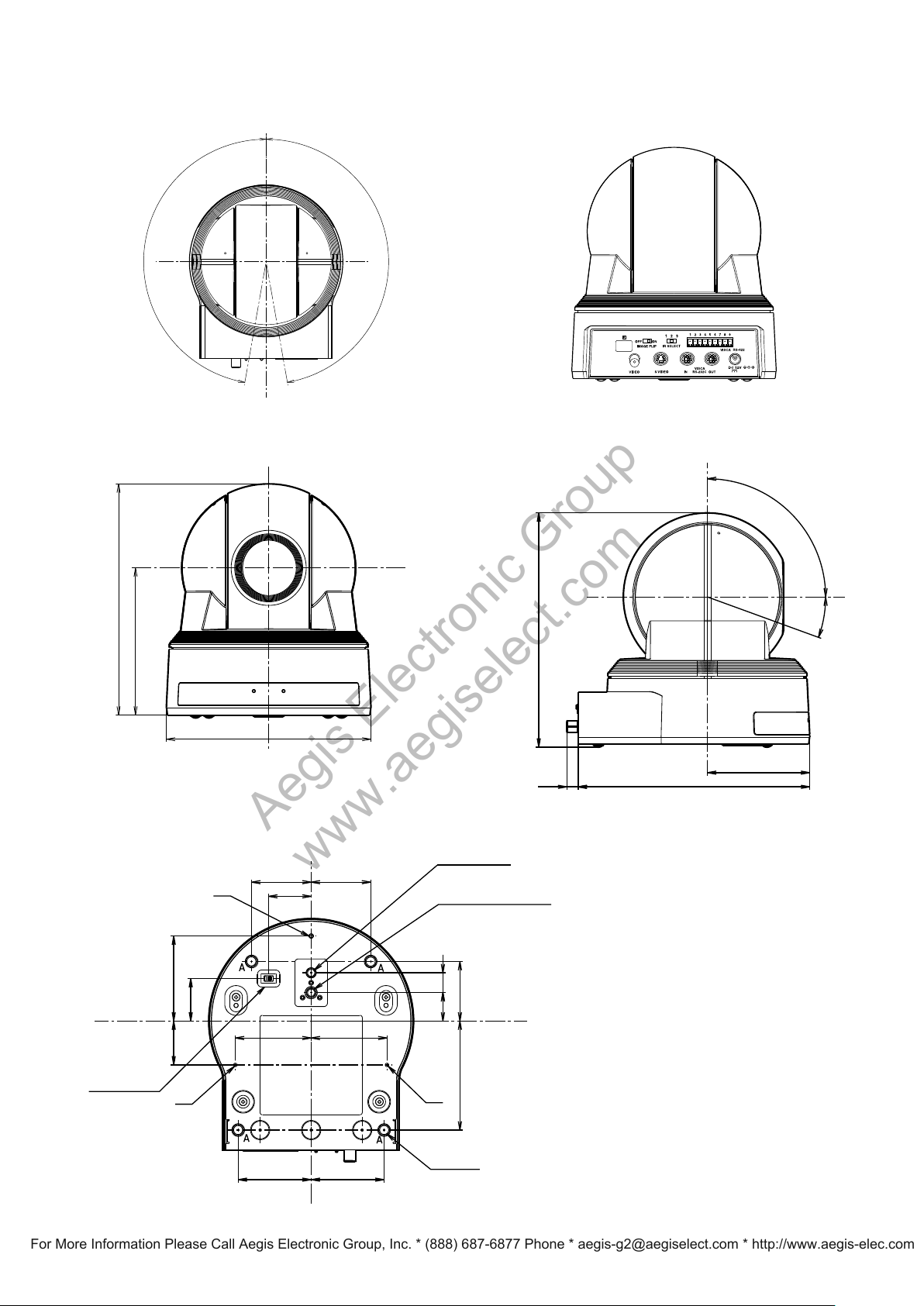
Dimensions
170°
170°
104(4 3/32)
164(6 15/32)
Ø145(5 1/32)
14( 9/16) 20( 25/32)
51.5(2 1/32) 51.5(2 1/32)
77(3 1/32)
42(1 43/64)
42(1 21/32)
42(1 21/32)
60(2 3/8)
31
(1 15/64)
30(1 3/16)
30(1 3/16)
53.5 53.5
(2 7/64) (2 7/64)
M3
M3
M3
(Leg)
4-Ø9(A)
Ø5, depth 5
1/4-20UNC, depth 6.5
Tripod screw hole
BOTTOM
switch
166(6 35/64)
164(6 15/32)
72(2 27/32)
8.5(11/32)
20°
90°
Aegis Electronic Group
www.aegiselect.com
For More Information Please Call Aegis Electronic Group, Inc. * (888) 687-6877 Phone * [email protected] * http://www.aegis-elec.com
Top Back
Front Side
Specifications
Bottom
Unit: mm (inches)
49
Page 50
Precautions
Aegis Electronic Group
www.aegiselect.com
For More Information Please Call Aegis Electronic Group, Inc. * (888) 687-6877 Phone * [email protected] * http://www.aegis-elec.com
Software
Use of the demonstration software developed by Sony
Corporation or use of the software with customer
developed application software may damage hardware,
the application program or the camera. Sony
Corporation is not liable for any damages under these
conditions.
Operation
Start the camera control software on your computer
after you turn on the camera and the image is
displayed.
Operation and storage locations
Do not shoot images that are extremely bright (e.g.,
light sources, the sun, etc.) for long periods of time. Do
not use or store the camera in the following extreme
conditions:
Extremely
0 ˚C to 40
Close to
radiation such as radio or TV transmitters
Where it
Where it
lighting conditions
Where it
hot or cold places (operating temperature
˚C (32 ˚F to 104 ˚F))
generators of powerful electromagnetic
is subject to fluorescent light reflections
is subject to unstable (flickering, etc.)
is subject to strong vibration
Other
Do not apply excessive voltage. (Use only the specified
voltage.) Otherwise, you may get an electric shock or a
fire may occur.
In case of abnormal operation, contact your authorized
Sony dealer or the store where you purchased the
product.
Care of the unit
Remove dust or dirt on the surface of the lens with a
blower (commercially available).
50
 Loading...