

Page 1

3-856-663-02 (1)
Color Video Camera
Operating Instructions
EN
EVI-D30
EVI-D31
(For European model only)
Page 2
Owner’s Record
The model number and the serial number are
located on the bottom exterior.
Record these numbers in the spaces provided
below. Refer to these numbers whenever you call
upon the dealer regarding this product.
Model No.
Serial No.
WARNING
To prevent fire or shock hazard, do not
expose the unit to rain or moisture.
WARNING
Mains cord must only be changed at qualified
service shop.
Appratet er forsynet med en speciel netledning,
der kun ma udskiftes af et autoriseret
serviceværksted.
For customers in the U.S.A.
This equipment has been tested and found to
comply with the limits for a Class B digital device,
pursuant to Part 15 of the FCC Rules. These limits
are designed to provide reasonable protection
against harmful interference in a residential
installation. This equipment generates, uses, and
can radiate radio frequency energy and, if not
installed and used in accordance with the
instructions, may cause harmful interference to
radio communications. However, there is no
guarantee that interference will not occur in a
particular installation. If this equipment does cause
harmful interference to radio or television
reception, which can be determined by turning the
equipment off and on, the user is encouraged to try
to correct the interference by one or more of the
following measures:
— Reorient or relocate the receiving antenna.
— Increase the separation between the equipment
and receiver.
— Connect the equipment into an outlet on a circuit
different from that to which the receiver is
connected.
— Consult the dealer or an experienced radio/TV
technician for help.
This symbol is intended to alert the
user to the presence of uninsulated
“dangerous voltage” within the
product’s enclosure that may be of
sufficient magnitude to constitute a
risk of electric shock to persons.
This symbol is intended to alert the
user to the presence of important
operating and maintenance (servicing)
instructions in the literature
accompanying the appliance.
* The graphical symbols are on the bottom enclosure.
For the customers in Canada
This Class B digital apparatus meets all
requirements of the Canadian Interference-Causing
Equipment Regulations.
CAUTION:
TO PREVENT ELECTRIC SHOCK, MATCH
WIDE BLADE OF PLUG TO WIDE SLOT,
FULLY INSERT.
Pour les utilisateurs au Canada
Cet appareil numérique de la classe B respecte
toutes les exigences du Règlement sur le matériel
brouilleur du Canada.
ATTENTION:
POUR ÉVITER LES CHOCS
ÉLECTRIQUES, INTRODUIRE LA LAME
LA PLUS LARGE DE LA FICHE DANS LA
BORNE CORRESPONDANTE DE LA
PRISE ET POUSSER JUSQU’AU FOND.
2
You are cautioned that any changes or
modifications not expressly approved in this
manual could void your authority to operate this
equipment.
EN
Page 3
For the customers in Netherlands
Voor de klanten in Nederland
Bij dit produkt zijn
batterijen geleverd.
Wanneer deze leeg zijn,
moet u ze niet weggooien
maar inleveren als KCA.
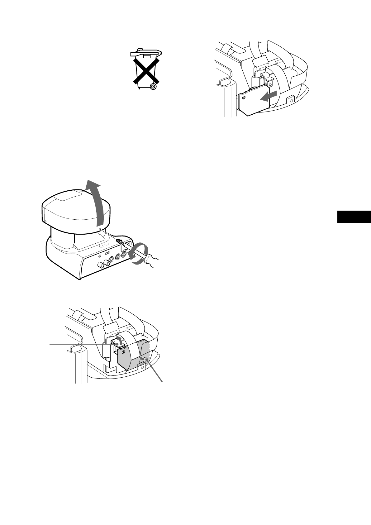
Als de kleuren-videocamera niet meer
werkt
Voor u de kleuren-videocamera wegdoet, dient u de
lithiumbatterij eruit te verwijderen om deze in te
leveren als KCA.
1 Draai de schroef aan de achterzijde van de
camerakop los met een kruiskopschroevedraaier en open de kap.
w
3 Verwijder het plaatje met de lithiumbatterij.
Zorg dat de lithiumbatterij niet in het afval
terechtkomt, maar lever deze in als KCA.
2 Maak de klem en de aansluiting los.
Klem
EN
q
Aansluiting
3
EN
Page 4

Features
• The CCD features effective picture elements of
380,000 (EVI-D30)/440,000 (EVI-D31), which
enables you high-resolution shooting.
• In addition to high-speed pan/tilt action, AT
(Automatic target tracking) and MD (Motion
detector) features are integrated, which lets you
use Color Video Camera for a variety of
purposes.
• VISCA lets you operate Color Video Camera
with a personal computer.
• Up to six combinations of the camera's position
and status can be memorized.
• Multi-function remote commander provided.
4
EN
Page 5

Table of Contents
Preparations
Connections ...........................................6
If you have a personal computer or
audio/video equipment with the
S-video input .............................................7
Turning on the Power ............................8
Setting the Clock .................................... 8
Basic Operations
Pan/Tilt Operation ................................10
Adjusting the Camera .......................... 11
Having the Camera Memorize the
Setting ................................................ 12
Advanced Operations
Tracking a Subject Automatically.......14
Fine-tuning the setting................................ 16
If a subject cannot be recognized or
captured ...................................................17
Detecting the Change Taking Place in
the Picture .......................................... 18
Fine-tuning the setting................................ 20
General
Locations of Controls .......................... 22
Precautions...........................................25
Maintenance .........................................26
Troubleshooting ................................... 26
Specifications ....................................... 27
5
EN
Page 6
Preparations
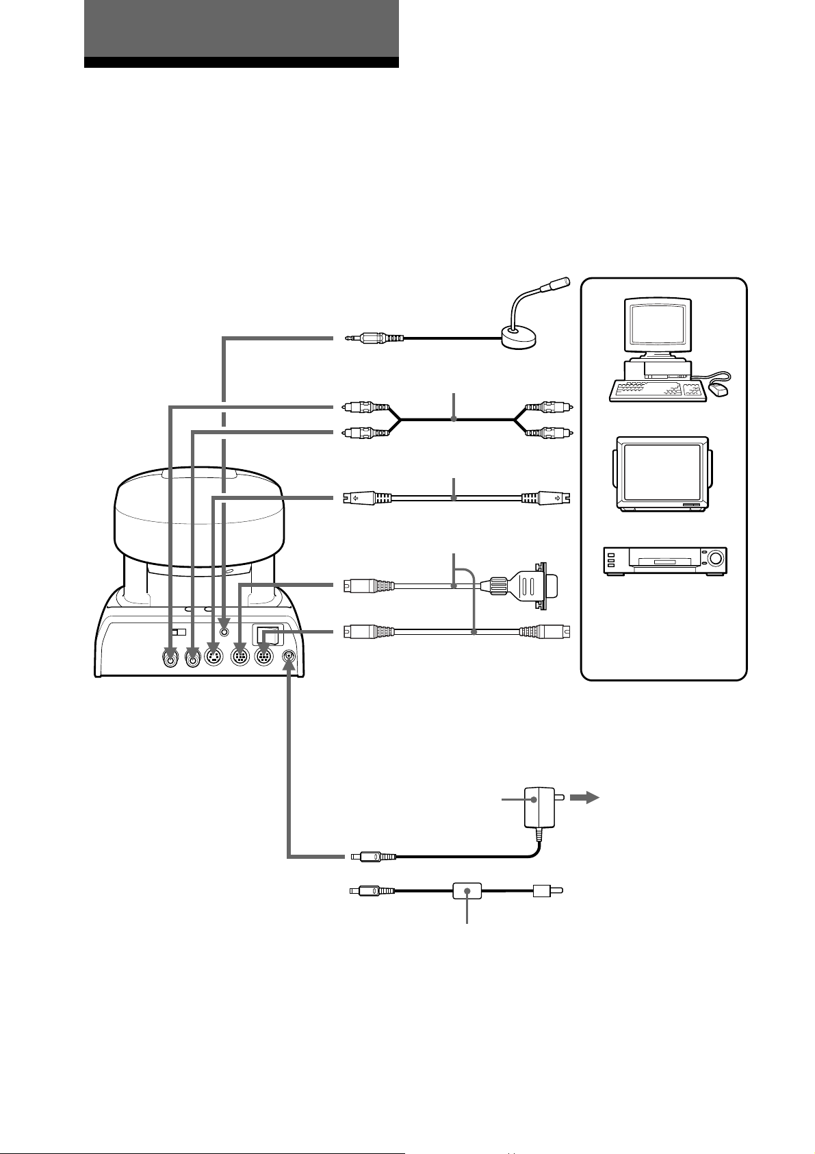
Connections
Connect your Color Video Camera to a personal
computer, TV or VCR equipped with an audio/
video input. Some connections may require extra
cables. Refer to the instructions manual of the
equipment to be connected.
to MIC
Microphone
(not supplied)
to AUDIO
OUT (black)
to VIDEO
OUT (yellow)
to S VIDEO OUT
VISCA cable (not supplied)*
to VISCA IN
to VISCA OUT To VISCA IN of other
Audio/Video
cable (supplied)
S-Video cable
(not supplied)
EVI-D30
(in case of connecting
to more cameras)
to Audio
input (black)
to Video input
(yellow)
to S-Video input
to RS-232C
Personal computer, TV
or VCR with an audio/
video input jack
6
EN
AC power adaptor AC-EV2
(supplied with EVI-D30)
to DC IN 13.5V
AC power adaptor AC-EV3
(supplied with EVI-D31)
* When the video camera is connected to a personal computer with a VISCA cable, you can operate the video camera
with the personal computer.
to AC outlet
Page 7
If you have a personal
computer or audio/video
equipment with the
S-Video input
You can connect it to your Color Video Camera
with a commercially available S-video cable.
Notes
• You cannot connect your Color Video Camera to a
personal computer that is not equipped with either audio/
video input or S-Video input jack. And you might not be
able to use your existing personal computer with your
Color Video Camera unless you provide the computer
with a video capture board, sound board, and/or
software. Consult your computer dealer or manufacturer
for details.
• Use only the AC-EV2 (for EVI-D30)/AC-EV3 (for EVID31) AC power adaptor (supplied). Do not use any other
AC power adaptor.
Polarity of the plug
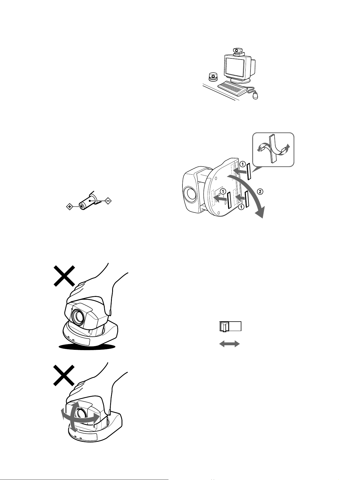
Installation
Be sure to place the main unit on a flat surface.
Secure the camera in place with the supplied Velcro
tape.
• Do not grasp the camera head when carrying the video
camera.
• Do not turn the camera head manually. Doing so will
result in the camera malfunctioning.
If you operate more than one camera
with the remote commander
Notice the CAMERA NO. switch at the rear of the
main unit. Set the CAMERA NO. switch to the
position that is different from the positions to that
of what the other cameras' CAMERA NO. switches
are set.
(See page 11.)
CAMERA NO.
1 2 3
7
EN
Page 8
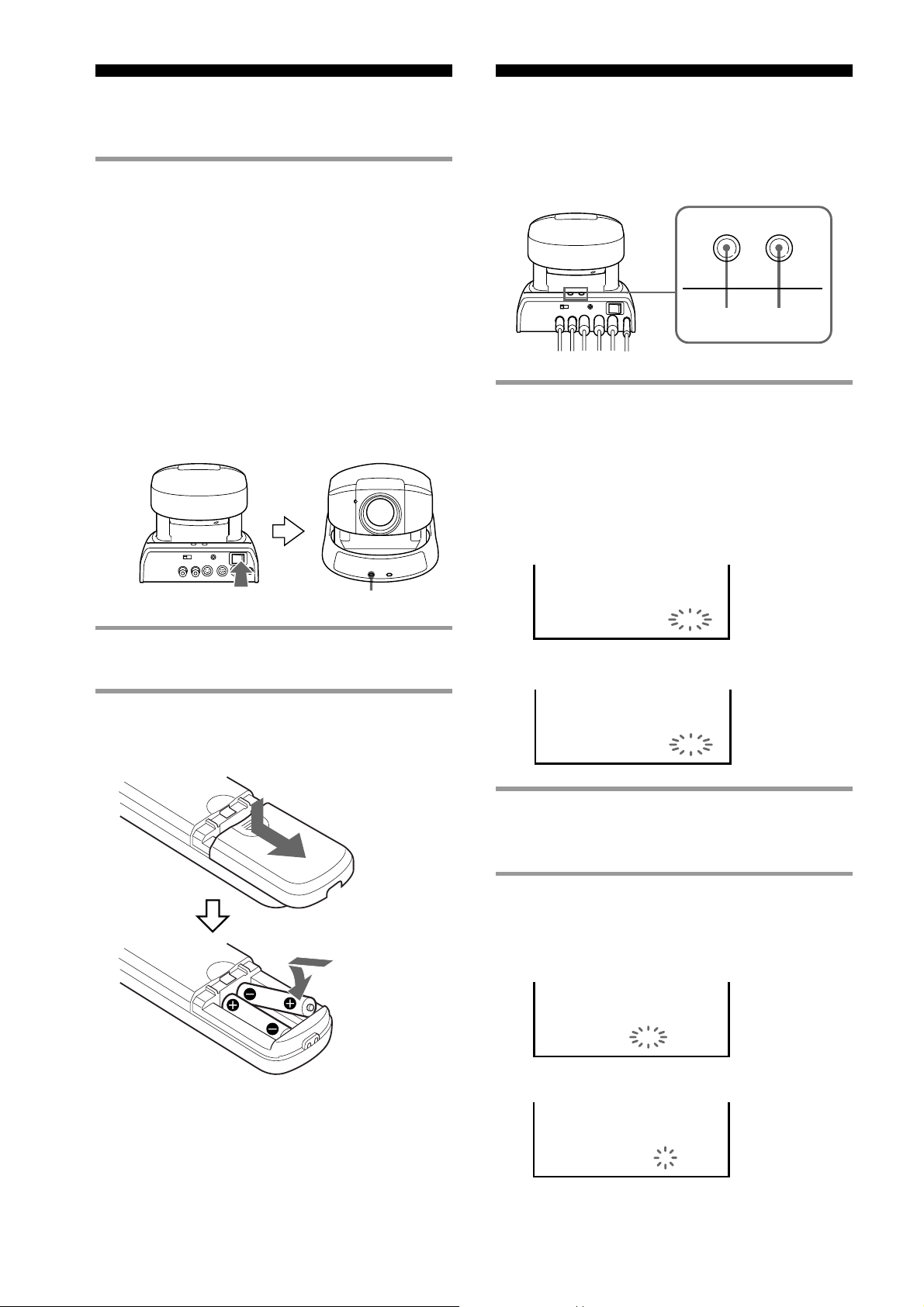
Turning on the Power Setting the Clock
Use the buttons on the main unit to set the clock.
1 Turn on the POWER switch at the rear of
the main unit.
The POWER lamp lights up.
As long as the POWER switch on the main
unit is set to ON, you can turn on or off the
camera with the POWER switch on the
remote commander.
When the power is turned on, the camera will
automatically face toward the lower righthand side and then the front, which is the
home position of the camera. (Pan/tilt reset
action)
1 Press the DATE and TIME buttons at the
same time and hold them down for about
2 seconds. Release your hand as the
month and date appear and the year starts
flashing.
EVI-D30
TIMEDATE
TIMEDATE
Light up.
2 Turn on the peripheral devices.
Installing batteries
R6 (size AA) x 2
(not supplied)
1996
JAN
1
EVI-D31
1996
1
1
2 Repeat pressing the DATE button to
select the year.
3 Press the TIME button to set the year.
EVI-D30
1996
JAN
1
8
EN
EVI-D31
1996
1
1
Page 9

4 Repeat the steps 2 and 3 to set the other
time elements in the order of month,
date, hour, and minute.
The clock starts operating as you press the
TIME button to set the minute.
EVI-D30
JUL
19964
3:15:01 PM
EVI-D31
199674
15:15:01
Having the clock displayed
You can select the clock display from either time or
date.
To have the time displayed, press the TIME
button.
To have the date displayed, press the DATE
button.
To turn off the clock display, press the
corresponding button again.
Note
When the POWER switch on the main unit is set to OFF,
the clock will be as originally was. To retain the memory
of the clock setting even if the power is turned off, set the
BACKUP switch, at the rear of the camera head, to ON.
(See “About backup” on page 25.)
9
EN
Page 10

Basic Operations
Pan/Tilt Operation
1
POWER
3
2
CAMERA SELECT
1
ON/OFFFAR ENTRYOFFSET
AT
CHASE
NEAR
MANUAL
AUTO ZOOM
AE
ON/OFF
MD
DATA SCREEN
STD REV
BACK LIGHT
STD
FOCUS
AUTO
HOME
L/R DIRECTION
SET
START/STOP FRAME DISPLAY
CAMERA SELECT
DETECTFRAME
123
456
PRESET
MENU
RESET
POSITION
PAN-TILT/CURSOR
HOME
CURSOR
REV
PAN-TILT
RESET
FAST
ZOOM·
SLOW·
TT
L/R
DIRECTION SET
2
PAN-TILT
RESET
WW
If you wish to face the camera toward
the opposite direction in which the
arrow on a pressed button points
The camera is preset to face toward the right
whenever the arrow ( ) button is pressed. You
might wish to face the camera toward the opposite
direction in which the arrow on a pressed button
points, in such a case when you change the
direction of the camera while checking the picture
on the screen. In this case, press the REV button
while holding down the L/R DIRECTION SET
button.
To reset that setting, press the STD button while
holding down the L/R DIRECTION SET button.
Arrow
button
the camera
SettingMovement of
While holding
down
L/R
DIRECTION SET
1 Press the POWER button.
The camera will be turned on, performing the
pan/tilt reset action automatically.
2 Press the arrow button to perform the
pan/tilt operation.
While checking the picture on the screen,
press a desired arrow button.
To move the camera inch by inch, press
the button for a moment.
To move the camera in a wide range,
press and hold down the button.
To move the camera diagonally, press
the arrow button ( or ) while holding
down the arrow button ( or ).
To face the camera back to the front
Press the HOME button.
If you accidentally move the camera
with your hand
Press the PAN-TILT RESET button to reset the
pan/tilt position.
The deviation from the position that the camera
memorizes will be corrected and the operation will
be back in order.
Press
STD
1
While holding
down
L/R
DIRECTION SET
Press
REV
2
Note
Repeat the above-mentioned procedure for each remote
commander if you are using more than one remote
commander. This is because the setting is performed by
changing the signal emitted from each remote commander,
not by changing the setting of the camera itself.
If the lamp at the side of the lens
flashes red
The micro computer inside the camera might not
memorize the current pan/tilt position properly.
Press the PAN-TILT RESET button to reset the
pan/tilt position.
Flashes.
10
EN
Page 11

Operating range of the remote
commander
Use the remote commander within the range
described below, facing it toward the receptor for
the remote commander.
Adjusting the Camera
BACK LIGHT
Receptor for remote
commander
7m
30°
60°
60°
30°
Operating more than one camera with
the remote commander
Notice the CAMERA NO. switch at the rear of the
camera to be operated.
Press a CAMERA SELECT button whose number
is the same as the number to which the CAMERA
NO. switch is set.
A pressed CAMERA SELECT button lights up
when either of the other button is pressed.
POWER
3
2
CAMERA SELECT
1
ON/OFFFAR ENTRYOFFSET
AT
CHASE
NEAR
MANUAL
AUTO ZOOM
AE
ON/OFF
MD
START/STOP FRAME DISPLAY
DATA SCREEN
STD REV
DETECTFRAME
RESET
123
456
POSITION
PRESET
PAN-TILT/CURSOR
MENU
CURSOR
HOME
SLOW·
PAN-TILT
RESET
FAST
ZOOM·
TT
WW
L/R
DIRECTION SET
ZOOM
AUTO
FAR
NEAR
MANUAL
BACK LIGHT
FOCUS
AUTO
Focusing on a subject
To focus the camera on a subject
automatically
Press the AUTO button.
The camera focuses on the subject at the center of
the screen automatically.
To focus the camera on a subject
manually
After pressing the MANUAL button, press either
FAR or NEAR button to have the camera focus on
the subject.
Focusing on a far subject
Focusing on a near subject
FOCUS
AUTO
ON/OFFFAR ENTRYOFFSET
CHASE
NEAR
MANUAL
ON/OFF
DATA SCREEN
CAEMRA SELECT
1
2 3
AT
AUTO ZOOM
AE
MD
DETECTFRAME
START/STOP FRAME DISPLAY
STD REV
Zooming
Press either of the four ZOOM buttons.
Subject
appears
farther away.
(Wide angle)
Zooms in or
out of subject
slowly.
(SLOW side)
SLOW·
TT
WW
L/R
DIRECTION SET
ZOOM·
FAST
Subject
appears
closer.
(Telephoto)
Zooms in or
out of
subject fast.
(FAST side)
Shooting with back lighting
When you shoot a subject with a light source
behind it, the subject becomes dark. In such a case,
press the BACK LIGHT button.
To cancel the function, press the BACK
LIGHT button again.
11
EN
Page 12

Having the Camera Memorize the Setting
1 Press the PAN-TILT RESET button to
reset the pan/tilt position.
—Presetting feature
Up to six combinations of the setting (position,
zooming, focusing and back lighting) can be preset.
POWER
3
2
3
PRESET
BACK LIGHT
FOCUS
AUTO
2
CAMERA SELECT
1
ON/OFFFAR ENTRYOFFSET
AT
CHASE
NEAR
MANUAL
DATA SCREEN
2
AUTO ZOOM
AE
ON/OFF
MD
START/STOP FRAME DISPLAY
123
STD REV
DETECTFRAME
456
POSITION
PRESET
MENU
RESET
PAN-TILT/CURSOR
HOME
CURSOR
3
POSITION
(1 – 6)
PAN-TILT
RESET
FAST
ZOOM·
SLOW·
TT
WW
L/R
DIRECTION SET
RESET
1
2 Adjust the position, zooming, focusing,
and back lighting of the camera. (See on
page 11.)
3 While holding down the PRESET
button, press either of the POSITION
buttons 1 – 6.
Press the
POSITION
button on
which the
settings are
to be preset.
While
holding
down
STD REV
123
456
PRESET
POSITION
MENU
PAN-TILT/CURSOR
RESET
12
EN
Page 13

Recalling the memorized setting
Press either of the POSITION buttons 1 – 6.
Canceling the preset memory
While holding down the RESET button, press the
POSITION button on which the settings are to be
canceled.
Press the
While
STD REV
123
456
PRESET
POSITION
MENU
PAN-TILT/CURSOR
RESET
POSITION
button on
which the
settings are
to be canceled.
holding
down
Notes
• Before presetting, be sure to reset the pan/tilt position.
Otherwise the correct position will not be memorized.
• The memorized information is retained until the power
of the main unit is turned off. To retain the memory even
if the power is turned off, set the BACKUP switch, at the
rear of the camera head, to ON. (See “About backup” on
page 25.)
13
EN
Page 14

Advanced Operations
Tracking a Subject Automatically
—AT (Auto target tracking) function
You can have the camera memorize certain color
and brightness so that it automatically tracks a
subject having the memorized color and brightness.
1
AT ON/OFF
3
AUTO ZOOM
AE
ON/OFF
MD
START/STOP FRAME DISPLAY
123
STD REV
AE
AUTO ZOOM
DETECTERAME
FRAME DISPLAY
RESET
456
POSITION
PRESET
PAN-TILT/CURSOR
HOME
MENU
CURSOR
3
START/STOP
PAN-TILT
RESET
FAST
ZOOM·
SLOW·
TT
WW
L/R
DIRECTION SET
2
POWER
CAMRA SELECT
BACK LIGHT
1
ON/OFFFAR ENTRYOFFSET
FOCUS
AUTO
NEAR
4
CHASE
DATA SCREEN
AT
CHASE
MANUAL
2
DETA SCREEN
Example of the case when a subject is
hardly recognized
The camera
might not
AT MODE P-T DRIVE
SETTING
ENTRY1
17
recognize a
subject if the
portion different
from the subject
in brightness and
color, such as
the backdrop, is
placed together
in the frame.
3 Press the START/STOP button to
activate the AT function.
Try moving the subject to see if the frame
tracks it automatically.
AT MODE
WORKING NOW
CHASE 1
14
1 Press the AT ON/OFF button to enter
into the AT setting mode.
The frame and setting value appear.
AT MODE P
SETTING
CHASE 1
-
T DRIVE
ENTRY1
32
Frame
2 Press the arrow button to perform the
pan/tilt operation so that a subject is
placed into the frame.
EN
Be sure to
place the
subject so
that the
portion
uniform in
brightness
and color
is in the
frame.
AT MODE P
SETTING
CHASE 1
-
T DRIVE
ENTRY1
51
The larger
the value
is, the
more
easily the
camera
recognizes
the
subject.
When the frame tracks the subject,
proceed with the step 4.
When the frame does not track the
subject, repeat the step 3 until the frame
starts tracking the subject while adjusting the
lighting and the position of the subject so that
the color and brightness of the subject is
optimized. If the frame still does not track the
subject, see “If the subject cannot be
recognized or captured” on page 17.
4 Repeat pressing the CHASE button to
select a desired CHASE mode.
Each time that button is pressed, the mode is
cyclically changed as follows:
CHASE 1 CHASE 2 CHASE 3
AT MODE
WORKING NOW
CHASE 2
Page 15

MODE
CHASE 1
Tracking method
The pan/tilt action is
not performed.
(Camera does not
move.) The frame
tracks a subject only in
the range of the screen.
Intended use
Used to check
if the subject is
recognized.
To keep the brightness of the subject
as is (Auto back lighting function)
After the step 2, press the AE button.
AT MODE P
SETTING
-
T DRIVE
ENTRY1
51
CHASE 2
CHASE 3
* The position in which the subject is to be placed can be
changed from the middle of the screen. See “Changing
the frame position” on page 16.
The frame tracks a
subject while the pan/
tilt action is performed.
In this mode, the
subject is always
placed in the middle of
the screen.*
Uses the same tracking
method as that of
CHASE 1 except that if
a subject almost goes
out of the screen, the
camera performs the
pan/tilt action so that
the subject is placed in
the middle of the
screen.*
Used to
perform
normal
tracking
operation.
Used when
you wish to
limit the
camera
movement as
possible, in
such a case
when you
perform the
image
transmission.
If the frame is repeatedly extended to
the full screen
The camera does not recognize the subject. Press
the START/STOP button and go back to the step 2.
If doing so does not solve the problem, see “If a
subject cannot be recognized or captured” on page
17.
To turn off the setting value and/or
frame
If the setting value and/or frame are displayed as
you record a picture, those come with the recorded
picture.
To turn off the setting value, press the DATA
SCREEN button.
To turn off the frame, press the FRAME
DISPLAY button.
AT AE
CHASE 1
To disactivate the function, press that button
again.
Note
Be sure to press the AE button before proceeding with the
step 3. This function is not activated after the START/
STOP button is pressed.
To keep the size of the memorized
subject as is
After the step 2, press the AUTO ZOOM button.
To cancel the function, press that button again.
To cancel the AT function
Press the START/STOP button.
The information of the memorized subject is
erased.
To exit from the AT setting mode, press the
AT ON/OFF button.
If the lamp at the side of the lens light
up
The camera is not capturing the memorized subject
correctly.
Press the arrow button to perform the pan/tilt
operation so that the subject comes into the screen.
Or have the subject memorized onto the camera
again.
Lights up.
Note
Once the setting value is turned off, the setting value is not
displayed until the next time you press the DATA
SCREEN button. However, the setting value is displayed
automatically when the unit enters into the AT setting
mode for the first time after the power is turned back on.
continue to next page
15
EN
Page 16

Tracking a Subject Automatically
(continued)
Fine-tuning the setting
Changing the frame position
Although the frame normally appears on the middle
of the screen, you can change its position to a
different place. (In the CHASE 1 mode, the frame
tracks a subject within the range of the screen.)
POWER
3
2
CAMRA SELECT
1
ON/OFFFAR ENTRYOFFSET
AT
CHASE
NEAR
MANUAL
AUTO ZOOM
AE
ON/OFF
MD
START/STOP FRAME DISPLAY
DETA SCREEN
STD REV
DETECTERAME
RESET
123
456
POSITION
PRESET
PAN-TILT/CURSOR
MENU
2,4
HOME
CURSOR
PAN-TILT
RESET
FAST
ZOOM·
SLOW·
TT
L/R
DIRECTION SET
3
WW
1
BACK LIGHT
FOCUS
AUTO
3 Press the arrow button to move the frame
to a desired position.
AT MODE FRAME DRIVE
SETTING
CHASE 1
ENTRY1
30
4 Press the OFF SET button to fix the
frame position.
-
AT MODE P
SETTING
CHASE 1
After the setting is completed, go back to the
step 2 of “Tracking a subject automatically.”
T DRIVE
ENTRY1
30
1 Press the AT ON/OFF button to enter
into the AT setting mode.
The frame and setting value appear. If the
setting value does not appear, press the DATA
SCREEN button to have the value displayed.
AT MODE P
SETTING
CHASE 1
-
T DRIVE
ENTRY1
32
Frame
2 Press the OFF SET button to enter into
the AT frame position setting mode.
AT MODE FRAME DRIVE
SETTING
ENTRY1
32
16
CHASE 1
EN
Page 17

If a subject cannot be
recognized or captured
Depending on the characteristic or condition of a
subject, the camera might hardly recognize the
subject. If the AT function still does not work after
the procedures mentioned in pages 14 and 15 are
repeated, select an ENTRY mode that is matched to
conditions under which the camera is used.
Normally, select the ENTRY 1.
Problem
ENTRY
mode to
be selected
1 Press the AT ON/OFF button to enter
into the AT setting mode.
The frame and setting value appear. If the
setting value does not appear, press the DATA
SCREEN button to have the value displayed.
AT MODE P
SETTING
CHASE 1
-
T DRIVE
ENTRY1
32
Frame
A subject cannot be recognized
because its color is too thin.
The camera repeats mistakenly
recognizing a near object whose
color is almost identical to that of a
subject. (The frame moves from the
subject to an object whose color is
almost identical to that of the
subject.)
The camera repeats mistakenly
recognizing the backdrop such as
the wall or ceiling. (The frame
moves from the subject to the
backdrop.)
The camera does not capture a
subject correctly when the
brightness of the subject changes as
the position of the subject changes.
POWER
3
1
BACK LIGHT
FOCUS
AUTO
2
CAMRA SELECT
1
ON/OFFFAR ENTRYOFFSET
AT
CHASE
NEAR
MANUAL
AUTO ZOOM
AE
ON/OFF
MD
START/STOP FRAME DISPLAY
DETA SCREEN
STD REV
2
DETECTERAME
RESET
123
456
POSITION
PRESET
PAN-TILT/CURSOR
MENU
CURSOR
HOME
SLOW·
ZOOM·
TT
4
PAN-TILT
RESET
FAST
WW
L/R
DIRECTION SET
ENTRY 2
ENTRY 2
ENTRY 4
ENTRY 3
3
2 Repeat pressing the ENTRY button to
select a desired ENTRY mode.
Each time that button is pressed, the mode is
cyclically changed as follows:
ENTRY 1 ENTRY 2 ENTRY 3
ENTRY 4
AT MODE P
SETTING
CHASE 1
-
T DRIVE
ENTRY4
52
3 Have the camera memorize a subject by
pressing the arrow button to move the
subject into the frame.
The position to which you place the subject
varies depending on an ENTRY mode you
select.
ENTRY 2: Place the subject so that the
portion uniform to a certain extent in color
and brightness is in the frame.
ENTRY 3: Place the subject so that it hangs
over the frame slightly.
ENTRY 4: Place the subject so that it
becomes largest within the frame, its
backdrop being out of the frame.
continue to next page
17
EN
Page 18

Tracking a Subject Automatically
(continued)
Detecting the
4 Press the START/STOP button to
activate the AT function.
Try moving the subject to see if the frame
tracks it automatically.
If you have selected the ENTRY 3, the frame
flashes for about 5 seconds after the START/STOP
button is pressed. Within that period, repeat
changing the angle of the subject so that the camera
recognizes the various brightness of the subject.
Notes
• If you use the ENTRY 2 or 4 mode for a subject that can
be recognized even in the ENTRY 1 mode, the subject
might be hardly recognized. This is because the color
and brightness the camera can recognize are limited in
the ENTRY 2 and 4 modes.
• Even if you try changing the ENTRY mode, a subject
still might not be recognized depending on its
characteristics. In such a case, try changing the subject
to the one whose color is more bright or the one whose
color is different from that of its backdrop, or changing
the lighting.
• There might be a case in which the AT function will not
activated in any way depending on the size, color,
brightness and so on of a subject.
Change Taking Place
in the Picture
— MD (Motion Detector) function
If the position of the camera is fixed, you can set the
camera to detect a change taking place in a picture.
When the camera detects a change taking place in
the picture, the frame appears, showing the portion
in which the change takes place, and the lamp at the
side of the lens lights up red. (At that time, the
detection signal is output from the VISCA IN.)
You can specify up to two portions in which the
change is detected, by using the two frames
(FRAME 1 and FRAME 2) that you can change in
position and size as desired.
1
MD ON/OFF
POWER
CAMRA SELECT
BACK LIGHT
1
ON/OFFFAR ENTRYOFFSET
FOCUS
AUTO
NEAR
DATA SCREEN
6
START/STOP
2
AT
CHASE
MANUAL
3
AE
ON/OFF
MD
DETA SCREEN
AUTO ZOOM
DETECTERAME
START/STOP FRAME DISPLAY
123
STD REV
456
PRESET
MENU
2,3,4
5
FRAME DISPLAY
RESET
POSITION
PAN-TILT/CURSOR
HOME
ZOOM·
SLOW·
CURSOR
TT
PAN-TILT
RESET
FAST
WW
L/R
DIRECTION SET
3,4
18
EN
1 Press the MD ON/OFF button to enter
into the MD setting mode.
The frame and setting value appear.
-
MD MODE P
SELECT FRAME
FRAME 1
T DRIVE
Page 19

2 Press the FRAME button to enter into the
detection frame setting mode.
5 Repeat pressing the DETECT button to
select a frame to be used.
MD MODE FRAME DRIVE
SET FRAME
FRAME 1
3 Decide the position and size of the
FRAME 1.
q Press the arrow button to set the position
of the FRAME 1. Then press the FRAME
button.
MD MODE FRAME DRIVE
SET FRAME
FRAME 1
Each time that button is pressed, the frame to
be used is cyclically changed as follows:
FRAME 1 FRAME 2 F1 & F2*
MD MODE FRAME DRIVE
SET FRAME
F1&F2
* If a change is detected even in either of FRAME 1
or FRAME 2, the lamp at the side of the lens lights
up red.
6 Press the START/STOP button to
activate the MD function.
MD MODE
WORKING NOW
w Press the arrow button to set the size of the
FRAME 1. Then press the FRAME
button.
MD MODE FRAME DRIVE
SET FRAME
FRAME 1
That completes the settings of the FRAME 1’s
position and size, and enter into the setting
mode of the FRAME 2.
If you choose not to set the FRAME 2,
proceed with the step 5.
4 Repeat the procedure of the step 3 to set
the FRAME 2’s position and size.
FRAME 1
To turn off the setting value and/or
frame
If the setting value and/or frame are displayed as
you record a picture, those come with the recorded
picture.
To turn off the setting value, press the DATA
SCREEN button.
To turn off the frame, press the FRAME
DISPLAY button.
To cancel the MD function
Press the START/STOP button.
To exit from the MD mode, press the MD ON/
OFF button.
Note
Once the frame is set, it remains memorized until the
power is turned off.
To retain the memory of the frame setting even if the power
is turned off, set the BACKUP switch, at the rear of the
camera head, to ON. (See “About backup” on page 25.)
continue to next page
19
EN
Page 20

Detecting the Change Taking Place in
the Picture (continued)
Fine-tuning the settings
The MD function works in the following manner:
the camera memorizes a picture of a certain
moment as the “reference picture,” and compares
the current picture with the reference picture to
detect whether or not a change takes place.
Although the camera is factory-set to refresh a
reference picture after a certain period of time, you
can change the timing when a reference picture is
refreshed or can set the camera not to refresh the
reference picture, according to conditions under
which the camera is used.
In addition, you can adjust the parameter that sets
the camera to detect a certain kind of change such
as color and brightness.
POWER
1
3,6
BACK LIGHT
FOCUS
AUTO
MENU
2
CAMRA SELECT
1
ON/OFFFAR ENTRYOFFSET
AT
CHASE
NEAR
MANUAL
DETA SCREEN
4,5
3
AE
ON/OFF
MD
AUTO ZOOM
DETECTERAME
START/STOP FRAME DISPLAY
123
STD REV
456
PRESET
MENU
2
START/STOP
RESET
POSITION
PAN-TILT/CURSOR
CURSOR
HOME
SLOW·
PAN-TILT
RESET
FAST
ZOOM·
TT
WW
L/R
DIRECTION SET
5
4,5
1 Press the MD ON/OFF button to enter
into the MD setting mode.
Condition under
which the
camera is used
Sunlight comes
in, and the light
source changes
over time.
• Sunlight comes
in, and the
quantity of light
changes over
time.
• You wish to
have the
camera detect
only a sudden
change.
•
Sunlight does not
come in, and the
brightness of the
light source does
not change.
•
You wish to have
the camera detect
even a slight
change.
Reference
picture
refreshing
mode to
be
selected
MODE 1
MODE 2
MODE 3
When to refresh
The reference picture
is automatically
refreshed after a
certain period of time
(Factory-setting :
approx. 0.1 second)
The reference picture
is automatically
refreshed after a
certain period of
time unless a change
has taken place in
the picture. When a
change is being
detected, the
reference picture is
not refreshed.
The reference
picture is always
as originally was.
The frame and setting value appear. If the
setting value does not appear, press the DATA
SCREEN button to have the setting value
displayed.
-
MD MODE P
SELECT FRAME
FRAME 1
T DRIVE
2 Press the START/STOP button to start
the detection operation.
3 Press the MENU button to enter into the
MD ADJUST MODE.
MD ADJUST MODE
MODE
BRIGHT
HUE
SIZE
REFRESH
DISPLAY
15
1
2
0
1
3
4 While holding down the CURSOR
button, press the arrow button (
or ) to select a desired reference
picture refreshing mode (1 – 3).
20
EN
Page 21

5 Adjust each parameter.
q While holding down the CURSOR button,
press the arrow button ( or ) to
select a desired parameter.
w While holding down the CURSOR button,
press the arrow button ( or
) to select a desired value.
Adjust the value of each parameter as
specified below, in the order from top to
bottom.
MODE 1 MODE 2 MODE 3
BRIGHT 2 2 2
HUE 15 15 15
SIZE 0 0 0
REFRESH 1 8 –*
DISPLAY 3 0 0
*When the MODE 3 is selected, you cannot change
the value of REFRESH since the reference picture
is not refreshed in that mode.
6 Press the MENU button to complete the
setting.
If the detection operation is not performed
properly, see “Adjusting the value of each
parameter.”
Adjusting the value of each
parameter
At the step 5 of “Fine-tuning the setting,” you can
adjust the value of each parameter as desired.
Refer to the following information provided below
and adjust the value of each parameter while
checking how the detection operation is performed.
Parameter
BRIGHT*
(Sensitivity
to
brightness)
HUE*
(Sensitivity
to hue)
SIZE*
(Sensitivity
to size)
REFRESH*
(Reference
picture
refreshing
timing)
DISPLAY
(Signal
output
duration)
1
2
3
Content/Tips in setting
Sets the sensitivity to a
change in brightness. The
lesser the value, the more
sensitively the camera
detects the change. Adjust
this value within the range
in which an error does not
occur.
Sets the sensitivity to a
change in color. The lesser
the value, the more subtle
change in color the camera
detects. Adjust this value
when the camera hardly
detects the change with
only the BRIGHT adjusted,
in such a case when the
brightness of a subject to be
captured is almost
identical to that of its
backdrop.
Sets the sensitivity to the
size of the frame area
being taken up by a
changed portion. Adjust
this value in such a case
when you wish to have
the camera detect only a
greater change.
4
Sets the period of time for
which the reference
picture is retained.
Sets the period of time for
which the detection signal
continues to be generated
once a change has been
detected.
Adjustable
range
0 to14,
15
(Parameter
disabled)
0 (5°) to
14 (75°),
15
(Parameter
disabled)
0 (approx.
0.3%) to
15 (approx.
20%)
0 (0.07 sec.)
to 15
(60 min.)
0 (0.07 sec.)
to 14 (30
min.), 15
(continuous)
*1 After the value of the BRIGHT has been changed, the
value of the HUE is automatically set to 15 and the
value of the SIZE to 0.
*2 After the value of the HUE has been changed, the value
of the BRIGHT is automatically set to 15 and the value
of the SIZE to 0.
*3 Be sure to adjust the value of the SIZE after adjusting
the values of the BRIGHT and HUE.
• The camera might not be able to detect a change if
both the size of the frame and the value of the SIZE
are too small.
*4 Can be adjusted only when the camera is in the MODE
1 or MODE 2.
21
EN
Page 22

General
Locations of Controls
For details, see the pages indicated in .
Main unit
1
2
4
5
3
7
8
9
10
11
1 Caution lamp
2 POWER lamp 8
3 RECEIVE lamp
4 Lens
5 Receptor for remote commander
6 IR OUT switch
Use when equipment such as a VTR and
personal computer, and/or another Color Video
Camera are connected with a VISCA cable.
7 TIME button
8 CAMERA NO. switch 7
10 15
11
8
11
9 VIDEO OUT jack 6
10
AUDIO OUT jack 6
11
S VIDEO OUT jack 6
12
DATE button 8
13
BACK UP switch
14
MIC jack 6
15
POWER switch 8
16
DC IN 13.5V jack 6
17
VISCA OUT jack 6
18
VISCA IN jack 6
6
12
13
14
15
16
17
18
25
22
EN
Page 23

Remote commander
1
2
BACK LIGHT
3
FOCUS
AUTO
POWER
2
CAMERA SELECT
1
ON/OFFFAR ENTRYOFFSET
AT
CHASE
ON/OFF
NEAR
MANUAL
DATA SCREEN
4
7
3
AUTO ZOOM
AE
DETECTFRAME
MD
START/STOP FRAME DISPLAY
123
STD REV
5
8
9
RESET
456
POSITION
PRESET
PAN-TILT/CURSOR
MENU
HOME
CURSOR
6
10
PAN-TILT
ZOOM·
SLOW·
TT
11
RESET
FAST
WW
L/R
DIRECTION SET
12
13
14
1 BACK LIGHT button
2 FOCUS buttons
11
11
AUTO button
FAR button
NEAR button
MANUAL button
3 DATA SCREEN button
START/STOP button 14
FRAME DISPLAY button
4 MENU button
5 CURSOR button
20
21
15
19
15
6 L/R DIRECTION SET button
7 POWER switch
10
8 CAMERA SELECT buttons
9 AT mode buttons
AT ON/OFF button
OFF SET button
ENTRY button
CHASE button
AE button
15
AUTO ZOOM button
14
16
17
14
15
11
10
10
MD mode buttons
MD ON/OFF button
FRAME button
DETECT button
11
POSITION buttons
18
19
19
12
Numeric buttons (Button 1 also works as the
STD button./Button 2 also works as the REV
button.)
10
PRESET button
RESET button
12
PAN-TILT/CURSOR button 10 14 16
Arrow buttons
HOME button
13
PAN-TILT RESET button
14
ZOOM buttons
11
10
SLOW T button
SLOW W button
FAST T button
FAST W button
19
continue to next page
23
EN
Page 24

Locations of Controls (continued)
Screen indications
AT setting mode 14 –
AT mode indication
Status indication
(SETTING ←→ WORKING
NOW)
Auto back lighting
indication
CHASE indication (1 to 3)
MD setting mode 18
MD mode indication
17
19
AT MODE P
SETTING
AT AE
CHASE 1
MD MODE P
SELECT FRAME
-
T DRIVE
ENTRY1
32
-
T DRIVE
Camera/frame operation
indication (P-T DRIVE ←→
FRAME DRIVE)
ENTRY indication (1 to 4)
Color temperature
indication
Frame
Frame selecting/setting
indication (SELECT
FRAME ←→ SET FRAME)
Selected frame indication
FRAME 1 FRAME 2 F1 & 2
(
MD adjusting mode
Parameter setting
mode indication
(MD ADJUST MODE)
20
FRAME 1
)
MD ADJUST MODE
MODE
BRIGHT
HUE
SIZE
REFRESH
DISPLAY
1
2
15
0
1
3
24
EN
Page 25

Precautions
2 Remove the stopper and connector.
• The name plate indication operating voltage,
power consumption, etc. is located on the bottom
exterior.
• After operating the unit with an AC power
adaptor, disconnect the AC power adaptpr from
the wall outlet if the set is not to be used for an
extended period of time. The POWER switch on
the rear of the main unit, does not turn the AC
adaptor off.
Brightness of a subject
Color Video Camera might not work with its best
performance in a place where brightness exceeds
the illumination range (such as a place exposed to
direct sunlight).
Avoid specialized
application
Avoid using Color Video Camera for monitoring
application where it would be forced to focus on a
stationary object for a long period of time. Also
avoid focusing the camera on an extremely bright
object such as sunlight or a fluorescent lamp.
Otherwise the color filter might be damaged.
Precaution on copyright
Television programs, pictures, magazines, and
other materials may be copyrighted. Unauthorized
recording or storing of such materials violates the
provision of the copyright laws.
Stopper
Connector
3 Remove the lithium battery together with the
board.
Dispose of the lithium battery according to the local
law.
About backup
The memories of the settings such as the clock,
camera's position and MD function are erased when
the POWER switch on the main unit is set to OFF.
To retain those memories, set the BACK UP
switch, at the rear of the camera head, to ON.
When you discard Color
Video Camera
For environmental reasons, take out a lithium
battery from the camera and discard it accordingly.
1 Remove the screw at the rear of the camera head
using a Phillips type screw driver and detach the
cabinet.
w
q
BACKUP
ONOFF
Notes
• In this unit, the built-in lithium battery acts as the power
source for retaining the memories and is kept charged as
long as the unit is used. If the unit is used for shorter
period of time with the BACKUP switch set to ON,
however, the battery is gradually discharged. Besides, if
you do not use the unit at all for almost 12 weeks, the
battery is completely discharged. To retain the
memories of the settings, you should recharge the
battery.
• To recharge the battery, plug in the unit to an AC outlet
with the AC power adaptor and leave it for
approximately 48 hours with the POWER switch on the
main unit set to ON.
25
EN
Page 26

Symptom
Remedy
Maintenance
Clean dirt and soil with a soft cloth or tissue paper.
Cleaning the main unit
• When the body is too dirty, clean it with a soft
cloth that is soaked with a diluted neutral
detergent and tightly wrung. Then finish with a
dry cloth.
• Do not use any type of solvents, which may
damage the finish.
• When you use a chemical cloth, follow its
instructions.
• Do not sprinkle volatile matter such as pesticide
over Color Video Camera nor allow rubber or
vinyl to come in contact with Color Video
Camera for a long period of time. Doing so may
damage the finish.
Replacing the batteries of
the remote commander
If the remote commander does not operate from a
longer distance, the batteries may be worn out.
Replace the batteries with new ones (AA × 2).
Troubleshooting
The unit cannot be
operated when a
button on the remote
commander is
pressed.
The unit cannot be
operated when either
of the POSITION
buttons (1 to 6) is
pressed.
The unit cannot be
operated when an
arrow button, the
HOME button, or
the PAN-TILT
RESET button is
pressed.
The unit cannot be
operated when an
arrow button is
pressed.
• Set the POWER switch, at
the rear of the main unit, to
ON.
• Press a CAMERA SELECT
button whose number is the
same as the number to which
the CAMERA No. switch of
the camera is set.
• Replace the batteries of the
remote commander with new
ones.
• Plug in the AC power adaptor
to an AC outlet.
Check which mode the camera
is in.
If the camera is in the AT
mode, press the AT ON/OFF
button to exit from that mode.
If the camera is in the MD mode,
press the MD ON/OFF button to
exit from that mode.
Press the MD ON/OFF button
to exit from the MD mode.
Check which mode the camera
is in.
If the camera is in the AT frame
position setting mode, press the
AT ON/OFF button to exit from
that mode.
If the camera is in the detection
frame setting mode, press the
MD ON/OFF button to exit from
that mode.
26
Symptom
The picture does not
appear on the screen
of the AV personal
computer.
The picture and
sound qualities are
not as good as those
of TV when you
connect Color Video
Camera to AV
personal computer.
EN
Remedy
• Make sure the connections are
made correctly.
• Have Color Video Camera
tested by connecting it to
other equipment such as a
TV or video deck.
Depending on a computer or
video capture board, you may
not be able to obtain the same
picture and sound qualities as
those of TV. Consult your
computer manufacturer or
dealer for details.
The unit cannot be
operated by any
means.
Turn off and then back on
after a while the POWER
switch at the rear of the main
unit.
If you still cannot operate the
unit, set the BACK UP switch
to OFF and turn off and then
back on the POWER switch.
(Note that the memories of
each setting will be erased
when the BACK UP switch is
set to OFF.)
Page 27

Specifications
System
Video signal EVI-D30: NTSC Color, EIAJ
standards
EVI-D31: PAL Color, CCIR
standards
1
Picture element
Lens Electromotion twelve fold zoom lens
Point-blank range
Minimum illumination
Illumination range
Shutter speed EVI-D30:
Gain selector Automatic/manual
Horizontal resolution
Video S/N 48 dB
Pan/tilt action Horizontal: 100°, Vertical: 25°
/3 inch color CCD
(Total picture element number:
EVI-D30: Approx. 410,000
EVI-D31: Approx. 470,000)
(Effective picture element number:
EVI-D30: Approx. 380,000
EVI-D31: Approx. 440,000)
f=5.4 to 64.8mm, F1.8 to F2.7
Horizontal angle: 4.4° to 48.8°
WIDE end : 10mm
TELE end : 800mm
7 lux (F1.8)/with 50IRE
7 to 100,000 lux
control)
EVI-D31:
control)
NTSC : 460 TV
PAL : 450 TV
1
/60 to 1/10,000 (VISCA
1
/50 to 1/10,000 (VISCA
General
Input voltage DC 12 to 14 V
Power consumption
11 W
Operating temperature
0° to 40° (32° to 104°F)
Storage temperature
– 20° to 60° (– 4° to 140°F)
Dimensions Video camera: Approx 142 × 109 ×
164 mm (5
(w/h/d)
Remote commander: Approx.
56 × 26 × 210 mm (2
3
/8 in.) (w/h/d)
8
Mass Video camera: Approx. 1,200 g
(42.3 oz.)
Remote commander: Approx.
109 g (3.8 oz)
5
/8 × 4 3/8 × 6 1/2 in.)
1
/4 × 1 1/16 ×
Supplied accessories
AC power adaptor (1)
Audio/video cable (1)
Remote commander (1)
Velcro tape (3 sets)
Input/output terminals
Video output RCA pin jack (1), 1Vpp, 75 ohm
unbalanced
Synchronization: negative
S video output 4 pin mini DIN (1)
Audio output RCA pin jack, monaural (1)
Rated output: 327 mV
Output impedance: less than
2.2 kilohms
Input/output control terminals
RS232C (input: 1, output: 1), 8 pin
mini DIN, 9600bps
Data: 8 bit
Stop bit: 1
Microphone input terminal
Mini jack (monaural) (1) (ø 3.5)
Rated input 0.775 mV
DC 3V for low impedance
microphone
Input impedance: more than 10
kilohms
Power terminal EIAJ type4
27
EN
 Loading...