

Page 1
ES-7
3-856-429-13(1)
TM
EditStation
Operating Instructions
Before operating the unit, please read this manual
thoroughly and retain it for future reference.
ES-7
1996 by Sony Corporation
Page 2
Owner’s Record
The model and serial numbers are located at the rear.
Record the serial number in the space provided below.
Refer to these numbers whenever you call upon your Sony
dealer regarding this product.
Model No. ES-7 Serial No.
WARNING
To prevent fire or shock hazard, do not expose
the unit to rain or moisture.
For the customers in the USA
This equipment has been tested and found to comply with the
limits for a Class A digital device, pursuant to Part 15 of the
FCC Rules. These limits are designed to provide reasonable
protection against harmful interference when the equipment
is operated in a commercial environment. This equipment
generates, uses, and can radiate radio frequency energy
and, if not installed and used in accordance with the
instruction manual, may cause harmful interference to radio
communications. Operation of this equipment in a residential
area is likely to cause harmful interference in which case the
user will be required to correct the interference at his own
expense.
You are cautioned that any changes or modifications not
expressly approved in this manual could void your authority
to operate this equipment.
The shielded interface cable recommended in this manual
must be used with this equipment in order to comply with the
limits for a digital device pursuant to Subpart B of Part 15 of
FCC Rules.
Voor de klanten in Nederland
• Deze set bevat een lithiumbatterij voor de memory back-up.
• De batterij voor memory back-up is vastgesoldeerd bij U23
op de printplaat.
• Raadpleeg uw leverancier over de verwijdering van de
batterij op het moment dat u de set bij einde levensduur
afdankt.
• Gooi de batterij niet weg, maar lever hem in als KCA.
• Bij dit produkt zijn batterijen geleverd. Wanneer deze leeg
zijn, moet u ze niet weggooien maar inleveren als KCA.
NOTICE TO USERS
© 1996 Sony Corporation. All rights reserved. This manual
or the software described herein, in whole or in part, may not
be reproduced, translated or reduced to any machine
readable form without prior written approval from Sony
Corporation.
SONY CORPORATION PROVIDES NO WARRANTY WITH
REGARD TO THIS MANUAL, THE SOFTWARE OR OTHER
INFORMATION CONTAINED HEREIN AND HEREBY
EXPRESSLY DISCLAIMS ANY IMPLIED WARRANTIES OF
MERCHANTABILITY OR FITNESS FOR ANY PARTICULAR
PURPOSE WITH REGARD TO THIS MANUAL, THE
SOFTWARE OR SUCH OTHER INFORMATION. IN NO
EVENT SHALL SONY CORPORATION BE LIABLE FOR
ANY INCIDENTAL, CONSEQUENTIAL OR SPECIAL
DAMAGES, WHETHER BASED ON TORT, CONTRACT, OR
OTHERWISE, ARISING OUT OF OR IN CONNECTION
WITH THIS MANUAL, THE SOFTWARE OR OTHER
INFORMATION CONTAINED HEREIN OR THE USE
THEREOF.
CAUTION
The use of optical instruments with this product will increase
eye hazard.
For the customers in Europe
This EditStation is classified as a
CLASS 1 LASER PRODUCT.
The CLASS 1 LASER
PRODUCT label is located on
the rear panel of the EditStation.
2
Sony Corporation reserves the right to make any modification
to this manual or the information contained herein at any time
without notice.
The software described herein may also be governed by the
terms of a separate user license agreement.
Page 3

Table of Contents
Chapter 1
Overview
Chapter 2
Introduction to
Editing Operations
Features .............................................................................7
Contents of the Package ...................................................... 8
System Configuration.......................................................9
Analog Hybrid Editing System ........................................... 9
Digital Hybrid Editing System .......................................... 10
Digital Non-Linear Editing System................................... 11
Analog Linear Editing System .......................................... 12
Analog Linear Editing System With External Switcher.... 13
Optional Components and Software............................. 14
Optional System Upgrade Devices.................................... 14
Optional Expansion Boards............................................... 14
Optional Software Products .............................................. 15
Related Manuals................................................................ 15
Starting and Shutting Down the System ...................... 17
Starting the System............................................................ 17
Using the Mouse................................................................ 20
Using the Keyboard........................................................... 22
Using Windo ws ................................................................. 24
Shutting Down the System ................................................ 26
The Basics of Editing With EditStation ......................... 28
Reference Editing System ................................................. 28
The Flow of an Editing Session ........................................ 29
Starting EditStation ........................................................... 30
Identifying Parts of the EditStation Initial Screen............. 32
Preparing a Master Tape .................................................... 33
Creating Video Clips ......................................................... 34
Copying Video Clips to the Disk Recoder ........................ 38
Editing With Cut Transitions............................................. 39
Previewing the Edit Results............................................... 40
Adjusting Edit Points ........................................................ 42
Adding Wipe Effects ......................................................... 44
Adding Fade-in and Fade-out Effects................................ 47
(Continued)
Table of Contents 3
Page 4

Table of Contents
Chapter 2
Introduction to
Editing Operations
(Continued)
Chapter 3
Connections and
Settings
Table of Contents
Inserting a Title.................................................................. 51
Recording the Edit Results................................................ 57
Saving the Edit File ........................................................... 58
Using the Online Manual .................................................. 59
Exiting EditStation ............................................................ 62
Arranging System Components ....................................63
Using Floppy Disks.........................................................64
Using CD-ROM Discs......................................................66
Connecting System Components ................................. 67
Connecting VCRs.............................................................. 67
Connecting ESBK-7045 Disk Units.................................. 71
Connecting Computer Peripherals .................................... 72
Connecting Video/Audio Monitors and
Audio Equipment ......................................................... 73
Connecting an External DME Switcher ............................ 74
Installing Optional Boards .............................................76
Installing Expansion Boards on the Motherboard............. 77
Installing Daughter Boards................................................ 81
Installing Expansion Boards in ISA Slots ......................... 85
Recommended Connectable Video Equipment............86
Setting the Video Signal Format .................................... 87
Setting Up Windows NT (Using the Unit for the First
Time) ............................................................................88
Setting the Date and Time ..............................................89
Reinstalling the Software ...............................................90
Registering User Names and Passwords .....................91
Executing the Self Diagnostics......................................93
Pin Assignments .............................................................94
GPI Pin Assignments......................................................... 94
Computer Connector Section Pin Assigments ................. 94
4 Table of Contents
Page 5

Chapter 4
Location and
Function of Parts
Appendixes
Front Panel.......................................................................97
Rear Panel........................................................................98
Common Section ............................................................... 98
Connector Sections............................................................ 99
Error Messages .............................................................107
Precautions....................................................................108
Maintaining the Performance of This Unit...................... 108
Protecting Data on the Hard Disk ................................... 108
Handling CD-ROM Discs ............................................... 108
Handling Floppy Disks.................................................... 109
Specifications................................................................111
Glossary.........................................................................114
Index...............................................................................115
Table of Contents 5
Page 6

Page 7

Features
Chapter 1 Overview
The ES-7 EditStation™ is a video editing system that
includes as built-in equipment all of the devices
required for video editing. Powerful editing software
running under the pre-installed Microsoft Windows
1)
operating system provides a graphical user
NT
interface that allows you to perform linear editing of
video materials on tape and non-linear editing of
2)
materials on a disk recorder.
The combination of
easy-to-use editing software and expansion board
developed especially for the EditStation enables the
EditStation to function as an A/B roll editing system,
video switcher, digital multi-effects, audio mixer,
titler, and drawing platform. It supports a rich variety
of analog and digital video signal formats and features
a high-speed digital transfer function that enables you
to transfer video data between the disk recorder and
DSR-series VCRs at four times normal speed with no
loss in video quality.
High-quality video compression
Dynamic video compression provides efficient storage
of digital signals on the disk recorder. The
compression ratio is adjusted to accommodate the
amount of information in the data while preserving
high video quality.
Many advanced special effect functions
Optional special effects expansion boards with built-in
video switcher functions are available to provide more
than 300 high-quality special effects in real time.
Installation of an additional optional expansion board
provides advanced non-linear three-dimensional
effects such as lighting, which depicts the object as if
illuminated by a light source, and trail, which produces
a trail across the video image.
Convenient graphics tools
Optional drawing software and an expansion board for
drawing functions are available to provide
superimposed graphics on video signals. This allows
you to create graphics while checking the effect on the
monitor. Lettering is provided by standard EditStation
software (Text Composer) that can be used from the
editing screen. This allows you to create titles and
other lettering without the need to acquire a separate
character generator. A file converter is also provided
as a standard feature, allowing you to convert graphics
data created with Photoshop
applications for use with this unit.
3)
and other graphics
Chapter 1 Overview
High-speed uploads and downloads
High-quality audio signal processing
You can copy edit materials from DSR-series VCRs to
the EditStation disk recorder (upload) and copy edit
results from the EditStation disk recorder to DSRseries VCRs (download) at four times normal speed.
The EditStation and DSR-series VCRs share a
common internal format, eliminating the need for
compression and decompression during uploads and
downloads. This eliminates the deterioration in video
quality which can result from copy operations.
..........................................................................................................................................................................................................
1) Windows NT is a trademark of Microsoft Corporation.
2) The disk recorder is a combination of the ESBK-7041
Disk Recorder Board and one or more ESBK-7045 Disk
Units.
The system features a digital audio mixer as standard
equipment. If you install the optional digital input/
output board, you can perform input and output of
video and audio signals in completely digital formats.
High-quality recording of analog audio input signals is
also possible.
3) Photoshop is a registered trademark of Adobe Systems
Incorporated.
Chapter 1 Overview 7
Page 8

Features
Support for DSR-series VCRs
The EditStation can read and perform high-speed
editing of MARK IN edit point video and MARK IN
Chapter 1 Overview
and MARK OUT edit point timecode recorded with
DSR-series camcorders.
Easy operation
You can check the sequence of video clips in your
EDL (Edit Decision List) in a single glance at the
display on the computer monitor. Compared to
conventional character-based systems, the visual
display makes EDL operations easy and intuitive. You
can move or insert video clips through simple dragand-drop operations with the mouse, eliminating the
need to learn complicated commands.
Compatible with wide variety of analog
and digital systems
Contents of the Package
The ES-7 EditStation package contains the following.
•ES-7 main unit (1)
•Power cord (1)
•Keyboard (1)
•Mouse (1)
•Extension cable for keyboard/mouse, length 4 m (2)
•Parallel GPD D-sub 15-pin connector (1)
•Software and online manual (CD-ROM disc) (1)
•Windows NT package (CD-ROM disc and manuals)
(1)
•Operating Instructions (this manual) (1)
•Software License Agreement (1)
•User registration card (1)
You can mix both analog and digital equipment in the
same editing system, and combine linear and nonlinear editing. This makes it easy to begin with an
inexpensive analog editing system and upgrade it by
adding digital and non-linear components.
Control panel
An optional control panel is available, featuring a jog/
shuttle dial, a fader lever and other editing controls.
Use of the control panel makes it easy to control VCR
tape transport and perform fine adjustments of edit
points.
8 Chapter 1 Overview
Page 9
System Configuration
You can configure a variety of editing systems around
the ES-7 EditStation. The main types are as follows.
•Analog hybrid editing system
•Digital hybrid editing system
•Digital non-linear editing system
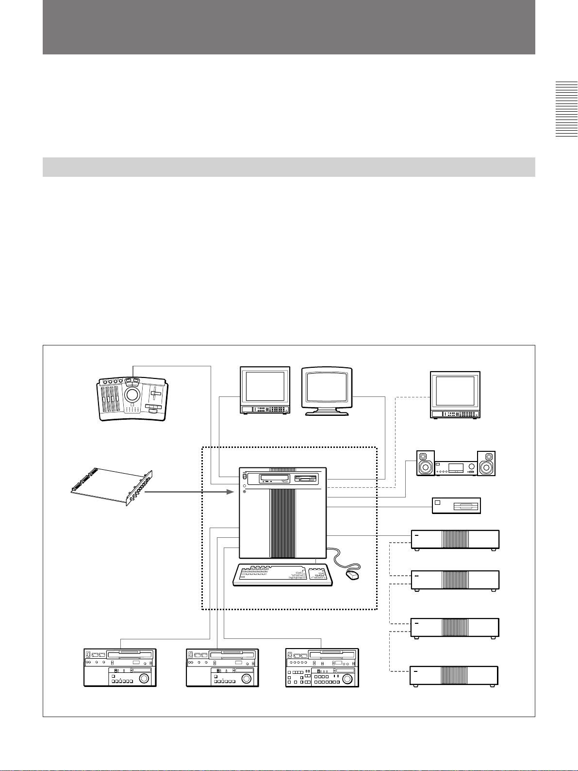
Analog Hybrid Editing System
As the video switcher, this system employs the
optional ESBK-7021 Basic DME Switcher Board or
ESBK-7023 Advanced DME Switcher Board. As the
three-dimensional effects processor, it employs the
optional ESBK-7022 3D Effect Board for Basic DME
Switcher or ESBK-7024 3D Effect Board for
Advanced DME Switcher.
The configuration includes two analog player VCRs
and one analog recorder VCR. This enables hybrid
editing, which is the application of special effects
while switching between video stored on the disk
recorder and video stored on tape.
•Analog linear editing system
The following sections show how each type of editing
system is configured.
Chapter 1 Overview
For editing with a large number of short cuts, video
clips can be copied from tape to the disk redorder. This
improves editing efficiency by taking advantage of the
rapid cue-up times for clips stored on disk. Longer cuts
can be recorded directly from tape, saving the time
required to copy clips to the disk recorder. Depending
on the materials and contents of the edit, you can
choose whichever method is most efficient.
The results of the edit are recorded on tape by the
recorder VCR. The MO drive is used to store and
access edit data.
ESBK-7011 Control Panel
• ESBK-7021 Basic DME Switcher
Board (or ESBK-7023 Advanced DME
Switcher Board)
• ESBK-7022 3D Effect Board for Basic
DME Switcher (or ESBK-7024 3D
Effect Board for Advanced DME
Switcher)
• ESBK-7041 Disk Recorder Board
• ESBK-7051 SCSI Option
Player VCR 1 Player VCR 2 Recorder VCR
ES-7 EditStation
Keyboard
All components not enclosed by
the broken lines are optional.
Computer monitorPreview monitor
Mouse
Program monitor
(connect as required)
Audio amplifier and speakers
MO drive
ESBK-7045 Disk Unit
ESBK-7045 Disk Unit
(connect as required)
ESBK-7045 Disk Unit
(connect as required)
ESBK-7045 Disk Unit
(connect as required)
Analog hybrid editing system
Chapter 1 Overview 9
Page 10
System Configuration
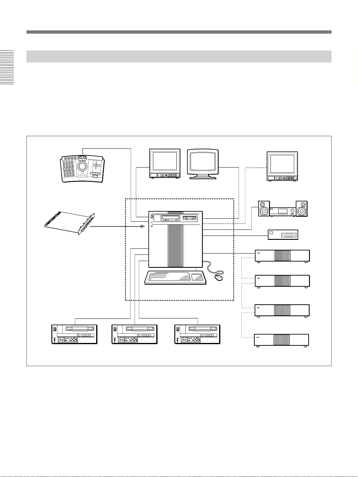
Digital Hybrid Editing System
As the video switcher, this system employs the
optional ESBK-7021 Basic DME Switcher Board or
Chapter 1 Overview
ESBK-7023 Advanced DME Switcher Board. As the
three-dimensional effects processor, it employs the
optional ESBK-7022 3D Effect Board for Basic DME
Switcher or ESBK-7024 3D Effect Board for
Advanced DME Switcher.
ESBK-7011 Control Panel
• ESBK-7021 Basic DME Switcher
Board (or ESBK-7023 Advanced DME
Switcher Board)
• ESBK-7022 3D Effect Board for Basic
DME Switcher (or ESBK-7024 3D
Effect Board for Advanced DME
Switcher)
• ESBK-7041 Disk Recorder Board
• ESBK-7031 QSDI Interface Board
• ESBK-7032 SDI Interface Board
• ESBK-7051 SCSI Option
The configuration includes DSR-series or digital
Betacam player and recorder VCRs. This enables
hybrid editing, which is the application of special
effects while switching between video stored on the
disk recorder and video stored on tape.
The results of the edit are recorded on tape as digital
data by a digital VCR. The MO drive is used to store
and access edit data.
Preview monitor Computer monitor
ES-7 EditStation
Keyboard
All components not enclosed by
the broken lines are optional.
Program monitor
(connect as required)
Audio amplifier and speakers
MO drive
ESBK-7045 Disk Unit
Mouse
ESBK-7045 Disk Unit
(connect as required)
DSR-85/85P or
DVW-500/500P
(Player 1)
10 Chapter 1 Overview
DSR-85/85P or
DVW-500/500P
(Player 2)
DSR-85/85P or
DVW-500/500P
(Recorder )
Digital hybrid editing system
ESBK-7045 Disk Unit
(connect as required)
ESBK-7045 Disk Unit
(connect as required)
Page 11
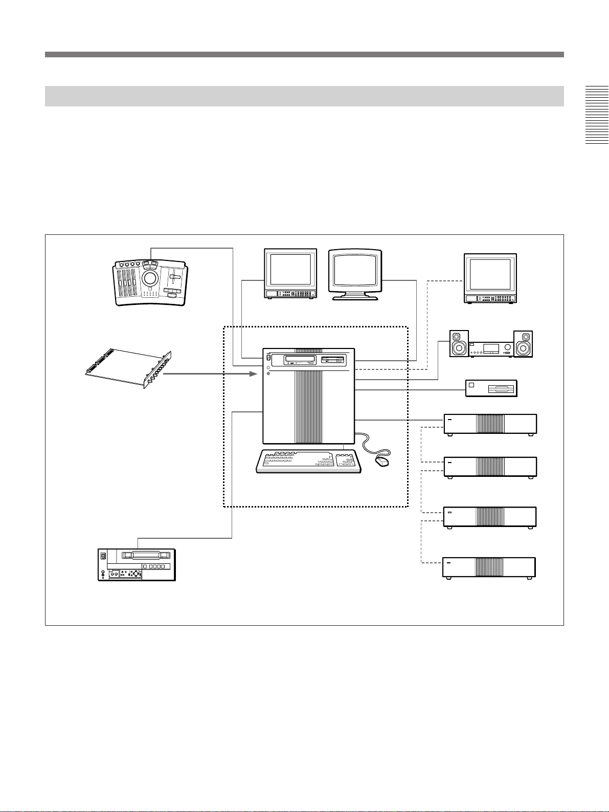
Digital Non-Linear Editing System
As the video switcher, this system employs the
optional ESBK-7021 Basic DME Switcher Board or
ESBK-7023 Advanced DME Switcher Board. As the
three-dimensional effects processor, it employs the
optional ESBK-7022 3D Effect Board for Basic DME
Switcher or ESBK-7024 3D Effect Board for
Advanced DME Switcher.
ESBK-7011 Control Panel
• ESBK-7021 Basic DME Switcher
Board (or ESBK-7023 Advanced
DME Switcher Board)
• ESBK-7022 3D Effect Board for
Basic DME Switcher (or ESBK7024 3D Effect Board for Advanced
DME Switcher)
• ESBK-7041 Disk Recorder Board
• ESBK-7031 QSDI Interface Board
• ESBK-7051 SCSI Option
Preview monitor Computer monitor
ES-7 EditStation
Keyboard
A DSR-series digital VCR is connected as the
recorder. Materials for editing are uploaded from the
digital VCR to the system’s hard disks at four times
normal speed. Editing is non-linear, employing data
stored on the disk recorder. The results of the edit are
downloaded to the digital VCR at four times normal
speed. The MO (magneto-optiocal disk) drive is used
to store and access edit data.
Program monitor
(connect as required)
Audio amplifier and speakers
MO drive
ESBK-7045 Disk Unit
Mouse
ESBK-7045 Disk Unit
(connect as required)
Chapter 1 Overview
DSR-85/85P (Recorder )
All components not enclosed by
the broken lines are optional.
ESBK-7045 Disk Unit
(connect as required)
ESBK-7045 Disk Unit
(connect as required)
Digital non-linear editing system
Chapter 1 Overview 11
Page 12
System Configuration
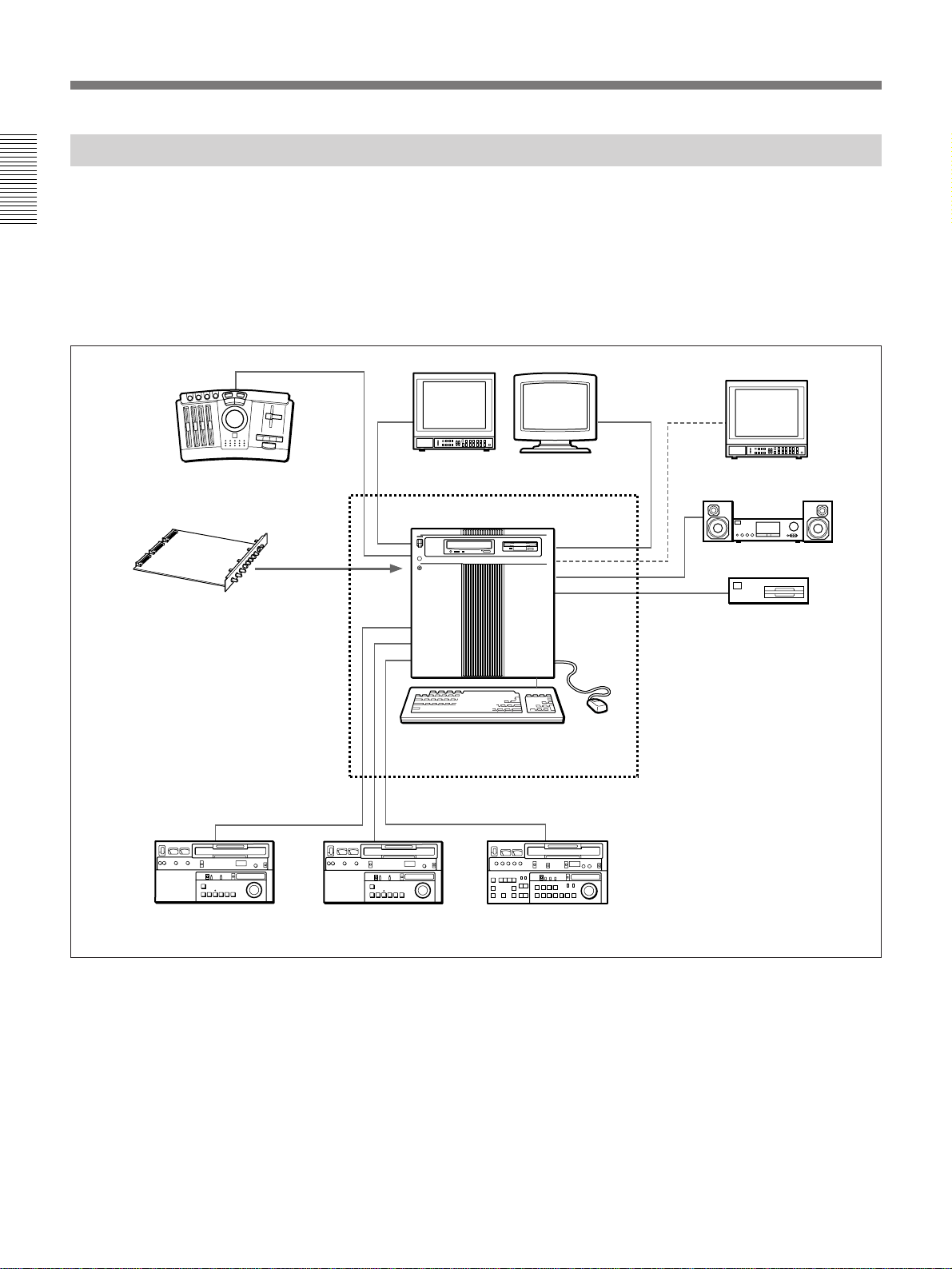
Analog Linear Editing System
As the video switcher, this system employs the
optional ESBK-7021 Basic DME Switcher Board or
Chapter 1 Overview
ESBK-7023 Advanced DME Switcher Board. As the
three-dimensional effects processor, it employs the
optional ESBK-7022 3D Effect Board for Basic DME
Switcher or ESBK-7024 3D Effect Board for
Advanced DME Switcher.
ESBK-7011 Control Panel
• ESBK-7021 Basic DME Switcher
Board (or ESBK-7023 Advanced
DME Switcher Board)
• ESBK-7022 3D Effect Board for
Basic DME Switcher (or ESBK-7024
3D Effect Board for Advanced DME
Switcher)
• ESBK-7051 SCSI Option
Two analog VCRs are connected as players, and one
analog VCR is connected as the recorder.
This system permits tape-based linear editing only.
The results of the edit are recorded on tape by the
recorder. The MO drive is used to store and access edit
data.
Preview monitor Computer monitor
ES-7 EditStation
Keyboard
Mouse
Program monitor
(connect as required)
Audio amplifier and speakers
MO drive
Player VCR 1 Player VCR 2 Recorder VCR
12 Chapter 1 Overview
All components not enclosed by
the broken lines are optional.
Analog linear editing system
Page 13
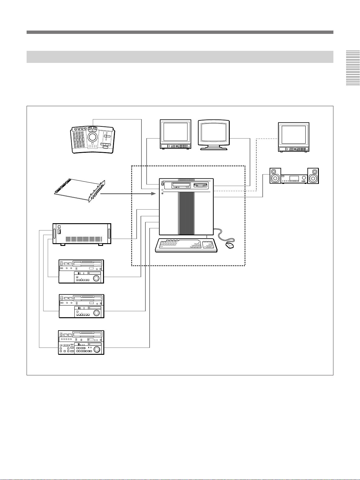
Analog Linear Editing System With External Switcher
If you already own a DFS-300/300P or DFS-500/500P
DME Switcher, you can combine the EditStation and
your current switcher.
This system employs a DFS-300/300P or DFS-500/
ESBK-7011 Control Panel
ES-7 EditStation
ESBK-7025 External Switcher
Interface Board
DFS-300/300P or DFS-500/500P
DME Switcher
Keyboard
500P DME Switcher as the video switcher and effects
processor. Two analog VCRs are connected as players,
and one analog VCR is connected as the recorder. This
system permits tape-based linear editing only.
Computer monitorPreview monitor
Mouse
Program monitor
(connect as required)
Audio amplifier and speakers
Chapter 1 Overview
Player VCR 1
Player VCR 2
Recorder VCR
All components not enclosed by
the broken lines are optional.
Analog linear editing system with external switcher
Chapter 1 Overview 13
Page 14

Optional Components and Software
Optional System Upgrade
Devices
Chapter 1 Overview
ESBK-7045 Disk Unit
This is a hard disk drive for storage of video and audio
signals. The fast random access of the hard disk means
that any part of the data can be accessed quickly.
Unlike clips stored on tape, clips stored on a disk unit
can be cued up instantly. In high-quality mode, one
disk unit can store up to one hour of video. Up to four
disk units can be connected to the EditStation.
ESBK-7041 Disk Recorder Board
This board installs in a slot on the motherboard of the
EditStation. It controls the ESBK-7045 Disk Unit and
enables non-linear editing using data on the disk unit.
ESBK-7011 Control Panel
ESBK-7023 Advanced DME Switcher
Board
This is a set of two expansion boards that install in
slots on the motherboard of the EditStation. The
boards provide video and audio switcher functions and
two-dimensional DME (Digital Multi-Effects)
functions. They also provide color correction, a
downstream keyer, and a chroma key function.
Compared to the Basic DME Switcher Board, these
boards provide even higher picture quality, enabling
the addition of a wide variety of advanced special
effects.
ESBK-7024 3D Effect Board for Advanced
DME Switcher
This is a daughter board that installs on the Advanced
DME Switcher Board. It provides linear and non-linear
three-dimensional special effects.
It also provides lighting and trails effects.
This is a control panel for the EditStation featuring a
jog/shuttle dial, a fader lever, adjustment knobs,
MARK IN and MARK OUT buttons, and other editing
controls. Use of the control panel makes it easy to
control tape transport, adjust edit points, and manually
specify the timing of edit transitions.
Optional Expansion Boards
ESBK-7021 Basic DME Switcher Board
This is a set of two expansion boards that install in
slots on the motherboard of the EditStation. The
boards provide video and audio switcher functions and
two-dimensional DME (Digital Multi-Effects)
functions. They also provide color correction, a
downstream keyer, and a chroma key function.
ESBK-7022 3D Effect Board for Basic DME
Switcher
ESBK-7025 External Switcher Interface
Board
This is an expansion board that installs in a slot on the
motherboard of the EditStation.
It enables control of DFS-500/500P or DFS-300/300P
DME Switcher from the EditStation while playing
back VCR tapes for linear editing.
ESBK-7031 QSDI Interface Board
This is an expansion board that installs in a slot on the
motherboard of the EditStation. It enables input and
output of QSDI video signals and AES/EBU digital
audio signals. Install this board when you wish to
connect equipment such as a DSR-series VCR, a CD
player, or a DAT (Digital Audio Tape) recorder and
player for input and output of digital audio signals.
This is a daughter board that installs on the Basic
DME Switcher Board. It provides linear and non-linear
three-dimensional special effects.
14 Chapter 1 Overview
Page 15

ESBK-7032 SDI Interface Board
This is a daughter board that installs on the ESBK7031 QSDI Interface Board. It provides input and
output of digital video signals in the component digital
format (D1 format). Install this board when you wish
to connect equipment such as a DSR-series digital
VCR or a DVW-series digital Betacam VCR. This
board is required to perform digital linear editing with
the EditStation and a DSR-series VCR.
ESBK-7051 SCSI Option
This is an expansion board that installs in an ISA slot
of the EditStation to enable connection of an external
MO drive (recommended connection cable: ESBK-
7053). The MO drive is used to exchange edit data,
including index pictures of video clips, with external
equipment.
ESBK-7052 Ethernet Option
Optional Software Products
ESBK-7071 ESDraw™
Chapter 1 Overview
This is a drawing program for the EditStation,
provided on CD-ROM (Compact Disc Read-Only
Memory). It is supplied with an adapter board which,
when installed in the EditStation, enables you to
perform drawing operations and view the results on a
video monitor while other processing is performed in
the background. An online manual explaining how to
use the software is provided together with the software
on the CD-ROM disc.
ESBK-7092E Operation Manual
This is a printed manual that provides detailed
information about how to use ESDraw.
The contents of this manual are also provided on the
ESBK-7071 ESDraw CD-ROM disc.
This is an expansion board that installs in an ISA slot
of the EditStation. It enables you to connect the
1)
EditStation to an Ethernet
network. Install this board
when you wish to use a network to exchange graphics
or index pictures and other edit data.
Additional Memory Set ESBK-7054
This is an expansion memory kit for the ES-7
EditStation. It is made up of two memory modules and
provides a memory capacity of 64 MBytes.
Related Manuals
The EditStation is supplied with a CD-ROM disc that
contains an online manual with detailed operating
instructions. The online manual is also available in a
printed version as the ESBK-7091E EditStation
Operation Manual.
The contents of the EditStation manuals are as follows.
•Operating Instructions (this manual)
This manual provides an overview of the system,
information about installation and connections, and
basic operating instructions. It also explains how to use
the online manual and provides information about
specifications and other supplementary topics.
After purchasing the unit, read this manual for
information about installation, connections, and basic
operating procedures.
•Online Manual (supplied on CD-ROM) and
Operation Manual (optional printed manual)
These manuals provide detailed instructions about how
to operate the EditStation. Refer to these manuals for
details of operation and installation which are not
covered in the Operating Instructions.
..........................................................................................................................................................................................................
1) Ethernet is a registered trademark of FUJI XEROX CO.,
LTD.
Chapter 1 Overview 15
Page 16

Page 17
Starting and Shutting Down the System
This chapter explains how to start and shut down the system, how to use
the mouse and keyboard, and how to perform window operations. The
operations described here are used by all editing functions.
Note
The software must be set up when you use the unit for the first time.
For more information about setting up the software, see “Setting Up Windows NT
(Using the Unit for the First Time)” (page 88).
Chapter 2 Introduction to Editing Operations
Starting the System
Chapter 2 Introduction to Editing Operations
When you power the system on, a screen appears asking you to enter your
user name and password. This is the logon screen, designed to prevent
unauthorized use by non-registered users.
In the factory default configuration, you can begin using the EditStation
immediately, simply pressing the Enter key without entering a user name
and password at the logon screen.
If you wish to limit use of the EditStation to specific users, you can
register their user names and passwords.
For details, see “Registering User Names and Passwords” (page 91).
To launch the system software, proceed as follows.
1 Power on the system hardware in the following order.
1) Computer monitor, MO drive, printer and other peripherals, and
VCRs, video monitor, audio amplifier or audio monitor system
2) EditStation main unit
Powering on (or off) the EditStation main unit causes the ESBK-7045
Disk Unit to be automatically powered on (or off).
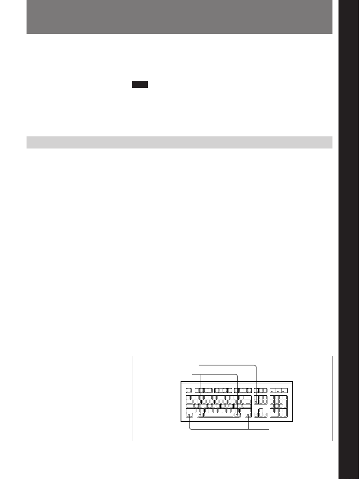
After a few moments, the message “Press Ctrl + Alt + Del to log on.”
appears.
2 Press the Delete key while holding down the Ctrl and Alt keys.
Delete key
Alt keys
Ctrl keys
(Continued)
Chapter 2 Introduction to Editing Operations 17
Page 18

Starting and Shutting Down the System
The logon screen appears.
The meanings of the fields in the logon screen are as following.
Username: The name registered when the EditStation is shipped from
the factory is “Administrator”. If other user names have been
registered, the name of the user who used the system most recently
is displayed.
Password: Nothing is registered for this field when the EditStation is
shipped from the factory. If you have registered a password, enter it
in this field.
Chapter 2 Introduction to Editing Operations
3 Enter your user name.
When you move the pointer to the user name field, its shape changes
from an arrow to a vertical line. When its shape changes, click the left
mouse button. The cursor in the user name field begins to blink to
indicate that you can enter your user name.
You do not need to carry out this step unless you have changed the
factory default assignment and wish to use a user name other than the
name displayed.
For more information about using the mouse, see page 20.
For more information about using the keyboard, see page 22.
4 Enter your password.
Move the pointer to the password field, click the left mouse button and
enter your password. The characters that you type are masked on the
screen, appearing as a row of asterisks (*****).
You do not need to carry out this step unless you have registered a
password. No password is registered when the EditStation is shipped
from the factory.
18 Chapter 2 Introduction to Editing Operations
Page 19
5 Press the Enter key on the keyboard, or move the pointer to the OK
button and click.
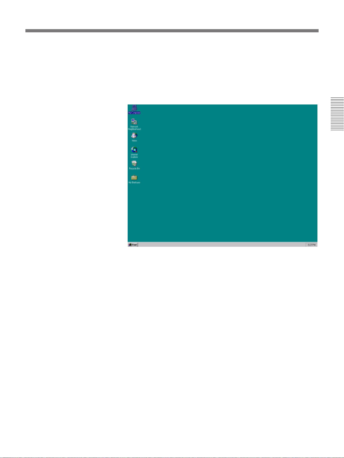
The logon procedure is completed and the desktop appears on the
screen.
You will use this window when you start to use the EditStation, and
when you turn off the power after use.
Chapter 2 Introduction to Editing Operations
Chapter 2 Introduction to Editing Operations 19
Page 20

Starting and Shutting Down the System
Using the Mouse
Moving the pointer
Learn how to use the mouse pointer by moving the mouse and checking
the movement of the pointer on the screen.
Chapter 2 Introduction to Editing Operations
Mouse pointer
Clicking
Double clicking
Pressing the left button of the mouse and then releasing it immediately is
called “clicking”. For example, “click the icon” means to move the pointer
over an icon, press the left mouse button, and then release it. (Icons are
pictures on the screen which represent programs and files.)
Unless an explanation specifically instructs you to “click the right mouse
button”, clicking is always done with the left mouse button.
Pressing the left button of the mouse and releasing it twice in rapid
succession is called “double clicking”. Note that if the interval between the
two clicks is too long, they are treated as two separate clicks, not as a
double click.
You launch the EditStation editing software by double clicking the
EditStation icon.
20 Chapter 2 Introduction to Editing Operations
Page 21
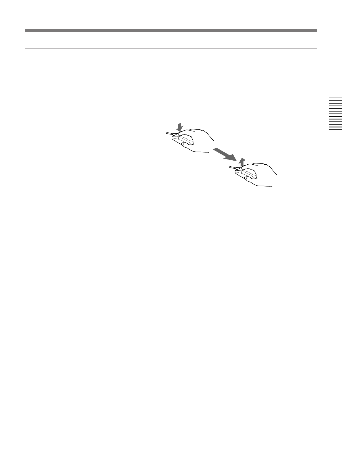
Dragging
Using the mouse to move icons and windows on the screen is called
“dragging”. To drag an item on the screen, move the pointer over the item,
press the left mouse button, and while keeping the mouse button pressed
move the pointer to the location where you want to move the item. The
movement stops at the point where you release the mouse button.
In the EditStation software, you can drag pictures of video clips to arrange
them in the desired recording order.
Chapter 2 Introduction to Editing Operations
Chapter 2 Introduction to Editing Operations 21
Page 22
Starting and Shutting Down the System
Using the Keyboar d
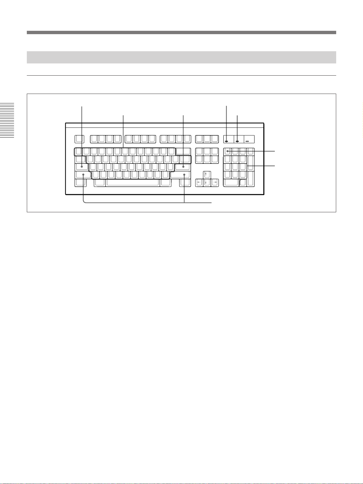
Entering text and numbers
Caps Lock key
Chapter 2 Introduction to Editing Operations
Num Lock indicator
Letter keys Enter key
Shift keys
Caps Lock indicator
Num Lock key
Numeric keypad
Entering uppercase and lowercase letters
To enter a lowercase letter or number, press the corresponding key. To
enter an uppercase letter, press the corresponding key while pressing the
Shift key.
Entering all uppercase letters
To enter all uppercase letters, press the Caps Lock key while pressing the
Shift key so that the Caps Lock indicator lights. All of the letters that you
enter will be uppercase letters.
To cancel entry of all uppercase letters, press the Caps Lock key again
while pressing the Shift key so that the Caps Lock indicator goes out.
22 Chapter 2 Introduction to Editing Operations
Entering new lines and confirming input
To enter a new line, press the Enter key. In dialog boxes, press the Enter
key after entering a file name or other input text to confirm the input.
Entering a series of numbers
The numeric keypad is convenient for entering a series of numbers. To
enter numbers with the numeric keypad, Press the Num Lock key so that
the Num Lock indicator lights.
If you press the Num Lock key so that the Num Lock indicator goes out,
the keys on the numeric keypad function as cursor keys, page movement
keys, delete key and so on.
Page 23
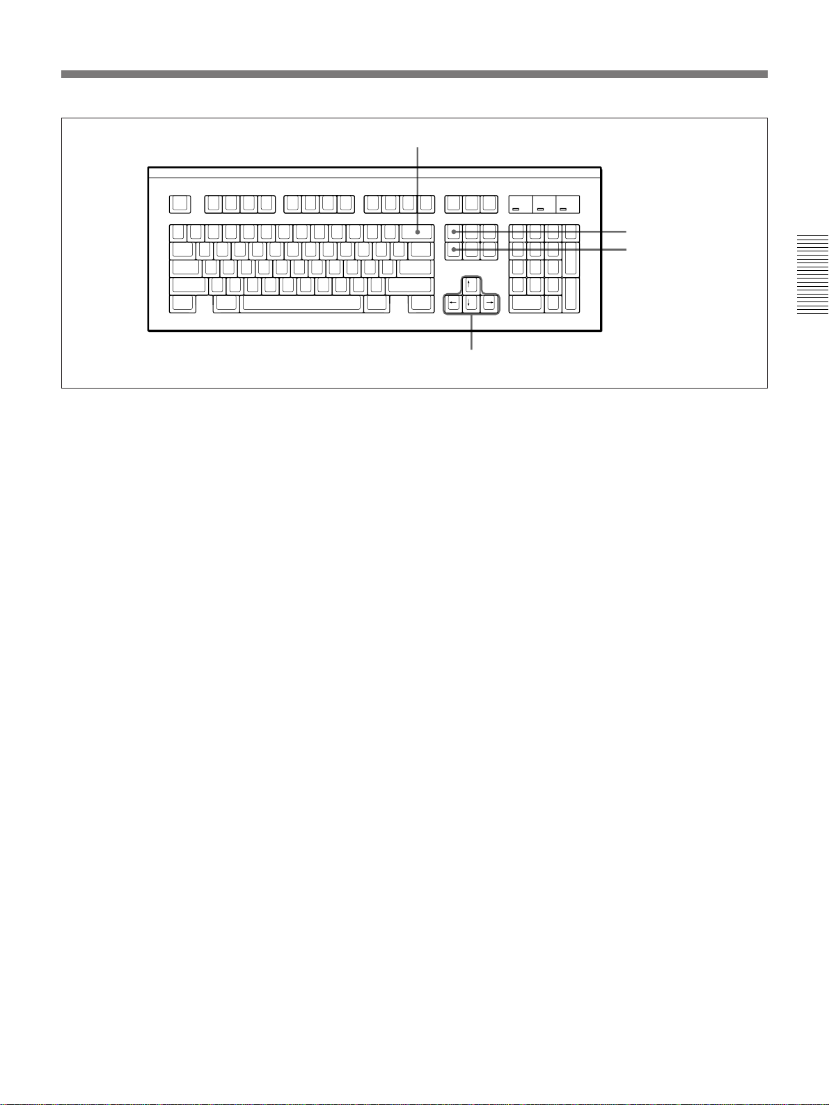
Backspace key
Insert key
Delete key
Cursor keys
Deleting text
To delete the letter before the cursor, press the Backspace key.
To delete the letter after the cursor, press the Delete key.
Moving the cursor
To move the cursor, press the ,, <, > and . keys.
Switching between insert mode and overwrite mode
To switch between insert mode and overwrite mode, press the Insert key.
Each press of the key selects insert mode or overwrite mode.
In insert mode, a letter is inserted at the cursor position when you press a
key. The letter that was formerly at the cursor position is shifted to the
right.
In overwrite mode, the letter that was formerly at the cursor position is
replaced by the new letter when you press a key.
Chapter 2 Introduction to Editing Operations
Chapter 2 Introduction to Editing Operations 23
Page 24
Starting and Shutting Down the System
Using Windows
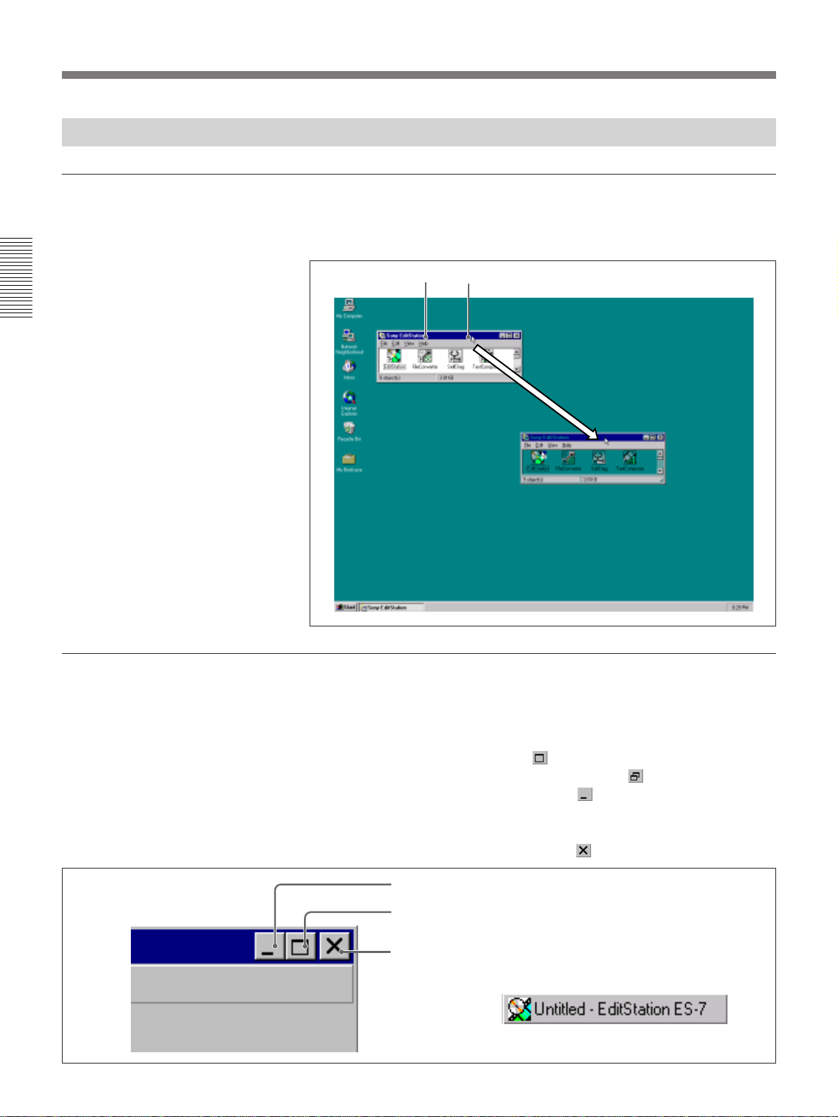
Moving windows
To move a window, move the pointer to the window's title bar and drag it
to the desired position.
Chapter 2 Introduction to Editing Operations
Drag the title bar.Title bar
Changing the size of a window
Changing the window size by clicking the window size buttons
You can use the buttons in the upper right corner of a window to change
the size of the window.
To maximize the window, click the
button.
To restore the window to its original size, click the button.
To reduce the window to an icon, click the
button. The icon appears in
the taskbar or near the lower edge of the screen. The window returns to its
original size when you double click the icon.
To completely close the window, click the
Minimize button
Maximize button
Close button
Window reduced to icon
(Click to restore to original size.)
button.
24 Chapter 2 Introduction to Editing Operations
Page 25
Selecting menu commands
Changing the window size by dragging the borders
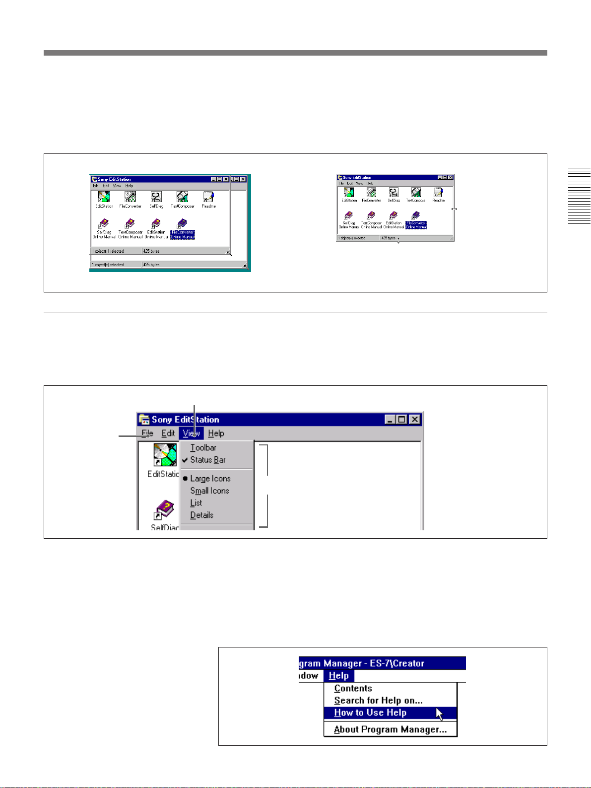
Whenever the window is not at maximum size, you can drag any of the
four corners of the window to freely adjust its size.
You can also drag the left and right borders to change the window's width
or drag the top and bottom borders to change its height.
Change the
width
Chapter 2 Introduction to Editing Operations
Change the height
Change the size
Displaying a menu command list
Directly below the title bar of a window is the menu bar. A list of menu
commands appears when you click an item in the menu bar.
Menu bar
Click here to display the commands in the View menu.
Command list
Selecting a menu command
With the command list displayed, keep the left mouse button pressed with
the pointer over the command that you want to select. The command is
highlighted and executed when you release the mouse button. This
operation is called “selecting a menu command”.
The following example shows how to select the “How to Use Help”
command from the Help menu.
Chapter 2 Introduction to Editing Operations 25
Page 26
Starting and Shutting Down the System
Scrolling to view more information
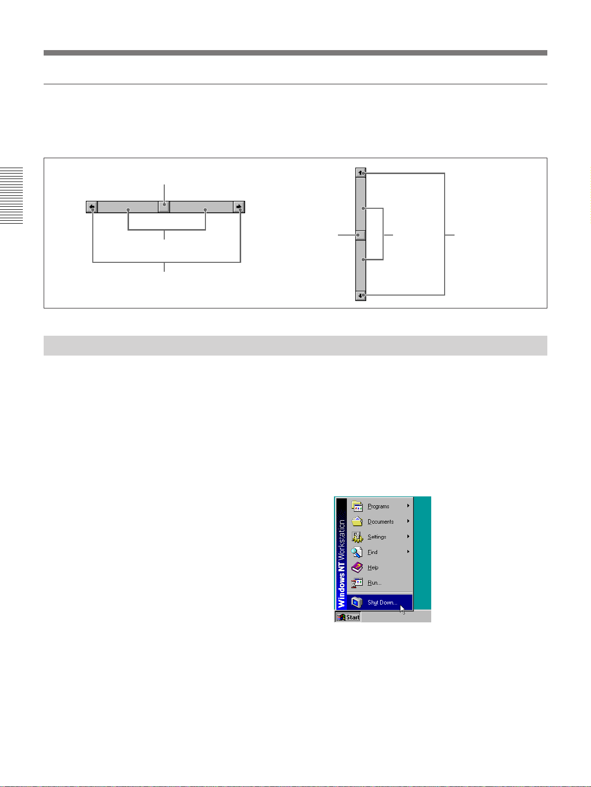
If a picture or document is too large to fit on the screen, scroll bars like the
ones shown below are displayed. You can use the scroll bars to move the
display area up or down, or left and right.
Drag to move
Chapter 2 Introduction to Editing Operations
Click to move by large amounts
Click to move by small amounts
Shutting Down the System
Drag to move Click to move
by large
amounts
Click to move by
small amounts
When you have finished using the editing software, use the following
procedure to turn off the power. In this manual, turning off the power is
referred to as “shutting down” the system.
For more information about using the mouse, see page 20.
1 Move the pointer to the Start button on the taskbar and click the left
mouse button.
The Start menu is displayed.
26 Chapter 2 Introduction to Editing Operations
Page 27
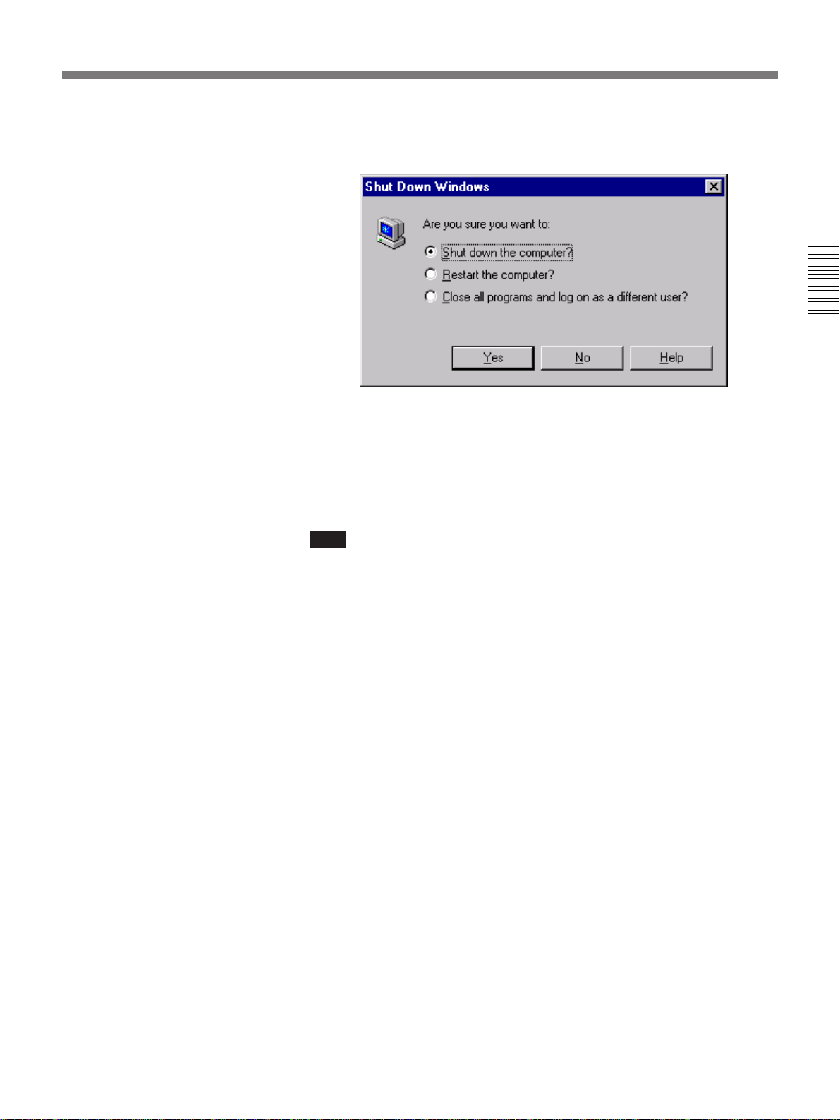
2 Move the pointer to “Shutdown” and click the left mouse button.
The Shut Down Windows dialog box appears.
3 Click “Shut down the computer?” and then click the Yes button.
After a few moments, the message “It is now safe to turn off your
computer.” appears.
4 Turn off the power.
Chapter 2 Introduction to Editing Operations
Note
This unit is equipped with an internal hard disk for storage of system files
and data other than video clips. Do not turn off the power before the
message “It’s now safe to turn off your computer.” appears. Doing so can
damage the data on the unit’s hard disk. In the worst case, you may not be
able to start the system again.
Backing up hard disk data
You should make periodic backup copies of the data on the unit’s internal
hard disk. Sony cannot be responsible for loss of data or records stored on
the hard disk because of hardware failures or any other reason.
Chapter 2 Introduction to Editing Operations 27
Page 28
The Basics of Editing With EditStation
The Basics of Editing With EditStation
This section will describe a typical editing session. It will show how to
copy materials from tape to the disk recorder, how to specify the recording
order, how to apply transitions between video clips, how to insert titles,
and other common operations. Read this section as a guide to basic editing
procedures before using the system for the first time.
This section is intended for readers who have experience in video editing
but are not familiar with Windows
Windows but have no experience in video editing.
After learning the basic editing procedures, experiment by trying other
editing operations while consulting the online manual.
Chapter 2 Introduction to Editing Operations
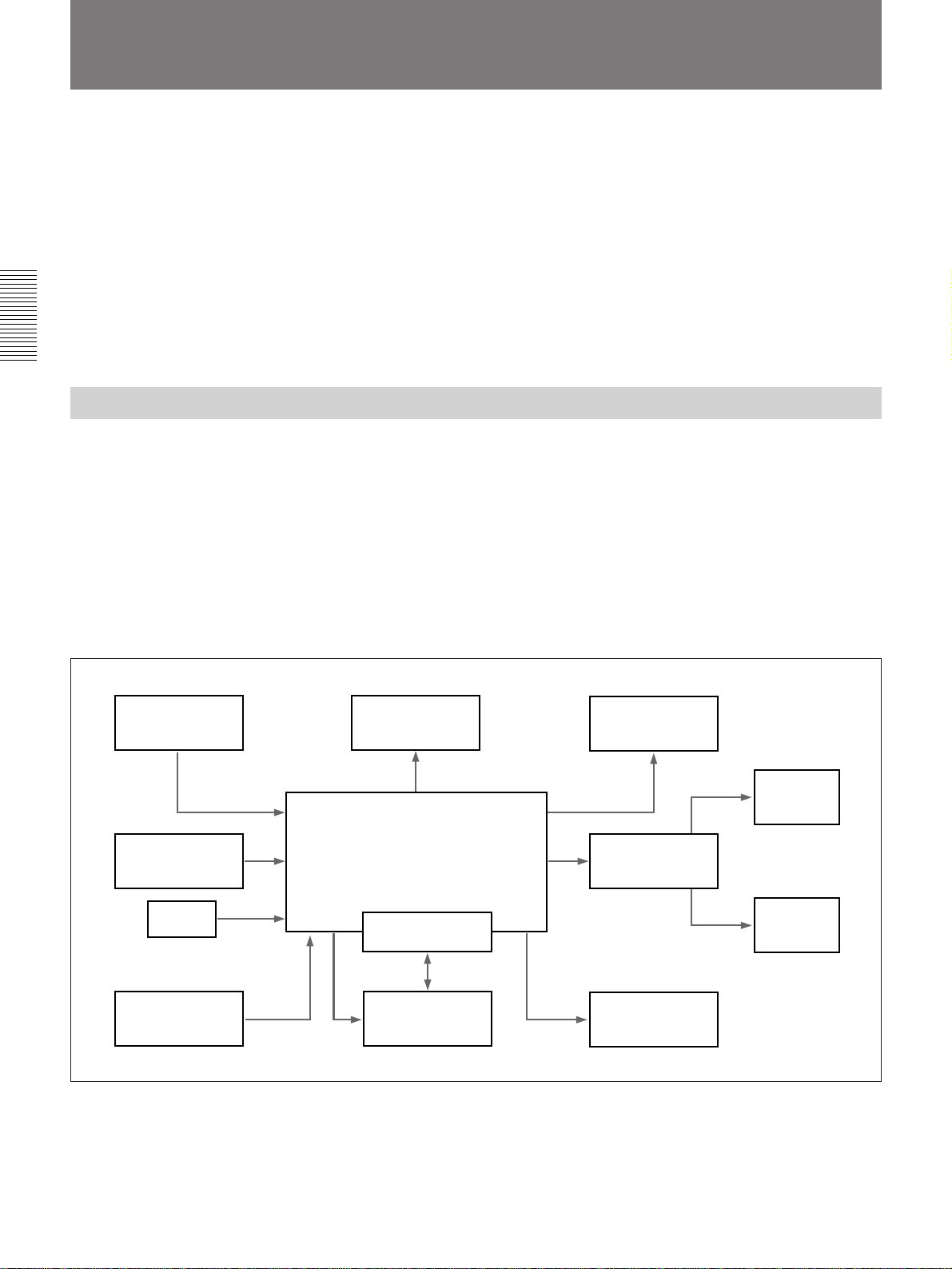
Reference Editing System
The examples in this chapter assume the use of an editing system
configured as follows.
•Player 1: PVW-2800/2800P (1)
•Recorder: PVW-2800/2800P (1)
•Disk recorder board: ESBK-7041 (1 set)
•Disk unit: ESBK-7045 (1)
•Preview monitor: PVM-1454Q/2054Q (1)
•DME switcher: ESBK-7021 Basic DME Switcher Board (1 set)
•Audio monitor: Audio amplifier (1) and speakers (2)
•Control panel: ESBK-7011 (1)
1)
or readers who are familiar with
Control panel
ESBK-7011
Keyboard (supplied)
Mouse
(supplied)
Player 1
PVW-2800/2800P
Computer monitor
ES-7 EditStation
Basic DME Switcher Board
ESBK-7021
ESBK-7045
Disk unit
Reference editing system
Preview monitor
PVM-1454Q/2054Q
Speaker
Audio amplifier
Speaker
Recorder
PVW-2800/2800P
..........................................................................................................................................................................................................
1) Windows is a trademark of Microsoft Corporation.
28 Chapter 2 Introduction to Editing Operations
Page 29
The Flow of an Editing Session
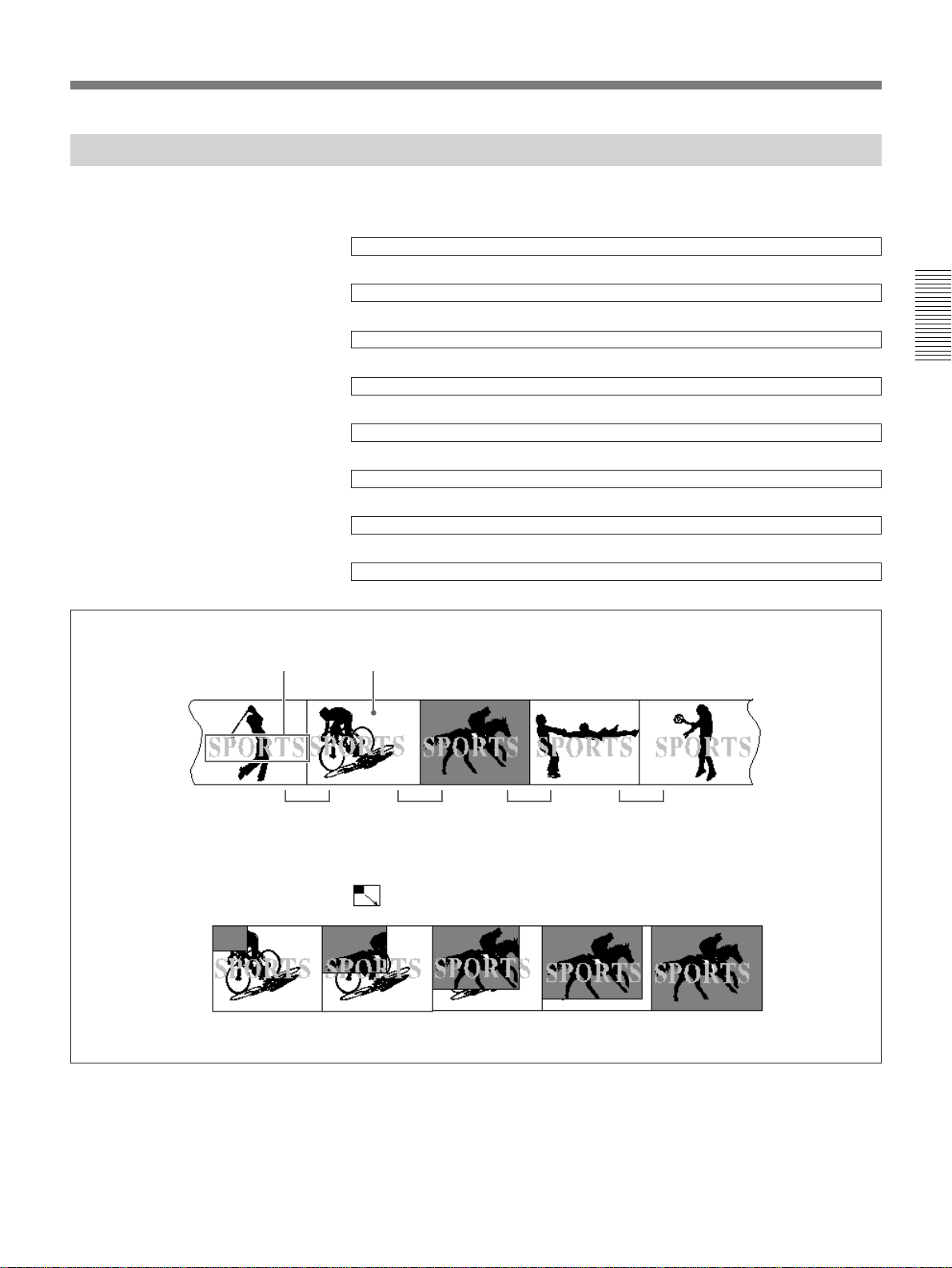
The flow of the editing session described in this chapter is as follows.
Play back a tape on the player VCR and select video clips.
.
Copy the selected video clips from the tape to the disk recorder.
.
Specify the recording order of the video clips.
.
Apply wipe effects for the transitions between video clips.
.
Apply fade-in and fade-out effects at the start and end of the sequence.
.
Insert titles over the video.
.
Record the editing results on tape.
.
Play back the recorded tape to check the finished edit.
Chapter 2 Introduction to Editing Operations
Title Video clip
Cut Effect Effect Effect
Example of wipe effect
Video clips and effects in editing example
Chapter 2 Introduction to Editing Operations 29
Page 30
The Basics of Editing With EditStation
Starting EditStation
Proceed as follows to edit with the EditStation editing software.
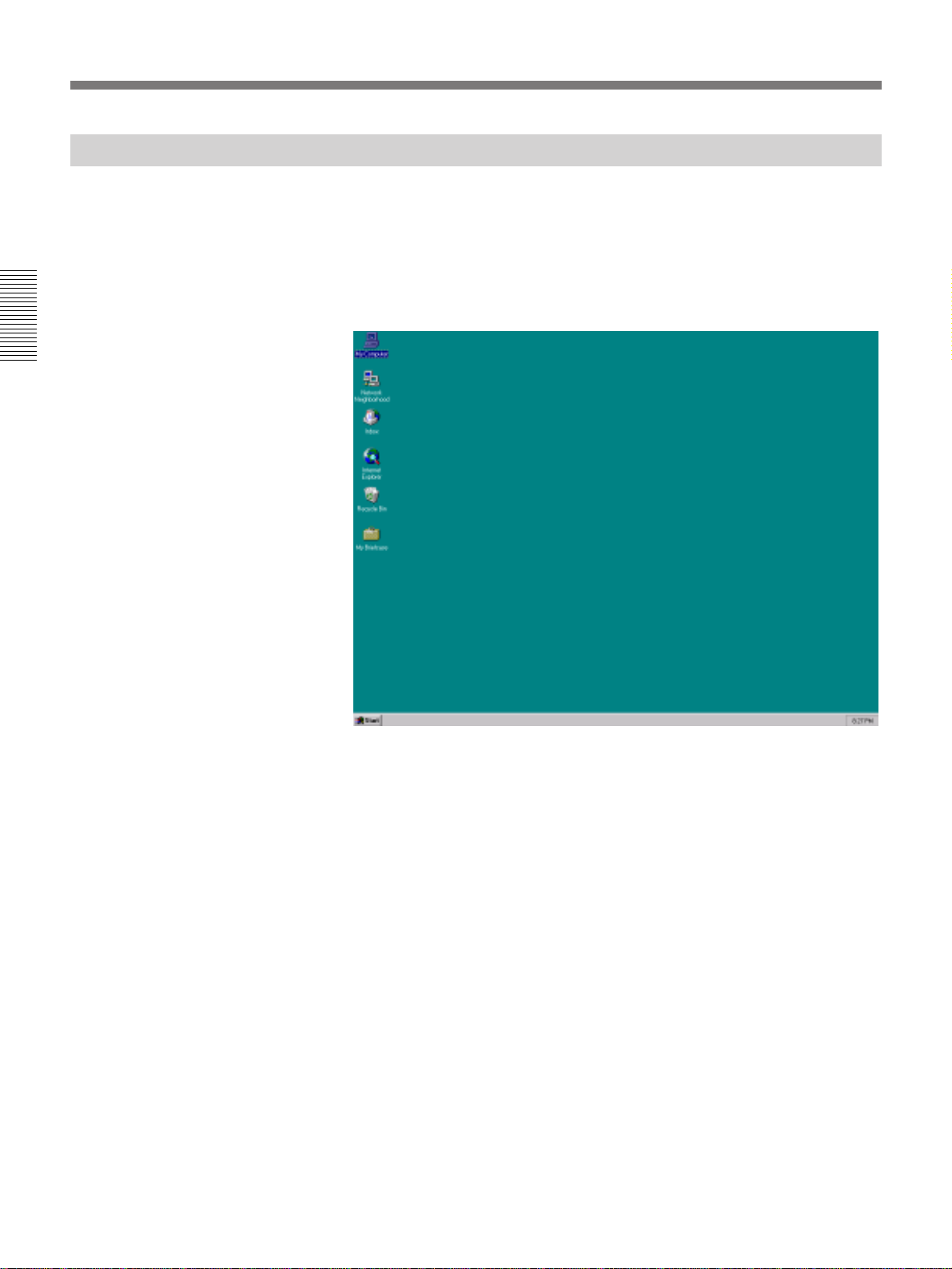
1 Start the system.
Chapter 2 Introduction to Editing Operations
For more information about starting the system, see page 17.
The desktop appears on the screen.
30 Chapter 2 Introduction to Editing Operations
Page 31

2 Click the Start button on the taskbar, move the mouse pointer to
Programs and Sony EditStation in this order, and click EditStation.
The following screen appears.
Chapter 2 Introduction to Editing Operations
To exit EditStation
This screen is called the EditStation initial screen. Most edit operations
are performed here.
See “Shutting Down the System” on page 26.
Chapter 2 Introduction to Editing Operations 31
Page 32

The Basics of Editing With EditStation
Identifying Parts of the EditStation Initial Screen
The following illustration identifies the parts of the screen that will be used
in this chapter.
Title bar (active)
1 Menu bar (active)
2 Toolbar
Chapter 2 Introduction to Editing Operations
3 Clip Bin window
4 Timeline window
1 Menu bar
Displays menu items, which you can click to display
lists of menu commands. To close a menu, click
somewhere else on the screen.
The items displayed in the menu bar and the
commands in menu lists vary depending on whether
the Clip Bin window or the Timeline window is the
active window. The active window is the window
affected by editing operations. Its title bar is
highlighted. To make a window the active window,
click somewhere in that window.
2 Toolbar
The toolbar contains a group of toolbar buttons .
Clicking one of the buttons has the same effect as
selecting a menu command. The toolbar buttons are
very convenient because they allow you to perform
common editing operations with a single click of the
mouse.
The online manual contains more information about the
functions of the toolbar buttons.
Title bar (non-active)
5 Storyboard
6 Timeline
3 Clip Bin window
The Clip Bin window is a temporary storage area for
video clips that you have created. You can assemble a
group of clips in the Clip Bin window so that they are
readily available when you are choosing clips to
record.
4 Timeline window
The timeline window is where you perform most
editing operations, such as specifying the order of edits
(the smallest unit of editing data), setting transitions
between scenes, inserting titles, and so on.
5 Storyboard
The storyboard is where you arrange edits in the order
that you want to record. You can use the storyboard to
delete and rearrange edits.
6 Timeline
The timeline displays detailed information by track
along the temporal axis of the recorder tape. This is
where you arrange, modify, and delete edits, set up
effects, insert titles, and execute editing operations
such as preview and recording. The timeline contains
several tracks for video, audio, effects and other kinds
of signals or data.
32 Chapter 2 Introduction to Editing Operations
Page 33
Preparing a Master Tape
To edit with the EditStation, you will need to prepare a tape with prerecorded black burst signals, CTL (control) signals, and timecode. This
tape is called the master tape. It is used to record the results of the edit.
If you already have a master tape, you can proceed to “Creating Video
Clips” on page 34.
If you do not have a master tape, follow the procedure below to prepare
one.
1 Insert a new tape into the recorder VCR.
If the tape has been partially played back, rewind it to the start.
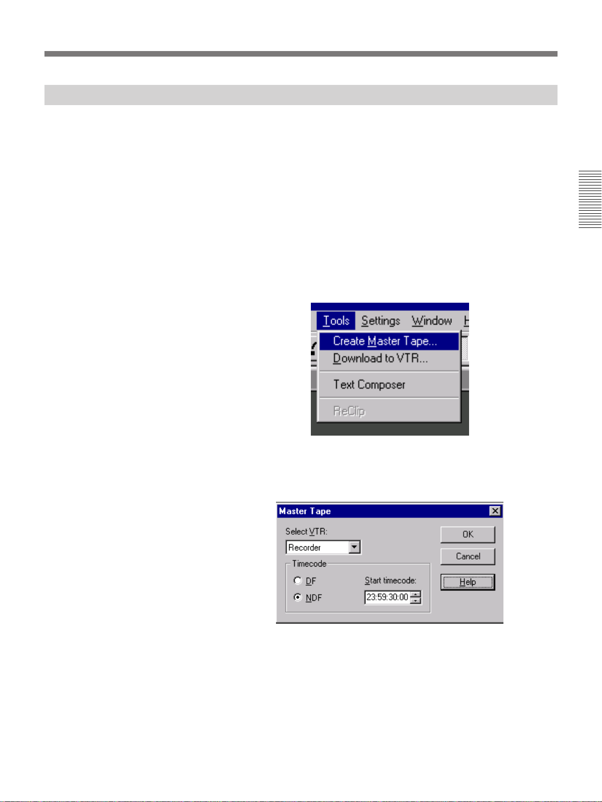
2 In the EditStation initial screen, select Create Master Tape from the
Tools menu.
The Create Master Tape dialog box appears.
3 Select RECORDER in the Select VTR field, enter 23:59:30:00 in the
Start timecode field, and click the OK button.
Chapter 2 Introduction to Editing Operations
Timecode is expressed in units of Hours:Minutes:Seconds:Frames.
Black burst signals, CTL signals, and timecode are recorded on the
entire tape from the start to the end.
Chapter 2 Introduction to Editing Operations 33
Page 34

The Basics of Editing With EditStation
Creating Video Clips
Video clips are the materials that you will use to create your edit. The first
step in an edit is to create video clips by using the following procedure.
1 Insert a tape with source materials into the player VCR.
2 In the EditStation initial screen, click the Video Clip Editor button.
Chapter 2 Introduction to Editing Operations
If the Video Clip Editor button is dimmed and cannot be selected, click
somewhere in the Clip Bin window to make it the active window.
Video Clip Editor button
Clip Bin window
34 Chapter 2 Introduction to Editing Operations
The following window appears. This is the Video Clip Editor dialog
box.
P1 (player 1) is selected as the source VCR, and the video of player 1
is displayed in the LIVE window.
LIVE window
Page 35

3 Play back the tape in player 1 to find the desired scene.
Use the following buttons.
You can also perform the same operations with the control panel.
PLAY button
[ES] button
4
3
2
1
Operation Video Clip Editor operation Control panel operation
Normal
Click ”. Press the PLAY button.
playback
Reverse
Click “. In shuttle mode, rotate the search
playback
High-speed
Click 0 or ). In shuttle mode, rotate the search
search
Low-speed
search
Still
Click 1“ or ”1 for frame-byframe playback.
Click the STILL button. Move the search dial to the center
playback
MARK OUT button
MARK IN button
Search dial
Press the search dial to toggle it
between shuttle and jog mode.
(Raised position): Shuttle mode
ø
(Depressed position): Jog mode
Ø
dial slightly in the counterclockwise
direction.
dial all the way in the clockwise or
counterclockwise direction.
In jog mode, rotate the search dial
slowly.
position. If the STILL function has
been assigned to the [ES] button,
press the [ES] button.
Chapter 2 Introduction to Editing Operations
4 Specify the start (IN point) of the video clip.
MARK IN button
Video Clip Editor: Click the MARK IN button at the desired scene.
Control panel: Press the MARK IN button at the desired scene.
MARK OUT button
Chapter 2 Introduction to Editing Operations 35
(Continued)
Page 36
The Basics of Editing With EditStation
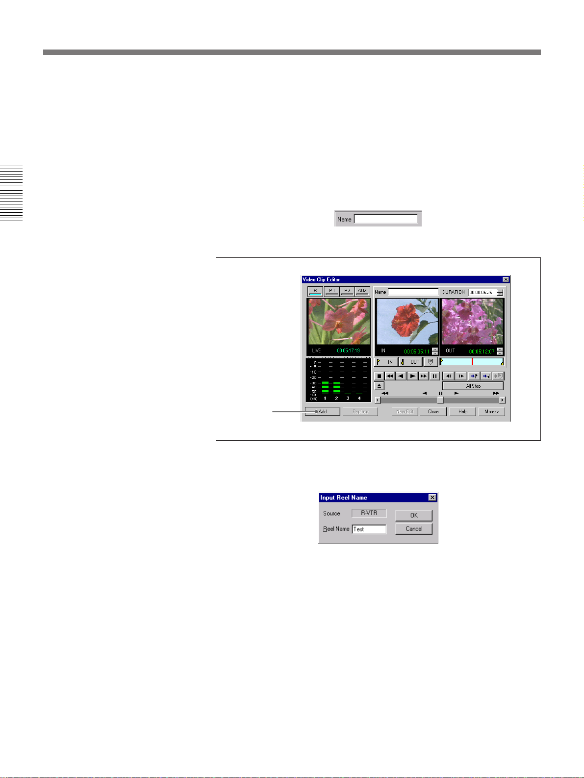
5 Specify the end (OUT point) of the video clip.
6 In the Video Clip Editor dialog box, click the Name field and enter the
Chapter 2 Introduction to Editing Operations
7 Click the Add button in the Video Clip Editor dialog box.
Video Clip Editor: Click the MARK OUT button at the desired
scene.
Control panel: Press the MARK OUT button at the desired scene.
name of the video clip.
The name can be up to 64 characters long.
Add button
A reel name dialog box like the one shown below appears once when
you create the first video clip after inserting a program materials
cassette.
Enter a reel name up to 6 characters in length and click the OK button.
An icon appears in the Clip Bin window, showing the video for the IN
point of the clip you have created.
36 Chapter 2 Introduction to Editing Operations
Page 37

Video clip icon
Video clip name
Clip Bin window
Once you have entered the reel name, you can simply click the Add
button to add more clips. However, if you change the playback VCR or
insert a new program materials cassette, you will have to enter a reel
name again after clicking the Add button.
8 Repeat steps 3 to 7 to create more video clips.
9 Click the Close button in the Video Clip Editor dialog box.
Chapter 2 Introduction to Editing Operations
Close button
The Video Clip Editor dialog box closes.
Chapter 2 Introduction to Editing Operations 37
Page 38

The Basics of Editing With EditStation
Copying Video Clips to the Disk Recorder
The next step is to copy the newly created video clips to the EditStation's
disk recorder. Copying the clips to the disk recorder is not mandatory, but
clips located on the disk recorder can be cued up instantly, for greater
editing efficiency.
Proceed as follows to copy the clips.
1 While holding down the Ctrl key on the keyboard, click the Clip Bin
Chapter 2 Introduction to Editing Operations
window icon for the clip that you want to copy.
The frame of the selected clip changes color from black to light blue. If
you wish, you can select several clips at once.
Frame changes to light blue
2 Select Upload to Disk Recorder from the Clip menu, and then select
Selected.
Player 1 begins to play back the tape and the clips selected in step 1 are
copied to the disk recorder.
The disk indicators of the clips that have been copied to the disk
recorder light in green.
Disk indicator
38 Chapter 2 Introduction to Editing Operations
Page 39

Editing With Cut T ransitions
A cut is a transition in which one scene is replaced instantly by another
scene. If you have arranged your clips in the timeline and have not
specified otherwise, the transitions between scenes will be cuts.
The following procedure uses cuts to link scenes [D], [C], and [B].
1 Drag video clip [D] from the Clip Bin window to the timeline.
See page 21 for more information about dragging.
Chapter 2 Introduction to Editing Operations
2 Drag video clips [C] and [B] in that order from the Clip Bin window to
the timeline.
To avoid that a gap is made on the timeline between the existing clip
and a new clip, drag the new clip so that its left end portion overlaps
the right end portion of the existing clip, then release the left mouse
button.
This specifies cut transitions between video clips [D] and [C] and video
clips [C] and [B].
Chapter 2 Introduction to Editing Operations 39
Page 40
The Basics of Editing With EditStation
Previewing the Edit Results
A preview is a rehearsal in which you play back the edited video to check
whether you have achieved the results you want. A preview is not recorded
by the recorder.
In this section we will conduct a preview to check the results of our cut
editing.
To conduct a preview, proceed as follows.
Chapter 2 Introduction to Editing Operations
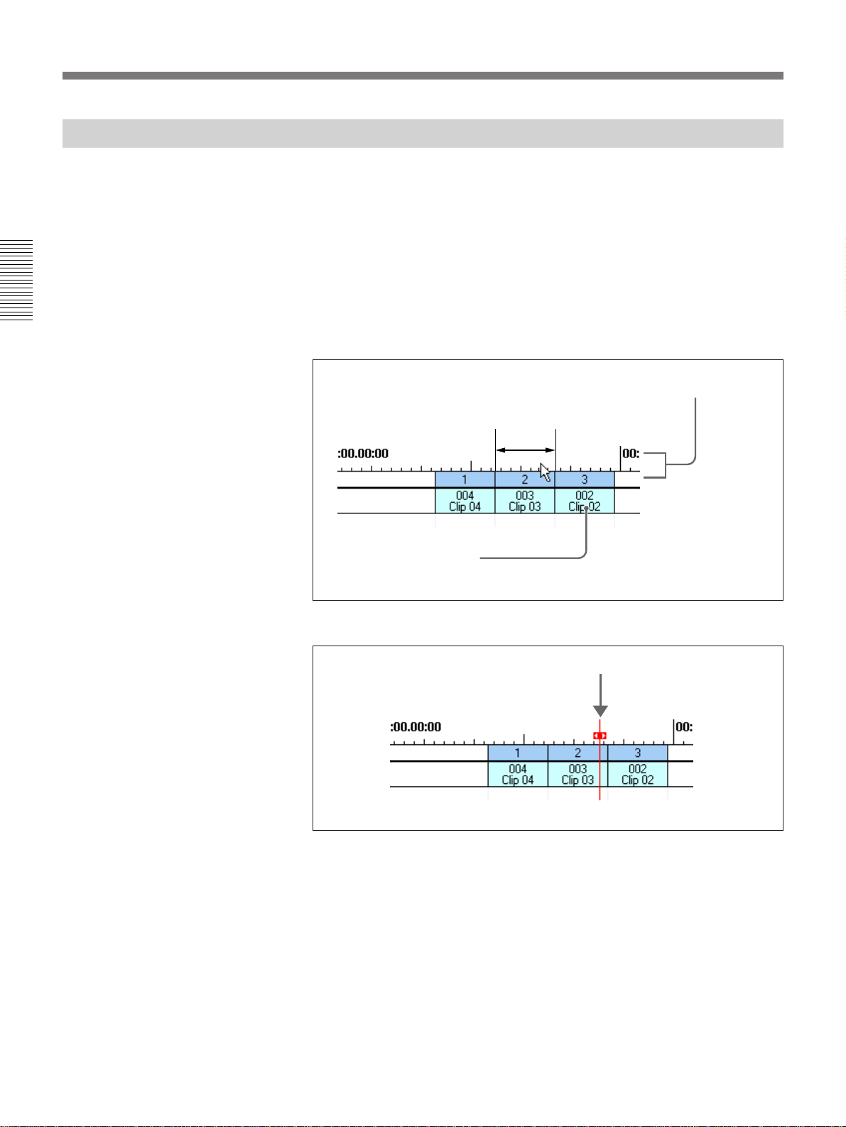
1 Click the timecode ruler at any point above the edit
1)
positioned
immediately before the edit where you want to start the preview.
Timecode ruler
Click within
this range
Start the preview from this edit
The timeline cursor2) moves to the clicked position.
Timeline cursor
..........................................................................................................................................................................................................
1) An edit is the smallest unit of editing data. Edits are
shown on the timeline as rectangular frames. Each edit
corresponds to a specific video clip in the Clip Bin
window.
2) The timeline cursor is the cursor that shows the current
position on the timeline. Video under the timeline cursor
is displayed on the video monitor.
40 Chapter 2 Introduction to Editing Operations
Page 41

2 Click the Preview button.
Preview button
The timeline cursor moves to the start of the next edit and the preview
begins from that point. The preview video is displayed on the video
monitor.
The timeline cursor moves to
the start of the edit.
In the example on page 39, when a preview is executed from the first edit,
[D], [C], and [B] are played back in order with a cut transition between
each scene.
After conducting a preview, make any adjustments that may be necessary
and proceed to the next stage in the editing.
Stopping a preview before it finishes
Click the All Stop button on the screen, or press the ALL STOP button on
the control panel.
Chapter 2 Introduction to Editing Operations
All Stop button
Chapter 2 Introduction to Editing Operations 41
Page 42
The Basics of Editing With EditStation
Adjusting Edit Points
If a preview shows that you need to adjust the duration of a clip, adjust the
clip’s IN point or OUT point.
Adjusting the Positions of IN Points and Out Points
Proceed as follows.
Chapter 2 Introduction to Editing Operations
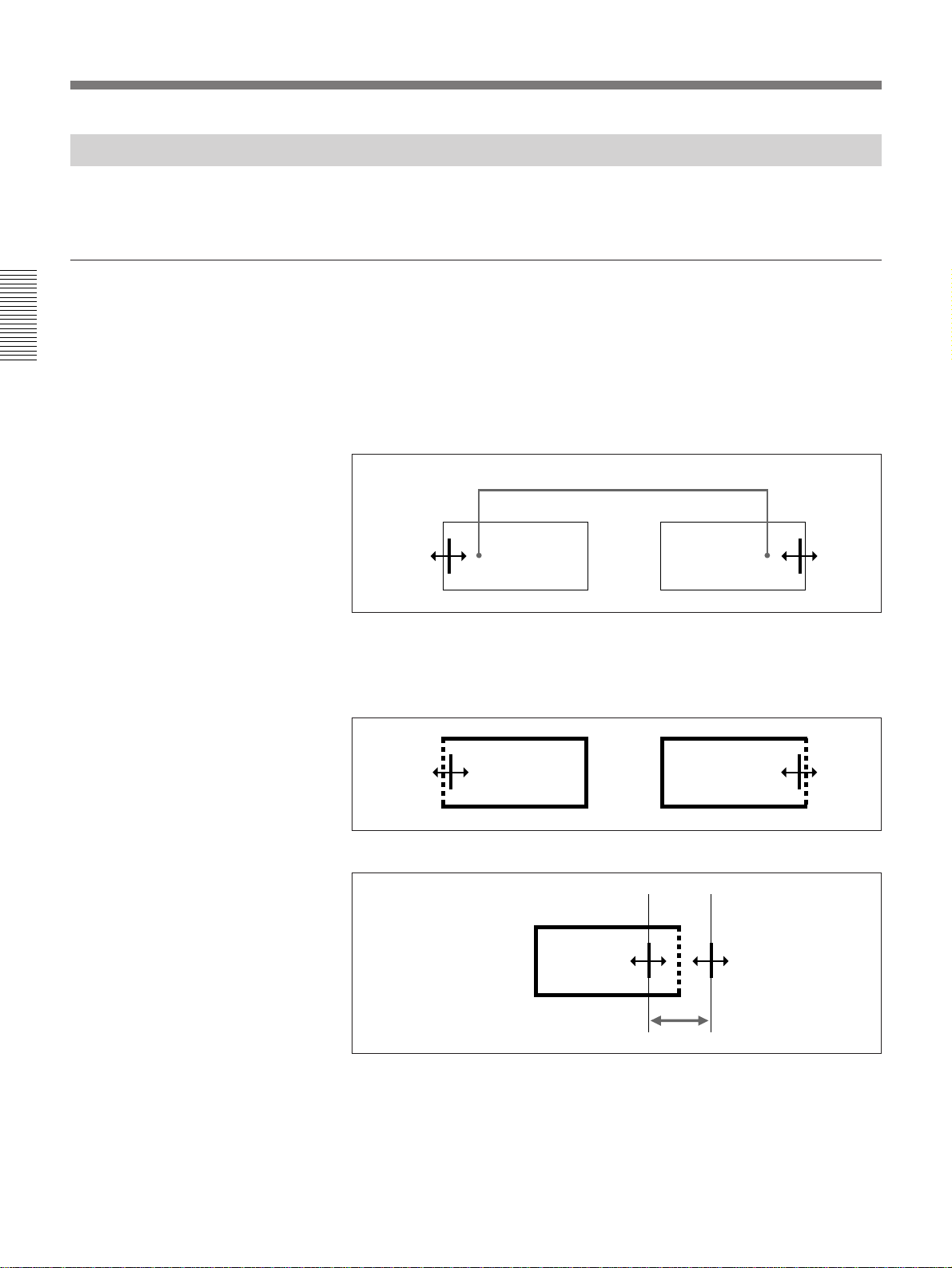
1 To adjust the IN point or OUT point, move the mouse pointer to a
position, slightly inside the left edge or right edge of a clip on the
timeline.
The pointer shape changes as shown below.
Video clip on the timeline
2 Click the left mouse button.
The clip frame becomes thicker, and the left edge or right edge
changes to a broken line.
42 Chapter 2 Introduction to Editing Operations
3 With the mouse left button pressed, drag to the left or right.
To adjust edit points in units of frames
You can use the Trim Editor and Video Clip Editor dialog boxes to adjust
edit points in units of frames. However, you cannot use the Video Clip
Editor to adjust the edit points of clips on the timeline.
For more information about the Trim Editor and Video Clip Editor dialog boxes,
refer to the online manual.
Page 43

Points to note when increasing the duration of a video clip
In the factory default configuration, video from 2 seconds before the IN
point to 2 seconds after the OUT point is copied to the disk recorder when
you copy video clips from tape to the disk recorder. Therefore, you cannot
add more than 2 seconds at the start and end of a clip when working with
clips stored on the disk recorder.
If you wish, you can increase the length of video recorded at the start and
end of a clip to more than 2 seconds. Make the Clip Bin window the active
window, select Options from the Settings menu, and set the desired length.
As shown in the figure below, you can begin by copying a video clip with
more than enough duration to the disk recorder and then create shorter
clips from the longer clip. In this case there is no limitation on the
adjustment of edit points, even when you are working with clips stored on
the disk recorder.
Long clip stored on the disk recorder
AB
Chapter 2 Introduction to Editing Operations
Create shorter clips from
AB
In this illustrated case, only the long clip is created on the disk recorder
but neither clip [A] nor [B] is created there.
If you know in advance that you may want to change the edit points of a
video clip, you should normally start by uploading a longer clip to the disk
recorder, or use the Settings menu to change the factory default length.
the long clip.
Chapter 2 Introduction to Editing Operations 43
Page 44

The Basics of Editing With EditStation
Adding Wipe Effects
A wipe is a transition effect in which one scene gradually expands to
replace another scene. This section will explain an example that adds two
types of wipe transition, and then uses a cut as the third transition. When
you preview after adding the wipes, the scenes change as shown below.
Wipe pattern
Chapter 2 Introduction to Editing Operations
Video clip
AB
Edit results
A
None (cut)
CD
BB
Proceed as follows.
B
1 Click the effect button at the top of the Timeline window.
C
Effect button
DCC C D
44 Chapter 2 Introduction to Editing Operations
The Effect dialog box opens.
2 Click the Wipe tab in the Effect dialog box.
Wipe tab
This shows wipe patterns.
Page 45

3 On video track V1 or V2, click the edit that you want to remain as the
scene after the wipe transition.
The frame of the clicked edit becomes thicker to show that the edit is
selected.
4 Select a wipe pattern and then click the Auto Add button.
Chapter 2 Introduction to Editing Operations
The wipe pattern is displayed on the Effect track. The edit that will be
visible when the wipe finishes moves automatically to the V2 track.
There is an overlap between the edits visible before and after the wipe.
The length of the overlap is equivalent to the duration of the wipe.
Overlap
(Continued)
Chapter 2 Introduction to Editing Operations 45
Page 46

The Basics of Editing With EditStation
5 Move the third clip leftwards so that an overlap is generated, and place
the wipe pattern on the overlap.
The timeline now appears as shown below.
Chapter 2 Introduction to Editing Operations
About edit blocks
6 Click the Close button in the Effect dialog box.
The Effect dialog box closes.
When you add an effect, such as wipe, that involves a transition between
scenes, neighboring blocks on the timeline are joined into a single block.
This kind of block on the Edit track is called an edit block.
Two neighboring blocks...
become a single block.
46 Chapter 2 Introduction to Editing Operations
Page 47
Adding Fade-in and Fade-out Effects
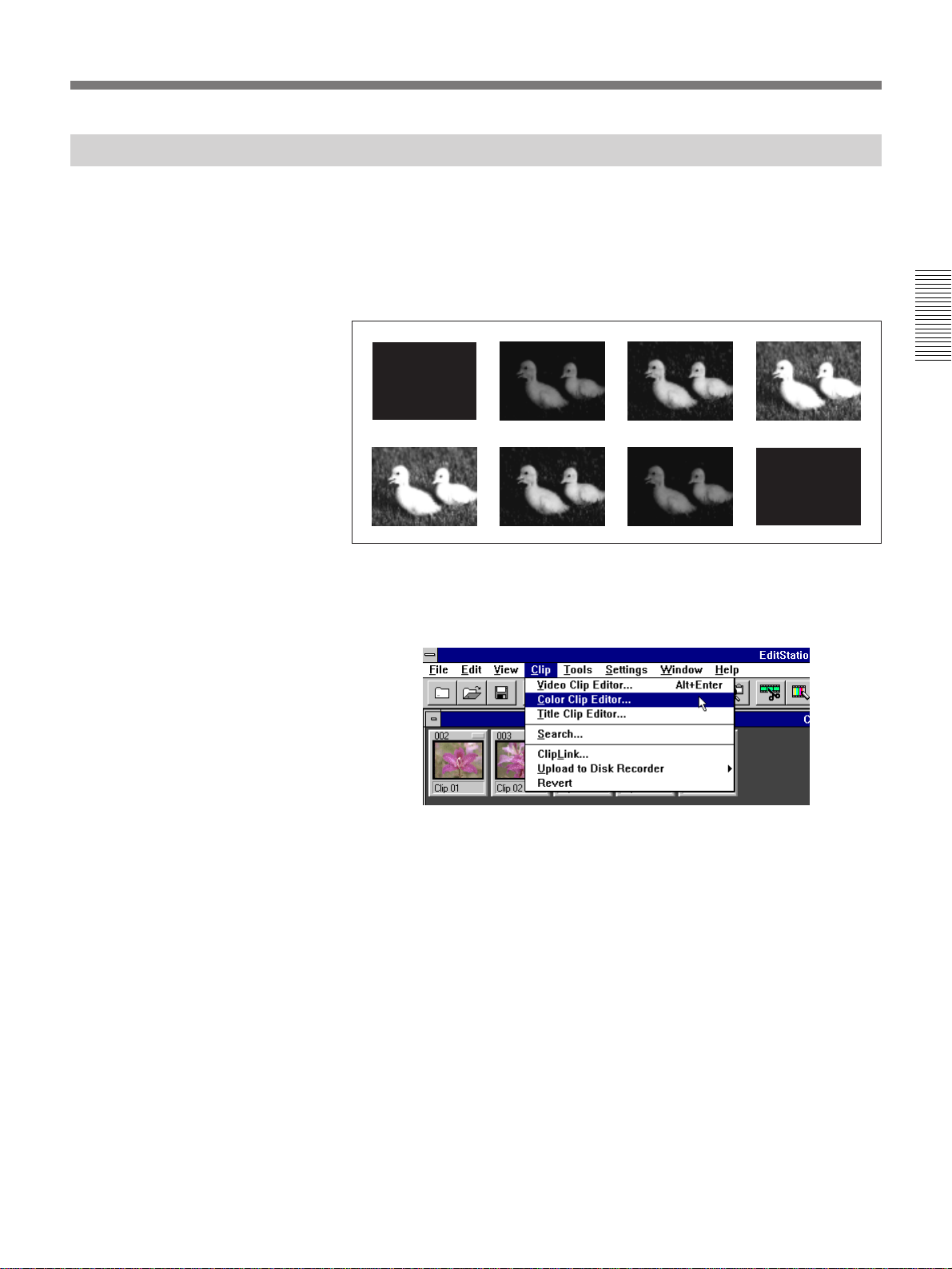
Fade in and fade out are effects in which the video appears or disappears
gradually.
This section will explain an example that uses a black clip background to
fade in from black and to fade out to black. The procedure uses the
Dissolve tab of the Effect dialog box. Dissolve is another effect in which
video appears or disappears gradually.
Proceed as follows.
1 Make the Clip Bin window the active window and select Color Clip
Editor from the Clip menu.
Fade in
Chapter 2 Introduction to Editing Operations
/ / /
Fade out
/ / /
The Color Clip Editor dialog box appears.
Chapter 2 Introduction to Editing Operations 47
(Continued)
Page 48

The Basics of Editing With EditStation
2 Clip the Black tab and enter 00:00:02:00 in the Duration field.
Chapter 2 Introduction to Editing Operations
3 Click the Add button and then the Close button.
The duration is expressed in units of Hours:Minutes:Seconds:Frames.
This example creates a clip that displays a black picture for 2 seconds.
A black clip icon appears in the Clip Bin window and the Color Clip
Editor dialog box closes.
4 Drag the black clip icon from the Clip Bin window to the beginning
and end of the edits on the timeline so that overlaps are generated.
48 Chapter 2 Introduction to Editing Operations
Page 49

5 Click the effect button in the Timeline window.
Effect button
The Effect dialog box appears.
6 Click the Dissolve tab in the Effect dialog box.
Dissolve tab
Chapter 2 Introduction to Editing Operations
(Continued)
Chapter 2 Introduction to Editing Operations 49
Page 50
The Basics of Editing With EditStation
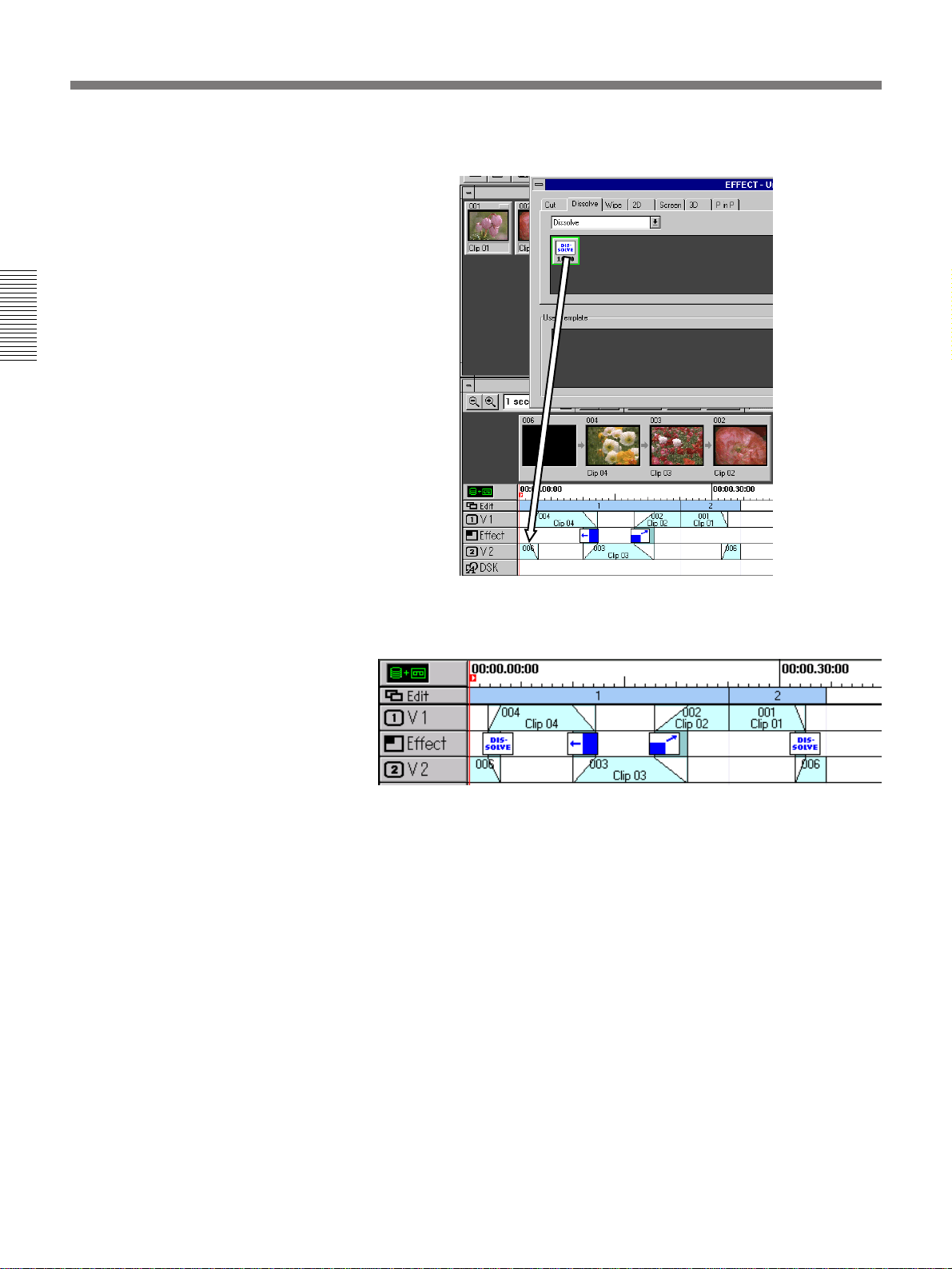
7 Drag the dissolve icon to the overlap at the beginning of the Effect
Chapter 2 Introduction to Editing Operations
track.
8 Drag the dissolve icon to the overlap at the end of the Effect track.
As shown below, a dissolve effect is set for the first and final edits.
9 Click the Close button of the Effect dialog box.
The Effect dialog box closes.
50 Chapter 2 Introduction to Editing Operations
Page 51

Inserting a Title
Creating a title
The flow of operations for inserting a title into video is as follows.
To prepare the title text, use the Text Composer software that comes preinstalled on the system. You can call Text Composer from within
EditStation.
Launch the Text Composer software with an EditStation command.
.
Create the title.
.
Save the title on the internal hard disk and quit Text Composer.
.
Open the Title Clip dialog box in EditStation and read in the newly created title.
.
Specify a length of time to display the title.
.
Drag the title icon to the DSK track.
Chapter 2 Introduction to Editing Operations
Proceed as follows to create a title.
1 Select Text Composer from the Tools menu.
Text Composer is launched, and the following screen appears on the
video monitor. This is the Text Composer main screen.
(Continued)
Chapter 2 Introduction to Editing Operations 51
Page 52

The Basics of Editing With EditStation
2 Click the create text button on the main menu, use the mouse to move
Chapter 2 Introduction to Editing Operations
3 Enter the title from the keyboard and click somewhere on the screen
the text cursor (the vertical line) to the position on the screen where
you want to insert the title, and click the position.
Create text button
away from the title text to confirm the input.
The title that you entered is displayed on the video monitor with edge
and shadow effects.
For details about changing the size and color of the title and adding or
removing edge and shadow effects, refer to the online manual.
4 Click the File button on the main menu.
52 Chapter 2 Introduction to Editing Operations
The File menu appears.
Page 53

5 Click the Save button on the File menu.
The Save dialog box appears.
6 Click the With Image check box to make a check mark appear in the
box, enter a file name for the title file in the name field, and click the
OK button.
File names can be up to 256 characters in length, and can contain
spaces. Uppercase letters are distinguished from lowercase letters. For
this example, enter the file name “Title 1” and click the OK button.
Chapter 2 Introduction to Editing Operations
When you click the OK button, the screen returns to the main menu.
7 Click the File button on the main menu and click the Quit button on
the File menu.
The Text Composer screen closes.
Chapter 2 Introduction to Editing Operations 53
Page 54

The Basics of Editing With EditStation
Inserting a title into the video
Proceed as follow to insert a title into the video.
1 Make the Clip Bin window the active window and select Title Clip
Chapter 2 Introduction to Editing Operations
2 Click the Still tab, and then click the Browse button.
Editor from the Clip menu.
The Title Clip Editor dialog appears.
Browse button
A dialog box appears so that you can browse the hard disk for the title
file created earlier.
54 Chapter 2 Introduction to Editing Operations
Page 55
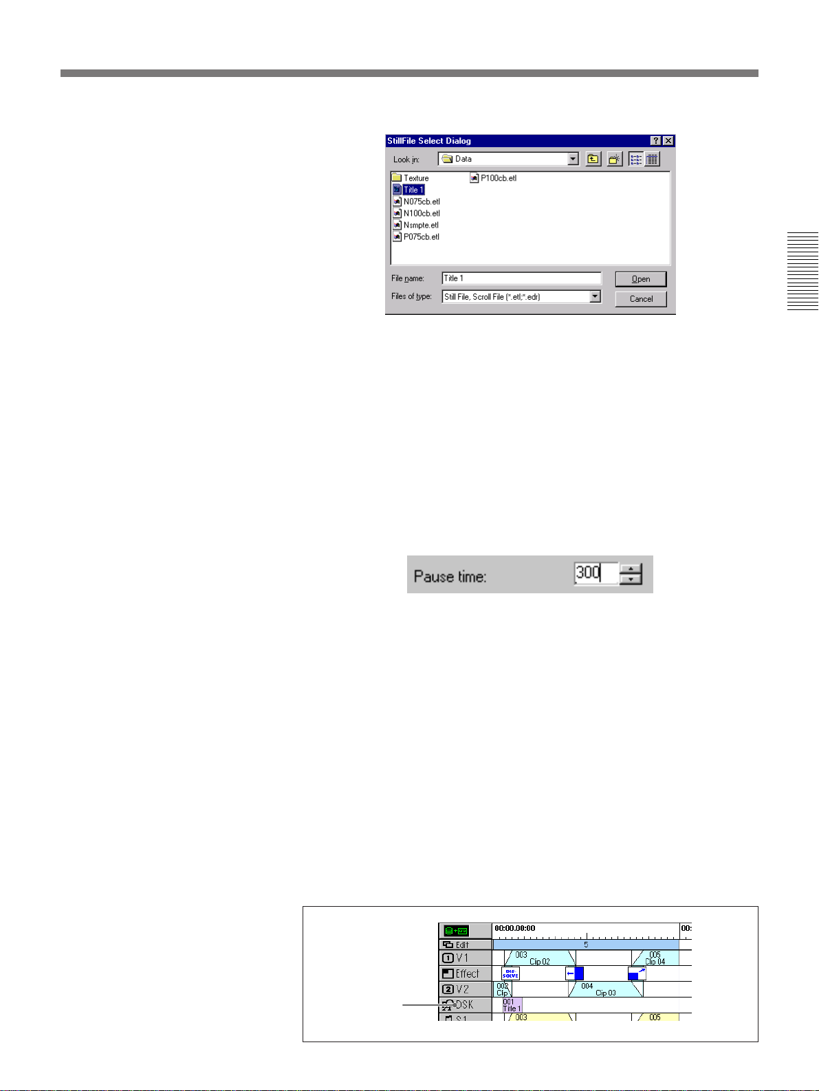
3 Select the DATA folder on drive C.
In the “Look in” field, double click the (C:) icon to show the folders
under it. (If the icon displayed in the “Look in” field is not (C:), first
click the down arrow button to the right of the field.) Find the ES-7
folder icon and doubl click it. Then find the Data icon and double
click it.
4 Select “Title 1.edr” from the file list by clicking it, and then click the
OK button.
The title that you created earlier is read in.
Chapter 2 Introduction to Editing Operations
5 Enter 300 in the Pause Time box.
Enter the pause time value in units of “seconds: frames”. You do not
need to enter the colon ( : ). The title will be displayed for the length of
time specified in this field.
6 Click the Add button, and then the Close button.
A title clip icon appears in the Clip Bin window and the Title Clip
Editor dialog box closes.
7 Drag the title clip icon from the Clip Bin window to the DSK track.
To adjust the position of the title clip on the DSK track, click the title
clip icon, click the magnifying glass button in the Timeline window,
and press the < and , keys on the keyboard.
In the position shown below, the title will be superimposed over the
video of clip 003 for about 3 seconds after completion of the fade in.
DSK track
Chapter 2 Introduction to Editing Operations 55
Page 56

The Basics of Editing With EditStation
Previewing the edit results
The steps above complete the operations required for this example.
Before recording, it is a good idea to conduct a preview to check the
overall contents and make sure that you achieved the results you wanted. If
necessary, you can then go back and make any required adjustments.
To conduct a complete preview, proceed as follows.
Chapter 2 Introduction to Editing Operations
1 Make the Timeline window the active window and select Set Timeline
Cursor from the Execute menu.
A timecode input dialog box appears.
2 Enter 00:00:00:00 in the text box and click the OK button.
56 Chapter 2 Introduction to Editing Operations
The timeline cursor moves to the left edge of the timeline.
You can click the left edge of the timeline ruler to move the timeline
cursor all the way to the left.
3 Click the Preview button.
Preview button
The preview starts from the first edit on the timeline.
Page 57

Recording the Edit Results
Checking the recording
If the preview revealed no problems, you are ready to record the edit
results on tape.
To record, make the Timeline window active and select Download to VTR
from the Tools menu.
Chapter 2 Introduction to Editing Operations
The recorder tape begins to run and the edit results are recorded. The
recorder tape stops automatically when recording finishes.
To check what you have recorded, proceed as follows.
1 Click the clip icon in the Clip Bin window.
The Video Clip Editor dialog box opens.
2 Click the R button above the LIVE window.
The recorder VCR becomes the source VCR.
3 Use the tape transport control buttons in the Video Clip Editor dialog
box to rewind the tape to the beginning and play it back.
The video recorded on the tape appears on the video monitor.
Chapter 2 Introduction to Editing Operations 57
Page 58
The Basics of Editing With EditStation
Saving the Edit File
After finishing the edit, you will want to save the edit file. The file saved at
this point contains the video clips, effects, titles, and other data that were
used in the editing. Saving the data in a file allows you to recreate the edit
results. For example, you can work up to the preview stage, and come back
the next day to record the edit results.
Proceed as follows to save the edit data in a file.
Chapter 2 Introduction to Editing Operations
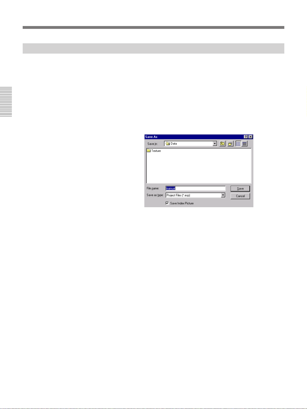
1 Select Save As from the EditStation File menu.
The Save As dialog box appears.
2 Enter the file name and click the OK button.
The file name can be up to 256 characters long. Specify “.esp” as the
extension at the end of the file name.
The current state of every EditStation window is saved in the file,
enabling you to come back and pick up where you left off.
To open the edit file, select Open from the EditStation File menu and
enter the file name.
58 Chapter 2 Introduction to Editing Operations
Page 59

Using the Online Manual
In real-life editing situations, the basic operations described in this chapter
will not be enough. You will need more detailed information about
advanced operations and settings. The online manual is a detailed guide
with information about every aspect of the EditStation.
To use the online manual, proceed as follows.
1 Select Contents from the EditStation Help menu.
The Contents tab of the Help Topics window appears.
The book icons represent topics organized by category. To view the
topics in a category, click the book icon and then click the Open
button. The book opens and the topics appear. To close a book and
remove the topics from the screen, click the book and then click the
Close button.
Chapter 2 Introduction to Editing Operations
The [?] icons represent the help topics in a category.
2 To view the contents of a topic, click the [?] icon and then click the
Display button.
The contents of the topic are displayed.
Chapter 2 Introduction to Editing Operations 59
Page 60
The Basics of Editing With EditStation
To return from a help topic to the Contents
Click the Contents button.
Using jumps and glossary definitions to find information
Chapter 2 Introduction to Editing Operations
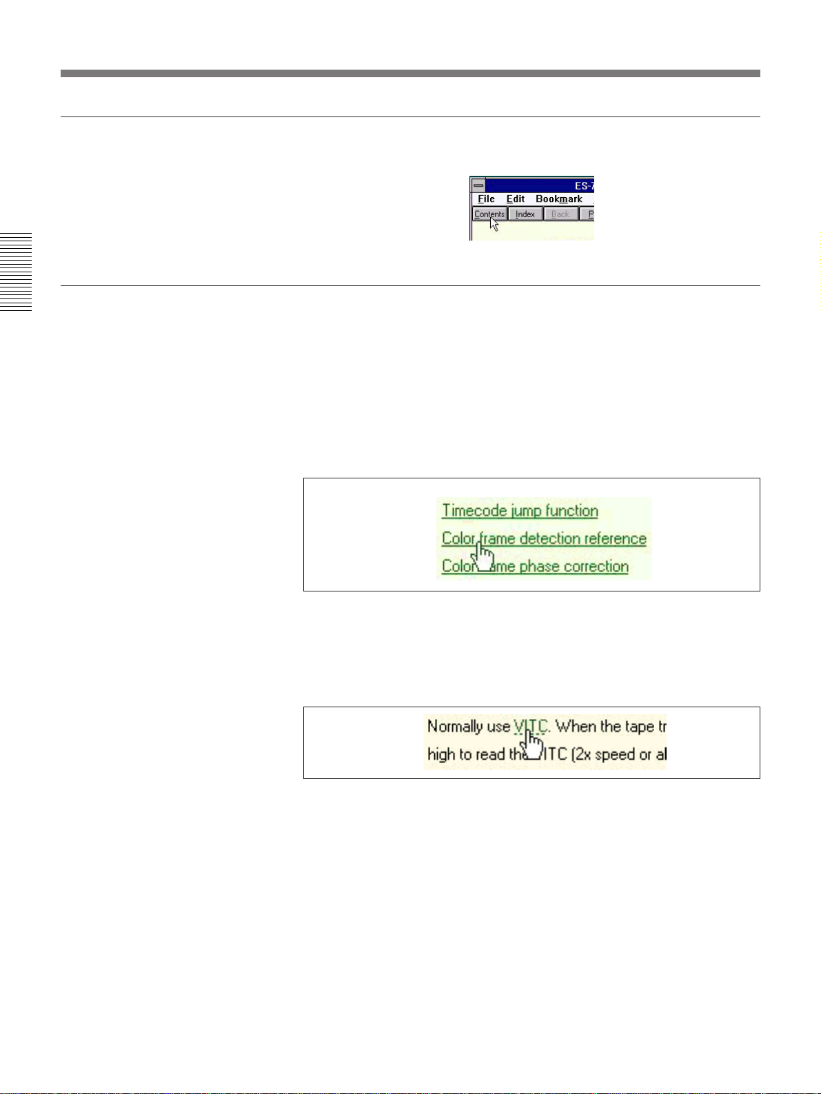
Most help topics contain jumps and glossary definitions: words that are
underlined and displayed in green to indicate that they lead to further
information.
Jumps
Jumps are displayed in green with a solid underline. You can click a jump
to go to another topic with related information. To return from a jump,
click the Back button at the top of the Help window.
Glossary definitions
Glossary terms are displayed in green with a dotted underline. When you
click a glossary term, a pop-up window appears with a definition of the
term. To remove the definition from your screen, click anywhere on your
screen, or press the ESC key.
60 Chapter 2 Introduction to Editing Operations
Page 61
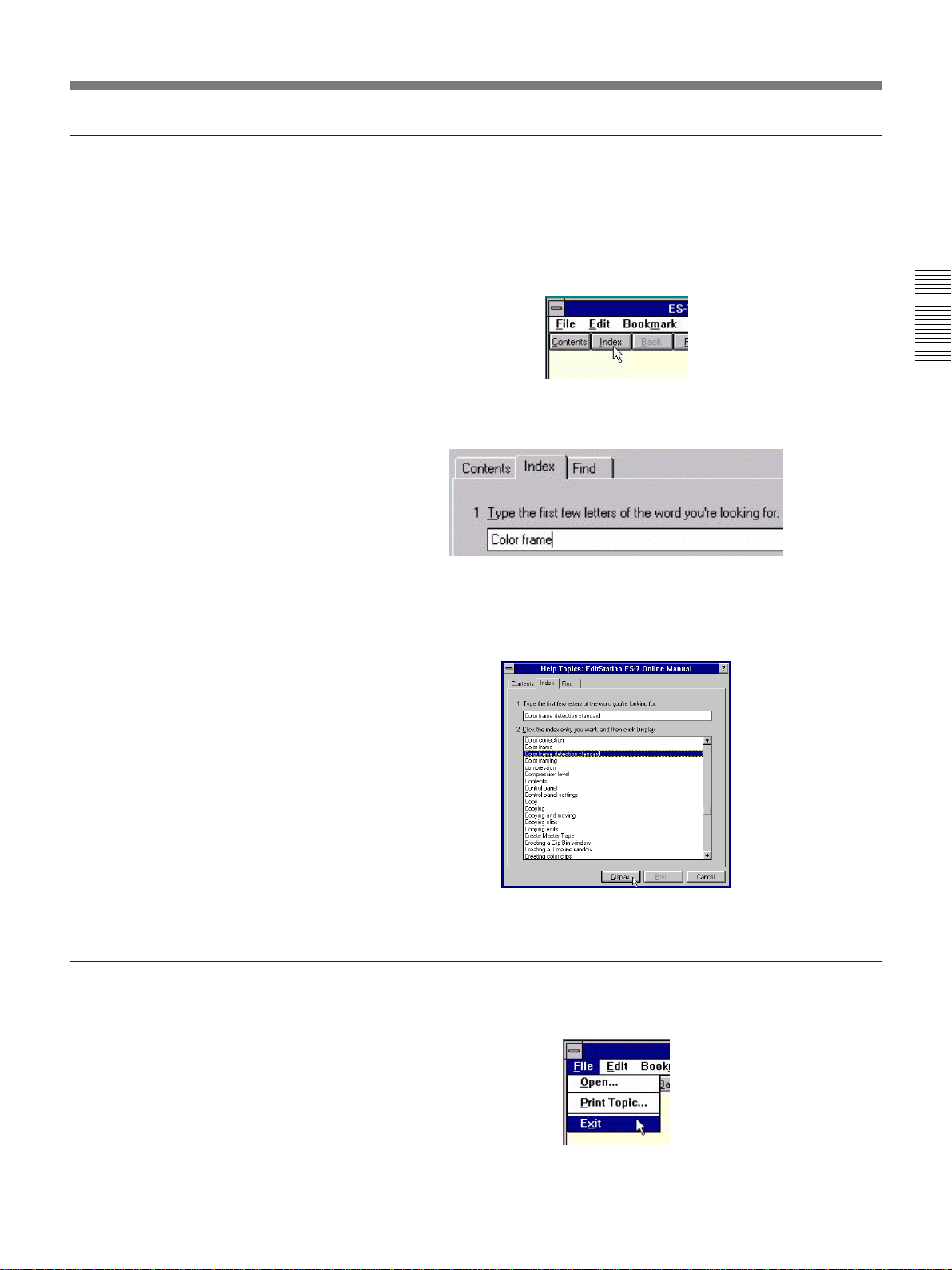
Using Index to find information
When you want to find information about a certain word, you can use the
Index tab to display all topics associated with that word.
To search for information using Index, proceed as follows.
1 Click the Index button of the Help Topics window.
Chapter 2 Introduction to Editing Operations
2 Type a word, or select one from the list of matching words. Then click
Display.
A list of topics associated with that word is displayed.
To close the online manual
3 Select the topic that you want to view, then click Display.
The Help topic that you selected is displayed.
Select Exit from the File menu of the Help Topics window.
Chapter 2 Introduction to Editing Operations 61
Page 62

The Basics of Editing With EditStation
Exiting EditStation
This completes the introduction to EditStation.
To exit EditStation, proceed as follows.
From the File menu, select Exit.
Chapter 2 Introduction to Editing Operations
If you have made any editing changes and not yet saved them in a file, a
dialog box appears asking whether you want to save them. Save the
changes if necessary.
If there are no unsaved changes, the EditStation window closes
immediately.
62 Chapter 2 Introduction to Editing Operations
Page 63

Arranging System Components
To increase editing efficiency, take the following
points into consideration when installing the
EditStation.
•Place the video monitor on the left side of the
operator and the computer monitor
•Operate the control panel with the left hand and the
mouse or tablet with the right hand.
2)
•Place the ES-7 main unit
and VCRs where they will
be easily accessible, according to the space available
in your work environment.
1)
on the right side.
Preview
monitor
Work desk
Chapter 3 Connections and Settings
Computer monitor
Control panel
Keyboard
Operator
Arrangement of system components
Mouse or tablet
..........................................................................................................................................................................................................
Chapter 3 Connections and Settings
1) If you wish to install the ES-7 main unit at a distance
from the computer monitor, use a multi-cable with a Dsub 15-pin connector on one end and 5 BNC cables on
the other end. Use 5 BNC extension cables, connected to
the BNC connectors of the multi-cable. Always use BNC
extension cables of the same length and characteristics.
If the cables are of different lengths, the phase of the
output signals from the BNC connectors will not be the
same. Use of a multi-cable extension cable is
recommended. However, note that picture quality may
decline if the extension cable is too long.
2) To allow the ES-7 main unit to be installed at a distance
from the mouse and keyboard, connect the supplied 4meter keyboard and mouse extension cables to the
regular keyboard and mouse cables. A 5-meter
connection cable is supplied for the control panel.
Chapter 3 Connections and Settings 63
Page 64

Using Floppy Disks
The EditStation uses floppy disks to share EDL data
with other editing units. Software upgrades may also
be provided on floppy disks. This section will explain
the basics of handling floppy disks.
Types of floppy disks
You can use 2DD and 2HD floppy disks with this unit.
The differences between 2DD and 2HD floppy disks
are as shown below.
Type Recording capacity for formatting
2DD 720 KB
2HD 1.44 MB
Some editing units can read only 2DD floppy disks. To
exchange editing data with these units, you will need
Chapter 3 Connections and Settings
to use 2DD floppy disks.
Inserting and removing floppy disks
Insert floppy disks with the label side up. Push the disk
into the disk drive until you hear a click. To remove a
floppy disk, wait until the access indicator goes out
and then press the disk drive eject button.
Formatting floppy disks
Before using a floppy disk, you will need to initialize it
by formatting it.
Proceed as follows to format a floppy disk.
1 Log on using the procedure explained in “Starting
the System” (page 17).
The desktop appears on the screen.
2 Insert a floppy disk into the disk drive slot.
Insert
Insert with the
label side up.
Remove
Wait until the access indicator goes out.
Press the eject button.
Floppy disk drive names
To read the data from a floppy disk, you must specify
the drive name of the floppy disk drive. The floppy
disk drive of this unit has the drive name “A:”.
Insert with label side
up.
Note
When you format a floppy disk, any data that may
have been stored on the disk is erased. Before
formatting a floppy disk, check to be sure that it
does not contain any valuable information.
3 Double click the My Computer icon.
The My Computer window appears.
64 Chapter 3 Connections and Settings
Page 65
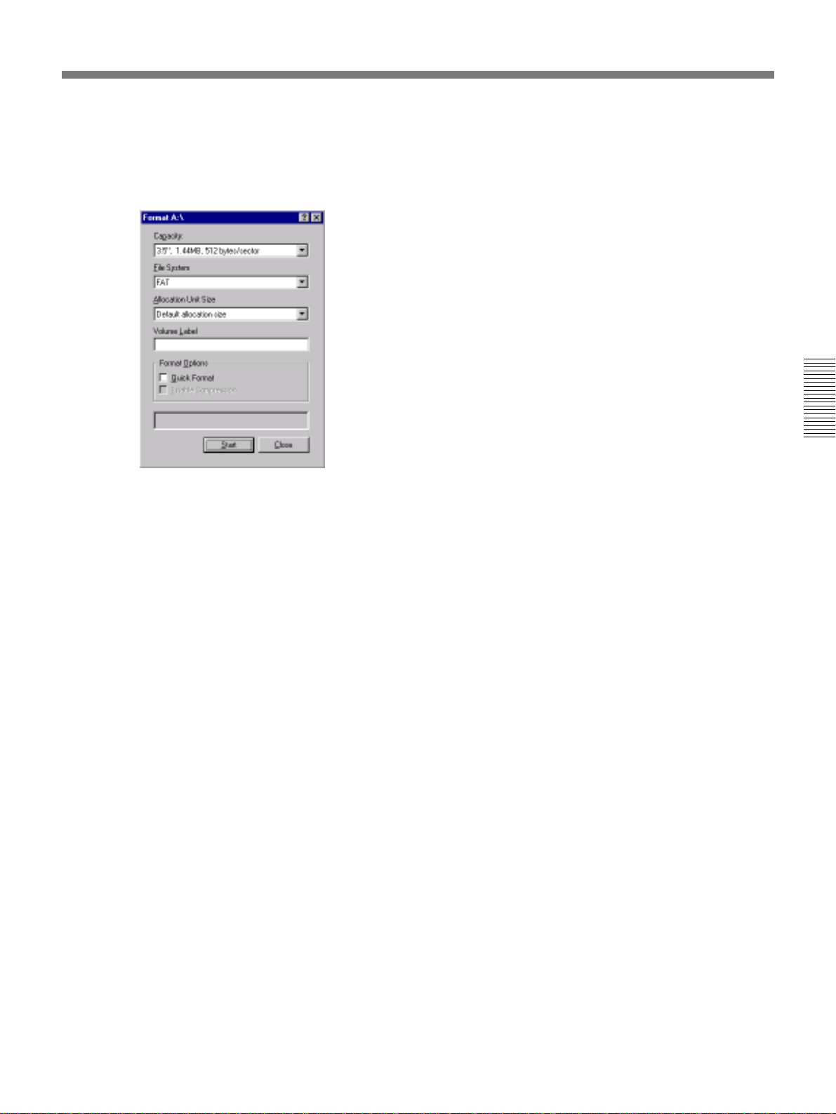
4 Move the pointer to the 3
the right mouse button, and select Format from the
menu that appears.
The Format A: dialog box appears.
1
/2 Floppy (A:) icon, click
5 Select 1.44 MB (2HD) or 720K (2DD) from the
Capacity list and click the Start button.
Chapter 3 Connections and Settings
Disk formatting starts.
6 When the formatting is finished, click the Close
button.
Chapter 3 Connections and Settings 65
Page 66

Using CD-ROM Discs
The software and online manual for this unit are
supplied on a CD-ROM disc. Software upgrades may
also be provided on CD-ROM discs.
This section will explain the basics of handling floppy
disks.
Inserting and removing CD-ROM discs
Inserting CD-ROM discs
Proceed as follows to insert a CD-ROM disc.
1 Press the EJECT button to bring the tray out.
Chapter 3 Connections and Settings
2 Place the CD-ROM disc on the tray with the label
side up.
3 Press the EJECT button to close the tray.
Removing CD-ROM discs
To remove a CD-ROM disc, press the EJECT button
to bring the tray out, lift the disc from the tray, and
press the EJECT button again to close the tray.
If the tray does not come out when you
press the eject button
First shut down the system using the procedure
explained in “Shutting Down the System” (page 26).
Then open the tray as follows.
Label side up
Be careful to place the disc so that it is level on the
tray.
Emergency eject hole
Insert a tool with a long metal tip into the emergency
eject hole, and push in until the tray cover opens
slightly. When the tray cover opens, grasp it and pull
the tray the rest of the way out.
CD-ROM drive names
To read the data from a CD-ROM disc, you must
specify the drive name of the CD-ROM disc drive. The
CD-ROM disc drive of this unit has the drive name
“D:”.
66 Chapter 3 Connections and Settings
Page 67

Connecting System Components
This section provides examples that show how to
connect the components in your editing system.
Connecting VCRs
The VCR connection examples in this section assume
that an ESBK-7045 Disk Unit has been connected to
the EditStation.
Connecting analog VCRs
You can do the following with a system configured as
shown below.
•Do linear editing using materials stored on tape and
VCR playback.
•Copy clips from tape to the disk recorder.
1
2
REF. VIDEO INPUT
VIDEO 1 OUTPUT
2
COMPONENT 2 OUTPUT
2
RECORDER INPUT
B–Y, R–Y, Y/COMP
PLAYER 2
3
RECORDER
UVW-1800/1800P,
PVW-2800/2800P
REMOTE
For more information about connecting a disk unit, see page
71.
•Do non-linear editing using materials stored on the
disk recorder.
•Record the results of the edit on tape as analog
component video signals.
AUDIO INPUT
CH-1, CH-2
(Recorder)
COMPONENT 2
INPUT
32
PROGRAM OUTPUT
B–Y, R–Y, Y/G
AUDIO OUTPUT
CH-1, CH-2
ES-7
B B OUT 1
1 Cable with XLR connectors
(option)
1
2 75 Ω coaxial cable with
BNC connectors (option)
3 9-pin remote control cable
(option)
2
Chapter 3 Connections and Settings
PLAYER 2
INPUT B–Y,
R–Y, Y/COMP
2
MON IN
LINE
OUTPUT 1, 2
REMOTE
COMPONENT 2
OUTPUT
UVW-1800/1800P,
PVW-2800/2800P
(Player 2)
REF. VIDEO INPUT
VCR switch settings
Switch Recorder Player 1, 2
REMOTE/LOCAL REMOTE REMOTE
VIDEO IN Y–R, B —
REF. VIDEO 75 Ω ON OFF
RECORDER
INPUT 1, 2
AUDIO OUTPUT
CH-1, CH-2
PLAYER 1
3
PLAYER 1
INPUT B–Y,
R–Y, Y/COMP
2
PLAYER 1
INPUT 1, 2
1
PLAYER
INPUT 1, 2
2
REF. VIDEO INPUT
1
See the digital Betacam VCR connection example (page 68) for
connecting a control panel.
UVW-1800/1800P,
PVW-2800/2800P
(Player 1)
REMOTE
Chapter 3 Connections and Settings 67
AUDIO OUTPUT
CH-1, CH-2
COMPONENT 2
OUTPUT
Page 68

Connecting System Components
Connecting digital Betacam VCRs
You can do the following with a system configured as
shown below.
•Do linear editing using materials stored on tape and
VCR playback.
•Copy clips from tape to the disk recorder.
1
COMPOSITE VIDEO OUTPUT
1
SERIAL V/A INPUT
1
Chapter 3 Connections and Settings
PLAYER 2
2
DVW-500/500P
SERIAL V/A
OUTPUT
1
SDI INPUT R
•Do non-linear editing using materials stored on the
disk recorder.
•Record the results of the edit on tape as digital
Betacam video signals.
REF. VIDEO INPUT
ESBK-7011
(Recorder)
RECORDER
REMOTE-1 IN
2
ES-7
B B OUT 1
CONTROL PANEL
Control Panel
1
15-pin remote
control cable
(supplied with
control panel)
SDI OUT R (PGM)
MON IN
SDI INPUT P2
REF. VIDEO
INPUT
REMOTE-1
IN
DVW-500/500P (Player 2) DVW-500/500P (Player 1)
SERIAL V/A
OUTPUT
VCR switch settings
Switch Recorder Player 1, 2
REMOTE/LOCAL 1 (9P) 1 (9P)
VIDEO INPUT SELECT SIF —
REF. VIDEO INPUT 75 Ω ON OFF
PLAYER 1
SDI INPUT P1
1
REF. VIDEO
1
1
SERIAL V/A
OUTPUT
1 75 Ω coaxial cable with BNC connectors (option)
2 9-pin remote control cable (option)
INPUT
2
REMOTE-1
IN
68 Chapter 3 Connections and Settings
Page 69
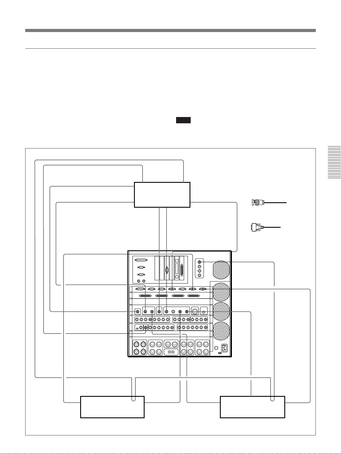
Connecting DSR-series digital VCRs
You can do the following with a system configured as
shown below.
•Do linear editing using VCR playback of materials
stored on tape.
•Copy clips from tape to the disk recorder at 4 times
normal speed.
•Do non-linear editing using materials stored on the
disk recorder.
•Record the results of the edit on tape as serial digital
video signals at 4 times normal speed.
1
1
1
QSDI IN
QSDI OUT
COMPOSITE
OUT
DSR-85/85P (Recorder)
SDI IN
1
In this example, both SDI and QSDI signals are
connected. The roles of the signals are as follows.
SDI signals: Used in linear editing and hybrid
editing.
QSDI signals: Used in non-linear editing and for
uploads and downloads at 4 times normal speed.
Note
When using QSDI input signals, analog video and
audio input signals should also be connected. (See the
next page.)
See the digital Betacam VCR connection
REF. VIDEO
IN
REMOTE
SDI OUT
1
example (page 68) for connecting a
control panel.
1 75 Ω coaxial cable with
BNC connectors (option)
2
2 9-pin remote control
cable (option)
Chapter 3 Connections and Settings
2
REMOTE
PLAYER 2
QSDI INPUT
R/P2
QSDI OUT R
MON IN
DSR-85/85P (Player 2)
SDI OUT
R (PGM)
REF. VIDEO
IN
SDI OUT
SDI INPUT R
QSDI INPUT P1SDI INPUT P2
1
1
RECORDER
B B OUT 1
1
PLAYER 1
SDI INPUT P1
1
1
REF. VIDEO
SDI OUT
QSDI OUT REMOTE
DSR-85/85P (Player 1)
IN
2
Chapter 3 Connections and Settings 69
Page 70

Connecting System Components
Connecting analog signals
Connecting only QSDI signals causes problems such
as not being able to monitor video and audio while
using Video Clip Editor. For this reason, analog video
and audio input signals should also be connected for
monitoring video and audio performance when using
QSDI input signals.
1
1
1
Chapter 3 Connections and Settings
QSDI IN
QSDI OUT
COMPOSITE
OUT
DSR-85/85P (Recorder)
SDI IN
1
SDI OUT
1
REF. VIDEO
IN
1 75 Ω coaxial cable with BNC
connectors (option)
REMOTE
2
2 Cable with XLR connectors
(option)
2
REMOTE
PLAYER 2
QSDI INPUT
R/P2
QSDI OUT R
MON IN
SDI OUT
R (PGM)
REF. VIDEO
IN
SDI OUT
SDI INPUT R
QSDI INPUT P1SDI INPUT P2
1
1
RECORDER
B B OUT 1
1
PLAYER 1
SDI INPUT P1
1
1
REF. VIDEO
SDI OUT
QSDI OUT REMOTE
DSR-85/85P (Player 1)DSR-85/85P (Player 2)
IN
2
70 Chapter 3 Connections and Settings
Page 71

Connecting ESBK-7045 Disk Units
You can do the following with a system configured as
shown below.
•Do non-linear editing using materials stored on the
disk recorder.
•Record up to 4 hours of video on the disk recorder in
high-quality mode.
ES-7
SCSI 1-4
SCSI cable (supplied with
disk unit)
SCSI cable
The ESBK-7041 Disk Recorder Board is required to connect
ESBK-7045 Disk Units.
SCSI 1 IN to SCSI 4 IN
SCSI cable
(supplied with disk unit)
SCSI cable
(supplied with disk unit)
SCSI cable
(supplied with disk unit)
SCSI 1 OUT to
SCSI 4 OUT
SCSI 1 IN to
SCSI 4 IN
SCSI 1 OUT to
SCSI 4 OUT
SCSI 1 IN to
SCSI 4 IN
SCSI 1 OUT to
SCSI 4 OUT
SCSI 1 IN to
SCSI 4 IN
ESBK-7045 Disk Unit
(option)
ESBK-7045 Disk Unit
(option)
ESBK-7045 Disk Unit
(option)
ESBK-7045 Disk Unit
(option)
Chapter 3 Connections and Settings
Chapter 3 Connections and Settings 71
Page 72
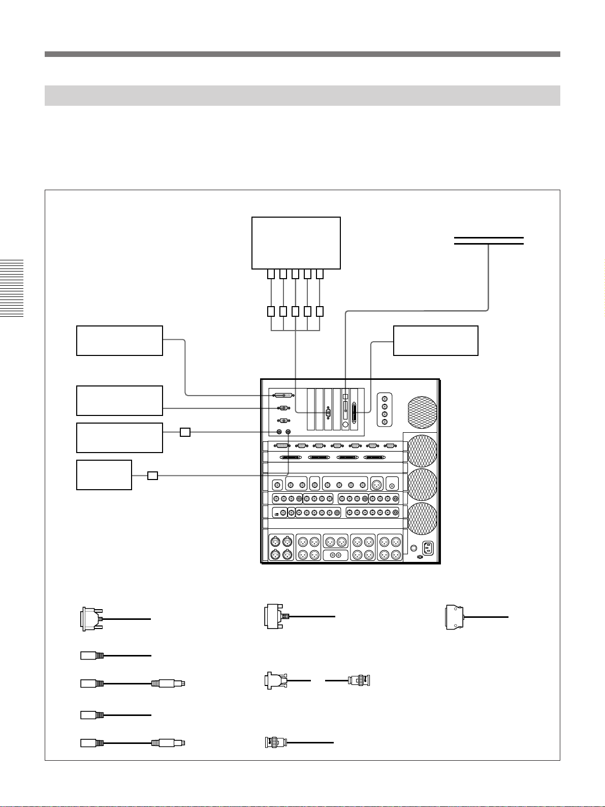
Connecting System Components
Connecting Computer Peripherals
You can do the following with a system configured as
shown below.
•Use a tablet to create graphics.
•Send and receive video and editing data over a
network.
Chapter 3 Connections and Settings
Printer (option)
6
PRINTER
Tablet (option)
1
KEYBOARD
Keyboard (supplied)
32
TABLET
Computer monitor
(option)
8
7
DISPLAY
MONITOR
ETHERNET
•Store editing data on MO disks.
•Print editing data.
SCSI
9
MO drive (option)
Network
!º
Mouse
(supplied)
1 Tablet cable (supplied with tablet)
2 Keyboard cable (1 m, supplied)
3 Keyboard extension cable (4 m, supplied)
4 Mouse cable (1 m, supplied)
5 Mouse extension cable (4 m, supplied)
54
MOUSE
ES-7
6 Printer cable (option)
7 Display monitor multi-cable (D-sub 15-
pin on one end, BNC connector × 5 on
other end, option)
8 BNC extension cable × 5 (Option.
Use 5 cables of same length.)
9 SCSI cable (option; ESBK-7053
recommended)
!º Ethernet connection cable
(Option. Refer to the ESBK7052 Ethernet Option operation
manual for details.)
72 Chapter 3 Connections and Settings
Page 73

Connecting Video/Audio Monitors and Audio Equipment
You can do the following with a system configured as
shown below.
•Record digital audio signals from CDs or DATs to
videotape.
•Monitor audio signals.
Cable with XLR connectors (option)
AES/EBU OUTPUT IEC958 OUTPUT
DAT player
75 Ω coaxial cable
with BNC connectors
(option)
MONITOR
OUTPUT
VIDEO
ES-7
AES/EBU
IN AUX
•Monitor video signals before recording.
•Monitor signals input to the recorder.
IEC958 cable (option)
IEC958
IN AUX
CD player
MONITOR
OUTPUT
Y/G, R–Y/R,
B–Y/B
75 Ω coaxial cable
with BNC connectors
(option)
Chapter 3 Connections and Settings
Composite video
input connector
Preview monitor
MONITOR
OUTPUT
Audio input
connector
Audio amplifier
Stereo cable
(option)
Component
video input
connector
Program monitor
(connect as required)
Chapter 3 Connections and Settings 73
Page 74

Connecting System Components
Connecting an External DME Switcher
You can do the following with a system configured as
shown below.
•Do linear editing using materials stored on tape and
VCR playback.
•Use the DFS-300/300P/500/500P to apply effects and
switch between scenes.
•Record the edit results as analog component video
signals.
Setting the editor selection switch on the DME
switcher
When connecting a DFS-300/300P/500/500P DME
switcher, set the editor selection switch on the DME
switcher as follows.
DFS-300/300P: PVE-500
Chapter 3 Connections and Settings
DFS-500/500P: BVE-900
Types of editing that can be done
The only kind of editing that can be done with a
system configured as shown below is linear editing of
analog video signals. Non-linear editing and editing of
digital signals are not possible.
Signal connections, settings, and limitations
•When you connect an external DME switcher, the
outputs of the MONITOR OUTPUT and PROGRAM
OUTPUT connectors of the ES-7 are as follows.
MONITOR OUTPUT connector: The output is
always the component key fill signal of the
internal titler of the ES-7. Connect to the DSK
VIDEO IN connector or the INPUT-4 connector
of the DFS-300/300P/500/500P.
PROGRAM OUTPUT connector: The output is
always the key source signal of the internal titler
of the ES-7.
•When inputting the key fill signal to both the DSK
VIDEO IN and INPUT-4 connectors, an external
signal distributor is required.
•When you connect an external DME switcher,
connect the output of the PGM OUT connectors of
the DFS-300/300P/500/500P to the AUX INPUT
connectors of the ES-7.
•The correspondence between VCRs and the INPUT 1
to 4 connectors of the DFS-300/300P/500/500P is as
follows.
INPUT-1: PLAYER-1
INPUT-2: PLAYER-2
INPUT-3: AUX
(INPUT-4: Titler key fill)
Set the input signal formats with the input signal
format selection switches on the AD board of the
DFS-300/300P/500/500P. You cannot set the format
from the ES-7 editing software.
•Connect the video monitor that you will use for
previews to the VIDEO OUT connector of the
recorder VCR.
•In the EditStation editing software, select Options
from the Settings menu, and set Preview Mode to PB/
EE.
•When you connect an external DME switcher, you
cannot use the function that superimposes status
information on the output of the MONITOR
OUTPUT VIDEO connector.
•You can operate the DFS-300/300P/500/500P from
the control panel supplied with the DFS-300/300P/
500/500P. However, these operations will not be
reflected in the screens of the EditStation editing
software.
74 Chapter 3 Connections and Settings
Page 75
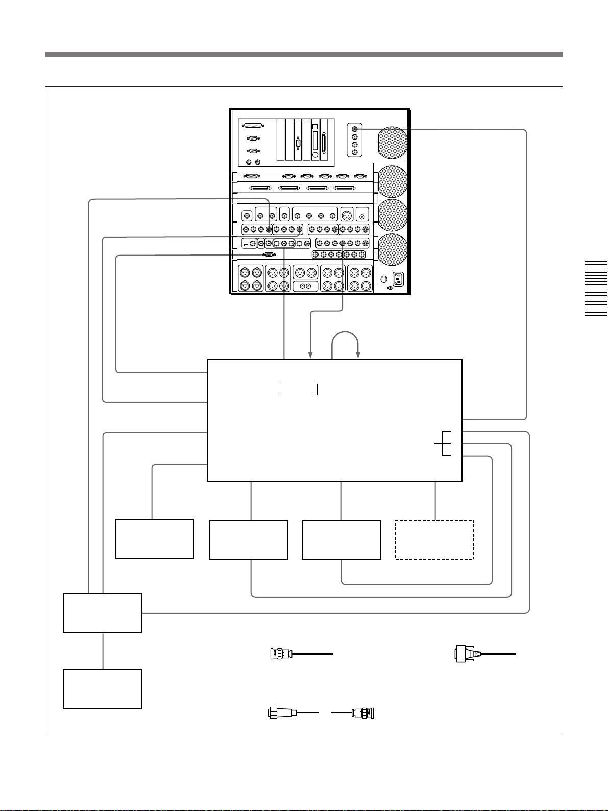
1) The BKDF-504/504P DSK Board must be
installed in the DFS-300/300P/500/500P to
use the DSK signals.
RECORDER INPUT Y/COMP
AUX INPUT Y/G
DFS
MONITOR OUTPUT
1
3
B–Y/B, R–Y/R, Y/G
2
PROGRAM OUTPUT
Y/G
1
1
B B OUT 1
1
Chapter 3 Connections and Settings
1
VIDEO
OUTPUT
UVW-1800/1800P
(Recorder)
2
VIDEO
INPUT
VIDEO
OUTPUT
EDITOR
PGM OUT
(COMPOSITE)
PGM OUT
(COMPONENT)
PGM OUT
Monitor
REF. VIDEO IN
VIDEOINKEY
DFS-300/300P/500/500P
INPUT-1
(COMPONENT)
2
COMPONENT 2
OUTPUT
UVW-1800/1800P
(Player 1)
REF. VIDEO IN
1 75 Ω coaxial cable with BNC
connectors (option)
IN
1)
DSK
INPUT-2
(COMPONENT)
UVW-1800/1800P
(Player 2)
EXT KEY
IN
2
COMPONENT 2
OUTPUT
REF. VIDEO IN
GEN LOCK IN
BLACK
BURST
OUT
INPUT-3
AUX source
3 9-pin remote control cable
1
2
3
(option)
1
11
Preview monitor
2 12-pin to BNC cross cable × 3
(Option. Contact your Sony
dealer.)
Chapter 3 Connections and Settings 75
Page 76

Installing Optional Boards
A variety of expansion boards are available for use
with the ES-7. This section explains how to install the
optional expansion boards.
Warning
•Always power the unit off before installing an
expansion board. Installing boards with the power on
risks fire and electric shock.
•Be careful not to injure your hands or fingers by
cutting them on the edges of expansion boards or
other components.
PC slot number
Chapter 3 Connections and Settings
Motherboard slot
number
1
SY board
65432
Empty
VPR board + DSC
board
PCI PCI PCI/
VGA
ISA
ESBK-7052
BUF board
ISA ISA
When installing an optional board, be sure to install it
in the correct slot, as shown in the figure below.
Installation in the wrong slot can result in damage to
the unit.
1
ESBK-7051
ISA
MPU board
2
RP board
3
I/O board (1 or 2 boards)
4
AD board
5
DA board (+ DAC board)
6
7
FM board or IF board
MY board (+ PU board) or MY board (+ VE board)
8
AU board
9
ESBK-7041
ESBK-7031+ESBK-7032
ESBK-7071
ESBK-7021+ESBK-7022 or
ESBK-7023+ESBK-7024 or
ESBK-7025
Audio connector panel
76 Chapter 3 Connections and Settings
Page 77
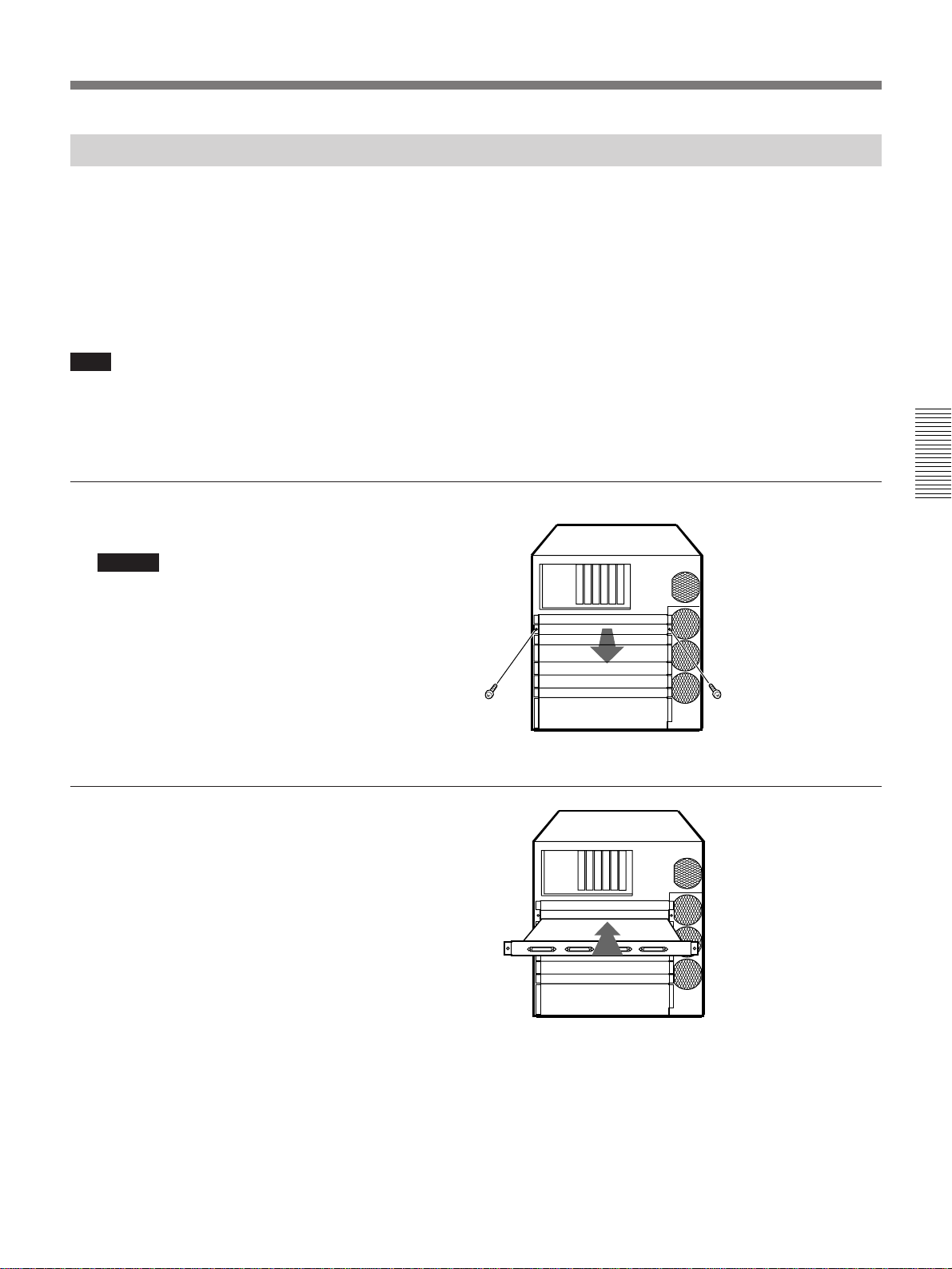
Installing Expansion Boards on the Motherboard
Use the procedure described below to install the
following expansion boards on the motherboard.
•ESBK-7041 Disk Recorder Board
•ESBK-7031 QSDI Interface Board
•ESBK-7021 Basic DME Switcher Board
•ESBK-7023 Advanced DME Switcher Board
•ESBK-7025 External Switcher Interface Board
Note
The following optional boards are daughter boards that
install on another optional board (parent board).
Before installing the parent board on the motherboard,
install the daughter board on the parent board.
1 Remove the two screws and
remove the blank panel.
Caution
Before removing the blank
panel, loosen the screws of the
blank panels or connector
panels in the slots above and
below it, so that these panels
can be moved slightly. If this is
not done, force is required to
remove the blank panel and
injury can result.
If you want to install a daughter board on a parent
board that has already been installed on the
motherboard, remove the parent board from the
motherboard and reinstall it after installing the
daughter board.
•ESBK-7022 3D Effect Board for Basic DME
Switcher (see page 81)
•ESBK-7024 3D Effect Board for Advanced DME
Switcher (see page 82)
•ESBK-7032 SDI Interface Board (see page 83)
•DAC Board for ESBK-7071/7025 (see page 84)
Chapter 3 Connections and Settings
2 Insert the optional board into
the specified slot.
Chapter 3 Connections and Settings 77
Page 78

Installing Optional Boards
3 Firmly push the board all the
way in.
4 Replace the blank panel and
fasten with the screws removed
in step 1.
Chapter 3 Connections and Settings
Notes on installing the DME switcher boards
The ESBK-7021/7023 DME switcher boards are
supplied as 2-board sets.
Before attaching the DME switcher boards, remove the
audio connector panels.
Front
FM board (with connector panel)
DME switcher board
MY board (without connector panel)
Audio board
Side view of ES-7
Back
DME switcher
connector panel
Audio connector
Audio connector
panel
78 Chapter 3 Connections and Settings
Page 79

Installing the ESBK-7021/7023 MY board
1 Remove the two screws from
the audio connector panel.
2 Pull the audio connector panel
and the AU board halfway out.
Note
Place the ES-7 on a desk or
table with enough working
space to avoid applying
excessive force to the cables
connecting the AU board to the
audio connector panel.
3 Remove the cables connecting
the AU board to the audio
connector panel.
4 Install the MY board of ESBK-
7021 or ESBK-7023 in
motherboard slot 8, the slot
located just above the AU
board slot.
AU board
Chapter 3 Connections and Settings
MY board
5 Repeat steps 1 to 3 in reverse
to return the AU board and
audio connector panel to their
original positions.
Chapter 3 Connections and Settings 79
Page 80

Installing Optional Boards
For the positions of the motherboard slots for the following
boards, see page 76.
ESBK-7021 Basic DME Switcher Board or
ESBK-7023 Advanced DME Switcher
Board
Install the two boards of the ESBK-7021/7023 in the
motherboard slots shown below.
Board name Position
FM board Motherboard slot 7
MY board Motherboard slot 8
Installation Notes
•When installing the ESBK-7022/7024 3D Effect
Board together with the DME switcher board, mount
Chapter 3 Connections and Settings
the 3D Effect Board on the MY board of the DME
switcher board before installing the DME switcher
board in the motherboard slot.
For installation of the 3D effect boards, see “Installing the
ESBK-7022 3D Effect Board for Basic DME Switcher”
(page 81), or “Installing the ESBK-7024 3D Effect Board
for Advanced DME Switcher” (page 82).
•The motherboard slot for the MY board is located
behind the audio connector panel. The audio
connector panel must be removed before installing
the board.
For installation of the MY board, see “Installing the ESBK7021/7023 MY board” (page 79).
• The EditStation is shipped from the factory with the
software version installed in it to use the Advanced
DME Switcher. To use the Basic DME Switcher, it
is necessary to carry out software reinstallation.
ESBK-7025 External Switcher Interface
Board
Install the two boards of the ESBK-7025 in the
positions shown below.
Board name Position
DAC board On the video output (DA) board
IF board Motherboard slot 7
For more information about installing the DAC board, see
“Installing the adapter board (DAC) supplied with ESBK7071 ESDraw” (page 84).
Note
If ESDraw and the ESBK-7071 DAC board are
already installed, you do not need to install the DAC
board on the external switcher video output (DA)
board.
ESBK-7041 Disk Recorder Board
Install the two boards of the ESBK-7041 in the
motherboard slots shown below.
Board name Position
MPU board Motherboard slot 2
RP board Motherboard slot 3
ESBK-7031 QSDI Interface Board
Install the ESBK-7031 QSDI Interface Board in
motherboard slot 4.
Note
When installing both the ESBK-7031 and the ESBK7032 SDI Interface Board, mount the SDI Interface
Board on the IO board before installing the ESBK7031 in the motherboard slot.
80 Chapter 3 Connections and Settings
For more information about installing the ESBK-7032, see
“Installing the ESBK-7032 SDI Interface Board” (page 83).
Page 81

Installing Daughter Boards
Installing the ESBK-7022 3D Effect Board for Basic DME Switcher
Proceed as follows to install the ESBK-7022 board on
the MY-74 board of the ESBK-7021 Basic DME
Switcher Board. (The MY-74 board is the board
without a connector panel.)
1 Press the ESBK-7022 board
down onto the MY-74 board
until the two connectors on the
ESBK-7022 are firmly seated
in the two connectors on the
MY-74 board.
2 Using the supplied screws,
fasten the ESBK-7022 board to
the MY-74 board.
Press down firmly until there are no gaps
between the upper and lower connectors when
viewed from direction 1.
1
ESBK-7022
Chapter 3 Connections and Settings
MY-74 board of
ESBK-7021
Yes
No gaps
No
Gaps
3 Remove the connector panel of
the FM-43 board of the ESBK-
7021.
FM-43 board of ESBK-7021
Chapter 3 Connections and Settings 81
Page 82

Installing Optional Boards
4 Insert the two ROMs (IC5 and
IC6) supplied with the ESBK7022 into the sockets of the
FM-43 board of the ESBK7021 board. When inserting,
align the notches on the ROMs
with the notches in the sockets.
After inserting the ROMs,
attach the connector panel of
the FM-43 board in its original
position.
Chapter 3 Connections and Settings
Installing the ESBK-7024 3D Effect Board for Advanced DME Switcher
Notches
FM-43 board of ESBK-7021
IC5
IC6
Proceed as follows to install the ESBK-7024 board on
the MY-75 board of the ESBK-7023 Advanced DME
Switcher Board. (The MY-75 board is the board
without a connector panel.)
1 Press the ESBK-7024 board
down onto the MY-75 board
until the three connectors on
the ESBK-7024 are firmly
seated in the three connectors
on the MY-75 board.
Press down firmly until there are no gaps between the upper
and lower connectors when viewed from direction 1.
2 Using the supplied screws,
fasten the ESBK-7024 board to
the MY-75 board.
1
ESBK-7024
MY-75 board of
ESBK-7023
Yes
No gaps
No
Gaps
82 Chapter 3 Connections and Settings
Page 83
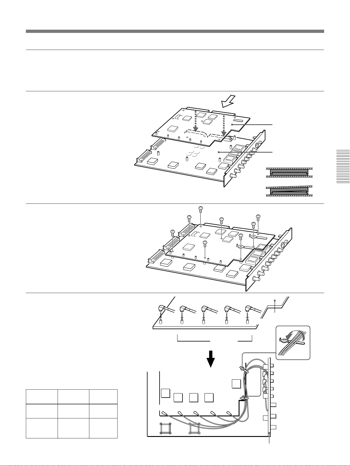
Installing the ESBK-7032 SDI Interface Board
Proceed as follows to install the ESBK-7032 board on
the ESBK-7031 QSDI Interface Board.
1 Press the ESBK-7032 board
down onto the ESBK-7031
board until the two connectors
on the ESBK-7032 are firmly
seated in the two connectors on
the ESBK-7031 board.
2 Using the supplied screws,
fasten the ESBK-7032 board to
the ESBK-7031 board.
Press down firmly until there are no gaps
between the upper and lower connectors
when viewed from direction 1.
1
ESBK-7032
ESBK-7031
Yes
No gaps
Chapter 3 Connections and Settings
No
Gaps
3 Using the coaxial cables
supplied with the ESBK-7032,
connect the SDI input and
output connectors on the
ESBK-7031 connector panel to
the mini BNC connectors on
the ESBK-7032 board.
Connect to the destinations
shown in the illustration. The
connector combinations and
calbe length are as follows.
ESBK-7032 ESBK-7031 Cable
CN31
CN32
CN33
CN34
CN35
CN13
CN14
CN15
CN16
CN17
length
380 mm
580 mm
CN35 CN34 CN33 CN32 CN31
SDI OUT
R(PGM)
CN35 CN34 CN33 CN32 CN31
R AUX P2
SDI INPUT
ESBK-7032
P1
CN13
CN14
CN15
CN16
CN17
ESBK-7031’s connector panel
Chapter 3 Connections and Settings 83
Page 84

Installing Optional Boards
Installing the adapter board (DAC) supplied with ESBK-7071 ESDraw
An adapter board (DAC) is supplied with the ESBK7071 ESDraw drawing software. Install this board on
the video signal output board.
1 Remove the video signal
output board.
Chapter 3 Connections and Settings
2 Press down firmly until the
connectors of the DAC board
are completely seated in the
connectors of the video signal
output board.
3 Using the supplied screws,
fasten the DAC adapter board
to the video signal output
board.
DAC board
Video signal
output board
84 Chapter 3 Connections and Settings
Page 85

Installing Expansion Boards in ISA Slots
Proceed as follows to install the following optional
expansion boards in the ISA slots of the ES-7.
1 Remove the cover of the ES-7
main unit.
2 Remove the slot cover screw
and remove the slot cover.
•ESBK-7051 SCSI Option
•ESBK-7052 Ethernet Option
Chapter 3 Connections and Settings
3 Press the expansion board
down firmly into the specified
slot, and fasten with the screw
removed in step 2.
4 Replace the cover of the ES-7
main unit.
5 Refer to the operation manual
of the expansion board and
install the required driver
software.
Chapter 3 Connections and Settings 85
Page 86

Recommended Connectable Video Equipment
The ES-7 can use status signals sent from video
equipment connected to the remote control connectors
(PLAYER 1, PLAYER 2, RECORDER, AUX) of the
rear panel system control section to automatically
control the operation of the connected equipment using
device constants for the detected device types. The ES7 has built-in device constants for the following video
equipment.
detect the device type of the connected equipment, and
Equipment type Model
S-VHS VCR SVO-5800/5800P, SVP-5600/5600P
Betacam VCR BVW-60/60P/65/65P/70/70P/75/75P, UVW-1600/1600P/1700G/1700GP/1800/1800P,
DVCAM™ VCR DSR-60/60P/80/80P/85/85P
Chapter 3 Connections and Settings
PVW-2600/2600P/2650/2650P/2800/2800P
86 Chapter 3 Connections and Settings
Page 87
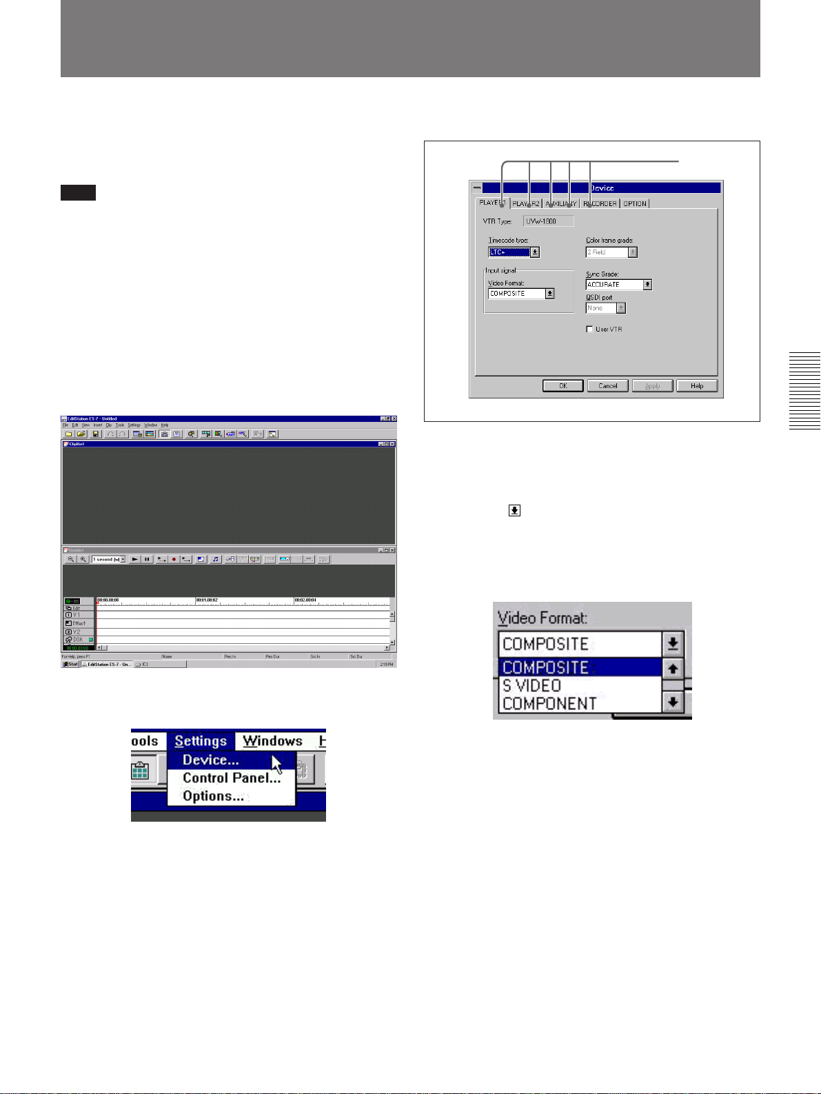
Setting the Video Signal Format
After connecting the VCRs and other peripheral
equipment in your system, use the EditStation Settings
menu to set their video signal formats.
Note
The software must be set up when you use the unit for
the first time.
For more information about setting up the software, see
“Setting Up Windows NT (Using the Unit for the First
Time)” (page 88).
1 Log on and start EditStation using the procedures
explained in “Starting the System” (page 17) and
“Starting EditStation” (page 30).
The EditStation initial screen appears.
The Device dialog box appears.
Tabs
3 Click the tab for the VCR whose signal format you
want to set.
4 Click the button for Video Format.
Chapter 3 Connections and Settings
2 Make the Clip Bin window the active window and
select Device from the Setting menu.
A list of video formats appears. Click the . or >
scroll button to scroll the list and display other
formats.
5 Select the desired video signal format from the list
and click it.
The selected format is highlighted in the list box.
6 Click the OK button.
This completes the selection of the video signal
format. You can begin editing with the selected
format.
For more information about the other items in the
Settings menu, see the online manual.
Chapter 3 Connections and Settings 87
Page 88

Setting Up Windows NT (Using the Unit for the
First Time)
When you use the unit for the first time, Windows NT
must be set up.
Proceed as follows.
1 Power the unit on.
2 Follow the instructions on the computer monitor
and agree to the terms of the licensing agreement.
3 Enter the Product ID.
You can find the Product ID on the Certificate of
Authenticity supplied with the operating system
package.
4 Set the date and time.
Chapter 3 Connections and Settings
For details, see step 3 of “Setting the Date and Time”
on the following page.
5 Follow the instructions on the computer monitor to
complete the setup.
At Network Setup, click the Next button.
When the setup finishes, a message appears to alert
you that all settings have been made.
You will be able to use the unit after it is restarted.
88 Chapter 3 Connections and Settings
Page 89

Setting the Date and Time
Whenever you save data with this unit, the current date
and time are saved together with the data. The correct
date and time are not set when the unit is shipped from
the factory, so be sure to carry out the following
procedure to set the date and time before saving your
data.
1 In the desktop, double click the My Computer icon
to open the My Computer folder, and double click
the Control Panel icon.
The Control Panel window opens.
2 In the Control Panel window, double click the
Date/Time icon.
2)Under the Date & Time tab, set the year, month,
day, hour, minute, second, and AM/PM. You
can select the year and month from the dropdown list or enter them from the keyboard. Set
the day by clicking on the calendar.
Set the hour, minute, second, and AM/PM by
clicking on the item to change and then clicking
the up or down arrow button. You can also enter
the hour, minute, and second from the keyboard.
3)Click the OK button.
4 In the Control Panel window, click the button in
the upper right corner to close the Control Panel
window.
5 In the My Computer window, click the button to
close the My Computer folder window.
Chapter 3 Connections and Settings
The Date/Time Properties dialog box opens.
3 Use the following procedure to set the date and
time.
1)Click Time Zone and set the time zone.
If you do not change the time zone setting, click
the Date & Time tab.
If you do change the time zone setting, click the
Apply button and then click the Date & Time
tab.
Chapter 3 Connections and Settings 89
Page 90
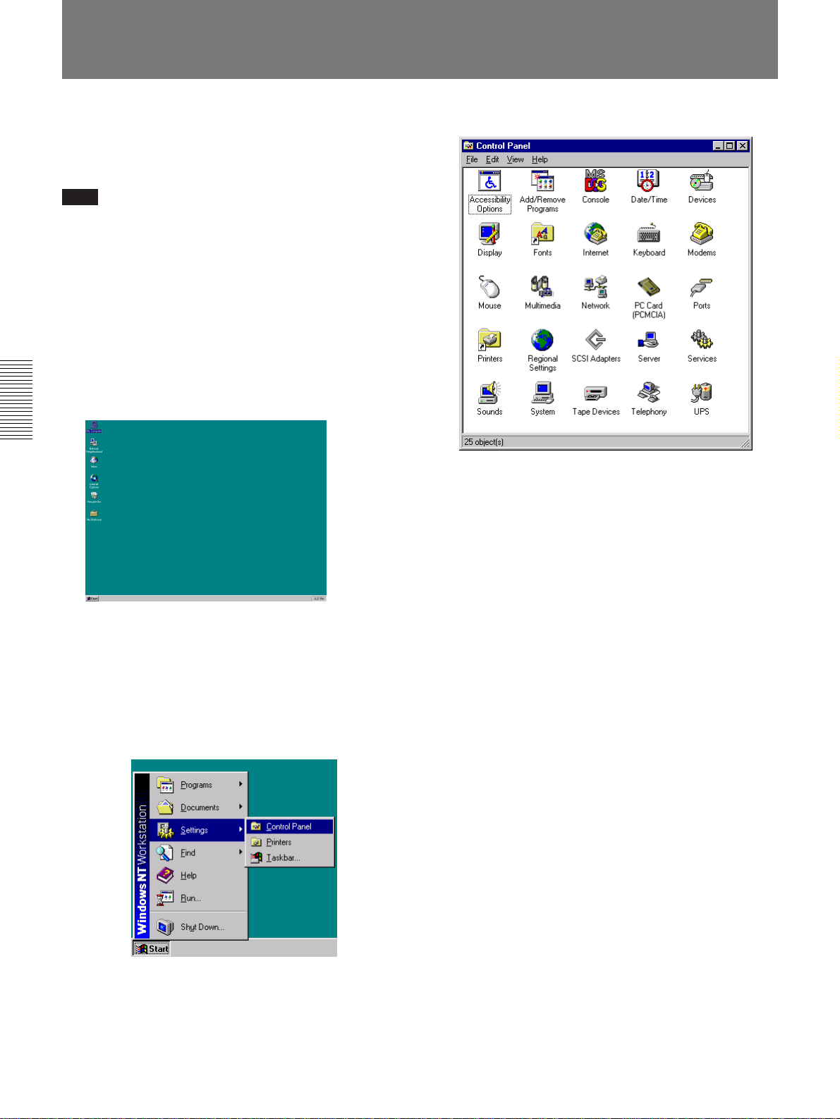
Reinstalling the Software
If the EditStation software fails to operate because of
corrupt program files, reinstall the software using the
following procedure.
Note
Software reinstallation is also necessary to:
• use the ESBK-7021 Basic DME Switcher Board.
• use a French or German version of menu screen
display. (The EditStation is shipped from the factory
with an English version of menu system installed in
it.)
1 Log on using the procedure explained in “Starting
the System” (page 17).
The desktop appears on the screen.
Chapter 3 Connections and Settings
2 Insert the supplied CD-ROM disc.
The Control Panel window opens.
4 Click the Add/Remove Programs icon and carry
out steps 1) to 3) below.
1)Click the Install/Uninstall tab and then click the
Install button.
2)Click the Next button.
3)Check to be sure that D:\SETUP.EXE is
displayed in the command line, and then click
the Finish button.
For more information about inserting CD-ROM discs,
see “Inserting and removing CD-ROM discs” (page
66).
3 Click the Start button in the taskbar, move the
pointer to Settings and click Control Panel.
The setup program starts.
Follow the instructions on the screen to complete
the installation.
5 When the installation of the software is complete,
press the CD-ROM EJECT button to remove the
CD-ROM disc.
90 Chapter 3 Connections and Settings
Page 91

Registering User Names and Passwords
You can register users and passwords to prevent
persons who do not have user names and passwords
from using the system.
The following operations can be performed by users
who belong to the Administrators group or the Power
Users group. Users who log on using the factory
default configuration (user name: “Administrator”;
password: none), belong to the Administrators group.
For more information about user groups, click the Help
menu in the User Manager window.
To register user names and passwords, proceed as
follows.
1 Log on using the procedure explained in “Starting
the System” (page 17).
The desktop appears on the screen.
The User Manager window opens.
3 Select New User from the User menu.
The New User dialog box appears.
4 Enter a user name in the Username field.
User names can be up to 20 characters long. You
can use any combination of uppercase and
lowercase letters and any other characters except
the following:
” / \ [ ] : ; | = , + * ? < >
Chapter 3 Connections and Settings
2 Click the Start button on the taskbar, point to
Programs and Administrative Tools in this order,
and click User Manager.
You cannot assign a user name that has already
been registered.
5 Enter a password in the Password field and the
Confirm Password field.
Passwords can be up to 14 characters long.
Uppercase letters are distinguished from lowercase
letters.
(Continued)
Chapter 3 Connections and Settings 91
Page 92

Registering User Names and Passwords
6 Click the Groups button.
A Group Memberships dialog box like the one
below appears.
Chapter 3 Connections and Settings
7 From the “Not member of” list, select the
Administrators, highlighting it, and click the Add
button.
10Click the OK button of the New User dialog box.
The New User dialog box closes.
The user name that you just registered is displayed
in the Username list of the User Manager window.
11Select Exit from the User menu.
The User Manager window closes.
“Administrators” is added to the “Member of” list.
8 Select Users in the “Member of” list, and then
click the Remove button.
“Users” is removed from the “Member of” list.
9 Click the OK button.
The Group Memberships dialog box closes.
92 Chapter 3 Connections and Settings
Page 93

Executing the Self Diagnostics
The ES-7 has a self-diagnostics function that helps you
to locate the cause of the problem when trouble occurs
in the system.
Technical service will be able to assist you more
rapidly if you report the results of self diagnostics
when requesting repairs for the system.
This section will explain the basics of using the self
diagnostics function.
For more detailed information, refer to the online manual.
Proceed as follows to execute the self diagnostics.
1 Log on using the procedure explained in “Starting
the System” (page 17).
The desktop appears on the screen.
3 Click the System Check button.
The self diagnostics start, and the operation of each
block in the system is checked.
If any errors are discovered by the self diagnostics,
they are recorded in an error log
To check a specific block
In the initial screen of the self diagnostics software,
click the button for the block you want to check.
To view the error log
In the initial screen of the self diagnostics software,
click the Error Log button.
For information about the contents of the error log, refer to
the online manual.
1)
.
Chapter 3 Connections and Settings
2 Click the Start button on the taskbar, point to
Programs and Sony EditStation in this order, and
click SelfDiag.
The initial screen of the self diagnostics software
appears.
..........................................................................................................................................................................................................
1) A file that records the date and time of the self
diagnostics and the error status of each block.
Chapter 3 Connections and Settings 93
Page 94

113
25 14
Pin Assignments
GPI Pin Assignments
To connect external equipment to the GPI connectors
on the rear panel of the ES-7, attach the supplied GPI
connectors to the connection cables.
The GPI pin assignments on the ES-7 side are as
follows.
GPI (PARALLEL) connector
51
96
Pin no. Signal
Chapter 3 Connections and Settings
1 TTL1 OUT
2 RELAY1
3 RETURN1
4 TTL3 OUT
5 GND
6 TTL2 OUT
7 RELAY2
8 RETURN2
9 TTL4 OUT
Computer Connection Section
Pin Assigments
PRINTER connector
Pin no. Signal
1 STROBE
2 DATA1
3 DATA2
4 DATA3
5 DATA4
6 DATA5
7 DATA6
8 DATA7
9 DATA8
COM 1 and COM 2 connectors
Pin no. Signal
10 ACKNLG
11 BUSY
12 PE
13 SLCT
14 AUTOFD
15 ERROR
16 INIT
17 SLCTIN
18 to 25 GND
51
GPI (232) connector
51
96
Pin no. Signal
1 N.C.
2 GPI RXD IN
3 GPI TXD OUT
4 (DTR)
5 SIGNAL GND
6 (DSR)
7 (RTS)
8 (CTS)
9 N.C.
Pins 4 and 6 are connected internally.
Pins 7 and 8 are connected internally.
96
Pin no. Signal
1CD
2RD
3TD
4ER
5SG
6DR
7RS
8CS
9RI
94 Chapter 3 Connections and Settings
Page 95
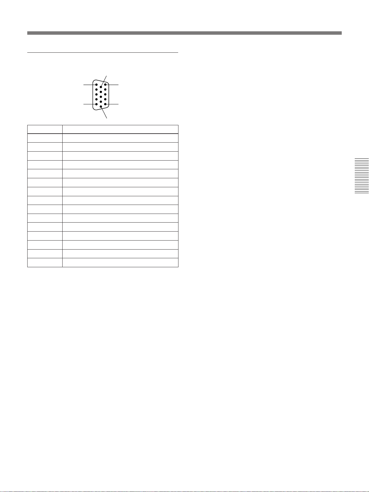
DISPLAY MONITOR connector
6
1
11
Pin no. Signal
1 Red Video
2 Green Video
3 Blue Video
4 Not Used
5 Ground
6 Red Return
7 Green Return
8 Blue Return
9 No Connection
10 Sync Return
11 Not Used
12 Not Used
13 Horizontal Sync
14 Vertical Sync
15 Not Used
5
15
10
Chapter 3 Connections and Settings
Chapter 3 Connections and Settings 95
Page 96

Page 97

Front Panel
Chapter 4 Location and Function of Parts
1 POWER switch
2 CD-ROM access indicator
3 CD-ROM tray cover
4 CD-ROM EJECT button
5 Floppy disk access indicator
6 Floppy disk insertion slot
7 Floppy disk EJECT button
8 HEADPHONES knob
9 Headphones connector
These parts cannot currently be used.
1 POWER switch
Turns the power on and off. Be sure to carry out the
Windows NT shutdown procedure before turning the
power off.
For the Windows NT shutdown procedure, see “Shutting
Down the System” (page 26).
2 CD-ROM access indicator
Normally lights in green, and lights in orange to
indicate that the unit is reading from a CD-ROM disc.
3 CD-ROM tray cover
This is the cover of the tray where CD-ROM discs are
placed.
4 CD-ROM EJECT button
Press this button to open the CD-ROM tray to insert or
remove a disc. To close the tray, push it in.
Chapter 4 Location and Function of Parts
6 Floppy disk insertion slot
Insert 3.5-inch floppy disks here.
7 Floppy disk EJECT button
Press to eject a floppy disk.
Note
Do not press this button while the floppy disk access
indicator is lit.
8 HEADPHONES knob
Controls the volume of the headphones connected to
the headphones connector 9.
9 Headphones connector (stereo phone jack)
Connect headphones. This connector outputs the same
signals as the MONITOR OUTPUT 1/3, 2/4
connectors on the rear panel.
5 Floppy disk access indicator
Lights to indicate that the unit is writing to or reading
from a floppy disk.
Chapter 4 Location and Function of Parts 97
Page 98

Rear Panel
Rear Panel
1 Black burst output section
2 Computer connection section
3 System control section
4 Disk recorder connection section
5 Digital I/O section
6 Video signal I/O section
7 DME switcher section
8 Audio signal I/O section
Chapter 4 Location and Function of Parts
Common Section
1 Cooling fans
2 Breaker
3 AC IN connector
4 Signal ground
terminal
1 Cooling fans
These provide air circulation and prevent temperatures
from rising inside the unit.
Note
When installing the unit, be sure not to block the vents
of the cooling fans.
2 Breaker
Excessive current flows in the internal circuits trip this
breaker, shutting off the power supply. If this occurs,
contact your Sony dealer or Sony service
representative.
3 AC IN connector
Connect the supplied AC power cord.
4 Signal ground terminal
Connect to the ground terminal of a rack or other
equipment.
98 Chapter 4 Location and Function of Parts
Page 99

Connector Sections
1 Black burst output section
B B OUT
1
2
B B OUT 1 to 4 connectors
3
4
2 Computer connection section
1 PRINTER connector
2 COM 1 connector
s COM 2 connector
PRINTER
COM 1
COM 2
B B OUT 1 to 4 (black burst output signal 1 to
4) connectors (BNC type)
Output black burst signals generated by the built-in
sync signal generator.
The same signals are output from all 4 connectors.
Connect these signals to the reference video input
connectors (REF. VIDEO IN, GENLOCK IN, SYNC
IN, etc.) of your source VCRs to synchronize the
source VCRs and this unit.
6 DISPLAY MONITOR connector
DISPLAY
Chapter 4 Location and Function of Parts
KEYBOARD MOUSE
4 KEYBOARD connector
5 MOUSE connector
1 PRINTER connector (D-sub 25-pin)
Connect a printer to print edit data. Connect a printer
equipped with a Centronics compatible interface.
Printer driver software is required to control the
printer. For details refer to the operating instructions of
your printer and the descriptions of the Print Manager
in your Windows NT manual.
2 COM 1 (serial COM port 1) connector (D-sub 9pin)
Connect a tablet for use as a drawing input device.
3 COM 2 (serial COM port 2) connector (D-sub 9pin)
Connect an external computer or modem. Use to
exchange data with external equipment over the RS232C interface.
7 ETHERNET connector
8 SCSI connector
4 KEYBOARD connector (mini DIN 6-pin)
Connect the supplied keyboard.
5 MOUSE connector (mini DIN 6-pin)
Connect the supplied mouse.
6 DISPLAY MONITOR connector (D-sub 15-pin)
Connect an optional computer monitor.
Connect a monitor that supports a vertical refresh rate
of 75 Hz at a resolution of 1024 × 768 pixels.
7 ETHERNET connector (option)
This connector is attached to the ESBK-7052 Ethernet
Option board. Connect an Ethernet cable to exchange
graphics and edit data with other equipment over an
Ethernet network.
Chapter 4 Location and Function of Parts 99
Page 100

Rear Panel
8 SCSI connector (option)
This connector is attached to the ESBK-7051 SCSI
Option board. It allows you to connect an MO drive.
The MO drive is used to store edit data with index
pictures, and to exchange edit data with other
equipment.
3 System control section
1 PLAYER 1 connector
2 PLAYER 2 connector
3 AUX connector
CONTROL PANEL
Chapter 4 Location and Function of Parts
GPI(PARALLEL) GPI(232) RECORDER AUX PLAYER 2 PLAYER 1
1 PLAYER 1 connector (D-sub 9-pin)
Outputs control signals for the player 1 VCR. Connect
to the REMOTE connector of the player 1 VCR.
2 PLAYER 2 connector (D-sub 9-pin)
Outputs control signals for the player 2 VCR. Connect
to the REMOTE connector of the player 2 VCR.
3 AUX (auxiliary) connector (D-sub 9-pin)
Outputs control signals for an auxiliary VCR. Connect
to the REMOTE connector of the VCR connected to
the AUX connector..
4 RECORDER connector (D-sub 9-pin)
Outputs control signals for the recorder VCR. Connect
to the REMOTE connector of the recorder VCR.
4 RECORDER connector
5 GPI (232) connector
6 GPI (PARALLEL) connector
7 CONTROL PANEL connector
5 GPI (232) connector (D-sub 9-pin)
Outputs commands to control external equipment. This
connector complies with the RS-232C standard.
See page 94 for the pin assignments.
6 GPI (PARALLEL) connector (D-sub 9-pin)
Outputs timing pulses to control external equipment.
Connect to the GPI input connector of the external
equipment. There are 4 ports. The signals output by the
4 ports are as follows.
Ports 1, 2: TTL output and relay output
Ports 3, 4: TTL output
See page 94 for the pin assignments.
7 CONTROL PANEL connector (D-sub 15-pin)
Connect the optional ESBK-7011 Control Panel.
100 Chapter 4 Location and Function of Parts
 Loading...