

Sony DynaView SSC-CR441, DynaView SSC-CR481 Operating Instructions Manual

4-299-603-Z2(1)
Color Video Camera
Operating Instructions
Before operating the unit, please read this manual
thoroughly and retain it for future reference.
SSC-CR441/CR481
© 2011 Sony Corporation

Table of Contents
Outline
Features ........................................................................................... 6
Safety Information ............................................................................ 7
Precautions ...................................................................................... 8
Typical CCD Phenomenon ............................................................... 8
Supplied Accessory ......................................................................... 9
Installation Instructions
Location and Function of Part ........................................................ 10
Mount Method ................................................................................ 14
Installing the Camera on a Ceiling ...................................................... 14
Connections and Setup.................................................................. 17
Connecting the Power Source .............................................................. 17
Connecting the I/O Cable .................................................................... 17
Cold Start ....................................................................................... 20
Operation Instructions
Activate OSD Menu........................................................................ 21
Horizontal Pan/Vertical Tilt ............................................................. 21
Scan Function ................................................................................ 22
Auto Scan ............................................................................................. 22
Frame Scanning ................................................................................... 22
Random Scanning ................................................................................ 23
Camera Settings ............................................................................ 24
FOCUS ................................................................................................ 24
AUTO EXPOSURE (AE) .................................................................... 24
ZOOM .................................................................................................. 26
WHITE BALANCE (WB) ................................................................... 27
NOISE REDUCTION ......................................................................... 27
SHARPNESS ....................................................................................... 28
SYNC LOCK ....................................................................................... 29
PRIVACY AREA ................................................................................. 29
Horizontal Pan/Vertical Tilt Setup................................................... 32
2
Table of Contents

SCAN LIMIT STOPS .......................................................................... 32
RECOVER TIME ................................................................................ 32
FREEZE ACTIVITY ........................................................................... 33
Activate TOUR/SCAN ........................................................................ 33
SPEED ................................................................................................. 34
STOP TIME ......................................................................................... 34
AUTO FLIP ......................................................................................... 35
MANUAL SPEED ............................................................................... 35
MANUAL LIMIT STOPS ................................................................... 35
STABILIZER ....................................................................................... 36
CAMERA TITLE ............................................................................. 37
CAMERA TITLE INPUT ................................................................... 37
PRESET SETUP............................................................................ 38
PRESET TOUR ................................................................................... 38
TITLE .................................................................................................. 39
PRESET MOTION .............................................................................. 39
OTHERS ........................................................................................ 41
SCHEDULE ........................................................................................ 41
MOTION DETECTION ...................................................................... 42
SYSTEM ........................................................................................ 43
DATE & TIME .................................................................................... 43
PASSWORD ........................................................................................ 44
ALARM IN .......................................................................................... 44
ALARM OUT ...................................................................................... 45
POSITION AT ALARM ...................................................................... 46
LOAD FACTORY DEFAULT ............................................................. 46
REFRESH DRIVE SYSTEM .............................................................. 47
MIRROR .............................................................................................. 47
Menu Index
Menu Structure............................................................................... 48
Menu Settings List.......................................................................... 51
Preset Commands
Preset Commands ......................................................................... 55
Table of Contents
3

FUNCTION SWITCH Settings
Camera Address Settings .............................................................. 57
Baud rate / Indication / Terminal resistance / Interface Settings .... 66
Specifications
Specifications ................................................................................. 67
Dimensional Drawing ..................................................................... 70
Compatible Communication Protocol Table ................................... 71
4
Table of Contents

Outline
WARNING
To reduce a risk of fire or
electric shock, do not expose
this product to rain or moisture.
For the customers in Europe,
Australia and New Zealand
Outline
WARNING
This is a Class A product. In a domestic
environment, this product may cause radio
interference in which case the user may be
required to take adequate measures.
In the case that interference should occur,
consult your nearest authorized Sony
service facility.
This apparatus shall not be used in the
residential area.
To avoid electrical shock, do
not open the cabinet. Refer
servicing to qualified personnel
only.
The apparatus shall not be exposed to
dripping or splashing and no objects filled
with liquid, such as vases, shall be placed
on the apparatus.
WARNING
This installation should be made by a
qualified service person and should
conform to all local codes.
CAUTION
The rating label is located on the bottom.
For the customers in Europe
The manufacturer of this product is Sony
Corporation, 1-7-1 Konan, Minato-ku,
Tokyo, Japan.
The Authorized Representative for EMC
and product safety is Sony Deutschland
GmbH, Hedelfinger Strasse 61, 70327
Stuttgart, Germany. For any service or
guarantee matters please refer to the
addresses given in separate service or
guarantee documents.
ATTENTION
The electromagnetic fields at specific
frequencies may influence the picture of the
unit.
5

Features
Outline
SSC-CR441/CR481 is a color video
camera, equipped with a 1/4 type CCD,
zoom lens and quick 360° scanning
function. It has following features:
• SSC-CR481: EXview HAD™*CCD
high quality camera is utilized
• High ratio zooming up to:
SSC-CR481: 36x optical zooming
combined with 12x digital zooming can
achieve up to 432x zooming
SSC-CR441: 18x optical zooming
combined with 12x digital zooming can
achieve up to 216x zooming
• SSC-CR481: Day/Night function can be
switched between color/monochrome
mode
• ALARM OUT function
• SSC-CR481: Wide (120x standard)
dynamic range DynaView™
technology (wider than normal for 128
times) is adopted
• PRIVACY ZONE function
• 550-line, high resolution
• 360° high speed rotation, horizontal
speed up to 300°/s
• 360° endless panning and up to 210° tilt
angle
• Line lock sync function by AC power
supply (50Hz)
• 128 preset points
• External control is performed by RS-485
or RS-422
• Settings can be performed using the
screen menu
• RESUME function:
If the preset position 1 had been
registered already, the camera will move
to the preset position 1, but if preset
position 1 would not be registered yet, the
camera will move to the factory set
position.
Otherwise if any action would be running
before power down, camera will resume
the action.
* EXview HAD™ is the trademark of Sony
Corporation.
** DynaView™ is the trademark of Sony Corporation.
**
6
Features

Safety Information
• Read this operating instructions: before
using the product, please carefully read
through the safety information and
operation instructions.
• Keep this operating instructions: safely
store the operating instructions for future
reference.
• Take note of the “Caution” labels: please
follow the “Caution” labels on the
product and operating instructions to
ensure operation safety.
• Follow instructions: when operating the
unit, please follow instructions on the
operating instructions.
• Cleaning: before cleaning the unit, please
first unplug the power.
• Peripheral/accessories: do not place the
unit on an unstable cart, tripod or tabletop
as personal injury and damage to the unit
may occur due to a fall. Please use
officially-certified support, frames, and
accessories included with the product.
Follow the instructions in this operating
instructions during installation to ensure
performance and safety.
• Ventilation: install the unit in a wellventilated place, otherwise the
humidification or vapor may damage
internal parts.
• Power: please observe the labeled
specifications on the unit and power
supply, and use the correct voltage. If
unsure of the actual power requirements,
contact the distributor before connecting
the power.
• Power cable: the power cable must be
properly secured as improper
connections may cause a short circuit,
fire hazards, or serious damage and
hazards.
• Lightning strike: during prolonged
inactivity, please unplug the power cable
and the video cable to avoid damage from
a lightning strike and power surges.
• Foreign objects and fluids: do not insert
any objects into the unit, or spill liquids,
which will likely cause a short-circuit,
especially when the transparent housing
is separated from the main unit to avoid
short circuits.
• Warning: high voltage circuitry is
contained within the unit. Do not
disassemble by yourself to avoid electric
shock. All maintenance operations must
be handled by qualified maintenance
staff.
• Maintenance: if any of the following
occurs, first power off the unit and then
have a qualified technician perform
maintenance:
– Damaged power cable or socket
– Liquid spills or foreign objects in the
unit
– Inoperable unit when proper
instructions are followed
– Dropped unit or damaged shell
– Other anomalies
• Component replacement: replaced
components by the maintenance staff
must be officially-certified parts of
identical specifications. Using
unauthorized components can cause fire
hazards and electric shock.
• Safety inspection: after the unit
maintenance has been completed, the
maintenance staff must perform safety
inspection to ensure proper operation.
Outline
Safety Information
7
Precautions
Outline
• Do not point the camera at the sun, as the
internal CCD component may be
damaged.
• Do not touch the lens surface. Use a
specialized soft cloth to gently wipe off
the lens surface as necessary.
• Avoid direct shooting of intense light
emitting objects, e.g., mercury lamps.
When shooting at strong lights, a vertical
line pattern will show up on the image,
although this is not a camera
malfunction.
• The eclipse phenomenon occurs with the
camera. This is because a sufficient
amount of aperture is not available due to
the CCD size and the lens structure.
However, it has been verified that the
eclipse will not be visible in the case of a
more than 90% effective image.
• Install the unit away from interference
sources and please adjust the video cable
or reinstall if the screen image results in
interference.
• Do not remove the serial number label
from the unit, as this may invalidate the
warranty.
Typical CCD Phenomenon
The following phenomena that may appear
in images are specific to CCD (Charge
Coupled Device) image sensors. They do
not indicate malfunctions.
White flecks
Although the CCD image sensors are
produced with high-precision technologies,
fine white flecks may be generated on the
screen in rare cases, caused by cosmic rays,
etc.
This is related to the principle of CCD
image sensors and is not a malfunction.
The white flecks especially tend to be seen
in the following cases:
–when operating at a high environmental
temperature
–when you have raised the gain (sensitivity)
–when using the slow shutter
Vertical smear
When an extremely bright object, such as a
strong spotlight or flashlight, is being shot,
vertical tails may be produced on the
screen, or the image may be distorted.
Monitor screen
Vertical tails shown on
the image
8
Precautions / Typical CCD Phenomenon
Bright object (e.g.,
strong spotlight, vertical
tails shown on the
image, strong reflected
light, flashlight, the sun)
Aliasing
When fine patterns, stripes, or lines are
shot, they may appear jagged or flicker.

Notices
© 2011 Sony Corporation. Copyright
reserved. No part of this manual or
mentioned software may be reproduced,
translated or simplified to the files that can
be read by the reader, without written
permission of Sony Corporation.
Sony Corporation provides no warranty for
this manual, software or other relevant
information. Therefore, Sony Corporation
declares that this manual, the software or
other information make no implied
commercial warranty; neither can it be used
for any other special purposes. Sony
Corporation shall not be liable for any
incidental, consequential or special
damages for civil infringement, breach of
contract or other reasons which are related
or irrelevant to this manual, the software or
other relevant information.
Sony Corporation reserves the right to
modify the manual and relevant information
at any time without notice.
The software mentioned here can be
assigned independently according to the
specific user licence.
Supplied Accessory
• Ceiling bracket (1)
• Operating instructions (1)
•Screws (2)
• Template (1)
• 24V AC connector (1)
• I/O connector (1)
* Pre-attached to the camera unit.
*
Outline
Supplied Accessory
9
Installation Instructions
Installation Instructions
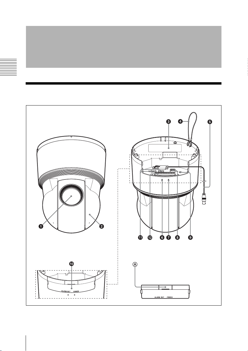
Location and Function of Part
10
Location and Function of Part
Push down the perforated tab
when bundling the cables
from the side of the camera.

1 Lens
2 Camera head
3 Product specifications label
Model names and rated specifications
are labeled.
4 Built-in wire rope
The wire rope is used for fallprevention of the camera.
5 BNC cable
Outputs a composite video signal.
Connect to a composite video input
connector of a video monitor, VCR, etc.
6 ALARM OUT indicator (orange)
The indicator lights up in orange when
the alarm output turns on.
Note
The indicator will not light up when pin
11 in qa FUNCTION SWITCH is set to
OFF. For details, see qa FUNCTION
SWITCH.
7 POWER indicator (green)
The indicator lights up in green when
the power is turned on.
0 Cable cover
Push down the perforated tab A to
bundle the cables from the side of the
camera.
Installation Instructions
Note
The indicator will not light up when pin
12 in qa FUNCTION SWITCH is set to
OFF. For details, see qa FUNCTION
SWITCH.
8 - AC 24 V (power input) terminal
Use the provided 24V AC connector to
connect to the 24 V AC power supply
system.
9 Reset switch
The camera can also be reset to the
factory setting by holding the reset
switch down for 10 seconds with a
needle/paper clip while the power is
turned on.
Location and Function of Part
11

qa FUNCTION SWITCH
Adjust the following settings using the pin 1 to 16.
m
SW Pin No. Function Description
1-8 Camera address switch Set the camera address. For details, see “Camera
Address Settings” on page 57.
9-10 Communication baud rate
Installation Instructions
switch
Set the communication baud rate between the
camera and keypad controller.
Settings for pin 9/10
OFF/OFF: 2400bps, ON/OFF: 4800bps, OFF/
ON: 9600bps, ON/ON: 19200bps
11 ALARM OUT indicator
switch
Turn the indicator on or off.
ON: The indicator lights up in orange while the
alarm function is set to on.
OFF: The indicator does not light up.
12 POWER indicator switch Turn the indicator on or off.
ON: The indicator lights up in green while the
power is turned on.
OFF: The indicator does not light up.
13 Termination switch Set to ON when the unit is connected at the end
of an RS-485 or RS-422 connection. Set to OFF
if it is not connected at the end.
14-16 Communication standard
switch
Set the communication standard between the
camera and keypad controller.
Pin 14
ON: RS-422 communication standard
OFF: RS-485 communication standard
Pin 15-16
ON (both Pin 15 and 16) : RS-485 (half-duplex)
communication standard
OFF (both Pin 15 and 16) : RS-485 (full-duplex)/
RS-422 communication standard
* The information in the table above is also found in “Baud rate / Indication / Terminal resistance /Interface Settings”
on page 66.
Note
In the factory default settings, the camera address switch is set to 0 and both the ALARM
OUT and POWER indicator switches are set to OFF.
12
Location and Function of Part

qs I/O (Input/Output) port
Provides four sensor inputs, one alarm output and one serial communication terminal.
Pin No. Pin name Description
1 ALARM OUT(Normal
Open)
When the alarm function is set to on, this
terminal is connected to the ALARM
COMMON terminal.
2 ALARM COMMON
3 ALARM OUT(Normal
Close)
When the alarm function is set to off, this
terminal is connected to the ALARM
COMMON terminal.
4 Alarm input 1
5 Alarm input 2
6 Alarm input 3
7 Alarm input 4
8 GND
9 Tx+ Serial communication terminal (To receive +)
10 Tx- Serial communication terminal (To receive -)
11 Rx+ Serial communication terminal (To send +)
12 Rx- Serial communication terminal (To send -)
* Connect the Tx+ and Tx- terminals of the controller to the Rx+ and Rx- terminals of the camera unit.
** Connect the Rx+ and Rx- terminals of the controller to the Tx+ and Tx- terminals of the unit when the controller is
equipped with the Rx+ and Rx- terminals.
***Maximum total cable distance for communication over 24-gauge wire is 1,219 m. Sony recommends using shielded
twisted pairs cable that meets or exceeds the basic requirements for the communication standard.
Installation Instructions
Location and Function of Part
13

Mount Method
Notes
• Do not grasp the camera head when
carrying the camera.
Installation Instructions
• Do not turn the camera head manually.
Doing so will likely result in the camera
malfunctioning.
• Turn off the power of the camera before
installing it.
• This unit is a hang-type indoor camera.
Avoid installing the camera at a lower
location, such as floor area, with its head
facing upward.
Install the camera to a horizontal place. If
you have to install the camera to an incline,
make sure the incline is within ±15° to the
horizontal level to ensure the turning
performance of the camera.
Installing the Camera on a Ceiling
Use the supplied ceiling bracket to install
the camera. The ceiling bracket is attached
to the camera unit. Detach the ceiling
bracket before installing.
• If you attach the camera to the ceiling,
check periodically, at least once a year, to
ensure that the connection has not
loosened. If conditions warrant, make
this periodic check more frequently.
Before Installation
• Decide the direction in which the camera
will shoot, before making holes for
wiring and screw holes.
• Push down the perforated tab to bundle
the cables from the side of the camera.
(For details, see “0 Cable cover” in
“Location and Function of Part”.)
Installing Directly on a Ceiling
Using the supplied template, make a hole
for the wiring (ø40 mm). Determine the
location of the three screw holes for
attaching the ceiling bracket.
ø130
3-Screw hole
WARNING
• If you attach the camera in a high location
such as wall or ceiling, etc., entrust the
installation to an experienced contractor
or installer.
• If you install the camera in a high
location, ensure that the ceiling is strong
enough to withstand the weight of the
camera plus mounting brackets and
screws, and then install the camera
securely. If the ceiling is not strong
enough, the camera may fall and cause
serious injury.
• To prevent the camera from falling, make
sure to attach the built-in wire rope.
14
Mount Method
ø40
Cable hole
Unit: mm
Using the Existing Junction
Box
Attach the ceiling bracket to the junction
box. Screws for this operation are not
supplied.
Attach the ceiling bracket in a manner that
the triangular mark faces the front side of
the camera.
Fixing Screws
Required screws (not supplied) vary in
accordance with the location or material of
the installation.
For steel: Fix with M4 screws and nuts.
For wood: Fix with tapping screws
(nominal diameter 4). A material thickness
of 15 mm or more is necessary.
For a concrete wall: Fix with dry bit or plug
bolts.
For a junction box: Fix with screws that
accommodate the screw holes in the
junction box.
WARNING
Use the appropriate screws in accordance
with the condition and material of the
location site. Otherwise, the ceiling unit
may fall and cause serious injury.
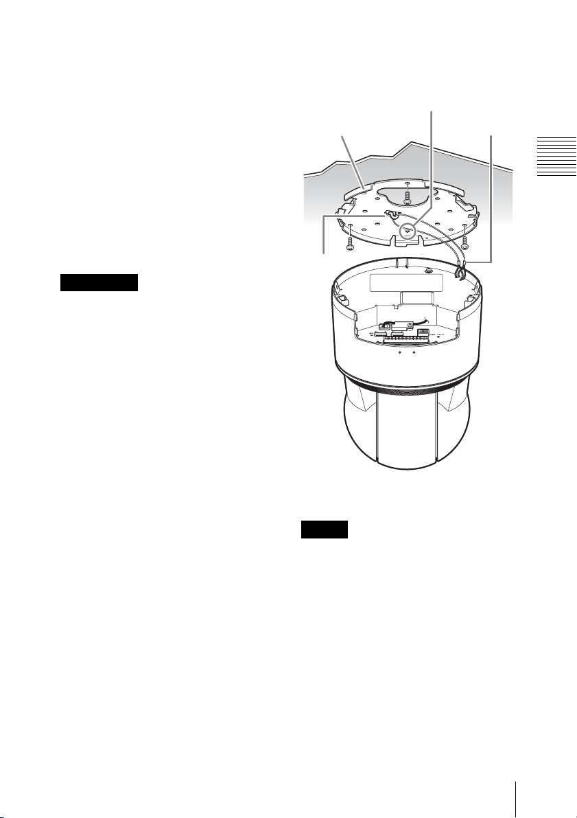
How to Install
1 Put the built-in wire rope on the hook
in the ceiling bracket.
Align the triangular f mark with
the front side of the camera when
using a junction box.
Ceiling bracket
Ceiling
Hook
Built-in wire rope
Installation Instructions
2 Connect the cables.
Note
Although you can connect the cables while
the camera unit is hanging from the ceiling
bracket with the help of the rope, be sure not
to put additional pressure on the unit.
3 Align the triangular f mark on the
camera with the diamond-shaped
mark on the ceiling bracket, and then
attach the camera unit into the bracket.
Mount Method
◊
15
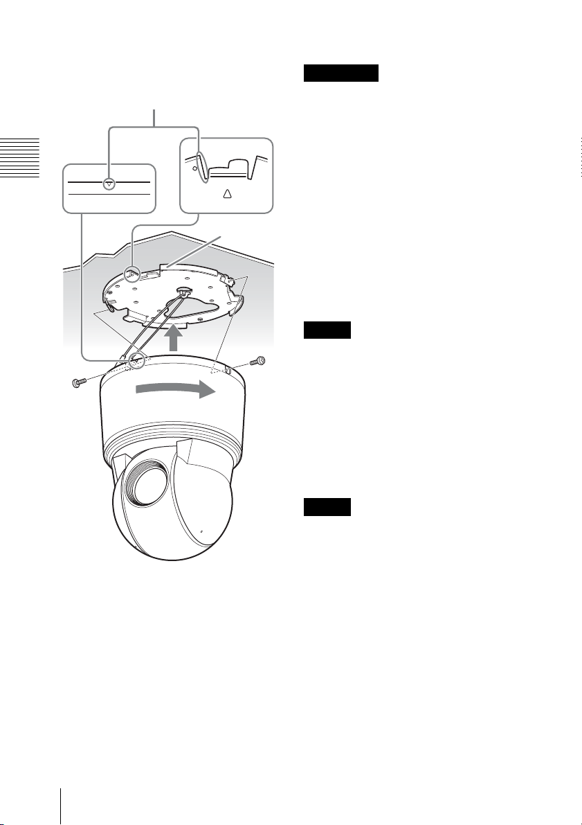
Align the triangular f mark on the
camera with the diamond-shaped ◊ mark
on the ceiling bracket.
CAUTION
Use the supplied screws to install the unit.
Using other screws may cause damage
inside the unit.
How to Remove the Camera
Installation Instructions
1 Loosen and remove the two screws on
both sides of the camera unit.
Ceiling bracket
Ceiling
2 Rotate the camera unit in a
counterclockwise direction, and
remove it from the ceiling bracket.
3 Disconnect the cables.
Screw
(supplied)
4 Rotate the camera unit in a clockwise
direction.
5 Attach the camera unit to the ceiling
bracket by fixing two screws at both
sides of the unit.
6 Attach the cable cover.
Note
Although you can disconnect the cables
while the camera unit is hanging from the
ceiling bracket with the help of the rope, be
sure not to put additional pressure on the
unit.
4 Unhook the built-in wire rope from
the ceiling bracket, and dismount the
camera unit.
Note
Always hold the camera when you
dismount the camera unit. This will prevent
any risk of the camera falling.
16
Mount Method
Connections and Setup
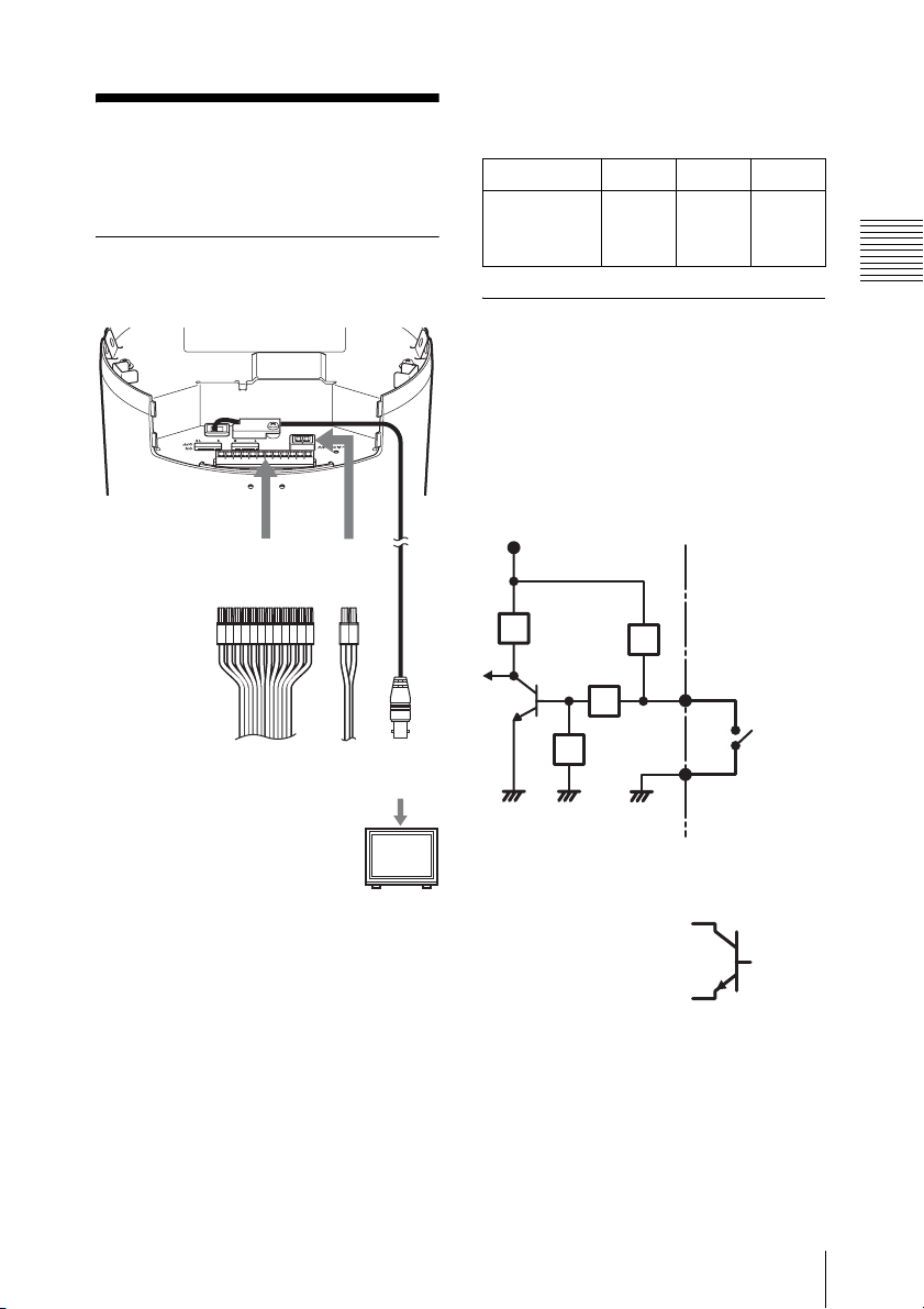
Connecting the Power Source
I/O connector
(supplied)
24 V AC
connector
(supplied)
Recommended Power Cable
24 V AC
Cable(AWG) #24 #22 #20
Maximum
cable length
(m)
11 19 28
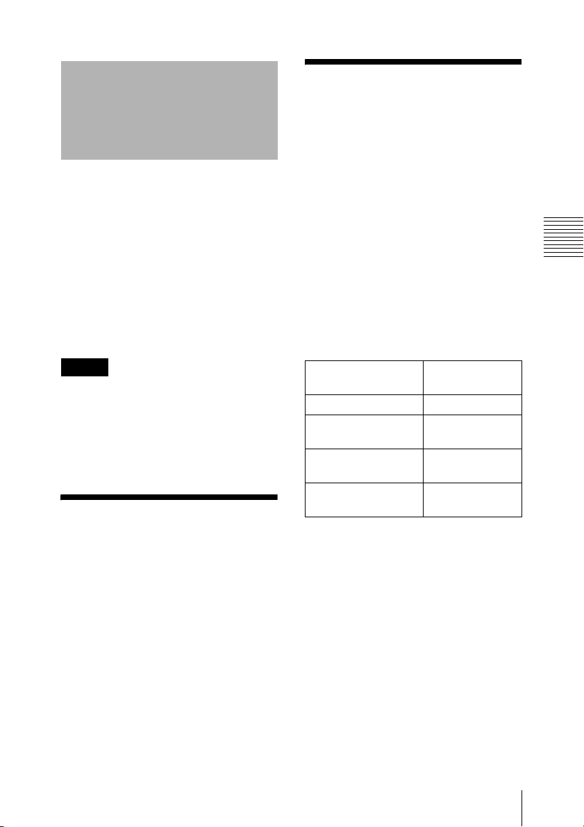
Connecting the I/O Cable
Wiring Diagram for Alarm
Input
Mechanical switch/open collector
output device
Camera inside Outside
3.3 V
10 kohms
Installation Instructions
To I /O
devices
To 24 V
AC pow er
supply
BNC cable
To monitor
Connecting to a 24 V AC
Power Source Supply
Connect the 24 V AC power supply system
to the power input terminal of the camera.
• Use a 24 V AC power source isolated
commercial power supply.
• The usable voltage range is as follows:
24 V AC: 21.6 to 26.4 V
• Use a UL cable (VW-1 style 10368) for
24 V AC connection.
2.2 kohms
10 kohms
10 kohms
GND GND GND
Connections and Setup
4, 5, 6 or 7 pin
(Alarm Input
1, 2, 3 or 4)
Mechanical
switch
8 pin
GND
or
Open collector
output device
17
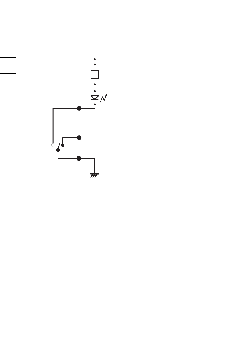
Wiring Diagram for Alarm
Output
OutsideCamera inside
24 V DC
Installation Instructions
Magnet relay
24 V AC,
24 V DC,
1 A or less
1 pin
ALARM OUT
(Normal Open)
2 pin
ALARM
COMMON
R
3 pin
ALARM OUT
(Normal Close)
Circuit
example
GND
18
Connections and Setup
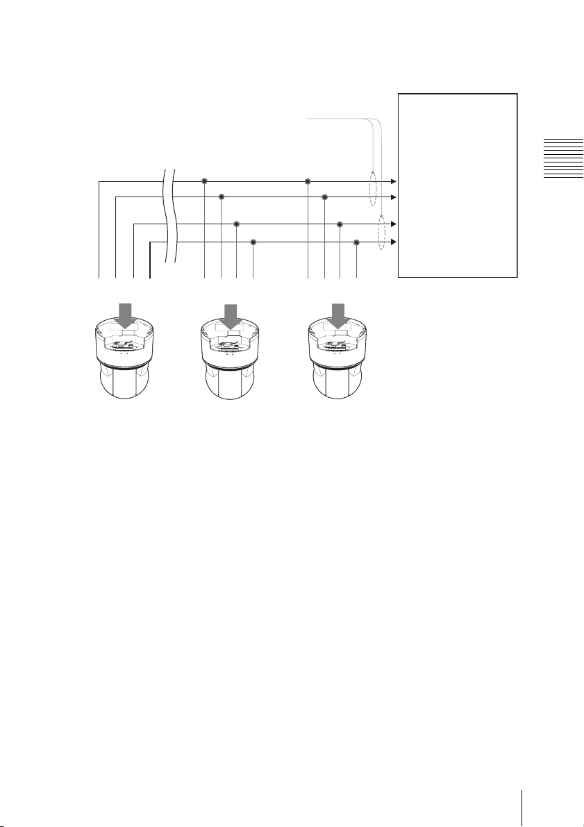
Wiring Diagram for Serial Communication Terminal
Maximum total cable distance for
communication over 24-gauge wire is 1,219 m.
Sony recommends using shielded twisted pairs
cable that meets or exceeds the basic
requirements for the communication standard.
*
*
pin 9
pin 10
pin 11
pin 12
To I/O connector
Set pin 13 to ON. For the
settings on the other pins of
the FUNCTION SWITCH,
see qa FUNCTION
SWITCH in “Location and
Function of Part”.
*
pin 9*pin 10
pin 11
To I/O connector To I/O connector
2nd unitUnit at the end of the wire
Set pin 13 to OFF. For the settings on the
other pins of the FUNCTION SWITCH,
see qa FUNCTION SWITCH in
“Location and Function of Part”.
pin 12
*
pin 9*pin 10
1st unit
pin 11
pin 12
Connections to the
serial communication
terminal in the keypad
controller.
To Rx+ terminal *
To Rx- terminal *
To Tx+ terminal
To Tx- terminal
* NO connection to the I/O
connector pin 9 and 10 of
the camera is required
either when the keypad
controller does not have
Rx+ and Rx- terminals or
when more than one
camera is connected with
the RS-422
communication standard.
Installation Instructions
The number of connectable
cameras
RS-422 communication standard: Up to 10
cameras
RS-485 communication standard: Up to 32
cameras*
* Up to 31 cameras can be connected with RS-485
(half-duplex) communication standard. The number
of connectable cameras may vary depending on the
keypad controllers. For details, refer to the
instruction manual supplied with your keypad
controller.
Connections and Setup
19

Cold Start
Allow enough time for low inner
temperature to reach above 0 degrees
Celsius before turning the camera unit on.
Installation Instructions
Notes
• When the camera is started at below 0
degrees Celsius, it may operate
improperly and cause damage to the unit
due to low inner temperature.
• After it is turned on for more than one
hour and its inner temperature rises, the
camera operates properly under the
environment of –10 degrees Celsius.
20
Cold Start
Operation
Horizontal Pan/
Instructions
Opening message: the startup screen will
show the software version, communication
protocol, machine address, and
transmission baud rate, etc.
Opening message will disappear after a few
seconds. For its re-display, press the
number “75” key+ PRESET key. (See
“Preset Commands” on page 55.)
Wait the operation until disappearance of
the opening message. Otherwise some
delay of process may occur.
Note
After changing a setting on a menu, wait at
least 20 seconds before turning off the
power of the camera.
If the power is turned off immediately, the
new setting may not be stored correctly.
Activate OSD
Vertical Tilt
Manual horizontal pan
Manual horizontal pan must be controlled
through the joystick on the keypad
controller. The rotation speed is adjustable
between 0.1° - 120°/sec by the position of
the joystick, and the maximum manual
horizontal pan speed is up to 120°/sec.
The limitation of maximum pan speed is
enabled by camera setting.
Manual vertical tilt
Manual vertical tilt speed is adjustable
between 0.1° - 60°/sec, and the speed will
be restricted by the manual speed setup of
pan speed.
Horizontal pan range 360° continuous
rotation
Vertical tilt range 210°
Manual vertical tilt
speed
Manual horizontal pan
speed
Preset maximum
rotation speed
0.1° - 90°/s
0.1° - 60°/s
Horizontal: 300°/s
Vertical: 300°/s
Operation Instructions
Menu
The method to activate the OSD menu may
differ depending on the connected keypad
controller. For a keypad controller that is
compatible with Pelco D keypad controller,
press the number keys “95” and then press
and hold the “Preset” key for 3 seconds to
activate the OSD menu. For other special
functions and key combinations, refer to the
table on page 55.
Activate OSD Menu / Horizontal Pan/Vertical Tilt
21
Scan Function
Auto Scan
Auto scanning would be resumed if the
camera had been powered down in AUTO
scan mode, or can be controlled by the
keypad controller (for details, see the table
on page 55).
When the scan range has not been
set
Operation Instructions
The camera will rotate horizontally until a
command from the keypad controller is
received (e.g., horizontal rotate, vertical
rotate, iris, focus, etc).
When the scan range has been set
The camera will rotate horizontally in the
scan range until a command from the
keypad controller is received (e.g.,
horizontal rotate, vertical rotate, iris, focus,
etc). For details on configuration about the
scan range enable, see “Horizontal Pan/
Vertical Tilt Setup” on page 32.
Zoom level
When auto scanning is controlled by the
keypad controller, original zoom level will
be maintained.
Tilt angle
When the keypad controller issues an auto
scanning command, the tilt angle will
remain at the original setting.
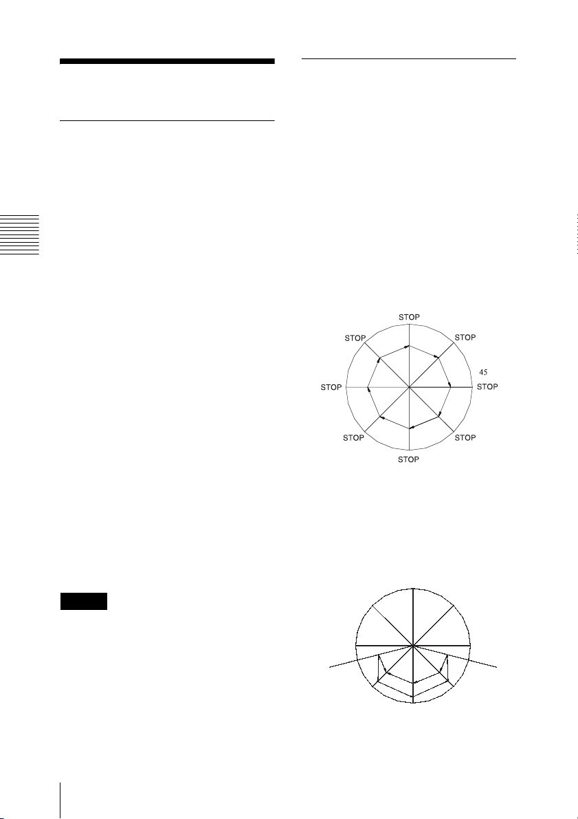
Frame Scanning
Frame scanning would be resumed if the
camera had been powered down in FRAME
scan mode, or can be controlled by the
keypad controller (for details, see the table
on page 55). Configuring the zoom level
and tilt angle is the same as in auto
scanning.
When the scan range has not been
set
The camera will scan at 45° increments
until a command from the keypad controller
is received (e.g., horizontal rotate, vertical
rotate, iris, and focus etc). Refer to the
diagram below.
(stop time)
When the scan range has been set
The camera will scan at 45° increments
within the scan range until a command from
the keypad controller is received (e.g.,
horizontal rotate, vertical rotate, iris, focus,
etc). Refer to the diagram below.
Tips
After a Stop command (“96” + PRESET) or
an Open Menu command (“95” + Set
PRESET) is received, the zoom level and
the tilt angle will be restored if they have
been changed from their defaults.
22
Scan Function
STOP
C
STOP
B
A -->B-->C-->B-->A-->D-->E-->D
STOP
A
45
STOP
E
right limitleft limit
STOP
D
 Loading...