

Sony DXF-801 Operation Manual
3-269-147-02(1)
Electronic Viewfinder
取扱説明書2 ページ JP
Operating Instructions Page 13 GB
Mode d’emploi Page 22 FR
Bedienungsanleitung Seite 32 DE
Printed in Japan
Istruzioni per l’uso Pagina 42 IT
Manual de instrucciones Página 52 ES
CS
お買い上げいただきありがとうございます。
電気製品は、安全のための注意事項を守らないと、
火災や人身事故になることがあり、危険です。
この取扱説明書には、事故を防ぐための重要な注意事項と製品の取
り扱いかたを示してあります。この取扱説明書をよくお読みのうえ、
製品を安全にお使いください。お読みになったあとは、いつでも見
られるところに必ず保管してください。
DXF-801
© 2007 Sony Corporation
日本語
安全のために
ソニー製品は安全に充分配慮して設計されています。し
かし、電気製品は、まちがった使いかたをすると、火災
や感電などにより死亡や大けがなど人身事故につながる
ことがあり、危険です。
事故を防ぐために次のことを必ずお守りください。
安全のための注意事項を守る
4 ページの注意事項をよくお読みください。製品全般の
注意事項が記されています。
定期点検をする
長期間、安全にお使いいただくために、定期点検をする
ことをおすすめします。点検の内容や費用については、
ソニーのサービス担当者または営業担当者にご相談くだ
さい。
故障したら使わない
すぐに、ソニーのサービス担当者または営業担当者にご
連絡ください。
万一、異常が起きたら
• 煙が出たら
• 異常な音、においがしたら
• 内部に水、異物が入ったら
• 製品を落としたり、キャビネットを破損したときは
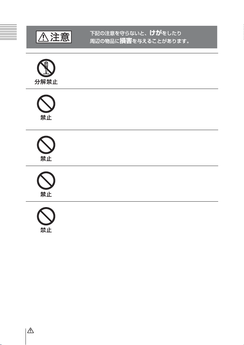
警告表示の意味
取扱説明書および製品で
は、次のような表示をし
ています。表示の内容を
よく理解してから本文を
お読みください。
この表示の注意事項を守ら
ないと、感電やその他の事
故によりけがをしたり周辺
の物品に損害を与えたりす
ることがあります。
注意を促す記号
行為を禁止する記号
m
a 電源を切る。
b 電源コードや接続ケーブルを抜く。
cソニーのサービス担当者または営業担当者に連絡する。
炎が出たら
m
すぐにカメラ / カムコーダーの電源を切り、消火する。
安全のために
2

目次
注意 ................................................................................4
概要 .....................................................................................5
各部の名称と働き................................................................6
カメラ / カムコーダーに取り付ける ...................................8
ビューファインダーを取り付ける................................... 8
取り外すときは................................................................ 9
ビューファインダー画面を調整する ...................................9
視度を調整する................................................................ 9
コントラストと明るさを調整する................................. 10
輪郭を強調する.............................................................. 10
アイピース部のお手入れ ...................................................11
仕様 ...................................................................................11
JP
目次
3
分解しない、改造しない
分解したり、改造したりすると、感電の原因となります。
ビューファインダー内部の調整や点検を行う必要がある場合は、
必ずソニーのサービス担当者にご依頼ください。
内部に水や異物を入れない
水や異物が入ると火災の原因となります。
万一、水や異物が入ったときは、すぐにカメラ / カムコーダーの
電源を切り、接続コードを抜いて、ソニーのサービス担当者また
は営業担当者にご相談ください。
油煙、湯気、湿気、ほこりの多い場所では設置・使用し
ない
上記のような場所で設置・使用すると、火災や感電の原因となり
ます。
ビューファインダーの接眼レンズを太陽に向けて放置し
ない
太陽光が接眼レンズを通してビューファインダー内部に焦点を結
び、火災の原因となることがあります。
太陽や輝度の高い光源にレンズを向けてアイピースを覗
かない
目を痛める原因になります。
注意
4

概要
た、画面やミラーにほこりが付着したと
きは、アイピース部をはね上げてクリー
ニングすることができます。
エレクトロニックビューファインダー
DXF-801 は、アスペクト比 4:3 と 16:9 を
切り換え可能な 1.5 型ビューファイン
ダーです。カラービデオカメラ DXCD50/D55 シリーズや、プロフェッショナ
ルディスクカムコーダー PDW-F330/
F350 シリーズ、デジタルカムコーダー
DSR-400/450WS シリーズに取り付けて
使用します。
DXF-801 には、以下のような特長があり
ます。
アスペクト比 4:3/16:9 切り換
え可能
使用するカメラ / カムコーダーに応じ
て、スキャンサイズを 4:3 または 16:9 に
切り換えることができます。
高性能ブラウン管
• クイックスタートタイプ(電源を入れ
るのとほとんど同時に画像が現れま
す。)
• 高解像度
• 低フレア
その他
大口径で、目を離しても画面が見やすく
なっています。
マーカー表示
カメラ / カムコーダー側で、センター
マーカーやセーフティーゾーンマーカー
などのマーカー表示が ON に設定されて
いる場合、本機のスイッチで、マーカー
表示を ON/OFF できます。
はね上げ可能なアイピース部
アイピース部をはね上げて使うと、目を
離しても画面の中央がぼやけません。ま
概要
5
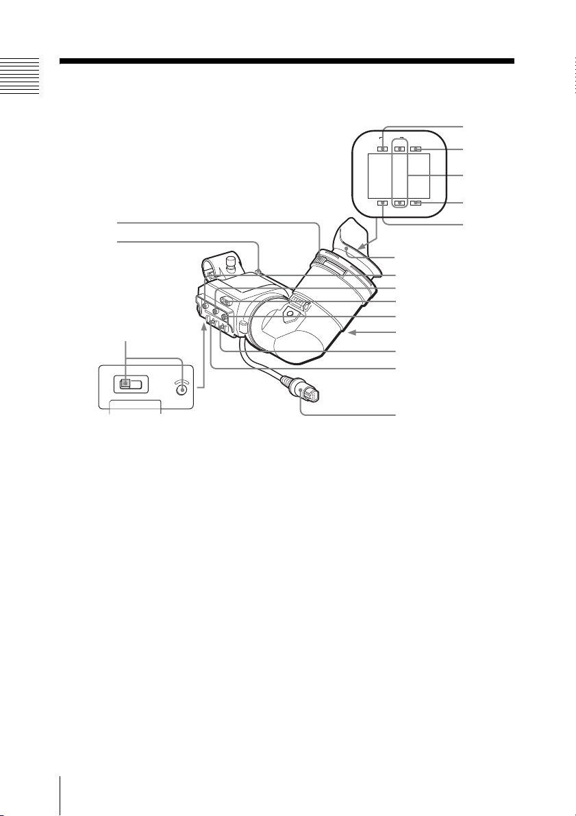
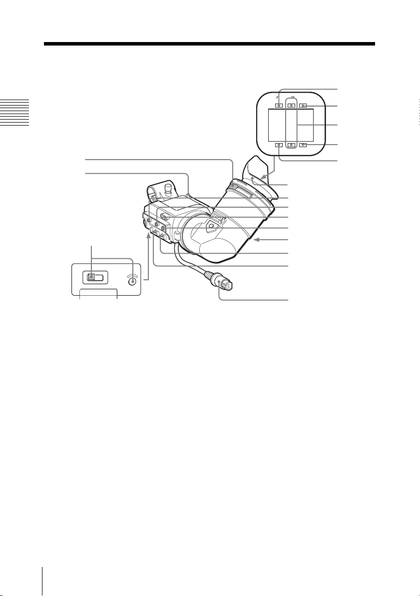
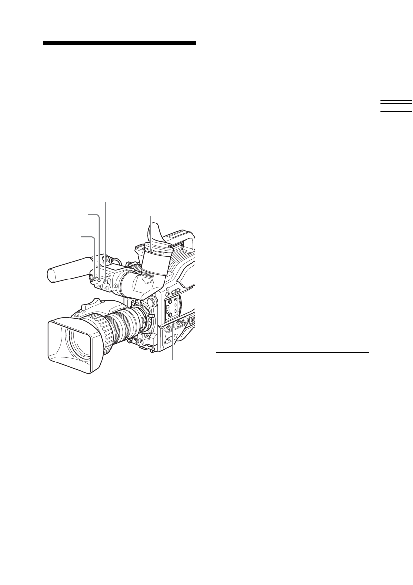
各部の名称と働き
4
q
TALLY
TAKE BATTREC
5
6
1
2
3
HIGH LOW OFF
LIGHT
a 視度調整つまみ
個人差のある視度を調整してビューファ
インダー画面を見やすくしたいとき回し
ます(9 ページ参照)。
b ストッパー
ビューファインダーをカメラ / カムコー
ダーから取り外すとき引き上げます(9
ページ)。
c LIGHT スイッチとライト
レンズを照明するライトとそのコント
ロールスイッチです。
HIGH:明るくする。
LOW:暗くする。
OFF:消灯する。
SHUTTER GAIN UP
7
8
アイカップ
9
0
qa
qs
qd
qf
qg
h
d TAKE/TALLY(テイク / タリー)
ランプ(オレンジ)
カメラ / カムコーダーにカメラコント
ロールユニットを接続しているとき、グ
リーンタリーランプとして働きます。
また、DSR-400/450WS では、インター
バルレックモードにしているとき点滅し
ます。インターバルレックモードで撮影
している間は、点滅速度が速くなりま
す。
e BATT(バッテリー)ランプ(赤)
バッテリーの消耗を知らせます。
各部の名称と働き
6

f REC/TALLY(記録 / タリー)ラン
プ(赤)
• カメラ / カムコーダーまたはレンズの
VTR ボタンを押した後、記録が開始
するまでの間点滅し、記録が開始する
と点灯に変わります。
• カメラコントロールユニット使用時、
本機が取り付けられているカメラ / カ
ムコーダーの映像が選択されると点灯
します。
• カメラ / カムコーダーの異常の発生を
知らせます。
◆ 詳しくは、カメラ / カムコーダーの取扱説
明書を参照してください。
• カメラ / カムコーダーのメニューの設
定により、下側のランプを機能するよ
うにすることもできます。
◆ 詳しくは、カメラ / カムコーダーの取扱説
明書を参照してください。
g GAINUP(ゲイン)ランプ(オレ
ンジ)
カメラ / カムコーダーのゲインが 3dB以
上のとき点灯します。
k タリーランプ
TALLY スイッチ qf が ON のとき、
REC/TALLY ランプ 6 と同様に働きま
す。
l BRIGHT(明るさ)つまみ
ビューファインダー画像の明るさを調整
します(10 ページ参照)。
m 接眼部解除つまみ
ビューファインダー画面を直接見たいと
き、このつまみを押して接眼部をはね上
げます。
n TALLY(タリー)スイッチ
タリーランプ qa を働かせたいとき ON
にします。
o DISPLAY(ディスプレイ)スイッ
チ
ビューファインダー、およびカメラ / カ
ムコーダーの MONITOROUT 端子に接
続されているモニターに表示される文字
情報を消したいときは、このスイッチを
OFF にします。
h SHUTTER(シャッター)ランプ
(赤)
カメラ / カムコーダーの SHUTTER ス
イッチを ON にすると点灯します。
i PEAKING(ピーキング)つまみ
ビューファインダー画像の輪郭強調を調
整します(10 ページ参照)。
j CONTRAST(コントラスト)つ
まみ
ビューファインダー画像のコントラスト
(濃淡)を調整します(10 ページ参照)。
p ビューファインダーコネクター
(20 ピン)
カメラ / カムコーダーの VF 端子と接続
します。
各部の名称と働き
7
カメラ / カムコー ダーに取り付ける
ビューファインダーを取り付けたあと、
接眼レンズを太陽に向けて放置しないで
ください。太陽光が接眼レンズを通して
ビューファインダー内部に焦点を結び、
火災の原因となることがあります。
ご注意
• 必ずカメラ / カムコーダーの電源を
OFF にしてから、ビューファイン
ダーコネクターをカメラ / カムコー
ダーの VF 端子に差し込んでくださ
い。電源が ON の状態でコネクターを
差し込むと、本機が正常に動作しない
ことがあります。
• ビューファインダーコネクターをカメ
ラ / カムコーダーの VF 端子の奥まで
確実に差し込んでください。コネク
ターが確実に接続されていないと、画
像が乱れたり、タリーランプが正常に
点灯しないことがあります。
• 本機は、PDW-F350 のビューファイン
ダーシューに直接取り付けることはで
きません。本機を PDW-F350 に取り付
けるときは、ビューファインダー
シューを交換してください。詳しく
は、お買い上げ店またはソニーのサー
ビス窓口にご相談ください。
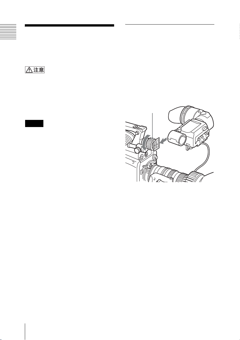
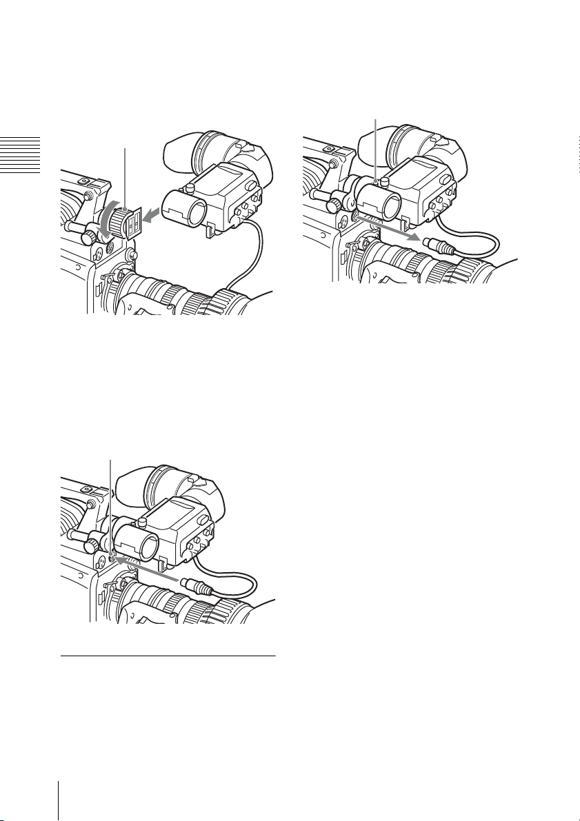
ビューファインダーを取 り付ける
あらかじめ本機からマイクを取り外して
おきます。
1
カメラ / カムコーダーの突起部分に
本機をはめ込み、ビューファイン
ダー左右位置固定リングを締める。
ビューファインダー
左右位置固定リング
2
ビューファインダーコネクターをカ
メラ / カムコーダーの VF端子に差
し込む。
ビューファインダーコネクターは
VF端子の奥に突き当たるまでしっ
かりと差し込んでください。
カメラ / カムコーダーに取り付ける
8
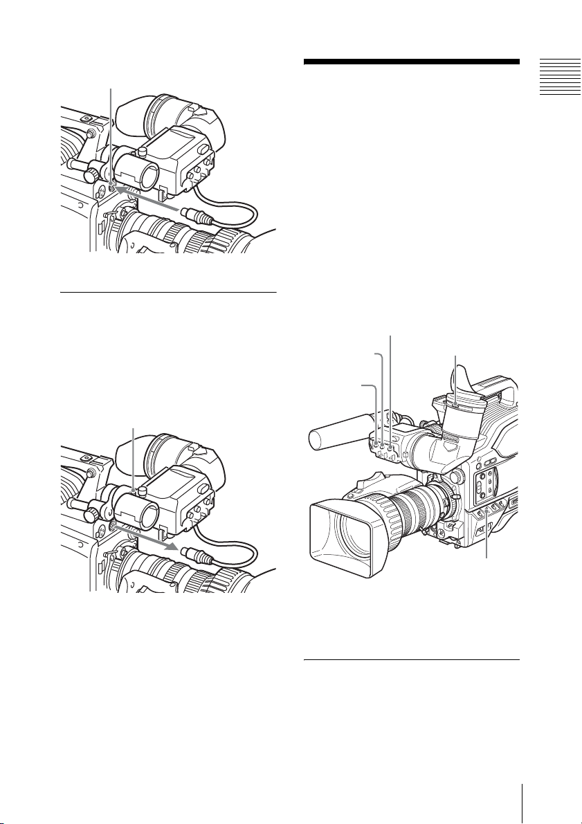
VF 端子
取り外すときは
取り付け操作の手順を逆に実行します。
本機をカメラ / カムコーダーから抜き取
るときは、ストッパーを引き上げてくだ
さい。
ストッパー
ビューファイン ダー画面を調整す る
ビューファインダーの画面を見やすくす
るため、次の調整をします。
なお、ビューファインダーの調整によ
り、ビューファインダー画面の画像を見
やすくすることができますが、カメラ /
カムコーダーの出力信号には影響しませ
ん。
BRIGHT つまみ
CONTRAST
つまみ
PEAKING
つまみ
視度調整つまみ
OUTPUT/DCC
スイッチ
(イラスト:DXC-D55)
(本機には、マイクは付属していません。)
視度を調整する
近視や遠視などの個人差により、一番よ
く見えるファインダーの位置(視度)は
人によって少しずつ違います。ビュー
ビューファインダー画面を調整する
9

ファインダーの画面がはっきり見えるよ
うに、視度を調整してください。
カメラ / カムコーダーのカラーバー信号
を使って調整します。
1
カメラ / カムコーダーの OUTPUT/
DCCスイッチを BARS側にする。
ビューファインダーにカラーバーが
映ります。
2
カラーバーを見ながら、視度調整つ
まみを回して視度を調整する。
1)
調整範囲は− 3D 〜 0D
荷時設定は 0D)。
DXF-801の部品を交換し、視度調整
範囲を− 2D 〜+ 1D または− 0.5D
〜+ 3D に変更することができます。
◆ 詳しくは、お買い上げ店またはソニーの
サービス窓口にお問い合わせください。
3
OUTPUT/DCCスイッチを元の設定
に戻しておく。
です(出
みを回して、 コ ン ト ラ ス ト と明る
さ を調整す る 。
3
OUTPUT/DCC ス イ ッ チを元の設
定に戻し てお く。
輪郭を強調する
PEAKING つまみを回すとビューファイ
ンダー画面の画像の輪郭が強調され、ピ
ントが合わせやすくなります。
1)D:ジオプトリー。光の屈折度を表す単位。
コントラストと明るさを 調整する
カメラ / カムコーダーのカラーバー信号
を使って調整します。
1
カメラ / カムコーダーの OUTPUT/
DCC スイッチを BARS 側にする。
ビューファインダーにカラーバーが
映ります。
2
カラーバーを見ながら、
CONTRASTつまみ、 BRIGHT つま
ビューファインダー画面を調整する
10

アイピース部のお 手入れ
画面とミラーの表面のお手入れ
市販のブロアーを使ってほこりを取り除
いてください。
レンズのお手入れ
市販のレンズクリーナーを使ってクリー
ニングを行なってください。
ご注意
シンナーなどの溶剤は、いっさい使わな
いでください。
仕様
一般
信号形式 EIA 標準/CCIR 標準
走査 2:1 インターレース
525
2:1 インターレース
625
電源 DC12V
消費電力 2.4W
動作温度 −10〜+45℃
保存温度 −20〜+60℃
最大外形寸法 240 × 91 × 196mm
(幅/高さ/奥行
き)
質量 620g
性能
ブラウン管 白黒、1.5 型、アスペ
クト比 16:9/4:3 切
り換え可能
水平解像度 600TV 本(画面中心
部)
付属品
取扱説明書 (1)
保証書 (1)
関連製品
カラービデオカメラ DXC-D50/D55
デジタルカムコーダー DSR-400/450WS
プロフェッショナルディスクカムコー
ダー PDW-F330/F350
1) PDW-F350 に本機を取り付ける場合は、
ビューファインダーシューを交換する必要があ
ります(8 ページ)。
アイピース部のお手入れ/仕様
1)
11

仕様および外観は、改良のため予告なく
変更することがありますが、ご了承くだ
さい。
お使いになる前に、必ず動作確認を
行ってください。故障その他に伴う営
業上の機会損失等は保証期間中および
保証期間経過後にかかわらず、補償は
いたしかねますのでご了承ください。
12
仕様

English
For the customers in the U.S.A.
This equipment has been tested and found
to comply with the limits for a Class A
digital device, pursuant to Part 15 of the
FCC Rules. These limits are designed to
provide reasonable protection against
harmful interference when the equipment is
operated in a commercial environment.
This equipment generates, uses, and can
radiate radio frequency energy and, if not
installed and used in accordance with the
instruction manual, may cause harmful
interference to radio communications.
Operation of this equipment in a residential
area is likely to cause harmful interference
in which case the user will be required to
correct the interference at his own expense.
You are cautioned that any changes or
modifications not expressly approved in
this manual could void your authority to
operate this equipment.
For the customers in Europe
This product with the CE marking complies
with the EMC Directive issued by the
Commission of the European Community.
Compliance with this directive implies
conformity to the following European
standards:
• EN55103-1 :Electromagnetic
Interference (Emission)
• EN55103-2 : Electromagnetic
Susceptibility (Immunity)
This product is intended for use in the
following Electromagnetic Environments:
E1 (residential), E2 (commercial and light
industrial), E3 (urban outdoors), E4
(controlled EMC environment, ex. TV
studio).
guarantee matters please refer to the
addresses given in separate service or
guarantee documents.
GB
The manufacturer of this product is Sony
Corporation, 1-7-1 Konan, Minato-ku,
Tokyo, Japan.
The Authorized Representative for EMC
and product safety is Sony Deutschland
GmbH, Hedelfinger Strasse 61, 70327
Stuttgart, Germany. For any service or
13

Table of Contents
Outline ...................................................................................15
Location and Function of Parts........................................... 16
Attaching the Viewfinder to a Camera/Camcorder ..........17
Attaching the Viewfinder ...............................................17
Detaching the Viewfinder ...............................................18
Adjusting the Viewfinder Screen ........................................19
Adjusting the eyepiece focus ..........................................19
Contrast and brightness adjustment ................................19
Outline emphasis adjustment ..........................................20
Cleaning the Eyepiece ...........................................................20
Specifications .........................................................................21
14
Table of Contents

Outline
The DXF-801 electronic viewfinder is a
1.5-inch viewfinder capable of switching
between 4:3 and 16:9 aspect ratios. It can be
used mounted on a DXC-D50/D55 series
color video camera, PDW-F330/F350
series professional disc camcorder, or DSR400/450WS series digital camcorder.
The DXF-801 has the following features.
Aspect ratio switchable 4:3/
16:9
You can switch the image aspect ratio to 4:3
or 16:9, according to the camera/camcorder
used.
High-Performance CRT
• Quick-start type (The image appears as
soon as the camera/camcorder is turned
on.)
• Enhanced resolution
• Reduced flare
Other
Due to its large diameter, you can see the
screen well at a longer distance.
Marker Indication
When the camera/camcorder is set so that
markers such as a center marker or safety
zone marker are indicated on the viewfinder
screen, marker indication on/off switching
can be controlled on the viewfinder.
Hinging eyepiece
By hinging up the eyepiece, you can move
your eye away and use the viewfinder
without the center being blurred. If dust
accumulates on the screen or mirror, hinge
up the eyepiece and carry out cleaning.
Outline
15
Location and Function of Parts
4
TALLY
TAKE BATTREC
5
6
1
2
3
HIGH LOW OFF
LIGHT
a Eyepiece focusing knob
Turn this to adjust the viewfinder focus to
match your eyesight. (See page 19.)
b Stopper
Lift up when detaching the viewfinder from
the camera/camcorder. (See page 18.)
c LIGHT switch and light
The light illuminates the lens, and the
switch controls the light as follows.
HIGH/LOW: Turn the light on and control
the brightness.
OFF: Turns the light off.
d TAKE/TALLY indicator (orange)
This functions as a green tally lamp when a
camera control unit is connected with the
camera/camcorder.
With the DSR-400/450WS, this indicator
flashes when the camcorder is set to
SHUTTER GAIN UP
7
8
Eyecup
9
0
qa
qs
qd
qf
qg
qh
Interval Rec mode. During recording in
Interval Rec mode, it flashes at high-speed.
e BATT (battery) indicator (red)
This lights when the battery capacity is low.
f REC/TALLY (recording/tally)
indicators (red)
• This flashes from the time when you
press the VTR button on the lens or
camera/camcorder until recording starts,
then stays lit during recording.
• When using a camera control unit, this
lights when the video from the camera/
camcorder to which the viewfinder is
attached is selected.
• This indicates a fault of the camera/
camcorder.
For details, see the operating instructions for the
camera/camcorder.
Location and Function of Parts
16

• The lower indicator can be enabled by the
menu settings of the camera/camcorder.
For details, see the operating instructions for the
camera/camcorder.
Attaching the
Viewfinder to a
g GAIN UP indicator (orange)
This lights when the gain of the camera/
camcorder is 3 dB or more.
h SHUTTER indicator (red)
This lights when the SHUTTER switch of
the camera/camcorder is set to ON.
i PEAKING control
This adjusts the outline intensity of the
viewfinder image. (See page 20.)
j CONTRAST control
This adjusts the contrast of the viewfinder
image. (See page 19.)
k Tally lamp
When the TALLY switch qf is set to ON,
this operates in the same way as the REC/
TALLY indicators 6.
l BRIGHT (brightness) control
This adjusts the brightness of the
viewfinder image. (See page 19.)
m Eyepiece release catch
To view the viewfinder screen directly,
press this catch, and hinge up the eyepiece.
n TALLY switch
Set this switch to ON to use the tally lamp
qa.
o DISPLAY switch
Set this switch to OFF when you want to
hide the character data from the viewfinder
and the monitor of the camera/camcorder
connected to the MONITOR OUT
connector.
Camera/
Camcorder
Notes
• When the viewfinder is attached, do not
leave the camera (or the camcorder) with
the eyepiece facing the sun. Direct
sunlight can enter through the eyepiece,
be focused in the viewfinder and cause
fire.
• Be sure to power off the camera/
camcorder before plugging the
viewfinder connector into the VF
connector on the camera/camcorder. If
the connector is plugged in while the
power is on, the viewfinder may not
operate correctly.
• Make sure that the viewfinder connector
is pushed fully into the VF connector on
the camera/camcorder. If the connector is
not firmly connected, the image may
break up, or the tally lamp may not
operate properly.
• The DXF-801 cannot be directly attached
to the viewfinder shoe of the PDW-F350.
Replace the shoe to attach the DXF-801
to the PDW-F350. For details, please
contact your Sony dealer or a Sony
service representative.
Attaching the Viewfinder
First disconnect the microphone from the
viewfinder.
p Viewfinder connector (20-pin)
Connect this to the VF connector of the
camera/camcorder.
1 Slide the viewfinder onto the
projection on the camera/camcorder,
Attaching the Viewfinder to a Camera/Camcorder
17
and tighten the viewfinder left-to-right
position fixing ring.
viewfinder from the camera/camcorder,
pull up the stopper.
Viewfinder left-to-right
position fixing ring
2 Plug the viewfinder connector into the
VF connector of the camera/
camcorder.
Push the viewfinder connector firmly,
and fully into the VF connector.
VF connector
Stopper
Detaching the Viewfinder
To detach the viewfinder from the camera/
camcorder, conduct the attachment
procedure in reverse. When removing the
Attaching the Viewfinder to a Camera/Camcorder
18
Adjusting the Viewfinder Screen
To improve the visibility of the viewfinder
screen, carry out the following adjustments.
Although these adjustments may make the
viewfinder image clearer, they have no
effect on the output video signal from the
camera/camcorder.
Carry out the adjustment of the eyepiece
focus with the color bars of the camera/
camcorder displayed.
1 Set the OUTPUT/DCC switch of the
camera/camcorder to the BARS
position.
The color bars appear in the
viewfinder.
2 Watching the color bars, turn the
eyepiece focusing knob to adjust the
eyepiece focus.
BRIGHT control
CONTRAST
control
PEAKING
control
(Illustration: DXC-D55)
(Microphone is not supplied with the
viewfinder.)
Eyepiece
focusing knob
OUTPUT/DCC switch
Adjusting the eyepiece focus
Depending on the eyesight of the camera
operator —whether longsighted or
shortsighted — the optimal position of the
viewfinder image varies. Adjust the
eyepiece focus to get the clearest
viewfinder image for your eyesight.
The adjustment range is from –3 to 0
1)
diopters
diopters).
Using an optional part allows you to
modify the adjustment range to –2 to
+1 diopters or –0.5 to +3 diopters.
For details, consult your Sony dealer or a Sony
service representative.
(default when shipped is 0
3 Return the OUTPUT/DCC switch to
its original position.
1) Diopter: A unit to indicate the degree of
convergence or divergence of a bundle of rays.
Contrast and brightness adjustment
Carry out these adjustments with the color
bars of the camera/camcorder displayed.
1 Set the OUTPUT/DCC switch of the
camera/camcorder to the BARS
position.
The color bars appear in the
viewfinder.
2 Watching the color bars, turn the
CONTRAST and BRIGHT controls to
adjust the contrast and brightness.
Adjusting the Viewfinder Screen
19

3 Return the OUTPUT/DCC switch to
its original position.
Cleaning the
Outline emphasis adjustment
Turning the PEAKING control changes the
degree of outline emphasis in the
viewfinder image, to make focusing easier.
Eyepiece
To clean the screen or the mirror
Use a commercially available dust blower.
To clean the lens
Use a commercially available lens cleaner.
Note
Do not use organic solvents such as
thinners.
Cleaning the Eyepiece
20

Specifications
General
Signal format
EIA compliant / CCIR compliant
Scan 2:1 Interlaced 525
2:1 Interlaced 625
Power requirements
12 V DC
Power consumption
2.4 W
Operating temperature
–10°C to +45°C (14°F to +113°F)
Storage temperature
–20°C to +60°C (–4°F to +140°F)
External dimensions
240 × 91 × 196 mm (9
73/4 inches) (w/h/d)
Mass 620 g (1 lb 5 oz)
Performance
CRT 1.5-inch monochrome, aspect ratio
switchable 16:9/4:3
Horizontal resolution
600 TV lines (at center)
1
/2 × 35/8 ×
Design and specifications are subject to
change without notice.
Note
Always verify that the unit is operating
properly before use. SONY WILL NOT
BE LIABLE FOR DAMAGES OF ANY
KIND INCLUDING, BUT NOT
LIMITED TO, COMPENSATION OR
REIMBURSEMENT ON ACCOUNT OF
THE LOSS OF PRESENT OR
PROSPECTIVE PROFITS DUE TO
FAILURE OF THIS UNIT, EITHER
DURING THE WARRANTY PERIOD
OR AFTER EXPIRATION OF THE
WARRANTY, OR FOR ANY OTHER
REASON WHATSOEVER.
Accessories
Operating Instructions (1)
Warranty Booklet (1)
Related Products
Color Video Camera DXC-D50/D55
Digital Camcorder DSR-400/450WS
Professional Disc Camcorder PDW-F330/
1) To attach the DXF-801 to the PDW-F350, it is
1)
F350
necessary to replace the viewfinder shoe (page
17).
Specifications
21

Français
Pour les clients européens
Ce produit portant la marque CE est
conforme à la Directive sur la compatibilité
électromagnétique (EMC) émise par la
Commission de la Communauté
européenne.
La conformité à cette directive implique la
conformité aux normes européennes
suivantes :
• EN55103-1 : Interférences
électromagnétiques (émission)
• EN55103-2 : Sensibilité
électromagnétique (immunité)
Ce produit est prévu pour être utilisé dans
les environnements électromagnétiques
suivants : E1 (résidentiel), E2 (commercial
et industrie légère), E3 (urbain extérieur) et
E4 (environnement EMC contrôlé, ex.
studio de télévision).
Le fabricant de ce produit est Sony
Corporation, 1-7-1 Konan, Minato-ku,
Tokyo, Japon.
Le représentant autorisé pour EMC et la
sécurité des produits est Sony Deutschland
GmbH, Hedelfinger Strasse 61, 70327
Stuttgart, Allemagne. Pour toute question
concernant le service ou la garantie,
veuillez consulter les adresses indiquées
dans les documents de service ou de
garantie séparés.
22
 Loading...