

Sony DXC-D30WS, DXC-D30WSP User Manual

DIGITAL VIDEO CAMERA
DXC-D30WS
DXC-D30WSP
SERVICE MANUAL
Vol. 1 (1st Edition)
Power HAD WS

CAUTION
ADVARSEL
Danger of explosion if battery is incorrectly
replaced.
Replace only with the same or equivalent type
recommended by the manufacturer.
Dispose of used batteries according to the
manufacturer’s instructions.
Vorsicht!
Explosionsgefahr bei unsachgemäßem
Austausch der Batterie.
Ersatz nur durch denselben oder einen vom
Hersteller empfohlenen ähnlichen Typ.
Entsorgung gebrauchter Batterien nach Angaben
des Herstellers.
ATTENTION
Il y a danger d’explosion s’il y a remplacement
incorrect de la batterie.
Lithiumbatteri - Eksplosjonsfare.
Ved utskifting benyttes kun batteri som
anbefalt av apparatfabrikanten.
Brukt batteri returneres
apparatleverandøren.
VARNING
Explosionsfara vid felaktigt batteribyte.
Använd samma batterityp eller en likvärdig typ
som rekommenderas av apparattillverkaren.
Kassera använt batteri enligt gällande
föreskrifter.
VAROITUS
Paristo voi räjähtää jos se on virheellisesti asennettu.
Vaihda paristo ainoastaan laitevalmistajan
suosittelemaan tyyppiin.
Hävitä käytetty paristo valmistajan ohjeiden
mukaisesti.
Remplacer uniquement avec une batterie du
même type ou d’un type équivalent recommandé
par le constructeur.
Mettre au rebut les batteries usagées
conformément aux instructions du fabricant.
ADVARSEL!
Lithiumbatteri-Eksplosionsfare ved fejlagtig
håndtering.
Udskiftning må kun ske med batteri
af samme fabrikat og type.
Levér det brugte batteri tilbage til leverandøren.

MANUAL STRUCTURE
Introducing this manual
Related manuals
This manual is the Service Manual Vol. 1 of the DIGITAL VIDEO CAMERA DXCD30WS and DXC-D30WSP.
This manual contains the operation manual related to the operations of this equipment,
the replacement of the parts and adjustments.
In addition to this Service Manual Vol. 1, the following manuals are provided.
• Service Manual Vol. 2
Part No. 9-977-326-21
Contains block diagrams, board layouts, schematic diagrams, semiconductor pin
assingments and parts lists.
• Service Manual DXF-701/701CE/701WS/701WSCE
Part No. 9-977-265-02
See the DXF-701/701CE/701WS/701WSCE service manual available separately.
• Service Manual VCT-U14
Part No. 9-977-221-01
See the VCT-U14 service manual available separately.
• Service Manual VCL-918BY
Part No. 9-977-329-01
See the VCL-918BY service manual available separately.
DXC-D30WS/P(E)/V1
1

TABLE OF CONTENTS
1. OPERATING INSTRUCTIONS
2. SERVICE INFORMATION
2-1. BOARD LAYOUT................................................ 2-1
2-2. REMOVAL OF CABINET................................... 2-1
2-2-1. Removal of Side Plate ................................... 2-1
2-2-2. Cautions on Disassembly/Assembly of
Top Chassis ................................................... 2-2
2-3. REPLACEMENT OF MAIN PARTS................... 2-2
2-3-1. Replacement of CCD Unit............................. 2-2
2-4. CONNECTORS AND CABLES .......................... 2-4
2-4-1. Connector Input/Output Signals .................... 2-4
2-4-2. Connection Connector ................................... 2-8
2-5. HOW TO HANDLE OF AT-125 BOARD ........... 2-8
2-5-1. How to Attach of the Extention Board
EX-591 .......................................................... 2-8
2-5-2. Replacement Way of ROM(IC102)............... 2-8
2-6. DC-DC CONVERTER VOLTAGE...................... 2-9
2-7. SERVICE MODE OPERATION ........................ 2-10
3. ALIGNMENT
3-1. PREPARATION ................................................... 3-1
3-1-1. Equipment Required ...................................... 3-1
3-1-2. Connection..................................................... 3-1
3-1-3. Switch Setting Before Adjustment ................ 3-2
3-1-4. Notes on Adjustment ..................................... 3-2
3-1-5. Adjustment Item ............................................ 3-3
3-2. BEFORE ADJUSTMENT .................................... 3-4
3-2-1. Color Bar Signal Confirmation ..................... 3-4
3-2-2. Sensitivity Measurement Confirmation......... 3-4
3-3. CAMERA ADJUSTMENT
3-3-1. Sub-Carrier Frequency Adjustment............... 3-5
3-3-2. INT SC-H Phase Adjustment ........................ 3-5
3-3-3. Y/R-Y/B-Y CLP Level Adjustment .............. 3-5
3-3-4. Y/SYNC/R-Y/B-Y Level Adjustment........... 3-6
3-3-5. Carrier Balance Adjustment .......................... 3-6
3-3-6. Chroma (VBS) Level Adjustment ................. 3-7
3-3-7. Y (VBS) Level Adjustment ........................... 3-7
3-3-8. Y (YC) Level Adjustment ............................. 3-8
3-3-9. Chroma (YC) Level Adjustment ................... 3-8
3-3-10. VF SYNC/BLKG Level Adjustment............. 3-9
3-3-11. CCD Output Level Adjustment ..................... 3-9
3-3-12. Pedestal Adjustment .................................... 3-10
3-3-13. Shading Adjustment .................................... 3-10
3-3-14. Flare Adjustment ......................................... 3-11
3-3-15. MIC LEVEL/MIC Level IND Adjustment... 3-11
3-3-16. Character Position Adjustment .................... 3-12
3-3-17. 4 : 3 Title Adjustment .................................. 3-12
2
1
DXC-D30WS/P(E)/V1

1-1. DXC-D30WS/D30WSP
1997 by Sony Corporation
Operating instructions
Page 12
3-861-659-01(1)
Digital Video
Camera
WS
DXC-D30WSL/D30WSPL
SECTION 1
OPERATING INSTRUCTIONS
This section is extracted
from operation manual.
DXC-D30WS/P(E)/V1
1-1

1-2
For the customers in the USA
This equipment has been tested and found to comply with
the limits for a Class A digital device, pursuant to Part 15 of
the FCC Rules. These limits are designed to provide
reasonable protection against harmful interference when the
equipment is operated in a commercial environment. This
equipment generates, uses, and can radiate radio frequency
energy and, if not installed and used in accordance with the
instruction manual, may cause harmful interference to radio
communications. Operation of this equipment in a residential
area is likely to cause harmful interference in which case the
user will be required to correct the interference at his own
expense.
You are cautioned that any changes or modifications not
expressly approved in this manual could void your authority
to operate this equipment.
The shielded interface cable recommended in this manual
must be used with this equipment in order to comply with the
limits for a digital device pursuant to Subpart B of Part 15 of
FCC Rules.
13
Table of Contents
Overview .......................................................................... 14
About This Manual............................................................ 14
Features ............................................................................. 14
Advanced Menu Settings................................................15
Video Output and Viewfinder Picture................................ 16
Battery Pack Operating Times .......................................17
Specifications..................................................................18
Related Products................................................................ 19
Measuring Horizontal Resolution ..................................... 21
Chart of Optional Components and Accessories ........ 22
DXC-D30WS/P(E)/V1

DXC-D30WS/P(E)/V1
14
Overview
About This Manual
This booklet constitutes an operation manual for DXCD30WSL/D30WSPL 16:9 wide-screen type digital
video camera together with the common Operating
Instructions for the DXC-D30 series of digital video
cameras.
1)
This book describes only the differences between the
DXC-D30WSL/D30WSPL and other DXC-D30 series
digital video cameras. For information about general
camera operations, handling precautions and so forth,
consult the common Operating Instructions for the
DXC-D30 series cameras.
When reading the common Operating Instructions,
please keep it in mind that “D30” in the camera model
name should be replaced with “D30WS” and that
“701” in the viewfinder model name should be
replaced with “701WS.”
Features
The DXC-D30WSL/D30WSPL is a 16:9 wide-screen
type digital video camera. It combines the superior
performance of the DXC-D30L/D30PL 4:3 standardscreen type digital video camera with the following
features.
2
/3-inch IT Type Power HAD WS CCD
The DXC-D30WSL/D30WSPL uses a newly
developed 520,000-pixel Power HAD WS (wide
screen) CCD, for outstanding sensitivity and picture
quality.
•Sensitivity: F11.0 (at 3200 K, 2000 lx)
•S/N: 63 dB
•Smear: –120 dB
Switchable between 16:9 and 4:3 aspect
ratios
A simple menu operation provides instant switching
between the 16:9 and 4:3 aspect ratios. In 4:3 mode, a
screen equivalent to a 4:3 screen is obtained through
digital processing of the 16:9 video signals produced
by the WS CCD.
Wide-aspect ID signals
A menu setting is available to add wide-aspect ID
signals
2)
to 16:9-mode video signals.
3)
Automatic aspect ratio switching in
viewfinder
When the supplied viewfinder (DXF-701WS/
701WSCE) is used, the viewfinder scan size (16:9 or
4:3) automatically switches in accordance with the
aspect ratio selected for the camera.
For details, see pages 15 and 16.
White balance setting for color
temperature of 3000 K
Preset white balance settings are provided for color
temperatures of 3200 K and 5600 K. In addition, a
menu selection allows use of a preset white balance
setting for 3000 K. This feature facilitates shooting
under low color temperature light from for example,
incandescent lamps. It also facilitates color balance
coordination between this camera and those cameras
from other manufacturers whose preset white balance
values are only for relatively low color temperature.
See page 15 for instructions on how to use the menu to
select the preset white balance setting for 3000 K.
..........................................................................................................................................................................................................
1) DXC-D30F/D30PF/D30K/D30PK/D30L/D30PL/D30H/
D30PH
2) ID signals complying with EIAJ CPR-1204 (DXCD30WSL) or complying with ETS WSS (DXCD30WSPL).
3) Video signals refers to the following:
• Video signals output from the VIDEO OUT connector
and MONITOR OUT connector.
• The Y component of Y/C separate signals and the Y
component of component signals output from the VTR
connector.
15
Advanced Menu Settings
The Advanced menu of the DXC-D30WSL/D30WSPL
camera differs from the Advanced Menu of the DXCD30 cameras in the following ways.
Advanced menu page 3
For the DXC-D30WSL/D30WSPL, the item “PRE.
WHT” has been added to page 3 of the Advanced
menu (see page 58 of the common Operating
Instructions for the DXC-D30 series).
PAGE 3(NEXTm$ PREVm4)
mAWB MEM :2
PRE. WHT :3200
TONE :OFF
BARS :SMPTE
REMOTE1 :REC
REMOTE2 :MARK
BAUD RATE:38400
EXIT MENU (YESm4)
Advanced menu page 7
On page 7 of the DXC-D30 series Advanced menu
(see page 60 of the common Operating Instructions)
there is a menu item A.IRIS. This item can be set to
either STD (standard value) or AI (artificial
intelligence).
In the DXC-D30WSL/D30WSPL, the STD mode has
been enhanced by incorporating functions from the AI
mode. Therefore the A.IRIS menu item was abolished.
Advanced menu page 9
A page was added to the Advanced menu of the DXCD30WSL/D30WSPL to permit aspect ratio settings.
This menu page was numbered page 9. Pages 9 and
following from the DXC-D30 series Advanced menu
were renumbered as pages 10 and following, as shown
below.
Addition
Item
Settings
PRE. WHT
Selects the preset white
balance setting made
available when the
FILTER knob is set to
position 1.
3200: White balance for 3200 K
3000: White balance for 3000 K
Advanced menu page numbers
DXC-D30 series DXC-D30WSL/D30WSPL
Page 9 n Page 10
Page 10 n Page 11
Page 11 n Page 12
Page 12 n Page 13
Page 13 n Page 14
Page 14 n Page 15
The items on page 9 of the DXC-D30WSL/D30WSPL
Advanced menu are shown below.
PAGE 9(NEXTm$ PREVm4)
m16:9/4:3 :16:9
WIDE ID :ON
VF SCAN :AUTO
EXIT MENU (YESm4)
a) Compared to 16:9 mode, the 4:3 mode video appears as
if a zoom lens has been adjusted slightly toward the
telephoto end
(see figure on next page)
.
b) When the camera is in 16:9 mode, the viewfinder picture
appears stretched vertically
(see figure on next page)
.
Item
Settings
16:9/4:3
Selects whether to put
the camera in 16:9
mode or 4:3 mode.
16:9, 4:3
a)
WIDE ID
Selects whether or not
to add a wide aspect ID
signal to video output
signals in 16:9 mode.
ON: Add
OFF: Do not add
VF SCAN
Selects 16:9 or 4:3 as
the viewfinder scan size
when using the supplied
viewfinder (DXF701WS/701WSCE).
AUTO: Automatically switch to
16:9 size when the camera is in
16:9 mode, and automatically
switch to 4:3 size when the
camera is in 4:3 mode.
a)
FULL: Regardless of camera’s
mode (16:9
b)
or 4:3), the
viewfinder picture completely fills
the display area.
1-3
1-4
16
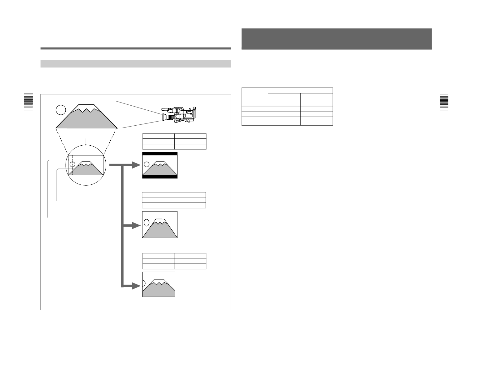
Video Output and Viewfinder Picture
The video output and viewfinder picture of this camera
vary as shown below according to the settings of the
16:9/4:3 item and the VF SCAN item of the Advanced
menu.
Subject
2
/3-inch optics
4:3 effective area
16:9 effective area
Item Settings
16:9/4:3 16:9
VF SCAN AUTO
The camera outputs 16:9
video. The scan size of the
viewfinder picture is 16:9 size.
Viewfinder picture
Item Settings
16:9/4:3 16:9
VF SCAN FULL
The camera outputs 16:9
video. The viewfinder picture
is 16:9 video that has been
stretched vertically to
completely fill the display area.
Viewfinder picture
Item Settings
16:9/4:3 4:3
VF SCAN AUTO or FULL
The camera outputs 4:3 video that
has been electronically extracted
from the effective area of the 16:9
aspect ratio. Compared to 16:9
video, this video appears as if a
zoom lens has been adjusted
slightly toward the telephoto end.
The picture in the viewfinder is 4:3
video, which completely fills the
display area.
Viewfinder picture
Advanced Menu Settings
17
Battery Pack Operating Times
The following table shows the maximum continuous
operating times when this camera (including
viewfinder) is operated at normal temperature under
battery pack power. The times varies depending on the
battery pack and attached equipment.
a) The DC-500 battery case is required when using the BP-
90A battery pack. The BP-90A cannot be used when a
camera adaptor is coupled to the camera.
Battery pack When the camera is coupled to:
Camera adaptor Portable VTR
(DSR-1/1P or
PVV-3/3P)
NP-1B Approx. 90 minutes Approx. 50 minutes
NP-1A Approx. 70 minutes Approx. 35 minutes
BP-90A
a)
— Approx. 105
minutes
DXC-D30WS/P(E)/V1
DXC-D30WS/P(E)/V1
18
..........................................................................................................................................................................................................
Gain levels Selectable –3 dB, 0 dB, 3 dB, 6 dB,
9 dB, 12 dB, 18 dB, 18 dB +
DPR, 24 dB, 24 dB + DPR, hyper
gain (30 dB + DPR)
Video output Composite signal
1.0 Vp-p, sync negative, 75 Ω,
unbalanced
Y/C separate signals
Y: 1.0 Vp-p, sync negative,
unbalanced
C: burst level 0.286 Vp-p
(DXC-D30WSL) or
0.300 Vp-p (DXCD30WSPL), no sync
Video S/N ratio 63 dB (typical) (DXC-D30WSL)
61 dB (typical) (DXC-D30WSPL)
Registration 0.05% for all zones, without lens
Input/output connectors
VIDEO OUT connector: BNC,
75 Ω, unbalanced
LENS connector: 12-pin, for
2
/3-
inch lens
VF connector (front): 20-pin
VF connector (left side): 8-pin
REMOTE connector 1: Stereo
mini-jack
REMOTE connector 2: 10-pin
MONITOR OUT connector: BNC,
75 Ω, unbalanced
Power supply 12 V DC
Power consumption
14.9 W (camera proper; 15.3 W
when connected with DSR-1/
1P)
17 W (when fitted with viewfinder)
Operating temperature
–10 °C to +45 °C (14 °F to 113 °F)
Storage temperature
–20 °C to +60 °C (–4 °F to 140 °F)
Mass 2.5 kg approx. (5 lb 8 oz)
Specifications
DXC-D30WSL/D30WSPL Camera Head
Imaging element Three-chip interline transfer CCD
Pixel resolution 980 (horizontal) × 494 (vertical)
(DXC-D30WSL)
980 (horizontal) × 582 (vertical)
(DXC-D30WSPL)
Imaging area 9.6 × 5.4 mm (
2
/3-inch)
Built-in filter settings
1: 3200K (3000K)
2: 5600K +
1
/8ND
3: 5600K
4: 5600K +
1
/64ND
Lens mount Bayonet mount
Signal standards EIA standard signal (NTSC color
system) (DXC-D30WSL)
CCIR standard signal (PAL color
system) (DXC-D30WSPL)
Scanning system 525 lines, 2:1 interlace (DXC-
D30WSL)
625 lines, 2:1 interlace
(DXC-D30WSPL)
Scanning frequencies
Horizontal:
15.734 kHz (DXC-D30WSL)
15.625 kHz (DXC-D30WSPL)
Vertical: 59.94 Hz (DXC-
D30WSL)
50.00 Hz (DXC-D30WSPL)
Synchronization Internal sync
External sync, using signal input
(VBS or BS) to the GEN LOCK
IN connector of an optional
camera adaptor or input from
the GEN LOCK connector of a
CCU-M5/M5P/M7/M7P camera
control unit to the VTR/CCU/
CMA connector of an optional
camera adaptor.
Horizontal resolution
1)
16:9: 700 TV lines
4:3: 700 TV lines
Minimum illumination
0.5 lx (at F1.4, +36 dB)
0.8 lx (at F1.8, +36 dB)
Sensitivity F11 at 2000 lx (3200K, 89.9%
reflectance) (typical)
1) About horizontal resolution measurement, see page 21.
19
1) When connecting a CA-512/512P, remove the blank
panel on the CA-512/512P.
..........................................................................................................................................................................................................
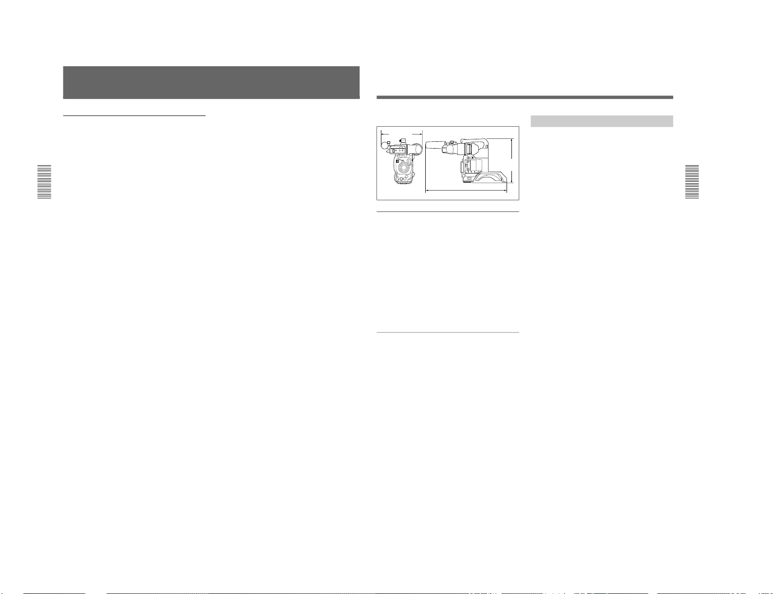
External dimensions in millimeters (inches)
DXF-701WS/701WSCE Viewfinder
Picture tube 1.5-inch monochrome
Indicators REC/TALLY (×2), TAKE, BATT,
SHUTTER, GAIN UP
Resolution 600 TV lines
Power supply 12 V DC
Power consumption
2.1 W
Mass 660 g approx. (1 lb 7 oz)
Maximum external dimensions
236 (W) × 85 (H) × 219 (D) mm
(9
3
/8 × 33/8 × 85/8 inches)
Scan size Switchable between 16:9 and 4:3
Supplied accessories
DXF-701WS/701WSCE Viewfinder (1)
RM-LG1 Remote Control Unit (1)
Microphone (1)
Wind screen (1)
VCT-U14 Tripod Adaptor (1)
Lens mount cap (1)
Flange focal length adjustment test chart (1)
Operating Instructions (common to DXC-D30 Series)
(1)
Operating Instructions (for DXC-D30WSL/D30WSPL
only) (1)
Operating Instructions (for RM-LG1) (1)
ClipLink™ Guide (1)
Design and specifications are subject to change
without notice.
Related Products
There is a range of Sony products available to meet
every conceivable video shooting requirement. For
details, consult your Sony sales representative or
supplier.
Lenses
VCL-915BYA/916BYA/916BY/918BY/1012BY
Zoom Lens
Camera adaptor products
CA-325A/325AP/325B/327/327P/511/512
1)
/512P1)/
513/537/537P Camera Adaptor
CMA-8A/8ACE AC Adaptor
RM-M7G Camera Remote Control Unit
VTR products
DSR-1/1P Digital Videocassette Recorder
EVV-9000/9000P Videocassette Recorder
PVV-1/1P/1A/1AP/3/3P Portable Videocassette
Recorder
VO-8800/8800P Portable Videocassette Recorder
BVU-150/150P Portable Videocassette Recorder
BVV-5/5PS Videocassette Recorder
BVW-50/50P Portable Videocassette Recorder
VA-5/5P/90/90P VTR Adaptor
Battery products
NP-1B Battery Pack
BP-90A Battery Pack
BC-1WD/1WDCE/410/410CE Battery Charger
Microphone products
ECM-670/672 Electret Condenser Microphone
C-74 Condenser Microphone
CAC-12 Microphone Holder
EC-0.5C2 Microphone Cable
EC-0.3C2 Micorphone Cable
Studio equipment
CCU-M5/M5P/M7/M7P Camera Control Unit
DFS-300/300P/500/500P DME Switcher
DCK-500/500P Chroma Key Unit
DXF-51 5-inch Viewfinder (monochrome)
DXF-41 4-inch Viewfinder (monochrome)
480 (19)
258
(10
1
/4)
242 (95/8)
1-5
1-6
20
Cables and miscellaneous
The suffix number on a cable part number indicates the
length in meters: e.g. a CCZ-A2 is 2 meters long.
(Approximate equivalents in feet: 2 m = 6 ft, 5 m = 16
ft, 10 m = 33 ft, 25 m = 82 ft, 50 m = 164 ft, 100 m =
328 ft)
Camera cables with Z-type 26-pin connectors
CCZ-A2/A5/A10/A25/A50/A100
Camera cables with Q-type 14-pin connectors
CCZQ-A2/A5/A10/A2AM
CCZZ-1B/1E Cable Extension Connector
Camera cables with Q-type 14-pin connectors
CCQ-2BRS/5BRS/10BRS
CCQ-10AM/25AM/50AM/100AM
LC-421 Carrying Case
LCR-1 Rain Cover
CAC-4 Chest Pad
LC-304SFT Soft Case
Specifications
21
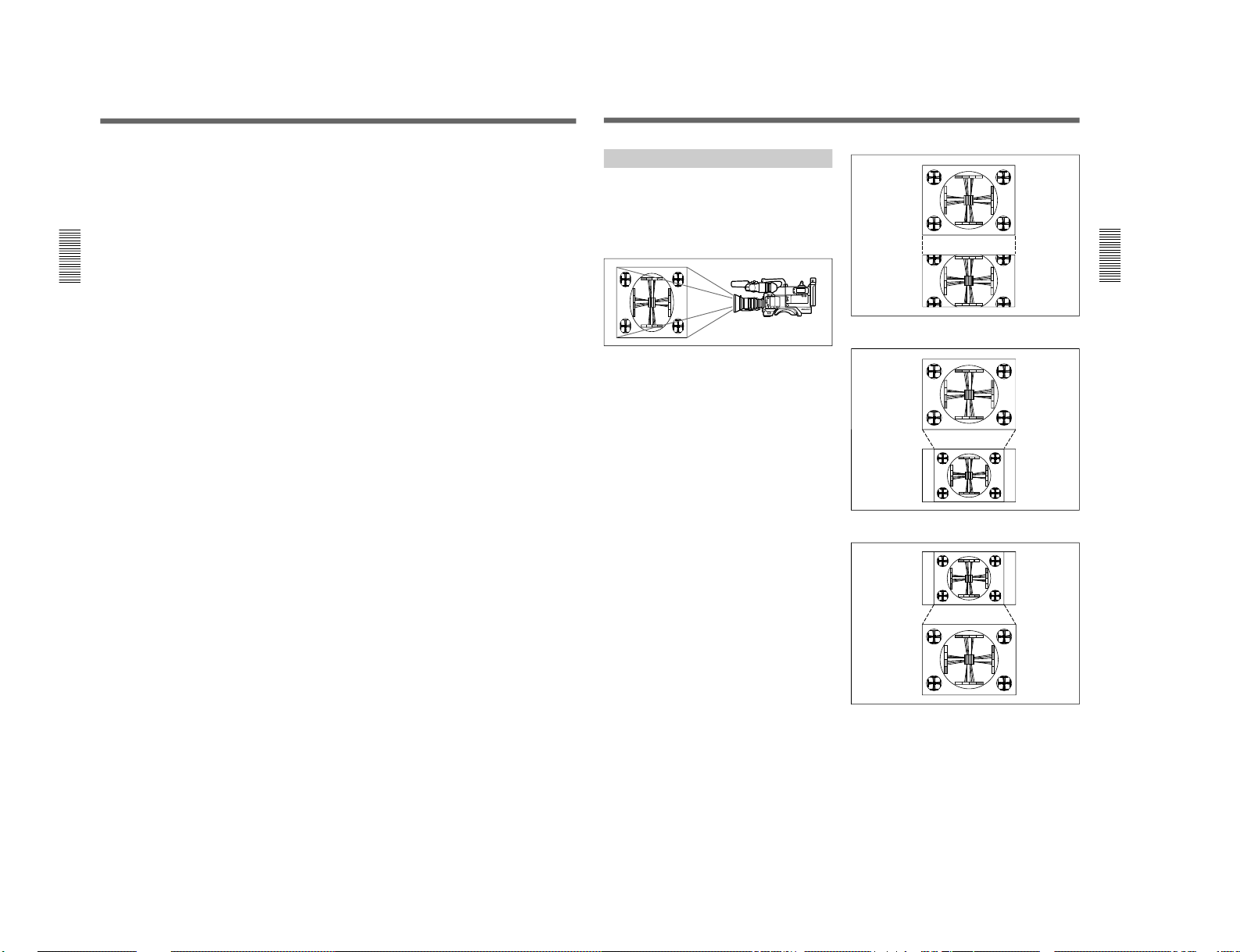
Measuring Horizontal Resolution
The number of effective pixels of this camera in
horizontal direction is 980. However, when horizontal
resolution measurement is executed using a 4:3
resolution chart, the results show a horizontal
resolution of approximately 700 TV lines for both 16:9
mode and 4:3 mode as described below.
Horizontal resolution in 16:9 mode
When the horizontal image frame of this camera is
aligned with the width of the 4:3 resolution chart, the
resolution is about 935 TV lines (see Figure A).
However, to measure the resolution of a video camera
precisely, the vertical image frame must be aligned
with the height of the chart. When this is done, the
resolution is approximately 700 (935 × 3/4) TV lines
(see Figure B).
Horizontal resolution in 4:3 mode
In 4:3 mode, frame memory is used to extract the 4:3
area from the 16:9 video signals produced by the WS
CCD, and the 4:3 signals are electronically enlarged.
As a result, the horizontal resolution is approximately
700 TV lines, the same as for 16:9 mode (see Figure
C).
4:3 resolution
chart
16:9 video
Horizontal
resolution:
Approx. 935
TV lines
Figure A.
Figure B.
Figure C.
4:3 resolution
chart
16:9 video
Horizontal
resolution:
Approx. 700
TV lines
16:9 video
4:3 video
Horizontal
resolution:
Approx. 700
TV lines
Horizontal
resolution:
Approx. 700
TV lines
DXC-D30WS/P(E)/V1
DXC-D30WS/P(E)/V1
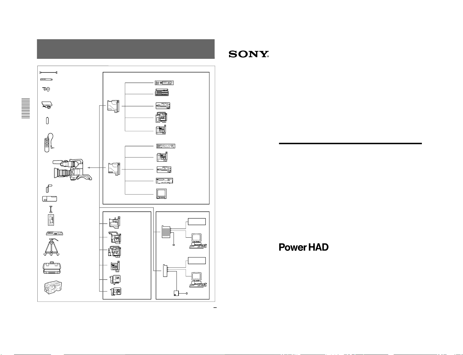
22
Chart of Optional Components and Accessories
EC-0.5C2 Microphone Cable
ECM-670/672 and C-74 Microphone
CAC-12 Microphone Holder
DXF-51/41
5-inch/4-inch Viewfinder
NP-1B Battery Pack
RM-LG1 Remote Control Unit
DXC-D30WS/D30WSP
CAC-4 Chest Pad
BC-1WD/1WDCE Battery
Charger
CCA-7 cable
RM-M7G Remote Control
Unit
VCT-U14 Tripod
Adaptor
Tripod
LC-421 Carrying Case
LCR-1 Raincover
CA-537/537P
Camera
Adaptor
CCZ-A cable
CCZ-A cable
CCZQ-A cable
CCZ-A cable
CCZQ-A cable
VA-90/90P + EVV-9000/9000P
CCU-M7/M7P/M5/M5P
Camera Control Unit
BVW-50/50P Betacam SP
VCR
VO-8800/8800P U-matic
VCR
VA-5/5P + BVV-5/5PS
CA-327/327P
Camera
Adaptor
CCQ-AM cable
CCQ-BRS cable
CCU-M5/M5P
Camera Control Unit
VA-90/90P + EVV-9000/
9000P
CCQ-BRS cable
VO-8800/8800P U-matic
VCR
S-video cable
Hi-8/S-VHS VCR
S-video cable
Video monitor
DSR-1/1P DVCAM
VCR
PVV-3/3P Betacam
SP VCR
CA-511 + BVV-5/5PS
Betacam SP VCR
EVV-9000/9000P Hi8 VCR
CA-512/512P +
S-VHS VCR
(Panasonic)
CA-513 + S-VHS
VCR (JVC)
CA-325A/325AP
Camera Adaptor
VCR
AC power source
Computer
CA-325B/325BP
Camera Adaptor
VCR
CMA-8A/
8ACE
Computer
AC power source
1996 by Sony Corporation
Operating Instructions
Before operating the unit, please read this manual
thoroughly and retain it for future reference.
3-858-217-14(1)
Color Video Camera
DXC-D30F/D30PF
DXC-D30K/D30PK
DXC-D30L/D30PL
DXC-D30H/D30PH
1-2. DXC-D30/D30P
1-7
1-8
2
LITHIUM BATTERY
Replace the battery with a Sony CR2032 lithium battery.
Use of another battery may present a risk of fire or
explosion.
WARNING
Battery may explode if mistreated.
Do not recharge, disassemble or dispose of in fire.
Note
Keep the lithium battery out of the reach of children.
Should the battery be swallowed, consult a doctor
immediately.
ADVARSEL!
Lithiumbatteri - Eksplosionsfare ved fejlagtig håndtering.
Udskiftning må kun ske med batteri af samme fabrikat og
type.
Levér det brugte batteri tilbage til laverandøren.
ADVARSEL
Lithiumbatteri - Eksplosjonsfare.
Ved utskifting benyttes kun batteri som anbefalt av
apparatfabrikanten.
Brukt batteri returneres apparatleverandøren.
VARNING
Explosionsfara vid felaktigt batteribyte.
Använd samma batterityp eller en likvärdig typ som
rekommenderas av apparattillverkaren.
Kassera använt batteri enligt gällande föreskrifter.
VAROITUS
Paristo voi räjähtää jos se on virheellisesti asennettu.
Vaihda paristo ainoastaan laitevalmistajan suosittelemaan
tyyppiin.
Hävitä käytetty paristo valmistajan ohjeiden mukaisesti.
For customers in the USA
This equipment has been tested and found to comply with
the limits for a Class A digital device, pursuant to Part 15 of
the FCC Rules. These limits are designed to provide
reasonable protection against harmful interference when the
equipment is operated in a commercial environment. This
equipment generates, uses, and can radiate radio frequency
energy and, if not installed and used in accordance with the
instruction manual, may cause harmful interference to radio
communications. Operation of this equipment in a
residential area is likely to cause harmful interference in
which case the user will be required to correct the
interference at his own expense.
You are cautioned that any changes or modifications not
expressly approved in this manual could void your authority
to operate this equipment.
The shielded interface cable recommended in this manual
must be used with this equipment in order to comply with the
limits for a digital device pursuant to Subpart B of Part 15 of
FCC Rules.
WARNING
To prevent fire or shock hazard, do not
expose the unit to rain or moisture.
To avoid electrical shock, do not open
the cabinet. Refer servicing to qualified
personnel only.
This symbol is intended to alert the user to
the presence of uninsulated “dangerous
voltage” within the product’s enclosure that
may be of sufficient magnitude to
constitute a risk of electric shock to
persons.
This symbol is intended to alert the user to
the presence of important operating and
maintenance (servicing) instructions in the
literature accompanying the appliance.
Owner’s Record
The model and serial numbers are located on the top.
Record these numbers in the spaces provided below. Refer
to them whenever you call upon your Sony dealer regarding
this product.
Model No.
Serial No.
Table of Contents
3
Chapter 2
Fitting and
Connection
Chapter 1
Overview
Table of Contents
Product Configurations ....................................................7
Features ............................................................................. 8
Location and function of Parts ...................................... 11
Camera Head ..................................................................... 11
VCL-916BYA Zoom Lens ................................................ 17
DXF-701/701CE Viewf inder............................................. 19
Replacing the Lithium Battery ....................................... 21
Fitting a VTR ....................................................................22
Using the Camcorder Grip ................................................ 23
Fitting the Lens ...............................................................26
Using Accessories ..........................................................28
Using the Viewfinder......................................................... 28
Using an Optional Microphone ......................................... 29
Fitting to a Tripod.............................................................. 31
Adjusting the Shoulder Pad Position................................. 31
Using the Carrying Case ................................................... 32
Connections ....................................................................33
Connecting a Portable VTR............................................... 33
Connecting a Number of Cameras (Using a Camera
Control Unit) ................................................................ 34
Connecting a Number of Cameras (Without Using
a Camera Control Unit)................................................ 36
Power Supply...................................................................37
Using Battery Packs .......................................................... 37
Camera Adaptor Power Supply......................................... 38
Basic Procedure for Shooting........................................39
Shooting with the DSR-1/1P...........................................41
Using the ClipLink Function............................................. 41
Using the Edit Search Function While Back Space
Editing .......................................................................... 43
Using the Freeze Mix Function......................................... 44
Chapter 3
Shooting
DXC-D30WS/P(E)/V1

DXC-D30WS/P(E)/V1
4
Table of Contents
Table of Contents
Chapter 5
Adjustments and
Settings
Chapter 4
Viewfinder Screen
Indications and
Menus
Table of Contents
Viewfinder Screen Indications .......................................45
Changing the Viewfinder Display ..................................... 45
Viewfinder Normal Indications.......................................47
Status Indications .............................................................. 50
Viewfinder Basic Menu ...................................................51
Basic Menu Operations ..................................................... 51
Contents and Settings of Each Page .................................. 51
Viewfinder Advanced Menu............................................57
Advanced Menu Operations.............................................. 57
Contents and Settings of Each Page .................................. 57
Setup Files .......................................................................62
Calling up a Setup File ...................................................... 62
Changing File Settings ...................................................... 64
Saving File Settings........................................................... 64
Using SetupNavi and SetupLog with the DSR-1/1P.....67
Setting up the camera Using Data Recorded on Tape....... 67
Recording the Menu Settings onto a Tape......................... 68
Viewing SetupLog Data .................................................... 69
White Balance Adjustment.............................................71
Saving an Appropriate White Balance Value
in Memory.................................................................... 71
Using the Preset White Balance Settings .......................... 72
Light Sources and Color Temperatures............................. 73
Using the ATW (Auto Tracing White Balance)
Function........................................................................ 73
Black Balance Adjustment .............................................74
Shutter Settings ..............................................................75
Setting the Clock and Timestamping Recordings........77
Viewfinder Screen Adjustments .................................... 79
Adjusting the Lens..........................................................80
Flange Focal Length Adjustment ...................................... 80
Iris Adjustments................................................................. 81
Macrophotography ............................................................ 82
(Continued)
Table of Contents
5
Chapter 5
Adjustments and
Settings
(Continued)
Settings for Special Cases .............................................83
Skin Detail Correction....................................................... 84
Adjusting Color in the Specified Area .............................. 84
Important Notes on Operation ....................................... 85
Characteristics of CCD Sensors ........................................ 85
Warning Indications........................................................86
Specifications..................................................................87
Related Products................................................................ 88
Chart of Optional Components and Accessories ........ 90
Appendixes
1-9
1-10
Chapter 1 Overview
Chapter 1 Overview
7
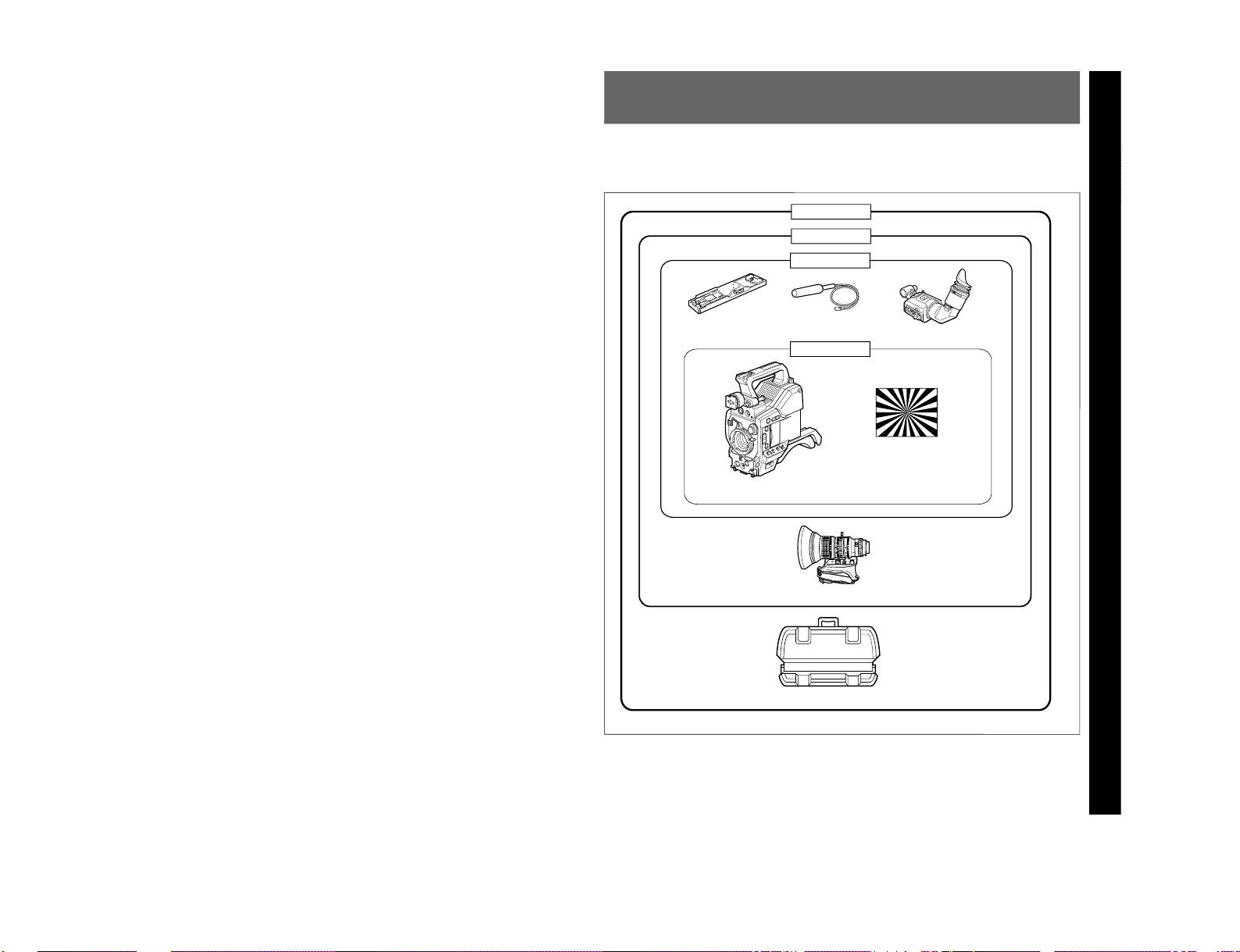
Product Configurations
Chapter 1 Overview
The eight models, DXC-D30F, DXC-D30K, DXCD30L, DXC-D30H, DXC-D30PF, DXC-D30PK,
DXC-D30PL, and DXC-D30PH, comprise both NTSC
and PAL versions and the components as shown in the
figure below. The operation of the basic camera unit is
the same in all cases.
Camera adaptor
The product kit does not include a camera adaptor: to
use a camera adaptor, you will need to purchase a
model CA-537/537P or CA-327/327P.
VCT-U14 Tripod
Adaptor
Microphone
DXF-701/701CE Viewfinder
DXC-D30H/D30PH
Test chart for flange
focal length
adjustment
DXC-D30/D30P Camera Head
LC-421 Carrying Case
VCL-916BYA
Zoom Lens
DXC-D30K/D30PK
DXC-D30L/D30PL
DXC-D30F/D30PF
DXC-D30WS/P(E)/V1

DXC-D30WS/P(E)/V1
Chapter 1 Overview
8
Chapter 1 Overview
Features
2
/3-inch IT type Power HAD CCD
The DXC-D30/D30P Color Video Camera uses
2
/3inch IT type Power HAD CCDs. It outperforms most
of the exiting FIT type CCD cameras for high-end use,
in both picture quality and sensitivity.
•Smear: –125 dB
•Sensitivity: F11.0 (at 3200 K, 2000 lux)
•S/N: 63 dB (DXC-D30) or 61 dB (DXC-D30P)
Sophisticated image processing
TruEye™ processing makes possible the following
performance features. This new digital signal
processing has brought reproduction of natural colors
to the level achieved by the human eye.
DynaLatitude™
Enables detailed adjustment of contrast control in each
pixel in accordance with a histogram of luminance
signal levels.
DCC+ (dynamic contrast control plus)
Prevents white breakup when shooting a high intensity
subject, and also prevents color faults in high intensity
subject.
Black stretch and compress
Enables control of luminance signal levels in black
areas without changing the hue.
Variety of detail corrections
•Skin detail function: this function gives a slightly
softer appearance to the subject’s face. The target
skin color can be automatically set.
•Black halo correction
•Red/green vertical detail correction: this function
performs vertical detail compensation for both red
and green signals.
•Horizontal detail frequency control
Recording and managing setup data
In addition to the setup menu that is displayed in the
viewfinder screen, the DXC-D30/D30P is equipped
with the following functions to facilitate camera head
setup.
Setup file system
You can use setup files when making adjustments or
settings. The DXC-D30/D30P comes with factory
preset files that contain shipped settings and you can
freely create user files as well.
Automatic recording of setup data (when
using DSR-1/1P)
When the DXC-D30/D30P is connected to the DSR-1/
1P VTR, two types of setup data can be recorded.
SetupLog™: Shooting-related environment settings
are recorded onto the tape at intervals of a few
seconds. This recorded data can then be used to
reproduce the same shooting conditions in
subsequent shots. It also makes it easier to
identify the causes of problems in previous shots.
SetupNavi™: The setup conditions selected with the
setup menu and setup files are recorded onto the
tape. The recorded setup data can be copied to
other camera heads so that the same setup can be
shared among several camera heads.
ClipLink™ Function (when using DSR1/1P)
The ClipLink function can be used at every step from
acquisition to editing. Information necessary for
editing is recorded when shooting to ensure fast and
efficient editing operations.
When you set a recording start (Rec IN) point or when
you press the TAKE button to set a Mark IN point, the
video image at that point is recorded on the tape in
compressed form as an Index Picture. In addition, the
time codes for such editing points (Mark IN/Mark
OUT points or cue points) are recorded along with
other editing point data (such as the cassette number
and scene number) into cassette memory (as ClipLink
log data). Unsuccessful scenes containing faults can
also be marked in cassette memory as “NG”, so that
only the good scenes are taken up from cassette
memory when editing.
Chapter 1 Overview
Chapter 1 Overview
9
Dockable with various types of VTRs
The DXC-D30/D30P docks with the DSR-1/1P
DVCAM VTR to configure the DSR-130/130P digital
camcorder. It also docks with the PVV-3/3P Betacam
SP VTR to configure the PVW-D30/D30P Betacam SP
camcorder. In addition, the DXC-D30/D30P docks
with the EVV-9000/9000P Hi-8 VTR. Using an
adaptor (not supplied), it is also able to dock with a
variety of existing S-VHS VTRs.
New Functions boost operability
EZ (easy) mode function
When there isn’t time to check the camera head
settings, simply press the EZ mode button to start the
auto adjustment function using standard settings.
There is no need to lose a shot for lack of setup time.
EZ (easy) focus
Press the EZ focus button before shooting to ensure a
quick and accurate focus.
Programmable gain
The amount of gain relative to the GAIN switch setting
(H, M, or L) can be programmed as –3 dB, 0 dB, 3
dB, 6 dB, 9 dB, 12 dB, 18 dB, 18 dB+DPR
1)
, 24 dB,
24 dB+DPR and hyper gain.
Hyper gain
Hyper gain (36 dB, or about 60 times greater than
0 dB) can be easily set via one switch setting. This can
also be done from remote equipment.
Auto tracing white balance
This function automatically traces the white balance,
which constantly changes as lighting conditions
change. Auto tracing white balance is especially
useful when there is no time to manually adjust the
white balance or when shooting moves between indoor
and outdoor locations.
Intensified auto iris control
In addition to the standard auto iris, the intelligent auto
iris function adjusts the lens iris to compensate back
lighting or spot lighting.
Total level control system (TLCS)
Even if the incoming light exceeds the range in which
the standard auto iris can control exposure, the auto
gain control (AGC) or auto exposure (AE) backs up to
ensure proper exposure.
Dual pixel readout (DPR)
When the gain is set to either 18 dB or 24 dB, the gain
setting can be doubled (6 dB up) without increasing
the noise level.
Recording time display
Recording time can be displayed in either of the
following modes.
•Total recording time for all cuts
•Total recording time for current cut
Viewfinder super detail
Video signals for the viewfinder are mixed with VDTL signals to make focusing easier.
Dual zebra pattern display
Two types of zebra patterns, zebra 1 and zebra 2 can
be displayed simultaneously or independently. The
zebra 1 can be set to the levels ranging from 70 to 90
IRE on the DXC-D30 (or from 70 to 90% on the DXCD30P) and the zebra 2 indicates the levels of 100 IRE
for the DXC-D30 or more (or the levels of 100% or
more for the DXC-D30P).
Color temperature display
When reading the white balance, the color temperature
is displayed on the viewfinder screen.
Video monitor output with text
The video signal with text superimposed that is shown
in the viewfinder can also be output to an external
video monitor.
Camera head microphone output indicator
An indication ≥ appears in the viewfinder whenever a
signal is being output from the camera head’s
microphone.
1-kHz reference signal output
Along with a color bar, a 1-kHz reference signal can
also be output.
..........................................................................................................................................................................................................
1) DPR = Dual Pixel Readout
1-11
1-12
Chapter 1 Overview
10
Chapter 1 Overview
Freeze mix function (when using DSR-1/1P)
The freeze mix function superimposes any previously
recorded still picture on the viewfinder screen to
facilitate framing the subject when reshooting the
scene.
Edit Search Function (when using DSR-1/1P)
When using the DXC-D30/D30P with the DSR-1/1P,
pressing the EDIT SEARCH buttons allow the tape to
play back in search mode. Set either of two playback
speeds.
Designed for ease of operation
Adjustable shoulder pad
You can move the shoulder pad forward or backward
to set a comfortable, well-balanced position.
Slide cover
The slide cover can hide the switches and buttons that
are seldom used during shooting. The cover can be
locked so as not to open during shooting.
High-performance viewfinder (DXF-701/
701CE)
•High resolution (600 TV lines of horizontal
resolution)
•Large-diameter eye cup for easier viewing and
focusing
•PEAKING potentiometer for vertical and horizontal
detail control
•Two indicators can be used as TALLY indicators
•Tough die-cast aluminum body
VTR data display
When connected to a VTR, the DXC-D30/D30P is
able to display the following data on the viewfinder
screen.
•Time values (counter, time code, or user bit vales)
•VTR audio levels
•Remaining tape time
•VTR operation mode
•Remaining battery capacity (when using an Anton
Bauer Intelligent Battery System)
•ClipLink information (when using the DSR-1/1P)
Features
Chapter 1 Overview
Chapter 1 Overview
11
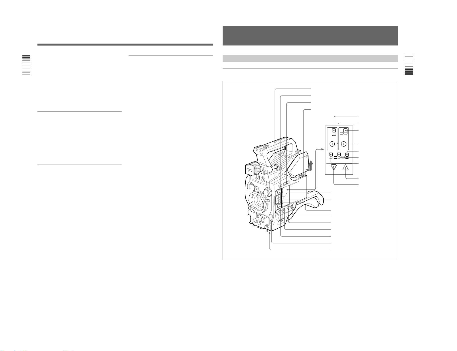
Camera Head
Right side view
TTL
DUR
OFF
ON
OFF
TTL RESET SET
REC TIME SKIN DTL
ON
OFF
FILE
STD
ON
OFF
ZEBRA HYPER
GAIN
SETUP
DOWN/OFF UP/ON
Location and Function of Parts
5 A.IRIS MODE switch and indicator
6 ATW button and indicator
7 POWER switch
8 MENU/STATUS switch
9 W. BAL switch
0 OUTPUT/DL/DCC+ switch
!¡ GAIN switch
!™ NG button
!£ Breaker switch
!¢ REC TIME switch
!∞ TTL RESET button
!§ SKIN DTL switch
!¶ SKIN DTL SET button
!• SET UP switch
!ª HYPER GAIN switch
@º ZEBRA switch
@¡ UP/ON button
@™ DOWN/OFF button
1 EZ MODE button and indicator
2 EZ FOCUS button
3 EDIT SEARCH buttons
4 Slide cover lock
DXC-D30WS/P(E)/V1

DXC-D30WS/P(E)/V1
Chapter 1 Overview
12
Chapter 1 Overview
5 A.IRIS (auto iris) MODE switch and indicator
When you use the auto iris function (by setting the iris
selector on the lens to A), set this switch to suit the
shooting conditions. Selecting BACK L gives more
light to back-lit subjects, and selecting SPOT L adjusts
for high contrast in spot-lit subjects. For normal
shooting, set this switch to STD.
6 ATW (auto tracing white balance) button and
indicator
Press this button, turning the indicator on, when you
want the white balance to be adjusted automatically to
follow changes in lighting conditions. (See page 73.)
7 POWER switch
This powers the camera on and off. There are two
different ON settings as follows.
ON STBY: This puts the VTR on standby. In this
state, pressing the VTR button on the camera
head, the lens or a camera adaptor starts recording
immediately.
ON SAVE: This puts the VTR in the power-saving
state, with the video head drum stationary. In this
state, it takes a few seconds to start recording after
pressing the VTR button.
Note
The VTR state when this switch is in the ON STBY or
ON SAVE position may depend on the VTR model.
8 MENU/STATUS switch
When you press this switch to the MENU position, the
basic menu is displayed. Keep pressing it to the
MENU position to cycle through the various menu
displays. When you press the switch to the STATUS
position, the DXC-D30/D30P’s status (of current
settings) is displayed.
9 W. BAL (white balance) switch
This selects the white balance setting from the preset
value, the value in memory A or the value in memory
B. (See page 71.)
0 OUTPUT/DL/DCC+ (DynaLatitude/dynamic
contrast control plus) switch
Use this switch to select the DCC+ function, the
DynaLatitude function, or color bar output.
Select the CAM/DCC+ position in most cases.
CAM/DCC+: This activates the DCC+ function.
This prevents color faults when shooting highintensity subjects.
Location and Function of Parts
1 EZ (“easy”) MODE button and indicator
Depress this button (EZ mode on) when you want to
be able to shoot immediately, with automatic
adjustment of the camera settings to standard values.
(See page 61.) When this function is used, the iris and
the white balance are adjusted automatically. (The
total level control system functions.) Press this button
again to return the camera to the previous settings (EZ
mode off).
Note
When connecting the CCU-M3/M5/M7 (or CCU-M3P/
M5P/M7P) Camera Control Unit or the RM-M7G
Remote Control Unit, the “easy mode” function is
disabled.
2 EZ FOCUS button
Press this button to turn the “easy focus” function on.
This opens the iris, to make it easier to focus before
beginning shooting. The indication “EZ FOCUS”
appears in the viewfinder while the function is on; to
turn it off, press the EZ FOCUS button again. If left
on, the function automatically turns off after about ten
seconds.
Note
If the “easy focus” function is still on when you press
the VTR button, it turns off automatically and
recording starts about one second later.
3 EDIT SEARCH buttons (for operation with
DSR-1/1P)
When using the DSR-1/1P to record, you can see the
search playback while pressing either of these buttons
at recording pause mode to quickly find the next
recording start point. Two playback speeds are
available, and press either of the buttons to the inner
position to increase the speed.
4 Slide cover lock
This lock keeps the slide cover closed.
LOCK FREE
LOCK FREE
EDIT SEARCH EDIT SEARCH
Unlocked position Locked position
Pull the upper panel forward and then lift it up.
Chapter 1 Overview
Chapter 1 Overview
13
CAM/DL: This setting uses the DynaLatitude
function, which finely adjusts the contrast of each
pixel according to a histogram of luminance signal
levels. Access advanced menu page 2 to set the
DynaLatitude function ON or OFF. The
DynaLatitude effect can be set to any of three
levels, Low, STD (standard), and High with basic
menu page 3.
BARS: This setting displays color bars.
For details of menu operation, see Chapter 4 “Viewfinder
Screen Displays and Menus”.
!¡ GAIN switch
This selects one of the three gain settings, high,
medium or low. You can choose the gain values
assigned to the H, M and L settings from values from
–3 dB to 24 dB + DPR and hyper gain. (See page 57.)
The factory default selections are 18 dB (H), 9 dB (M)
and 0 dB (L).
Note
When the HYPER GAIN switch !ª is in the ON
position, the GAIN switch has no effect.
!™ NG button
When using the ClipLink function during shooting,
you can designate a particular scene as “NG” (No
Good) by pressing this button before shooting the next
scene. Press the button again to cancel the NG setting.
!£ Breaker switch
If there is a fault in the camera power supply, the
breaker trips, and the camera power supply is
disconnected. Correct the fault in the power supply,
then press this switch.
!¢ REC (recording) TIME switch
This selects the recording time indication in the
viewfinder.
TTL: Displays the total recording time.
The total recording time is not reset even when
you stop the VTR and power off the camera, for
example, to replace the battery pack.
DUR: Displays the recording time of the current cut.
OFF/TC: Switches off the recording time display.
If, however, a PVV-3/3P is connected, and in the
advanced menus you set the time code display
item (TC IND) to ON (see page 59), then the VTR
time data (time code, CTL count, or user bit
value) is displayed.
Note
The recording time displayed when this switch is set to
the TTL or DUR position is obtained by counting the
duration of the internal reference signal input to the
camera.
The value may not agree exactly with the value
derived from the time code values. Furthermore, the
value displayed may not be correct when another
manufacturer’s VTR is connected to the camera.
!∞ TTL (total) RESET button
Pressing this button resets the total recording time
(TTL selection) to zero.
!§ SKIN DTL (skin detail) switch
Set this switch to ON to use the skin detail correction
function.
For details, see “Skin Detail Correction” (page 84).
!¶ SKIN DTL (skin detail set) SET button
Press this button with the SKIN DTL button !§ to
display the area detect cursor on the viewfinder screen.
Place the cursor on the target and press this button to
perform skin detail correction.
For details, see “Skin Detail Correction” (page 84).
!• SET UP switch
Use this switch to select the camera head setup
method.
STD: Set up using the setup menu. Setup file data is
not displayed.
FILE: Set up using setup files and the setup menu.
!ª HYPER GAIN switch
Setting this switch to the ON position increases the
gain by a factor of about 60 with respect to 0 dB (a 30
dB increase by electronic amplification and a 6 dB
increase for DPR, bringing about a total gain increase
of 36 dB).
When this switch is in the ON position, the indication
“HYPER” appears in the viewfinder, and the GAIN
UP indicator in the viewfinder also lights.
When finished shooting, return this switch to the OFF
position. The “HYPER” indication disappears and the
GAIN UP indicator goes out.
Note
Increasing the gain with this switch reduces the
horizontal resolution by 50%.
1-13
1-14
Chapter 1 Overview
14
Chapter 1 Overview
@º ZEBRA switch
Set this switch to the ON position to display a zebra
pattern (diagonal stripes) in the viewfinder.
Depending on the zebra setting in advanced menu page
4, the zebra 1 for video levels between 70 to 90 IRE
(or 70 to 90%) and the zebra 2 for video levels 100
IRE or more (or 100% or more) can be displayed
independently or simultaneously.
Location and Function of Parts
@¡ UP/ON button
Use this button to open displays and to make “ON”
settings. When using the advanced menus, use this
button to change menu pages or to switch to the
ordinary screen display.
@™ DOWN/OFF button
Use this button to close displays and to make “OFF”
settings. You can also use this button to change menu
pages when using the advanced menus.
Front view
1 MIC (microphone) IN +48 V connector (XLR 3pin, female)
Connect the supplied microphone or an optional
microphone (operable with a 48 V supply).
2 VF (viewfinder) connector (20-pin)
This is the connector for the DXF-701/701CE
viewfinder.
Note
When using this connector, do not connect a DXF40B/50B (or DXF-40BCE/50BCE) viewfinder to the
VF connector on the left side.
3 MIC LOW CUT switch
Set this switch to the ON position to insert a high-pass
filter in the microphone circuit, reducing wind noise.
Normally leave the switch in the OFF position.
4 FILTER control
Select the color temperature conversion filter
appropriate to the lighting conditions. (See page 39.)
5 Lens mount
Attach the zoom lens here.
1 MIC IN +48 V connector
2 VF connector
3 MIC LOW CUT switch
4 FILTER control
5 Lens mount
6 SHUTTER switch
7 TAKE button
8 AUDIO LEVEL knob
9 WHT/BLK switch
0 VTR button
Chapter 1 Overview
Chapter 1 Overview
15
6 SHUTTER switch
Use this switch to set the shutter speed, CLS (clear
scan), or EVS setting (see page 75). Usually, set this
switch to OFF.
7 TAKE button
Press this button to specify an editing point (Mark IN/
OUT or cue point) at the current tape position during
shooting.
8 AUDIO LEVEL knob
When the DSR-1/1P is attached, you can use this knob
to manually adjust the channel 1 audio recording level.
9 WHT/BLK (white/black) switch
This switch is used for automatic adjustment of the
white balance and black balance. (See pages 71 to 74.)
0 VTR button
Pressing this button starts and stops recording on the
VTR.
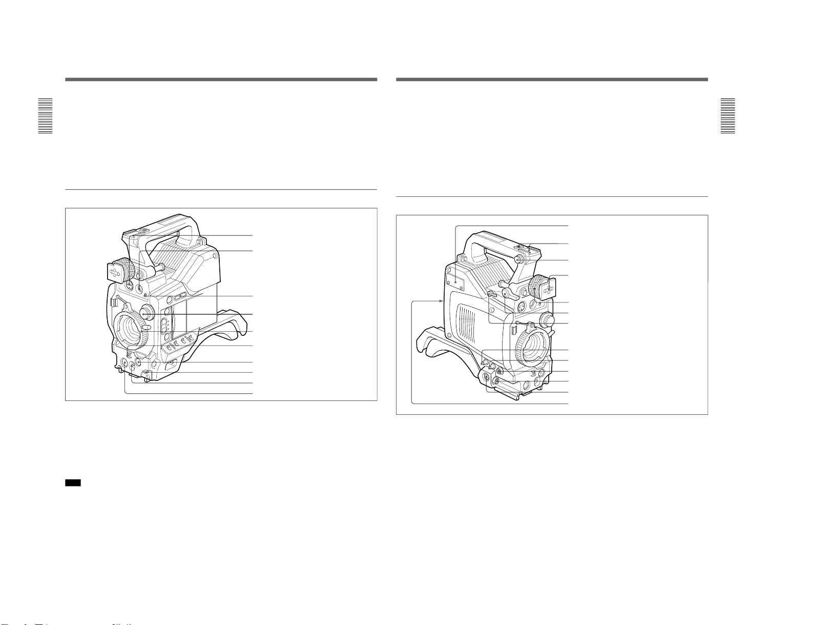
Left and upper view
1 Fitting for optional microphone holder
You can fit an optional CAC-12 Microphone Holder
here. (See page 29.)
2 Accessory fitting shoe and screw hole
Attach optional video lights or other accessories here.
3 Shoulder strap fixture
To use the supplied shoulder strap, fix one end here
and the other end to the VTR.
4 Viewfinder fitting shoe
Fix the DXF-701/701CE Viewfinder here.
5 Viewfinder left-to-right position fixing ring
Loosen this ring to adjust the left-to-right position of
the viewfinder. (See page 28.)
6 Viewfinder front-to-back position locking catch
Release this catch to adjust the front-to-back position
of the viewfinder. (See page 28.)
1 Fitting for optional microphone holder
2 Accessory fitting shoe and screw hole
3 Shoulder strap fitting
4 Viewfinder fitting shoe
5 Viewfinder left-to-right positioning ring
6 Viewfinder front-to-back position locking lever
7 REMOTE connector 1
8 MONITOR OUT connector
9 VIDEO OUT connector
0 REMOTE connector 2
!¡ LENS connector
!™ VF connector
!£ VTR connector
DXC-D30WS/P(E)/V1
DXC-D30WS/P(E)/V1
Chapter 1 Overview
16
Chapter 1 Overview
Location and Function of Parts
7 REMOTE connector 1 (mini-jack)
Use this connector to connect the switch for enabling
remote operation of the ClipLink function.
For details of connectable switches, contact your Sony
dealer.
8 MONITOR OUT connector (BNC)
Outputs both the camera video and the character
information as displayed on the viewfinder screen.
You can connect an optional LCD color monitor to this
connector.
9 VIDEO OUT connector (BNC)
This outputs the video signal captured by the camera.
0 REMOTE connector 2 (10-pin)
Connect the optional RM-M7G Remote Control Unit
to this connector. Set the CAMERA HEAD SELECT
switch on the bottom of RM-M7G to 1.
Notes
When using the RM-M7G, note the following points.
•When operating the camera head from the camera
control unit, connect the RM-M7G to the camera
control unit.
•EZ mode cannot be used if the RM-M7G is
connected to the camera head.
!¡ LENS connector (12-pin, for
2
/3-inch lens)
Connect the lens connector.
!™ VF (viewfinder)connector (8-pin)
This is the connector for the DXF-40B/50B (or DXF40BCE/50BCE) viewfinder.
Note
When using this connector, do not connect a DXF-701/
701CE viewfinder to the VF connector on the front of
the camera head.
!£ VTR connectors (PRO 76-pin DIGITAL and
PRO 50-pin)
Connect a dockable VTR. A PRO 76-pin DIGITAL
connector is for the DSR-1/1P and a PRO 50-pin
connector is for the PVV-3/3P or a camera adaptor.
Chapter 1 Overview
Chapter 1 Overview
17
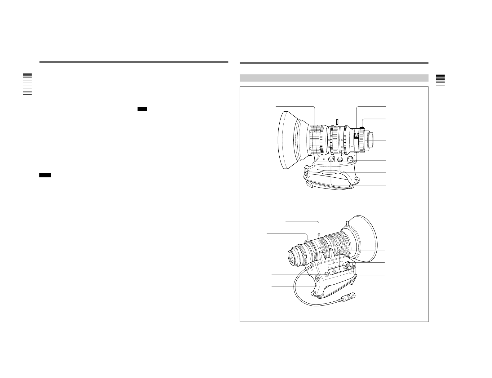
VCL-916BYA Zoom Lens
RET
W
T
M
A
1 Focusing ring
2 Manual zoom control
3 Iris ring
4 RET button
5 VTR button
6 Ff adjustment ring
7 MACRO button
8 MACRO ring
9 Zoom remote control
connector
0 Focus remote control
connector
!¡ ZOOM selector
!™ Power zoom switch
!£ Iris selector
!¢ Instant automatic iris
button
!∞ Lens connector
1-15
1-16
Chapter 1 Overview
18
Chapter 1 Overview
1 Focusing ring
Turn this ring to focus the lens on the subject.
2 Manual zoom control
For direct manual zoom control, set the ZOOM
selector to the “M” position, and turn this control.
3 Iris ring
For manual iris control, set the iris selector to the “M”
position, and turn this control.
4 RET (return) button
This allows you to check the video signal as follows.
When operating with a portable VTR connected
via other equipment: when the VTR is recording,
pressing this button connects the E-E video
signal
1)
from the VTR to the viewfinder.
When operating with a DSR-1/1P or PVV-3/3P
mounted on the camera head: when the VTR is in
recording pause mode, press this button to review
the last few seconds of the recording in the
viewfinder (recording review).
When operating with a CCU-M3/M3P/M5/M5P
M7/M7P Camera Control Unit connected: pressing
this button connects the return video signal from
the camera control unit to the viewfinder.
When this button is not pressed, the viewfinder
displays the video signal captured by the camera.
5 VTR button
When operating with a VTR: this button starts and
stops recording on the VTR. Press it once to start
recording, and once more to stop.
When operating with a CCU-M3/M3P/M5/M5P
M7/M7P Camera Control Unit connected: pressing
this button connects the return video signal from
the camera control unit to the viewfinder.
(Starting and stopping recording is controlled on
the VTR.)
6 Ff (flange focal length) adjustment ring
To adjust the flange focal length, loosen the screw on
this ring, then turn the ring. (See page 80.)
7 MACRO button
For close-up work, hold this button down while
turning the MACRO ring. (See page 82.)
8 MACRO ring
For close-up work, hold the MACRO button down
while turning this ring. (See page 82.)
9 Zoom remote control connector (8-pin)
For remote control of zoom operations, connect an
optional LO-23 Lens Remote Control Unit.
!º Focus remote control connector (3-pin)
This is not used.
!¡ ZOOM selector
This selects the mode of zoom operation.
S (servo): power zoom
M (manual): manual zoom
!™ Power zoom switch
Use this to carry out a power zoom.
W end: zoom toward wide angle
T end: zoom toward telephoto
Pressing the switch harder increases the zoom speed.
!£ Iris selector
This selects the mode of iris operation. (See page 81.)
A (automatic): automatic iris
M (manual): manual iris
!¢ Instant automatic iris button
While using manual iris control, press this button to
switch temporarily to the automatic iris control setting.
The automatic setting is maintained as long as you
hold the button down.
!∞ Lens connector
Connect this to the LENS connector on the camera
head.
1) E-E video signal: “electric-to-electric” video signal.
This is an output from the VTR of the input video signal
which has passed through internal electrical circuits, but
has not been converted to a magnetic signal in the heads
or on the tape.
..........................................................................................................................................................................................................
Location and Function of Parts
Chapter 1 Overview
Chapter 1 Overview
19
SHUTTER GAIN UP
TAKE
BATT
REC
TALLY
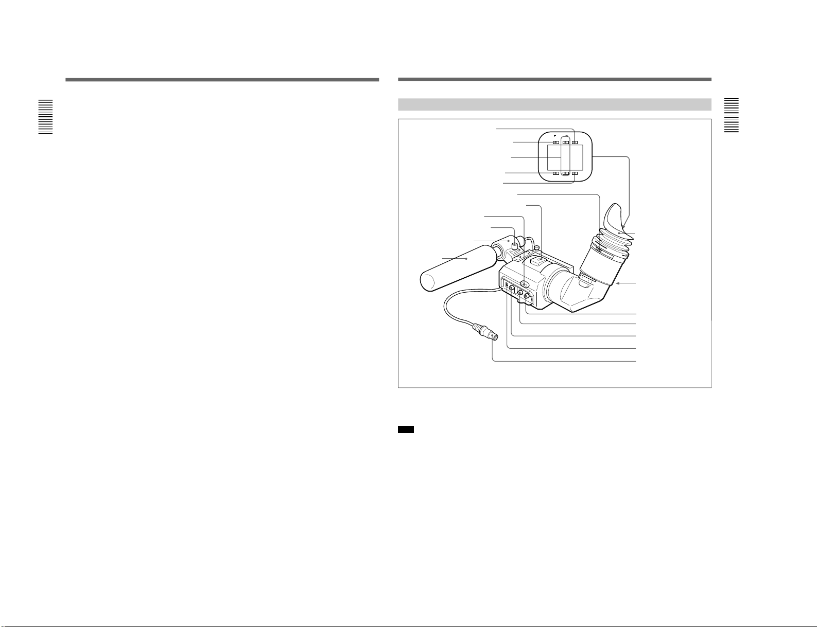
DXF-701/701CE Viewfinder
1 BATT indicator
2 TAKE/TALLY indicator
3 REC/TALLY indicators
4 SHUTTER indicator
5 GAIN UP indicator
6 Eyepiece focusing knob
7 Accessory fixing screw hole
8 Tally lamp
9 Eyepiece release catch
0 BRIGHT control
!¡ CONTRAST control
!™ PEAKING control
!£ TALLY switch
!¢ Viewfinder connector
Microphone holding screw
Microphone holder
Microphone
a)
Eye cup
a) Not supplied with the optional DXF-701/701CE
3 REC/TALLY (recording/tally) indicators (red)
•From the time when you press the VTR button on the
lens or camera head, this flashes until recording
starts, then stays on continuously during recording.
•When using a camera control unit, this lights when
the video from this camera is selected.
•This is also used to indicate a fault. (See page 86.)
•The lower indicator can be disabled by menu setting.
(See page 58.)
4 SHUTTER indicator (red)
This lights when the SHUTTER switch is in the ON
position. (If the EVS is selected, the indicator will not
light.)
1 BATT (battery) indicator (red)
This indicates when the battery capacity is low. (See
page 37.)
Note
When using a camera control unit, this indicator
flashes when you operate the controls, but this is not a
malfunction.
2 TAKE/TALLY indicator (orange)
When using the ClipLink function while shooting, this
indicator lights when the TAKE button has been
pressed to set a Mark IN point and goes out when a
Mark OUT point is set.
DXC-D30WS/P(E)/V1
DXC-D30WS/P(E)/V1
Chapter 1 Overview
20
Chapter 1 Overview
5 GAIN UP indicator (orange)
This lights when the gain is 3 dB or more.
6 Eyepiece focusing knob
Turn this to adjust the viewfinder focus to match your
eyesight. (See page 79.)
7 Accessory fixing screw hole
Attach optional video lights or other accessories here.
8 Tally lamp
When the TALLY switch is in the ON position, this
operates in the same way as the REC/TALLY
indicators 3.
9 Eyepiece release catch
To view the viewfinder screen directly, press this
catch, and hinge up the eyepiece.
0 BRIGHT (brightness) control
This adjusts the brightness of the viewfinder image.
(See page 79.)
!¡ CONTRAST control
This adjusts the contrast of the viewfinder image. (See
page 79.)
!™ PEAKING control
This adjusts the outline intensity of the viewfinder
image. (See page 79.)
!£ TALLY switch
Set this switch to the ON position to use the tally lamp
8.
!¢ Viewfinder connector (20-pin)
Connect this to the VF connector (front) on the camera
head.
Location and Function of Parts
Chapter 2 Fitting and Connections
Chapter 2 Fitting and Connections
21
Chapter 2 Fitting and Connections
The camera head uses a lithium battery (CR2032) to
retain date and time data.
When the lithium battery’s voltage falls, the clock
indication dose not appear. Replace the lithium battery
and set the clock (see page 77).
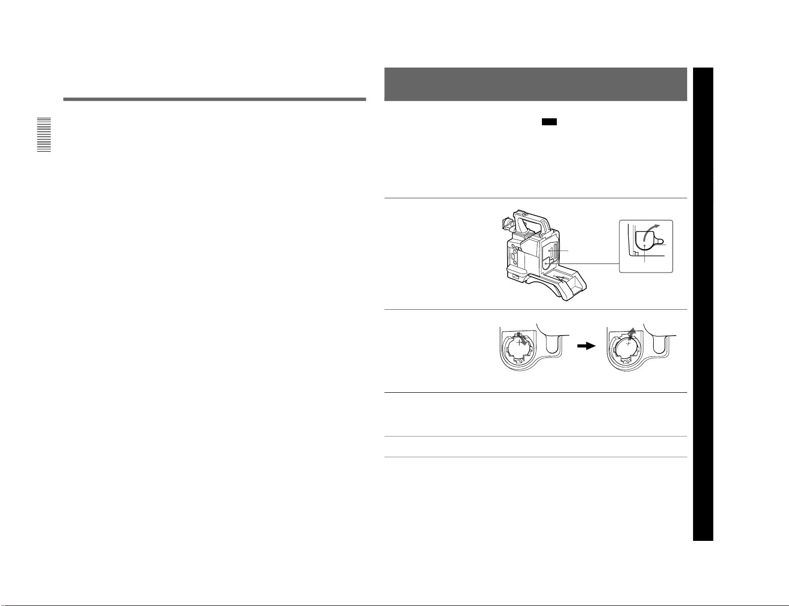
Replacing the Lithium Battery
Note
•Carefully read the instructions for replacing the
lithium battery. Lithium batteries may explode if
misused.
•Use only CR2032-type lithium batteries. Other types
of lithium batteries may come loose when the
camcorder is moved. If you have difficulty finding
CR2032-type lithium batteries, contact your Sony
dealer.
1
Pull the upper part of the
battery cover (on the rear of
the camera head) forward and
turn the cover clockwise.
For detaching the VTR or camera
adaptor, see “Fitting a VTR” next
page.
2
Take out the lithium battery.
3
Reverse step 2 to insert a
replacement lithium battery.
Make sure that the + symbol
on the battery is facing you.
4
Close the battery cover.
Press down and pull out toward you.
Rear of the
camera head
Battery cover
1-17
1-18
Chapter 2 Fitting and Connections
22
Chapter 2 Fitting and Connections
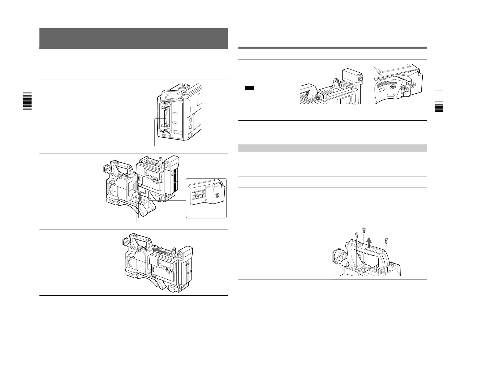
Fitting a VTR
1
Set the PRO 76-pin DIGITAL
connector on the DSR-1/1P.
For details, see the operating
instructions for the DSR-1/1P.
2
Align the projection on the
bottom of the DSR-1/1P with
the slot on the camera head.
3
Slide the DSR-1/1P and the
camera head together in the
groove as far as possible.
This section explains how to attach the DSR-1/1P to
the camera head. The method for attaching a PVV-3/
3P is similar.
When replacing the camera head grip with a camcorder
grip, see “Using the Camcorder Grip” (page 23).
Camera connector (PRO 76-pin DIGITAL)
DSR-1/1P
Projection
Slot
Groove
Camera head
(continued)
Chapter 2 Fitting and Connections
Chapter 2 Fitting and Connections
23
4
Tighten the two screws in the
grip connector and the two
screws in the shoulder pad
section.
Note
Slide the shoulder pad to its
central position before
tightening the screws.
Otherwise the screws may not
be properly fixed.
Screws
To remove the VTR
Reverse the fitting procedure.
To fit a camera adaptor
Follow the same procedure as when fitting a VTR.
Using the Camcorder Grip
camcorder grip and the method for attaching it differ
slightly depending on the type of VTR.
When using the camera head with a VTR as a
camcorder, you can replace the camera head’s grip
with a camcorder grip (not supplied). The type of
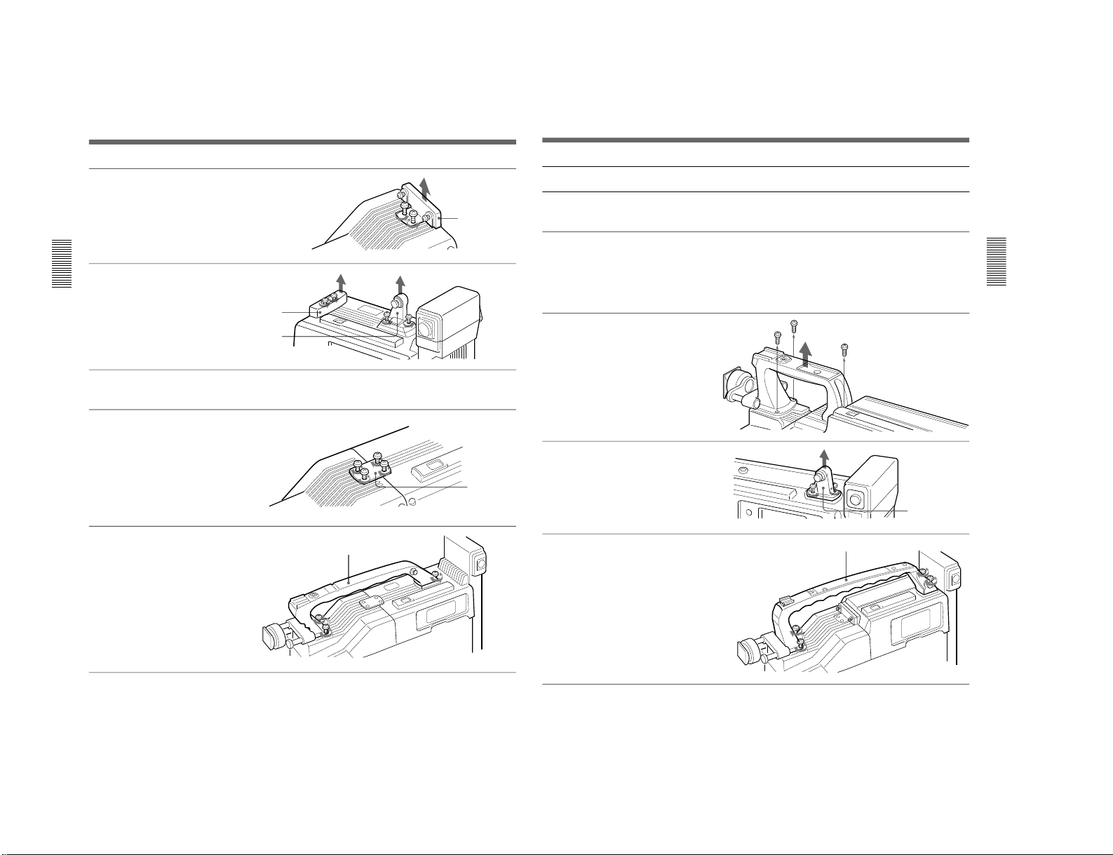
Attaching a camcorder grip to the DSR-1/1P
1
If the viewfinder is attached,
adjust the viewfinder to the
full-forward position.
For details, see “Adjusting the
viewfinder position” on page 28.
2
Remove the camera head
grip’s three screws, then pull
up the grip to remove it.
(continued)
DXC-D30WS/P(E)/V1
DXC-D30WS/P(E)/V1
Chapter 2 Fitting and Connections
24
Chapter 2 Fitting and Connections
Fitting a VTR
3
Remove the VTR connection
plate.
4
Remove the DSR-1/1P’s
shoulder strap fitting and the
camera head connection plate.
5
Perform the first three steps in
“Fitting a VTR”.
6
Screw the connection plate
(supplied with the grip for the
DSR-130/130P) which
straddles the connection
between the camera head and
the DSR-1/1P. Also, tighten
the two screws in the shoulder
pad section. (See step
4
on
page 23.)
7
Screw the grip for the DSR130/130P.
VTR connection
plate
Grip for the DSR-130/130P
Connection
plate
Camera head
connection plate
Shoulder strap
fitting
Chapter 2 Fitting and Connections
Chapter 2 Fitting and Connections
25
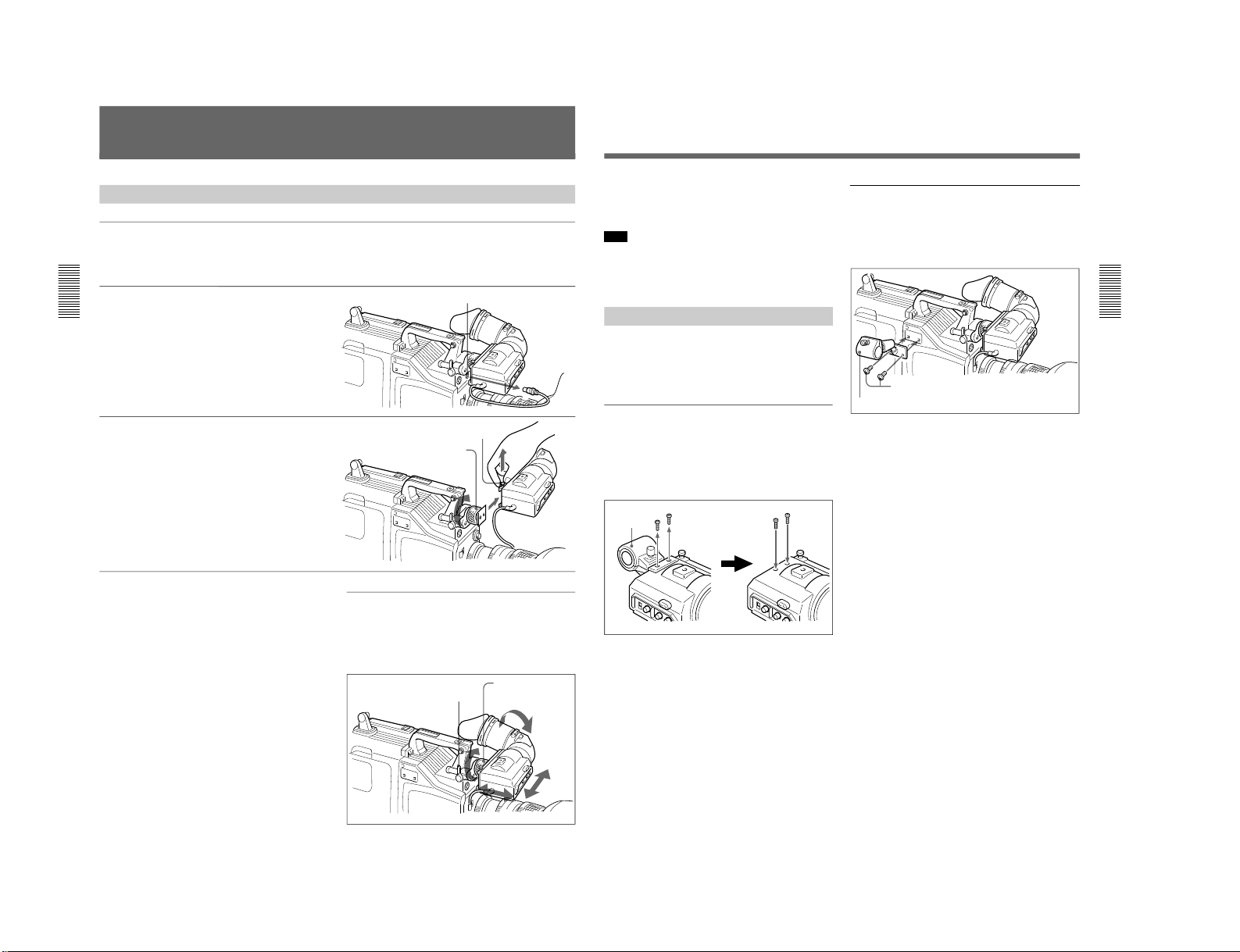
Attaching a camcorder grip to the PVV-3/3P
Shoulder strap
fitting
Grip for the PVW-D30/D30P
1
Perform steps 2 to 4 in “Fitting
a VTR”.
2
If the viewfinder is attached,
adjust the viewfinder to the
full-forward position.
For details, see “Adjusting the
viewfinder position” on page 28.
3
Remove the grip’s three
screws, then pull up the grip to
remove it.
4
Remove the PVV-3/3P’s
shoulder strap fitting.
5
Screw the grip for the PVWD30/D30P.
1-19
1-20
Chapter 2 Fitting and Connections
26
Chapter 2 Fitting and Connections
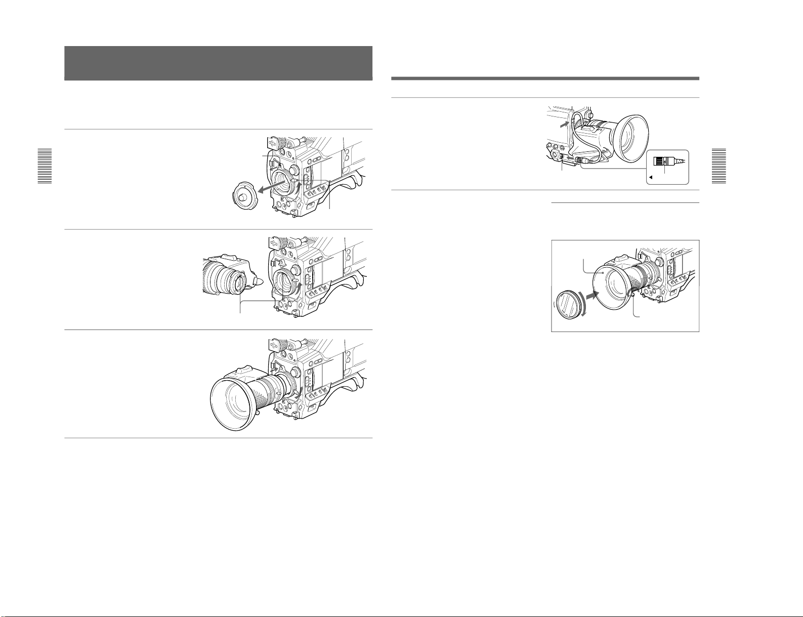
Fitting the Lens
In the case of the DXC-D30F/D30PF/D30K/D30PK
model, the lens is already fitted. In other cases, use the
following procedure to fit the lens.
1
Remove the retaining rubber
which prevents the lens mount
from coming loose, then raise
the lens fixing lever, and
remove the lens mount cap.
2
With the lens fixing lever
turned fully counterclockwise,
push in the lens, aligning the
projection on the lens with the
cutout on the camera.
3
Supporting the lens, turn the
lens fixing lever fully
clockwise. Replace the
retaining rubber on the lens
mount.
Retaining rubber
Lens mount cap
Lens fixing lever
Align and push in.
Chapter 2 Fitting and Connections
Chapter 2 Fitting and Connections
27
4
Using the triangular mark as a
guide, push the lens connector
into the LENS connector on
the camera head, until it clicks
into place. Fasten the cable
with the clamps.
LENS connector
Triangular mark
If using a lens with a 6-pin connector
This camera head has a 12-pin LENS connector. If the
lens cable has a 6-pin connector, fit an adaptor cable:
LO-612 (manufactured by Canon) or ECF-124
(manufactured by Fujinon) or equivalent.
Fitting optional filters
Loosen the lens hood fixing screw to remove the lens
hood, then attach the filter.
Remove lens hood
Lens hood fixing screw
Filter (optional)
DXC-D30WS/P(E)/V1
DXC-D30WS/P(E)/V1
Chapter 2 Fitting and Connections
28
Chapter 2 Fitting and Connections
Using the Viewfinder
Removing the Viewfinder
Remove any microphone from the viewfinder before
beginning.
1
Pull the viewfinder connector
out of the VF connector on the
front of the camera head.
2
Loosen the viewfinder left-toright position fixing ring, then
pulling up the retaining catch,
slide the viewfinder out.
VF connector
Retaining catch
Viewfinder left-to-right
position fixing ring
To fit the viewfinder
Reverse the removal procedure.
Adjusting the viewfinder position
To adjust the viewfinder left-to-right position, loosen
the left-to-right fixing ring, and to adjust the front-toback position loosen the front-to-back position locking
catch.
Viewfinger front-to-back
position locking catch
Viewfinder left-to-right
position fixing ring
Using Accessories
Chapter 2 Fitting and Connections
Chapter 2 Fitting and Connections
29
Left eye adaptor
By fitting a left eye adaptor, you can use the camera
with your left eye to the viewfinder.
Note
You cannot stow the camera attached with a left eye
adaptor in the LC-421 Carrying Case.
For details, consult your Sony dealer.
Using an Optional Microphone
To use a long microphone such as the optional ECM670/672, remove the supplied microphone holder, and
fit an optional CAC-12 Microphone Holder to the
camera, then mount the microphone in this holder.
Removing the supplied microphone
holder
Remove the two microphone holder retaining screws
(M4 × 6) from the viewfinder, remove the microphone
holder, then replace the screws in their original
positions.
Fitting the optional CAC-12 Microphone
Holder
Remove the two retaining screws (M3 × 8) for the
optional microphone holder, then use these screws to
attach the CAC-12 Microphone Holder.
Screws removed from the camera
CAC-12
Microphone
holder
M4 × 6 screws
1-21
1-22
Chapter 2 Fitting and Connections
30
Chapter 2 Fitting and Connections
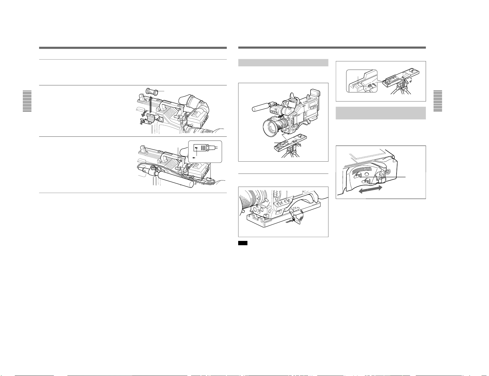
Fitting an optional microphone
Use the following procedure to attach an optional
ECM-670 Microphone.
1
Loosen the screw of the CAC12 Microphone Holder, then
open the holder and replace the
microphone adaptor with the
one supplied with the ECM670 Microphone.
2
Insert the microphone in the
microphone holder, close the
holder, and tighten the screw.
Connect the microphone cable
to the MIC IN +48 V
connector.
Microphone adaptor
MIC IN +48 V connector
Mark
Fitting optional microphones (operable with a
48 V supply) other than the ECM-670
Use the same fitting procedure as for the ECM-670,
but note the following differences with respect to the
microphone adaptor.
ECM-672: no microphone adaptor required.
Slender microphones (19 mm (
3
/4 inch) diameter):
use the microphone adaptor supplied with the
CAC-12.
Using Accessories
Chapter 2 Fitting and Connections
Chapter 2 Fitting and Connections
31
Fitting to a Tripod
First fit the VCT-U14 Tripod Adaptor to the tripod,
then mount the camera on the tripod adaptor.
Removal
Note
After removing the camera, if the tripod adaptor pin
has not returned to its original position, hold down the
red button and move the lever in the direction of the
arrow to return the pin to its original position. It is not
possible to mount a camera with the pin left out.
VCT-U14 Tripod Adaptor
Side the camera forward
along the slot, until it clicks
firmly into place.
Tripod
Hold down the red button
and pull the lever in the
direction of the arrow.
Adjusting the Shoulder Pad
Position
You can slide the shoulder pad toward the front or
back by up to 10 mm from its central position (as when
shipped). Adjust it to get the best balance when using
the camera on your shoulder.
Optional CAC-4 Chest Pad
When using the camera on your shoulder, attaching the
optional CAC-4 Chest Pad reduces the load on your
right hand supporting the zoom lens, and makes
operation easier.
For details see the instructions provided with the CAC-4.
Pin
1
2
Adjust the position, then
tighten the screws.
Loosen the
two screws.
DXC-D30WS/P(E)/V1
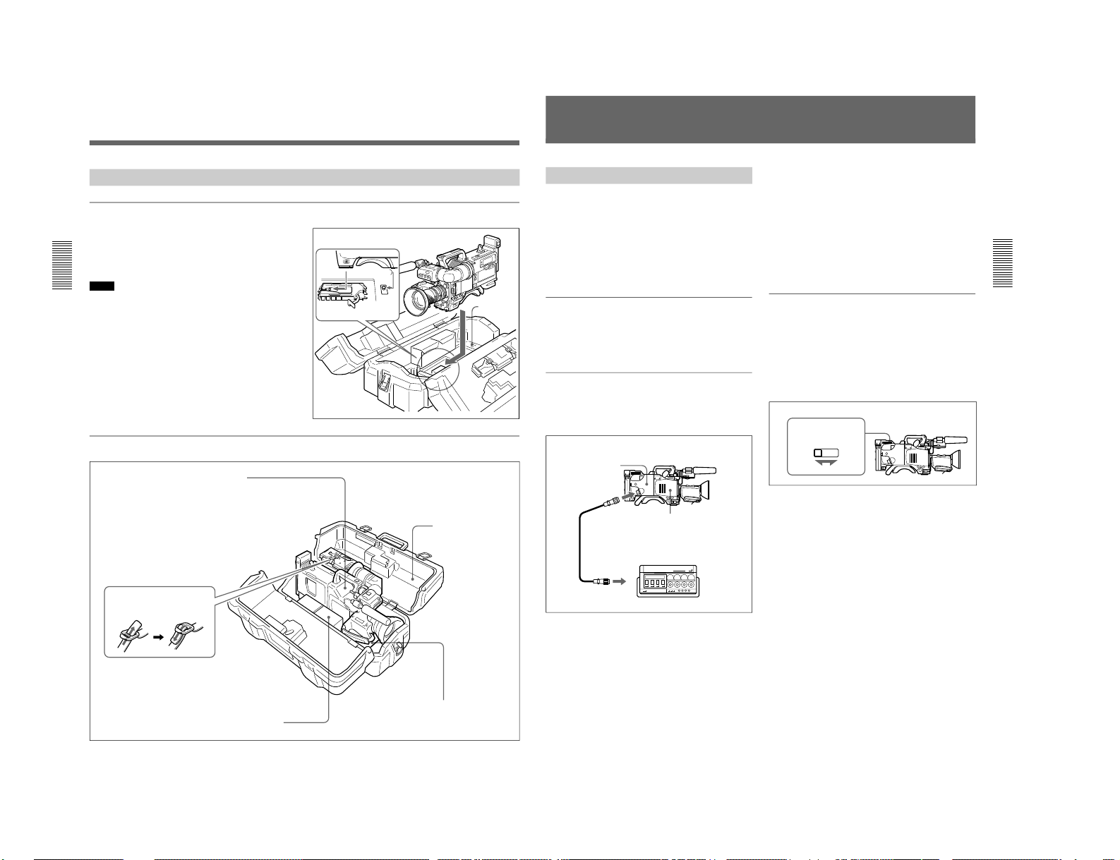
DXC-D30WS/P(E)/V1
Chapter 2 Fitting and Connections
32
Chapter 2 Fitting and Connections
Using the Carrying Case
Stowing the camera
Align the camera with the base of the case, and slide
the camera in forward.
Checking that the pin at the rear engages correctly,
push forward until it locks into place.
Notes
•Bring the viewfinder into the horizontal position,
slide it fully rearward and to the left, then fix before
stowing.
•When an optional microphone (ECM-670/672, C-74,
etc.) is attached, loosen the microphone fixing
screws, move the microphone to the lowest position,
and fix before stowing.
Example of fully-stowed carrying case
Align the camera with the base of the
carrying case.
Lever
Base
VCT-U14 Tripod Adaptor
Fasten straps.
LC-421 Carrying
Case
NP-1A/1B Battery Packs
(maximum two) - Fasten straps.
DXC-D30/D30P Color Video Camera
This can be stored with the following system
component fitted.
• CA-537/537P/327/327P/325A/325AP/325B
Camera Adaptor or DSR-1/1P, PVV-3/3P or
EVV-9000/9000P
• DXF-701/701CE Viewfinder
• ECM-670/ECM-672/C-74 Microphone
• Zoom lens (VCL-916BYA etc.)
(Largest lens which can be stowed is
Canon J18 X 8.5BI-B.)
• CAC-12 Microphone Holder
• CAC-4 Chest Pad
Cassettes, camera cables, etc.
Using Accessories
Chapter 2 Fitting and Connections
Chapter 2 Fitting and Connections
33
Connections
Connecting a Portable VTR
Using the optional CA-537/537P or CA-327/327P
Camera Adaptor and a camera cable, you can connect
a portable VTR. Set the VTR selector switch on the
camera adaptor according to the VTR connected.
If using a VTR from another manufacturer, consult your
Sony dealer.
Checks before making connections
Check first that the video camera, camera adaptor,
VTR, and other devices are all powered off.
Making connections
Using a camera cable, connect the VTR/CCU/CMA
connector on the camera adaptor to the camera input
connector of the VTR.
Camera cable
•Select a camera cable to fit the camera input
connector on the VTR you are using.
•The maximum camera cable extent is 10 m (33 ft).
For details, consult your Sony dealer.
Video monitor
•If using an S-VHS VTR, using a video monitor with
an S-video input connector and connecting it to the Svideo connector of the VTR will allow you to
monitor a clear picture, with no flecking.
•The output video signal from the VIDEO OUT
connector of this unit is a composite video signal.
Connect the VIDEO OUT connector of this unit to a
composite video signal input connector of the
monitor.
Setting the VTR selector switch on the
camera adaptor
When using the camera with a CA-537/537P/327/327P
Camera Adaptor, it is essential to correctly set the
VTR selector switch on the camera adaptor according
to the VTR connected. This switch determines the
type of video signal output from the VTR/CCU/CMA
connector and the audio output signal level.
Example: Connecting a BVW-50/50P Portable VTR to a CA-537/
537P Camera Adaptor
26-pin connector
VTR/CCU/CMA
DXC-D30/D30P
CCZ-A Camera Cable
26-pin connector
CAMERA IN
BVW-50/50P Portable VTR
CA-537/537P Camera
Adaptor
Example: When using a CA-537/537P
13
2
VTR SELECT switch
1-23
 Loading...