

Page 1
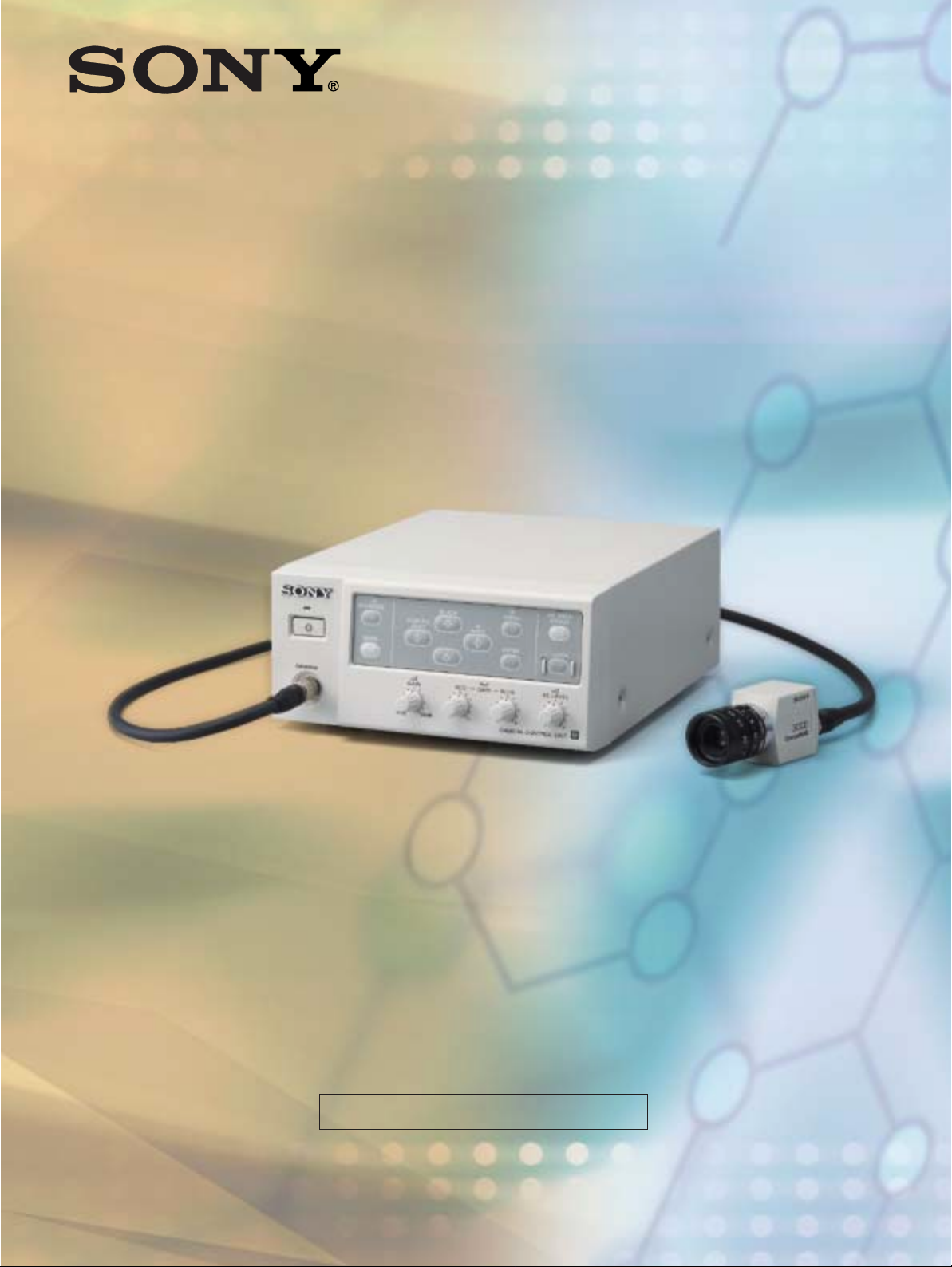
SONY 3-CCD Color Video Camera
DXC-C33/C33P
Product Information Manual
For use of authorised dealers
Page 2

Page 3

CONTENTS
1. PRODUCT CONCEPT P. 2
2. APPLICATIONS P. 3
3. KEY FEATURES P. 4
4. MENU FUNCTION P. 9
5. CAMERA CONNECTORS P. 12
6. CONNECTOR PIN ASSIGNMENTS P. 14
7. SPECIFICATIONS P. 15
8. OPTIONAL ACCESSORIES P. 18
9. SYSTEM EXAMPLES P. 22
10. DIMENSIONS P. 25
11. TECHNICAL APPENDIX P. 26
12. Q & A P. 30
DXC-C33/C33P
Page 4

1. PRODUCT CONCEPT
1. PRODUCT CONCEPT
remote-head type camera
DXC-C33/C33P
High-performance,
●
Small and light camera head unit
●
C mount 3-CCD
●
High picture quality
●
DV output
●
Digital signal processing
2
–
DXC-C33/C33P Product Information Manual
Page 5
2. APPLICATIONS
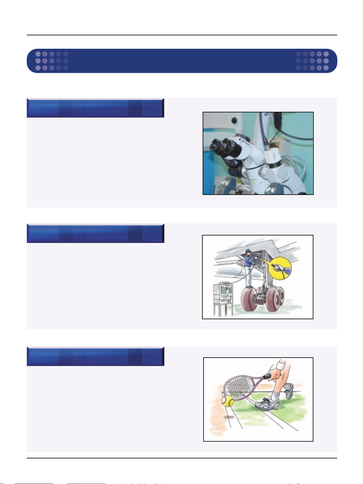
Medical
Surgical microscopy
Slit lamp
2. APPLICATIONS
Industrial inspection
Semiconductor
Tube
Special angle shooting
Sports
Production
DXC-C33/C33P Product Information Manual –3
Page 6
3. KEY FEATURES
Basic Specifications
Horizontal resolution 850 TV lines
Signal to Noise (S/N) ratio NTSC: 62 dB (typical)
Sensitivity F8.0 at 2000 lux (3200 K)
Minimum illumination 4 lux (F2, GAIN: Hyper)
Output signal DV, VBS, RGB/SYNC, Y/C
Dimensions (W x H x D) CHU: 32 x 38 x 40 mm (15/16x 11/2x 15/8inches)
Power consumption Max. 18 W
Mass CHU: 48 g (1.7 oz)
3. Key Features
3. KEY FEATURES
PAL: 61 dB (typical)
CCU: 200 x 88 x 242 mm (77/8x 3
CCU: 2.5 kg (5 lb 8 oz)
1
/
x 9
2
5
/
8
inches)
Features
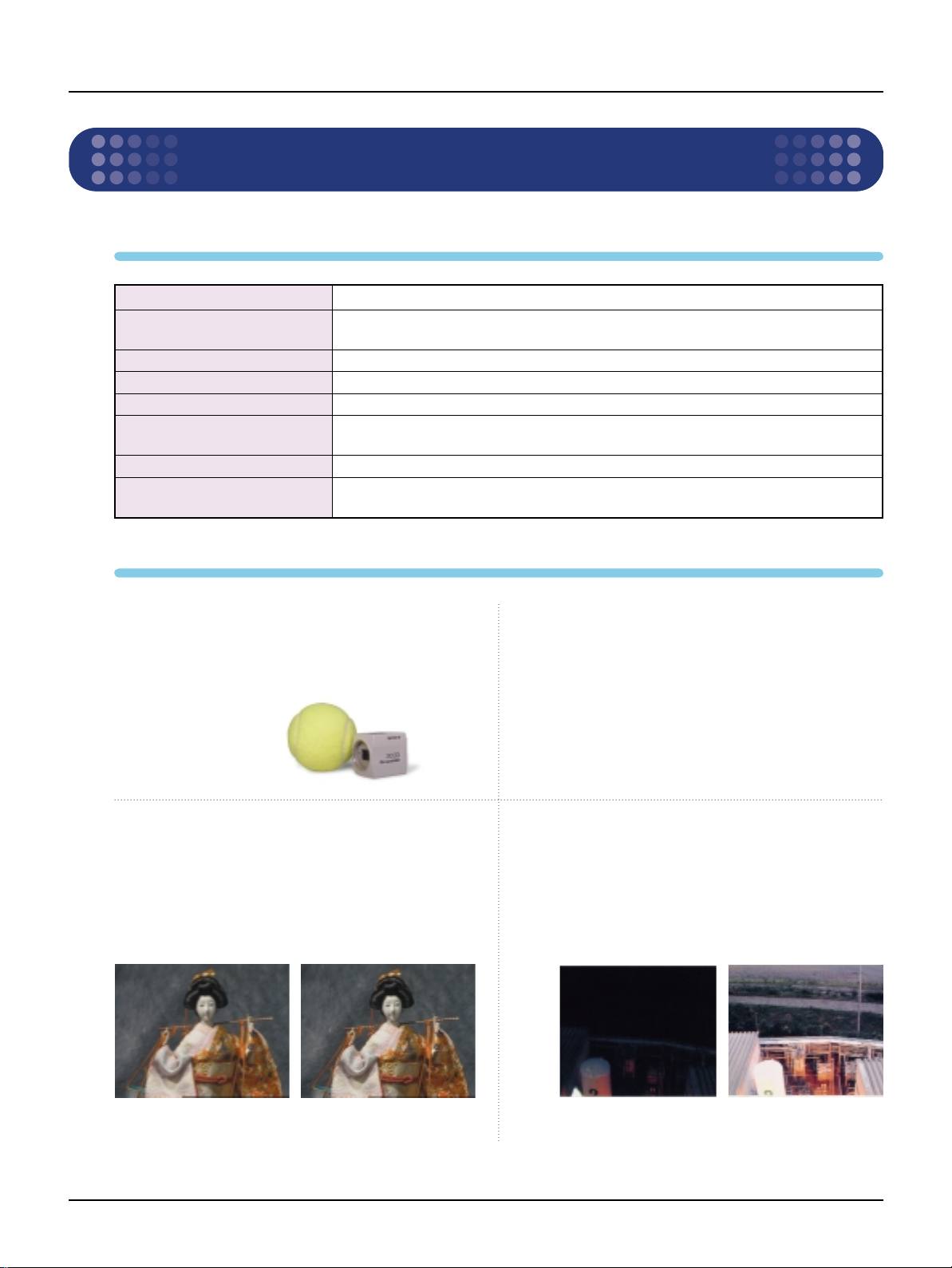
■Small camera head
The DXC-C33/C33P can be installed in space-limited
locations. The size of the camera head unit (CHU) is
one of the smallest of all the 1/3 type 3-CCD
cameras.
■High picture quality
The DXC-C33/C33P can clearly capture detailed
object images. Using three 1/3 type CCDs, the
camera can realize 2000 lux at F8, a S/N ratio of 62
dB (NTSC) or 61 dB (PAL) and achieve a horizontal
resolution of 850 TV lines.
■10-bit DSP
The DXC-C33/C33P can capture superior pictures
by adopting full Digital Signal Processing (DSP) of
10 bits.
■Frame memory
Built-in frame memory can provide a remakable
freeze image and enhanced image sensitivity by
the Long-Term exposure function. Images captured
by the Long-Term exposure function can be output
continuously .
800 TV lines picture 850 TV lines picture
4
–
DXC-C33/C33P Product Information Manual
Gain: 18 dB Long exposure: 32 frames
(Simulated picture)
Page 7

■Partial Enhance
<MULTI>
<SPOT>
<LARGE>
<SLIT>
<MID>
<MANUAL>
OPTIONAL AREA
This function allows a particular color to be selected, and its
hue, saturation and detail to be altered. In addition, the detail
produced by the high resolution of the camera can be
softened or emphasized in certain parts of the image with the
Partial Enhance function.
3. KEY FEATURES
OFF ON
■User-friendly control panel
The front panel is very easy to use with good-sized
switches that are smartly arranged.
■Two AE areas preset
AE (Automatic Exposure) function is very useful in
determining the best area for incoming light metering.
Users can select and set up two of the six different AE
modes and can easily switch them on the front panel.
• The Multi mode measures the luminance level on
the 9 divided windows and the center window is
weighted compared to the others.
• In Manual mode, the user can freely define the
light metering area.
■RS-232C interface
Easy control and operation of the camera by an
external computer is possible. For details of the
RS-232C protocol, please refer to the Control
Protocol or contact your nearest Sony office.
■External synchronization
(VBS Genlock, HD/VD)
The DXC camera can be synchronized with an
external VBS signal from other equipment and
includes a SC/H phase adjustment control. HD/VD
sync signals also can be accepted. This is very
useful in multiple camera operation and in
connection with frame grabber boards.
■Color shading compensation
The color shading compensation feature provides a
uniformed color for images displayed on the screen.
DXC-C33/C33P Product Information Manual –5
Page 8

3. KEY FEATURES
The DVCAM format is optimized for professional editing, based on and maintaining cross play with the DV format.
Digitization
• High-quality picture and sound
• Superb dubbing quality
• Unique functions provided by compression technology
High-performance editing
capabilities for professional use
• SMPTE/EBU time code
• RS-422A interface
• Newly developed mechanism
■ i.LINKTM(DV) out
DV (Digital Video) is the standard for consumer digital video. DV complies with the same IEEE1394 interface
standard as the DFW Series. Thanks to data-compression technology, the transmission speed of DV is
approximately 25 Mb/s. This figure is about 1/5 of the transmission speed of the DFW Series (no compression).
DV can be connected to a PC and various application software is available for DV. Users can therefore enjoy the
high quality of DV compression with the excellent line-up of the DVCAM Series. The DXC-C33/C33P is equipped
with a DV output terminal so that images can be recorded into an i.LINK interface-equipped VTR with no quality
deterioration.
This feature is first to be introduced to small 3-CCD cameras.
* i.LINK stands for IEEE-1394-1995 standards and their revisions.
Note: Sony VAIO computers are checked with Sony DV products, but not with DVCAM, concerning the i.LINK interconnection.
Some VAIO application software may not work with DVCAM.
Why was the DVCAM format Born?
CONCEPT - What is the benefit of the DVCAM for the DXC-C33/C33P?
The DVCAM format was developed to meet the following key demands:
• Digitization (trend from analog to digital)
• High-performance editing capabilities for professional use
• Full compatibility with the DV format
6
–
DXC-C33/C33P Product Information Manual
Page 9

The DVCAM & DV format
DVCAM
DV
Consumer use
Professional use
• 15µm track pitch
• Audio lock recording
✱
• 10µm track pitch
• Audio unlock recording
✱
Audio mode and audio channel are not available in the DXC-C33/C33P
✱
• 5 : 1 DV compression method
• New advanced ME tape
• Standard size & Mini size cassettes
• 2CH & 4CH audio recording modes
✱
3. KEY FEATURES
The DVCAM format
The DVCAM format, which is available for the DXC-C33/C33P is, a professional development of the DV format.
Specific advantages, shown below, mean it is optimised for professional editing.
The features and benefits of DVCAM format
◆ 5:1 DV compression
• Longer duration recording (max. 3 hours)
• High-speed data transfer capability
◆ Digital components
• High-quality picture
• Superb dubbing quality via QSDI & DV I/O
◆ Cassette memory
• Newly developed ClipLink system for top-of-the-range DVCAM VTRs
• Photo mode for mid-range DVCAM VTRs
DXC-C33/C33P Product Information Manual –7
Page 10
3. KEY FEATURES
Comparison of 1/4 inch DVCAM, DV, and DVCPRO
Format DVCAM DV DVCPRO
Compression method 5:1 DV compression 5:1 DV compression 5:1 DV compression
Tape material ME ME
Cassette size Standard / Mini Standard / Mini L / M
Track pitch 15µm10µm (LP : 7.5µm) 18µm
Tape speed 28.193 mm/s 18.812 mm/s 33.820 mm/s
Compatibility cassette Playback of Mini
with Home DV (Adaptor required)
Audio mode Lock mode* Unlock mode Lock mode
Audio channel 16bit 2ch / 12bit 4ch* 16bit 2ch / 12bit 4ch 16bit 2ch
Compatibility
with i.LINK (DV) terminal
Max. duration recording time
Max. cassette size LP: 405 min. (Max)
Max. duration recording time
Min. cassette size LP: 120 min. (Max)
Linear track X X CTL / CUE track
(Metal Evaporated) (Metal Evaporated)
Full Compatibility — Playback of Standard
(Menu switching required)
O O (compatibility with
184 min. (Max)
40 min. (Max)
270 min. (Max)
80 min. (Max)
MP
cassette
X
other DVCPRO)
184 min. (Max)
66 min. (Max)
* Audio mode and Audio channel are not available in the DXC-C33/C33P.
8
–
DXC-C33/C33P Product Information Manual
Page 11

Configuration
Exposure
Main Menu
Contrast Enhance General System Scene FileWhite Balance
<MAIN MENU> [A]
>EXPOSURE
CONTRAST
WHITE BALANCE
ENHANCER
GENERAL
SYSTEM
SCENE FILE
Select Next Exit
<SCENE FILE> [A]
>FILE SELECT A
LOAD
Select Back
<SYSTEM> [A]
>BAUD RATE 9600
D-SUB VIDEO VBS
D-SUB SYNC C.SYNC
RGB SYNC G
12P CONNECTOR IN
Select Back
<GENERAL> [A]
>CCD MODE FIELD
SHADING COMP. OFF
TRIGGER OFF
NEGA OFF
FLICKER CANCELLER OFF
Select Back
<ENHANCER> [A]
>DETAIL ALL
LEVEL ± 0
FREQUENCY MID
LINEAR MATRIX ALL
MODE STANDARD
Select Back
<WHITE BALANCE> [A]
>MODE AWB
R. PAINT ± 0
B. PAINT ± 0
AREA NORMAL
Select Back
<CONTRAST> [A]
>EFFECT MANUAL
KNEE POINT MID
BLACK STRETCH ± 0
GAMMA ON
LEVEL ± 0
MASTER PEDESTAL ± 0
R. PEDESTAL ± 0
B.PEDESTAL ± 0
Select Back
<EXPOSURE> [A]
>GAIN STEP
STEP 0dB
SHUTTER OFF
Select Back
Main Menu
4. MENU FUNCTION
4. MENU FUNCTION
Sub Menu
DXC-C33/C33P Product Information Manual –9
Page 12

4. MENU FUNCTION
<EXPOSURE> [A]
>GAIN STEP
STEP 0dB
SHUTTER OFF
Select Back
<WHITE BALANCE> [A]
>MODE AWB
R. PAINT ± 0
B. PAINT ± 0
AREA NORMAL
Select Back
<CONTRAST> [A]
>EFFECT MANUAL
KNEE POINT MID
BLACK STRETCH ± 0
GAMMA ON
LEVEL ± 0
MASTER PEDESTAL ± 0
R. PEDESTAL ± 0
B. PEDESTAL ± 0
Select Back
Setting Items in the Menu
• GAIN Adjusts the video gain
• STEP Sets the gain level
• SHUTTER Sets the electronic shutter modes
• SPEED Sets the shutter speed
• AE LEVEL Finely adjusts the focusing point of AE adjustment
• AE AREA 1 Sets the AE window in AGC or CCD IRIS or auto iris
AE AREA 2 adjustment mode
• AE SPEED Sets AE focusing speed in AGC or CCD IRIS or control
mode
• AE DETECT Sets the detection method of the luminance level of the
selected AE window
• EFFECT Adjusts the picture contrast in accordance with the
incident luminance level
• KNEE POINT Sets the Knee point
BLACK STRETCH
•
• GAMMA Activates gamma compensation
• LEVEL Adjusts the gamma level
MASTER PEDESTAL
•
• R./B. PEDESTAL Finely adjusts the pedestal level
Adjusts the luminance of dark portions on the screen
Sets the pedestal level of the output signal
10
–
DXC-C33/C33P Product Information Manual
• MODE Selects white balance modes
• R./B. PAINT or
R./B. GAIN
•
Finely adjusts the white balance (AWB, ATW)
or manual white balance (MANU)
Page 13

4. MENU FUNCTION
<ENHANCER> [A]
>DETAIL ALL
LEVEL ± 0
FREQUENCY MID
LINEAR MATRIX ALL
MODE STANDARD
Select Back
<GENERAL> [A]
>CCD MODE FIELD
SHADING COMP. OFF
FS/TRIG IN OFF
NEGA OFF
FLICKER CANCELLER OFF
Select Back
<SYSTEM> [A]
>BAUD RATE 9600
D-SUB VIDEO VBS
D-SUB SYNC C.SYNC
RGB SYNC G
EXT SYNC IN
Select Back
<SCENE FILE> [A]
>FILE SELECT A
LOAD
Select Back
• DETAIL Enables or disables adjustment of
sharpness of the image outline
• LEVEL Adjusts the sharpness of the image outline
• FREQUENCY Adjusts the sharpness of the detailed image
outline
• LINEAR MATRIX Enables or disables processing of a color
matrix
• MODE Finely adjusts the color tone
• TARGET COLOR Specifies the color for DETAIL or LINEAR
MATRIX adjustments
• CCD MODE Selects the CCD read-out mode
• SHADING COMP. Eliminates color at the top and bottom of the screen
• LEVEL Adjusts the SHADING COMP. level
• FS/TRIG IN Selects the input signal from the FS/TRIG IN connector
• NEGA Reverses the output image to negative
FLICKER CANCELLER
•
Reduces flicker when SHUTTER is set to CCD IRIS or
OFF
• BAUD RATE Selects the baud rate
• D-SUB SYNC Switches the sync signal from the D-sub 9-pin
• RGB SYNC Adds a sync signal to the RGB output
EXT SYNC
•
• H.PHASE Adjusts the horizontal phase when using the camera with
•
SC.PHASE ROUGH
• SC.PHASE FINE Finely adjusts the subcarrier phase
• FILE SELECT Selects the file into which you store the setting
• LOAD Selects the type of setting to be stored, and loads it
Switches the input and output of the EXT SYNC (HD,
VD/SYNC) jack and selects the output signal
the external sync signal
Roughly adjusts the subcarrier phase when using the
camera with the external sync signal
DXC-C33/C33P Product Information Manual –11
Page 14

5. CAMERA CONNECTORS
CAMERA
FREEZE
BARS
MENU
WHITE
BLACK
ENTER
AE AREA
SELECT
LOCK
AE LEVEL
RED GAIN BLUE
GAIN
24dB
CAMERA CONTROL UNIT
0dB
SCENE FILE
SELECT
•FREEZE button and indicator
Pressing this button stores an image
in the built-in frame memory and outputs
it as a freeze picture. When the freeze picture
mode is activated, the indicator lights.
•(Power) switch and indicator
The indicator lights up in green when
the power is on.
Note: the CHU must be
connected to the
CCU by the camera
cable before switching
on or off.
•LEFT/FILE SELECT button
While the menu is displayed;
Decreases the setting value or changes the setting.
Also used for an AE window setting, etc.
While the normal screen is displayed;
Switches the user preset file between A and B
•UP/BLACK (black balance)
button
While the menu is displayed;
Moves the menu cursor upward.
Also used for an AE window
setting, etc.
While the normal screen is
displayed;
Activates the automatic black
balance adjustment.
•MENU button
Displays/hides the menu on the monitor
screen.
When a setting menu is displayed, press
this button to return to the MAIN menu.
•ENTER button
Selects a setting menu. Also used for
an AE window setting, etc.
•AE AREA SELECT button
Selects the AE window set in
the menu. Each press of the
button selects the AE AREA 1
or the AE AREA 2.
Note: The button functions
only when
GAIN is set to AGC or
SHUTTER is set to
CCD-IRIS.
•CAMERA connector (20-pin)
Connects to the CHU via the
CCMC-20P05/10/30 camera cable.
•BARS (color bars output)
button
Displays/hides color bars.
•DOWN button
Moves the menu cursor
downward.
Also used for an AE window
setting, etc.
•GAIN control
Adjusts the gain
level in the range
from 0 to 24 dB.
•GAIN RED/BLUE controls
Controls fine adjustment of white
balance when AWB or ATW mode
is selected. Also controls the red
and blue gain when adjusting the
white balance manually.
•RIGHT/WHITE (white
balance) button
While the menu is displayed;
Increases the setting value or
changes the setting. Also
used for an AE window
setting, etc.
While the normal screen is
displayed;
Activates the automatic white
balance adjustment when
MODE is set to AWB in the
WHITE BALANCE menu.
•LOCK button and
indicator
Locks all buttons and knobs
on the CCU except for power
switch (The indicator lights).
Note: The lock mode retains
after the unit is
switched off.
•AE LEVEL control
Adjusts the auto exposure
convergence level, when the
camera is set to AGC or CCDIRIS mode.
Luminance level is precisely
adjusted in KNOB mode.
5. CAMERA CONNECTORS
Front Panel
12
–
DXC-C33/C33P Product Information Manual
Page 15

Rear Panel
OUT PUT
VIDEO
DV HD
VD/SYNC
~ AC IN
S-VIDEO RGB/SYNC
EXT SYNC
FS/TRIG IN
REMOTE
•VIDEO OUTPUT connector (BNC type)
Outputs a composite video signal.
•S VIDEO OUTPUT connector
(mini DIN 4-pin)
Outputs an S video (Y/C video) signal.
•RGB/SYNC connector (D-sub 9-pin)
Outputs RGB signals and their respective
sync signals
•~ AC IN
Connects to the AC power cord.
•DV connector (6-pin)
The terminal for DV output conforming to
i.LINK. Uses this to connect to video
peripherals that incorporate DV terminal.
•FS/TRIG IN (Foot Switch/Trigger input)
connector (Stereo minijack)
Connects to the optional Foot Switch. When
the camera is in strobe mode, connects a
commercially available slave unit.
•Equipotential ground terminal
Connects to the plug to bring the
various parts of a system to the
same potential.
•EXT SYNC (external sync)
(HD, VD/SYNC) connectors (BNC type)
Inputs reference sync signals for synchronizing
the camera operation. When using the internal
sync signals, outputs the HD/DV or composite
sync signals.
5. CAMERA CONNECTORS
DXC-C33/C33P Product Information Manual –13
Page 16

6. CONNECTOR PIN ASSIGNMENT
5 4 3 2
9 8 7 6
1
8 7 6
345
2 1
6. CONNECTOR PIN ASSIGNMENT
9-Pin D-sub Connector
MENU D-sub VIDEO: VBS D-sub VIDEO: VBS D-sub VIDEO: Y/C D-sub VIDEO: Y/C
D-sub SYNC: C.SYNC D-sub SYNC: WEN D-sub SYNC: C.SYNC D-sub SYNC: WEN
1 VBS OUT (G) VBS OUT (G) Y/C OUT (G) Y/C OUT (G)
2 RGB OUT (G) RGB OUT (G) RGB OUT (G) RGB OUT (G)
3 R OUT (X) R OUT (X) R OUT (X) R OUT (X)
4 G OUT (X) G OUT (X) G OUT (X) G OUT (X)
5 B OUT (X) B OUT (X) B OUT (X) B OUT (X)
6 VBS OUT (X) VBS OUT (X) Y OUT (X) Y OUT (X)
7 C.SYNC OUT (X) WEN OUT (X) C.SYNC OUT (X) WEN OUT (X)
8 C.SYNC OUT (G) WEN OUT (G) C.SYNC OUT (G) WEN OUT (G)
9 (X) (X) C OUT (X) C OUT (X)
Mini Din 8-Pin Connector
14
–
DXC-C33/C33P Product Information Manual
1 INTER CONNECT
2 INTER CONNECT
3 DATA OUT
4 DC OUT (G)
5DATAIN
6NC
7 DC OUT (+)
8NC
Page 17

7. SPECIFICATIONS
Image System/Optical System
7. SPECIFICATIONS
Image device
Effective picture elements NTSC: 768 x 494
(H x V) PAL: 752 x 582
Sensing area (H x V) 4.8 x 3.6 mm
Unit cell (H x V) NTSC: 6.35 x 7.40 um
Mount C mount
1
/3type IT (Internal Transfer) CCD
PAL: 6.50 x 6.25 um
Video System
Synchronization system Internal or External with VBS or HD/VD
Signal format DXC-C33: NTSC standard format (EIA standard)
DXC-C33P: PAL standard format (CCIR standard)
Scanning system DXC-C33: 2 : 1 interlaced, 525 lines
DXC-C33P: 2 : 1 interlaced, 625 lines
Scanning frequency DXC-C33: 15.734 kHz
DXC-C33P: 15.625 kHz
Functions/Performance
Horizontal resolution 850 TV lines
Sensitivity F8.0 at 2000 lux (3200 K)
Minimum illumination 4 lux (F2, GAIN: HYPER)
S/N ratio DXC-C33: 62 dB (typical)
DXC-C33P: 61 dB (typical)
Gain control STEP/AGC/HYPER selectable
STEP: 0 to 24 dB by 1 dB step
AGC: 0 to 24 dB (Limit value: 6 dB,12 dB, 18 dB, 24 dB (selectable))
HYPER: 30 dB
Electronic shutter 8.0 to 1/
Lens Manual Iris
AE area Multi/Large/Medium/Spot/Slit/Manual (selectable)
100,000
s
DXC-C33/C33P Product Information Manual –15
Page 18

7. SPECIFICATIONS
AE level Variable
AE speed Fast/Mid/Slow (selectable)
AE detect Average/Peak (selectable)
Contrast effect Manual/DynaLatitude/DCC+ (selectable)
Gamma ON/OFF (Variable at ON)
Pedestal Master and R/B Manual (adjustable)
Black balance ABB
White balance AWB/ATW NORMAL/ATW WIDE/MANUAL/3200 K/5600 K (selectable)
Detail level ALL/TARGET/OFF (Variable at ALL or TARGET)
Detail frequency HIGH/MID/LOW (selectable)
Linear matrix ALL/TARGET/OFF
CCD integration mode FIELD/FRAME (selectable)
Shading compensation OFF/ON (Manual control)
Baud rate 19200/9600/4800/2400/1200 (selectable)
User file A/B (switchable) (Two pattern memories)
Scene file STANDARD/MICROSCOPE/FULL AUTO/STROBE/FILE A or B
AWB or ATW R/B Paint,MANUAL R/B Gain
Input/Output
Video output signals i.LINK (DV): IEEE1394 Based
VBS: 1.0 Vp-p, 75 Ω, sync negative
RGB: 0.7 Vp-p, 75 Ω, sync (switchable)
SYNC: 2 Vp-p, 75 Ω
Y: 1.0 Vp-p, 75 Ω
C: NTSC 0.286 Vp-p, 75 Ω,without sync
PAL 0.3 Vp-p, 75 Ω, without sync
External sync input VBS/BS, HD/VD
Input/Output connectors DV OUT (6-pin jack)
RGB/SYNC (9-pin D-sub)
VIDEO OUT (BNC)
S-VIDEO (4-pin mini DIN)
FS/TRIG IN (Stereo Mini jack)
REMOTE (8-pin mini DIN)
AC Inlet
Camera (20-pin)
16
–
DXC-C33/C33P Product Information Manual
Page 19

General
Power supply 100 to 240 V AC, 50/60 Hz
Operation temperature -5 to 45°C (23 to 113°F)
Storage temperature -20 to 60°C (-4 to 140°F)
Operating humidity 20% to 80%
Storage humidity 20% to 90%
Power consumption Max. 18 W
Dimensions CHU: 32 x 38 x 40 mm (15/16x 11/2x 15/8inches)
(W x H x D) CCU: 200 x 88 x 242 mm (77/8x 31/2x 95/8inches)
Weight CHU: 48 g (1.7 oz)
CCU: 2.5 kg (5 lb 8 oz)
Supplied accessories Tripod adaptor
AC power cable
Lens cap
Panel sheet for RM-C950
Operation instruction manual
7. SPECIFICATIONS
DXC-C33/C33P Product Information Manual –17
Page 20

8. OPTIONAL ACCESSORIES
8. OPTIONAL ACCESSORIES
Cable
CCMC-20P05/20P10/20P30
DVCAMTMRecorder
Features
• Specially designed camera cable for DXC-C33/C33P
• 20-pin Multi Cable (5/10/30 m) for connecting CHU to CCU
DSR-11
Features
• Employs the DVCAM format to offer excellent picture and sound
quality. Also compatible with DV format recording and playback
(SP mode only)
• The compact, unique design enables both horizontal and vertical
installation
• Compatible with both Standard and Mini cassette sizes
• Compatible with both NTSC and PALrecording/playback
• i.LINK (DV) interface allows a single cable connection to
simultaneously transfer audio, video and command signals with
virtually no quality loss
• Wireless Remote Commander RMT-DS11 supplied
• Dimensions (W x H x D): 180 x 69 x 258.4 mm
1
(7
/8x 23/4x 101/4inches),
excluding projections
• Mass: 2.8 kg (6 lb 2 oz)
• Power consumption: 15 W
18
–
DXC-C33/C33P Product Information Manual
Page 21

8. OPTIONAL ACCESSORIES
DVCAM Recorder
DSR-20/20P/20MD/20MDP
Features
• Employs the DVCAM format to offer excellent picture and sound
quality. Also compatible with DV-format recording and playback
(SP mode only)
• Compatible with both Standard and Mini cassette sizes
• i.LINK (DV) interface allows a single cable connection to
simultaneously transfer audio, video and command signals with
virtually no quality loss
• LANC, RS-232C, and Control S interfaces are equipped for remote
control operations
• Equipped with both AC and DC input
• Medical safety regulation approved (DSR-20MD/20MDP only)
• Wireless Remote Commander RMT-DS20 supplied
• Dimensions (W x H x D):
• Mass: Approx. 5.0 kg (11 lb)
• Power requirements: AC: 120 V, 50/60 Hz DC: 12 V
• Power consumption: AC: 28 W DC: 2.0 A
Approx. 212 x 98 x 395 mm
(83/8x 37/8x 155/8inches)
including external projections
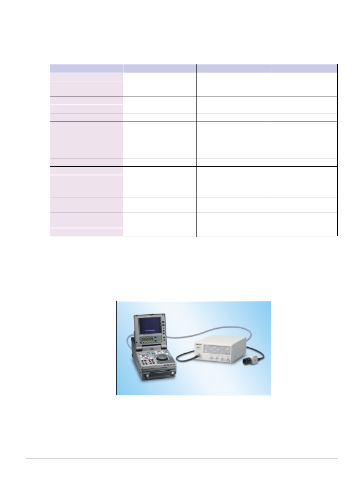
Portable editing recorder
DSR-70A/70AP
Features
• Superb picture quality of the DVCAM format
• Playback capability of DV (SP), DVCAM and DVCPRO-recorded
• Compact, all-in-one package including a 6.4-inch VGALCD monitor,
• Long recording time: up to 184 minutes with a standard-size cassette
• Sequential recording for up to 6 hours
• High-speed picture search over a range of 32 times normal speed, in
• Linear editing by connecting two DSR-70Aunits
• Closed-caption function
• Parallel-run recording
• Two-way power supply system (AC/DC)
*1SDTI (QSDI) and i.LINK (DV) interfaces do not support DVCPRO playback.
1
tapes*
(without a mechanical adaptor)
a full cut-editing controller with a Jog/Shuttle dial and an audio
speaker
and 40 minutes with a mini-size cassette
both forward and reverse
DXC-C33/C33P Product Information Manual –19
Page 22

8. OPTIONAL ACCESSORIES
Cable
Cable
VMC-IL4615/IL4635/IL6615
Features
• i.LINK Cable (1.5/3.5 m) for connecting DXC-C33/C33P to DVCAM
Series
CCMC-9DS
Features
• CCMC-9DS: 5 m, 9-pin D-sub <--> BNCs
(R/G/B/SYNC) and DIN 4-pin (Y/C)
20
Cable
–
DXC-C33/C33P Product Information Manual
CCXC-9DB/9DD
Features
• 5 m, 9-pin D-sub <--> 9-pin D-sub
Page 23

8. OPTIONAL ACCESSORIES
Lenses
Remote control unit
VCL-08WM/16WM/25WM
Features
• 1/3 type C mount
• Focal length: 8 mm (VCL-08WM) / 16 mm (VCL-16WM) /
25 mm (VCL-25WM)
• F number: 1 : 2.2
• Iris: F2.2 to F16
RM-C950
Features
• Full remote control of the camera functions
• Easy control of functions such as Gain, Detail, Master Pedestal and
Red and Blue Gain by turning knobs on the unit
• Power is supplied through the DXC-C33/C33P connected to the
camera adaptor
• Original sheet panel is supplied
• Dimensions (W x H x D): 212 x 41 x 132 mm
• Mass: Approx. 400 g
• Power requirements: DC 12 V
DXC-C33/C33P Product Information Manual –21
Page 24

9. SYSTEM EXAMPLES
3CCD
ExwaveHAD
Monitor
Lens
DXC-C33/C33P
CHU
DXC-C33/C33P
CCU
CCMC-20P05 (5 m)
CCMC-20P10 (10 m)
CCMC-20P30 (30 m)
CCMC-9DS (4BNC&S)
CCXC-9DBS (5BNC)
Basic
9. SYSTEM EXAMPLES
22
–
DXC-C33/C33P Product Information Manual
Page 25

Microscope
Microscope
DXC-C33/C33P
CHU
Microscope
Adapter
Coupler
Monitor
Video Printer
Coaxial Cable
(R, G, B SYNC)
3CCD
ExwaveHAD
CCMC-20P05 (5 m)
CCMC-20P10 (10 m)
CCMC-20P30 (30 m)
DXC-C33/C33P
CCU
Foot Switch
CCMC-9DS
9. SYSTEM EXAMPLES
Note: ‘Sync on Green’ function should be equipped with peripherals.
Please set the ‘SYNC’on the ‘SYSTEM’ sub menu to ‘G’or ‘RGB’
when using the Long-Term exposure function because it is
necessary to output the WEN pulse from the connector for sync.
DXC-C33/C33P Product Information Manual –23
Page 26

9. SYSTEM EXAMPLES
Monitor
3CCD
ExwaveHAD
CCMC-20P05 (5 m)
CCMC-20P10 (10 m)
CCMC-20P30 (30 m)
DXC-C33/C33P
CCU
S-VIDEO
i.LINK Cable
DSR-20MD/20MDP
Surgical Microscope
24
–
DXC-C33/C33P Product Information Manual
Page 27

10. DIMENSIONS
32 40
38
DXC-C33/C33P CCU
10. DIMENSIONS
230
DXC-C33/C33P CHU
200
242
88
7.2
Unit: mm
Unit: mm
DXC-C33/C33P Product Information Manual –25
Page 28

11. TECHNICAL APPENDIX
Pixel
Number
Luminance Level
Pixel
Number
Luminance Level
Pixel
Number
Luminance Level
Pixel
Number
Luminance Level
11. TECHNICAL APPENDIX
DSP
■DynaLatitude
TM
• The DynaLatitude processing function enables you to adjust the contrast of each pixel
according to the luminance signal level of each picture element.
• The DynaLatitude function minimizes video level distortion based on video signal histograms
in order to utilize the limited dynamic range of the standard video signal.
• If there is a dark section and bright section in one image
(i.e. shade and sunshine), then both parts will often look
vague. The DynaLatitude function allows you to adjust
the sharpness of both sections.
• Even when lighting is favorable, more luminance levels
will be allocated to the subject, creating a
clearer, more detailed image.
OFF ON
(Simulated picture)
26
–
DXC-C33/C33P Product Information Manual
Page 29

11. TECHNICAL APPENDIX
Clip level
Knee point
Luminance
level
BGR W BGR BGR W BGR W
Gray Color
Skin Color
Skin Color
without Knee
Skin Color with
conventional
Knee
BGR W
Skin Color
with DCC+
W
100%
90%
70%
High
Low
Normal
Luminance level
Amount of light input to camera
20%
Black Stretch
Knee
Compress
Stretch
■DCC+ process
• The DCC+ (Dynamic Contrast Control Plus) process manages video signal data at three levels -
brightness, hue and saturation. The result is an image with suitable Knee correction and without
hue distortion.
■Knee and Black Stretch
• By adjusting the Knee, a Knee point and Knee slope are set so that the highlighted areas of the
picture can be clearly reproduced.
• Contrast in the dark area of the image can be variably adjusted using the Black Stretch function
for a clear view of specific details.
Electronic Shutter function
• The variable electronic shutter built into the CCD imager enables the DXC-C33/C33P to capture clear
images of moving objects. The shutter speed can be manually selected from a wide range of speeds
(up to 1/100000).
• The Flickerless mode allows you to obtain flickerless
images even in fluorescent lighting conditions.
• The Clearscan
that appear in computer displays when shooting the
display with a conventional video camera.
TM
mode reduces the horizontal bands
<Shutter-speed calculation in Clearscan mode>
Example: When the value is set to 250 H
(NTSC) 250 63.56 us (1 H) + 34.78 us (constant)
= 15924.78 us
= 1/62.8 s
(PAL) 250 64 us (1 H) + 35.6 us (constant)
= 16035.6 us
= 1/62.4 s
DXC-C33/C33P Product Information Manual –27
Page 30

11. TECHNICAL APPENDIX
Long Term Exposure function
• When shooting very dark objects or objects in dark lighting conditions, you can manually set the
shutter speed to 1/60 of a second or more to allow extra light to accumulate on the CCD sensors,
resulting in enhanced sensitivity.
• By Synchronizing the WEN pulse of the camera signal
output with an external memory unit such as a frame
grabber unit/board, it is possible to obtain a still video
<Shutter-speed calculation in LTE mode>
Example: When the value is set to 5 FRM
(NTSC) 5 1/30 = 0.167 s
(PAL) 5 1/25 = 0.2 s
picture.
Versatile white balance
The DXC-C33/C33P has six types of white balance control modes.
a) AWB
The White balance is updated by pushing the WHITE button on the front panel.
b) ATW Normal and ATW Wide
ATW automatically adjusts the white balance in response to varying light conditions. The
DXC-C33/C33P has two ATW modes. Normal mode is effective for a color temperature
range of 2600K to 8000K, and Wide mode adopts wider range of 2400K to 9000K. The
Wide mode is useful under sodium lumps such as those used in traffic surveillance.
In addition, the DXC-C33/C33P has functions that make the area and response speed of
ATW adjustable, as with the AE function.
c) Manual
The white balance can be adjusted manually according to requirements using the Red and
Blue Gain Level.
d) Preset 3200K/5600K
There are two preset white balance modes: one at a color temperature of 3200K and one at
5600K. The 3200K mode is recommended when the camera is used indoors. The 5600K
mode is recommended when the camera is used outdoors during the daytime.
28
–
DXC-C33/C33P Product Information Manual
Page 31

11. TECHNICAL APPENDIX
WEN
Video
On-1 En-1 On En On En On-1 En-1 On-1 En-1En-1
In case of 2 FRM, shutter speed
WEN
Video
OEOEOEOEOEOE
Functions using WEN pulse — Output signal to external frame memory
The DXC-C33/C33P puts out a WEN pulse that enables the external frame memory to minutely
store the video signal output. The timing of the external frame memory can be locked by the HD/VD
signal or the sync signal of the DXC-C33/C33P so that the write-start timing of the external frame
memory can be precisely controlled. In short, the output pulse is effective for the video signal just
after the end of this pulse. The WEN pulse is useful to connect a frame grabber board or video printer
for the Strobe and Long-Term Exposure functions. Using the WEN pulse, users can capture full-frame
still images easily.
Signal specifications of the output pulse
• Output terminal: The 7th pin of the D-sub connector
• Output signal: The polarity of the pulse is switchable, and the signal is 75 ohms, unbalanced.
• Pulse width: 1V(one field)
The DXC-C33/C33P has three pulse modes: WEN-NORM, Strobe and Long term exposure.
1. WEN-NORM mode
The WEN pulse is continuously puts out a high signal in an even field, a low signal in an odd field (see
diagram) or vice versa. This means that the output pulse is a field index pulse.
2. Strobe mode
When the DXC-C33/C33P is set to the Strobe mode, the type of WEN pulse used is WEN-ODD only. The
WEN pulse is useful when used as a trigger for external frame memory to precisely capture full frame.
3. Long-Term exposure mode (WEN-EVEN mode and polarity rising edge)
During the Long-Term exposure mode, the video signal is output, as shown in the diagram below and the
WEN pulse is output in one the field before the valid video field outputs (see diagram). The shutter speed
must be set before the mode is selected.
Note: It is impossible to use both the Strobe mode and the Long-Term exposure mode at the same time.
DXC-C33/C33P Product Information Manual –29
Page 32

12. Q & A
12. Q & A
Q.1
Q.2
Q.3
Q.4
Is it possible to use any cables except the CCMC-20P05/10/30
to connect the CCU with the CHU?
A: No
How many pins does the DV terminal of the DXC-C33/C33P
have?
A: 6 pins. Please use a 6-4 pin/6-6 pin cable to connect DV equipment.
Is it possible to output component signals from the
DXC-C33/C33P?
A: No.
Will camera settings change if you move knob switches when
the camera is locked?
Q.5
Q.6
Q.7
A: No. Knob switches don't work when the camera is locked. It's not until the
lock is released that the camera settings change to the knob positions.
Is it possible to use auto iris control lens?
A: No.
Is it possible to adjust the flange focal length of a lens?
A: No.
What is the dynamic range of the DXC-C33/C33P?
A: The dynamic range is about 300%. The DynaLatitude function is very
useful when shooting an image with both dark and bright areas in a single
picture.
30
–
DXC-C33/C33P Product Information Manual
Page 33

3. Key Features
Distance from lens mount surface must not be more than 4.3 mm
Q.8
Q.9
Is the RS-232C protocol open to the public?
A: Yes. Contact the nearest Sony sales office for more details.
Can lenses other than the optional lenses be used for the
DXC-C33/C33P?
A: There are limitations to the type of C-mount lenses used with the
DXC-C33/C33P. The lens must not project more than 4.3 mm (3/16 inches)
from the lens mount surface. Even if lenses meet this requirement, color
aberration may appear because most C mount lenses on the market are
designed for one CCD, not for 3-CCD, cameras.
DXC-C33/C33P Product Information Manual –31
Page 34

3. Key Features
32
–
DXC-C33/C33P Product Information Manual
Page 35

MK7788V1IW01FEB
©2001 Sony Corporation. All rights reserved.
Reproduction in whole or in part without written permission is prohibited.
Design and specifications are subject to change without notice.
Printed in Japan on recycled paper.
 Loading...