

Page 1
3-205-543-11 (1)
3CCD Color Video Camera
DXC-990/DXC-990P
3CCD Color Video
Camera
Instructions for Use
Instructions d’utilisation
Bedienungsanleitung
Instrucciones de uso
GB
FR
DE
ES
(DXC-990P only)
DXC-990
DXC-990P
© 2001 Sony Corporation
Page 2

Owners Record
The model and serial numbers are located on
the bottom. Record these numbers in the
spaces provided below.
Refer to these numbers whenever you call
upon your Sony dealer regarding this
product.
Model No. Serial No.
WARNING
To prevent fire or shock hazard, do
not expose the unit to rain or
moisture.
To avoid electrical shock, do not
open the cabinet. Refer servicing to
qualified personnel only.
For the customers in the U.S.A.
This equipment has been tested and found to
comply with the limits for a Class A digital
device, pursuant to Part 15 of the FCC
Rules. These limits are designed to provide
reasonable protection against harmful
interference when the equipment is operated
in a commercial environment.
This equipment generates, uses, and can
radiate radio frequency energy and, if not
installed and used in accordance with the
instruction manual, may cause harmful
interference to radio communications.
Operation of this equipment in a residential
area is likely to cause harmful interference in
which case the user will be required to
correct the interference at his own expense.
For the customers in Europe (for
DXC-990P only)
This product with the CE marking complies
with the EMC
Directive (89/336/EEC) issued by the
Commission of the European Community.
Compliance with this directive implies
conformity to the following European
standards:
EN55103-1: Electromagnetic Interference
(Emission)
EN55103-2: Electromagnetic Susceptibility
(Immunity)
This product is intended for use in the
following
Electromagnetic Environment(s):
E1 (residential), E2 (commercial and light
industrial), E3 (urban outdoors) and E4
(controlled EMC environment, ex. TV
studio)
You are cautioned that any changes or
modifications not expressly approved in this
manual could void your authority to operate
this equipment.
The shielded interface cable recommended
in this manual must be used with this
equipment in order to comply with the limits
for digital device pursuant to Subpart B of
Part 15 of FCC Rules.
GB
2
Page 3

Important safeguards/notices for use
in the medical environments
1. All the equipments connected to this unit
shall be certified according to Standard
IEC60601-1, IEC60950, IEC60065 or
other IEC/ISO Standards applicable to
the equipments.
2. When this unit is used together with other
equipment in the patient area*, the
equipment shall be either powered by an
isolation transformer or connected via an
additional protective earth terminal to
system ground unless it is certified
according to Standard IEC60601-1.
* Patient Area
R 1.5 m
Caution
When you dispose of the unit or
accessories, you must obey the law in the
relative area or country and the regulation
in the relative hospital.
IMPORTANT
Nameplate is located on the bottom.
3. The leakage current could increase when
connected to other equipment.
4. This equipment generates, uses, and can
radiate frequency energy. If it is not
installed and used in accordance with the
instruction manual, it may cause
interference to other equipment. If this
unit causes interference (which can be
determined by unplugging the power
cord from the unit), try these measures:
Relocate the unit with respect to the
susceptible equipment. Plug this unit and
the susceptible equipment into different
branch circuit. Consult your dealer.
(According to Standard EN60601-1-2
and CISPR11, Class B, Group 1)
GB
3
Page 4

GB
4
Page 5
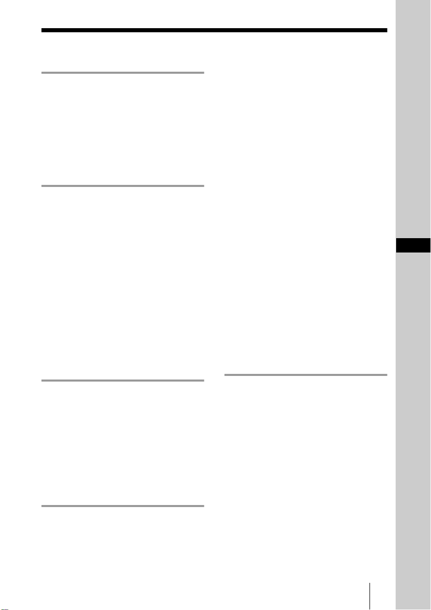
Table of Contents
Overview
Features ..............................................6
Location and Functions of Parts and
Controls ..........................................7
Front Panel/Top Panel ..................7
Rear Panel .....................................7
Adjusting and Setting with
Menus
About On-screen Menus ....................9
Operation through Menus ................10
EXPOSURE Menu ...........................11
CONTRAST Menu ........................145
WHITE BALANCE Menu ...............16
ENHANCER Menu ..........................17
GENERAL Menu .............................18
SYSTEM Menu ................................20
SCENE FILE Menu .........................22
Mounting a Microscope
Adaptor ........................... 27
Mounting on a Tripod ................ 27
Attaching to a Wall or Ceiling ... 27
Connections ..................................... 28
Connecting to Video Equipment
with Composite Video Input
Connectors ...................... 29
Connecting to Video Equipment
with RGB or S-Video
Inputs .............................. 30
Connecting Two or More Cameras
— Multi-Camera
System ............................ 31
Connecting to the CMA-D3/D3CE
Camera Adaptor .............. 32
Connecting to a Remote Control
Unit ................................. 33
Connecting to a Computer ......... 34
Connections for Long Exposure
Shooting .......................... 35
Connections for Shooting Using a
Flash ............................... 36
GB
Operation
Shooting ...........................................23
Basic Shooting Procedure ..........23
Adjusting the Black Balance ......23
Adjusting the White Balance ......24
Adjusting the Picture Tone in a
Multi-Camera System .....25
Installation and
Connections
Installation ........................................26
Mounting the Lens ......................26
Appendix
Precautions ...................................... 37
Typical CCD Phenomena ................ 37
List of Messages .............................. 38
WEN Pulse Timing Chart ................ 39
Specifications .................................. 40
Menu Configuration ........................ 42
5
GB
Page 6

Overview
B
Features
High-quality images
• The high density 1/2 type, three-chip
Exwave HAD
some 380,000 (DXC-990) or 430,000
(DXC-990P) effective picture elements
(pixels), offers superior picture quality:
850 TV lines of high horizontal resolution,
high sensitivity of F11 at 2,000 lx, an
excellent signal-to-noise ratio of 63 dB
(DXC-990) or 62 dB (DXC-990P) and a
low smear level.
• The adoption of the LSI digital signal
processing technology reproduces a finer,
more detailed picture.
• DynaLatitude processing enables you to
adjust contrast finely according to the
luminance signal level of each picture
element.
• The DCC+ (Dynamic Contrast Control
plus) function minimizes the phenomena
whereby the whole screen turns white or a
part of the image becomes colorless when
shooting a very bright object.
• The Partial Enhance function enables you
to adjust the sharpness and tint of only a
specified color.
TM1)
CCD2), containing
controls automatically adjust a wide range of
incoming light levels. The desired AE
window can be set by using the AE AREA
MANUAL function.
Wide range of electronic shutter
modes
The wide range of speeds for the electronic
shutter minimizes blurring in fast-moving
objects and produces acceptably bright still
images of objects shot in poor light.
• Flickerless mode: This mode allows you to
obtain flickerless images shot even under
fluorescent light.
• Clear scan mode: This mode reduces
horizontal bands appearing in computer
displays when shooting the display with
the conventional video camera.
Versatile use with external
equipment
• The video camera is equipped with four
types of outputs: composite, Y/C, RGB
and component outputs. The camera offers
a high-quality picture on a connected
monitor or VCR.
• The camera can be remotely controlled
with the RM-C950 remote control unit
(not supplied).
Wide Range of Exposure Control
The AGC (Auto Gain Control) function and
CCD IRIS
adjust a wide range of incoming light levels.
When the lighting condition is poor, the
AGC function automatically increases the
gain up to 16 times. When incoming light is
excessive, the CCD IRIS function
automatically adjusts shutter speed to cut
exposure to the equivalent of up to 10
aperture stops. When using the video camera
in a fixed location or for a microscope
system, the AGC, CCD IRIS and auto-iris
.....................................................................................................................................................
1) Exwave HADTM: Exwave Hole-Accumulated Diode
2) CCD: Charge-Coupled Device
3) “CCD IRIS
GB
6
TM3)
“Exwave HAD
TM
Features
function automatically
TM
” is a trademark of Sony Corporation.
” is a trademark of Sony Corporation.
RS-232C interface
The camera can be controlled from a
computer via the RS-232C interface.
For details, contact your authorized Sony
dealer.
Compact and lightweight
The camera is compact (70 × 72 × 123.5 mm
7
/8 × 2 7/8 × 4
(2
(approx. 630 g (1 lb 6 oz)), allowing easy
installation even where space is a problem.
7
/8 inches)) and very light
Page 7

Location and Functions of Parts and Controls
1 Boss
Attach the supplied lens mount stopper
to prevent the lens from getting loose.
2 Lens Mount
Attach a zoom lens or microscope
adaptor.
Overview
Front Panel/Top Panel
1
2
3
4
Rear Panel
5
MENU
DC IN/
VBS
BLACK
FILE
SELECT WHITE
LENS
REMOTE
6
7
8
9
0
qa
TRIG IN
RGB/SYNC
VIDEO OUT
BARS
ENTER
MENU LOCK
ON
OFF
GEN LOCK
qs
qd
qf
qg
qh
qj
qk
ql
3 Mount lever
Fasten the lens by turning the mount
lever clockwise after attaching the lens.
4 Installation/tripod holes (top
and bottom panels)
Use these holes when attaching the
camera to a wall or ceiling, or a tripod.
1
″, UNC20)
(screw:
/4
5 TRIG IN connector (BNC type)
Connects to a commercially available
slave unit by converting to BNC type in
strobe mode.
6 RGB/SYNC connector (D-
sub 9-pin)
Outputs RGB signals and their
respective sync signals.
Use the CCXC-9DB/CCXC-9DD/
CCMC-9DS connecting cable for the
connection with the CMA-D2/D2MD/
D2CE/D2MDCE camera adaptor.
For connection with the CMA-D3/
D3CE camera adaptor, use the CCMC3MZ connecting cable.
7 LENS connector (6-pin)
Connects to a lens cable when attaching
the 2/3-inch zoom lens. This connector
is not used for the 1/2-inch zoom lenses.
8 VIDEO OUT connector
(BNC type)
Outputs a composite video signal.
9 DC IN/VBS (DC input/
video signal output) connector
(12-pin)
Connects to the CMA-D2/D2MD/
D2CE/D2MDCE/D3/D3CE camera
adaptor. Inputs the DC power and
outputs the VBS signal.
Location and Functions of Parts and Controls
GB
7
Page 8

q; REMOTE connector (mini
DIN 8-pin)
Connects to the RM-C950 remote
control unit (not supplied).
qa GEN LOCK (reference sync
signal input) connector (BNC
type)
Inputs reference sync signals
synchronized with camera operation.
qs MENU button
Displays the MAIN menu on a monitor
screen. Press again to exit the menu.
When a setting menu is displayed, press
this button to return to the MAIN menu.
For menu operations , se e “Ope r a tion
through Menus” on page 10.
qd
B
/FILE SELECT button
While the menu is displa ye d:
Decreases the setting value or changes
the setting. Also use this button for an
AE window setting, etc.
While the normal screen is displayed:
Switches the user preset file between A
and B.
qf
V
/BLACK (black balance) button
While the menu is displa ye d: Moves
the menu cursor upward. Also use this
button for an AE window setting, etc.
While the normal screen is displayed:
Activates the automatic black balance
adjustment.
qj ENTER button
Selects a setting menu in the MAIN
menu. Also use this button for an AE
window setting, etc.
qk
v
button
Moves the menu cursor downward. Also
use this button for an AE window
setting, etc.
ql MENU LOCK ON/OFF switch
When this switch is set to ON, the menu
is not displayed on the screen even if you
press the MENU button.
qg
b
/ WHITE (white balance)
button
While the menu is displa yed: Increases
the setting value or changes the setting.
Also use this button for an AE window
setting, etc.
While the normal screen is displayed:
Activates the automatic white balance
adjustment when MODE is set to AWB
in WHITE BALANCE menu.
qh BARS (color bars output) button
Outputs the color bar signal. Press again
to revert to video signal output.
For monitor adjust m en t, co ntact your
authorized Sony deale r .
GB
Location and Functions of Parts and Controls
8
Page 9
Adjusting and Setting with Menus
B
About On-screen Menus
Camera operational settings can be changed
through simple adjustment of the settings on
the on-screen menus.
This section explains how to read the onscreen menu before starting menu operation.
For the menu configurat ion of the camera,
see pages 42 and 43.
Note
Before starting menu operation, make sure
that the MENU LOCK ON/OFF switch on
the rear panel is set to OFF. When it is set to
ON, the menu will not be displayed even if
you press the MENU button.
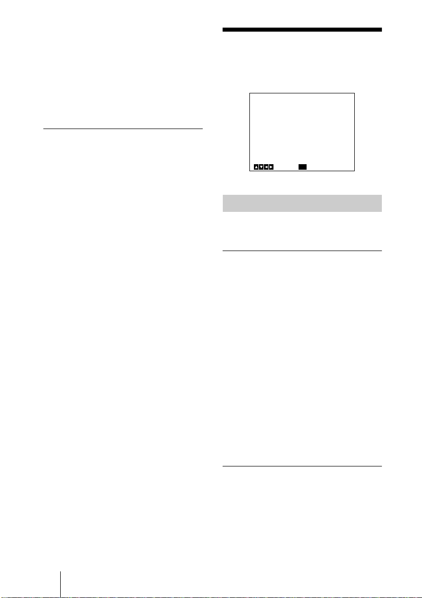
MAIN Menu
CMA
:when the CMA-D3/D3CE camera
adaptor is connected via the CCMC3MZ connecting cable
CMA RM
:when the CMA-D3/D3CE
camera adaptor is connected to the
REMOTE connector on the camera via
the CCMC-3MZ connecting cable, and
the RM-C950 remote control unit is
connected to the REMOTE connector
on the CMA-D3/D3CE
4 User preset file
You can store two types of preset
adjustments into files A and B. Indicates
the currently selected preset file (A or
B).
For details, see “SCENE FILE Menu”
on page 22.
5 Operational message
Indicates how to operate the currently
displayed menu.
Setting Menu
Adjusting and Setting with Menus
ENTER
Next
CMA RM
MENU
[A]
ExitSelect
<MAIN>
>EXPOSURE
CONTRAST
WHITE BALANCE
ENHANCER
GENERAL
SYSTEM
SCENE FILE
1 Cursor
Selects a setting menu or setting item.
Move the cursor up or down using the V
or v button.
2 Setting menu items
When you select the desired item with
the V or v button and press the ENTER
button, the setting menu for adjustment
and setting is displayed.
3 Connecting conditions
The indicator changes according to the
equipment which is connected to the
REMOTE connector on the camera.
RM
:when the RM-C950 remote control
unit is connected
1
<EXPOSURE>
>GAIN
STEP
SHUTTER
2
IRIS
AE LEVEL
5
AE AREA
MENU
CMR RM
[A]
STEP
0dB
OFF
AUTO
+_
MULTI
BackSelect
3
0
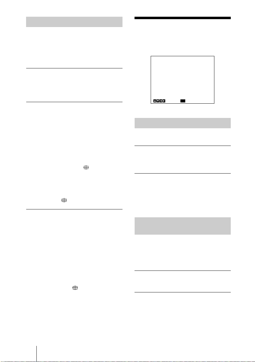
1 Setting menu
Indicates the currently selected setting
menu.
2 Setting items
Indicates the items that can be adjusted
in each setting menu.
Select the item by moving the cursor
beside it with the V or v button.
About On-screen Menus
GB
9
Page 10

3 Set values
The currently set values are displayed.
Change the values using the B or b
button.
For the initial set value on each item, see
“Menu Configuration” on pages 4 2 and
43.
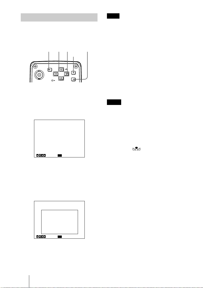
Operation through Menus
To change the settings on the menu, proceed
as follows.
1 4 2,3 2
MENU
TRIG IN
RGB/SYNC
1
Press the MENU button.
The MAIN menu appears.
BLACK
FILE
SELECT WHITE
BARS
ENTER
<MAIN>
>EXPOSURE
CONTRAST
WHITE BALANCE
ENHANCER
GENERAL
SYSTEM
SCENE FILE
ENTER
Next
2
Move the cursor to the menu item to
be set by pressing the
[A]
MENU
ExitSelect
V
or v button,
then press the ENTER button.
The setting menu is displayed.
<EXPOSURE>
>GAIN
STEP
SHUTTER
IRIS
AE LEVEL
AE AREA
MENU
[A]
STEP
0dB
OFF
AUTO
+_
MULTI
BackSelect
0
GB
Operation through Menus
10
Page 11

3
Move the cursor to the item to be
BackSelect
or v button.
V
[A]
STEP
0dB
OFF
AUTO
+_
0
MULTI
adjusted by pressing the
<EXPOSURE>
GAIN
STEP
>SHUTTER
IRIS
AE LEVEL
AE AREA
MENU
4
Change the value by pressing the B or
button.
b
Holding down the button changes the
value quickly.
EXPOSURE Menu
The EXPOSURE menu is used to adjust the
items relating to exposure, such as gain and
shutter mode.
<EXPOSURE>
>GAIN
STEP
SHUTTER
IRIS
AE LEVEL
AE AREA
MENU
[A]
STEP
0dB
OFF
AUTO
+_
0
MULTI
BackSelect
Adjusting and Setting with Menus
<EXPOSURE>
GAIN
STEP
>SHUTTER
SPEED
IRIS
AE LEVEL
AE AREA
MENU
[A]
STEP
0dB
STEP
OFF
AUTO
+_
0
MULTI
BackSelect
To reset to the initial set value
Select the item to be reset, then press the B
and b buttons simultaneously.
For the initial set value on each item, see
“Menu Configuration” on pages 42 and 43.
To return to the normal screen
Press the MENU button while the MAIN
menu is displayed.
While each setting menu is displayed, press
the MENU button to return to the MAIN
menu, then press it again to return to the
normal screen.
GAIN
Adjusts the video gain.
STEP
Select to set the video gain to the desired
level.
STEP
Sets the gain level in the range from 0 to 24
dB.
AGC
Automatically adjusts the gain according to
the brightness of the object to be shot
(Automatic gain control).
LIMIT
Selects the maximum gain level to be
adjusted to 6, 12, 18 or 24 dB.
HYPER
Increases the video gain to about 30 dB.
EXPOSURE Menu
11
GB
Page 12

SHUTTER
Selects the electronic shutter modes.
OFF
Any electronic shutter mode does not
function.
STEP
Select to set the shutter speed to any of 4
steps in long-exposure mode and 11 steps in
high-speed mode.
SPEED
Sets the shutter speed.
To set the shutter speed
1 Select SPEED by pressing the V or v
button.
2 Display OFF by pressing the B and b
buttons simultaneously.
3 Press the B button to set the speed for
long-exposure mode, or press the b button
to set it for high-speed mode.
4 Each press changes the shutter speed.
VARIABLE
Use for fine adjustment of the video output
level in units of 1 frame (long exposure
mode) or in units of 1H (horizontal scanning
time: 63.56
DXC-990P) (clear scan mode).
In long exposure mode, for example, if you
set to 10 frames (about 0.33 seconds), the
video signal produced during this set time is
output in the form of one complete frame at
intervals of about 0.33 seconds. These
pictures, which contain 10 frames of video
information, are much brighter than normal
one-frame images. This mode is useful for
shooting a poorly illuminated object in a
dark place.
The clear scan mode can be used for
shooting computer displays with reduced
horizontal bands appearing across the
display screen. Adjust the value while
observing the noise on the monitor screen so
that you can obtain the image with minimum
noise.
SPEED
Sets the shutter speed.
GB
12
µ
s for DXC-990, 64.00 µs for
EXPOSURE Menu
To set the shutter speed
1 Select SPEED by pressing the V or v
button.
2 Display OFF by pressing the B and b
buttons simultaneously.
3 Press the B button to set the speed for
long-exposure mode, or press the b button
to set it for clear scan mode.
4 Each press changes the shutter speed.
To convert the value into the shutter
speed
Long-exposure mode
Example: When the value is set to 5 frames
5 × 1/30 = 0.1666 seconds (DXC-990)
5 × 1/25 = 0.2000 seconds (DXC-990P)
Clear scan mode
Example: When the value is set to 250H
DXC-990:
µ
250 × 63.56
= 15924.9
s (1H) + 34.9 µs (constant)
µ
s = Approx. 0.016 seconds
DXC-990P:
µ
250 × 64.00
= 16035.0
Note
s (1H) + 35.0 µs (constant)
µ
s = Approx. 0.016 seconds.
Do not use AGC, CCD-IRIS, ATW, AWB
DCC+ and DYNALATITUDE functions in
long exposure mode.
Set the gain level to 0 dB.
CCD-IRIS
Automatically adjusts the luminance level
for optimum output level. When incoming
light is excessive, this function
automatically adjusts the shutter speed to cut
exposure equivalent to up to 10 aperture
stops.
LIMIT
Sets the maximum shutter speed to be
adjusted to 1/250, 1/500, 1/1000, 1/2000,
1/4000, 1/10000, 1/20000,1/40000 or
1/100000.
IRIS
Selects the iris mode.
Page 13
AUTO
Adjusts the iris automatically.
You can set the auto exposure focusing point
and the AE (Auto Exposure) window.
AE LEVEL
Adjusts the auto exposure focusing point in
the range from –127 to +127.
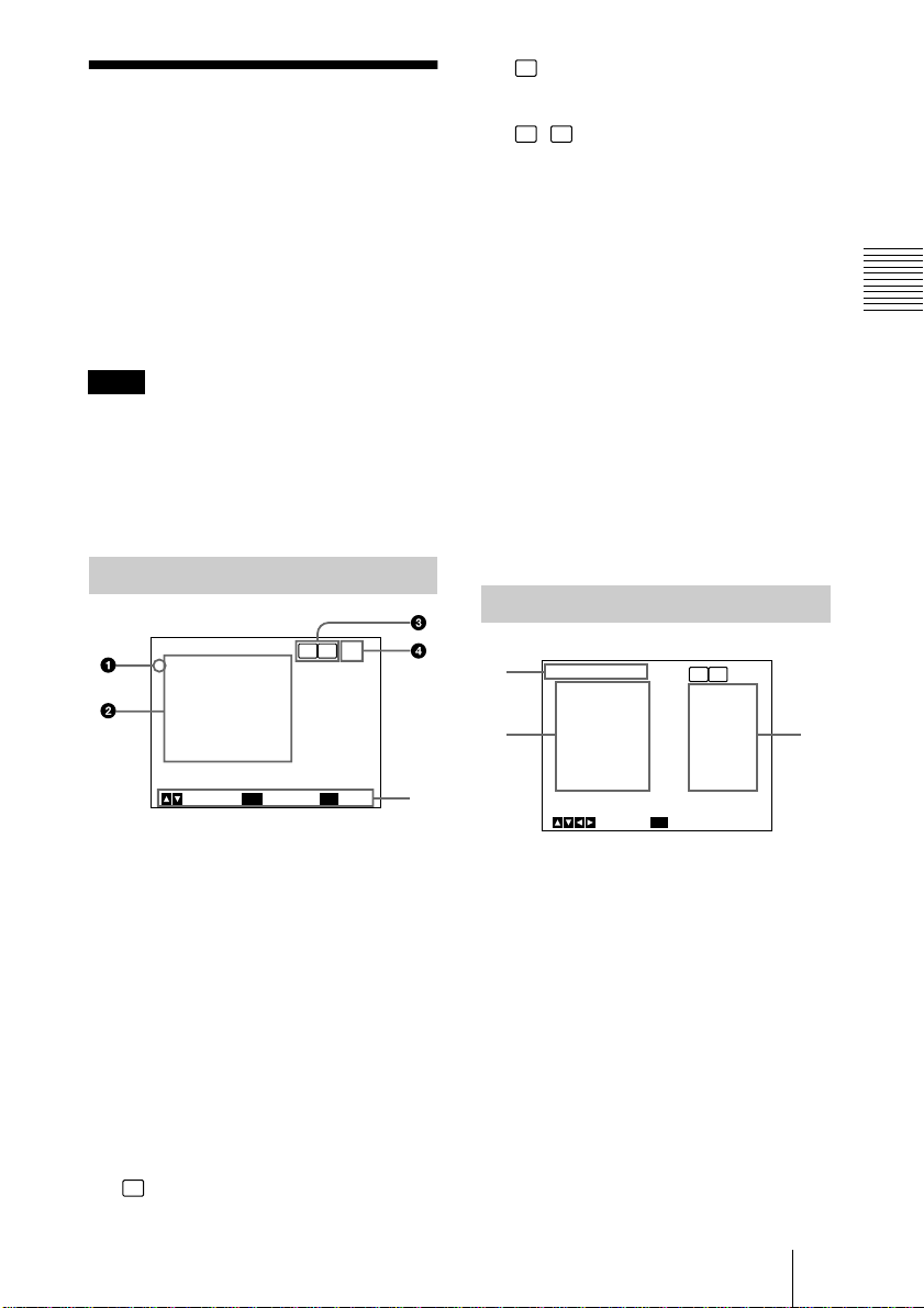
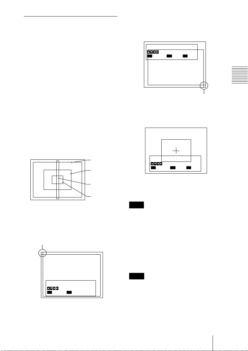
AE AREA
Selects the AE (Auto Exposure) window
when the camera is set to AGC, CCD IRIS or
auto-iris control mode.
MULTI: Divides the screen into 9 sections
and adjusts auto exposure according to the
luminance level in each section. Normally
set to this position.
LARGE, MID, SPOT and SLIT:
Displays the following AE windows and
adjusts auto exposure according to the
luminance level in each area. If the object
you are shooting is very small, you can see
it brighter with this setting to SPOT.
LARGE
MID
2 Move the cross cursor appearing at the
left top corner with the B, b, V or v
button to set the upper and left side size,
then press the ENTER button.
Set Bottom-Right Point
Move Cross Cursor
MENU
Cancel
ENTER
Next
BARS
Back
Cross cursor
3 Move the cross cursor appearing at the
right bottom corner with the B, b, V or
v button to set the lower and right side
size, then press the ENTER button.
Move Window
Move Cross Cursor
MENU
Cancel
ENTER
Fix
BARS
Back
Adjusting and Setting with Menus
SLIT
SPOT
MANUAL: Sets the AE window manually
with the desired size and position on the
screen. Follow the steps below.
1 Select MANUAL and press the ENTER
button.
Cross cursor
Set Top-Left Point
Move Cross Cursor
MENU
Cancel
ENTER
Next
4 Move the AE window to the desired
position with the B, b, V or v button,
then press the ENTER button.
Note
To cancel the setting before completing the
procedure, press the MENU button.
AE SPEED
Appears when you select an option other
than MULTI in AE AREA.
Sets auto exposure focusing speed in AGC,
CCD IRIS or auto-iris control mode. Selects
from MID (normal speed), FAST (fast
speed) and SLOW (slow speed).
Note
If lens hunting occurs, adjust with AE
SPEED.
EXPOSURE Menu
13
GB
Page 14
AE DETECT
Appears when you select an option other
than MULTI in AE AREA.
Selects the detection method of the
luminance level of the selected AE window.
AVERAGE: Selects to detect the average
luminance level of the whole AE window.
PEAK: Selects to detect the part with the
highest luminance level.
MANUAL
Adjusts the iris with the IRIS control on the
RM-C950 remote control unit.
In this option, you can also set the auto
exposure focusing point and the AE (auto
exposure) window. Setting procedure is the
same as that in AUTO.
CONTRAST Menu
The CONTRAST menu is used to adjust the
contrast of the image.
<CONTRAST>
>EFFECT
KNEE POINT
BLACK STRETCH
GAMMA
LEVEL
MASTER PEDESTAL
R. PEDESTAL
B. PEDESTAL
MENU
Select
EFFECT
Selects the setting suitable for the incident
luminance levels.
MANUAL
Selects KNEE POINT setting or BLACK
STRETCH.
KNEE POINT
Sets the knee point according to the
incoming light levels.
OFF: Knee processing does not function.
HIGH: Sets the knee point to the highest
level.
MID: Normally, select this position.
LOW: Sets the knee point to the lowest
level.
Back
[A]
MANUAL
MID
+_
ON
+_
+_
+_
+_
0
0
0
0
0
GB
CONTRAST Menu
14
BLACK STRETCH
Adjusts the luminance of the dark portion of
the screen.
You can set the value within the range from
–10 to +10. The higher the setting, the
brighter the screen.
DCC+
When shooting a very bright object, the
whole screen may white out or a part of the
image may be colorless. This setting
minimizes these phenomena.
Page 15

DYNALATITUDE
Adjusts the contrast according to the
luminance level of each picture element. The
setting is useful for shooting scenes mixed
with bright and dark parts.
You can set the level within the range from
–10 to +10.
GAMMA
Activates gamma compensation.
OFF
Outputs the video signal linearly without
gamma compensation. Use this setting when
you want to produce images for image
processing or image analysis.
ON
Compensates the reproduction
characteristics of a cathode-ray tube of a
monitor to produce natural-tone image.
LEVEL
Adjusts gamma so that you can obtain
natural-tone image. Adjustable range is from
–10 to +10.
R. (red) PEDESTAL, B. (blue)
PEDESTAL
Use these items to finely adjust the pedestal
level of each color. Adjust them while
watching the monitor screen. The items can
be finely adjusted within the range from
–127 to +127.
Adjusting and Setting with Menus
MASTER PEDESTAL
The pedestal levels of the G, B and R output
signals can be adjusted simultaneously.
Adjusts the darkness level of the black part
of the image. Use this function to bring out
details in heavily shaded areas. Use of a
waveform monitor allows easier adjustment.
The adjustable range is from –127 to +127.
The whole screen becomes whiter when you
adjust the level in the direction of +.
The whole screen becomes blacker when
you adjust the level in the direction of –.
Normally set to ±0.
CONTRAST Menu
15
GB
Page 16

WHITE BALANCE Menu
The WHITE BALANCE menu is used to
adjust the white balance.
<WHITE BALANCE>
>MODE
R. PAINT
B. PAINT
AREA
MENU
Select Back
MODE
Selects the white balance modes.
AWB
Select to adjust the white balance
automatically (auto white balance).
R. (red) PAINT, B. (blue) PAINT
Use these items for fine adjustment. Finely
adjusts the red or blue in the range from
–100 to +100. Adjust them while watching
the monitor screen.
For details, see “Adjusting the White
Balance” on page 24.
AREA
A detecting window appears on the monitor
screen. Normally set to NORMAL. If you
want to display the desired window, set to
MANUAL and follow the steps below.
1 Press the ENTER button.
2 Move the left top cross cursor with the B,
b, V or v button to set the upper and left
side size, and press the ENTER button.
3 Move the right bottom cross cursor with
the B, b, V or v button to set the lower and
right side size, and press the ENTER
button.
4 Move the window to the desired position
on the screen with the B, b, V or v button,
and press the ENTER button.
[A]
AWB
+_
+_
NORMAL
0
0
ATW NORMAL/ATW WIDE
Activates auto-tracing white balance. The
white balance is automatically adjusted as
the color temperature changes.
These modes are suitable for shooting when
the light source changes.
Normally, set to ATW NORMAL.
The ATW WIDE setting can cope with a
wider range of color temperature changes.
R. PAINT, B. PAINT
Use these items for fine adjustment. Finely
adjust the red or blue in the range from –10
to +10. Adjust them while watching the
monitor screen.
The adjusted values are stored in memory
separately from AWB values.
AREA
A detecting window appears on the monitor
screen. The setting procedure is the same as
that in AWB.
With NORMAL option, a detecting window
is displayed on the whole screen.
SPEED
Sets the focusing speed. You can select
SLOW (slow speed), MID (normal speed) or
FAST (fast speed).
MANUAL
Use for manual adjustment of white balance.
R. GAIN, B. GAIN
Finely adjusts the red or blue gain in the
range from –127 to +127.
Adjust them while watching the monitor
screen.
3200K
Selects for indoor shooting. (Color
temperature: 3200K)
5600K
Selects for outdoor shooting. (Color
temperature: 5600K)
GB
WHITE BALANCE Menu
16
Page 17

ENHANCER Menu
The ENHANCER menu is used to adjust the
sharpness of the image outline and the color
tone (hue).
OFF
Disables adjustment of the sharpness of the
image outline.
LINEAR MATRIX
<ENHANCER>
>DETAIL
LEVEL
FREQUENCY
LINEAR MATRIX
MODE
MENU
Select Back
[A]
ALL
+_
MID
ALL
STANDARD
0
DETAIL
Enables or disables adjustment of the
sharpness of the image outline.
ALL
Enables adjustment of the sharpness of the
image outline.
LEVEL
Adjusts the level in the range from –127 to
+127.
The lower level decreases the sharpness of
the image outline and makes the image
softer.
The higher level increases the sharpness of
the image outline and makes the image
sharper.
FREQUENCY
Selects the frequency level with which the
image outline is adjusted from LOW (lower
frequency level), MID (middle frequency
level) or HIGH (higher frequency level).
Higher setting provides a sharper outline of
detailed images.
Processes an image with a color matrix to
change the chroma saturation and hue in
order to reproduce natural color.
Adjusting and Setting with Menus
ALL
Corrects the color to reproduce natural color.
MODE
Adjusts the color suitable for the subject.
STANDARD: Normally, select this setting.
R ENHANCE: Enhances the red.
B ENHANCE: Enhances the blue.
G ENHANCE: Enhances the green.
MANUAL: Adjusts each color finely. The
following options appear.
R. PAINT: Finely adjusts the red in the
range from –30 to +30.
G. PAINT: Finely adjusts the green in the
range from –30 to +30.
B. PAINT: Finely adjusts the blue in the
range from –30 to +30.
TARGET
Corrects the color for a specific color.
When you set LINEAR MATRIX to
TARGET, TARGET COLOR appears.
Specify the colors you want to adjust.
OFF
Color correction does not function. Use
when you want to process the image.
TARGET
Adjusts the image outline for a specific
color.
When you set DETAIL to TARGET,
TARGET COLOR appears. Specify the
colors you want to adjust.
ENHANCER Menu
17
GB
Page 18
TARGET COLOR
Select when adjusting DETAIL or LINEAR
MATRIX for a specific color.
This item is displayed only when you set
either DETAIL or LINEAR MATRIX to
TARGET.
ALL
Adjusts DETAIL or LINEAR MATRIX for
the whole image. Normally, set to this
position.
IN
Adjusts DETAIL or LINEAR MATRIX for
a specific color.
RANGE
Finely adjusts the area in the range from –10
to +10.
To specify a color
1 Press the ENTER button.
2 Move the cross cursor ( ) appearing in
the center of the screen to the desired
color with the B, b, V or v button so that
the cross cursor square covers the desired
color, then press the ENTER button.
You can adjust the color indicated by the
cross cursor ( ).
OUT
Adjusts DETAIL or LINEAR MATRIX for
colors other than a specified color.
RANGE
Finely adjusts the area in the range from –10
to +10.
When you select OUT, then set the color
with the procedure in “To specify a color,”
you can adjust DETAIL or LINEAR
MATRIX for colors other than that indicated
by the cross cursor ( ).
GENERAL Menu
The GENERAL menu is used to set the
general items.
<GENERAL>
>CCD MODE
SHADING COMP.
TRIGGER
NEGA
FLICKER CANCELLER
MENU
Select Back
CCD MODE
Selects the CCD read-out mode.
FIELD
Accumulates charges in field units.
Use to shoot a moving object.
FRAME
Accumulates charges in frame units.
Provides the image with the highest possible
vertical resolution. Use to shoot a still
object.
SHADING COMP. (Shading Compensation)
Eliminates green or magenta color which
may appear at the top or bottom of the
screen, when the camera is used with an
optical instrument.
OFF
Color elimination does not function.
ON
If green or magenta color appears at the top
or bottom of the screen when the camera is
attached to a microscope, etc., select this
setting.
[A]
FIELD
OFF
OFF
OFF
OFF
GB
GENERAL Menu
18
Page 19

LEVEL
Adjusts the level within the range from –127
to +127. Adjust while watching the screen so
that the color is eliminated.
+: Green at the top and magenta at the
bottom will be eliminated.
–: Magenta at the top and green at the
bottom will be eliminated.
FLICKER CANCELLER
When using the camera in a 50 Hz lighting
area (DXC-990) or in a 60 Hz lighting area
(DXC-990P), you can obtain images with
less flicker under fluorescent light even
whe n S HU TTER i s s et to CCD IR IS or OF F.
Set this item to OFF when you want to set
NEGA to ON.
TRIGGER
Sets when you use a slave unit connected to
the TRIG IN connector and synchronize the
camera with a stroboscope.
OFF
Select when you do not connect a slave unit.
ON
Select when you connect a slave unit.
POLARITY
Sets to the same polarity as the input pulse
signal.
: Falling edge
: Rising edge
NEGA
Reverses the output image to negative/
positive.
OFF
Outputs the image normally.
OFF
Disables the FLICKER CANCELLER
function.
ON
Reduces flicker under fluorescent light.
Adjusting and Setting with Menus
ON
Outputs the image reversed to negative/
positive.
GENERAL Menu
19
GB
Page 20

SYSTEM Menu
The SYSTEM menu is used to set the items
relating to the system of the camera and
selection of output signals.
<SYSTEM>
>BAUD RATE
D-SUB OUT
D-SUB VIDEO
D-SUB SYNC
RGB SYNC
12P CONNECTOR
MENU
Select Back
BAUD RATE
Switches the baud rate of the REMOTE
connector.
Sets to any of 19200, 9600, 4800, 2400
and 1200.
Set to 9600 when the RM-C950 remote
control unit is connected.
Note
When the CMA-D3/C3CE is connected to
the camera using the CCMC-3MZ
connecting cable, “CMA-D3” will appear
and you cannot select the baud rate.
D-SUB OUT
[A]
9600
R/G/B
VBS
C.SYNC
G
IN
D-SUB SYNC
Selects the sync signal output from the RGB/
SYNC connector (D-sub 9-pin).
C. SYNC
Outputs the composite sync signal.
WEN (WEN 1-3)
Outputs the WEN signal. When connecting
peripheral equipment, the signal is used as
trigger pulse output to the equipment.
Switching WEN 1 to 3 provides a different
pulse signal phase.
For the timing chart of the WEN pulse signal
for each setting, see page 39.
Note
When TRIGGER in the GENERAL menu is
set to OFF, D-SUB SYNC is always set to
WEN and you cannot select a different
phase.
POLARITY
Selects the polarity of the pulse signal.
: Negative
: Positive
Note
When the CMA-D3/C3CE is connected to
the camera with the CCMC-3MZ connecting
cable, you cannot select C. SYNC.
Selects the RGB (R/G/B) or component (Y/
CR/CB) signal output from the RGB/SYNC
connector (D-sub 9-pin).
D-SUB VIDEO
Selects the VBS or Y/C signal output from
the RGB/SYNC connector (D-sub 9pin).
Note
When the CMA-D3/C3CE is connected to
the camera with the CCMC-3MZ connecting
cable, the item does not function.
GB
SYSTEM Menu
20
RGB SYNC
Adds a sync signal to the G signal or R, G
and B signals output from the RGB/SYNC
connector.
OFF
No sync signal is added to an output signal.
G
Adds a sync signal to the G signal output
from the RGB/SYNC connector.
Page 21

RGB
Adds sync signals to the G, B and R signals
output from the RGB/SYNC
connector.
12P CONNECTOR
SC. PHASE ROUGH
Roughly adjusts the subcarrier phase by
setting to 0° or 180°.
SC. PHASE FINE
Finely adjusts the subcarrier phase within
the range from –127 to +127.
Switches the input and output of the DC
IN/VBS connector (12-pin) and selects
the output signal.
IN
Functions as the input connector.
OUT
Functions as the output connector.
SIGNAL
Selects the output signal from the DC
IN/VBS connector.
HD/VD: Outputs the HD/VD signal.
C. SYNC: Outputs the composite sync
signal.
Note
When the CMA-D3/C3CE is connected to
the camera with the CCMC-3MZ connecting
cable, you cannot set this item. Switch
between input and output with the IN/OUT
switch on the CMA-D3/D3CE camera
adaptor.
For details, refer to the operating
instructions of the CMA-D3/D3CE.
When an External Sync Signal (HD/VD Signal) Is Input (HD/VD Lock)
The following item appears.
Adjusts the horizontal phase to synchronize
the camera operation with the reference
signal.
H. PHASE
Adjust the level within the range from –20 to
+127.
Note
Turn on the external sync signal generator
after all equipment is switched on.
Adjusting and Setting with Menus
When an External Sync Signal (VBS Signal) Is Input (VBS Lock)
The following items appear.
Adjusts the horizontal phase and SC
(subcarrier) phase to synchronize the camera
operation with the reference signal.
H. PHASE
Adjusts the horizontal phase within the
range from –20 to +127.
SYSTEM Menu
21
GB
Page 22

SCENE FILE Menu
The SCENE FILE is used to set the preset
menu settings.
The camera has two memory files (A or B)
for storing the menu settings. You can store
a different type of setting into each file, and
switch to the file most suitable for the
shooting conditions quickly. The currently
selected memory file is shown in the upper
right corner of the on-screen menu.
To store the setting
1 Select A or B into which the setting is
stored in the FILE SELECT setting.
2 Press the V or v button to select LOAD.
3 Press the B or b button to select the
desired setting to be stored, and press the
ENTER button.
“Overwrite OK?” appears.
4 Press the ENTER button.
If you do not want to store the setting,
press the MENU button.
<SCENE FILE>
>FILE SELECT
LOAD
Select Back
MENU
[A]
A
FILE SELECT
Selects the file A or B.
LOAD
Selects the setting to be stored into the file
you select with FILE SELECT, and stores
the setting.
STANDARD: Suitable for a camera used as
a permanent fixture.
MICROSCOPE: Suitable for a camera for
a microscope.
FULL AUTO: Automatically adjusts
settings.
STROBE: Suitable for stroboscopic
shooting.
FILE B (or A): When copying the settings
between two files.
GB
SCENE FILE Menu
22
Page 23

Operation
B
Shooting
Basic Shooting Procedure
2
3
1
Turn on the power of the camera and
all connected devices.
2
Illuminate an object with proper
lighting.
4, 5
Adjusting the Black Balance
Adjust the black balance first, after turning
on the power of your camera.
132
MENU
TRIG IN
RGB/SYNC
1
If any menu is displayed on the screen,
press the MENU button to remove it.
2
If a color bar signal is displayed on the
screen, press the BARS button to
remove it.
3
Press the BLACK button.
The lens iris control is automatically
closed, and the black balance is adjusted.
If you use a manual-iris lens, close the
iris then press the BLACK button.
While adjusting, the bars are displayed.
When the adjustment is completed, the
message “BLACK: OK” appears on the
screen.
BLACK
FILE
SELECT WHITE
BARS
ENTER
Operation
3
Aim the camera to the object and
adjust the iris, focus and zoom.
4
Adjust the white balance.
For details, see “Adjusting the White
Balance” on page 24.
5
Adjust the settings as required.
For details, see “Adjusting and Setting
with Menus” on page 9.
6
Start shooting.
Black balance adjustment errors
If the black balance adjustment is not
successful, the message “BLACK: NG”
appears on the screen. If this happens, take
the necessary measures and perform steps 1
through 3 again.
For details, see “List of Messages” on page
38.
Shooting
23
GB
Page 24
Adjusting the White Balance
Each time the lighting condition changes, be
sure to adjust the white balance so that
optimum color reproduction is obtained.
1,3 2 7 2
MENU
TRIG IN
1
Press the MENU button to display the
MAIN menu.
2
Select the WHITE BALANCE menu,
and set MODE to AWB.
<WHITE BALANCE>
>MODE
R. PAINT
B. PAINT
AREA
For menu operation, see “Operation
through Menus ” o n page 10.
3
Select AREA with the V or v button
and then set it to NORMAL with the B
or b button.
A detecting window appears.
<WHITE BALANCE>
MODE
R. PAINT
B. PAINT
>AREA
FILE
SELECT WHITE
RGB/SYNC
Select Back
BLACK
MENU
BARS
button
BARS
ENTER
[A]
AWB
+_
+_
NORMAL
[A]
AWB
+_
+_
NORMAL
0
0
0
0
Note
If a color bar signal is displayed on the
screen, press the BARS button to turn it off.
5
Set the lens iris control as follows:
When using an auto-i ris lens: Set to
auto-iris control.
When using a manual-iris lens: Set to
an appropriate iris opening value.
6
Place a white object (white pattern,
white cloth, etc.) under the same light
condition as that falling on the object
to be shot, then zoom in on the white
object to fill the detecting window on
the screen.
Notes
• Do not include highly reflective objects in
the picture.
• Always shoot the image under suitable
lighting conditions.
7
Press the MENU button twice to
remove the menu.
8
Press the WHITE button.
During adjustment the bars appear. The
message “WHITE: OK” appears on the
screen when the adjustment is done.
The adjusted white level is
automatically stored in memory and
remains even if the power of the camera
is turned off.
To shoot under the same conditions, the
stored white balance is recalled by
setting MODE to AWB in the WHITE
BALANCE menu.
MENU
Select Back
For more details, refer to “WHITE
BALANCE Menu” on page 16.
4
Display the camera image on the
monitor screen.
GB
Shooting
24
Page 25

White balance adjustment errors
If the auto white balance adjustment is not
successful, an error message appears on the
screen. If this happens, take the necessary
measures and perform steps 1 through 8
again.
For more details, see “List of Messages” on
page 38.
WHITE: NG
XXXXX
Error message
Adjusting the Picture Tone in a Multi-Camera System
When configuring a multi-camera system,
adjust all cameras to prevent camera-tocamera variations in picture tone.
Before making the adjustments outlined
below, input the same sync signal to all
cameras.
For connections, see “Connecting Two or
More Cameras — Multi-Camera System” on
page 31.
Connecting the cameras to video
equipment with phase indication
capability
When connecting to a special-effects
generator, a chroma-key unit, or other video
equipment with phase indication capability,
the basic adjustment procedure is as follows:
For more details, see “SYSTEM Menu”
on page 20.
3
Select SC. PHASE from the SYSTEM
menu, and adjust the subcarrier phase.
First adjust the subcarrier phase roughly
with SC. PHASE ROUGH set to 0° and
180°, then adjust it finely using SC.
PHASE FINE.
For more details, refer to the instruction
manual of the connect ed vid eo
equipment with phase indication
capability.
Connecting the cameras to video
equipment without phase
indication capability
Use one of the cameras as a reference
camera and adjust the other cameras to the
reference camera one by one.
1
Adjust the horizontal phase. Select
H. PHASE from the SYSTEM menu,
and adjust so that the reference video
signal and the output signal have the
same horizontal sync phase. Use a
waveform monitor or an oscilloscope
to check the phase.
2
Adjust the subcarrier phase. Select
SC. PHASE from the SYSTEM menu.
First adjust the subcarrier phase roughly
with SC. PHASE ROUGH set to 0° and
180°, then adjust it finely using SC.
PHASE FINE so that the reference video
signal and the output video signal have
the same subcarrier phase. Use a
vectorscope or the wiping function of a
special-effects generator to display the
images of both the reference camera and
the camera to be adjusted
simultaneously on the screen.
Operation
1
Turn on the phase indication
capability of the connected video
equipment.
2
Select H. PHASE from the SYSTEM
menu, and adjust the horizontal phase.
Shooting
25
GB
Page 26

Installation and Connections
B
Installation
Mounting the Lens
Only 1/2-inch bayonet-mount lenses can be
attached to the camera.
For 2/3-inch lenses, an LO-32BMT lens
mount adaptor (not supplied) is required.
Note
After mounting the lens, be sure to attach the
supplied lens mount stopper to prevent the
lens from getting loose.
1
Turn the mount lever
counterclockwise as far as it goes.
(If the lens mount cap is in place, remove
it.)
3
Turn the mount lever clockwise as far
as it goes to lock the lens in the lens
mount.
4
Attach the supplied lens mount
stopper to the boss on the camera.
Lens mount stopper
2
Align the positioning pin on the lens
with the matching hole in the lens
mount and attach the lens (not
supplied).
Lens mount
GB
Installation
26
5
Connect the lens cable to the LENS
connector on the camera.
(This step is not necessary for 1/2-inch
lenses.)
Page 27

Mounting a Microscope Adaptor
To attach the camera to a microscope or an
surgical microscope, it is necessary to attach
an appropriate adaptor.
The mounting procedure is the same as that
of the lenses.
For details, refer to the instruction manual
for an adaptor to be used.
Mounting on a Tripod
To mount the camera on a tripod, use the
screw hole on the bottom or top panel of the
camera.
Use the following screw.
U1/4″, 20 UNC
= 4.5 mm ± 0.2 mm
(ISO standard)
Attaching to a Wall or Ceiling
To attach the camera on a wall or ceiling, use
the appropriate bracket and mounting screws
(U1/4″, 20 UNC).
Installation and Connections
Installation
27
GB
Page 28

Connections
To supply power to the camera, use the
CMA-D2/D2MD/D2CE/D2MDCE/D3/
D3CE camera adaptor (not supplied).
The camera adaptor you can use with your
camera varies with the signal systems and
uses.
System
Use
Medical CMA-
Non-medical CMA-D2
Note
Be sure to turn off the power supply for all
equipment before making any connection.
EIA
standard,
NTSC
color
system
D2MD
CMA-D3
Using the CMA-D2/D2MD/D2CE/
D2MDCE camera adaptor
There are two methods for connecting the
camera and the camera adaptor.
CCIR
standard,
PAL co l or
system
CMAD2MDCE
CMAD2CE
CMAD3CE
Note
Be sure to use one camera adaptor for each
DXC-990/990P unit.
Although the CMA-D2/D2MD/D2CE/
D2MDCE camera adaptor has two
CAMERA connectors (4-pin and 12-pin),
the power consumption of the camera is such
that two camera units cannot be connected at
the same time.
Using the CMA-D3/D3CE camera
adaptor
The connections using the CMA-D3/D3CE
camera adaptor supply power to the camera
and transmit video signals to the camera
adaptor.
For connecting method, see “Connecting to
the CMA-D3/D3CE Camera Adaptor” on
page 32.
Using the CCDC cable
This connection only supplies power to the
camera.
For connecting method, see “Connecting
using the CCDC cable (for supplying power
only)” on page 29.
Using the CCMC cable
This connection supplies power to the
camera and transmits video signals to the
camera adaptor.
For connecting method, see “Connecting
using the CCMC c able (f or supply ing power
to camera and video si gnals to the camera
adapter)” on page 29.
GB
Connections
28
Page 29
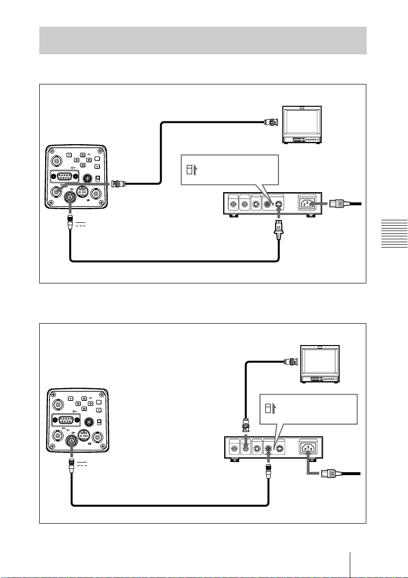
Connecting to Video Equipment with Composite Video Input Connectors
Connecting using the CCDC cable (for supplying power only)
Video monitor,
VCR, etc.
CMA-D2/D2MD/
D2CE/D2MDCE
camera adaptor
CAMERA
(4-pin)
DXC-990/990P
MENU
BLACK
TRIG IN
FILE
SELECT WHITE
RGB/SYNC
LENS
VIDEO OUT
DC IN/
VBS
REMOTE
DC IN/VBS T
ENTER
MENU LOCK
GEN LOCK
BARS
ON
OFF
VIDEO OUT
T
75-ohm coaxial
cable
1
2
Video input
connector
Set the MODE
selector to the [1]
position.
Power
cord
CCDC-5/10/25/50A/100A cable
Connecting using the CCMC cable (for supplying power to camera and
video signals to the camera adapter)
Video monitor,
VCR, etc.
Set the MODE
selector to the [1]
position.
CAMERA
(12-pin)
Power
cord
DXC-990/990P
MENU
BLACK
TRIG IN
FILE
SELECT WHITE
RGB/SYNC
LENS
VIDEO OUT
DC IN/
VBS
REMOTE
BARS
ENTER
MENU LOCK
ON
OFF
GEN LOCK
DC IN/VBS T
CCMC-12P02/05/10/25 cable
75-ohm coaxial
cable
VIDEO
OUT
CMA-D2/D2MD/
D2CE/D2MDCE
camera adaptor
Video input
connector
1
2
Installation and Connections
Connections
29
GB
Page 30

Connecting to Video Equipment with RGB or S-Video Inputs
RGB monitor,
Camera cable: CCXC-9DB (D-sub
9-pin y
CCMC-9DS (D-sub 9-pin
BNC connectors), or
y
BNC, S-video connectors)
R input
G input
B input
image processor,
etc.
DXC-990/990P
MENU
BLACK
TRIG IN
FILE
SELECT WHITE
RGB/SYNC
LENS
VIDEO OUT
DC IN/
VBS
REMOTE
BARS
ENTER
MENU LOCK
GEN LOCK
RGB/SYNC
ON
or
OFF
Camera cable CCXC-9DD
(D-sub 9-pin
y
Sync input
Composite video (BNC)
or S-video input (4-pin)
RGB/SYNC input
D-sub 9-pin)
b)
DC IN/VBS T
Set the MODE
1
selector to the [1]
2
position.
CMA-D2/D2MD/
D2CE/D2MDCE
camera adaptor
CCDC-5/10/25/50A/100A cable or CCMC12P02/05/10/25 cable
a)
CAMERA
(4-pin or 12-pin)
a) If a CCMC cable is used, the S-video signal is also output from the S-video
output of the CMA-D2/D2MD/D2CE/D2MDCE.
b) When using a video monitor without a sync signal input connector, the camera
can be set to output a sync signal with the G signal or RGB signals.
c)
Computer, image
processor etc.
Power
cord
GB
30
For details, se e “SYSTE M Menu” on page 20.
c) This setup is for connecting to a composite video (VBS) connector. To output
separated Y/C signals to the S-video input of video equipment, use a CCMC9DS camera cable.
For details on sw itching cam era outp ut betwee n VBS (co mposite v ideo) and Y /
C, see “SYSTEM Menu” on page 20.
Connections
Page 31

Connecting Two or More Cameras — Multi-Camera System
1
Set the MODE selector to
Sync signal generator
Sync
(VBS or
BS) output
connector
VIDEO
IN
Video input
connector
VBS
OUT
75-ohm coaxial cable
VIDEO
OUT T
VIDEO
IN
Switcher, etc.
VBS OUT
75-ohm coaxial cable
VIDEO
OUT T
DXC-990/990P
MENU
BLACK
TRIG IN
FILE
BARS
SELECT WHITE
ENTER
RGB/SYNC
MENU LOCK
LENS
ON
VIDEO OUT
OFF
DC IN/
GEN LOCK
VBS
REMOTE
DC IN/
VBS T
DXC-990/990P
MENU
BLACK
TRIG IN
FILE
BARS
SELECT WHITE
ENTER
RGB/SYNC
MENU LOCK
LENS
ON
VIDEO OUT
OFF
DC IN/
GEN LOCK
VBS
REMOTE
CMA-D2/
D2MD/D2CE/
D2MDCE
camera
adaptor
GEN LOCK IN
the [1] position.
2
CAMERA
(12-pin)
CCMC-12P02/05/
10/25 cable
1
Set the MODE selector to
the [1] position.
2
CMA-D2/D2MD/
D2CE/D2MDCE
camera adaptor
CAMERA
(12-pin)
GEN LOCK IN
Power
cord
Installation and Connections
Power
cord
Video monitor,
VCR, etc.
DC IN/
VBS T
CCMC-12P02/05/10/25 cable
Notes
• Perform the following to synchronize the picture tone of the cameras when
switching between two or more cameras connected to a video switcher:
-Supply the same sync signal to the GEN LOCK IN connectors on the
cameras.
-Adjust the subcarrier and horizontal synchronization phases for all cameras.
For mo re details, see “Ad justing th e Picture Tone in a Multi-C amer a System ”
on page 25.
• Turn on the power of the sync signal generator after all other equipment is
switched on
.
Connections
31
GB
Page 32

Connecting to the CMA-D3/D3CE Camera Adaptor
DXC-990/990P
MENU
BLACK
TRIG IN
FILE
BARS
SELECT WHITE
ENTER
MENU LOCK
LENS
ON
OFF
DC IN/
GEN LOCK
REMOTE
VIDEO OUT
RGB/SYNC
VBS
Video monitor, VCR, etc.
TRIG IN
RGB/SYNC
REMOTE
DC IN/
VBS T
Video input
connector
75-ohm coaxial
cable
CCMC-3MZ camera cable
CCZZ-1E cable
a)
adaptor
(supplied with the
CCMC-3MZ)
CCZ-A camera cable
(max. 100 m)
26-pin
a)
CAMERA (26-pin)
OUT
CAMERA
RGB
VBS/Y/C
~
DC/AC
AC IN
SELECT
DC15V
IN
REMOTE (front)
R/VBS OUT
G/Y OUT B/C
W.E OUT
TRIG IN HD
VD/SYNC
OUT
R/VBS
IN
OUT
CMA-D3/D3CE
Connecting cable
camera adaptor
(supplied with the
RM-C950)
Power
CAMERA
cord
RM-C950
remote control unit
a) To extend the cable, connect the CCMC-3MZ camera cable to the CCZ-A
camera cable using the cable adaptor supplied with the CCMC-3MZ.
GB
32
Connections
Page 33

Connecting to a Remote Control Unit
75-ohm coaxial cable
CAMERA
Video input
connector
1
2
Video monitor,
VCR, etc.
Set the MODE selector
to the [1] position.
VIDEO OUT T
DXC-990/990P
MENU
BLACK
TRIG IN
FILE
SELECT WHITE
RGB/SYNC
VIDEO OUT
DC IN/
VBS
REMOTE
VBS T
BARS
ENTER
MENU LOCK
LENS
ON
OFF
GEN LOCK
DC IN/
RM-C950
remote control unit
REMOTE
Camera cable
(supplied with RM-C950)
CMA-D2/D2MD/
D2CE/D2MDCE
camera adaptor
CCDC cable: CAMERA (4-pin)
CCMC cable: CAMERA (12-pin)
CCDC-5/10/25/50A/100A cable or
CCMC-12P02/05/10/25 cable
Power
cord
Operating the Camera with the RM-C950 Remote Control Unit
The functions of the following buttons and control on the Remote Control Unit
change as follows, in accordance with the functions of the camera.
Buttons/
control on
the RM-C950
Button/control
names when
used with the
camera
PRINT ENTER Use when displaying the setting menu selected in the
FLASH FILE SELECT Use to switch a preset file between A and B.
LONG
SHUTTER SPEED Use to set the shutter speed without displaying the menu
EXPOSURE
J j
GAIN 2 GAIN Use to change the variable range of gain levels.
FUNCTION
BLACK Use to start the auto black balance adjustment.
J
Function
MAIN menu, or use to set the AE window, etc. manually
in the menus.
when SHUTTER is set to STEP or VARIABLE in the
menu.
Installation and Connections
The sheet for the button names when the camera is used with the remote
control unit is supplied with the camera. Attach the name sheet to the control
panel of the RM-C950.
Connections
33
GB
Page 34

Connecting to a Computer
This section explains the system for controlling the camera with a computer
using an RS-232C command.
75-ohm coaxial cable
VIDEO OUT T
DXC-990/990P
MENU
BLACK
TRIG IN
FILE
BARS
SELECT WHITE
ENTER
MENU LOCK
LENS
ON
REMOTE
OFF
DC IN/
GEN LOCK
REMOTE
DC IN/
VBS T
VIDEO OUT
RGB/SYNC
VBS
Video input
connector
Connecting
cable
Serial interface
connector
Video monitor,
VCR, etc.
a)
Computer
1
Set the MODE selector
to the [1] position.
2
GB
34
CMA-D2/D2MD/D2CE/
D2MDCE camera adaptor
CAMERA
(4-pin or 12-pin)
CCDC-5/10/25/50A/100A cable
or CCMC-12P02/05/10/25 cable
a) Use the shielded connecting cable for connecting to a computer.
For more details on RS-232C protocols and cables for connection to a
computer, contact your authorized Sony dealer.
Connections
Power cord
Page 35

Connections for Long Exposure Shooting
This section explains the system for shooting using long exposure in STEP or
VARIABLE mode for electronic shutter.
1
Set the MODE selector
to the [1] position.
2
Power cord
CMA-D2/D2MD/
D2CE/D2MDCE
camera adaptor
CAMERA
(4-pin or 12-pin)
VBS T
CCDC-5/10/25/50A/100A cable
or CCMC-12P02/05/10/25 cable
DC IN/
DXC-990/990P
MENU
BLACK
TRIG IN
FILE
SELECT WHITE
RGB/SYNC
LENS
VIDEO OUT
DC IN/
VBS
REMOTE
BARS
ENTER
RGB/SYNC
MENU LOCK
ON
OFF
GEN LOCK
Video input
connector
Image processor
or frame memory
unit
CCMC-9DSMN/
CCMC-9DS/
CCXC-9DB
camera cable
External control
connector
Video monitor,
VCR, etc
Installation and Connections
Video output
connector
Video input
connector
Note
When shooting with long exposure, set D-SUB SYNC to WEN1-3 (page 20)
and RGB SYNC to G (when using RGB) (page 20) in the SYSTEM menu.
Connections
35
GB
Page 36

Connections for Shooting Using a Flash
This section explains how to connect a slave unit for synchronizing with a
strobe.
Flash
Video monitor,
VCR, etc.
Video input
connector
Synchronization
cable
TRIG IN
Slave unit
DXC-990/990P
MENU
BLACK
TRIG IN
FILE
BARS
SELECT WHITE
RGB/SYNC
VIDEO OUT
ENTER
MENU LOCK
LENS
DC IN/
GEN LOCK
VBS
REMOTE
DC IN/VBS T
CCDC-5/10/25/50A/
100A cable or
CCMC-12P02/05/10/25
cable
Remote
connector
ON
OFF
RGB/SYNC
1
2
CMA-D2/D2MD/
D2CE/D2MDCE
camera adaptor
Image
processor
Video input connector
CCMC-9DSMN/CCMC-9DS/
CCXC-9DB camera cable
Set the MODE selector
to the [1] position.
CAMERA
(4-pin or 12-pin)
Video output
connector
Power cord
GB
36
Note
When connecting a flash unit, set TRIGGER to ON in the GENERAL menu
(page 19) and D-SUB SYNC to WEN1-3 in the SYSTEM menu (page 20).
Connections
Page 37

Appendix
B
Precautions
Operating or storage location
Operating or storing the camera in the
following locations may cause damage to
the camera:
• Extremely hot or cold places (Operating
°
temperature: –5
°
F])
113
• Exposed in direct sunlight for a long time,
or close to heating equipment (e.g., near
heaters)
• Close to sources of strong magnetism
• Close to sources of powerful
electromagnetic radiation, such as radios
or TV transmitters
• Locations subject to strong vibration or
shock
Ventilation
To prevent heat buildup, do not block air
circulation around the camera.
Transportation
When transporting the camera, repack it as
originally packed at the factory or in
materials equal in quality.
Cleaning
• Use a blower to remove dust from the lens
or optical filter.
• Use a soft, dry cloth to clean the external
surfaces of the camera. Stubborn stains
can be removed using a soft cloth
dampened with a small quantity of
detergent solution, then wipe dry.
• Do not use volatile solvents such as
alcohol, benzene or thinners as they may
damage the surface finishes.
C to +45°C [23°F to
Typical CCD Phenomena
The following phenomena may appear on
the monitor screen while you are using the
DXC-990/990P color video camera. These
phenomena stem from the high sensitivity of
the CCD image sensors, and do not indicate
a fault within the camera.
Vertical smear
A “smear” may appear to extend vertically
from very bright subjects, as shown below.
Video monitor
screen
This phenomenon is common to CCD
imaging elements using an interline transfer
system, and is caused when electric charge
induced by infrared radiation deep within
the photo sensor is transferred to the
resistors.
Aliasing
When shooting fine stripes, straight lines or
similar patterns, the lines may become
slightly jagged.
Blemishes
A CCD image sensor consists of an array of
individual picture elements (pixels). A
malfunctioning sensor element will show up
as a single pixel blemish in the image. This
is generally not a problem.
Pale vertical smear
Very bright subject
(such as an electric
lamp, fluorescent
lamp, sunlight, or
strong reflected light)
Appendix
White speckles
When you shoot a poorly illuminated object
at a high temperature, small white dots may
appear all over the entire screen image.
Precautions/Typical CCD Phenomena
37
GB
Page 38

List of Messages
The following messages may appear on the screen. Take the necessary
measures shown below.
Messages while adjusting the white balance automatically
Message Meaning/remedies
WHITE: OK Automatic white balance adjustment has succeeded.
WHITE: NG
LEVEL LOW
WHITE: NG
LEVEL HIGH
WHITE: NG
TEMP LOW
WHITE: NG
TEMP HIGH
WHITE: NG
TRY AGAIN
The video level of the image is too low.
• Increase the illumination.
• Widen the iris opening.
• Increase the video gain.
Take the measures above, then press the WHITE button.
The video level of the image is too high.
• Remove any brightly illuminated objects.
• Decrease the illumination.
• Close the iris opening.
• Decrease the video gain.
Take the measures above, then press the WHITE button.
Color temperature is too low.
Change the color temperature of the object to the appropriate level.
Color temperature is too high.
Change the color temperature of the object to the appropriate level.
The camera has failed to adjust the white balance. Add white part to the
object shot. Take the measures above, then try again.
If the message appears even if you repeat adjustment, the camera needs to
be checked. Consult your authorized Sony dealer.
Messages while adjusting the black balance automatically
Message Meaning/remedies
BLACK: OK Automatic black balance adjustment has succeeded.
BLACK: NG
IRIS close?
BLACK: NG The camera has failed to adjust the black balance.
GB
List of Messages
38
The camera has failed to adjust the black balance.
Close the iris opening, then press the BLACK button.
Check the camera, then press the BLACK button.
If the message appears even if you repeat adjustment, the inside of the
camera needs to be checked. Consult your authorized Sony dealer.
Page 39

WEN Pulse Timing Chart
The following is the timing charts of a WEN pulse when D-SUB SYNC is set
to WEN 1, 2 or 3 in the SYSTEM menu.
VD
WEN pulse
(WEN 1)
Video signal
ODD EVEN ODD EVEN ODD EVEN ODD EVEN
VD
WEN pulse
(WEN 2)
Video signal
ODD EVEN ODD EVEN ODD EVEN ODD EVEN
Appendix
VD
WEN pulse
(WEN 3)
Video signal
ODD EVEN ODD EVEN ODD EVEN ODD EVEN
WEN Pulse Timing Chart
39
GB
Page 40

Specifications
Charge accumulation mode
Switchable between field and
frame mode
Image system/optical system
Image device 1/2 type CCD, interline transfer
Effective picture elements
Lens mount 1/2-inch bayonet type
type
DXC-990: 768 (horizontal) × 494
(vertical)
DXC-990P: 752 (horizo ntal) × 582
(vertical)
Video system
Synchronization
Signal format
Scanning DXC-990: 525 lines, 2:1 interlace
Scanning frequency
Internal/external synchronization
(VBS, HD/VD), switched
automatically
DXC-990: NTSC standard format
(EIA standard)
DXC-990P: PAL standard format
(CCIR standard)
DXC-990P: 625 lines, 2:1
interlace
DXC-990: 15.734 kHz
(horizontal), 59.94 Hz
(vertical)
DXC-990P: 15.625 kHz
(horizontal), 50.00 Hz (vertical)
Functions/performance
Horizontal resolution
Sensitivity 2000 lux (F11, 3,200K)
Signal-to-noise ratio
Gain control AGC: Automatic Gain Control
White balance AWB: R. PAINT, B. PAINT
Electronic shutter speed
Linear matrix ON/OFF switchable
Gamma compensation
GB
40
850 TV lines
DXC-990: 63 dB
DXC-990P: 62 dB
STEP: 0-24 dB (in units of 1 dB)
HYPER
MANUAL: R. GAIN, B. GAIN
ATW: R. PAINT, B. PAINT
3200K
5600K
Adjustable in the range from 1/
100000 to about 0.5 sec.
(adjustable with CCD IRIS)
ON/OFF switchable
Specifications
Inputs/outputs
Video input/output signals
External sync input
Input/output connectors
Composite video: 1 Vp-p (75
ohms)
R/G/B: 1.0 Vp-p (75 ohms at R/G/
B on Sync)
Y/R-Y/B-Y: 1.0 Vp-p/0.756 Vp-p/
0.756 Vp-p (75 ohms)
Y: 1 Vp-p (75 ohms)
Y/C: 1 Vp-p, same level as VBS
chroma (75 ohms)
SYNC: 2 Vp-p (75 ohms)
VBS/BS, HD/VD
(VBS 1 Vp-p or Burst
0.3 Vp-p, SYNC 0.3 Vp-p or
HD/VD 4.0 Vp-p, 75 ohms)
VIDEO OUT: BNC, 75 ohms,
unbalanced
DC IN/VBS: 12-pin
REMOTE: mini DIN 8-pin
TRIG IN: BNC, TTL
RGB/SYNC: D-sub 9-pin
LENS: 6-pin connector for the 2/3-
inch lenses
General
Power supply 12 V DC
Power consumption
Rated current 0.66 A
Operating temperature
Storage and transport temperature
Operating humidity
Storage and transport humidity
Dimensions 70 × 72 × 123.5 mm (2
Mass Approx. 630 g (1 lb 6 oz)
Supplied accessories
Approx. 7.6 W
–5°C to +45°C (23°F to +113°F)
–20°C to +60°C (–4°F to +140°F)
20% to 80% (free of condensation)
20% to 90% (free of condensation)
× 4 7/8 inches) (w/h/d) (not
including the projecting parts)
Lens mount cap (1)
Lens mount stopper (1)
Name sheet for the buttons on the
RM-C950 (1)
Instructions for Use (1)
Warranty card (1) (DXC-990 only)
Sales companies’ guide (1) (DXC-
990P only)
7
/8 × 2 7/8
Page 41

Medical specifications
Protection against electric shock
Class I
Protection against harmful ingress of water
Ordinary
Degree of safety in the presence of flammable
anesthetics or oxygen
Not suitable for use in the presence
of flammable anesthetics or
oxygen
Mode of operation
Continuous
Design and specifications are subject to
change without notice.
Optional Accessories
Camera cable
CCXC-9DB (D-sub y BNC × 5)
CCXC-9DD (D-sub y D-sub)
CCMC-9DS (D-sub y BNC × 4, S-video
connector)
CCMC-9DSMN (D-sub y BNC × 3, phono
jack, S-video connector)
Dimensions
Front
)
8
/
7
70 (2
7
/8)
Lenses
VCL-707BXM zoom lens (7×)
VCL-714BXEA zoom lens (14×)
VCL-717BXEA zoom lens (17×)
Camera adaptor
CMA-D2 camera adaptor (for NTSC format)
CMA-D2MD camera adaptor (for NTSC format,
medical use)
CMA-D2CE camera adaptor (for PAL format)
CMA-D2MDCE camera adaptor (for PAL format,
medical use)
CMA-D3 camera adaptor (for NTSC format)
CMA-D3CE camera adaptor (for PAL format)
Remote control unit
RM-C950 remote control unit (connecting cable
supplied)
Microscope adaptors and couplers
MVA-40 microscope adaptor
MVA-41A microscope adaptor
MVAC-33-N microscope coupler
MVAC-33-OL microscope coupler
MVAC-33-SM microscope coupler
Power supply cable
CCDC series (length: 5 m [16 ft], 10 m [32 ft], or
25 m [82 ft])
CCDC-A series (length: 50 m [164 ft], or 100 m
[328 ft])
CCMC series (length: 2 m [7 ft], 5 m [16 ft], 10 m
[32 ft], or 25 m [82 ft])
CCMC-3MZ (length: 3 m [10 ft])
CCZ-A series (length: 2 m [7 ft], 5 m [16 ft], 10 m
[32 ft], 25 m [82 ft], 50 m [164 ft] or 100 m
[330 ft])
Side
10.5
7
/16)
(
72 (2
12.7
123.5 (4
7
/8)
1
(
/2)
Appendix
Unit: mm (inches)
Specifications
41
GB
Page 42

Menu Configuration
C
W
B
The menus of the camera are configured as described below.
For detailed information, see pages in parentheses. The initial settings of each
item are bolded.
EXPOSURE GAIN STEP STEP (0 dB)
(Page 11)
SHUTTER OFF
IRIS AUTO AE LEVEL (±0)
ONTRAST EFFECT MANUAL KNEE POINT OFF, HIGH, MID, LOW
(Page 14)
GAMMA OFF
MASTER R. PEDESTAL (±0)
PEDESTAL B. PEDESTAL (±0)
ACG LIMIT (24 dB)
HYPER
STEP SPEED OFF
VARIABLE SPEED OFF
CCD-IRIS LIMIT 1/10000
MANUAL AE AREA MULTI, LARGE, MID,
SPOT, SLIT, MANUAL
AE SPEED MID, FAST, SLOW
AE DETECT AVERAGE, PEAK
BLACK STRETCH (±0)
DCC+
DYNALATITUDE LEVEL (±0)
ON LEVEL (±0)
HITE MODE AWB R. PAINT (±0)
ALANCE B. PAINT (±0)
(Page 16)
ATW NORMAL R. PAINT
ATW WIDE B. PAINT
MANUAL R. GAIN (±0)
GB
Menu Configuration
42
3200K
5600K
AREA (NORMAL)
AREA
SPEED
B. GAIN (±0)
Page 43

ENHANCER DETAIL ALL LEVEL (±0)
(Page 17)
LINEAR ALL MODE MANUAL
MATRIX TARGET STANDARD
TARGET* ALL
COLOR IN RANGE (±0)
TARGET FREQUENCY LOW, MID, HIGH
OFF
OFF R ENHANCE
OUT
* Displayed only when DETAIL or LINEAR MATRIX is set to TARGET.
GENERAL CCD MODE FIELD, FRAME
(Page 18)
SYSTEM BAUD RATE 19200, 9600, 4800, 2400, 1200
(Page 20)
SHADING COMP. OFF
ON LEVEL (±0)
TRIGGER OFF
ON POLARITY ( )
NEGA OFF, ON
FRICKER OFF, ON
CANCELLER
D-SUB OUT R/G/B, Y/CR/CB
D-SUB VIDEO VBS, Y/C
D-SUB SYNC C.SYNC
WEN (WEN 1) POLARITY ( )
WEN 2*
WEN 3*
RGB SYNC OFF, G, RGB
12P CONNECTOR IN
OUT SIGNAL (HD/VD)
H. PHASE** (±0)
SC. PHASE ROUGH** (0˚)
SC. PHASE FINE** (±0)
H. PHASE** (±0)
* Selectable only when TRIGGER is set to ON in the GENERAL menu.
** Displayed only when an external sync signal is input.
B ENHANCE
G ENHANCE
Appendix
SCENE FILE SELECT A, B
FILE LOAD STANDARD, MICROSCOPE, FULL AUTO, STOROBE,
(Page 22)
FILE B
Menu Configuration
43
GB
Page 44

AVERTISSEMENT
Pour éviter tout risque d’incendie ou
d’électrocution, ne pas exposer cet
appareil à la pluie ou à l’humidité.
Pour prévenir tout risque
d’électrocution, ne pas ouvrir le
boîtier. Confier l’entretien de cet
appareil exclusivement à un
personnel qualifié.
Pour les clients européens
(DXC-990P uniquement)
Ce produit portant la marque CE est
conforme à la Directive sur la compatibilité
électromagnétique (EMC) (89/336/CEE)
émise par la Commission de la Communauté
européenne.
La conformité à cette directive implique la
conformité aux normes européennes
suivantes :
• EN55103-1 : Interférences
électromagnétiques (émission)
• EN55103-2 : Sensibilité
électromagnétique (immunité)
Ce produit est prévu pour être utilisé dans les
environnements électromagnétiques
suivants :
E1 (résidentiel), E2 (commercial et industrie
légère), E3 (urbain extérieur) et E4
(environnement EMC contrôlé ex. studio de
télévision).
FR
2
Page 45

Instructions de sécurité importantes
en vue d’une utilisation dans un
environnement médical
1. Tous les équipements raccordés à cet
appareil doivent être agréés suivant les
normes CEI60601-1, CEI60950,
CEI60065 ou les autres normes CEI/ISO
applicables à ces équipements.
2. Si cet appareil est utilisé conjointement
avec d’autres équipements à proximité
d’un patient*, ces équipements doivent
être alimentés par un transformateur
d’isolement ou raccordés à la mise à la
terre du système par une borne de terre de
protection, sauf s’ils sont agréés suivant
la norme CEI60601-1.
* Proximité d’un patient
R 1.5 m
Attention
Lors de l’élimination de l’appareil et de
ses accessoires, vous devez vous
conformer aux dispositions légales en
vigueur dans votre région ou pays ainsi
qu’au règlement de l’hôpital.
3. Dans le cas d’une connexion à d’autres
équipements, le courant de fuite peut
augmenter.
4. Cet appareil génère, utilise et peut
émettre des radiofréquences. S’il n’est
pas installé et utilisé conformément au
mode d’emploi, il peut provoquer des
interférences avec d’autres appareils. Si
cet appareil génère des interférences (ce
que l’on peut facilement contrôler en
débranchant le cordon d’alimentation de
l’appareil), appliquez l’une des mesures
suivantes : Installez cet appareil à un
autre endroit en tenant compte de l’autre
équipement. Branchez cet appareil et
l’autre équipement sur des circuits
d’alimentation différents. Consultez
votre revendeur.
(Conforme aux normes EN60601-1-2 et
CISPR11, Classe B, Groupe 1)
FR
3
Page 46

FR
4
Page 47

Table des matières
Présentation
Caractéristiques ..................................6
Emplacement et fonction des
composants et des commandes .......8
Panneau avant/panneau supérieur 8
Panneau arrière .............................8
Ajustements et réglages à
l’aide des menus
A propos des menus affichés
sur l’écran .....................................10
Pilotage par menus ...........................11
Menu EXPOSURE ...........................12
Menu CONTRAST ..........................15
Menu WHITE BALANCE ...............17
Menu ENHANCER ..........................18
Menu GENERAL .............................20
Menu SYSTEM ................................ 21
Menu SCENE FILE .........................23
Fonctionnement
Prise de vues .....................................25
Procédure de prise de vues
de base .............................25
Réglage de la balance des
noirs .................................25
Réglage de la balance des
blancs ..............................26
Réglage de la tonalité de
l’image dans un
système multicaméra .......27
Installation et raccordement
Installation ....................................... 28
Montage de l’objectif ................. 28
Montage d’un adaptateur
pour microscope ............. 29
Montage sur un trépied .............. 29
Fixation au mur ou au plafond ... 29
Raccordements ................................ 30
Raccordement à un appareil
vidéo équipé de
connecteurs d’entrée
vidéo composites ............ 31
Raccordement à un appareil
vidéo équipé d’entrées
RVB ou S-VIDEO .......... 32
Raccordement de deux caméras
ou plus – Système
multicaméra .................... 33
Connexion de l’adaptateur de
caméra CMA-D3/D3CE . 34
Raccordement d’une
télécommande ................. 35
Raccordement à un ordinateur ... 36
Raccordement pour les prises
de vues à exposition
longue ............................. 37
Raccordement pour les prises
de vues au flash .............. 38
Appendice
Précautions ...................................... 39
Phénomènes typiques du CCD ........ 39
Liste des messages ........................... 40
Chronogramme d’impulsions
WEN ............................................. 41
Spécifications .................................. 42
Configuration du menu .................... 44
FR
FR
5
Page 48

B Présentation
Caractéristiques
Haute qualité d’images
• Le CCD1) Exwave HAD
microprocesseurs, type 1/2 haute densité,
qui contient environ 380.000 (DXC-990)
ou 430.000 (DXC-990P) éléments
d’image effectifs (pixels), offre une
qualité d’image supérieure : 850 lignes TV
de haute résolution horizontale, sensibilité
élevée de F11 à 2.000 lx, excellent rapport
signal/bruit de 63 dB (DXC-990) ou 62 dB
(DXC-990P) et faible niveau de maculage.
• L’adoption de la technologie de traitement
de signal numérique LSI assure la
reproduction d’une image plus finement
détaillée.
• Le traitement DynaLatitude vous permet
de régler le contraste avec précision en
fonction du niveau du signal de luminance
de chaque élément d’image.
• La fonction DCC+ (Dynamic Contrast
Control plus) minimise les phénomènes de
blanchissement de toute la surface de
l’écran et de perte des couleurs d’une
partie de l’image lors des prises de vues de
sujets très lumineux.
• La fonction Partial Enhance vous permet
de régler la netteté et la teinte d’une
couleur spécifique.
Large plage de réglage de
l’exposition
La fonction AGC (Auto Gain Control) et la
fonction CCD IRIS
automatiquement une large plage de niveaux
de lumière entrante. Lorsque les conditions
d’éclairement sont faibles, la fonction AGC
augmente automatiquement le gain (jusqu’à
16 fois). Lorsque la lumière entrante est
excessive, la fonction CCD IRIS règle
TM3)
TM2)
règlent
à trois
automatiquement la vitesse d’obturation
pour couper l’exposition jusqu’à un
équivalent de 10 diaphragmes. Lors de
l’utilisation d’une caméra vidéo dans un
endroit fixe ou pour un système de
microscope, les commandes AGC, CCD
IRIS et de diaphragme automatique règlent
automatiquement une large plage de niveaux
de lumière entrante. La fenêtre AE voulue
peut être réglée à l’aide de la fonction AE
AREA MANUAL.
Large palette de modes
d’obturation électronique
Le large éventail de vitesses pour
l’obturateur électronique minimise le flou
des sujets animés de mouvements rapides et
produit des images fixes d’une luminosité
acceptable d’objets dans des conditions de
faible éclairement.
• Mode de réduction du scintillement : Ce
mode vous permet d’obtenir des images
exemptes de scintillement même sous une
lumière fluorescente.
• Mode d’atténuation de balayage : Ce
mode réduit les bandes horizontales qui
apparaissent sur les écrans d’ordinateurs
lors des prises de vues d’écrans avec la
caméra vidéo classique.
Utilisation polyvalente avec un
appareil externe
• La caméra vidéo est équipée de quatre
types de sorties : composite, Y/C, RVB et
composant. La caméra offre une haute
qualité d’image sur un moniteur ou un
magnétoscope raccordé.
• La caméra peut être commandée à distance
à l’aide d’une télécommande RM-C950
(non fournie).
.....................................................................................................................................................
1) CCD : Dispositif à couplage de charge
2) Exwave HAD
“Exwave HAD
3) “CCD IRISTM” est une marque déposée de Sony Corporation.
FR
6 Caractéristiques
TM
: Exwave Hole-Accumulated Diode
TM
” est une marque déposée de Sony Corporation.
Page 49

Interface RS-232C
La caméra peut être commandée depuis un
ordinateur via l’interface RS-232C.
Pour plus de détails, consultez votre
revendeur Sony agréé.
Compact et légère
La caméra est compacte (70 × 72 ×
123,5 mm (2
7
/8 × 2 7/8 × 4
7
/8 pouces)) et
très légère (environ 630 g (1 lb 6 oz)), ce qui
rend sa pose facile, même dans un espace
réduit.
Présentation
Caractéristiques
FR
7
Page 50

Emplacement et fonction des composants et des commandes
Panneau avant/panneau supérieur
1 Protubérance
Permet de fixer l’arrêt de monture
d’objectif fourni afin d’empêcher que
l’objectif ne se détache.
2 Monture d’objectif
Permet de fixer un objectif zoom ou un
adaptateur de microscope.
3 Levier de monture
Permet de fixer l’objectif en tournant le
levier de monture dans le sens des
aiguilles d’une montre après avoir posé
l’objectif.
1
2
3
4
Panneau arrière
5
MENU
TRIG IN
RGB/SYNC
6
VIDEO OUT
7
8
9
0
qa
VBS
FILE
SELECT WHITE
DC IN/
REMOTE
BLACK
LENS
BARS
ENTER
MENU LOCK
ON
OFF
GEN LOCK
qs
qd
qf
qg
qh
qj
qk
ql
4 Orifices d’installation/trépied
(panneaux supérieur et
inférieur)
Servent à fixer la caméra au mur ou au
plafond ou sur un trépied, (vis : 1/4",
UNC20).
5 Connecteur TRIG IN (type BNC)
Connexion d’un appareil asservi
disponible dans le commerce par
conversion au type BNC en mode
stroboscopique.
6 Connecteur RGB/SYNC
(D-sub à 9 broches)
Sort les signaux RVB et leurs signaux de
synchronisation respectifs.
Utilisez le câble de connexion CCXC9DB/CCXC-9DD/CCMC-9DS pour un
raccordement avec l’adaptateur de
caméra CMA-D2/D2MD/D2CE/
D2MDCE.
Pour un raccordement avec l’adaptateur
de caméra CMA-D3/D3CE, utilisez le
câble de connexion CCMC-3MZ.
7 Connecteur LENS (6 broches)
Connexion d’un câble d’objectif pour la
fixation de l’objectif zoom 2/3 pouces.
Ce connecteur ne s’utilise pas avec les
objectifs zoom 1/2 pouce.
8 Connecteur VIDEO OUT
(type BNC)
Sort un signal vidéo composite.
FR
8 Emplacement et fonction des composants et des commandes
Page 51

9 Connecteur DC IN/
VBS (entrée CC/sortie
signal vidéo) (12 broches)
Connexion de l’adaptateur de caméra
CMA-D2/D2MD/D2CE/D2MDCE/D3/
D3CE. Entre l’alimentation CC et sort le
signal VBS.
q; Connecteur REMOTE
(miniconnecteur DIN à 8
broches)
Connexion d’une télécommande
RM-C950 (non fournie).
qa Connecteur GEN LOCK (entrée
de signal synchro de référence)
(type BNC)
Entre les signaux de synchronisation de
référence synchronisés avec la caméra.
qs Touche MENU
Affiche le menu principal (MAIN) sur
l’écran d’un moniteur. Appuyez de
nouveau sur cette touche pour quitter le
menu. Lorsqu’un paramètre de menu est
affiché, appuyez sur cette touche pour
revenir au menu MAIN.
Pour le fonctionnement du menu, voir
“Pilotage par menus” à la page 11.
qd Touche B/FILE SELECT
Lorsque le menu est affiché : Diminue
la valeur de réglage ou change le
réglage. Utilisez également cette touche
pour le réglage d’une fenêtre AE, etc.
Lorsque l’écran normal est affiché :
Commute les fichiers de réglages
programmés A et B.
qg Touche b/ WHITE (balance
des blancs)
Lorsque le menu est affiché :
Augmente la valeur de réglage ou
change le réglage. Utilisez également
cette touche pour le réglage d’une
fenêtre AE, etc.
Lorsque l’écran normal est affiché :
Active le réglage automatique de la
balance des blancs lorsque MODE est
réglé sur AWB dans le menu WHITE
BALANCE.
qh Touche BARS (sortie des barres
de couleur)
Sort le signal de barres de couleur.
Appuyez de nouveau sur cette touche
pour revenir à la sortie du signal vidéo.
Pour le réglage du moniteur, consultez
votre revendeur Sony agréé.
qj Touche ENTER
Sélection d’un menu de réglage dans le
menu principal (MAIN). Utilisez
également cette touche pour le réglage
d’une fenêtre AE, etc.
qk Touche v
Déplace le curseur du menu vers le bas.
Utilisez également cette touche pour le
réglage d’une fenêtre AE, etc.
ql Commutateur MENU LOCK ON/
OFF
Lorsque ce commutateur est réglé sur
ON, le menu ne s’affiche pas sur l’écran
même si vous appuyez sur la touche
MENU.
Présentation
qf Touche V/BLACK (balance des
noirs)
Lorsque le menu est affiché : Déplace
le curseur du menu vers le haut. Utilisez
également cette touche pour le réglage
d’une fenêtre AE, etc.
Lorsque l’écran normal est affiché :
Active le réglage automatique de la
balance des noirs.
Emplacement et fonction des composants et des commandes
FR
9
Page 52

B Ajustements et réglages à l’aide des menus
3 Conditions de connexion
A propos des menus
L’indicateur change en fonction de
l’équipement raccordé au connecteur
affichés sur l’écran
Les réglages opérationnels de la caméra
peuvent être changés par simple ajustement
des paramètres de réglage des menus
affichés sur écran.
Cette section vous explique comment lire les
menus affichés sur l’écran avant de
commencer à exploiter les menus.
Pour la configuration des menus de la
caméra, voir pages 44 et 45.
REMOTE de la caméra.
RM
: lorsque la télécommande
RM-C950 est raccordée
CMA
: lorsque l’adaptateur de caméra
CMA-D3/D3CE est raccordé à l’aide
du câble de connexion CCMC-3MZ
CMA RM
: lorsque l’adaptateur de caméra
CMA-D3/D3CE est raccordé au
connecteur REMOTE de la caméra à
l’aide du câble de connexion
CCMC-3MZ, et lorsque la
télécommande RM-C950 est
connectée au connecteur REMOTE de
Remarque
Avant de commencer à exploiter les menus,
assurez-vous que le commutateur MENU
LOCK ON/OFF du panneau arrière est réglé
sur OFF. S’il est réglé sur ON, le menu ne
s’affiche pas, même si vous appuyez sur la
touche MENU.
l’appareil CMA-D3/D3CE
4 Fichier de réglages
programmés
Vous pouvez mémoriser deux types de
réglages présélectionnés dans les
fichiers A et B. Indique le fichier de
réglages programmés actuellement
sélectionné (A ou B).
Menu MAIN
Pour tout détail, voir “Menu SCENE
FILE” à la page 23.
ENTER
Next
CMA RM
MENU
[A]
ExitSelect
<MAIN>
>EXPOSURE
CONTRAST
WHITE BALANCE
ENHANCER
GENERAL
SYSTEM
SCENE FILE
1 Curseur
Sélectionne un menu de réglage ou un
paramètre de réglage.
Déplacez le curseur vers le haut ou vers
le bas à l’aide de la touche V ou v.
2 Réglage des paramètres de
menu
Lorsque vous sélectionnez un paramètre
à l’aide de la touche V ou v et que vous
appuyez sur la touche ENTER, le menu
de réglage et d’ajustement de ce
paramètre apparaît.
FR
10 A propos des menus affichés sur l’écran
5 Message opérationnel
Indique comment exploiter le menu
actuellement affiché.
Menu de réglage
5
1
2
<EXPOSURE>
>GAIN
STEP
SHUTTER
IRIS
AE LEVEL
AE AREA
MENU
CMR RM
[A]
STEP
0dB
OFF
AUTO
+_
0
MULTI
BackSelect
1 Menu de réglage
Indique le menu de réglage actuellement
sélectionné.
3
Page 53

2 Paramètres de réglage
Indique les paramètres qui peuvent être
réglés dans chaque menu de réglage.
Sélectionnez un paramètre en plaçant le
curseur en regard à l’aide de la touche
V ou v.
Pilotage par menus
Pour changer les réglages du menu,
procédez comme suit.
3 Valeurs de réglage
Les valeurs de réglage en cours sont
affichées.
Changez les valeurs à l ’aide de la touche
B ou b.
Pour la valeur de réglage initiale de
chaque paramètre, voir “Configuration
du menu” aux pages 44 et 45.
1 4 2,3 2
MENU
TRIG IN
RGB/SYNC
1 Appuyez sur la touche MENU.
Le menu MAIN apparaît.
<MAIN>
>EXPOSURE
CONTRAST
WHITE BALANCE
ENHANCER
GENERAL
SYSTEM
SCENE FILE
2 Déplacez le curseur sur l’élément de
menu à régler en appuyant sur la
V ou v, puis appuyez sur la
touche
touche ENTER.
Le menu de réglage apparaît.
<EXPOSURE>
>GAIN
STEP
SHUTTER
IRIS
AE LEVEL
AE AREA
BLACK
FILE
SELECT WHITE
ENTER
Next
BARS
ENTER
[A]
MENU
ExitSelect
[A]
STEP
0dB
OFF
AUTO
+_
MULTI
0
Ajustements et réglages à l’aide des menus
MENU
BackSelect
Pilotage par menus
11
FR
Page 54

3 Déplacez le curseur sur le paramètre
à régler en appuyant sur la touche
V ou v.
Menu EXPOSURE
<EXPOSURE>
GAIN
STEP
>SHUTTER
IRIS
AE LEVEL
AE AREA
MENU
[A]
STEP
0dB
OFF
AUTO
+_
0
MULTI
BackSelect
4 Changez la valeur en appuyant sur la
B ou b.
touche
Maintenez la touche enfoncée pour
changer la valeur plus rapidement.
<EXPOSURE>
GAIN
STEP
>SHUTTER
SPEED
IRIS
AE LEVEL
AE AREA
MENU
Pour restaurer la valeur de réglage
initiale
Sélectionnez le paramètre à réinitialiser
puis appuyez simultanément sur les touches
B et b.
Pour la valeur de réglage initiale de chaque
paramètre, voir “Configuration du menu”
aux pages 44 et 45.
Pour revenir à l’écran normal
Appuyez sur la touche MENU pendant que
le menu MAIN est affiché.
Lorsqu’un menu de réglage est affiché,
appuyez sur la touche MENU pour revenir
au menu MAIN, puis appuyez de nouveau
sur cette touche pour revenir à l’écran
normal.
[A]
STEP
0dB
STEP
OFF
AUTO
+_
0
MULTI
BackSelect
Le menu EXPOSURE sert à régler les
paramètres relatifs à l’exposition, comme le
gain et le mode d’obturation.
<EXPOSURE>
>GAIN
STEP
SHUTTER
IRIS
AE LEVEL
AE AREA
MENU
[A]
STEP
0dB
OFF
AUTO
+_
0
MULTI
BackSelect
GAIN
Règle le gain vidéo.
STEP
Sélectionner pour régler le gain vidéo au
niveau désiré.
STEP
Règle le niveau de gain dans la plage 0 à
24 dB.
AGC
Règle automatiquement le gain selon la
luminosité de l’objet faisant l’objet de la
prise de vues (commande automatique du
gain).
LIMIT
Sélectionne le niveau de gain maximum à
régler à 6, 12, 18 ou 24 dB.
HYPER
Augmente le gain vidéo à environ 30 dB.
FR
12 Menu EXPOSURE
Page 55

SHUTTER
Sélectionne les modes d’obturation
électronique.
réduisant les bandes horizontales qui
apparaissent au travers de l’écran. Ajustez la
valeur tout en observant le bruit sur l’écran
du moniteur afin d’obtenir l’image avec un
minimum de bruit.
OFF
Aucun mode d’obturation électronique n’est
activé.
STEP
Sélectionner pour régler la vitesse
d’obturation sur l’une des 4 vitesses du
mode d’exposition longue et 11 vitesses du
mode d’exposition à grande vitesse.
SPEED
Règle la vitesse d’obturation.
Réglage de la vitesse d’obturation
1 Sélectionnez SPEED en appuyant sur la
touche V ou v.
2 Affichez OFF en appuyant simultanément
sur les touches B et b.
3 Appuyez sur la touche B pour régler la
vitesse pour le mode d’exposition longue
ou sur la touche b pour la régler pour le
mode d’exposition à haute vitesse.
4 Chaque appui change la vitesse
d’obturation.
VARIABLE
Pour le réglage fin du niveau de sortie vidéo
en unités de 1 photogramme (mode
d’exposition longue) ou de 1H (temps de
balayage horizontal : 63,56
µs pour
DXC-990, 64,00 µs pour DXC-990P)
(mode d’atténuation de balayage).
En mode d’exposition longue par exemple,
si vous la réglez 10 photogrammes (environ
0,33 seconde), le signal vidéo produit durant
cette période est sorti sous la forme d’un
photogramme complet à intervalles
d’environ 0,33 seconde. Ces images, qui
contiennent 10 photogrammes vidéo, sont
beaucoup plus brillantes que des images
normales à un seul photogramme. Ce mode
est très pratique pour les prise de vues
d’objets faiblement éclairés dans des
endroits sombres.
Ce mode peut être utilisé pour réaliser des
prises de vues d’écrans d’ordinateurs en
SPEED
Règle la vitesse d’obturation.
Réglage de la vitesse d’obturation
1 Sélectionnez SPEED en appuyant sur la
touche V ou v.
2 Affichez OFF en appuyant simultanément
sur les touches B et b.
3 Appuyez sur la touche B pour régler la
vitesse pour le mode de longue exposition
ou sur la touche b pour la régler pour le
mode d’atténuation de balayage.
4 Chaque appui change la vitesse
d’obturation.
Conversion de la valeur en vitesse
d’obturation
Mode d’exposition longue
Exemple : Si la valeur est réglée sur 5
photogrammes
5 × 1/30 = 0,1666 seconde (DXC-990)
5 × 1/25 = 0,2000 seconde (DXC-990P)
Mode d’atténuation de balayage
Exemple : Si la valeur est réglée sur 250H
DXC-990 :
250 × 63,56
= 15924,9
µs (1H) + 34,9 µs (constant)
µs = environ 0,016 seconde
DXC-990P :
250 × 64,00
= 16035,0
Remarque
N’utilisez pas les fonctions AGC, CCD-IRIS,
ATW, AWB DCC+ et DYNALATITUDE en
mode d’exposition longue.
Réglez le niveau de gain à 0 dB.
µs (1H) + 35,0 µs (constant)
µs = environ 0,016 seconde.
CCD-IRIS
Réglage automatique du niveau de
luminance pour un niveau de sortie optimal.
Lorsque la lumière entrante est excessive,
cette fonction règle automatiquement la
vitesse d’obturation pour couper
l’exposition jusqu’à un équivalent de
10 diaphragmes.
Ajustements et réglages à l’aide des menus
Menu EXPOSURE
13
FR
Page 56

LIMIT
Règle la vitesse d’obturation maximale à
régler à 1/250, 1/500, 1/1000, 1/2000,
1/4000, 1/10000, 1/20000,1/40000 ou
1/100000.
IRIS
1 Sélectionnez MANUAL puis appuyez
sur la touche ENTER.
Curseur réticulé
Sélectionne le mode de diaphragme.
AUTO
Réglage automatique du diaphragme.
Vous pouvez régler le point de focalisation
d’exposition automatique et la fenêtre
d’exposition automatique AE (Auto
Exposure).
AE LEVEL
Règle le point de focalisation d’exposition
automatique dans la plage –127 à +127.
AE AREA
Sélectionne la fenêtre d’exposition
automatique AE (Auto Exposure) lorsque la
caméra est réglée en mode AGC, CCD IRIS
ou de commande automatique du
diaphragme.
MULTI : Divise l’écran en 9 sections et
règle l’exposition automatique en fonction
du niveau de luminance de chaque section.
En principe, sélectionnez cette position.
LARGE, MID, SPOT et SLIT : Affiche
les fenêtres AE suivantes et règle
l’exposition automatique en fonction du
niveau de luminance de chaque zone. Si
l’objet faisant l’objet de la prise de vues
est très petit, vous pouvez le voir plus clair
si le réglage est sur SPOT.
LARGE
MID
Set Top-Left Point
Move Cross Cursor
MENU
Cancel
ENTER
Next
2 Déplacez le curseur réticulé
apparaissant dans l’angle supérieur
gauche à l’aide des touches B, b, V
ou v pour définir le côté supérieur et
latéral gauche, puis appuyez sur la
touche ENTER.
Set Bottom-Right Point
Move Cross Cursor
MENU
Cancel
ENTER
Next
BARS
Back
Curseur réticulé
3 Déplacez le curseur réticulé
apparaissant dans l’angle inférieur droit
à l’aide des touches B, b, V ou v pour
définir le côté inférieur et latéral droit,
puis appuyez sur la touche ENTER.
Move Window
Move Cross Cursor
MENU
Cancel
ENTER
Fix
BARS
Back
SLIT
SPOT
MANUAL : Règle la fenêtre AE
manuellement avec la taille et la position
désirées sur l’écran. Procédez comme suit.
FR
14 Menu EXPOSURE
4 Déplacez la fenêtre AE à la position
voulue à l’aide des touches B, b, V
ou v, puis appuyez sur la touche
ENTER.
Remarque
Pour annuler le réglage avant la fin de la
procédure, appuyez sur la touche MENU.
Page 57

AE SPEED
S’affiche lorsque vous sélectionnez une
option autre que MULTI dans AE AREA.
Règle la vitesse de focalisation d’exposition
automatique dans les modes AGC, CCD
IRIS ou de réglage automatique du
diaphragme. Sélection de MID (vitesse
normale), FAST (vitesse rapide) ou SLOW
(vitesse lente).
Remarque
En cas d’oscillations de l’objectif, corrigez
avec AE SPEED.
AE DETECT
S’affiche lorsque vous sélectionnez une
option autre que MULTI dans AE AREA.
Sélectionne la méthode de détection du
niveau de luminance de la fenêtre AE
sélectionnée.
AVERAGE : Sélectionne la détection du
niveau moyen de luminance sur toute la
fenêtre AE.
PEAK : Sélectionne la détection de la
zone offrant le niveau de luminance le plus
élevé.
MANUAL
Le réglage du diaphragme s’effectue à l’aide
de la commande IRIS de la télécommande
RM-C950.
Cette option permet aussi de régler le point
de focalisation d’exposition automatique et
la fenêtre d’exposition automatique AE
(auto exposure). La procédure de réglage est
la même que dans AUTO.
Menu CONTRAST
Le menu CONTRAST permet de régler le
contraste de l’image.
<CONTRAST>
>EFFECT
KNEE POINT
BLACK STRETCH
GAMMA
LEVEL
MASTER PEDESTAL
R. PEDESTAL
B. PEDESTAL
MENU
Select
EFFECT
Sélectionne le réglage approprié aux
niveaux de luminance incidente.
MANUAL
Sélectionne le réglage KNEE POINT ou
BLACK STRETCH.
KNEE POINT
Règle le point milieu en fonction du niveau
de lumière entrante.
OFF : Le traitement de point milieu ne
fonctionne pas.
HIGH : Règle le point milieu sur le niveau
le plus élevé.
MID : En principe, sélectionnez cette
position.
LOW : Règle le point milieu sur le niveau
le plus bas.
MANUAL
Back
[A]
MID
+_
ON
+_
+_
+_
+_
0
0
0
0
0
Ajustements et réglages à l’aide des menus
BLACK STRETCH
Ajuste la luminance de la partie foncée de
l’écran.
Vous pouvez régler la valeur dans une plage
comprise entre –10 et +10. Plus la valeur de
réglage est élevée, plus l’écran est lumineux.
DCC+
Lors des prises de vues d’objets très
lumineux, toute la surface de l’écran peut
blanchir ou une partie de l’image perdre ses
couleurs. Ce réglage minimise ces
phénomènes.
Menu CONTRAST
15
FR
Page 58

DYNALATITUDE
Ajuste le contraste en fonction du niveau de
luminance de chaque élément d’image. Ce
réglage s’avère bien pratique lors des prises
de vues de scènes comprenant des zones
d’ombre et des zones de lumière intense.
Vous pouvez régler le niveau dans la plage
–10 à +10.
GAMMA
Active la compensation gamma.
OFF
Sort le signal vidéo de façon linéaire sans
compensation gamma. Utilisez ce réglage
pour produire des images en vue d’une
procédure de traitement d’image ou
d’analyse d’image.
ON
Compense les caractéristiques de
reproduction du tube à rayons cathodiques
d’un moniteur pour produire des images aux
teintes naturelles.
LEVEL
Ajuste gamma pour obtenir une image aux
teintes naturelles. La plage de réglage est
comprise entre –10 et +10.
R. (rouge) PEDESTAL, B. (bleu)
PEDESTAL
Utilisez ces paramètres pour régler avec
précision le niveau de suppression de chaque
couleur. Ajustez-les tout en observant
l’écran du moniteur. Les paramètres peuvent
être réglés précisément dans la plage
–127 à +127.
MASTER PEDESTAL
Les niveaux de suppression des signaux de
sortie R, V et B peuvent être réglés
simultanément.
Ajuste le niveau des zones noires de l’image.
Utilisez cette fonction pour faire ressortir
des détails dans les zones fortement
ombrées. L’utilisation d’un oscilloscope de
contrôle facilite le réglage. La plage de
réglage est –127 à +127.
La totalité de l’écran blanchit lorsque vous
réglez le niveau dans le sens +.
La totalité de l’écran noircit lorsque vous
réglez le niveau dans le sens –.
Le réglage normal est ±0.
FR
16 Menu CONTRAST
Page 59

Menu WHITE BALANCE
4 Déplacez la fenêtre à la position voulue
sur l’écran à l’aide des touches B, b, V
ou v, puis appuyez sur la touche ENTER.
Le menu WHITE BALANCE permet de
régler la balance des blancs.
<WHITE BALANCE>
>MODE
R. PAINT
B. PAINT
AREA
MENU
Select Back
[A]
AWB
+_
+_
NORMAL
0
0
MODE
Sélection des modes de balance des blancs.
AWB
Sélectionnez cette option pour régler
automatiquement la balance des blancs (auto
white balance).
R. (rouge) PAINT, B. (bleu) PAINT
Utilisez ces paramètres pour effectuer un
réglage précis. Règle avec précision le rouge
ou le bleu dans la plage –100 à +100. Réglez
tout en observant l’écran du moniteur.
Pour plus de détails, voir “Réglage de la
balance des blancs” aux pages 26.
AREA
Une fenêtre de détection apparaît sur l’écran
du moniteur. Le réglage normal est
NORMAL. Pour afficher la fenêtre de votre
choix, sélectionnez MANUAL et procédez
comme suit.
1 Appuyez sur la touche ENTER.
2 Déplacez le curseur réticulé supérieur
gauche à l’aide des touches B, b, V ou v
pour définir la taille du côté supérieur et
latéral gauche, puis appuyez sur la touche
ENTER.
3 Déplacez le curseur réticulé inférieur droit
à l’aide des touches B, b, V ou v pour
définir la taille du côté inférieur et latéral
droit, puis appuyez sur la touche ENTER.
ATW NORMAL/ATW WIDE
Active la balance des blancs à suivi
automatique. La balance des blancs est
automatiquement ajustée lorsque la
température des couleurs change.
Ces modes sont pratiques pour les prises de
vue marquées par des changements de
source lumineuse.
En principe, sélectionnez ATW NORMAL.
Le paramètre ATW WIDE est compatible
avec une plus large plage de variations de la
température des couleurs.
R. PAINT, B. PAINT
Utilisez ces paramètres pour effectuer un
réglage précis. Réglez avec précision le
rouge ou le bleu dans la plage –10 à +10.
Réglez tout en observant l’écran du
moniteur.
Les valeurs réglées sont mémorisées
séparément des valeurs AWB.
AREA
Une fenêtre de détection apparaît sur l’écran
du moniteur. La procédure de réglage est la
même que pour AWB.
L’option NORMAL permet d’afficher une
fenêtre de détection sur l’écran complet.
SPEED
Règle la vitesse de focalisation. Vous
pouvez sélectionner SLOW (vitesse lente),
MID (vitesse normale) ou FAST (vitesse
rapide).
MANUAL
Pour le réglage manuel de la balance des
blancs.
R. GAIN, B. GAIN
Réglage précis du gain du rouge ou du bleu
dans une plage comprise entre –127 et +127.
Ajustez-les tout en observant l’écran du
moniteur.
Ajustements et réglages à l’aide des menus
Menu WHITE BALANCE
17
FR
Page 60

3200K
A sélectionner pour les prises de vues en
intérieur. (Température de couleur : 3200K)
5600K
A sélectionner pour les prises de vues en
extérieur. (Température de couleur : 5600K)
Menu ENHANCER
Le menu ENHANCER sert à régler la netteté
des contours de l’image et la tonalité
(teinte).
<ENHANCER>
>DETAIL
LEVEL
FREQUENCY
LINEAR MATRIX
MODE
[A]
ALL
+_
MID
ALL
STANDARD
0
MENU
Select Back
DETAIL
Active ou désactive le réglage de la netteté
des contours de l’image.
ALL
Active le réglage de la netteté des contours
de l’image.
LEVEL
Ajuste le niveau avec précision dans une
plage comprise entre –127 et +127.
Un niveau inférieur diminue la netteté des
contours de l’image et rend l’image plus
douce.
Un niveau supérieur accroît la netteté des
contours de l’image et rend l’image plus
nette.
FREQUENCY
Sélectionne le niveau de la fréquence de
réglage des contours de l’image :
LOW (niveau de fréquence inférieur),
MID (niveau de fréquence moyen) ou
HIGH (niveau de fréquence supérieur).
Une fréquence supérieure accentue la netteté
des contours des images détaillées.
FR
18 Menu ENHANCER
TARGET
Règle les contours de l’image pour une
couleur spécifique.
Si vous réglez DETAIL sur TARGET,
TARGET COLOR apparaît. Spécifiez les
couleurs à régler.
Page 61

OFF
Désactive le réglage de la netteté des
contours de l’image.
LINEAR MATRIX
Traite une image à l’aide d’une matrice de
couleurs pour modifier la saturation des
couleurs et la teinte afin de reproduire des
couleurs naturelles.
ALL
Corrige les couleurs pour reproduire des
couleurs naturelles.
MODE
Règle la couleur appropriée au sujet.
STANDARD : En principe, sélectionnez
cette position.
R ENHANCE : Accentue les rouges.
B ENHANCE : Accentue les bleus.
G ENHANCE : Accentue les verts.
MANUAL : Ajuste chaque couleur avec
précision. Les options suivantes
apparaissent.
R. PAINT : Réglage précis du rouge dans
une plage comprise entre –30 et +30.
G. PAINT : Réglage précis du vert dans
une plage comprise entre –30 et +30.
B. PAINT : Réglage précis du bleu dans
une plage comprise entre –30 et +30.
TARGET COLOR
Sélectionnez ce paramètre lorsque vous
ajustez DETAIL ou LINEAR MATRIX
pour une couleur spécifique.
Ce paramètre ne s’affiche que si vous réglez
DETAIL ou LINEAR MATRIX sur
TARGET.
ALL
Ajuste DETAIL ou LINEAR MATRIX pour
toute l’image. En principe, sélectionnez
cette position.
IN
Ajuste DETAIL ou LINEAR MATRIX pour
une couleur spécifique.
RANGE
Réglage précis de la zone dans une plage
comprise entre –10 et +10.
Pour spécifier une couleur
1 Appuyez sur la touche ENTER.
2 Déplacez le curseur réticulé ( )
apparaissant au centre de l’écran sur la
couleur voulue à l’aide des touches B, b,
V ou v de façon à ce que le carré du
curseur réticulé recouvre la couleur
voulue, puis appuyez sur la touche
ENTER.
Vous pouvez régler la couleur indiquée
par le curseur réticulé ( ).
Ajustements et réglages à l’aide des menus
TARGET
Corrige la couleur pour une couleur
spécifique.
Si vous réglez LINEAR MATRIX sur
TARGET, TARGET COLOR apparaît.
Spécifiez les couleurs à régler.
OFF
La correction des couleurs ne fonctionne
pas. Sélectionnez ce paramètre si vous
voulez traiter l’image.
OUT
Ajuste DETAIL ou LINEAR MATRIX pour
d’autres couleurs qu’une couleur spécifiée.
RANGE
Réglage précis de la zone dans une plage
comprise entre –10 et +10.
Si vous sélectionnez OUT, réglez la couleur
en suivant la procédure dans “Pour spécifier
une couleur”. Vous pouvez régler DETAIL
ou LINEAR MATRIX pour des couleurs
autres que celles indiquées par le curseur
réticulé ( ).
Menu ENHANCER
19
FR
Page 62

Menu GENERAL
Le menu GENERAL permet de définir les
paramètres généraux.
<GENERAL>
>CCD MODE
SHADING COMP.
TRIGGER
NEGA
FLICKER CANCELLER
MENU
Select Back
CCD MODE
Sélectionne le mode de lecture CCD.
FIELD
Accumule des charges en unités de champs.
Utilisez ce paramètre lors des prises de vues
d’objets en mouvement.
FRAME
Accumule des charges en unités de
photogrammes.
Fournit une image offrant la plus haute
résolution verticale possible. Utilisez ce
paramètre lors des prises de vues d’objets
fixes.
[A]
FIELD
OFF
OFF
OFF
OFF
la caméra est installée sur un microscope,
etc., sélectionnez ce paramètre.
LEVEL
Ajuste le niveau dans la plage –127 à +127.
Ajustez tout en observant l’écran pour
éliminer la couleur.
+: Le vert dans le haut de l’écran et le
magenta dans le bas sont éliminés.
– : Le magenta dans le haut de l’écran et le
vert dans le bas sont éliminés.
TRIGGER
Sélectionnez ce paramètre lorsque vous
utilisez un appareil asservi raccordé via le
connecteur TRIG IN et que vous
synchronisez la caméra avec un stroboscope.
OFF
Sélectionnez ce paramètre si vous ne
raccordez pas un appareil asservi.
ON
Sélectionnez ce paramètre si vous raccordez
un appareil asservi.
POLARITY
Règle sur la même polarité que le signal
d’impulsion d’entrée.
: Front de descente
: Front de montée
SHADING COMP. (Compensation de l’ombrage)
Elimine la couleur verte ou magenta qui peut
apparaître dans le haut ou dans le bas de
l’écran lorsque la caméra est employée avec
un instrument optique.
OFF
L’élimination des couleurs ne fonctionne
pas.
ON
Si une couleur verte ou magenta apparaît
dans le haut ou dans le bas de l’écran lorsque
FR
20 Menu GENERAL
NEGA
Inverse l’image sortie en négatif/positif.
OFF
Sort l’image normalement.
ON
Sort l’image inversée en négatif/positif.
Page 63

FLICKER CANCELLER
Lorsque vous utilisez la caméra dans une
zone à éclairement de 50 Hz (DXC-990) ou
de 60 Hz (DXC-990P), vous pouvez obtenir
des images avec moins de scintillements
sous lumière fluorescente même si
SHUTTER est réglé sur CCD IRIS ou OFF.
Réglez ce paramètre sur OFF lorsque vous
voulez régler NEGA sur ON.
OFF
Désactive la fonction FLICKER
CANCELLER.
ON
Réduit le scintillement sous lumière
fluorescente.
Menu SYSTEM
Le menu SYSTEM sert à régler les
paramètres relatifs au système de la caméra
et la sélection des signaux de sortie.
<SYSTEM>
>BAUD RATE
D-SUB OUT
D-SUB VIDEO
D-SUB SYNC
RGB SYNC
12P CONNECTOR
MENU
Select Back
BAUD RATE
Change le débit en bauds du connecteur
REMOTE .
Sélectionnez 19200, 9600, 4800, 2400
ou 1200.
Choisissez 9600 si la télécommande
RM-C950 est raccordée.
Remarque
Lorsque l’appareil CMA-D3/C3CE est
raccordé à la caméra en utilisant le câble de
connexion CCMC-3MZ, CMA-D3
apparaîtra et vous pourrez sélectionner le
débit en bauds.
[A]
9600
R/G/B
VBS
C.SYNC
G
IN
Ajustements et réglages à l’aide des menus
D-SUB OUT
Sélectionne la sortie du signal RVB (R/G/B)
ou composant (Y/CR/CB) via le connecteur
RGB/SYNC (D-sub à 9 broches).
D-SUB VIDEO
Sélectionne la sortie du signal VBS ou Y/C
via le connecteur RGB/SYNC (D-sub
à 9 broches).
Remarque
Lorsque l’appareil CMA-D3/C3CE est
raccordé à la caméra en utilisant le câble de
connexion CCMC-3MZ, le paramètre ne
fonctionne pas.
Menu SYSTEM
21
FR
Page 64

D-SUB SYNC
Commute la sortie du signal de
synchronisation via le connecteur RGB/
SYNC (D-sub à 9 broches).
C. SYNC
Sort le signal de synchronisation composite.
WEN (WEN 1-3)
Sort le signal WEN. Si vous raccordez un
appareil périphérique, le signal est utilisé
comme impulsion de déclenchement
envoyée vers l’appareil.
La commutation de WEN 1 à 3 fournit une
phase de signal d’impulsion différente.
G
Ajoute un signal de synchronisation au
signal V sorti via le connecteur RGB/SYNC
.
RGB
Ajoute des signauxde synchronisation aux
signaux R, V et B sortis via le connecteur
RGB/SYNC .
12P CONNECTOR
Commute l’entrée et la sortie du connecteur
DC IN/VBS (12 broches) et
sélectionne le signal de sortie.
Pour le chronogramme du signal
d’impulsion WEN pour chaque réglage, voir
page 41.
Remarque
Lorsque le paramètre TRIGGER du menu
GENERAL est réglé sur OFF, D-SUB
SYNC est toujours réglé sur WEN et vous ne
pouvez pas sélectionner une autre phase.
POLARITY
Sélectionne la polarité du signal
d’impulsion.
: Négative
: Positive
Remarque
Si l’appareil CMA-D3/C3CE est raccordé à
la caméra par l’intermédiaire du câble de
connexion CCMC-3MZ, vous ne pouve z pas
sélectionner C. SYNC.
RGB SYNC
Ajoute un signal de synchronisation au
signal V ou aux signaux R, V et B sortis via
le connecteur RGB/SYNC .
IN
Sert de connecteur d’entrée.
OUT
Sert de connecteur de sortie.
SIGNAL
Sélectionne le signal de sortie via le
connecteur DC IN/VBS .
HD/VD : Sort le signal HD/VD.
C. SYNC : Sort le signal de
synchronisation composite.
Remarque
Lorsque l’appareil CMA-D3/C3CE est
raccordé à la caméra en utilisant le câble de
connexion CCMC-3MZ, il n’est pas
possible de régler cet paramètre. Commute
entre l’entrée et la sortie à l’aide du
commutateur IN/OUT de l’adaptateur de
caméra CMA-D3/D3CE.
Pour obtenir plus de détails, reportez-vous
au mode d’emploi de l’appareil CMA-D3/
D3CE.
OFF
Aucun signal de synchronisation n’est ajouté
aux signaux de sortie.
FR
22 Menu SYSTEM
Page 65

Lorsqu’un signal de synchronisation externe (Signal VBS) est entré (Verrouillage VBS)
Les paramètres suivants apparaissent.
Ajuste la phase horizontale et la phase SC
(sous-porteuse) pour synchroniser le
fonctionnement de la caméra avec le signal
de référence.
H. PHASE
Ajuste la phase horizontale dans une plage
comprise entre –20 et +127.
Menu SCENE FILE
Le menu SCENE FILE sert à régler les
paramètres de menu présélectionnés.
La caméra comprend deux fichiers de
mémoire (A et B) pour la mémorisation des
paramètres de menu. Vous pouvez
mémoriser un type de paramètre différent
dans chaque fichier et commuter rapidement
le fichier le mieux approprié aux conditions
de prise de vues. Le fichier de mémoire
actuellement sélectionné est indiqué dans
l’angle supérieur droit du menu affiché.
Ajustements et réglages à l’aide des menus
SC. PHASE ROUGH
Ajuste grossièrement la phase de sousporteuse en la réglant sur 0° ou 180°.
SC. PHASE FINE
Règle avec précision la phase de sousporteuse dans une plage comprise entre –127
et +127.
Lorsqu’un signal de synchronisation externe (Signal HD/VD) est entré (Verrouillage HD/VD)
Le paramètre suivant apparaît.
Ajuste la phase horizontale pour
synchroniser le fonctionnement de la caméra
avec le signal de référence.
H. PHASE
Ajuste le niveau dans une plage comprise
entre –20 et +127.
Remarque
Active le générateur de signaux de
synchronisation externes après la mise sous
tension de la totalité de l’équipement.
<SCENE FILE>
>FILE SELECT
LOAD
Select Back
MENU
[A]
A
FILE SELECT
Sélectionne le fichier A ou B.
LOAD
Règle le paramètre à mémoriser dans le
fichier que vous sélectionnez avec FILE
SELECT et mémorise le paramètre.
STANDARD : Convient à une caméra
utilisée comme système permanent.
MICROSCOPE : Convient à une caméra
pour microscope.
FULL AUTO : Ajuste automatiquement les
paramètres.
STROBE : Convient à une prise de vues
stroboscopique.
FILE B (ou A) : Pour copier des paramètres
entre deux fichiers.
Menu SCENE FILE
23
FR
Page 66

Pour mémoriser le paramètre
1 Sélectionnez A ou B suivant le fichier
dans lequel le réglage est mémorisé dans
le paramètre FILE SELECT.
2 Appuyez sur la touche V ou v pour
sélectionner LOAD.
3 Appuyez sur la touche B ou b pour
sélectionner le réglage à mémoriser, puis
appuyez sur la touche ENTER.
L’indication “Overwrite OK?” apparaît.
4 Appuyez sur la touche ENTER.
Si vous ne souhaitez pas mémoriser le
réglage, appuyez sur la touche MENU.
FR
24 Menu SCENE FILE
Page 67

B Fonctionnement
Prise de vues
Procédure de prise de vues de base
2
3
1 Mettez la caméra et tous les appareils
connectés sous tension.
2 Eclairez un objet de manière
appropriée.
3 Dirigez la caméra vers l’objet et réglez
le diaphragme, la mise au point et le
zoom.
4 Réglez la balance des blancs.
Pour tous détails, voir “Réglage de la
balance des blancs” à la page 26.
5 Réglez les paramètres.
Pour tous détails, voir “Ajustements et
réglages à l’aide des menus” à la
page 10.
4, 5
Réglage de la balance des noirs
Réglez la balance des noirs en premier après
avoir mis la caméra sous tension.
132
MENU
TRIG IN
RGB/SYNC
1 Si un menu est affiché sur l’écran,
appuyez sur la touche MENU pour le
désactiver.
2 Si un signal de barres de couleur est
affiché sur l’écran, appuyez sur la
touche BARS pour le désactiver.
3 Appuyez sur la touche BLACK.
Le diaphragme de l’objectif se ferme
automatiquement et la balance des noirs
est réglée. Si vous utilisez un objectif à
réglage manuel du diaphragme, fermez
le diaphragme puis appuyez sur la
touche BLACK.
Pendant le réglage, les barres
s’affichent. Lorsque le réglage est
terminé, le message “BLACK: OK”
apparaît sur l’écran.
Erreurs de réglage de la balance des
noirs
Si le réglage de la balance des noirs échoue,
le message “BLACK: NG” apparaît sur
l’écran. Si cela se produit, prenez les
mesures requises et recommencez les étapes
1 à 3.
Pour tous détails, voir “Liste des messages”
à la page 40.
BLACK
FILE
SELECT WHITE
BARS
ENTER
Fonctionnement
6 Commencez la prise de vues.
Prise de vues
25
FR
Page 68

Réglage de la balance des blancs
Chaque fois que les conditions d’éclairage
changent, n’oubliez pas de régler la balance
des blancs de manière à obtenir une
reproduction optimale des couleurs.
4 Affichez l’image de la caméra sur
l’écran du moniteur.
Remarque
Si le signal de barres de couleur est affiché
sur l’écran, appuyez sur la touche BARS
pour le désactiver.
1,3 2 7 2
MENU
TRIG IN
RGB/SYNC
FILE
SELECT WHITE
BLACK
Touche
BARS
BARS
ENTER
1 Appuyez sur la touche MENU pour
afficher le menu MAIN.
2 Sélectionnez le menu WHITE
BALANCE et réglez MODE sur
AWB.
<WHITE BALANCE>
>MODE
R. PAINT
B. PAINT
AREA
MENU
Select Back
[A]
AWB
+_
+_
NORMAL
0
0
Pour le fonctionnement du menu, voir
“Pilotage par menus” à la page 11.
3 Sélectionnez AREA avec la touche V
ou v puis réglez-le sur NORMAL à
l’aide de la touche B ou b.
Une fenêtre de détection apparaît.
<WHITE BALANCE>
MODE
R. PAINT
B. PAINT
>AREA
MENU
Select Back
Pour plus de détails, voir “Menu
WHITE BALANCE” à la page 17.
[A]
AWB
+_
+_
NORMAL
0
0
5 Réglez la commande de diaphragme
de l’objectif comme suit :
Si vous utilisez un objectif à réglage
automatique du diaphragme :
Réglez-la sur la position de réglage
automatique.
Si vous utilisez un objectif à réglage
manuel du diaphragme : Sélectionnez
une ouverture de diaphragme
appropriée.
6 Placez un objet blanc (motif blanc,
vêtement blanc, etc.) dans les mêmes
conditions d’éclairage que celles de
l’objet faisant l’objet de la prise de
vue, puis faites un zoom sur l’objet
blanc pour remplir la fenêtre de
détection sur l’écran.
Remarques
• N’incluez pas d’objets très réfléchissants
dans l’image.
• Réalisez toujours les prises de vues dans
des conditions d’éclairage appropriées.
7 Appuyez deux fois sur la touche
MENU pour désactiver le menu.
8 Appuyez sur la touche WHITE.
Pendant le réglage, les barres
apparaissent. Le message
“WHITE: OK” apparaît sur l’écran
lorsque le réglage est terminé.
Le niveau de blanc réglé est
automatiquement enregistré dans la
mémoire et reste mémorisé même après
que la caméra a été mise hors tension.
Pour réaliser une prise de vues dans les
mêmes conditions, la balance des blancs
mémorisée est rappelée en réglant
MODE sur AWB dans le menu WHITE
BALANCE.
FR
26 Prise de vues
Page 69

Erreurs de réglage de la balance des
blancs
Si le réglage de la balance des blancs
échoue, un message d’erreur apparaît sur
l’écran. Si cela se produit, prenez les
mesures requises et recommencez les étapes
1 à 8.
Pour plus de détails, voir “Liste des
messages” à la page 40.
WHITE: NG
XXXXX
Message d’erreur
Réglage de la tonalité de l’image dans un système multicaméra
Lors de la configuration d’un système
multicaméra, réglez toutes les caméras afin
d’éviter des variations de la tonalité de
l’image d’une caméra à une autre.
Avant de procéder aux réglages décrits
ci-après, envoyez le même signal de
synchronisation à toutes les caméras.
Pour les connexions, voir “Raccordement
de deux caméras ou plus – Système
multicaméra” à la page 33.
Raccordement de caméras à un
appareil vidéo à indication de
phase
Pour raccorder un générateur d’effets
spéciaux, une unité chromatique ou un autre
appareil vidéo à indication de phase,
appliquez la procédure de réglage de base
suivante :
1 Activez la fonction d’indication de
phase de l’appareil vidéo connecté.
2 Sélectionnez H. PHASE dans le menu
SYSTEM et réglez la phase
horizontale.
Pour plus de détails, voir “Menu
SYSTEM” à la page 21.
3 Sélectionnez SC. PHASE dans le
menu SYSTEM et réglez la phase de
sous-porteuse.
Ajustez d’abord grossièrement la phase
de sous-porteuse avec SC. PHASE
ROUGH sur 0° et 180°, puis réglez avec
précision à l’aide de SC. PHASE FINE.
Pour plus de détails, reportez-vous au
mode d’emploi de l’appareil vidéo
connecté à indication de phase.
Fonctionnement
Raccordement de caméras à un
appareil vidéo sans indication de
phase
Utilisez l’une des caméras comme caméra
de référence et ajustez les autres caméras
une par une suivant la caméra de référence.
1 Ajustez la phase horizontale.
Sélectionnez le paramètre H. PHASE
dans le menu SYSTEM et ajustez-le
de façon à ce que le signal vidéo de
référence et le signal de sortie aient la
même phase de synchronisation
horizontale. Utilisez un oscilloscope
de contrôle ou un oscilloscope pour
contrôler la phase.
2 Ajustez la phase de sous-porteuse.
Sélectionnez SC. PHASE dans le
menu SYSTEM.
Ajustez d’abord grossièrement la phase
de sous-porteuse avec SC. PHASE
ROUGH sur 0° et 180°, puis réglez avec
précision à l’aide de SC. PHASE FINE
de façon à ce que le signal vidéo de
référence et le signal vidéo de sortie
aient la même phase de sous-porteuse.
Utilisez un vecteurscope ou la fonction
d’effacement d’un générateur d’effets
spéciaux pour afficher simultanément
sur l’écran l’image de la caméra de
référence et de la caméra à régler.
Prise de vues
27
FR
Page 70

B Installation et raccordement
Installation
Montage de l’objectif
Ne poser que des objectifs à monture
baïonnette 1/2 pouce sur la caméra.
Pour les objectifs 2/3 pouce, utiliser un
adaptateur de monture d’objectif
LO-32BMT (non fourni).
Remarque
Après le montage de l’objectif, veillez à
fixer l’arrêt de monture d’objectif fourni
pour éviter que l’objectif ne se détache.
1 Tournez le levier de monture dans le
sens inverse des aiguilles d’une
montre jusqu’en butée.
(Si le capuchon de monture d’objectif
est en place, l’ôter).
3 Tournez le levier de monture dans le
sens des aiguilles d’une montre
jusqu’en butée pour verrouiller
l’objectif dans la monture.
4 Fixez l’arrêt de monture d’objectif
fourni sur la protubérance de la
caméra.
Arrêt de monture d’objectif
2 Alignez la cheville de positionnement
de l’objectif sur le trou correspondant
dans la monture d’objectif et fixez
l’objectif (non fourni).
Monture d’objectif
FR
28 Installation
5 Branchez le câble de commande
d’objectif sur le connecteur LENS de
la caméra.
(Cette opération n’est pas nécessaire
pour les objectifs 1/2 pouce.)
Page 71

Montage d’un adaptateur pour microscope
Pour fixer la caméra sur un microscope
normal ou chirurgical, il est nécessaire
d’utiliser l’adaptateur approprié.
La procédure de montage est identique à
celle des objectifs.
Pour tous détails, reportez-vous au mode
d’emploi de l’adaptateur à utiliser.
Montage sur un trépied
Pour monter la caméra sur un tripode,
utilisez le trou de vis sur le panneau inférieur
ou supérieur de la caméra.
Utilisez la vis suivante.
U1/4", 20 UNC
= 4,5 mm ± 0,2 mm
(ISO standard)
Fixation au mur ou au plafond
Pour fixer la caméra au mur ou au plafond,
utilisez le support et les vis de montage
(U1/4", 20 UNC) appropriés.
Installation et raccordement
Installation
29
FR
Page 72

Raccordements
Pour assurer l’alimentation de la caméra,
utilisez l’adaptateur de caméra CMA-D2/
D2MD/D2CE/D2MDCE/D3/D3CE (non
fourni).
L’adaptateur de caméra utilisable avec la
caméra dépend du système et de l’usage.
Système
Usage
Médical CMA-
Non médical CMA-D2
Remarque
Mettez tous les appareils hors tension avant
d’établir quelque connexion que ce soit.
Utilisation de l’adaptateur de
caméra CMA-D2/D2MD/D2CE/
D2MDCE
Il y a deux méthodes de raccordement pour
la caméra et de l’adaptateur de caméra.
Norme
EIA,
système
couleur
NTSC
D2MD
CMA-D3
Norme
CCIR,
système
couleur
PAL
CMAD2MDCE
CMAD2CE
CMAD3CE
Remarque
Veillez à utiliser un adaptateur de caméra
pour chaque unité DXC-990/990P.
Bien que l’adaptateur de caméra CMA-D2/
D2MD/D2CE/D2MDCE comporte deux
connecteurs CAMERA (à 4 et 12 broches),
la consommation de courant de la caméra est
telle que vous ne pouvez pas raccorder deux
caméras en même temps.
Utilisation de l’adaptateur de
caméra CMA-D3/D3CE
Les connexions utilisant l’adaptateur de
caméra CMA-D3/D3CE permettent
d’alimenter la caméra et de transmettre des
signaux vidéo à l’adaptateur de caméra.
Pour la méthode de raccordement, voir
“Connexion de l’adaptateur de caméra
CMA-D3/D3CE” à la page 34.
Utilisation du câble CCDC
Ce raccordement n’alimente que la caméra.
Pour la méthode de raccordement, voir
“Raccordement à l’aide du câble CCDC
(pour l’alimentation électrique seule)” à la
page 31.
Utilisation du câble CCMC
Ce raccordement alimente la caméra et
transmet les signaux vidéo à l’adaptateur de
caméra.
Pour la méthode de raccordement, voir
“Raccordement à l’aide d’un câble CCMC
(pour l’alimentation de la caméra et la
transmission des signaux vidéo à
l’adaptateur de caméra)” à la page 31.
FR
30 Raccordements
Page 73

Raccordement à un appareil vidéo équipé de connecteurs d’entrée vidéo composites
Raccordement à l’aide du câble CCDC (pour l’alimentation électrique seule)
Moniteur vidéo,
magnétoscope, etc.
Adaptateur de
caméra CMA-D2/
D2MD/D2CE/
D2MDCE
Câble
d’alimentation
DXC-990/990P
MENU
BLACK
TRIG IN
FILE
SELECT WHITE
RGB/SYNC
LENS
VIDEO OUT
DC IN/
VBS
REMOTE
DC IN/VBS T
BARS
ENTER
MENU LOCK
GEN LOCK
ON
OFF
VIDEO OUT
T
Câble coaxial
de 75 ohms
1
2
Connecteur
d’entrée vidéo
Réglez le sélecteur
MODE sur la
position [1].
CAMERA
(4 broches)
Câble CCDC-5/10/25/50A/100A
Raccordement à l’aide d’un câble CCMC (pour l’alimentation de la caméra
et la transmission des signaux vidéo à l’adaptateur de caméra)
Moniteur vidéo,
magnétoscope, etc.
Réglez le sélecteur
1
MODE sur la
2
position [1].
CAMERA
(12 broches)
Câble
d’alimentation
DXC-990/990P
MENU
BLACK
TRIG IN
FILE
SELECT WHITE
RGB/SYNC
LENS
VIDEO OUT
DC IN/
VBS
REMOTE
BARS
ENTER
MENU LOCK
ON
OFF
GEN LOCK
DC IN/VBS T
Câble CCMC-12P02/05/10/25
Connecteur
d’entrée vidéo
Câble coaxial
de 75 ohms
VIDEO
OUT
Adaptateur de
caméra CMA-D2/
D2MD/D2CE/
D2MDCE
Installation et raccordement
Raccordements
31
FR
Page 74

Raccordement à un appareil vidéo équipé d’entrées RVB ou
S-VIDEO
Moniteur RVB,
Câble de caméra : CCXC-9DB (connecteurs
D-sub à 9 broches
y connecteurs BNC) ou
CCMC-9DS (connecteurs D-sub à 9broches
y connecteurs BNC, S-VIDEO)
Entrée R
Entrée V
Entrée B
processeur
d’images, etc.
DXC-990/990P
MENU
BLACK
TRIG IN
FILE
SELECT WHITE
RGB/SYNC
LENS
VIDEO OUT
DC IN/
VBS
REMOTE
BARS
ENTER
MENU LOCK
GEN LOCK
RGB/SYNC
ON
ou
OFF
Câble de caméra CCXC-9DD
(D-sub à 9-broches
Entrée de
synchronisation
Entrée vidéo composite (BNC)
ou S-vidéo (4 broches)
Entrée RGB/SYNC
y D-sub à 9 broches)
b)
DC IN/VBS T
Réglez le sélecteur
1
MODE sur la
2
position [1].
Adaptateur de caméra
CMA-D2/D2MD/D2CE/
D2MDCE
Câble CCDC-5/10/25/50A/100A ou
CCMC-12P02/05/10/25
a)
CAMERA :
(4 ou 12 broches)
a) Si un câble CCMC est utilisé, le signal S-vidéo est également envoyé via la
sortie S-VIDEO du CMA-D2/D2MD/D2CE/D2MDCE.
b) Si vous utilisez un moniteur vidéo sans connecteur d’entrée de signal de
synchronisation, la caméra peut être réglée pour envoyer un signal de
synchronisation avec le signal V ou les signaux RVB.
c)
Ordinateur,
processeur
d’images, etc.
Câble
d’alimentation
Pour tout détail, voir “Menu SYSTEM” à la page 21.
c) Cette installation est prévue pour le raccordement à un connecteur (VBS) vidéo
Pour tous détails sur la commutation de la sortie caméra entre VBS (vidéo
composite) et Y/C, voir “Menu SYSTEM” à la page 21.
FR
32 Raccordements
composite. Pour sortir des signaux Y/C séparés vers l’entrée S-vidéo de
l’appareil vidéo, utilisez un câble de caméra CCMC-9DS.
Page 75

Raccordement de deux caméras ou plus – Système multicaméra
1
Générateur de signal
de synchronisation
Connecteur de
sortie
(VBS ou
BS) de
synchronisation
VIDEO
IN
Connecteur
d’entrée vidéo
VBS
OUT
Console vidéo, etc.
Câble coaxial de 75 ohms Adaptateur de
DXC-990/990P
MENU
BLACK
TRIG IN
FILE
BARS
SELECT WHITE
DC IN/
VBS
REMOTE
VBS T
ENTER
MENU LOCK
LENS
ON
OFF
GEN LOCK
DC IN/
GEN LOCK IN
VIDEO
IN
VIDEO
OUT T
RGB/SYNC
VIDEO OUT
VBS OUT
Câble coaxial de 75 ohms
DXC-990/990P
MENU
BLACK
TRIG IN
FILE
BARS
SELECT WHITE
ENTER
MENU LOCK
LENS
ON
OFF
DC IN/
GEN LOCK
VBS
REMOTE
VIDEO
OUT T
RGB/SYNC
VIDEO OUT
Réglez le sélecteur
MODE sur la position [1].
2
caméra
CMA-D2/
D2MD/
D2CE/
D2MDCE
CAMERA
(12
broches)
Câble CCMC12P02/05/10/25
1
Réglez le sélecteur
MODE sur la position [1].
2
Adaptateur de
caméra CMA-D2/
D2MD/D2CE/
D2MDCE
CAMERA
(12 broches)
GEN LOCK IN
Câble
d’alimentation
Câble
d’alimentation
Installation et raccordement
Moniteur vidéo,
magnétoscope,
etc.
DC IN/
VBS T
Câble CCMC-12P02/05/10/25
Remarques
• Procédez comme suit pour synchroniser la tonalité de l’image des caméras en
cas de commutation entre deux caméras ou plus reliées à une console vidéo:
-Envoyez le même signal de synchronisation aux connecteurs GEN LOCK IN
des caméras.
-Ajustez les phases de sous-porteuse et de synchronisation horizontale pour
toutes les caméras.
Pour plus de détails, voir “Réglage de la tonalité de l’image dans un système
multicaméra” à la page 27.
• Mettez sous tension le générateur de signaux de synchronisation après avoir
mis sous tension tous les autres équipements
.
Raccordements
33
FR
Page 76

Connexion de l’adaptateur de caméra CMA-D3/D3CE
DXC-990/990P
MENU
BLACK
TRIG IN
FILE
BARS
SELECT WHITE
RGB/SYNC
VIDEO OUT
ENTER
MENU LOCK
LENS
ON
OFF
DC IN/
GEN LOCK
VBS
REMOTE
Moniteur vidéo,
magnétoscope, etc.
TRIG IN
RGB/SYNC
REMOTE
DC IN/
VBS T
Connecteur
d’entrée vidéo
Câble de caméra CCMC-3MZ
Adaptateur de
câble CCZZ-1E
(fourni avec
le modèle
CCMC-3MZ)
Câble coaxial de
75 ohms
Câble de caméra CCZ-A
(max. 100 m)
a)
26 broches
a)
CAMERA (26 broches)
OUT
RGB
VBS/Y/C
CAMERA
DC/AC
SELECT
DC15V
IN
~
AC IN
REMOTE (avant)
R/VBS OUT
G/Y OUT B/C
W.E OUT
TRIG IN HD
VD/SYNC
OUT
R/VBS
IN
OUT
Adaptateur de caméra
Câble de connexion
CMA-D3/D3CE
(fourni avec la
télécommande
RM-C950)
Câble
CAMERA
d’alimentation
RM-C950
télécommande
a) Pour rallonger le câble, raccordez le câble de caméra CCMC-3MZ au câble
de caméra CCZ-A à l’aide de l’adaptateur de câble fourni avec le modèle
CCMC-3MZ.
FR
34 Raccordements
Page 77

Raccordement d’une télécommande
Câble coaxial de 75 ohms
CAMERA
Connecteur
d’entrée
vidéo
Réglez le sélecteur
1
MODE sur la
2
position [1].
Moniteur vidéo,
magnétoscope, etc.
VIDEO OUT T
DXC-990/990P
MENU
TRIG IN
FILE
SELECT WHITE
RGB/SYNC
VIDEO OUT
DC IN/
VBS
REMOTE
VBS T
BLACK
LENS
DC IN/
BARS
ENTER
MENU LOCK
GEN LOCK
ON
OFF
REMOTE
Câble de caméra
(fourni avec RM-C950)
RM-C950
télécommande
Adaptateur de
caméra CMA-D2/
D2MD/D2CE/
D2MDCE
Câble CCDC: CAMERA (4 broches)
Câble CCMC: CAMERA (12 broches)
Câble CCDC-5/10/25/50A/100A ou
Câble CCMC-12P02/05/10/25
Câble
d’alimentation
Exploitation de la caméra à l’aide de la télécommande RM-C950
Les fonctions des touches et commandes suivantes de la télécommande
changent comme suit selon les fonctions de la caméra.
Touches/
commande
de la
RM-C950
PRINT ENTER Pour afficher le menu de réglage sélectionné dans le menu
FLASH FILE SELECT Pour commuter les fichiers de réglages programmés A
LONG
EXPOSURE
J j
2 GAIN Pour changer la plage variable de niveaux de gain.
GAIN
FUNCTION
Nom des
Fonction
touches/
commande si
utilisation avec
la caméra
MAIN ou pour régler la fenêtre AE, etc. manuellement
dans les menus.
et B.
SHUTTER SPEED Pour régler la vitesse d’obturation sans afficher le menu
lorsque SHUTTER est réglé sur STEP ou VARIABLE
dans le menu.
J BLACK Pour activer le réglage automatique de la balance des
noirs.
Installation et raccordement
La feuille nominative pour les touches lorsque la caméra est employée avec la
télécommande est fournie avec la caméra. Appliquez la feuille nominative sur
le panneau de commande de la RM-C950.
Raccordements
35
FR
Page 78

Raccordement à un ordinateur
Cette section explique le système de commande de la caméra au moyen d’un
ordinateur via une commande RS-232C.
Câble coaxial de 75 ohms
VIDEO OUT T
DXC-990/990P
MENU
BLACK
TRIG IN
FILE
BARS
SELECT WHITE
RGB/SYNC
VIDEO OUT
DC IN/
VBS T
ENTER
MENU LOCK
LENS
ON
REMOTE
OFF
DC IN/
GEN LOCK
VBS
REMOTE
Connecteur
d’interface série
Connecteur
d’entrée
vidéo
Câble de
connexion
1
2
Moniteur vidéo,
magnétoscope,
etc.
a)
Ordinateur
Réglez le sélecteur
MODE sur la
position [1].
a) Utilisez le câble de connexion blindé pour le raccordement à un ordinateur.
Pour plus de détails sur les protocoles RS-232C et les câbles de connexion à
un ordinateur, consultez votre revendeur Sony agréé.
FR
36 Raccordements
Adaptateur de caméra
CMA-D2/D2MD/D2CE/
D2MDCE
CAMERA
(4 ou 12
broches)
Câble CCDC-5/10/25/50A/100A
ou CCMC-12P02/05/10/25
Câble
d’alimentation
Page 79

Raccordement pour les prises de vues à exposition longue
Cette section explique le système pour des prises de vues à exposition longue
en mode STEP ou VARIABLE pour l’obturateur électronique.
Réglez le sélecteur
1
MODE sur la
2
position [1].
Câble
d’alimentation
Adaptateur de
caméra CMA-D2/
D2MD/D2CE/
D2MDCE
Câble CCDC-5/10/25/50A/100A
ou CCMC-12P02/05/10/25
CAMERA
(4 ou 12 broches)
DC IN/
VBS T
DXC-990/990P
MENU
BLACK
TRIG IN
FILE
SELECT WHITE
RGB/SYNC
LENS
VIDEO OUT
DC IN/
VBS
REMOTE
BARS
ENTER
MENU LOCK
GEN LOCK
ON
OFF
RGB/SYNC
Câble de caméra
CCMC-9DSMN/
CCMC-9DS/
CCXC-9DB
Installation et raccordement
Connecteur
d’entrée
vidéo
Processeur
d’images ou unité
Connecteur de
commande
externe
Connecteur
de sortie
vidéo
de mémoire
d’images
Connecteur
d’entrée
Moniteur vidéo,
vidéo
magnétoscope,
etc.
Remarque
Pour les prises de prises de vues à exposition longue, réglez D-SUB SYNC sur
WEN1-3 (page 22) et RGB SYNC sur G (en cas d’utilisation de RVB)
(page 22) dans le menu SYSTEM.
Raccordements
37
FR
Page 80

Raccordement pour les prises de vues au flash
Cette section explique comment raccorder un appareil asservi pour
synchronisation avec un stroboscope.
Câble de
synchronisation
TRIG IN
VIDEO OUT
TRIG IN
Flash
MENU
RGB/SYNC
VBS
Appareil
asservi
DXC-990/990P
BLACK
FILE
BARS
SELECT WHITE
ENTER
MENU LOCK
LENS
DC IN/
GEN LOCK
REMOTE
DC IN/VBS T
ON
OFF
RGB/SYNC
Connecteur de
télécommande
Moniteur vidéo,
magnétoscope,
etc.
Processeur
d’images
Connecteur d’entrée vidéo
Câble de caméra
CCMC-9DSMN/CCMC-9DS/
CCXC-9DB
Connecteur
d’entrée vidéo
Connecteur de
sortie vidéo
Remarque
En cas de raccordement d’un flash, réglez TRIGGER sur ON dans le menu
GENERAL (page 20) et D-SUB SYNC sur WEN1-3 dans le menu SYSTEM
(page 22).
FR
38 Raccordements
Câble CCDC-5/10/25/
50A/100A ou
Câble CCMC-12P02/
05/10/25
Adaptateur de
caméra CMA-D2/
D2MD/D2CE/
D2MDCE
Réglez le sélecteur
1
MODE sur la
2
position [1].
Câble
d’alimentation
CAMERA
(4 ou 12 broches)
Page 81

B Appendice
Précautions
Lieu d’utilisation et de rangement
L’utilisation ou le rangement de la caméra
dans les endroits suivants peut provoquer
des dégâts à la caméra :
• extrêmement chauds ou froids
(température de service: –5
[23°F à 113°F])
• exposés au rayonnement direct du soleil
pendant une longue durée ou à proximité
d’un système de chauffage
• proches de puissantes sources
magnétiques
• proches de sources de puissantes
radiations électromagnétiques, comme des
transmetteurs de radio ou de télévision
• endroits soumis à de fortes vibrations ou à
des chocs.
Ventilation
Pour prévenir toute surchauffe interne,
n’entravez pas la circulation de l’air autour
de la caméra.
Transport
Pour transporter la caméra, remballez-la
dans son conditionnement d’origine ou dans
des matériaux de qualité équivalente.
Nettoyage
• Utilisez un pinceau soufflant pour
éliminer la poussière de l’objectif et du
filtre optique.
• Utilisez un chiffon doux et sec pour
nettoyer les surfaces externes de la
caméra. Les taches tenaces s’éliminent
avec un chiffon doux légèrement
imprégné d’une solution détergente ;
ensuite, essuyez.
• N’utilisez pas de solvants puissants tels
que l’alcool, le benzène ou des diluants,
car vous risquez de ternir le fini de
l’appareil.
°C à +45°C
Phénomènes typiques du CCD
Les phénomènes suivants peuvent apparaître
sur l’écran du moniteur pendant que vous
utilisez la caméra vidéo couleur DXC-990/
990P. Ces phénomènes sont dus à la haute
sensibilité des capteurs d’image CCD et
n’indiquent pas une défaillance de la
caméra.
Maculage vertical
Du “maculage” vertical peut apparaître
autour des objets très brillants comme
indiqué ci-dessous.
Ecran du
moniteur
vidéo
Ce phénomène est commun aux éléments de
formation de l’image CCD utilisant un
système à transfert et interligne et se produit
lorsqu’une charge électrique induite par une
profonde radiation infrarouge dans le
photocapteur est transférée aux résistances.
Crénelage
Lors de prises de vues de fines rayures, de
lignes droites ou de motifs similaires, il se
peut que les lignes apparaissent légèrement
crénelées.
Défauts d’aspect
Un capteur d’image CCD est constitué de
nombreux éléments d’images individuels
(pixels). Le dysfonctionnement d’un
élément de capteur se manifeste par le
pâlissement d’un pixel dans l’image. Cela ne
pose généralement pas de problèmes.
Mouchetures blanches
Lors des prises de vues d’un objet
faiblement éclairé sous de hautes
températures, de petits points blancs peuvent
apparaître sur toute la surface de l’image à
l’écran.
Précautions/Phénomènes typiques du CCD
Maculage vertical
estompé
Sujet très lumineux
(comme une lampe
électrique, une
lampe fluorescente,
le rayonnement du
soleil ou une forte
lumière réfléchie)
39
Appendice
FR
Page 82

Liste des messages
Les messages suivants peuvent apparaître sur l’écran. Prenez les mesures
requises indiquées ci-dessous.
Messages affichés durant le réglage automatique de la balance des blancs
Message Signification/Remèdes
WHITE: OK Le réglage automatique de la balance des blancs est correct.
WHITE: NG
LEVEL LOW
WHITE: NG
LEVEL HIGH
WHITE: NG
TEMP LOW
WHITE: NG
TEMP HIGH
WHITE: NG
TRY AGAIN
Le niveau vidéo de l’image est trop faible.
• Augmentez l’éclairement.
• Ouvrez davantage le diaphragme.
• Augmentez le gain vidéo.
Appliquez les mesures ci-dessus, puis appuyez sur la touche WHITE.
Le niveau vidéo de l’image est trop élevé.
• Eliminez les objets fortement éclairés.
• Diminuez l’éclairement.
• Fermez le diaphragme.
• Diminuez le gain vidéo.
Appliquez les mesures ci-dessus, puis appuyez sur la touche WHITE.
La température est trop faible.
Réglez la température des couleurs de l’objet au niveau approprié.
La température est trop élevée.
Réglez la température des couleurs de l’objet au niveau approprié.
La caméra n’est pas parvenue à régler la balance des blancs. Ajoutez du
blanc à l’objet de la prise de vues. Appliquez les mesures ci-dessus et
recommencez.
Si le message apparaît même après avoir répété le réglage, c’est que la
caméra doit être révisée. Contactez votre revendeur Sony agréé.
Messages affichés durant le réglage automatique de la balance des noirs
Message Signification/Remèdes
BLACK: OK Le réglage automatique de la balance des noirs est correct.
BLACK: NG
IRIS close?
BLACK: NG La caméra n’a pas réussi à régler la balance des noirs.
FR
40 Liste des messages
La caméra n’a pas réussi à régler la balance des noirs.
Fermez le diaphragme, puis appuyez sur la touche BLACK.
Vérifiez la caméra, puis appuyez sur la touche BLACK.
Si le message apparaît après avoir répété le réglage, faites vérifier
l’intérieur de la caméra. Contactez votre revendeur Sony agréé.
Page 83

Chronogramme d’impulsions WEN
Ci-après les chronogrammes d’une impulsion WEN lorsque le paramètre
D-SUB SYNC est réglé sur WEN 1, 2 ou 3 dans le menu SYSTEM.
VD
Impulsion
WEN (WEN 1)
Signal vidéo
ODD EVEN ODD EVEN ODD EVEN ODD EVEN
VD
Impulsion
WEN (WEN 2)
Signal vidéo
ODD EVEN ODD EVEN ODD EVEN ODD EVEN
Appendice
VD
Impulsion
WEN (WEN 3)
Signal vidéo
ODD EVEN ODD EVEN ODD EVEN ODD EVEN
Chronogramme d’impulsions WEN
41
FR
Page 84

Spécifications
Système d’image/Système optique
Système d’image
CCD type 1/2, type à transfert et
Eléments d’image effectifs
Monture d’objectif
Type baïonnette 1/2 pouce
Système vidéo
Synchronisation
Format du signal
Balayage DXC-990 : 525 lignes,
Fréquence de balayage
Fonctions/Performances
Résolution horizontale
Sensibilité 2000 lux (F11, 3200K)
Rapport signal/bruit
Réglage du gain
Balance des blancs
FR
42 Spécifications
interligne
DXC-990 : 768 (horizontal) × 494
(vertical)
DXC-990P : 752 (horizontal) ×
582 (vertical)
Synchronisation interne/externe
(VBS, HD/VD), commutation
automatique
DXC-990 : Format standard NTSC
(normes EIA)
DXC-990P : Format standard PAL
(normes CCIR)
entrelacement 2 : 1
DXC-990P : 625 lignes,
entrelacement 2 : 1
DXC-990 : 15,734 kHz
(horizontal), 59,94 Hz
(vertical)
DXC-990P : 15,625 kHz
(horizontal.), 50,00 Hz
(vertical)
850 lignes TV
DXC-990 : 63 dB
DXC-990P : 62 dB
AGC : Réglage automatique du
gain
STEP : 0-24 dB (par incréments de
1 dB)
HYPER
AWB : R. PAINT, B. PAINT
MANUAL : R. GAIN, B. GAIN
ATW : R. PAINT, B. PAINT
3200K
5600K
Vitesses de l’obturateur électronique
Réglable dans une plage comprise
entre 1/100000 et environ
0,5 sec (réglable avec CCD
IRIS)
Matrice linéaire
ON/OFF commutable
Compensation gamma
ON/OFF commutable
Mode d’accumulation de charge
Commutation modes de champ et
d’image
Entrées/Sorties
Signaux d’entrée/sortie vidéo
Vidéo composite : 1 Vp-p
(75 ohms)
R/V/B : 1,0 Vp-p (75 ohms avec
R/V/B sur Sync)
Y/R-Y/B-Y : 1,0 Vp-p/0,756
Vp-p/0,756 Vp-p (75 ohms)
Y : 1 Vp-p (75 ohms)
Y/C: 1 Vp-p, même niveau que
VBS chroma, 75 ohms
SYNC : 2 Vp-p (75 ohms)
Entrée de synchronisation externe
VBS/BS, HD/VD
(VBS 1 Vp-p ou Burst
0,3 Vp-p, SYNC 0,3 Vp-p ou
HD/VD 4,0 Vp-p, 75 ohms)
Connecteurs d’entrée/sortie
VIDEO OUT : BNC, 75 ohms,
asynchrone
DC IN/VBS : 12 broches
REMOTE : miniconnecteur DIN à
8 broches
TRIG IN : BNC, TTL
RGB/SYNC : D-sub à 9 broches
LENS : Connecteur à 6 broches
pour les objectifs 2/3 pouces
Caractéristiques générales
Alimentation 12 V CC
Consommation de courant
Approx. 7,6 W
Courant nominal
0,66 A
Température de service
–5°C à +45°C (23°F à +113°F)
Température de stockage et de transport
–20°C à +60 °C (–4°F à +140 °F)
Humidité d’utilisation
20 à 80% (sans condensation)
Humidité de stockage et de transport
20 à 90% (sans condensation)
Page 85

Dimensions 70 × 72 × 123,5 mm (2
7
/8 pouces) (l/h/p) (pièces en
× 4
saillie non comprises)
Poids approx. 630 g (1 lb 6 oz)
Accessoires fournis
Bouchon de monture d’objectif (1)
Arrêt de monture d’objectif (1)
Feuille nominative des touches de
la RM-C950 (1)
Instructions d’utilisation (1)
Carte de garantie (1) (DXC-990
uniquement)
Guide commercial (1) (DXC-9 90P
uniquement)
7
/8 × 2 7/8
Coupleur de microscope MVAC-33-OL
Coupleur de microscope MVAC-33-SM
Câble d’alimentation
Câble CCDC (longueur : 5 m [16 pieds], 10 m
[32 pieds] ou 25 m [82 pieds])
Câble CCDC-A (longueur : 50 m [164 pieds] ou
100 m [328 pieds])
Câble CCMC (longueur : 2 m [7 pieds], 5 m
[16 pieds], 10 m [32 pieds] ou 25 m [82 pieds])
CCMC-3MZ (longueur : 3m [10 pieds])
Câble CCZ-A (longueur : 2 m [7 pieds], 5 m
[16 pieds], 10 m [32 pieds], 25 m [82 pieds],
50 m [164 pieds] ou 100 m [330 pieds])
Spécifications médicales
Protection contre les chocs électriques
Protection contre la pénétration néfaste d’eau
Degré de sécurité en présence d’anesthésiants
inflammables ou d’oxygène
Mode de fonctionnement
Classe I
Ordinaire
Ne convient pas à une utilisation
en présence d’anesthésiants
inflammables ou d’oxygène
Continu
La conception et les spécifications sont
sujettes à modifications sans préavis.
Accessoires en option
Objectifs
Objectif zoom VCL-707BXM (7×)
Objectif zoom VCL-714BXEA (14
Objectif zoom VCL-717BXEA (17
×)
×)
Adaptateur de caméra
Adaptateur de caméra CMA-D2 (format NTSC)
Adaptateur de caméra CMA-D2MD (format
NTSC, usage médical)
Adaptateur de caméra CMA-D2CE (format PAL)
Adaptateur de caméra CMA-D2MDCE (format
PAL, usage médical)
Adaptateur de caméra CMA-D3 (format NTSC)
Adaptateur de caméra CMA-D3CE (format PAL)
Câble de caméra
CCXC-9DB (D-sub y BNC × 5)
CCXC-9DD (D-sub y D-sub)
CCMC-9DS (D-sub y BNC
× 4, connecteur
S-VIDEO)
CCMC-9DSMN (D-sub y BNC
phono, connecteur S-VIDEO)
Dimensions
Avant
)
8
/
7
72 (2
70 (2
7
/8)
Côté
10,5
7
/16)
(
123,5 (4
7
/8)
× 3, prise
12,7
1
(
Appendice
/2)
Télécommande
Télécommande RM-C950 (câble de connexion
fourni)
Adaptateurs de microscope et
coupleurs
Adaptateur de microscope MVA-40
Adaptateur de microscope MVA-41A
Coupleur de microscope MVAC-33-N
Unité : mm (pouces)
Spécifications
43
FR
Page 86

Configuration du menu
C
W
B
Les menus de la caméra sont configurés comme suit.
Pour plus de détails, reportez-vous aux pages entre parenthèses. Le réglage
initial de chaque paramètre est indiqué en caractères gras.
EXPOSURE GAIN STEP STEP (0 dB)
(Page 12)
SHUTTER OFF
IRIS AUTO AE LEVEL (±0)
ONTRAST EFFECT MANUAL KNEE POINT OFF, HIGH, MID, LOW
(Page 15)
GAMMA OFF
MASTER R. PEDESTAL (±0)
PEDESTAL B. PEDESTAL (±0)
ACG LIMIT (24 dB)
HYPER
STEP SPEED OFF
VARIABLE SPEED OFF
CCD-IRIS LIMIT 1/10000
MANUAL AE AREA MULTI, LARGE, MID,
SPOT, SLIT, MANUAL
AE SPEED MID, FAST, SLOW
AE DETECT AVERAGE, PEAK
BLACK STRETCH (±0)
DCC+
DYNALATITUDE LEVEL (±0)
ON LEVEL (±0)
HITE MODE AWB R. PAINT (±0)
ALANCE B. PAINT (±0)
(Page 17)
ATW NORMAL R. PAINT
ATW WIDE B. PAINT
MANUAL R. GAIN (±0)
FR
44 Configuration du menu
3200K
5600K
AREA (NORMAL)
AREA
SPEED
B. GAIN (±0)
Page 87

ENHANCER DETAIL ALL LEVEL (±0)
(Page 18)
LINEAR ALL MODE MANUAL
MATRIX TARGET STANDARD
TARGET* ALL
COLOR IN RANGE (±0)
TARGET FREQUENCY LOW, MID, HIGH
OFF
OFF R ENHANCE
B ENHANCE
G ENHANCE
OUT
* S’affiche seulement si le paramètre DETAIL ou LINEAR MATRIX est réglé sur TARGET.
GENERAL CCD MODE FIELD, FRAME
(Page 20)
SYSTEM BAUD RATE 19200, 9600, 4800, 2400, 1200
(Page 21)
SHADING COMP. OFF
ON LEVEL (±0)
TRIGGER OFF
ON POLARITY ( )
NEGA OFF, ON
FRICKER OFF, ON
CANCELLER
D-SUB OUT R/G/B, Y/CR/CB
D-SUB VIDEO VBS, Y/C
D-SUB SYNC C.SYNC
WEN (WEN 1) POLARITY ( )
WEN 2*
WEN 3*
RGB SYNC OFF, G, RGB
12P CONNECTOR IN
OUT SIGNAL (HD/VD)
H. PHASE** (±0)
SC. PHASE ROUGH** (0˚)
SC. PHASE FINE** (±0)
H. PHASE** (±0)
* Sélectionnable seulement si le paramètre TRIGGER est réglé sur ON dans le menu GENERAL.
** S’affiche uniquement lorsqu’un signal de synchronisation externe est entré.
Appendice
SCENE FILE SELECT A, B
FILE LOAD STANDARD, MICROSCOPE, FULL AUTO, STOROBE,
(Page 23)
FILE B
Configuration du menu
45
FR
Page 88

VORSICHT
Um Feuergefahr und die Gefahr eines
elektrischen Schlages zu vermeiden,
darf das Gerät weder Regen noch
Feuchtigkeit ausgesetzt werden.
Um einen elektrischen Schlag zu
vermeiden, darf das Gehäuse nicht
geöffnet werden. Überlassen Sie
Wartungsarbeiten stets nur
qualifiziertem Fachpersonal.
Für Kunden in Europa
(nur DXC-990P)
Dieses Produkt besitzt die
CE-Kennzeichnung und erfüllt die
EMV-Direktive (89/336/EWG) der
EG-Kommission.
Die Erfüllung dieser Direktive bedeutet
Konformität für die folgenden Europäischen
Normen:
• EN55103-1: Elektromagnetische
Interferenz (Emission)
• EN55103-2: Elektromagnetische
Empfindlichkeit (Immunität)
Dieses Produkt ist für den Einsatz unter
folgenden elektromagnetischen
Bedingungen ausgelegt:
E1 (Wohnbereich), E2 (kommerzieller und
in beschränktem Maße industrieller
Bereich), E3 (Stadtbereich im Freien) und
E4 (kontrollierter EMV-Bereich, z.B.
Fernsehstudio).
DE
2
Page 89

Wichtige Sicherheitshinweise zur
Verwendung des Geräts im
medizinischen Bereich
1. Alle Geräte, die an diese Einheit
angeschlossen sind, müssen den
Standards IEC60601-1, IEC60950 und
IEC60065 oder anderen IEC-/ISOStandards, die für die Geräte gelten,
entsprechen.
2. Wenn diese Einheit zusammen mit
anderen Geräten in der Patientenumgebung* verwendet wird, müssen die
Geräte entweder mit einem Isolationstransformator betrieben oder über
einen zusätzlichen Schutzleitungsanschluss mit der Gehäusemasse
verbunden werden, es sei denn, sie
entsprechen dem Standard IEC60601-1.
*Patientenumgebung
R 1.5 m
Ihren Händler.
(nach Standard EN60601-1-2 und
CISPR11, Klasse B, Gruppe 1).
Vorsicht
Wenn Sie das Gerät oder die Zubehörteile
entsorgen, beachten Sie unbedingt die
gesetzlichen Vorschriften in der
jeweiligen Region bzw. im jeweiligen
Land sowie die Vorschriften in der
jeweiligen Klinik.
3. Der Ableitstrom kann sich beim
Zusammenschluss mehrerer Geräte
summieren und höhere Werte annehmen.
4. Dieses Gerät erzeugt und verwendet
Hochfrequenzenergie und kann diese
auch abstrahlen. Wenn das Gerät nicht
entsprechend den Anweisungen in dieser
Anleitung installiert und verwendet wird,
kann es Interferenzen mit anderen
Geräten hervorrufen. Dies können Sie
leicht feststellen, indem Sie das
Netzkabel vom Gerät lösen. Versuchen
Sie bei Interferenzen folgendes: Stellen
Sie das Gerät weiter entfernt vom
gestörten Gerät auf. Schließen Sie dieses
Gerät und das andere Gerät an
verschiedene Stromkreise an. Wenden
Sie sich für weitere Informationen an
DE
3
Page 90

DE
4
Page 91

Inhalt
Übersicht
Merkmale und Funktionen .................6
Lage und Funktion der Teile und
Bedienelemente ..............................8
Vorderseite/Oberseite ...................8
Rückseite ...................................... 8
Abgleichen und Einstellen
über die Menüs
Informationen über
Bildschirmmenüs .......................... 10
Arbeiten mit den Menüs ...................11
Menü EXPOSURE ...........................12
Menü CONTRAST ..........................16
Menü WHITE BALANCE ...............17
Menü ENHANCER ..........................19
Menü GENERAL .............................21
Menü SYSTEM ................................ 22
Menü SCENE FILE .........................25
Betrieb
Aufnehmen .......................................26
Grundlegendes Aufnahme-
verfahren .........................26
Einstellen des Schwarzwerts
(Schwarzabgleich) ...........26
Einstellen des Weißwerts
(Weißabgleich) ................27
Einstellen des Farbtons in einem
System mit mehreren
Kameras ..........................28
Montage und Anschlüsse
Montage ........................................... 30
Anbringen des Objektivs ........... 30
Anbringen eines Mikroskop-
adapters ........................... 31
Montieren auf einem Stativ ........ 31
Montieren an einer Wand oder
an der Decke .................. 31
Anschlüsse ....................................... 32
Anschließen an Videogeräte mit
FBAS-Videoeingängen ... 33
Anschließen an Videogeräte mit
RGB- oder S-Video-
eingängen ........................ 34
Anschließen von zwei oder
mehreren Kameras –
Multikamerasystem ........ 35
Anschließen an den Kameraadapter
CMA-D3/D3CE .............. 36
Anschließen an eine
Fernsteuereinheit ............ 37
Anschließen an einen
Computer ........................ 38
Anschlüsse für Aufnahmen mit
Langzeitbelichtung ......... 39
Anschlüsse für Aufnahmen mit
Blitz ................................ 40
Anhang
Sicherheitsmaßnahmen .................... 41
Typische CCD-Phänomene ............. 41
Liste der Meldungen ........................ 42
WEN-Impulsdiagramm ................... 43
Technische Daten ............................ 44
Menüstruktur ................................... 46
DE
DE
5
Page 92

B Übersicht
Merkmale und Funktionen
Hohe Bildqualität
• Die High-Density-1/2-Type, Drei-ChipExwave-HAD
380.000 (DXC-990) bzw. 430.000
(DXC-990P) effektive Bildelemente
(Pixel) und bietet somit eine exzellente
Bildqualität: hohe Auflösung von 850
Fernsehzeilen, hohe Empfindlichkeit von
F11 bei 2.000 lx, hervorragender SignalRauschabstand von 63 dB (DXC-990)
oder 62 dB (DXC-990P) sowie ein sehr
geringfügiger Nachzieheffekt.
• Die LSI-Technologie für die Verarbeitung
digitaler Signale erzeugt ein feineres,
detailreicheres Bild.
• Die DynaLatitude-Verarbeitung
ermöglicht eine Feineinstellung des
Kontrasts je nach Luminanzsignalpegel
der einzelnen Bildelemente.
• Die Funktion DCC+ (Dynamic Contrast
Control plus) minimiert das bei CCDKameras häufige Phänomen, dass beim
Aufnehmen eines sehr hellen Objekts der
gesamte Bildschirm weiß wird oder die
Farben in einem Teil des Bildes
verschwinden.
• Mit der Funktion Partial Enhance können
Sie die Bildschärfe und den genauen
Farbton für eine bestimmte Farbe
individuell regulieren.
Belichtungssteuerung für unterschiedlichste Lichtverhältnisse
Mit Hilfe der AGC-Funktion (Auto Gain
Control) und der CCD IRIS
stellt sich die Kamera automatisch auf sehr
unterschiedliche Lichtverhältnisse ein. Bei
Aufnahmen in unzureichender Beleuchtung
TM1)
CCD2) enthält etwa
TM3)
-Funktion
erhöht die AGC-Funktion den Gain-Wert
automatisch um das bis zu 16fache. Wenn
übermäßig viel Licht in das Objektiv
gelangt, reguliert die CCD-IRIS-Funktion
automatisch die Belichtungszeit, um die
Belichtung zu reduzieren, und zwar um
einen Wert, der bis zu 10 Öffnungsblenden
entspricht. Wenn die Videokamera an einem
festen Standort montiert oder in einem
Mikroskopsystem verwendet wird, lässt sie
sich mit Hilfe der Einstellungen für AGC,
CCD-IRIS und Blendenautomatik
automatisch an unterschiedlichste
Umgebungslichtbedingungen anpassen. Das
gewünschte AE-Fenster können Sie mit der
Funktion AE AREA MANUAL festlegen.
Verschiedene elektronische
Belichtungsmodi
Dank einer großen Bandbreite an
Belichtungszeiten kann die elektronische
Blende Unschärfen bei sich schnell
bewegenden Objekten minimieren und
ausreichend helle Standbilder von Motiven
erzeugen, die bei unzureichender
Beleuchtung aufgenommen werden.
• Flimmerfreier Modus: In diesem Modus
können Sie flimmerfreie Bilder von
Motiven erzielen, die bei fluoreszierender
Beleuchtung (Leuchtstoffröhren)
aufgenommen werden.
• Clear-Scan-Modus: In diesem Modus
werden die horizontalen Streifen
reduziert, die bei der Aufnahme von
Computer-Bildschirmen mit
herkömmlichen Videokameras zu sehen
sind.
Vielseitig kombinierbar mit
externen Geräten
• Die Videokamera verfügt über vier Typen
von Ausgängen: FBAS-, Y/C-, RGB- und
Komponentenausgänge. Bilder, die Sie
mit der Kamera aufnehmen, lassen sich in
.....................................................................................................................................................
1) Exwave HADTM: Exwave Hole-Accumulated Diode
“Exwave HAD
2) CCD: Charge-Coupled Device
3) “CCD IRIS
DE
6 Merkmale und Funktionen
TM
” ist ein Warenzeichen von Sony Corporation.
TM
” ist ein Warenzeichen von Sony Corporation.
Page 93

hoher Qualität auf einem angeschlossenen
Monitor bzw. über einen Videorecorder
wiedergeben.
• Die Kamera lässt sich mit der
Fernsteuereinheit RM-C950 (nicht
mitgeliefert) fernsteuern.
RS-232C-Schnittstelle
Die Kamera kann über eine RS-232CSchnittstelle von einem Computer aus
gesteuert werden.
Näheres dazu erfahren Sie bei Ihrem
autorisierten Sony-Händler.
Kompakt und leicht
Die Kamera ist kompakt (70 × 72 ×
123,5 mm) und sehr leicht (ca. 630 g),
deshalb kann sie auch bei Platzproblemen
einfach montiert werden.
Übersicht
Merkmale und Funktionen
DE
7
Page 94

Lage und Funktion der Teile und Bedienelemente
Vorderseite/Oberseite
1
2
3
4
Rückseite
5
MENU
DC IN/
VBS
BLACK
FILE
SELECT WHITE
LENS
REMOTE
BARS
ENTER
MENU LOCK
ON
OFF
GEN LOCK
6
7
8
9
TRIG IN
RGB/SYNC
VIDEO OUT
qs
qd
qf
qg
qh
qj
qk
ql
1 Montagestift
Befestigen Sie die mitgelieferte
Objektivfassung, damit sich das
Objektiv nicht lösen kann.
2 Objektivfassung
Befestigen Sie ein Zoomobjektiv oder
einen Mikroskopadapter.
3 Objektivhebel
Arretieren Sie das Objektiv, in dem Sie
den Objektivhebel nach Anbau des
Objektivs nach rechts drehen.
4 Gewinde für die Montage/Stativ
(Ober- und Unterseite)
Mit diesen Bohrungen montieren Sie die
Kamera an einer Wand oder Decke oder
auf einem Stativ. (Schraube: UNC20,
1
/4 Zoll)
5 Anschluss TRIG IN
(BNC-Anschluss)
Zum Anschließen eines handelsüblichen
untergeordneten Geräts: Im
Stroboskopmodus fungiert dieser
Anschluss als BNC-Anschluss.
6 Anschluss RGB/SYNC
(D-Sub, 9-polig)
Zum Ausgeben von RGB-Signalen mit
ihren entsprechenden Synchronisationssignalen.
Stellen Sie die Verbindung mit dem
Kameraadapter CMA-D2/D2MD/
D2CE/D2MDCE über das
Verbindungskabel CCXC-9DB/CCXC9DD/CCMC-9DS her.
Verwenden Sie zur Verbindung mit dem
Kameraadapter CMA-D3/D3CE das
Verbindungskabel CCMC-3MZ.
7 Anschluss LENS (6-polig)
Wird an ein Objektivkabel angeschlossen, wenn ein Zoomobjektiv 2/3 Zoll
angeschlossen wird. Dieser Anschluss
wird bei Zoomobjektiven 1/2 Zoll nicht
verwendet.
0
qa
DE
8 Lage und Funktion der Teile und Bedienelemente
Page 95

8 Anschluss VIDEO OUT
(BNC-Anschluss)
Zum Ausgeben von FBASVideosignalen.
9 Anschluss DC IN/VBS
(Gleichstromeingang/
Videosignalausgang, 12-polig)
Zum Anschließen des Kameraadapters
CMA-D2/D2MD/D2CE/D2MDCE/D3/
D3CE. Dient zum Einspeisen von
Gleichstrom und zum Ausgeben von
Videosignalen.
q; REMOTE -Anschluss
(Mini-DIN, 8-polig)
Zum Anschließen der Fernsteuereinheit
RM-C950 (nicht mitgeliefert).
qa GEN LOCK- (Einspeisung eines
Referenzsynchronisationssignals) Anschluss
(BNC-Anschluss)
Speist ein Referenzsynchronisationssignal ein, das mit der Kamerafunktion
synchronisiert ist.
qs MENU-Taste
Ruft das Hauptmenü MAIN auf dem
Monitorbildschirm auf. Mit einem
erneuten Tastendruck auf MENU
schließen Sie das Menü. Wenn ein
Einstellmenü angezeigt wird, drücken
Sie diese Taste, um wieder das
Hauptmenü MAIN aufzurufen.
Angaben zur Arbeit mit dem Menü siehe
“Arbeiten mit den Menüs” auf Seite 11.
qd B/Taste FILE SELECT
Wenn das Menü angezeigt wird:
Verringert den Einstellwert oder ändert
die Einstellung. Mit dieser Taste können
Sie auch eine AE-Fenstereinstellung
vornehmen usw.
Wenn die normale Anzeige zu sehen
ist: Wechselt zwischen der
Benutzerdatei A und B.
qf V/Taste BLACK
(Schwarzabgleich)
Wenn das Menü angezeigt wird:
Bewegt den Cursor nach oben. Mit
dieser Taste können Sie auch eine AEFenstereinstellung vornehmen usw.
Wenn die normale Anzeige zu sehen
ist: Aktiviert den automatischen
Schwarzabgleich.
qg b/ Taste WHITE
(Weißabgleich)
Wenn das Menü angezeigt wird:
Erhöht den Einstellwert oder ändert die
Einstellung. Mit dieser Taste können Sie
auch eine AE-Fenstereinstellung
vornehmen usw.
Wenn die normale Anzeige zu sehen
ist: Aktiviert den automatischen
Weißabgleich, wenn MODE im Menü
WHITE BALANCE auf AWB gesetzt
ist.
qh Taste BARS
(Farbbalkenausgabe)
Über diese Taste wird das
Farbbalkensignal ausgegeben. Drücken
Sie die Taste erneut, wird wieder das
Videosignal ausgegeben.
Zum Einstellen des Monitors wenden Sie
sich bitte an Ihren autorisierten SonyHändler.
qj ENTER-Taste
Wählt im Hauptmenü MAIN ein
Einstellmenü aus. Mit dieser Taste
können Sie auch eine AEFenstereinstellung vornehmen usw.
qk v-Taste
Bewegt den Cursor nach unten. Mit
dieser Taste können Sie auch eine AEFenstereinstellung vornehmen usw.
ql Schalter MENU LOCK ON/OFF
Wenn dieser Schalter auf ON steht,
erscheint das Menü nicht auf dem
Bildschirm, auch wenn Sie die Taste
MENU drücken.
Übersicht
Lage und Funktion der Teile und Bedienelemente
DE
9
Page 96

B Abgleichen und Einstellen über die Menüs
3 Anschlussbedingungen
Informationen über
Die Anzeige wechselt in Abhängigkeit
davon, welche Geräte mit dem
Bildschirmmenüs
Anschluss REMOTE an der Kamera
verbunden sind.
RM
Die Betriebseinstellungen der Kamera
können Sie mühelos über die Bildschirmmenüs ändern.
Dieser Abschnitt erläutert, wie Sie die
Meldungen auf dem Bildschirmmenü
interpretieren müssen, bevor Sie mit dem
Menü selbst beginnen.
Angaben zur Menükonfiguration der
Kamera siehe Seite 46 und 47.
:wenn die Fernsteuereinheit RM-
C950 angeschlossen ist.
CMA
:wenn der Kameraadapter CMA-D3/
D3CE über das Verbindungskabel
CCMC-3MZ angeschlossen ist.
CMA RM
:wenn der Kameraadapter
CMA-D3/D3CE über das
Verbindungskabel CCMC-3MZ mit
dem Anschluss REMOTE der Kamera
und die Fernsteuereinheit RM-C950
mit dem Anschluss REMOTE des
Hinweis
Bevor Sie mit den Menüs arbeiten können,
muss der Schalter MENU LOCK ON/OFF
an der Rückseite auf OFF gesetzt sein. Ist
diese Option aktiviert, wird das Menü selbst
dann nicht angezeigt, wenn Sie auf die Taste
MENU drücken.
CMA-D3/D3CE verbunden ist.
4 Benutzerdatei
In zwei Benutzerdateien (A und B)
können Sie zwei Gruppen von
Voreinstellungen speichern. Diese
Angabe weist auf die gerade
ausgewählte Benutzerdatei hin.
Einzelheiten dazu siehe “Menü SCENE
Hauptmenü MAIN
FILE” auf Seite 25.
5 Bedienhinweis
Gibt an, welche Funktionen Sie mit
<MAIN>
>EXPOSURE
CONTRAST
WHITE BALANCE
ENHANCER
GENERAL
SYSTEM
SCENE FILE
CMA RM
[A]
welchen Tasten auf dem angezeigten
Menü ausführen können.
Einstellmenü
Next
MENU
ExitSelect
ENTER
1 Cursor
Zum Auswählen eines Einstellmenüs
oder einer Option.
Mit V oder v bewegen Sie den Cursor
auf oder ab.
2 Optionen auf den Einstellmenüs
Wenn Sie mit V oder v die gewünschte
Option auswählen und ENTER drücken,
wird das entsprechende Einstellmenü
mit den Einstellungen angezeigt.
DE
10 Informationen über Bildschirmmenüs
5
1
2
<EXPOSURE>
>GAIN
STEP
SHUTTER
IRIS
AE LEVEL
AE AREA
MENU
CMR RM
[A]
STEP
0dB
OFF
AUTO
+_
MULTI
BackSelect
3
0
1 Einstellmenü
Gibt das gerade ausgewählte
Einstellmenü an.
Page 97

2 Einstelloptionen
Dies sind die Optionen, die in den
einzelnen Einstellmenüs festgelegt
werden können.
Sie wählen eine Option aus, indem Sie
den Cursor mit der Taste V oder v neben
die Option stellen.
3 Eingestellte Werte
Die gerade eingestellten Werte werden
angezeigt.
Mit der Taste B oder b können Sie die
Werte ändern.
Angaben zum ursprünglichen
Einstellwert für jede Option siehe
“Menüstruktur” auf Seite 46 und 47.
Arbeiten mit den
Menüs
Gehen Sie zum Ändern der Einstellungen in
den Menüs wie folgt vor.
1 4 2,3 2
MENU
TRIG IN
RGB/SYNC
1 Drücken Sie die Taste MENU.
Das Hauptmenü MAIN wird angezeigt.
BLACK
FILE
SELECT WHITE
BARS
ENTER
Abgleichen und Einstellen über die Menüs
<MAIN>
>EXPOSURE
CONTRAST
WHITE BALANCE
ENHANCER
GENERAL
SYSTEM
SCENE FILE
ENTER
Next
[A]
MENU
ExitSelect
2 Stellen Sie den Cursor mit der Taste V
oder
v auf die Option, die Sie ändern
wollen, und drücken Sie dann
ENTER.
Das Einstellmenü erscheint.
<EXPOSURE>
>GAIN
STEP
SHUTTER
IRIS
AE LEVEL
AE AREA
MENU
[A]
STEP
0dB
OFF
AUTO
+_
0
MULTI
BackSelect
Arbeiten mit den Menüs
11
DE
Page 98

3 Stellen Sie den Cursor mit der Taste V
oder
v auf die einzustellende
Menüoption.
Menü EXPOSURE
<EXPOSURE>
GAIN
STEP
>SHUTTER
IRIS
AE LEVEL
AE AREA
MENU
[A]
STEP
0dB
OFF
AUTO
+_
0
MULTI
BackSelect
4 Mit der Taste B oder b können Sie den
Wert ändern.
Wenn Sie die Taste gedrückt halten,
laufen die Einstellwerte schnell durch.
<EXPOSURE>
GAIN
STEP
>SHUTTER
SPEED
IRIS
AE LEVEL
AE AREA
MENU
So setzen Sie eine Option auf den
ursprünglichen Wert zurück
Wählen Sie die Option aus, die Sie
zurücksetzen wollen, und drücken Sie dann
gleichzeitig B und b.
Angaben zum ursprünglichen Einstellwert
für jede Option siehe “Menüstruktur” auf
Seite 46 und 47.
So rufen Sie wieder die normale
Anzeige auf:
Drücken Sie MENU, solange das
Hauptmenü MAIN angezeigt wird.
Wenn eins der Einstellmenüs angezeigt
wird, drücken Sie MENU, so dass wieder
das Hauptmenü MAIN erscheint, und
drücken Sie dann nochmals MENU, so dass
dann wieder die normale Anzeige zu sehen
ist.
[A]
STEP
0dB
STEP
OFF
AUTO
+_
0
MULTI
BackSelect
Mit dem Menü EXPOSURE werden die
Details für die Belichtung, beispielsweise
Belichtungsmodus und Verstärkung,
eingestellt.
<EXPOSURE>
>GAIN
STEP
SHUTTER
IRIS
AE LEVEL
AE AREA
MENU
[A]
STEP
0dB
OFF
AUTO
+_
0
MULTI
BackSelect
GAIN
Diese Option dient zum Einstellen der
Videoverstärkung.
STEP
Zur Einstellung der Videoverstärkung auf
das gewünschte Niveau.
STEP
Stellt die Verstärkung im Bereich von 0 bis
24 dB ein.
AGC
Stellt automatisch die Verstärkung
entsprechend der Helligkeit des
gewünschten Motivs ein (automatische
Verstärkungsregelung).
LIMIT
Zur Auswahl der maximalen Verstärkung,
die auf 6, 12, 18 oder 24 dB eingestellt
werden kann.
HYPER
Erhöht die Videoverstärkung auf etwa
30 dB.
DE
12 Menü EXPOSURE
Page 99

SHUTTER
Zur Auswahl der elektronischen Belichtungsmodi.
OFF
Die elektronischen Belichtungsmodi sind
außer Funktion.
STEP
Stellt die Belichtungszeit im Langzeitbelichtungsmodus auf einen von 4 Werten
und im Hochgeschwindigkeits-modus auf
einen von 11 Werten ein.
SPEED
Stellt die Belichtungszeit ein.
So stellen Sie die Belichtungszeit ein
1 Die Auswahl von SPEED erfolgt mit der
Taste V oder v.
2 Rufen Sie OFF auf, indem Sie B und b
gleichzeitig drücken.
3 Drücken Sie die Taste B, um die Zeit für
den Langzeitbelichtungsmodus
einzustellen, oder die Taste b für den
Hochgeschwindigkeitsmodus.
4 Jeder Tastendruck ändert die
Belichtungszeit.
VARIABLE
Zur Feineinstellung der Videoausgabe
benutzen Sie als Einheit ein Einzelbild
(Langzeitbelichtungsmodus) oder 1 H
(horizontale Abtastzeit: 63,56
DXC-990, 64,00 µs für DXC-990P) (ClearScan-Modus).
Wenn der Wert im Langzeitbelichtungsmodus z. B. auf 10 Vollbilder (etwa 0,33
Sekunden) eingestellt ist, wird das in dieser
Zeit produzierte Videosignal in Form eines
Vollbildes ausgegeben. Die einzelnen Bilder
folgen dabei in Intervallen von etwa
0,33 Sekunden aufeinander. Diese Bilder,
die 10 Vollbilder mit Videoinformationen
enthalten, sind viel heller als normale, aus
einem Vollbild bestehende Bilder. Dieser
Modus eignet sich besonders zum
Aufnehmen eines schlecht beleuchteten
Motivs in einer dunklen Umgebung.
µs für
Der Clear-Scan-Modus eignet sich für
Aufnahmen von Computer-Bildschirmen.
Er reduziert die horizontalen Streifen, die
bei solchen Aufnahmen normalerweise zu
sehen sind. Stellen Sie den Wert ein, und
beobachten Sie dabei das Rauschen auf dem
Bildschirm, so dass sich ein Bild mit
minimalem Rauschen ergibt.
SPEED
Stellt die Belichtungszeit ein.
So stellen Sie die Belichtungszeit ein
1 Die Auswahl von SPEED erfolgt mit der
Taste V oder v.
2 Rufen Sie OFF auf, indem Sie B und b
gleichzeitig drücken.
3 Drücken Sie die Taste B, um die Zeit für
den Langzeitbelichtungsmodus
einzustellen, oder die Taste b für den
Clear-Scan-Modus.
4 Jeder Tastendruck ändert die
Belichtungszeit.
So rechnen Sie den Wert in die
Belichtungszeit um
Langzeitbelichtungsmodus
Beispiel: Wenn der Wert auf 5 Vollbilder
gesetzt ist
5 × 1/30 = 0,1666 Sekunden (DXC-990)
5 × 1/25 = 0,2000 Sekunden (DXC-990P)
Clear-Scan-Modus
Beispiel: Wenn der Wert auf 250 H gesetzt
ist
DXC-990:
250 × 63,56
= 15924,9
µs (1 H) + 34,9 µs (konstant)
µs = ca. 0,016 Sekunden
DXC-990P:
250 × 64,00
= 16035,0
Hinweis
Verwenden Sie im Langzeitbelich-tungsmodus
nicht die Funktionen AGC, CCD-IRIS, ATW,
AWB DCC+ und DYNALATITUDE.
Stellen Sie die Verstärkung auf 0 dB ein.
µs (1 H) + 35,0 µs (konstant)
µs = ca. 0,016 Sekunden.
Abgleichen und Einstellen über die Menüs
Menü EXPOSURE
13
DE
Page 100

CCD-IRIS
Stellt den Luminanzpegel automatisch auf
einen optimalen Wert ein. Wenn übermäßig
viel Licht in das Objektiv gelangt, reguliert
diese Funktion automatisch die Belichtungszeit, um die Belichtung zu reduzieren,
und zwar um einen Wert, der bis zu 10
Blendenwerten entspricht.
LIMIT
Stellt die maximale Belichtungszeit auf
1/250, 1/500, 1/1000, 1/2000, 1/4000,
1/10000, 1/20000, 1/40000 oder
1/100000 ein.
IRIS
Diese Option dient zum Auswählen des
Blendenmodus.
AUTO
Die Blende wird automatisch eingestellt.
Sie können den Brennpunkt für die
automatische Belichtung und das Fenster
AE (Auto Exposure) festlegen.
sehr klein ist, können Sie es mit der
Einstellung SPOT heller aufnehmen.
LARGE
MID
SLIT
SPOT
MANUAL: Legt ein AE-Fenster mit einer
bestimmten Größe und Position manuell
auf dem Bildschirm fest. Gehen Sie wie
folgt vor.
1 Wählen Sie MANUAL, und drücken
Sie ENTER.
Fadenkreuz-Cursor
Set Top-Left Point
Move Cross Cursor
MENU
Cancel
ENTER
Next
AE LEVEL
Stellt den Brennpunkt für die automatische
Belichtung im Bereich von –127 bis +127
ein.
AE AREA
Wählt das AE-Fenster (Auto Exposure) aus,
wenn sich die Kamera im AGC-, CCD-IRISModus oder im Blendenautomaktikmodus
befindet.
MULTI: Teilt den Bildbereich in 9 Teile
auf und stellt die automatische Belichtung
auf den Luminanzpegel der einzelnen
Teile ein. In der Regel ist die Option auf
diese Einstellung gesetzt.
LARGE, MID, SPOT und SLIT: Zeigt
die folgenden AE-Fenster an und stellt die
automatische Belichtung auf den
Luminanzpegel der einzelnen Bereiche
ein. Wenn das Motiv, das Sie aufnehmen,
DE
14 Menü EXPOSURE
2 In der oberen linken Ecke erscheint ein
Fadenkreuz-Cursor. Bewegen Sie
diesen mit B, b, V oder v an die
entsprechenden Stellen, um die obere
und die linke Seite festzulegen.
Drücken Sie dann ENTER.
Set Bottom-Right Point
Move Cross Cursor
MENU
Cancel
BARS
ENTER
Back
Next
Fadenkreuz-Cursor
 Loading...