

Page 1

DXC-9100P
3-859-858-02(1)
3CCD Color Video Camera
Operating Instructions Page 2
Before operating this unit, please read this manual thoroughly and retain it
for future reference.
Mode d’emploi Page 64
Avant d’utiliser cet appareil, lire attentivement ce mode d’emploi et le
conserver pour toute référence ultérieure.
Bedienungsanleitung Seite 126
Lesen Sie dieses Handbuch bitte vor der ersten Inbetriebnahme der
Kamera sorgfältig durch und bewahren Sie es zum späteren Nachschlagen
griffbereit auf.
DXC-9100P
1997 by Sony Corporation
Page 2

Owner’s Record
The model and serial numbers are located at the
bottom. Record these numbers in the spaces provided
below.
Refer to these numbers whenever you call upon your
Sony dealer regarding this product.
Model No. DXC-9100P Serial No.
W ARNING
To prevent fire or shock hazard, do not
expose the unit to rain or moisture.
For the customers in the U.S.A.
This equipment has been tested and found to comply
with the limits for a Class A digital device, pursuant to
Part 15 of the FCC Rules. These limits are designed to
provide reasonable protection against harmful
interference when the equipment is operated in a
commercial environment.
This equipment generates, uses, and can radiate radio
frequency energy and, if not installed and used in
accordance with the instruction manual, may cause
harmful interference to radio communications.
Operation of this equipment in a residential area is
likely to cause harmful interference in which case the
user will be required to correct the interference at his
own expense.
You are cautioned that any changes or modifications
not expressly approved in this manual could void your
authority to operate this equipment.
This device requires shielded interface cables to
comply with FCC emission limits.
2
Page 3

Table of Contents
Chapter 1 Overview
English
Chapter 3 Installation and Connection
Features .............................................................................. 5
Location and Functions of Parts and Controls ............... 7
Front Panel/Top Panel/Bottom Panel ........................... 7
Rear Panel ..................................................................... 8
Chapter 2 Operation
Adjusting and Setting with Menus.................................11
Menu Configuration.................................................... 11
Operation through Menus ........................................... 13
Function of Menus ...................................................... 15
Initial Setting List ....................................................... 27
Shooting ............................................................................ 28
Basic Shooting Procedure........................................... 28
Adjusting the White Balance ...................................... 29
Using the Externally Triggered Shutter ...................... 32
Capturing the Image into Memory by Using
the Freeze Function ......................................... 33
Setting the Scan Mode ................................................ 35
Adjusting the Picture Tone in a Multi-Camera
System ............................................................. 37
Installation........................................................................ 39
Mounting the Lens ...................................................... 39
Mounting a Microscope Adaptor................................ 40
Mounting on a Tripod ................................................. 40
Mounting to a Wall or Ceiling.................................... 40
Basic System Connection ................................................ 41
Connecting to Video Equipment With Composite
Video Input Connectors................................... 42
Connecting to Video Equipment With RGB or
S-Video Inputs................................................. 44
Connecting Two or More Cameras — Multi-Camera
System ............................................................. 45
Connecting to a Camera Control Unit
(For Non-Medical Use) ................................... 46
Connection to Enable Remote Control.......................... 47
Connecting to the RM-C950 Remote Control Unit .... 47
Remote Controlling the Camera from an External
Pulse Signal ..................................................... 50
Connecting to a Computer .......................................... 51
Connection With a Printer/Digital Still Recorder ........ 52
(Continued)
3
Page 4

Table of Contents
Chapter 4 Appendix
Precautions....................................................................... 53
Safety Precautions ...................................................... 54
Operating Precautions................................................. 57
Typical CCD Phenomena................................................ 58
Specifications.................................................................... 59
Recommended Equipment.............................................. 61
Symbol on the unit
Symbol Location This symbol indicates
Rear panel This symbol indicates that a direct
current (DC) is input.
Rear panel The connector that outputs RGB
signals and their respective sync
signals.
Rear panel The connector that outputs the
composite video signals.
Rear panel The connector to which a remote
control signal is input from a
remote control unit.
Rear panel The buttons for setting the
automatic white balance.
Rear panel The button for capturing the image
in memory as a still image.
4
Page 5

Features
Chapter 1 Overview
The DXC-9100P is a color video camera with an 1/2-inch,
three-chip Progressive Scan CCD1).
The CCD uses an “all pixels read-out” method, which
enables the CCD to output all pixel signals in 1/50 sec. This
allows the unit to capture blur-free, clear images of fastmoving objects without a mechanical shutter.
High quality image
The DXC-9100P produces high quality images thanks to its
1/2inch, three-chip CCD containing some 460,000 effective
picture elements (pixels). The camera has four features that
ensure high image quality:
• High horizontal resolution: 800 TV lines
• High sensitivity (defined as minimum required
illumination): 2,000 lux at F5.6
• High signal-to-noise ratio: 57 dB
• Low smear
Square pixels
The unit uses pixels which have the same pitch horizontally
and vertically, namely 8.3µm × 8.3µm, to make a square
pixel. Because the pixels are geometrically the same in both
directions, you do not need to adjust the aspect ratio when
using with a computer, image processor, etc. This function
is very helpful when using the camera for image processing.
This is also useful for image composition by inputting the
signals to a computer.
N.I (non-interlaced) mode
An output of 50 frames of non-interlaced signals per
seconds allows you to connect the unit to a multi-scan
monitor or multi-scan printer which requires signals to be
processed at high-speed.
However, connection with some multi-scan monitors may
not be possible because of their input specifications.
When in doubt, contact your authorized Sony dealer.
...........................................................................................................................................................................................................................................................
1) CCD: Charge-Coupled Device
5
Page 6

Features
Broad exposure control
Thanks to the AGC (Automatic Gain Control) and CCD iris
control functions, the camera can handle a broad range of
subject lighting conditions. When shooting in poor lighting
conditions, the AGC feature automatically increases the
sensitivity up to eight times. When the amount of light is
excessive, the CCD iris control function automatically
increases the shutter speed to cut exposure. This function
can cut the exposure to the equivalent of up to 4 aperture
stops. When using this camera in a fixed location, AGC,
CCD iris control and auto-iris control allow for shooting in a
broad range of lighting conditions. Combined use of AGC
and CCD iris control is also very helpful when using the
camera in a microscope system.
Wide range of electronic shutter modes
The wide range of speeds for the electronic shutter helps
you overcome difficult shooting conditions, minimizes
blurring in fast-moving subjects, and produces acceptably
bright still images of subjects shot in poor light. The
exposure time can be automatically controlled according to
the brightness of the subjects. (For details, contact your
authorized Sony dealer.)
Flickerless mode: When set to flickerless mode, the
electronic shutter allows you to take flickerless images
even under fluorescent light.
6
Clear scan mode: When you use the electronic shutter in
the clear scan mode, you can shoot computer screen
displays without horizontal stripes or distortion.
Externally-triggered shutter: The external trigger for the
shutter enables a camera in a fixed location to capture
flickerless images of fast-moving objects.
Freeze function
The moving image is captured in the frame memory built
into this unit as a still image. The still image captured in the
memory can be output continuously.
RS-232C interface
The unit can be controlled from an computer via an
RS-232C interface.
Compact and lightweight
The unit is very compact (79 × 72 × 145 mm) and very light
(about 790 g), allowing for easy installation in places where
space is a problem.
The following are some examples of applications:
• As a camera for microscope
• As a roof-top weather monitoring camera
• As a laboratory monitor camera
• As a camera used in a video conference systems
Page 7

Location and Functions of Parts and Controls
Front Panel/Top Panel/Bottom Panel
1 Lens Mount
Attach a zoom lens or micropscope adaptor.
2 Installation/tripod holes (top/bottom)
Use these holes when attaching the camera to a wall or
1 Lens Mount
2 Installation/tripod holes
(The top panel also has holes.)
3 Camera fixing holes
(The top panel also has holes.)
ceiling or tripod (screw: 1/4", 20 ridges).
3 Camera fixing holes (top/bottom)
Use these holes (M3, depth of the hole:5 mm) to attach the
camera to a wall or ceiling when you do not use the
Installation/tripod holes2.
7
Page 8

Location and Functions of Parts and Controls
Rear Panel
1 VIDEO OUT connector
2 RGB/SYNC connector
3 FREEZE button
4 SOURCE button
5 BARS button
6 MENU button
7 FUNCTION UP/DOWN buttons
8 DATA DOWN/SCAN button
9 DATA UP/ WHITE
button
FREEZE
MENU FUNCTION DATA
BARS
SOURCE
RGB/SYNC
VIDEO OUT
!¢ DC IN/VBS connector
UP
LENS
WHITE
DOWN
CCU
SCAN
REMOTE
VBS
DC IN/
EXT CTRL
!£ REMOTE connector
0 LENS
connector
!¡ CCU
connector
!™ EXT
CTRL
connector
1 VIDEO OUT (output) connector (BNC-type)
Outputs composite video signals.
2 RGB/SYNC (RGB/sync signal output)
connector (D-sub 9-pin)
Outputs RGB signals and their respective sync signals.
Use a CCXC-9DB/CCXC-9DD/CCMC-9DS cable for the
connections.
Pin assignment
Pin No. Signal Pin No. Signal
1 GND 6 VBS/Y/VD output
2 GND 7 SYNC/WEN/HD output
3 RED output 8 GND
4 GREEN output 9 NC/C output
5 BLUE output
8
Page 9

3 FREEZE button
Pressing this button stores an image in memory. The image
is captured in memory as a still image at the instant when
you press this button.
4 SOURCE button
Pressing this buttons clears freeze mode. The image which
the unit is shooting appears on the monitor.
Note
The FREEZE button 3 and SOURCE button 4
function when “FREEZE” on PAGE 3 menu is set to
INT.CTRL.
For detailed information, see “PAGE 3 menu” on page 21 in
“Function of Menus”.
5 BARS (color bars output) button
Pressing this button outputs the color bars signal. Press
again to revert to video signal output.
For monitor adjustment, contact your authorized Sony dealer.
7 FUNCTION UP/DOWN (cursor up/down) buttons
UP button: Moves the menu cursor upward.
DOWN button: Moves the menu cursor downward.
8 DATA DOWN/SCAN (setting value reduction/scan
mode select) button
With the menu displayed: decreases the setting value.
With the menu hidden: activates the scan mode select
button. Each time you press the button, the scan mode
changes in the order of NOR, F.S and N.I.
9 DATA UP/ WHITE (setting value increase/white
balance adjustment) button
With the menu displayed: increases the setting value.
With the menu hidden: activates the automatic white
balance adjustment function.
0 LENS connector (6-pin)
Connects to a lens cable when a 2/3-inch zoom lens is used.
This connector is not used for 1/2-inch zoom lenses.
6 MENU (menu recall) button
Pressing this button brings up the operational settings menu
on the monitor connected to the camera. Press again to hide
the menu.
For menu operation, see “Adjusting and Setting with Menus” on
page 11.
!¡ CCU (camera control unit) connector (20-pin)
Connects to the CCU-M5P camera control unit (not
supplied)
9
Page 10

Location and Functions of Parts and Controls
!™ EXT CTRL (external control signal input) connector
(BNC type)
Inputs the following signal according to the EXT. CTRL
(BNC) setting on PAGE 3 menu.
When set to GENLOCK: Inputs reference sync signals
for synchronizing the camera operation.
When set to TRIG.IN: Inputs pulses for controlling the
memory or externally triggererd shutter.
!£ REMOTE (remote control) connector (mini-DIN
8-pin)
Connects to the RM-C950 remote control unit (not
supplied).
!¢ DC IN/VBS (DC power input/video signal
output) connector (12-pin)
Connects to the CMA-D2CE/D2MDCE camera adaptor.
Inputs the DC power and outputs the video signal.
10
Page 11

Adjusting and Setting with Menus
±
00
OFF
USER PRESET
TR GGER PULSE
R S MODE
MENU SW
>
:A
9600
AUTO
PAGE 4 : NOR
scan
A
OFF
BAUD RATE
PROTECT
I
II
AE LEVEL
OFFTR GGER CYCLEI
C. SYNC
NT. CTRL
H. PHASE
G SYNC
D–SUB V
D–SUB S
EXT. CTRL (BNC)
FREEZE
SC PHASE R
>
:A
±
00
Y / C
PAGE 3 : NOR
scan
±
00
0
ON
I
ough
F
ine
ideo
ync
>
:A
OFF
OFF
LARGE
AVERAGE
PAGE 1 : NOR
SHUTTER
AE W NDOW
scan
STEP
0dB
GA NI
EXT. TR GGERI
I
DETECT ONI
TR G. N
I
I
>
:A
±
00
±
00
ON
ON
PAGE 2 : NOR
M. PEDESTAL
GAMMA
DETA L
scan
AUTO
AWB
C. TEMP
W
HT. BAL
I
R P
B P
a nti
a nti
±
00
LEVEL
±
00
Camera operational settings can be changed through simple
adjustment of the settings on the on-screen menus. Settings
can be adjusted to get the best possible results for the given
shooting conditions or to enhance the image with special
effects.
Menu Configuration
There are four menus.
To display the menu
Press the MENU button.
The menu is displayed on the monitor.
Chapter 2 Operation
PAGE 1 menu PAGE 2 menu
PAGE 4 menu
The menu page changes each time
you press the DATA UP or DATA
DOWN button.
PAGE 3 menu
11
Page 12

Adjusting and Setting with Menus
About on-screen menu
This section explains how to read the on-screen menu before
starting menu operation.
:A
4
5
6
1
>
2
3
PAGE 1 : NOR
GA NI
SHUTTER
EXT. TR GGERI
AE W NDOW
I
DETECT ONI
scan
STEP
0dB
OFF
OFF
LARGE
AVERAGE
1 Menu page
Displays the currently selected memory page.
Select the menu page using the DATA UP/DOWN buttons
when the cursor is positioned on the menu page display.
2 Cursor
Selects an item. Move the cursor up/down using the
FUNCTION UP/DOWN buttons.
3 Setting items
Scroll through the items to be set with the FUNCTION UP/
DOWN buttons.
4 SCAN mode
Indicates the currently selected scan mode.
For detailed information on the scan mode, see “Setting the Scan
Mode” on page 35.
5 User preset
Indicates the currently selected user preset (A or B).
When “PROTECT” is set to “ON”, a flashing “P” is
displayed before the user preset A or B.
For details, see “PAGE 4 menu” on page 24.
6 Set values
Indicates the currently set value.
Change the values using the DATA UP/DOWN buttons.
12
Page 13

Operation through Menus
Menu operation buttons
There are five buttons for menu operations on the rear panel
of the unit.
MENU button
FUNCTION UP button
DATA UP button
FREEZE
MENU FUNCTION DATA
BARS
SOURCE
FUNCTION DOWN button
VIDEO OUT
UP
LENS
WHITE
DOWN
SCAN
REMOTE
DATA DOWN button
The following tables shows the functions of menu operation
buttons.
Button Function
MENU Displays the menu by pressing this button. To
hide the menu, press the button again.
FUNCTION UP Moves the cursor upward.
FUNCTION DOWN Moves the cursor downward.
DATA UP Increases the value. Changes the menu page.
DATA DOWN Decreases the value. Changes the menu
page.
13
Page 14

Adjusting and Setting with Menus
Menu operation procedure
To change the settings on the menu, proceed as follows.
1
FREEZE
SOURCE
32
MENU
FUNCTION
BARS
DOWN
4
DATA
UP
LENS
WHITE
SCAN
1 Press the MENU button.
The menu page that was selected last is displayed on the
monitor screen.
>
PAGE 1 : NOR
GA NI
SHUTTER
1/125
EXT. TR GGERI
AE W NDOW
SPEED
I
DETECT ONI
scan
:A
STEP
0dB
STEP
OFF
MED UM
I
PEAK
2 Select the desired page.
1 Move the cursor to the first line on the menu by
pressing the FUNCTION UP button.
2 Select the desired menu page by pressing the
DATA UP or DOWN button.
>
PAGE 1 : NOR
GA NI
SHUTTER
1/125
EXT. TR GGERI
AE W NDOW
SPEED
I
DETECT ONI
scan
STEP
0dB
STEP
OFF
MED UM
I
PEAK
Cursor
:A
Menu page
3 Move the cursor to the item to be set by pressing the
FUNCTION UP or DOWN button.
PAGE 1 : NOR
>
GA NI
SHUTTER
EXT. TR GGERI
AE W NDOW
SPEED
I
DETECT ONI
scan
:A
STEP
0dB
STEP
1/25
OFF
MED UM
I
PEAK
Setting item
14
Page 15

4 Change the value by pressing the DATA UP or DOWN
button.
PAGE 1 : NOR
SPEED
EXT. TR GGERI
I
DETECT ONI
scan
>
GA NI
SHUTTER
AE W NDOW
To return to the regular monitor screen
Press the MENU button.
:A
STEP
0dB
STEP
1/125
ON
MED UM
I
PEAK
Set value
The following table shows the PAGE 1 menu items, their
contents and reference pages in this manual.
Item Contents of setting Ref. page
GAIN Adjusts video gain.
SHUTTER
a)
Sets the electronic shutter.
EXT.TRIGGER Sets the external trigger for the
shutter to ON or OFF.
AE WINDOW Selects the AE window when in the
AGC, CCD IRIS or AUTO IRIS mode.
DETECTION Selects the detection method of the
luminance level for the selected AE
WINDOW.
15
16
18
18
18
Function of Menus
PAGE 1 menu
This section describes in detail items on PAGE 1 menu.
>
PAGE 1 : NOR
GA NI
SHUTTER
EXT. TR GGERI
AE W NDOW
I
DETECT ONI
scan
:A
STEP
0dB
OFF
OFF
LARGE
AVERAGE
a) When “SHUTTER” is set to STEP or VARIABLE, “SPEED”
appears and you can set the shutter speed.
GAIN
Adjusts the video gain.
Selection Function
AGC Automatic gain control. Automatically adjusts the gain
STEP
of the video signal to match the brightness of the
subject. This function is useful for shooting subjects
under changing ighting conditions.
Sets the video gain to manual control. Use this function
for shooting in extremely dark places where even fully
opening the lens iris still does not produce an
acceptably bright image. The gain level can be set in
the range of 0 to 18 dB in units of 1 dB.
15
Page 16

Adjusting and Setting with Menus
SHUTTER
The electronic shutter allows for blur-free images of fastmoving subjects and produces good still images of subjects
shot in poor lighting conditions.
Selection Function
OFF
STEP
Deactivates the electronic shutter.
Sets the shutter speed to any of 9 steps in high-speed
shutter mode and 15 steps in long-exposure mode.
High-speed mode: 1/50, FL (flickerless), 1/125,
1/250, 1/500, 1/1000, 1/2000, 1/4000 and 1/10000
seconds
Long-exposure mode: 0.1, 0.2, 0.3, 0.5, 1.0, 1.5,
2.0, 2.5, 3.0, 3.5, 4.0, 5.0, 6.0, 7.0 and 8.0 sec.
To set the shutter speed
1 Display 1/50 (factory-set value) by pressing the
DATA UP and DATA DOWN button together.
2 Select the desired shutter speed by pressing the
DATA UP or DOWN button.
On pressing the UP button: The shutter speed
changes in the order 1/50, FL (flickerless),
1/125,1/250, 1/500, 1/1000, 1/2000, 1/4000 and
1/10000 each time you press the UP button.
On pressing the DOWN button: The shutter
speed changes in the order 0.1, 0.2, 0.3, 0.5, 1.0,
1.5, 2.0, 2.5, 3.0, 3.5, 4.0, 5.0, 6.0, 7.0 and 8.0
sec.
When using the unit with 60 Hz lighting, setting the
shutter to FL gives you flickerless images even under
fluorescent light.
Selection Function
VARIABLE
Use for fine adjustment of the video output level.
You can adjust the shutter speed in long exposure
mode or clear scan mode.
In long exposure mode
You can set the shutter speed in units of 1 frame.
For example, if the value is set to 50 frames (about
2.0 seconds in the PAL format), the total video signal
produced during this set time is output in the form of
one complete frame at intervals of about 2.0 seconds.
These pictures, which contain 50 frames of video
information, are much brighter than normal one-frame
images. This mode of setting the shutter speed is very
useful for shooting a poorly illuminated subject in a
dark place.
1 Display 312/625 (factory-set value) by pressing the
DATA UP and DATA DOWN button together.
2 Select the desired shutter speed by pressing the
DATA DOWN button.
Each time you press the DATA DOWN button, the
shutter speed changes in units of 1 frame from 1
FRM through 255 FRM.
Shutter speed calculation
Example: Shutter speed when the unit is set at 5
frames
5 × 1/25 = 0.20 seconds
Note
In long exposure mode, AUTO IRIS cannot be used.
16
Page 17

Selection Function
VARIABLE
(Continued)
In clear scan mode
You can set the shutter speed in units of 1 H
(horizontal scanning time: 64µs). The setting is made
in units of 1H. This setting can be used to reduce
noise (horizontal patterns) when shooting a computer
screen.
1 Display 312/625 by pressing the DATA UP and
DATA DOWN button together.
2 Select the setting which best reduces reduce the
noise by pressing the DATA UP button while
observing the noise on a monitor screen.
Each time you press the DATA UP button, the
shutter speed changes in units of 1 H from 312/625
through 1/625.
Shutter speed calculation
Example: Shutter speed in 250/625 (H)
250 x 64 µs (1H) + 35.6 µs (constant) =
16035.6 µs = about 0.016 seconds.
Selection Function
CCD IRIS
When an excessive amount of light passes through
the lens, this function increases shutter speed to cut
exposure to the equivalent of up to 4 aperture stops.
The function is useful for microscope applications
where lighting that is just right for the human eye is
often too bright for the video camera.
When CCD-IRIS is set to ON, the excessive incident
light is automatically decreased to an appropriate level
for the video camera. The CCD iris function is also
useful for cutting out excess incident light that is not
cut out by the auto-iris lens in scenes containing very
bright patches (such as snow, or sea water reflecting
sunlight).
You can use CCD IRIS in combination with AGC, and/
or AUTO IRIS control.
17
Page 18

Adjusting and Setting with Menus
EXT. TRIGGER
Enables and disables the external trigger for the shutter.
Selection Function
ON Enables the external trigger for the shutter.
OFF Disables the external trigger for the shutter.
Normally set this item to OFF.
AE WINDOW
Selects the AE (auto exposure) when the unit is used with
the following setting.
• AGC (automatic gain control)
• CCD IRIS of SHUTTER
• Using the auto-iris lens
When shooting very small subjects, the point you want to
see become bright if you set “AE WINDOW” to “SPOT”.
When you bring the cursor to AE WINDOW, the currently
selected AE window appears on the monitor. Each time you
press the DATA UP or DATA DOWN button, the AE
window changes.
AE windows
DETECTION
Selects the detection method of the luminance level of the
selected AE window.
Selection Function
AVERAGE Select to see the whole AE window.
PEAK Select to see the part with the highest video level in
the AE window.
18
Large Medium Spot
Page 19

PAGE 2 menu
C. TEMP
Selects the color temperature according to the lighting.
This section describes in detail items on PAGE 2 menu.
>
PAGE 2 : NOR
C. TEMP
W
HT. BAL
M. PEDESTAL
GAMMA
DETA L
R P
a nti
B P
a nti
I
LEVEL
scan
:A
AUTO
AWB
±
00
±
00
±
00
ON
ON
±
00
The following table shows the PAGE 2 menu items, their
contents and reference pages in this manual.
Item Contents of setting Ref. page
C.TEMP Selects the color temperature
according to the lighting condition.
WHIT.BAL Selects the white balance settings.
M.PEDESTAL Sets the pedestal level of the output
signal.
GAMMA Gamma compensation (on/off).
DETAIL Enables and disables the DETAIL
function (on/off).
a)
LEVEL
Adjusts the sharpness of the object
outline.
19
19
20
20
20
21
Selection Lighting condition
AUTO
3200K
5600K
Use for automatic adjustment of the color
temperature with “WHIT.BAL” set to “AWB”.
Use for indoor shooting.
Use for outdoor shooting.
WHIT.BAL
Selects the white balance settings.
Selection Function
AWB
MANU Use for manual adjustment of white balance. Both red
Use for automatic adjustment of the white balance.
For details, see “Adjusting the White Balance.”
For details of how to make fine adjustment using “R Paint”
and “B Paint”, see the following ATW.
gain (R gain) and blue gain (B gain) are adjustable.
R Gain: Adjusts the red gain (-127 to +127)
B gain: Adjusts the blue gain (-127 to +127)
Ptress the DATA UP and DATA DOWN buttons
together, to reset the values to ±000.
(Continued)
a) This item appears when DETAIL is set to ON.
19
Page 20

Adjusting and Setting with Menus
Selection Function
ATW
Activates auto-tracing white balance. This mode is
suitable for when the light source changes. The white
balance is automatically adjusted as the color
temperature changes.
When WHIT.BAL is set to AWB or ATW, the “R Paint”
and “B Paint” values are displayed on the menu. Use
these for fine adjustment. Adjust these while looking
at the screen.
R Paint: Adjusts the red paint (-10 to +10)
B Paint: Adjusts the blue paint (-10 to +10)
Press the DATA UP and DATA DOWN buttons
together to reset the values ±00.
M. PEDESTAL
Normally set to ±00.
Adjusts the darkness level of the black part of the image.
Use this function to bring out details in heavily shaded
areas. Use of a waveform monitor will make the adjustment
easier.
The pedestal levels of the R, G, B output signals can be
adjusted simultaneously within the range from -99 to +99.
Adjusting direction Outline of the image
+ Lighter
− Darker
GAMMA
Gamma compensation.
Selection Function
ON
OFF
Compensates the reproduction characteristics of the
screen to produce natural-tone images. Use this
setting for normal camera use.
Outputs the video signal linearly from the CCD without
gamma compensation. Use this setting when you
want to produce images for image processing or
image analysis.
DETAIL
Enables and disabales adjustment of the sharpness of the
object outlines.
Selection Function
ON Adjustment of the sharpness of the object outlines
OFF Does not enable the adjustment of the sharpness of
disabled.
the object outlines.
Press the DATA UP and DATA DOWN buttons together to
reset the values to ±00.
20
Page 21

LEVEL
This item appears when “DETAIL” is set to “ON”.
Adjusts the sharpness of the subject outlines within the
range from -99 to +99, when DETAIL is set to ON.
Adjusting direction Outline of the image
+ Sharper with more detail on the image
outline.
− Softener with less detail.
By pressing the DATA UP and DATA DOWN buttons
together, the values are reset to ±00
PAGE 3 menu
This section describes in detail items on PAGE 3 menu.
>
PAGE 3 : NOR
H. PHASE
SC PHASE R
G SYNC
D–SUB V
D–SUB S
EXT. CTRL (BNC)
FREEZE
ideo
ync
scan
F
ough
ine
±
±
Y / C
C. SYNC
TR G. N
II
I
NT. CTRL
00
00
ON
:A
0
The following tables shows the PAGE 3 menu items, their
contents and reference pages.
Item Content of settings Ref. page
H.PHASE
SC PHASE
G SYNC
D-SUB Video
D-SUB Sync Outputs sync signal from the
EXT.CTRL (BNC)
FREEZE
a)
MODE
a) This item appears when “FREEZE” is set to “EXT.CTRL”.
Adjusts the difference in phase
between the subcarrier and
horizontal synchronization during
external synchronization.
Adds a sync signal to the G (green)
channel of the RGB output.
Outputs the video signal from the
RGB/SYNC (D-sub)
connector.
RGB/SYNC (D-sub)
connector.
Selects the EXT CTRL signal input
(sync signal/external pulse signal)
Selects how to capture the image
into memory (external pulse signal/
FREEZE button on the rear
panel).
Selects the memory mode (F/F or
F/S)
22
22
22
23
23
23
23
21
Page 22

Adjusting and Setting with Menus
H.PHASE
When an external reference sync signal for locking the
camera sync generator is input to the EXT CTRL connector
on the rear panel, the camera operates at the frequency of the
reference signal. You can use the H. PHASE function to
perfectly synchronize the camera operation with the
reference signal to the level of the horizontal phase.
You can adjust the level within the range from -99 to +99.
Press the DATA UP and DATA DOWN buttons together to
reset the values to ±00.
Notes
• To perform this adjustment, set “EXT.CTRL (BNC)” to
“GENLOCK”. If you set “EXT.CTRL (BNC)” to
“TRIG.IN”, no value is displayed.
• When an external reference signal is not input to the EXT
CTRL connector, you cannot change the set value.
SC PHASE
When locking the camera sync generator, use the SC
PHASE function to adjust the subcarrier phase.
Selection Function
SC PHASE Rough Rough adjustment by setting to between 0°
and 180°.
SC PHASE Fine Fine adjustment by adjusting the level within
the range from -99 to +99.
22
Press the DATA UP and DATA DOWN buttons together to
reset the values to ±00.
Notes
• To perform this adjustment, set “EXT.CTRL (BNC)” to
“GENLOCK”. If you set “EXT.CTRL (BNC)” to
“TRIG.IN”, no value is displayed.
• When an external reference signal is not input to the EXT
CTRL connector, you cannot change the set value.
G SYNC
Adds a sync signal to the G signal in the RGB output.
Selection Function
ON
Select when using a video monitor without a sync
input connector. A sync-added G signal can be output
form the RGB/SYNC connector.
A sync signal is not added to the G output signal.OFF
D-SUB Video
Selects the output signal of RGB/SYNC connector
(D-sub 9-pin).
Selection Output signal
VBS VBS signal
YC YC signal
VD VD signal .The VD signal is automatically selected
when “D-SUB Sync” is set to “HD”.
Page 23

D-SUB Sync
Selects the output sync signal of RGB/SYNC
connector (D-sub 9-pin).
FREEZE
Selects the control signal for capturing the image to the
built-in memory.
Selection Output sync signal
C.SYNC Composite SYNC signal
WEN
HD
WEN signal. The WEN signal is output to peripheral
equipment as a trigger pulse.
Note
Connect the camera to peripheral equipment after
completing all of menu settings.
HD signal. When HD is selected, “D-SUB Video” is
automatically set to “VD”.
EXT. CTRL (BNC)
Selects the input signal to the EXT CTRL connector on the
rear panel.
Selection Input signal
TRIG.IN
GENLOCK
Control signal for the built-in memory and external
trigger shutter.
Sync signal for synchronizing the camera operation
with the reference signal.
Selection Control signal
INT.CTRL
EXT.CTRL
Enables the FREEZE button on the rear panel to
capture the image to the built-in memory.
The external pulse signal is used to capture the image
to the built-in memory.
MODE
This item appears when “FREEZE” is set to “EXT.CTRL”.
Selects how to control the unit using the external pulse.
Selection Control method
F/F Whenever an external pulse is input, the image is
F/S When an external pulse is input, the image is captured
captured to memory, replacing the previously
captured image.
to memory replacing the previously captured image,
and the captured image is output as a still image.
When the next external pulse signal is input, the live
image shot with the camera is output. These
operations are repeated cyclically whenever external
pulses are input.
23
Page 24

Adjusting and Setting with Menus
PAGE 4 menu
This section describes in detail items on PAGE 4 menu.
>
PAGE 4 : NOR
USER PRESET
BAUD RATE
TR GGER PULSE
R S MODE
II
AE LEVEL
MENU SW
scan
PROTECT
I
OFF
9600
AUTO
±
00
OFFTR GGER CYCLEI
OFF
:A
A
The following tables shows the PAGE 4 menu items, their
contents and reference pages.
Item Content of settings Ref. page
USER PRESET Selects the user preset A or B.
PROTECT Protects the user preset.
BAUD RATE Selects the baud rate.
TRIGGER PULSE Selects the polarity of the input
24
25
25
25
pulse.
IRIS MODE Selects the iris mode (auto/fixed)
AE LEVEL
a)
Finely adjusts the focusing point of
25
25
AE.
TRIGGER CYCLE Selects the cycle of the internal
26
trigger pulse.
MENU SW Selects how to change the user
26
preset (on the menu/using the
FUNCTION UP button).
a) This item appears when IRIS MODE is set to AUTO.
USER PRESET
You can create up to two sets of menu settings for the
camera, and save these settings as a user preset. You can
switch to the set which is most suitable for the shooting
condition at hand. The currrently active user set is shown in
the upper left corner of the menu.
24
Page 25

PROTECT
You can protect the current user settings by setting
“PROTECT” to “ON.”
TRIGGER PULSE
Selects the same polarity as the input signal for controlling
the memory or external trigger shutter.
To save user sets and protect them
1 Select user preset A or B as desired from “USER
PRESET”.
2 Make any settings or adjustments using the PAGE 1 to
PAGE 4 menus.
3 Set “PROTECT” to “ON.”
The flashing “P” appears in front of the displayed user
preset A or B. This indicates that the user preset is
protected.
Note that the following item can be changed even when a
user preset is protected.
• USER PRESET
• PROTECT
BAUD RATE
Changes the baud rate of the REMOTE connector to any of
9600, 4800, 2400 or 1200.
Use a baud rate of 9600 when an RM-C950 is connected.
Selection Polarity
Falling edge
Rising edge
IRIS MODE
Sets the iris mode.
Selection Function
AUTO To use the auto iris lens.
FIX To use the optical lens without the auto iris
function.
AE LEVEL
This item appears when IRIS MODE is set to AUTO.
The auto exposure focusing level can be adjusted within the
range from -31 to +31 by pressing the DATA UP or DATA
DOWN button.
Press the DATA UP and DATA DOWN buttons together to
reset the values to ±00.
25
Page 26

Adjusting and Setting with Menus
TRIGGER CYCLE
Sets the cycle for the the built-in memory to be controlled
by the internal pulse.
Selection Function
OFF The built-in memory is controlled by an external
pulse.
2-FRM to 10 min Sets the cycle of the internal pulse within
the range from 2-FRM to 10 min.
MENU SW
Selects whether to switch the user preset A and B by using
the FUNCTION UP button on the rear panel without the
menu displayed.
Selection Function
OFF Disables the FUNCTION UP button to switch between
the user presets.
ON Enables the FUNCTION UP button to switch between
user presets.
When you press the FUNCTION UP button, the user
preset is switched instantaneously.
For example, if user preset A is selected when the “MENU
SW” is set to ON, pressing the FUNCTION UP button
switches to user preset B after returning to the regular
screen.
Note
When you switch between user presets with the FUNCTION
UP button, the currently selected user preset name is not
displayed on the monitor.
26
Page 27

Initial Setting List
MENU PAGE Item Initial setting
PAGE 1
GAIN STEP:0 dB
SHUTTER OFF
SPEED
a)
STEP:1/50
VARIABLE:312/625
EXT.TRIGGER OFF
AE WINDOW LARGE
DETECTION AVERAGE
PAGE 2
C.TEMP AUTO
WHT.BAL AWB
R Paint:±00
B Paint:±00
R Gain:±000
B Gain:±000
M.PEDESTAL ±00
GAMMA ON
DETAIL ON
b)
LEVEL
±00
a)“SPEED” appears when “SHUTTER” is set to “STEP” or
“VARIABLE”.
b)“LEVEL” appears when “DETAIL” is set to “ON”.
MENU PAGE Item Initial setting
PAGE 3
H.PHASE ±00
SC PHASE Rough 0
SC PHASE Fine ±00
G SYNC ON
D-SUB Video Y/C
D-SUB Sync C.SYNC
EXT.CTRL(BNC) TRIG.IN
FREEZE INT.CTRL
c)
PAGE 4
MODE
USER PRESET A
F/S
PROTECT OFF
BAUD RATE 9600
TRIGGER PULSE
IRIS MODE AUTO
AE LEVEL
d)
±00
TRIGGER CYCLE OFF
MENU SW OFF
c) “MODE” appears when “FREEZE” is set to “EXT. CTRL”.
d)“AE LEVEL” appears when “IRIS MODE” is set to “AUTO”.
27
Page 28

Shooting
Basic Shooting Procedure
1 Turn on the power of the camera and all connected
devices.
2 Illuminate the subject with proper lighting.
28
2
3 Aim the camera and adjust the iris, focus and zoom.
4 Adjust the white balance.
For more details, see “Adjusting the White Balance” on page
29.
5 Adjust the settings as needed.
For more details, see “Adjusting and Setting with Menus” on
3
4, 5
page 11.
6 Start shooting.
Page 29

Adjusting the White Balance
>
:A
±
00
±
00
ON
OFF
PAGE 2 : NOR
M. PEDESTAL
GAMMA
DETA L
scan
AUTO
AWB
C. TEMP
W
HT. BAL
I
R P
B P
a nti
a nti
±
00
Each time the lighting conditions change, adjust the white
balance so that optimal color reproduction is obtained.
2
UP
DOWN
SCAN
REMOTE
7
LENS
WHITE
EXT CTRL
1, 3
FREEZE
SOURCE
VIDEO OUT
MENU FUNCTION DATA
BARS
RGB/SYNC
DC IN/
VBS
Operation procedure
1 Press the MENU button to display the menu.
2 Select the PAGE 2 menu and set “WHT.BAL” to
“AWB”.
Note
Check that “PROTECT” on PAGE 4 menu is set to
“OFF”. If set to “ON”, you cannot change “WHT.BAL”
to “AWB”.
For more details, see “PROTECT” of “PAGE 4 menu” on
page 25.
For details of how to operate, see “Operation through
Menus” on page 13.
3 Press the MENU button to make the menu disappear.
(Continued)
29
Page 30

Shooting
4 Display the camera image on the screen.
Note
If the color bar signal is displayed on the screen, press
the BAR button to make it disappear.
5 Set the lens iris control as follows.
When using an auto-iris lens: Set to auto-iris control.
When using a manual-iris lens: Set to an appropriate
iris opening value.
6 Place a white object in the same light as that falling on
the subject to be shot, then zoom in on the object to fill
the screen as follows.
20% of screen height
The white object
15% of
screen width
10% of screen height
15% of
screen
width
The white object can be a piece of white paper or cloth,
a white wall, or the like.
must fill a
rectangle of this
size. (Avoid very
bright highlights
within the
rectangle.)
Notes
• Not to include highly reflective items in the picture.
• Always shoot the image under suitable lighting conditions.
7 Press the ∑ WHITE button.
The message “WHITE OK” appears on the screen when
the adjustment is done.
The adjusted white level is automatically stored in
memory and remains, even if the camera’s power is
turned off.
To shoot under the same condition, the stored white
balance is reproduced with the “WHIT.BAL” set to
“AWB”.
White balance adjustment errors
If the white balance adjustment is not successful, an error
message appears on the screen. If this happens, take the
necessary measures and conduct steps 1 through 7 again.
For more details, see “Error messages” on page 31.
WH TE NGI
LLEVE LOW
30
Error message
Page 31

Error messages
The following table shows error messages which list
problems when performing automatic white balance
adjustment, together with their possible causes and
remedies.
Note the message and check the listed causes.
Error message Causes Remedies
WHITE NG
LEVEL LOW
WHITE NG
LEVEL HIGH
WHITE NG
C.TEMP LOW
WHITE NG
C.TEMP HIGH
The video level is
too low.
The video level is
too high.
The color
temperature is
too low.
The color
temperature is too
high.
Increase the illumination.
Decrease the illumination.
The camera cannot
automatically adjust the
white balance due to the
illumination. Change the
illumination to the proper
one.
The camera cannot
automatically adjust the
white balance due to the
illumination. Change the
illumination to the proper
one.
Error message Causes Remedies
WHITE NG
TRY AGAIN
WHITE MANU “WHT.BAL” is set
WHITE ATW “WHT.BAL” is set
The camera has
failed to adjust
the white balance
due to a cause
other than the
above. (ex. there
is no white part
on the object, the
object is moving
and so on).
to “MANU”.
to “ATW”.
Adjust the illumination and
try automatic adjustment of
the white balance again.
Change the setting of
“WHT.BAL” to “AWB”, then
try automatic adjustment of
the white balance again.
Change the setting of
“WHT.BAL” to “AWB”, then
try automatic adjustment of
the white balance again.
31
Page 32

Shooting
Using the Externally Triggered Shutter
A charge starts building up the instant an external trigger
pulse is received, and then an image is output.
Triggering the electronic shutter externally lets you shoot an
object moving at high speed from a fixed position with
minimum blurring.
To use the external trigger shutter, make the following menu
settings.
For details of how to use the menus, see “Operation through
Menus” on page 13.
1 Set “EXT.TRIGGER” of “SHUTTER” on PAGE 1
menu to “ON”.
Either STEP or VARIABLE appears in the SHUTTER
column on the menu.
2 Select either “STEP” or “VARIABLE”.
“SPEED“ appears.
3 Move the cursor to “SPEED” by using the FUNCTION
DOWN button, then set the shutter speed by using the
DATA UP or DOWN button.
4 Set “EXT.CTRL(BNC)” on PAGE 3 menu to
“TRIG.IN”.
5 Set “TRIGGER CYCLE” on PAGE 4 menu to “OFF”.
6 Set “TRIGGER PULSE” on PAGE 4 menu to match the
polarity of the input tirgger pulses.
Note
When “EXT.TRIGGER” is set to “ON”, ATW and AUTO
IRIS cannot be used.
32
Page 33

Capturing the Image into Memory by Using the Freeze Function
The unit has frame memory from which a captured image
can be output as a still image to an image processor such as
a computer or a printer.
Frame memory can be controlled in the following three
ways:
• FREEZE button located on the rear panel
• Internal pulse signals
• External pulse signals
You have to change the menu setting to use the freeze
function with these controls.
Note
While the captured image is being output as a still image,
ATW, AUTO IRIS and CCD IRIS cannot be used.
To capture the image into memory using the
FREEZE button
Set “FREEZE” on PAGE 3 menu to “INT.CTRL”.
The FREEZE button and SOURCE button on the rear
panel are enabled.
On pressing the FREEZE button: The image is
captured into memory and the captured image is output.
On pressing the SOURCE button: The freeze function
(memory mode) is cleared and the live image is output
from the camera.
To capture to memory using an internal pulse
signal
To capture to memory using internal pulse signals, make the
following menu settings.
1 Set “FREEZE” on PAGE 3 menu to “EXT.CTRL”.
2 Set “MODE” on PAGE 3 menu to the desired memory
mode F/F or F/S.
F/F: Whenever an external pulse is input, the image is
captured in the memory, replacing the previously
captured image with the new one and the captured
image is output as a still image. This operation is
repeated cyclically whenever the external pulses are
input.
F/S: When an external pulse is input, the image is
captured to memory replacing the previously
captured image, and the captured image is output as
still image. When the next external pulse is input, the
live image shot with the camera is output. These
operations are repeated cyclically whenever external
pulses are input.
For timing of the pulse signal in F/F mode and F/S mode, see
“Timing of external pulse input to the EXT CTRL connector”
on page 34.
(Continued)
33
Page 34

Shooting
3 Set the cycle to capture the image within the range from
2-FRM to 10 min using “TRIGGER CYCLE” on PAGE
3 menu.
The image is captured into memory in cycles as set in
step 3.
Note
When the cycle to capture the image within the range from
2-FRM to 10 min is set using “TRIGGER CYCLE” on
PAGE 3 menu., CCD IRIS and AUTO IRIS cannot be used.
To capture the image into memory using an
external pulse
To capture the image into memory according to an external
pulse input to the EXT CTRL connector on the rear panel,
make the following menu settings.
1 Set “FREEZE” on PAGE 3 menu to “EXT.CTRL”.
2 Set “MODE” on PAGE 3 menu to the desired mode F/F
or F/S.
For details of memory mode, see step 2 of “To capture to
memory using an internal pulse signal” on page 33.
3 Set “EXT.CTRL(BNC)” on PAGE 3 menu to
“TRIG.IN”.
4 Set “TRIGGER CYCLE” on PAGE 4 menu to “OFF”.
5 Set “TRIGGER PULSE” on PAGE 4 menu to the same
polarity as the input trigger pulse.
6 Set “EXT.TRIGGER” of “SHUTTER” on PAGE 1
menu to “OFF”.
Timing of external pulse input to the EXT CTRL
connector
F/F mode
Memory Memory
Select either of the two illustrated above.
F/S mode
Source
Memory: Capturing the image into memory and sending it as a
still image.
Source: Chainging the output from the captured image to live
image.
Low level 0 to 0.5 V
High level 4.5 to 5.0 V
Pulse width
10 µs to 10 mS
Memory
Trigger cycle 3 V
or more
Memory Memory
Source Memory
Memory
Source
34
Page 35

Setting the Scan Mode
Since the DXC-9100P has a CCD that uses an “all pixels
read-out” method, the unit has a frame shutter function. This
allows the camera to output full-frame still image only using
the electronic shutter.
The camera has the following three scan modes.
• NOR (normal mode)
• F.S (frame shutter mode)
• N.I mode
Each mode is described below using the timing charts.
NOR (normal) mode
This mode is suitable when using the camera output only for
monitoring where the frame shutter function is not required.
CCD output 1
(Video signal
output)
OEOEO
O: Odd
E: Even
One channel of the CCD outputs is used. The video signal is
output from the camera without passing through the
memory. Odd-field and even-field video signals are output
alterntely.
F.S (frame shutter) mode
The video signals for 25 frames are output for one second.
This mode is suitable when shooting an object moving at
high speed from a fixed position with minimal blurring
using the frame shutter function.
1 frame
(1/25 sec.)
Memory output
(video signal
output)
CCD output 1
CCD output 2
OEOEO
OEOEO
EOEOE
O: Odd
E: Even
The odd-field signal and the even-field signal are sent to the
memory together and they are interlaced in memory and
output as the video signal for one frame.
35
Page 36

>
:A
OFF
OFF
MED UM
PEAK
PAGE 1 : NOR
SHUTTER
AE W NDOW
scan
AGC
GA NI
EXT. TR GGERI
I
DETECT ONI
I
Shooting
N.I mode (RGB outputs)
This mode has the frame shutter function.
This mode is suitable when connecting to a multi-scan
monitor or multi-scan printer.
Memory output
(video signal
output)
CCD output 1
CCD output 2
The odd-field signal and even-field signal are sent to
memory together and processed as a one-frame video signal
in within one field. The video signals for 50 frames are sent
in a second. Thus, the unit can output twice the video signal
that can be output from a conventional unit.
36
1 frame
(1/50 sec.)
O+E O+E O+E O+E O+E
OEOEO
EOEOE
O: Odd
E: Even
To select the scan mode
1 Press the MENU button.
The menu appears and the currently selected scan mode
is displayed.
Check the currently selected scan mode.
Currently selected
scan mode
2 Press the MENU button.
The regular monitor screen appears.
3 Select the desired scan mode by pressing the SCAN
button on the rear panel.
The scan mode is switched in the order NOR, F.S and
N.I whenever you press the SCAN button.
Note
You cannot switch the scan mode when the menu is
displayed on the monitor.
Page 37

Adjusting the Picture Tone in a Multi-Camera System
When configuring a multi-camera system, adjust all cameras
to prevent camera-to-camera variations in picture tone.
Before making the adjustments described below, supply the
same sync signal to all cameras.
For more details, see “Connecting Two or More Cameras - MultiCamera system” on page 45.
Connecting the cameras to video equipment
with phase indication capability
When connecting to a special-effects generator, a
chormakey unit, or other video equipment with phase
indication capability, the basic adjustment procedure is as
follows.
1 Turn on the phase indication capability of the connected
video equipment.
2 Adjust the horizontal phase using the “H.PHASE”
function on PAGE 3 menu.
For more details, see “Operation through Menus” on page
13.
3 Adjust the SC (subcarrier) phase using the “SC
PHASE” function on PAGE 3 menu.
First set to between 0° and 180° for rough adjustment
using the “SC PHASE Rough”, then use “SC PHASE
Fine”.
For more details, refer to the instruction manual of the connected
video equipment with phase indication capability.
Connecting the cameras to video equipment
without phase indication capability
Use one of the cameras as a reference camera and adjust the
other cameras to the reference camera one by one.
1 Adjust the horizontal phase using the “H. PHASE”
function on PAGE 3 menu.
Using the “H. PHASE” function, adjust so that the
reference video signal and the output signal have the
same horizontal sync phase. Use a waveform monitor or
an oscilloscope to check the phase.
(Continued)
37
Page 38

Shooting
2 Adjust the SC phase using the “SC PHASE” function on
PAGE 3 menu.
First set to between 0° and 180° for rough adjustment
using the “SC PHASE Rough”, then use “SC PHASE
Fine” function for fine adjustment so that the reference
video signal and the output video signal have the same
carrier phase.
Use a vectorscope or the wiping function of a specialeffects generator so that images of both the reference
camera and the camera to be adjusted appear next to
each other on the screen.
38
Page 39

Installation
Mounting the Lens
Chapter 3 Installation and Connection
Only 1/2-inch bayonet-mount lenses can be attached to the
camera.
For 2/3-inch lenses, an LO-32BMT lens mount adaptor (not
supplied) is required.
1 Turn the mount lever counterclockwise as far as it goes.
(If the lens mount cap is in place, remove it.)
Mount lever
2 Align the positioning pin on the lens with the matching
hole in the lens amount and attach the lens.
Align the pin
with the hole.
3 Turn the mount lever clockwise as far as it goes to lock
the lens in the lens mount.
Mount lever
4 If the lens is a 2/3-inch type, connect the lens cable to
the camera’s LENS connector.
(This step is not necessary for 1/2-inch lenses.)
to LENS connector
of the camera
Lens cable
39
Page 40

Installation
Mounting a Microscope Adaptor
To attach the camera to a microscope, it is necessary to first
mount an appropriate adaptor. The method for mounting
these adaptors is the same as for lenses.
For more details, refer to the manual for each adaptor.
Mounting on a Tripod
To mount the camera on a tripod, use the screw hole in the
bottom of the camera body.
Mounting screw to be used
U1/4", 20 UNC
n: 4.5 ± 0.2 mm (ISO standard)
n: 0.197 inches (ASA standard)
Mounting to a Wall or Ceiling
To attach the camera on a wall or ceiling, use the
appropriate bracket and mounting screws (1/4", 20 ridges).
For more details, contact your authorized Sony dealer.
40
Page 41

Basic System Connection
To supply power to the unit, use the CMA-D2CE/D2MDCE
camera adaptor (not supplied).
There are two connections methods as follows.
• Using a CCDC cable which only supplies power to the
unit.
• Using a CCMC cable which supplies power to the camera
and transmits video signals to the camera adaptor.
Note on use of camera adaptors
Be sure to use one camera adaptor for each DXC-9100P
unit.
Although the CMA-D2CE/D2MDCE camera adaptor has
two CAMERA connectors (4-pin and 12-pin), the power
consumption of the DXC-9100P is such that two camera
units cannot be connected at the same time.
Note on connections
Be sure to turn off power supply for all equipment before
making any connections.
Note when outputting the WEN signal to peripheral equipment
from the camera
Before attempting to connect the RGB/SYNC connector
from which the WEN signal is output to peripheral
equipment, make sure to complete all of menu settings
including the D-SUB Sync setting on PAGE 3 menu.
For details of menu settings, see “Adjustment and Setting with
Menus” on page 11.
41
Page 42

Basic System Connection
Connecting to Video Equipment With Composite Video Input Connectors
Connecting using a CCDC cable
Video monitor, VCR, etc.
75Ω coaxial cable
Composite video input
VIDEO OUT
FREEZE
MENU FUNCTION DATA
UP
BARS
SOURCE
RGB/SYNC
VIDEO OUT
DC IN/
VBS
DXC-9100P
DOWN
REMOTE
LENS
WHITE
CCU
SCAN
EXT CTRL
DC IN/VBS
CMA-D2CE/D2MDCE camera adaptor
Set the MODE
1
selector to the “1”
2
position.
CAMERA (4-pin)
AC IN
Power cord
42
CCDC-5/10/25/50A/100A cable
Setup using a CCDC cable (for supplying power only)
Page 43

Connecting using a CCMC cable
Video monitor, VCR, etc.
Composite video input
75Ω coaxial cable
FREEZE
MENU FUNCTION DATA
BARS
SOURCE
RGB/SYNC
VIDEO OUT
DC IN/
VBS
DXC-9100P
UP
DOWN
REMOTE
LENS
WHITE
CCU
SCAN
EXT CTRL
DC IN/VBS
VIDEO OUT
CAMERA connector
(12-pin)
CMA-D2CE/D2MDCE camera adaptor
Set the MODE
1
selector to the “1”
2
position.
CCMC-12P02/05/10/25 cable
Setup using a CCMC cable (for supplying power to the unit and video signals to the camera adaptor)
AC IN
Power cord
43
Page 44

Basic System Connection
Connecting to Video Equipment With RGB or S-Video Inputs
Camera cable: CCXC-9DB (D-sub 9-pin)˜BNC
connectors), or CCMC-9DS (D-sub 9-pin) ˜
BNC, S-video connectors)
DXC-9100P
FREEZE
MENU FUNCTION DATA
BARS
SOURCE
RGB/SYNC
VIDEO OUT
DC IN/
VBS
UP
DOWN
REMOTE
LENS
WHITE
CCU
SCAN
EXT CTRL
RGB/SYNC
or
Camera cable CCXC-9DD (D-sub
9-pin˜D-sub 9-pin)
1
DC IN/VBS
Set the MODE selector
to the “1” position.
2
CCDC-5/10/25/50A/100A cable or
CCMC-12P02/05/20/25 cable
If a CCMC cable is used, the S-video signal is also output from the
S-video output of the CMA-D2CE/D2MDCE camera adaptor.
a)When using a video monitor without a sync signal input connector,
the unit can be set to output a sync signal with the G signal.
For details of how to add the G signal, see “G SYNC” of PAGE
3 menu (on page 22).
b)This setup is for connecting a composite video (VBS) connector.
To send separated Y/C signals to the S-video input of video
equipment, use a CCMC-9DS camera cable.
44
R input
G input
RGB monitor, multi-scan
monitor, multi-scan printerc),
image processor, etc.
B input
Sync input
Composite video (BNC) or
S-video input (4-pin)
a)
b)
RGB/SYNC
Computer, image
CMA-D2CE/D2MDCE
processor, etc.
camera adaptor
AC IN
Power cord
CAMERA (4-pin or 12 pin)
For details on switching camera output between VBS (composite
video) and Y/C, see “D-SUB Sync” of PAGE 3 menu (on page
23).
c) When connecting to a multi-scan monitor or multi-scan printer, set
the scan mode to N.I.
For details of how to set the scan mode, see “Setting the Scan
Mode” on page 35.
Page 45

Connecting Two or More Cameras — Multi-Camera System
Notes on multi-camera systems
Take the following steps to prevent flicker when switching
between two or more cameras connected to a video switcher.
• Supply the same sync signal to the EXT CTRL connectors
on each camera (see below).
Sync signal generator or
camera
Sync (VBS or BS) output
VIDEO IN
VBS (BS) OUT
Video monitor,
VCR, etc.
75Ω coaxial cable
VBS (BS) OUT
Video switcher, etc.
VIDEO IN
75Ω coaxial cable
CCDC-5/10/25/50A/100A cable or CCMC-12P02/05/20/25 cable
DXC-9100P
VIDEO OUT
VIDEO OUT
Set “EXT.CTRL (BNC)” to “GENLOCK” on PAGE 3 menu.
For details, see page 23.
• Adjust the subcarrier and horizontal synchronization
phases for all cameras.
For more details, see “Adjusting the Picture Tone in a MultiCamera System” on page 37.
FREEZE
MENU FUNCTIONDATA
UP
LENS
WHITE
BARS
SOURCE
DOWN
CCU
SCAN
RGB/SYNC
REMOTE
VIDEO OUT
DC IN/
EXT CTRL
VBS
DXC-9100P
FREEZE
MENU FUNCTIONDATA
UP
LENS
WHITE
BARS
SOURCE
DOWN
CCU
SCAN
RGB/SYNC
REMOTE
VIDEO OUT
DC IN/
EXT CTRL
VBS
DC IN/VBS
EXT CTRL
CCDC-5/10/25/50A/100A cable or
CCMC-12P02/05/20/25 cable
DC IN/VBS
EXT CTRL
CMA-D2CE/D2MDCE camera adaptor
1
Set the MODE selector
to the “1” position.
2
CAMERA (4-pin
or 12-pin)
CMA-D2CE/D2MDCE camera adaptor
1
Set the MODE selector
to the “1” position.
2
CAMERA (4-pin
or 12-pin)
AC IN
Power cord
AC IN
Power cord
45
Page 46

Basic System Connection
Connecting to a Camera Control Unit (For Non-Medical Use)
DXC-9100P
FREEZE
MENU FUNCTION DATA
BARS
SOURCE
RGB/SYNC
VIDEO OUT
DC IN/
VBS
UP
DOWN
REMOTE
LENS
WHITE
CCU
SCAN
EXT CTRL
CCZZ-1E cable extension adaptor (supplied with CCTZ-3RGB/3YC), or
CCQQ-1 (supplied with CCTQ-3RGB)
CCU
CCTZ-3RGB cable
or
CCTZ-3YC cable/CCTQ-3RGB cable
Notes
• Never connect the CCU-M5P camera control unit and the
CMA-D2CE/D2MDCE camera adaptor at the same time.
Doing so could damage equipment.
CCZA cable (max. 300 m)
or
CCQ-AM cable (max. 100 m)
CAMERA
(14-pin or 26-pin)
CCU-M5P camera
control unit
AC IN
Power cord
• Operation through menus of the DXC-9100P cannot be
performed when the unit is controlled from the remote
control unit.
46
Page 47

Connection to Enable Remote Control
Connecting to the RM-C950 Remote Control Unit
Note
When the RM-C950 remote control unit is used with the
DXC-9100P, the functions availables on the PRINT,
FLASH and LONG EXPOSURE buttons on the RM-C950
change.
For details, see “The PRINT, FLASH and LONG EXPOSURE
buttons on the RM-C950” on the next page.
75Ω coaxial cable
Composite video input
Video monitor,
VCR, etc.
VBS
VIDEO OUT
DC IN/
FREEZE
SOURCE
MENU FUNCTION DATA
BARS
RGB/SYNC
DC IN/
VBS
VIDEO OUT
UP
LENS
WHITE
DOWN
CCU
SCAN
REMOTE
EXT CTRL
REMOTE
RM-C950 remote control unit
CAMERA
Camera cable
(supplied with RM-C950)
CCDC-5/10/25/50A/100 cable or
CCMC-12P02/05/10/25 cable
Set the MODE
1
selector to the “1”
2
position.
CCDC cable:CAMERA (4-pin)
CCMC cable:CAMERA (12-pin)
CMA-D2CE/D2MDCE
camera adaptor
AC IN
Power cord
47
Page 48

Connection to Enable Remote Control
The PRINT, FLASH and LONG EXPOSURE
buttons on the RM-C950
The names and functions of the PRINT, FLASH and LONG
EXPOSURE buttons on the RM-C950 change as follows,
when the RM-C950 is used with the DXC-9100P.
Button on
the RM-C950
PRINT FREEZE
FLASH SCAN With the menu displayed:
LONG
EXPOSURE
Button names when
used with the unit
SHUTTER SPEED This button works only
Function
Press this button to capture
the image into the memory
of the DXC-9100P. The
image is captured into
memory at the instant you
press this button.
Use this button for data
setting. The setting value is
increased by pressing this
button.
With the menu hidden:
Use this button to set the
scan mode. Each time you
press the button, the scan
mode changes in the order
NORmF.SmN.I.
when the menu is not
displayed. Use this button
for setting the shutter
speed.
Buttons labels supplied with the unit
New labels for the FREEZE, SCAN and SHUTTER SPEED
buttons are supplied with the unit. Stick the new labels on to
the appropriate PRINT, FLASH and EXPOSURE buttons
on the RM-C950.
How to use the buttons
FREEZE button
You can control the memory of the unit using the FREEZE
button on the RM-C950. The function of the FREEZE
button depends on “MODE” on PAGE 3 menu setting for
the unit.
For details on how to set, see “MODE” on PAGE 3 menu on page
23.
The following two memory modes are available.
F/F:Whenever an external pulse is input, the image is
captured to memory, replacing the previously captured
image and the captured image is output as a still image.
This operation is repeated cyclically whenever an
external pulse is input.
F/S:When an external pulse is input, the image is captured
to memory replacing the previously captured image,
and the captured image is output as a still image. When
the next external pulse signal is input, the live image
shot with the camera is output. These operations are
repeated cyclically whenever an external pulse is input.
48
Page 49

SCAN button
The SCAN button functions the same as the SCAN button
on the unit.
For details, see “Setting the Scan Mode” on page 35.
SHUTTER SPEED button
To use this SHUTTER SPEED button, set “SHUTTER” on
PAGE 1 menu to “STEP” or “VARIABLE”. You can
change the shutter speed using the SHUTTER button on the
RM-C950.
Notes
• Make sure that the no menus are displayed when setting
the shutter speed using the SHUTTER SPEED button on
the RM-C950.
• This function is disabled when the user presets are
protected.
For details, see “PROTECT” on PAGE 4 menu on page 25.
49
Page 50

Connection to Enable Remote Control
Remote Controlling the Camera from an External Pulse Signal
The image can be captured to the built-in frame memory as
a still image using a pulse signal input to the EXT CTRL
connector from a remote sensor and switch.
Camera cable: CCXC-9DB (D-sub 9-pin)˜BNC
connectors), or CCMC-9DS (D-sub 9-pin)˜BNC, S-video
connectors)
RGB/SYNC
DXC-9100P
FREEZE
MENU FUNCTION DATA
UP
LENS
WHITE
BARS
SOURCE
DOWN
CCU
SCAN
RGB/SYNC
VIDEO OUT
REMOTE
DC IN/
EXT CTRL
VBS
DC IN/VBS
CCDC-5/10/25/50A/100A cable or
CCMC-12P02/05/20/25 cable
If a CCMC cable is used, the S-video signal is also output from the
S-video output of the CMA-D2CE/D2MDCE
For information on a), b), C), see “Connecting to Video Equipment
With RGB or S-Video Inputs” on page 44.
or
Camera cable CCXC-9DD (D-sub 9-pin˜D-sub 9-pin)
Sensor, switch, etc.
CMA-D2CE/D2MDCE
camera adaptor
50
For details of the timing of the pulse input to the EXT CTRL
connector, see “Capturing the Image into Memory by Using the
Freeze Function” on page 33.
R input
G input
B input
Sync input
Composite video (BNC) or
S-video input (4-pin)
a)
b)
RGB/SYNC
1
Set the MODE selector
to the “1” position.
2
CAMERA (4-pin or 12-pin)
RGB monitor, multiscan monitor, multiscan printerc), image
processor, etc.
Computer, image
processor, etc.
AC IN
Power cord
Page 51

Connecting to a Computer
The figure below shows the system for controlling the unit
via the RS-232C interface.
FREEZE
MENU FUNCTION DATA
UP
LENS
WHITE
BARS
SOURCE
DOWN
CCU
SCAN
RGB/SYNC
VIDEO OUT
VIDEO OUT
REMOTE
DC IN/
EXT CTRL
VBS
REMOTE
Serial interface
connector
Connecting cable
a)
DC IN/VBS
75Ω coaxial cable
Set the MODE
1
selector to the “1”
2
position.
Video input connector
Video monitor, VCR, etc.
CCDC-5/10/25/50A/100A cable or
CCMC-12P02/05/20/25 cable
a) Use the shielded connecting cable for connecting to a computer.
Computer
CMA-D2CE/D2MDCE camera adaptor
AC IN
Power cord
CAMERA (4-pin or 12-pin)
For more details on RS-232C protocol and cables for connection
to a computer, contact your authorized Sony dealer.
51
Page 52

Connection With a Printer/Digital Still Recorder
The unit outputs a write enable control signal (WEN) with
the video signal so as to enable a printer or digital still
recorder to capture the image to memory.
For details on remotely controlling the operation of the printer or
digital still recorder, refer to the manuals supplied with them.
CCMC-9DSMN cable
RGB/SYNC
Remote
connector
Video monitor, VCR, etc.
Video input
connector
Video input
connector
Video output connector
75Ω coaxial cable
To set up the system, perform the following settings on the
menus.
• Set “G SYNC” on PAGE 3 menu to “ON”.
• Set “D-SUB Sync” on PAGE 3 menu to “WEN”.
For details on menu settings, see “G SYNC” on page 22 and “DSUB Sync” on page 23.
DXC-9100P
FREEZE
MENU FUNCTION DATA
UP
LENS
WHITE
BARS
SOURCE
DOWN
CCU
SCAN
RGB/SYNC
REMOTE
VIDEO OUT
DC IN/
EXT CTRL
VBS
DC IN/VBS
Set the MODE
1
selector to the “1”
2
position.
CCDC-5/10/25/50A/100A cable or
CCMC-12P02/05/20/25 cable
CMA-D2CE/D2MDCE
camera adaptor
CAMERA
(4-pin or 12-pin)
AC IN
Power cord
52
Page 53

Precautions
Chapter 4 Appendix
This Sony product has been designed with safety in mind.
However, if not used properly electrical products can cause
fires which may lead to serious body injury.
To avoid such accidents, be sure to heed the following.
Heed the safety precautions
Be sure to follow the general safety precautions pages 54,
55, and 56, and in the “Operating Precautions” section on
page57.
In case of a breakdown
In case of system breakdown, discontinue use and contact
your authorized Sony dealer.
In case of abnormal operation
• If the unit emits smoke, unusual or smells,
• If water or other foreign objects enter the cabinet, or
• If you drop the unit or damage the cabinet:
1 Cut the power supplied to the unit.
2 Disconnect the DC power cord.
3 Contact your authorized Sony dealer or the store where
you purchased the product.
53
Page 54

Precautions
Safety Precautions
Note
To ensure the safe operation of this unit, be sure to heed the
following precautions.
Do not allow foreign matter to enter the unit
Allowing water or other foreign matter to enter the cabinet
may lead to fire and/or injury. If water or other foreign
objects happen to enter the cabinet, switch off the power
supplied to the unit, disconnect the DC power cord or
connections cables and contact your authorized Sony dealer.
Do not dismantle or modify the unit
Disassembly or modification of the unit may lead to fire
and/or injury. Leave all adjustments, inspections and repairs
of internal components to your authorized Sony dealer.
Be sure to install the unit properly
For queries on installation, contact the store where you
purchased the product, or contact your authorized Sony
dealer.
When attaching the unit to a wall or ceiling, make sure the
point of attachment has sufficient strength to support the
weight of the unit and mounting bracket. If the point of
attachment lacks sufficient strength, the unit may fall,
resulting in severe injury. Check the mounting brackets once
a year to see that it remains tight.
54
Page 55

Use recommended power supplies
Take care not to damage cables
Be sure to use the power supply (camera adaptor) specified
in this manual. An unspecified power supply used with this
unit may become a fire hazard.
Use recommended DC cables and connection
cables
Use of DC cables and connection cables other than those
specified in this manual may lead to fire.
Use of damaged DC cables can lead to fires. Take special
note of the following.
• Take care not to wedge cables between equipment and
racks, walls, etc., during installation.
• Do not modify the DC cables and take care not to damage
them.
• Do not place heavy objects on the cables or pull them with
excessive force.
• Do not place the cables near heating devices or other heat
sources.
• When disconnecting a cable, always pull from the plug;
not the cable itself.
• If the DC cables become damaged, discontinue use and
contact your authorized Sony dealer for replacement.
Continued use of damaged cables may lead to fire.
55
Page 56

Precautions
Do not install or operate in environments
subject to high levels of smoke, steam,
humidity or oil
Operation in any of the above environment may lead to fire.
Use of this product in environments other than those
specified in this manual may lead to fire.
Do not place the unit on an unstable base
The unit may fall, causing physical injury if used in any of
the following places:
• On top of shaky, unstable table.
• On inclined surfaces
• In places subject to vibration or shock
Check that the place of attachment is strong enough to
support the weight of this unit, and that the unit and
attachment device are secure.
Be sure that the lens is screwed on properly
Always be sure that the lens is mounted securely. A loosely
attached lens may come loose and fall, resulting in personal
injury.
Check to see that the lens remains attached firmly once
every year.
Disconnect the DC cable and connection
cables before moving the unit
If the unit is moved with the DC power cable and
connection cables still attached, the cables may be damaged,
resulting in fire.
56
Page 57

Operating Precautions
Operating or storage location
Avoid operating or storing the camera in the following
locations:
• Extremely hot or cold places (Operation temperature: -5°C
to +45°C [23°F to 113°F])
• In direct sunlight for long periods, or close to heating
equipment (e.g., near heaters)
• Close to sources of strong magnetism
• Close to sources of powerful electromagnetism
• Close to sources of powerful electromagnetic radiation,
such as radios or TV transmitters
Ventilation
To prevent internal heat buildup, do not block air circulation
around the camera.
Connections
Do not connect the CCU connector and the DC IN/
VBS connector simultaneously. If they are connected
simultaneously, the unit may be damaged.
Transportation
When transporting the camera, repack it as originally packed
at the factory or in materials equal in quality.
Cleaning
• Use a blower to remove dust from the lens or optical filter.
• Use a soft, dry cloth to clean the external surfaces of the
camera. If it is very dirty, use a soft cloth dampened with a
small quantity of neutral detergent, then wipe dry.
• Do not use volatile solvents such as alcohol, benzene or
thinners as they may damage the surface finishes.
57
Page 58

Typical CCD Phenomena
The following phenomena may appear on the monitor
screen while you are using the DXC-9100P color video
camera. These phenomena stem from the high sensitivity of
the CCD image sensors, and do not indicate a fault within
the camera.
Vertical smear
A “smear” may appear to extend vertically from very bright
subjects, as shown below.
Pale vertical
smear
Video monitor
screen
Very bright
subject (such as
an electric lamp,
fluorescent lamp,
sunlight, or strong
reflected light)
This phenomenon is common to CCD imaging elements
using an interline transfer system, and is caused when an
electric charge induced by infrared radiation deep within the
photosensor is transferred to the resistors.
Aliasing
When shooting fine stripes, straight lines or similar patterns,
the lines may become slightly jagged.
Blemishes
A CCD image sensor consists of an array of individual
picture elements (pixels). A malfunctioning sensor element
will show up as a single pixel blemish in the image. This is
generally not a problem.
White speckles
When you shoot a poorly illuminated object at a high
temperature, small white dots may appear all over the entire
screen image.
58
Page 59

Specifications
Image system/optical system
Pickup device1/2-inch CCD, interline transfer type
Effective picture elements
782 (horizontal) × 582 (vertical)
Lens mount 1/2-inch bayonet type
Video system
Synchronization
Internal/external (VBS, BS, SYNC, HD/VD)
synchronization, automatic switching
Signal format
PAL standard format
Scanning
625 lines, 2:1 interlace
Scanning frequency
Horizontal: 15.625 kHz
Vertical:50 Hz
N.I format
Scanning
760 × 575, 1/50, non-interlace
Scanning frequency
Horizontal: 31.25 kHz
Vertical: 50 Hz
Functions/performance
Horizontal resolution
Horizontal: 800 TV lines
Vertical: 575 TV lines
Sensitivity 2,000 lux (F5.6, 3200K)
Signal-to-noise ratio
57 dB
Gain control AGC and 0 to 18 dB in units of 1 dB
White balancing
Automatic
Manual: Red gain and green gain adjustable
individually
ATW
Electronic shutter speed
Step mode: Adjustable in range of 1/10,000
to about 8.0 seconds
Variable mode: Adjustable range of 1 to 255
frame and 312/625H to 1/625H (Usable
with CCD IRIS)
External trigger shutter
On/off switchable
Gamma compensation
On/off switchable
Color temperature
3200K/5600K
Freeze control
Switchable between INT. CTRL and EXT.
CTRL
59
Page 60

Specifications
Inputs/outputs
Video output signals
Composite: 1.0 Vp-p, 75 ohms
RGB: 0.7 Vp-p, 75 ohms
Y/C: 1 Vp-p, same level as VBS chroma, 75
ohms
SYNC/HD/VD: 2 Vp-p, 75 ohms
WEN: 5 Vp-p, high impedance
External sync input
VBS/BS/SYNC/HD/VD (VBS 1.0 Vp-p or
burst 0.3 Vp-p, SYNC 0.3 Vp-p, HD/
VD:4.0 Vp-p), 75 ohms
External trigger input
Trigger pulse, low level: 0 to 0.5 V, high
level: 4.5 to 5.0 V, high impedance
Input/output connectors
VIDEO OUT: BNC type, 75 ohms,
unbalanced
EXT CTRL: BNC type, 75 ohms, unbalanced
DC IN/VBS: 12-pin
REMOTE: mini-DIN 8-pin
RGB/SYNC:D-sub 9-pin
LENS: 6-pin connector for 2⁄3-inch lens
CCU: 20-pin
Miscellaneous
Power supply 12 V DC
Power consumption
12.0 W
Operating temperature
-5°C to +45°C (23 °F to +113°F)
Transport/storage temperature
-20°C to +60°C (-4 °F to +140°F)
Operating humidity
20 % to 80 % (no condensation allowed)
Transport/storage humidity
20 % to 90 % (no condensation allowed)
Dimensions (w/h/d)
79 × 72 × 145 mm (31⁄8 × 27⁄8 × 53⁄4 inches)
Mass About 790 g (1 lb 12 oz)
Supplied accessories Lens mount cap (1)
Buttons label for the RM-C950 remote control
unit (1)
Operating Instructions (1)
Design and specifications are subject to change without
notice.
60
Page 61

Recommended Equipment
Lenses
VCL-707BXM (automatic zoom, 7 ×)
VCL-712BXEA (automatic zoom, 12 ×)
VCL-714BXEA (automatic zoom, 14 ×)
VCL-716BXEA (automatic zoom, 16 ×)
Camera adaptor
CMA-D2CE/D2MDCE Camera adaptor
Camera control unit
CCU-M5P camera control unit
Remote control unit
RM-C950 remote control unit (connection cable supplied)
Microscope adaptors and couplers
MVA-40 microscope adaptor (with automatic dimmer)
MVA-41A microscope adaptor
MVA-265 microscope adaptor (with automatic dimmer)
MVAC-33-O microscope adaptor (for Olympus
micropscope)
MVAC-33-N microscope adaptor (for Nikon micropscope)
MVAC-33-SM microscope adaptor (for Nikon
micropscope)
Lens mount adaptor
LO-32BMT lens mount adaptor
Power supply cable
CCDC series (length: 5 m, [16 ft], 10 m [32 ft], or 25 m [82
ft])
CCDCA series (length: 50 m [164 ft], or 100 m [328 ft])
CCMC series (length: 2 m [7 ft], 5 m [16 ft], 10 m [32 ft], or
25 m [82 ft])
61
Page 62

Recommended Equipment
CCU connection cable
CCTZ-3RGB (for RGB output, with CCZZ-1E extension
connector, length 3 m [9 ft 10 in])
CCTZ-3YC (for Y/C output, with CCZZ-1E extension
connector, length 3 m [9 ft 10 in])
CCTQ-3RGB (for RGB output, with CCQQ-1 extension
connector, length 3 m [9 ft 10 in])
Extension cables for CCU connection
CCZA (max. length 300 m [984 ft])
CCQ-AM (max. length 100 m [328 ft])
Camera cables
CCXC-9DB (D-sub ˜ BNC × 5)
CCXC-9DD (D-sub˜ D-sub)
CCMC-9DS (D-sub ˜ BNC × 4, S-video connector)
CCMC-9DSMN (D-sub ˜ BNC × 3, phono jack, S-video
connector)
62
Page 63

63
Page 64

Avertissement
Symboles figurant sur l’appareil
Afin d’éviter tout risque d’incendie ou
d’électrocution, ne pas exposer la caméra
à la pluie ou à l’humidité.
Symbole Emplacement Ce symbole indique
Panneau
arrière
Panneau
arrière
Panneau
arrière
Panneau
arrière
Panneau
arrière
Panneau
arrière
Ce symbole indique l’entrée d’un
courant continu (CC).
Le connecteur de sortie des
signaux RGB et de leurs signaux
de synchronisation respectifs.
Le connecteur de sortie des
signaux vidéo composites en
provenance du module caméra.
Le connecteur d’entrée d’un signal
de télécommande via une unité de
télécommande.
Le bouton de commande de la
balance automatique du blanc.
Touche permettant de capturer
l’image dans la mémoire de cadre
intégrée.
64
Page 65

Table des matières
Français
Chapitre 1 Aperçu
Caractéristiques ............................................................... 67
Localisation et fonction des pièces et commandes ........ 69
Panneau frontal/panneau supérieur/panneau
inférieur ........................................................... 69
Panneau arrière ........................................................... 70
Chapitre 2 Fonctionnement
Ajustement et réglage à l’aide des menus...................... 73
Configuration du menu ............................................... 73
Utilisation des menus.................................................. 75
Fonctionnement des menus......................................... 77
Liste de réglage initial ................................................ 89
Prise de vue ...................................................................... 90
Procédure fondamentale ............................................. 90
Réglage de la balance du blanc................................... 91
Utilisation de l’obturateur à enclenchement
externe ............................................................. 94
Capture de l’image dans la mémoire à l’aide de la
fonction d’image fixe (Freeze) ........................ 95
Réglage du mode de balayage (Scan) ......................... 97
Réglage de la teinte d’image dans un système
multi-caméra.................................................... 99
Chapitre 3 Installation et connexion
Installation...................................................................... 101
Montage de l’objectif................................................ 101
Montage d’un adaptateur de microscope .................. 102
Montage d’un trépied................................................ 102
Installation au mur ou au plafond ............................. 102
Connexions fondamentales ........................................... 103
Connexion d’un appareil vidéo à entrée vidéo
composite....................................................... 104
Connexion d’un appareil vidéo à entrées RGB ou
S-vidéo........................................................... 106
Connexions pour un système multi-caméra.............. 107
Connexion à une unité de télécommande
(pour usage non médical) .............................. 108
Connexion à une unité de télécommande .................... 109
Connexion à une unité de télécommande
RM-C950....................................................... 109
Connexion permettant de commander la caméra à
distance par les signaux d’impulsion
externes.......................................................... 112
Connexion à un ordinateur........................................ 113
Connexion à une imprimante/enregistreur
numérique d’image fixe.......................................... 114
(Suite)
65
Page 66

Table des matières
Chapitre 4 Annexe
Précautions..................................................................... 115
Précautions de sécurité ............................................. 116
Précautions pour la mise en service.......................... 119
Phénomènes spéciaux au CCD ..................................... 120
Spécifications.................................................................. 121
Equipement recommandé ............................................. 123
66
Page 67

Caractéristiques
Chapitre 1 Aperçu
Le DXC-9100P est une caméra vidéo couleur avec capteur
CCD1) à balayage progressif de 1/2 pouces à 3 puces.
Le capteur CCD utilise la méthode “affichage de tous les
pixels”, qui permet au capteur CCD d’émettre tous les
signaux de pixel en 1/50 sec. Ceci permet à l’appareil de
capturer des images claires exemptes du flou caractérisant la
prise de vue d’objets se déplaçant rapidement sans
obturateur mécanique.
Image de haute qualité
Le DXC-9100P produit des images de haute qualité grâce à
son capteur CCD de 1/2 pouces à 3 puces comptant quelque
460.000 éléments d’image effectifs (pixels). Les quatre
caractéristiques de la caméra qui lui confèrent sa haute
qualité d’image sont:
• Une haute résolution horizontale: 800 lignes TV
• Une haute sensibilité (définie en tant qu’éclairage minimal
requis): 2.000 lux à F5,6
• Un rapport signal/bruit élevé: 57 dB
• Une marbrure d’image faible
Pixels carrés
L’appareil utilise des pixels qui affichent la même distance
horizontale et verticale, à savoir 8,3µm × 8,3µm, pour
réaliser un pixel carré. Etant donné que les pixels sont
géométriquement les mêmes dans les deux directions, il
n’est pas nécessaire d’ajuster le taux d’aspect lors de
l’utilisation d’un ordinateur, d’un processeur d’image, etc.
Cette fonction est très utile lors de l’utilisation d’une caméra
à des fins de traitement d’images. Elle est également utile
pour la composition d’images en entrant les signaux dans un
ordinateur.
Mode N.I. (non entrelacé)
L’émission de 50 cadres de signaux non entrelacés par
seconde vous permet de raccorder l’appareil à un moniteur
multi-balayage ou à une imprimante multi-balayage qui
nécessite le traitement des signaux à vitesse élevée.
Toutefois, il peut arriver qu’un moniteur multi-balayage ne
puisse être connecté à l’appareil en raison des spécifications
d’entrée du moniteur multi-balayage.
Dans pareil cas, adressez-vous à votre revendeur Sony.
Contrôle étendu de l’exposition
Grâce à l’AGC (contrôle automatique du gain vidéo) et au
contrôle du diaphragme CCD, la caméra peut gérer une large
palette de situations d’éclairage. En prise de vue avec
mauvaise luminosité, la fonction AGC augmente
...........................................................................................................................................................................................................................................................
1) CCD: Dispositif à couplage de change
67
Page 68

Caractéristiques
automatiquement la sensibilité jusqu’à un maximum de 8
fois. S’il y a trop de lumière, le contrôle du diaphragme
CCD augmente automatiquement la vitesse d’obturation de
manière à réduire l’exposition. Cette fonction permet de
réduire l’exposition à un maximum de 4 arrêts d’ouverture
du diaphragme. Si vous utilisez la caméra à un emplacement
fixe, l’AGC, le contrôle du diaphragme CCD et le contrôle à
diaphragme automatique autorisent des prises de vue dans
un large éventail de situations d’éclairage. La combinaison
de l’AGC et du contrôle du diaphragme CCD est
particulièrement efficace quand la caméra est utilisée avec
un système de microscope.
Large éventail de modes pour l’obturateur
électronique
La plage étendue de vitesses d’obturation de l’obturateur
électronique aide à faire face aux conditions de prise de vue
difficiles tout en minimisant le flou lié au déplacement
d’objets rapides et en produisant des images fixes d’une
clarté acceptable pour les sujets faiblement éclairés. Le
temps d’exposition peut être contrôlé automatiquement en
fonction de la luminosité du sujet. (Pour plus de détails,
adressez-vous à votre distributeur Sony agréé).
Mode sans scintillement: l’obturateur électronique procure
des images sans scintillement même en présence d’un
éclairage fluorescent.
Mode Clear Scan: lorsque vous utilisez l’obturateur
électronique en mode Clear Scan, l’écran d’un ordinateur
peut être filmé sans rayures parasites horizontales ou
distorsion.
Obturateur à enclenchement externe: la fonction
d’obturateur à enclenchement externe permet à une
caméra située à un emplacement fixe de capturer des
images d’objets rapides sans scintillement.
Fonction d’image fixe
L’image animée est capturée dans la mémoire de cadres
intégrée dans cet appareil comme image fixe. L’image fixe
capturée dans la mémoire peut être reproduite
continuellement.
Interface RS-232C
Un ordinateur peut commander l’appareil par l’intermédiaire
de l’interface RS-232C.
Compacité et légèreté
La caméra est très compacte (79 × 72 × 145 mm) et très
légère (environ 790 g), ce qui lui permet de s’installer
aisément dans les endroits exigus.
Voici quelques exemples d’application:
• Caméra pour un microscope
• Caméra de surveillance météorologique de toit
• Caméra de surveillance en laboratoire
• Caméra pour les vidéoconférences
68
Page 69

Localisation et fonction des pièces et commandes
Panneau frontal/panneau supérieur/panneau inférieur
1 Monture d’objectif
Fixez-y un zoom ou un adaptateur de microscope.
2 Orifices d’installation/de trépied (supérieurs/
1 Monture d’objectif
2 Orifices d’installation/de
trépied (le panneau supérieur
dispose également d’orifices.)
3 Orifices de fixation de la caméra
(le panneau supérieur dispose
également d’orifices.)
inférieurs)
Utilisez ces trous lorsque vous fixez la caméra à un mur ou
au plafond, ou encore sur un trépied (vis: 1/4", 20 crêtes).
3 Orifices de fixation de la caméra (supérieurs/
inférieurs)
Utilisez ces orifices (M3, profondeur des orifices: 5mm)
pour fixer la caméra sur un mur ou au plafond lorsque vous
n’utilisez pas les orifices d’installation/de trépied 2.
69
Page 70

Localisation et fonction des pièces et commandes
Panneau arrière
1 Connecteur (type BNC) de sortie vidéo (VIDEO
1 Connecteur de sortie du signal vidéo (VIDEO OUT)
2
Connecteur de sortie du signal couleur/signal de synchro (RGB/SYNC)
3 Touche FREEZE
4 Touche de sélection de source (SOURCE)
5
Touche de sortie des barres couleur (BARS)
6 Touche de rappel de menu (MENU)
7
Touches de défilement de menu (FUNCTION UP/DOWN)
8
Touche de réglage inférieure/de sélection du
mode de balayage (DATA DOWN/SCAN)
9
Touche de sélection
de réglage
supérieure/
balance du blanc (DATA UP/
FREEZE
SOURCE
MENU FUNCTION DATA
BARS
DOWN
RGB/SYNC
UP
LENS
WHITE
CCU
SCAN
WHITE)
0 Connecteur
d’objectif
(LENS)
!¡ Connecteur
VIDEO OUT
VBS
DC IN/
REMOTE
EXT CTRL
de contrôleur
de caméra
(CCU)
!™ Connecteur
d’entrée du
signal de
contrôle
!¢ Connecteur d’entrée
d’alimentation/de sortie du
signal vidéo (DC IN/
VBS)
!£ Connecteur de
télécommande
(REMOTE)
externe (EXT
CTRL)
OUT)
Assure la sortie composite de signaux vidéo.
2 Connecteur (D-SUB à 9 broches) de sortie du
signal couleur/signal de synchro (RGB/SYNC)
Assure la sortie des signaux RGB et de leurs signaux de
synchro respectifs. Utilisez un câble CCXC-9DB/CCXC9DD/CCMC-9DS pour les connexions.
Affectation des broches
Nº de broche
1 GND 6 Sortie VBS/Y/VD
2 GND 7
3 Sortie RED 8 GND
4 Sortie GREEN 9 NC/C sortie
5 Sortie BLUE
Signal
Nº de broche
Signal
Sortie SYNC/WEN/HD
70
Page 71

3 Touche FREEZE
Une pression sur cette touche permet de conserver l’image
en mémoire. L’image est capturée dans la mémoire comme
image fixe au moment où vous appuyez sur cette touche.
4 Touche SOURCE
Une pression sur cette touche annule le mode d’image fixe.
La prise de vue apparaît sur le moniteur.
Remarque
La touche FREEZE 3 et la touche SOURCE 4
fonctionnent lorsque “FREEZE” de la PAGE 3 du menu est
mis sur INT.CTRL.
Pour plus de détails, reportez-vous à la “PAGE 3 du menu” à la
page 83 de “Fonctionnement des menus”.
5 Touche de sortie des barres couleurs (BARS)
Une pression sur cette touche provoque la sortie du signal de
barres couleur. Appuyez à nouveau pour revenir à la sortie
du signal vidéo.
Pour le réglage du moniteur, contactez votre revendeur agréé
Sony.
6 Touche de rappel du menu (MENU)
Une pression sur cette touche permet d’afficher le menu de
réglage d’exploitation à l’écran du moniteur connecté à la
caméra. Appuyez à nouveau sur la touche pour faire
disparaître le menu.
Pour savoir comment exploiter le menu, reportez-vous à
“Ajustement et réglage à l’aide des menus” à la page 73.
7 Touches de défilement du menu (FUNCTION UP/
DOWN)
Touche UP: fait défiler l’affichage de menu vers le haut.
Touche DOWN: fait défiler l’affichage de menu vers le
bas.
8 Touche de réglage inférieur/de sélection du mode de
balayage (DATA DOWN/SCAN)
Quand le menu est affiché: fait baisser la valeur de
réglage.
Quand le menu n’est pas affiché: active la touche de
sélection du mode de balayage. Chaque fois que vous
appuyez sur la touche, le mode de balayage change
dans l’ordre suivant: NOR, F.S et N.I.
9 Touche de sélection de réglage supérieur/balance du
blanc (DATA UP/WHITE)
Quand le menu est affiché: fait augmenter la valeur de
réglage.
Quand le menu n’est pas affiché: active la fonction de
réglage automatique de balance du blanc.
0 Connecteur d’objectif (6 broches) (LENS)
Permet de connecter un câble d’objectif en cas d’utilisation
d’un zoom de 2/3 pouce.
Ce connecteur n’est pas utilisé pour les zooms de 1/2 pouce.
71
Page 72

Localisation et fonction des pièces et commandes
!¡ Connecteur de contrôleur de caméra (CCU) (20
broches)
Permet de brancher un contrôleur de caméra CCU-M5P
(non fourni).
!™ Connecteur (type BNC) d’entrée du signal de contrôle
externe (EXT CTRL)
Autorise l’entrée des signaux suivants en fonction du
réglage EXT. CTRL (BNC) de la PAGE 3 du menu.
Réglé sur GENLOCK: Permet d’entrer les signaux de
synchro de référence synchronisés à la caméra.
Réglé sur TRIG.IN: Permet d’entrer le signal d’impulsion
permettant de commander la mémoire ou l’obturateur à
enclenchement externe.
!£ Connecteur (mini DIN à 8 broches) de télécommande
(REMOTE)
Permet de connecter une unité de télécommande RM-C950
(non fournie)
!¢ Connecteur (12 broches) d’entrée d’alimentation/
de sortie du signal vidéo (DC IN/VBS)
Permet de connecter l’adaptateur de caméra CMA-D2CE/
D2MDCE.
Autorise l’entrée d’alimentation DC et la sortie du signal
vidéo.
72
Page 73

Ajustement et réglage à l’aide des menus
Les réglages de fonctionnement de la caméra peuvent être
modifiés en ajustant simplement les réglages à l’aide des
menus sur écran. Vous pouvez effectuer ces réglages pour
obtenir les meilleurs résultats possibles compte tenu des
conditions de prises de vue ou pour améliorer l’image avec
des effets spéciaux.
Configuration du menu
Il y a quatre menus.
PAGE 1 du menu PAGE 2 du menu
>
PAGE 1 : NOR
EXT. TR GGERI
I
DETECT ONI
scan
AVERAGE
GA NI
SHUTTER
AE W NDOW
:A
STEP
0dB
OFF
OFF
LARGE
>
PAGE 2 : NOR
HT. BAL
R P
B P
I
LEVEL
scan
a nti
a nti
C. TEMP
W
M. PEDESTAL
GAMMA
DETA L
AUTO
AWB
±
00
±
00
±
00
ON
ON
±
00
Chapitre 2 Fonctionnement
:A
Pour afficher le menu
Appuyez sur la touche MENU.
Le menu s’affiche sur le moniteur.
>
PAGE 4 : NOR
scan
USER PRESET
PROTECT
BAUD RATE
TR GGER PULSE
I
R S MODE
II
AE LEVEL
MENU SW
OFF
9600
AUTO
±
00
OFFTR GGER CYCLEI
OFF
:A
A
>
PAGE 3 : NOR
scan
H. PHASE
SC PHASE R
G SYNC
D–SUB V
D–SUB S
EXT. CTRL (BNC)
FREEZE
ideo
ync
F
ough
ine
PAGE 4 du menu PAGE 3 du menu
La page du menu change chaque fois que
vous appuyez sur la touche DATA UP ou
DATA DOWN.
±
±
Y / C
C. SYNC
TR G. N
I
I
NT. CTRL
ON
:A
00
0
00
I
73
Page 74

Ajustement et réglage à l’aide des menus
A propos du menu sur écran
Cette section décrit comment lire le menu sur écran avant
l’exploitation initiale du menu.
:A
4
5
6
1
>
2
3
PAGE 1 : NOR
GA NI
SHUTTER
EXT. TR GGERI
AE W NDOW
I
DETECT ONI
scan
STEP
0dB
OFF
OFF
LARGE
AVERAGE
1 Page de menu
Affiche la page de la mémoire actuellement sélectionnée.
Sélectionnez la page de menu à l’aide des touches DATA
UP/DOWN lorsque le curseur se positionne sur l’affichage
des pages de menu.
2 Curseur
Sélectionne un paramètre. Déplacez le curseur vers le haut/
bas à l’aide des touches FUNCTION UP/DOWN.
4 Mode SCAN
Indique le mode de balayage actuellement sélectionné.
Pour plus de détails, reportez-vous à “Réglage du mode de
balayage (Scan)” à la page 97.
5 Présélection de l’utilisateur
Indique la présélection utilisateur actuellement sélectionnée
(A ou B).
Lorsque “PROTECT” est réglé sur “ON”, “P” s’affiche
devant la présélection utilisateur A ou B et clignote.
Pour plus de détails, reportez-vous à “PAGE 4 du menu” à la page
86.
6 Valeurs réglées
Indique la valeur actuellement réglée.
Changez les valeurs à l’aide des touches DATA UP/DOWN.
3 Réglage des paramètres
Faites défiler les paramètres à régler à l’aide des touches
FUNCTION UP/DOWN.
74
Page 75

Utilisation des menus
Les tableaux suivants illustrent les fonctions des touches
d’exploitation du menu.
Touches d’exploitation du menu
Cinq touches situées sur le panneau arrière de la caméra
permettent d’exploiter le menu.
Touche MENU
Touche FUNCTION UP
Touche DATA UP
FREEZE
MENU FUNCTION DATA
SOURCE
Touche FUNCTION DOWN
VIDEO OUT
BARS
UP
LENS
WHITE
DOWN
SCAN
REMOTE
Touche DATA DOWN
Touche Fonction
MENU Affichez le menu en appuyant sur cette
touche. Pour faire disparaître le menu,
appuyez de nouveau sur cette touche.
FUNCTION UP Déplace le curseur vers le haut.
FUNCTION DOWN Déplace le curseur vers le bas.
DATA UP Augmente la valeur. Change la page du
menu.
DATA DOWN Diminue la valeur. Change la page du menu.
75
Page 76

Ajustement et réglage à l’aide des menus
:A
STEP
OFF
MED UM
PEAK
PAGE 1 : NOR
SHUTTER
AE W NDOW
scan
STEP
0dB
GA NI
EXT. TR GGERI
I
DETECT ONI
I
SPEED
1/25
>
Procédure d’exploitation du menu
Pour modifier les réglages du menu, procédez comme suit.
1
32
4
Sélectionnez la page désirée.
2
1 Déplacez le curseur sur la première ligne du menu
en appuyant sur la touche FUNCTION UP.
2 Sélectionnez la page de menu sélectionnée en
appuyant sur la touche DATA UP ou DOWN.
1 Appuyez sur la touche MENU.
76
FREEZE
MENU
FUNCTION
DATA
UP
LENS
SOURCE
BARS
DOWN
WHITE
SCAN
La page du menu sélectionnée en dernier lieu apparaît
sur l’écran du moniteur.
>
PAGE 1 : NOR
GA NI
SHUTTER
1/125
EXT. TR GGERI
AE W NDOW
SPEED
I
DETECT ONI
scan
:A
STEP
0dB
STEP
OFF
MED UM
I
PEAK
>
PAGE 1 : NOR
GA NI
SHUTTER
1/125
EXT. TR GGERI
AE W NDOW
SPEED
I
DETECT ONI
scan
STEP
0dB
STEP
OFF
MED UM
I
PEAK
Curseur
:A
Page de menu
3 Déplacez le curseur sur le paramètre à régler en
appuyant sur la touche FUNCTION UP ou DOWN.
Paramètre de réglage
Page 77
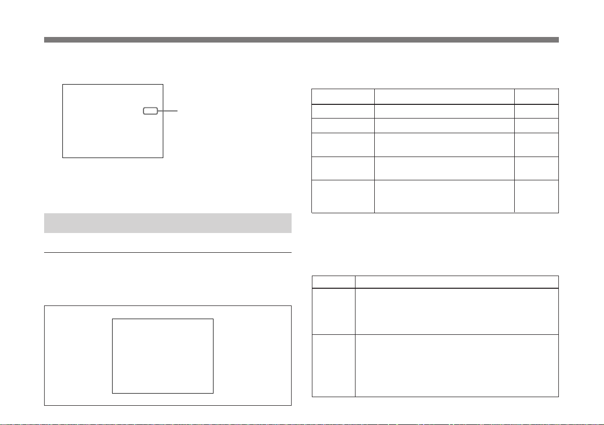
4 Changez la valeur en appuyant sur la touche DATA UP
ou DOWN.
PAGE 1 : NOR
SPEED
EXT. TR GGERI
I
DETECT ONI
scan
>
GA NI
SHUTTER
AE W NDOW
Pour revenir à l’écran normal du moniteur
Appuyez sur la touche MENU.
:A
STEP
0dB
STEP
1/125
ON
MED UM
I
PEAK
Valeur réglée
Le tableau suivant illustre les paramètres de la PAGE 1 du
menu, leur contenu et les pages de référence dans ce manuel.
Paramètre Contenu du réglage
GAIN Ajuste le gain vidéo. 77
SHUTTER
a)
Règle l’obturateur électronique. 78
EXT.TRIGGER Règle l’obturateur à enclenchement 80
externe sur ON ou OFF.
AE WINDOW Sélectionne la fenêtre AE en mode 80
AGC, CCD IRIS ou AUTO IRIS.
DETECTION Sélectionne la méthode de détection 80
du niveau de luminance de la fenêtre
AE sélectionnée.
Page de réf.
Fonctionnement des menus
PAGE 1 du menu
Cette section vous présente les détails des paramètres repris
à la PAGE 1 du menu.
>
PAGE 1 : NOR
GA NI
SHUTTER
EXT. TR GGERI
AE W NDOW
I
DETECT ONI
scan
:A
STEP
0dB
OFF
OFF
LARGE
AVERAGE
a)Lorsque “SHUTTER” est réglé sur STEP ou VARIABLE, “SPEED”
apparaît et vous pouvez régler la vitesse de l’obturateur.
GAIN
Ajuste le gain vidéo.
Sélection Fonction
AGC
Contrôle automatique du gain vidéo. Ajuste
automatiquement le gain du signal vidéo en fonction
de la luminosité du sujet. Cette fonction est utile lors
de la prise de vue d’objets dans des conditions
d’éclairage variables.
STEP
Règle le gain vidéo en mode de contrôle manuel.
Utilisez cette fonction pour des prises de vue dans des
endroits extrêmement sombres, lorsque l’ouverture
complète du diaphragme ne produit toujours pas une
image d’une clarté acceptable. Le réglage du niveau
de gain couvre une plage comprise entre 0 et 18 dB
par incréments de 1 dB.
77
Page 78

Ajustement et réglage à l’aide des menus
SHUTTER
L’obturateur électronique autorise des prises de vue
exemptes du flou lié au déplacement d’objets rapides et
produit des images fixes d’une clarté acceptable pour les
sujets faiblement éclairés.
Sélection Fonction
OFF
STEP
Désactive l’obturateur électronique.
Règle la vitesse de l’obturateur selon 9 possibilités en
mode d’obturateur haute vitesse et selon 15
possibilités en mode d’exposition longue.
Mode haute vitesse: 1/50, FL (sans scintillement),
1/125, 1/250, 1/500, 1/1000, 1/2000, 1/4000 et
1/10000 seconde
Mode d’exposition longue: 0,1, 0,2, 0,3, 0,5, 1,0, 1,5,
2,0, 2,5, 3,0, 3,5, 4,0, 5,0, 6,0, 7,0 et 8,0 sec.
Pour régler la vitesse d’obturation
1 Affichez 1/50 (réglage d’usine) en appuyant sur la
touche DATA UP et DATA DOWN simultanément.
2 Sélectionnez la vitesse d’obturation désirée en
appuyant sur la touche DATA UP ou DOWN.
Lorsque vous appuyez sur la touche UP: la
vitesse d’obturation change comme dans l’ordre
suivant, 1/50, FL (sans scintillement), 1/125,
1/250, 1/500, 1/1000, 1/2000, 1/4000 et 1/10000
chaque fois que vous appuyez sur la touche UP.
Lorsque vous appuyez sur la touche DOWN:
la vitesse d’obturation change dans l’ordre
suivant, 0,1, 0,2, 0,3, 0,5, 1,0, 1,5, 2,0, 2,5,
3,0, 3,5, 4,0, 5,0, 6,0, 7,0 et 8,0 sec.
Lorsque vous utilisez la caméra avec une puissance
d’éclairage de 60 Hz, le réglage de l’obturateur sur FL
autorise des images sans scintillement même sous un
éclairage fluorescent.
Sélection Fonction
VARIABLE
Utilisation pour le réglage fin du niveau de sortie
vidéo.
Vous pouvez ajuster la vitesse d’obturation en mode
d’exposition longue ou en mode Clear Scan.
En mode d’exposition longue. Vous pouvez régler
la vitesse d’obturation par unités de 1 cadre.
Par exemple, si la valeur est réglée sur 50 cadres
(environ 2,0 seconde dans le format PAL), la quantité
totale de signaux vidéo accumulés pendant ce temps
sort sous la forme d’un cadre complet par intervalles
d’environ 2,0 seconde. Ces images, qui contiennent
50 cadres d’informations vidéo, sont beaucoup plus
claires que les images normales à un cadre. Ce mode
de réglage de la vitesse d’obturation est très utile lors
de la prise de vue d’un sujet mal éclairé dans un
endroit sombre.
1 Affichez 312/625 (réglage d’usine) en appuyant sur
la touche DATA UP et DATA DOWN
simultanément.
2 Sélectionnez la vitesse d’obturation désirée en
appuyant sur la touche DATA DOWN.
Chaque fois que vous appuyez sur la touche DATA
DOWN, la vitesse d’obturation change par
incréments de 1 cadre à partir de 1 FRM jusqu’à
255 FRM.
Calcul de la vitesse d’obturation
Exemple: Vitesse d’obturation lorsque l’appareil est
réglé sur 5 cadres
5 x 1/25 = 0,20 seconde
Remarque
En mode d’exposition longue, AUTO IRIS ne peut
pas être utilisé.
78
Page 79

Sélection Fonction
VARIABLE
(Suite)
En mode Clear Scan
Vous pouvez régler la vitesse d’obturation par
incréments de 1 H (durée de balayage horizontal:
64 µs). Le réglage est effectué par unité de 1H. Ce
réglage peut s’utiliser pour réduire les parasites
(motifs horizontaux) lorsque vous filmez un écran
d’ordinateur.
1 Affichez 312/625 en appuyant sur la touche DATA
UP et DATA DOWN simultanément.
2 Sélectionnez le réglage de manière à réduire les
parasites en appuyant sur la touche DATA UP tout
en observant les parasites sur l’écran d’un
moniteur.
Chaque fois que vous appuyez sur la touche DATA
UP, la vitesse d’obturation change par incréments
de 1 H à partir de 312/625 jusqu’à 1/625.
Calcul de la vitesse d’obturation
Exemple: Vitesse d’obturation en 250/625 (H)
250 x 64 µs (1H) + 35,6 µs (constante) =
16035,6 µs = environ 0,016 seconde.
Sélection Fonction
CCD IRIS
Lorsqu’une quantité excessive de lumière traverse
l’objectif, cette fonction augmente la vitesse
d’obturation pour réduire l’exposition jusqu’à un
maximum de 4 arrêts d’ouverture du diaphragme.
Cette fonction est utile pour les applications au
microscope lorsque l’éclairage, qui est juste suffisant
pour l’oeil humain, est généralement trop lumineux
pour la caméra vidéo.
Lorsque CCD-IRIS est réglé sur ON, la lumière
incidente excessive est automatiquement ramenée à
un niveau approprié pour la caméra vidéo. La fonction
de contrôle de diaphragme CCD est également très
utile pour réduire l’excès de lumière incidente qui n’est
pas atténuée par l’objectif à diaphragme automatique
dans les scènes contenant des portions très
lumineuses (tels que la neige ou l’eau de mer reflétant
le soleil).
Vous pouvez utiliser CCD IRIS en combinaison avec
AGC et/ou AUTO IRIS.
79
Page 80

Ajustement et réglage à l’aide des menus
EXT.TRIGGER
Active et désactive l’enclenchement externe de l’obturateur.
Sélection Fonction
ON Active l’enclenchement externe de l’obturateur.
OFF Désactive l’enclenchement externe de l’obturateur.
Mettez en principe cette option sur OFF.
AE WINDOW
Sélectionne l’exposition automatique AE lorsque la caméra
est utilisée avec le réglage suivant.
• AGC (contrôle automatique du gain vidéo)
• CCD IRIS de SHUTTER
• Utilisation de l’objectif à diaphragme automatique
Lorsque vous filmez un sujet très petit, le point que vous
désirez voir s’éclaircit si vous réglez “AE WINDOW” sur
“SPOT”.
Lorsque vous mettez le curseur sur AE WINDOW, la
fenêtre AE actuellement sélectionnée apparaît sur le
moniteur. Chaque fois que vous appuyez sur la touche
DATA UP ou DATA DOWN, la fenêtre AE change.
Fenêtres AE
LARGE (Grand) Medium (Moyen) Spot (Point)
DETECTION
Sélectionne la méthode de détection du niveau de luminance
de la fenêtre AE sélectionnée.
Sélection Fonction
AVERAGE Permet de voir toute la fenêtre AE.
PEAK Permet de voir la partie avec le plus haut niveau
vidéo dans la fenêtre AE.
80
Page 81

PAGE 2 du menu
Cette section vous présente en détail les paramètres de la
PAGE 2 du menu.
>
PAGE 2 : NOR
C. TEMP
W
HT. BAL
M. PEDESTAL
GAMMA
DETA L
a nti
R P
a nti
B P
I
LEVEL
scan
Le tableau suivant illustre les paramètres de la PAGE 2 du
menu, leur contenu et les pages de référence dans ce manuel.
Paramètre Contenu du réglage
C.TEMP Sélectionne la température des couleurs 81
WHIT.BAL Sélectionne les réglages de la balance 81
M.PEDESTAL Règle le niveau de base du signal de 82
GAMMA Procède à une compensation Gamma 82
DETAIL Permet d’activer la fonction DETAIL 82
a)
LEVEL
en fonction des conditions d’éclairage.
du blanc.
sortie.
(activée/désactivée).
(activée/désactivée).
Ajuste la netteté du contour de l’objet. 83
:A
AUTO
AWB
±
00
±
00
±
00
ON
ON
±
00
Page de réf.
C TEMP.
Sélectionne la température de la couleur en fonction de
l’éclairage.
Sélection Conditions d’éclairage
AUTO
Utilisation pour un ajustement automatique de la
température de la couleur avec “WHIT.BAL” réglé
sur “AWB”.
3200K
5600K
Utilisation pour une prise de vue en intérieur.
Utilisation pour une prise de vue en extérieur.
WHIT.BAL
Sélectionne les réglages de la balance du blanc.
Sélection Fonction
AWB
MANU Utilisation pour le réglage manuel de la balance du
Utilisation pour l’ajustement automatique de la
balance du blanc.
Pour plus de détails, reportez-vous à “Réglage de la
balance du blanc”.
Pour plus de détails sur le réglage fin à l’aide de “R Paint”
et de “B Paint”, reportez-vous à ATW ci-après.
blanc. Le gain rouge (R Gain) et le gain bleu (B Gain)
sont tous deux réglables.
R Gain: Ajuste le gain rouge (–127 à +127)
B Gain: Ajuste le gain bleu (–127 à +127)
En appuyant sur les touches DATA UP et DATA
DOWN simultanément, les valeurs sont remises sur
±000.
(suite)
a) Ce paramètre apparaît lorsque DETAIL est réglé sur ON.
81
Page 82

Ajustement et réglage à l’aide des menus
Sélection Fonction
ATW
Active la balance d’auto-traçage du blanc. Ce mode
convient particulièrement aux situations présentant
des sources de lumière changeantes. La balance du
blanc est réglée automatiquement en fonction du
changement de la température de la couleur.
Lorsque WHIT.BAL est réglé sur AWB ou ATW, les
valeurs “R Paint” et “B Paint” s’affichent sur le menu.
Utilisez-les pour le réglage fin. Ajustez-les en
observant les valeurs à l’écran.
R Paint: Ajuste la peinture rouge (–10 à +10)
B Paint: Ajuste la peinture bleue (–10 à +10)
En appuyant sur les touches DATA UP et DATA
DOWN simultanément, ces valeurs sont remises à
±00.
Niveau de base maître (M. PEDESTAL)
Normalement, cette fonction est réglée sur +00.
Règle le niveau de noir des parties sombres de l’écran.
Utilisez cette fonction pour faire ressortir les détails de
zones fortement assombries. Un moniteur de forme d’onde
vous facilitera le réglage.
Les niveaux de base maître des signaux de sortie R, G, B
peuvent être ajustés simultanément dans une plage comprise
entre –99 et +99.
Réglage de la direction Contour de l’image
+ Plus clair
– Plus foncé
Correction GAMMA
Procède à une compensation Gamma.
Sélection Fonction
ON
OFF
Compense les caractéristiques de reproduction
d’image de l’écran pour produire des images à teintes
naturelles.
Sortie linéaire du signal vidéo à partir du CCD sans
aucune compensation Gamma. Utilisez ce réglage
lorsque vous désirez produire des images pour un
traitement ou une analyse d’images.
DETAIL
Permet de sélectionner le réglage de la netteté des contours
des sujets de l’image.
Sélection Fonction
ON Permet de régler la netteté des contours des sujets de
OFF Ne permet pas de régler la netteté des contours des
l’image.
sujets de l’image.
En appuyant sur les touches DATA UP et DATA DOWN
simultanément, les valeurs sont remises à ±00.
82
Page 83

LEVEL
Ce paramètre apparaît lorsque “DETAIL” est réglé sur
“ON”.
Règle la netteté des contours des sujets dans une plage
comprise entre -99 et +99 lorsque DETAIL est réglé sur ON.
Réglage de direction Contour de l’image
+ Contour de l’image plus net et plus détaillé.
– Image plus douce avec moins de détails.
En appuyant sur les touches DATA UP et DATA DOWN
simultanément, les valeurs sont remises à ±00.
PAGE 3 du menu
Cette section présente en détails les paramètres de la PAGE
3 du menu.
>
PAGE 3 : NOR
H. PHASE
SC PHASE R
G SYNC
D–SUB V
D–SUB S
EXT. CTRL (BNC)
FREEZE
ideo
ync
scan
F
ough
ine
±
±
Y / C
C. SYNC
TR G. N
II
I
NT. CTRL
00
00
ON
:A
0
Les tableaux suivants illustrent les paramètres de la PAGE 3
du menu, leur contenu et les pages de référence dans ce
manuel.
Paramètre Contenu des réglages Page de
H.PHASE
SC PHASE
Ajuste la différence de phase entre
la synchronisation de sousporteuse et horizontale au cours de
la synchronisation externe.
G SYNC
Ajoute un signal de synchro au
canal G (vert) de la sortie RGB.
D-SUB Video
Sélectionne le signal vidéo de
sortie du connecteur RGB/
SYNC (D-sub).
D-SUB Sync
Sélectionne le signal de synchro de
sortie du connecteur RGB/
SYNC (D-sub).
EXT.CTRL (BNC)
Sélectionne le signal d’entrée du
signal EXT CTRL (signal de
synchro/signal d’impulsion externe)
FREEZE
Sélectionne le mode de capture de
l’image dans la mémoire (signal
d’impulsion externe/touche
FREEZE sur le panneau
arrière).
MODE
a)
Sélectionne le mode de mémoire
(F/F ou F/S)
a) Ce paramètre apparaît lorsque FREEZE est réglé sur
“EXT.CTRL”.
référence
84
84
84
85
85
85
85
83
Page 84

Ajustement et réglage à l’aide des menus
H.PHASE
Quand un signal de synchro de référence externe est entré au
connecteur EXT CTRL à l’arrière de l’appareil pour
verrouiller la caméra, la caméra fonctionne à la fréquence de
ce signal de référence. La fonction H.PHASE peut servir à
synchroniser parfaitement l’exploitation de la caméra avec
signal de référence au niveau de la phase horizontale.
Vous pouvez ajuster le niveau dans une plage comprise
entre –99 et +99.
En appuyant sur les touches DATA UP et DATA DOWN
simultanément, les valeurs sont remises à ±00.
Remarques
• Pour effectuer ce réglage, mettez “EXT.CTRL (BNC)” sur
“GENLOCK”. Si vous mettez “EXT.CTRL (BNC)” sur
“TRIG.IN”, aucune valeur ne s’affiche.
• Lorsqu’un signal de référence externe n’est pas entré via le
connecteur EXT CTRC, vous ne pouvez pas modifier la
valeur réglée.
SC PHASE
Quand la caméra est verrouillée à un générateur, utilisez la
fonction SC PHASE pour régler la phase de la sousporteuse.
Sélection Fonction
SC PHASE Réglage grossier entre 0° et 180°.
SC PHASE Fine Réglage fin entre –99 et +99.
En appuyant sur les touches DATA UP et DATA DOWN
simultanément, les valeurs sont remises à ±00.
84
Remarques
• Pour effectuer ce réglage, mettez “EXT.CTRL (BNC)” sur
“GENLOCK”. Si vous mettez “EXT.CTRL (BNC)” sur
“TRIG.IN”, aucune valeur n’apparaîtra.
• Lorsqu’un signal de référence externe n’est pas entré via le
connecteur EXT CTRC, vous ne pouvez pas modifier la
valeur réglée.
G Sync (G avec synchro)
Ajoute un signal de synchro au signal G à la sortie RGB.
Sélection Fonction
ON
OFF
Poru utiliser un moniteur vidéo sans connecteur
d’entrée synchro. Le signal G plus synchro peut être
fourni par le connecteur RGB/SYNC de la
caméra (panneau arrière).
Aucun signal de synchro n’est ajouté au signal G de
sortie.
D-SUB Video
Sélectionne le signal de sortie du connecteur RGB/
SYNC (D-sub 9 broches).
Selection Signal de sortie
VBS Signal VBS
YC Signal YC
VD Signal VD. Le signal VD est automatiquement
sélectionné lorsque “D-SUB Sync” est mis sur “HD”.
Page 85

D-SUB Sync
Sélectionne le signal de synchro de sortie du connecteur
RGB/SYNC (D-sub 9 broches).
FREEZE
Sélectionne le signal de commande pour permettre à la
mémoire intégrée de capturer l’image.
Sélection Signal de synchro de sortie
C.SYNC
WEN Signal WEN. Un signal WEN sort vers l’appareil
HD
Signal SYNC composite
périphérique sous forme d’impulsion d’enclenchement
Remarque
Raccordez la caméra à l’appareil périphérique après
avoir terminé tous les réglages menu.
Signal HD. Lorsque HD est sélectionné, “D-SUB
Video” est automatiquement réglé sur “VD”.
EXT. CTRL (BNC)
Sélectionne le signal d’entrée vers le connecteur EXT CTRL
situé sur le panneau arrière.
Sélection Signal d’entrée
TRIG.IN
GENLOCK
Signal de commande pour la mémoire intégrée et
l’obturateur à enclenchement externe.
Signal de synchro permettant de synchroniser le
fonctionnement de la caméra au signal de référence.
Sélection Signal de commande
INT.CTRL
EXT.CTRL
Pour que la touche FREEZE située sur le
panneau arrière soit en mesure de capturer l’image
dans la mémoire intégrée.
Le signal d’impulsion externe sert à capturer l’image
dans la mémoire intégrée.
MODE
Ce paramètre apparaît lorsque “FREEZE” est mis sur
“EXT.CTRL”.
Sélectionne le mode de commande de la caméra à l’aide de
l’impulsion externe.
Sélection Méthode de commande
F/F
F/S Lorsque l’impulsion externe entre, l’image est
Lorsqu’une impulsion externe est entrée, l’image est
capturée dans la mémoire, remplaçant l’image
précédemment capturée par une nouvelle.
capturée dans la mémoire, remplaçant ainsi l’image
précédemment capturée par la nouvelle et l’image
capturée sort comme image fixe. Lorsque le signal
d’impulsion externe suivant entre, l’image animée
filmée avec la caméra sort. Ces opérations sont
répétées cycliquement chaque fois que les impulsions
externes entrent.
85
Page 86

Ajustement et réglage à l’aide des menus
PAGE 4 du menu
Cette section décrit en détails les paramètres de la PAGE 4
du menu.
>
PAGE 4 : NOR
USER PRESET
BAUD RATE
TR GGER PULSE
R S MODE
II
AE LEVEL
MENU SW
scan
PROTECT
I
OFF
9600
AUTO
±
OFFTR GGER CYCLEI
OFF
:A
A
00
86
Les tableaux suivants illustrent les paramètres de la PAGE 4 du
menu, leur contenu et les pages de référence dans ce manuel.
Paramètre Contenu des réglages
Page de réf.
USER PRESET Sélectionne la présélection 86
utilisateur A ou B.
PROTECT Protège la présélection utilisateur. 87
BAUD RATE Sélectionne le débit en bauds. 87
TRIGGER PULSE Sélectionne la polarité de 87
l’impulsion d’entrée.
IRIS MODE Sélectionne le mode du diaphragme 87
(auto/fixe)
AE LEVEL
a)
Règle finement le point de mise au 87
point de la fenêtre AE
TRIGGER CYCLE Sélectionne le cycle de l’impulsion 88
d’enclenchement interne.
MENU SW Sélectionne le mode de 88
changement de la présélection
utilisateur (sur le menu/à l’aide de
la touche FUNCTION UP).
a) Ce paramètre apparaît lorsque IRIS MODE est réglé sur AUTO.
USER PRESET
Vous pouvez conserver un maximum de deux présélections
utilisateur pour les spécifications de la caméra, réglées ou
ajustées à l’aide des menus, et enregistrer les réglages
comme présélection utilisateur. Vous pouvez rappeler le
réglage utilisateur le plus adéquat pour les conditions de
prise de vue présentes. Le réglage utilisateur sélectionné est
affiché dans le coin supérieur gauche du menu.
Page 87

PROTECT
Vous pouvez protéger chaque présélection utilisateur en
mettant “PROTECT” sur “ON.”
Pour enregistrer les réglages utilisateur et les protéger
1 Sélectionnez la présélection utilisateur A ou B que vous
désirez enregistrer dans “USER PRESET”.
2 Effectuez les réglages et les ajustements de la PAGE 1
du menu à la PAGE 4 du menu.
3 Mettez “PROTECT” sur “ON.”
Le “P” clignotant apparaît en regard de la présélection
utilisateur A ou B affichée. Il s’agit du signe indiquant
que la présélection utilisateur est protégée.
Sachez que le paramètre suivant peut être modifié même
lorsque la présélection utilisateur est protégée.
• USER PRESET
• PROTECT
BAUD RATE
Change le débit en bauds du connecteur REMOTE à 9600,
4800, 2400 ou 1200.
Utilisez un débit en bauds de 9600 lorsqu’une unité de
télécommande RM-C950 est raccordée.
TRIGGER PULSE
Sélectionne la polarité d’enclenchement qui correspond à la
polarité du signal d’entrée permettant de contrôler la
mémoire ou l’obturateur à enclenchement externe.
Sélection Polarité
Inférieur
Supérieur
IRIS MODE
Règle le mode du diaphragme.
Sélection Fonction
AUTO Pour utiliser l’objectif à diaphragme automatique.
FIX Pour utiliser l’objectif optique sans fonction de
diaphragme automatique.
AE LEVEL
Ce paramètre apparaît lorsque IRIS MODE est réglé sur
AUTO.
Le niveau du point de mise au point de l’exposition
automatique peut être ajusté dans une plage comprise entre
–31 et +31 en appuyant sur la touche DATA UP ou DATA
DOWN.
En appuyant sur les touches DATA UP et DATA DOWN
simultanément, les valeurs sont remises à ±00.
87
Page 88

Ajustement et réglage à l’aide des menus
TRIGGER CYCLE
Règle le cycle lorsque la mémoire intégrée est commandée
par l’impulsion interne.
Sélection Fonction
OFF La mémoire intégrée est commandée par
2-FRM à 10 min Règle le cycle de l’impulsion interne dans la
l’impulsion externe.
plage comprise entre 2-FRM et 10 min.
MENU SW
Permet de choisir la présélection utilisateur A ou B grâce à
la touche FUNCTION UP du panneau arrière sans afficher
le menu.
Sélection Fonction
OFF Commute la présélection utilisateur sur le menu.
ON
Rend la touche FUNCTION UP opérationnelle pour
commuter la présélection utilisateur.
Chaque fois que vous appuyez sur la touche
FUNCTION UP, la présélection utilisateur commute
instantanément.
Par exemple, si la présélection utilisateur A est sélectionnée
lorsque “MENU SW” est réglé sur ON, la présélection
utilisateur commute sur B lorsque la touche FUNCTION UP
est enfoncée après être revenu à l’écran normal.
Remarque
Lorsque vous commutez la présélection utilisateur à l’aide
de la touche FUNCTION UP, le nom de la présélection
utilisateur actuellement sélectionnée n’est pas affichée sur le
moniteur.
88
Page 89
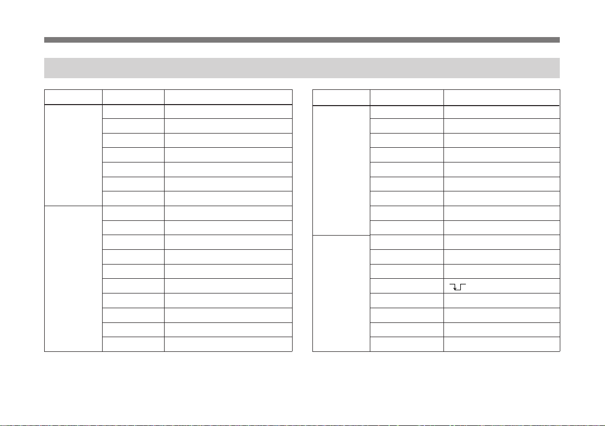
Liste de réglage initial
MENU PAGE Paramètre Réglage initial
PAGE 1
GAIN STEP:0 dB
SHUTTER OFF
a)
SPEED
STEP:1/50
VARIABLE:312/625
EXT.TRIGGER OFF
AE WINDOW LARGE
DETECTION AVERAGE
PAGE 2
C.TEMP AUTO
WHT.BAL AWB
R Paint:±00
B Paint:±00
R Gain:±000
B Gain:±000
M.PEDESTAL ±00
GAMMA ON
DETAIL ON
b)
LEVEL
±00
a) “SPEED” apparaît lorsque “SHUTTER” est mis sur “STEP” ou
“VARIABLE”.
b) “LEVEL” apparaît lorsque “DETAIL” est réglé sur “ON”.
MENU PAGE Paramètre Réglage initial
PAGE 3
H.PHASE ±00
SC PHASE Rough 0
SC PHASE Fine ±00
G SYNC ON
D-SUB Video Y/C
D-SUB Sync C.SYNC
EXT.CTRL(BNC) TRIG.IN
FREEZE INT.CTRL
c)
PAGE 4
MODE
USER PRESET A
F/S
PROTECT OFF
BAUD RATE 9600
TRIGGER PULSE
IRIS MODE AUTO
AE LEVEL
d)
±00
TRIGGER CYCLE OFF
MENU SW OFF
c) “MODE“ apparaît lorsque “FREEZE” est réglé sur “EXT. CTRL”.
d) “AE LEVEL” apparaît lorsque “IRIS MODE” est réglé sur “AUTO”.
89
Page 90

Prise de vue
Procédure fondamentale
1 Mettez la caméra et tous les appareils connectés sous
tension.
2 Eclairez correctement le sujet.
90
2
3 Orientez la caméra dans la bonne direction, réglez le
diaphragme, effectuez la mise au point et zoomez sur le
sujet.
4 Réglez la balance du blanc.
Pour plus de détails, reportez-vous à “Réglage de la balance
du blanc” à la page 91.
3
4, 5
5 Effectuez les réglages nécessaires.
Pour plus de détails, reportez-vous à “Ajustement et réglage à
l’aide des menus” à la page 73.
6 Commencez la prise de vue.
Page 91

Réglage de la balance du blanc
>
:A
±
00
±
00
ON
OFF
PAGE 2 : NOR
M. PEDESTAL
GAMMA
DETA L
scan
AUTO
AWB
C. TEMP
W
HT. BAL
I
R P
B P
a nti
a nti
±
00
La balance du blanc de la caméra doit être réglée à chaque
modification des conditions d’éclairage afin d’assurer la
reproduction optimale des couleurs.
2
UP
DOWN
SCAN
REMOTE
7
LENS
WHITE
EXT CTRL
1, 3
FREEZE
SOURCE
VIDEO OUT
MENU FUNCTION DATA
BARS
RGB/SYNC
DC IN/
VBS
Réglage de la balance du blanc
1 Appuyez sur la touche MENU pour afficher le menu.
2 Sélectionnez la PAGE 2 du menu et réglez
“WHT.BAL” sur “AWB”.
Remarque
Assurez-vous que “PROTECT” à la PAGE 4 du menu
est réglé sur “OFF”. S’il est réglé sur “ON”, vous ne
pouvez pas mettre “WHT.BAL” sur “AWB”.
Pour plus de détails, reportez-vous à “PROTECT” de la
“PAGE 4 du menu” à la page 87.
Pour plus de détails sur la méthode de fonctionnement,
reportez-vous à “Utilisation des menus” à la page 75.
3 Appuyez sur la touche MENU pour faire disparaître le
menu.
(Suite)
91
Page 92

Prise de vue
4 Affichez l’image de la caméra à l’écran.
Remarque
Si le signal de barre couleur est affiché sur l’écran,
appuyez sur la touche BAR pour le faire disparaître.
5 Réglez la commande du diaphragme comme suit:
Si vous utilisez un objectif avec fonction de
diaphragme automatique: réglez-la sur la commande à
diaphragme automatique.
Si vous utilisez un objectif à diaphragme manuel:
Réglez-la sur la valeur d’ouverture de diaphragme
appropriée.
6 Placez un objet blanc dans la même lumière que celle
éclairant le sujet à filmer, orientez la caméra vers cet
objet et réglez le zoom.
20% de la hauteur de l’écran
L’objet blanc doit
15% de la
largeur de
l’écran
15% de
la largeur
de l’écran
10% de la hauteur de l’écran
être placé dans ce
rectangle. (Evitez
tout rehaut très
clair dans le
rectangle.)
Remarques
• N’incluez pas d’objets fortement réfléchissants dans
l’image.
• Réalisez toujours vos prises de vue dans des conditions
d’éclairage favorables.
7 Appuyez sur la touche ∑ WHITE.
Le message “WHITE OK” apparaît à l’écran lorsque le
réglage est effectué.
Le niveau de blanc réglé est automatiquement conservé
en mémoire et y reste même lorsque l’alimentation de la
caméra est coupée.
Pour filmer dans les mêmes conditions, la balance du
blanc enregistrée est reproduite lorsque “WHIT.BAL”
est mis sur “AWB”.
Erreurs de réglage de la balance du blanc
Si le réglage de la balance du blanc ne se fait pas
correctement, un message d’erreur apparaît à l’écran. Si
c’est le cas, prenez les mesures nécessaires et répétez les
étapes 1 à 7.
Pour plus de détails, reportez-vous à “Messages d’erreur” à la
page 93.
L’objet blanc peut être un morceau de papier ou de tissu
blanc, un mur blanc ou quelque chose de similaire.
92
WH TE NGI
LLEVE LOW
Message d’erreur
Page 93

Messages d’erreur
Le tableau suivant reprend les messages d’erreur qui
traduisent le problème lorsque vous effectuez le réglage
automatique de la balance du blanc, ainsi que les causes
possibles et les remèdes.
Retenez le message et agissez en conséquence.
Message d’erreur
WHITE NG
LEVEL LOW
WHITE NG
LEVEL HIGH
WHITE NG
C.TEMP LOW
WHITE NG
C.TEMP HIGH
Causes Remèdes
Le niveau vidéo
est trop bas.
Le niveau vidéo
est trop élevé.
La température
de la couleur est
trop basse.
La température de
la couleur est trop
élevée.
Augmentez l’éclairage.
Réduisez l’éclairage.
La caméra ne parvient pas
à effectuer le réglage
automatique de la balance
du blanc en raison de
l’éclairage. Réglez
l’éclairage de manière
appropriée.
La caméra ne parvient pas
à effectuer le réglage
automatique de la balance
du blanc en raison de
l’éclairage. Réglez
l’éclairage de manière
appropriée.
Message d’erreur
WHITE NG
TRY AGAIN
WHITE MANU “WHT.BAL” est
WHITE ATW “WHT.BAL” est
Causes Remèdes
La caméra n’est
pas parvenue à
régler la balance
du blanc pour une
raison autre que
celles indiquées
ci-dessus. (ex. il
n’y a aucune
partie blanche sur
l’objet, l’objet se
déplace, etc.)
réglé sur
“MANU”.
réglé sur “ATW”.
Préparez l’objet adéquat et
réessayez le réglage
automatique de la balance
du blanc.
Mettez le réglage de
“WHT.BAL” sur “AWB”,
puis réessayez le réglage
automatique de la balance
du blanc.
Mettez le réglage de
“WHT.BAL” sur “AWB”,
puis réessayez le réglage
automatique de la balance
du blanc.
93
Page 94

Prise de vue
Utilisation de l’obturateur à enclenchement externe
Une charge commence à s’accumuler dès qu’un signal
d’enclenchement externe entre et puis une image sort.
L’enclenchement externe de l’obturateur électronique vous
permet de filmer un objet se déplaçant à grande vitesse à
partir d’un emplacement fixe avec un minimum de flou.
Pour utiliser l’obturateur à enclenchement externe, effectuez
les réglages du menu suivants.
Pour plus de détails sur la façon d’utiliser le menu, reportez-vous
à “Utilisation des menus” à la page 75.
1 Mettez “EXT.TRIGGER” de “SHUTTER” à la PAGE 1
du menu sur “ON”.
Soit STEP, soit VARIABLE apparaît dans la colonne
SHUTTER du menu.
2 Sélectionnez soit “STEP”, soit “VARIABLE”.
“SPEED” apparaît.
3 Déplacez le curseur sur “SPEED” en utilisant la touche
FUNCTION DOWN, puis réglez la vitesse d’obturation
à l’aide des touches DATA UP ou DOWN.
4 Mettez “EXT.CTRL(BNC)” de la PAGE 3 du menu sur
“TRIG.IN”.
5 Mettez “TRIGGER CYCLE” de la PAGE 4 du menu
sur “OFF”.
6 Réglez “TRIGGER PULSE” de la PAGE 4 du menu sur
la même polarité que la polarité de l’impulsion
d’enclenchement d’entrée.
Remarque
Lorsque “EXT.TRIGGER” est réglé sur “ON”, ATW et
AUTO IRIS ne peuvent pas être utilisés.
94
Page 95

Capture de l’image dans la mémoire à l’aide de la fonction d’image fixe (Freeze)
Etant donné que cette caméra est équipée de la mémoire de
cadre permettant de capturer l’image, l’image capturée sort
sous forme d’image fixe vers le processeur d’image, comme
un ordinateur et une imprimante.
Il existe trois possibilités de commander la mémoire.
• La touche FREEZE située sur le panneau arrière
• Le signal d’impulsion interne
• Le signal d’impulsion externe
Vous devez effectuer un réglage du menu pour utiliser la
fonction d’image fixe à l’aide des commandes décrites cidessus.
Remarque
Lorsque l’image capturée sort comme image fixe, ATW,
AUTO IRIS et CCD IRIS ne peuvent pas être utilisés.
Pour capturer l’image en mémoire à l’aide de la
touche FREEZE
Réglez “FREEZE” de la PAGE 3 du menu sur “INT.CTRL”.
La touche FREEZE et la touche SOURCE sur le panneau
arrière deviennent opérationnelles.
Lorsque vous appuyez sur la touche FREEZE: l’image
est capturée en mémoire et l’image capturée sort.
Lorsque vous appuyez sur la touche SOURCE: la
fonction d’image fixe (mode mémoire) est annulée et
l’image animée sort de la caméra.
Pour capturer l’image en mémoire à l’aide du
signal d’impulsion interne
Pour capturer l’image en mémoire à l’aide du signal
d’impulsion interne, effectuez les réglages du menu
suivants.
1 Réglez “FREEZE” de la PAGE 3 du menu sur
“EXT.CTRL”.
2 Réglez “MODE” de la PAGE 3 du menu sur le mode de
mémoire désiré F/F ou F/S.
F/F: Chaque fois que l’impulsion externe est entrée,
l’image est capturée dans la mémoire, remplaçant
l’image capturée précédemment par la nouvelle et
l’image capturée sort comme image fixe. Cette
opération est répétée cycliquement chaque fois que
des impulsions externes sont entrées.
F/S:Lorsque l’impulsion externe est entrée, l’image est
capturée dans la mémoire en remplacement de
l’image précédemment capturée et l’image
capturée sort comme image fixe. Lorsque le signal
d’impulsion externe entre, l’image animée filmée par
la caméra sort. Ces opérations sont répétées
cycliquement chaque fois que les impulsions
externes entrent.
Pour la synchronisation du signal d’impulsion en mode F/F et
en mode F/S, reportez-vous à “Synchronisation de l’impulsion
externe entrée au connecteur EXT CTRL” à la page 96.
(Suite)
95
Page 96

Prise de vue
3 Réglez le cycle pour capturer l’image dans une plage
comprise entre 2-FRM et 10 min à l’aide de “TRIGGER
CYCLE” de la PAGE 3 du menu.
L’image est capturée en mémoire à des cycles réglés à
l’étape 3.
Remarque
Lorsque le cycle de capture de l’image dans une plage
comprise entre 2-FRM et 10 min est réglé à l’aide de
“TRIGGER CYCLE” de la PAGE 3 du menu, CCD IRIS et
AUTO IRIS ne peuvent pas être utilisés.
Pour capturer l’image en mémoire à l’aide du
signal d’impulsion externe
Pour capturer l’image en mémoire en fonction du signal
d’impulsion externe entré via le connecteur EXT CTRL sur
le panneau arrière, effectuez les réglages du menu suivants.
1 Réglez “FREEZE” de la PAGE 3 du menu sur
“EXT.CTRL”.
2 Réglez “MODE” de la PAGE 3 du menu sur le mode
désiré F/F ou F/S.
Pour plus de détails sur le mode mémoire, reportez-vous à
l’étape 2 de “Pour capturer l’image en mémoire à l’aide du
signal d’impulsion interne” à la page 95.
3 Réglez “EXT.CTRL(BNC)” de la PAGE 3 du menu sur
“TRIG.IN”.
4 Réglez “TRIGGER CYCLE” de la PAGE 4 du menu
sur “OFF”.
5 Réglez “TRIGGER PULSE” de la PAGE 4 du menu sur
la même polarité que la polarité de l’impulsion
d’enclenchement d’entrée.
6 Réglez “EXT.TRIGGER” de “SHUTTER” de la PAGE
1 du menu sur “OFF”.
Synchronisation de l’impulsion externe entrée au
connecteur EXT CTRL
Mode F/F
Mémoire
Sélectionne l’un des deux illustré ci-dessus.
Mode F/S
Source
Mémoire: Capture de l’image dans la mémoire et diffusion
comme image fixe
Source: Remplacement de la sortie d’image capturée en
image animée.
Bas niveau de 0 à 0,5 V
Haut niveau de 4,5 à 5,0 V
Largeur d’impulsion
de 10µs à 10 mS
Mémoire
Source Source
Cycle d’enclenchement
de 3 V ou plus
MémoireMémoireMémoireMémoire
Mémoire
96
Page 97
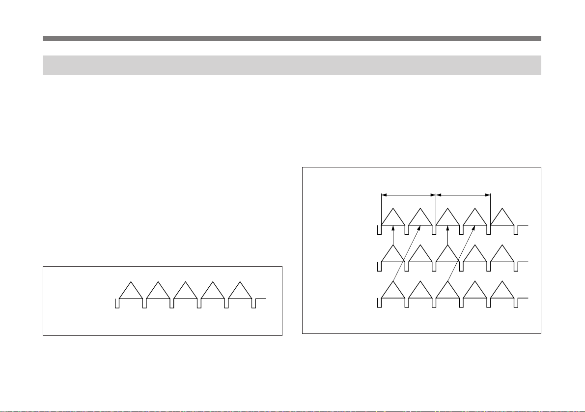
Réglage du mode de balayage (Scan)
Etant donné que le DXC-9100P est équipé d’un capteur
CCD qui utilise la méthode “affichage de tous les pixels”, la
caméra est munie d’une fonction d’obturation à cadre. Cette
fonction permet de sortir une image fixe à cadre intégral à
l’aide de l’obturateur électronique uniquement.
La caméra offre les trois modes de balayage suivants.
• NOR (mode normal)
• F.S (mode d’obturateur à cadre)
• Mode N.I.
Chaque mode est décrit ci-dessous à l’aide des
chronogrammes.
Mode NOR (normal)
Ce mode convient lorsque vous utilisez la sortie caméra
uniquement à des fins de contrôle, là où la fonction
d’obturateur à cadre n’est pas nécessaire.
Sortie CCD 1
(Sortie du
signal vidéo)
OEOEO
O: impair
P: pair
Un canal des sorties CCD est utilisé.
Le signal vidéo sort de la caméra sans passer via la
mémoire. Le signal à trame impaire sortent alternativement.
Mode F.S (obturateur à cadre)
Les signaux vidéo de 25 cadres sont émis pendant une
seconde.
Ce mode convient lorsque vous filmez un objet se déplaçant
à vitesse élevée à partir d’un emplacement fixe avec un
minimum de flou à l’aide de la fonction d’obturateur à
cadre.
1 cadre
(1/25 sec.)
Sortie mémoire
(sortie du signal
vidéo)
Sortie CCD 1
Sortie CCD 2
OEOEO
OEOEO
EOEOE
O: impair
E: pair
Le signal de trame impaire et le signal de trame paire sont
envoyés en même temps vers la mémoire et ils y sont
entrelacés pour ressortir sous la forme d’un signal vidéo à
un cadre.
97
Page 98

>
:A
OFF
OFF
MED UM
PEAK
PAGE 1 : NOR
SHUTTER
AE W NDOW
scan
AGC
GA NI
EXT. TR GGERI
I
DETECT ONI
I
Prise de vue
Mode N.I. (Sorties RGB)
Ce mode possède la même fonction d’obturateur à cadre.
Ce mode convient lors du raccordement à un moniteur
multi-balayage ou à une imprimante multi-balayage.
Sortie mémoire
(sortie du signal
vidéo)
Sortie CCD 1
Sortie CCD 2
Le signal de trame impaire et le signal de trame paire sont
envoyés en même temps vers la mémoire et ils y sont traités
comme signaux vidéo à un cadre pendant la durée d’une
trame. Les signaux vidéo de 50 cadres sont envoyés en une
seconde. Par conséquent, la caméra peut émettre deux fois
plus de signaux vidéo que la méthode conventionnelle.
98
1 cadre
(1/50 sec.)
O+E O+E O+E O+E O+E
OEOEO
EOEOE
O: pair
E: impair
Pour sélectionner le mode de balayage
1 Appuyez sur la touche MENU.
Le menu apparaît et le mode de balayage actuellement
sélectionné s’affiche.
Vérifiez le mode de balayage actuellement sélectionné.
Mode de balayage
actuellement
sélectionné
2 Appuyez sur la touche MENU.
L’écran normal du moniteur apparaît.
3 Sélectionnez le mode de balayage désiré en appuyant
sur la touche SCAN située sur le panneau arrière.
Le mode de balayage change dans l’ordre suivant:
NOR, F.S et N.I., chaque fois que vous appuyez sur la
touche SCAN.
Remarque
Vous ne pouvez pas commuter le mode de balayage lorsque
le menu est affiché sur le moniteur.
Page 99

Réglage de la teinte d’image dans un système multi-caméra
En système multi-caméra, il convient de régler toutes les
caméras pour éviter les variations de teinte d’image d’une
caméra à l’autre.
Avant d’effectuer les réglages décrits ci-dessous, fournissez
le même signal de synchro à toutes les caméras.
Pour plus de détails, reportez-vous à “Connexions pour un système
multi-caméra” à la page 107.
Raccordement des caméras à un appareil
vidéo à indication de phase
Quand les caméras sont raccordées à un générateur d’effets
spéciaux, à un incrustateur couleur ou à un autre appareil à
indication de phase, la procédure de réglage de base est la
suivante.
1 Activez la fonction d’indication de phase de l’appareil
vidéo raccordé.
2 Réglez la phase horizontale avec la fonction
“H.PHASE” de la PAGE 3 du menu.
Pour plus de détails, reportez-vous à “Utilisation des menus”
à la page 75.
3 Réglez la phase de la sous-porteuse à l’aide de la
fonction “SC PHASE” de la PAGE 3 du menu.
Effectuez d’abord un réglage grossier entre 0° et 180° à
l’aide de “SC PHASE Rough”, puis procédez à un
réglage fin à l’aide de “SC PHASE Fine”.
Pour plus de détails, consultez le mode d’emploi de l’appareil
vidéo à indication de phase raccordé.
Raccordement de caméras à un appareil vidéo
sans indication de phase
Utilisez l’une des caméras comme caméra de référence et
réglez les autres une à une par rapport à elle.
1 Réglez la phase horizontale à l’aide de la fonction “H.
PHASE” de la PAGE 3 du menu.
A l’aide de la fonction “H. PHASE”, effectuez le
réglage de sorte que le signal vidéo de référence et le
signal de sortie aient la même phase de synchro
horizontale. Utilisez un moniteur de forme d’onde ou un
oscilloscope pour contrôler la phase.
(Suite)
99
Page 100

Prise de vue
2 Réglez la phase de la sous-porteuse à l’aide de la
fonction “SC PHASE” de la PAGE 3 du menu.
Effectuez d’abord un réglage grossier entre 0° et 180° à
l’aide de “SC PHASE Rough”, puis procédez à un
réglage fin à l’aide de la fonction “SC PHASE Fine” de
sorte que le signal vidéo de référence et le signal vidéo
de sortie aient la même phase de sous-porteuse.
Utilisez un vectorscope ou le fondu effacé d’un
générateur d’effets spéciaux pour afficher l’image de la
caméra de référence et celle de la caméra à régler l’une
à côté de l’autre sur l’écran.
100
 Loading...