

Page 1

3-203-786-11(1)
DXC-390/390P
3CCD Color Video Camera
Instructions for Use
Mode d’emploi
Bedienungsanleitung
Manual de instrucciones
(DXC-390P only)
DXC-390
DXC-390P
2000 Sony Corporation
GB
FR
DE
ES
Page 2

English
Owner’ s Recor d
The model and serial numbers are located at the bottom.
Record these numbers in the spaces provided below.
Refer to these numbers whenever you call upon your Sony
dealer regarding this product.
Model No. Serial No.
W ARNING
To prevent fire or shock hazard, do not expose the unit to
rain or moisture.
To avoid electrical shock, do not open the cabinet. Refer
servicing to qualified personnel only.
For the customers in the U.S.A.
This equipment has been tested and found to comply with
the limits for a Class A digital device, pursuant to Part 15 of
the FCC Rules. These limits are designed to provide
reasonable protection against harmful interference when the
equipment is operated in a commercial environment.
This equipment generates, uses, and can radiate radio
frequency energy and, if not installed and used in
accordance with the instruction manual, may cause harmful
interference to radio communications. Operation of this
equipment in a residential area is likely to cause harmful
interference in which case the user will be required to correct
the interference at his own expense.
2 (GB)
You are cautioned that any changes or modifications not
expressly approved in this manual could void your authority
to operate this equipment.
The shielded interface cable recommended in this manual
must be used with this equipment in order to comply with the
limits for digital device pursuant to Subpart B of Part 15 of
FCC Rules.
For the customers in Europe (for DXC-390P only)
This product with the CE marking complies with the EMC
Directive (89/336/EEC) issued by the Commission of the
European Community.
Compliance with this directive implies conformity to the
following European standards:
• EN55103-1: Electromagnetic Interference (Emission)
• EN55103-2: Electromagnetic Susceptibility (Immunity)
This product is intended for use in the following
Electromagnetic Environment(s):
E1 (residential), E2 (commercial and light industrial), E3
(urban outdoors) and E4 (controlled EMC environment, ex.
TV studio)
Page 3
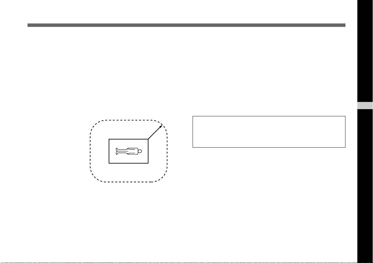
Important safeguards/notices for use in the medical
environments
1. All the equipments connected to this unit shall be certified
according to Standard IEC60601-1, IEC60950, IEC60065
or other IEC/ISO Standards applicable to the equipments.
2. When this unit is used together with other equipment in
the patient area*, the equipment shall be either powered
by an isolation transformer or connected via an additional
protective earth terminal to system ground unless it is
certified according to Standard IEC60601-1.
4. This equipment generates, uses, and can radiate
frequency energy. If it is not installed and used in
accordance with the instruction manual, it may cause
interference to other equipment. If this unit causes
interference (which can be determined by unplugging the
power cord from the unit), try these measures: Relocate
the unit with respect to the susceptible equipment. Plug
this unit and the susceptible equipment into different
branch circuit. Consult your dealer.
(According to Standard EN60601-1-2 and CISPR11, Class
B, Group 1)
GB
English
* Patient Area
R 1.5 m
3. The leakage current could increase when connected to
other equipment.
Caution
When you dispose of the unit or accessories, you must
obey the law in the relative area or country and the
regulation in the relative hospital.
3
(GB)
Page 4

Table of Contents
Chapter 1
Overview
Features .................................................................... 6
Location and Functions of Parts and Controls ..... 8
Front Panel/Top Panel/Bottom Panel..................... 8
Right Side Panel (Control Panel)........................... 9
Rear Panel ............................................................ 11
Chapter 2
Operation
Adjusting snd Setting with Menus ....................... 12
Menu Configuration............................................. 12
Operation through Menus .................................... 14
Function of Menus ............................................... 16
Initial Setting of the Menus ................................. 31
Shooting.................................................................. 32
Adjusting the Flange Focal Length...................... 32
Basic Shooting Procedure .................................... 35
Adjusting the Iris, Focus and Zoom..................... 36
Adjusting the Black Balance................................ 38
Adjusting the White Balance ............................... 39
Adjusting the Picture Tone in a Multi-Camera
System ............................................................ 41
Chapter 3
Installation and Connections
Installation .............................................................. 42
Applicable Lens ................................................... 42
Mounting the Lens ............................................... 43
Mounting a Microscope Adaptor ......................... 45
Mounting on a Tripod .......................................... 45
Mounting to a Wall or Ceiling ............................. 45
Basic System Connection ..................................... 47
Connecting to Video Equipment with Composite
Video Input Connectors.................................. 48
Connecting to Video Equipment with RGB or
S-Video Inputs................................................ 50
Connecting Two or More Cameras—Multi-Camera
System ............................................................ 51
Connecting to a Remote Control Unit .................. 52
Operating the Camera with the RM-C950 Remote
Control Unit ................................................... 53
Connecting to a Computer .................................... 54
Connections for Long Exposure Shooting.......... 55
Connections for Shooting Using a Flash............. 56
4 (GB)
Table of Contents
Page 5

Chapter 4
Appendix
Precautions............................................................. 57
Typical CCD Phenomena....................................... 58
List of Messages .................................................... 59
Specifications......................................................... 60
Optional Accessories ............................................ 64
Table of Contents
5
(GB)
Page 6

Chapter 1
Chapter 1
Overview
Features
High-quality images
• The high density 1/3 type, three-chip Exwave HAD
CCD2), containing some 380,000 (DXC-390) or 430,000
(DXC-390P) effective picture elements (pixels), offers
superior picture quality: 800 TV lines of high horizontal
resolution, high sensitivity of F8 at 2,000 lx, an excellent
signal-to-noise ratio of 62 dB (DXC-390) or 61 dB (DXC390P) and a low smear level.
• The adoption of the LSI digital signal processing
technology reproduces a finer, more detailed picture.
• DynaLatitude processing enables you to adjust contrast
finely according to the luminance signal level of each
picture element.
...........................................................................................................................................................................................................................................................
1) Exwave HADTM: Exwave Hole-Accumulated Diode
“Exwave HADTM” is a trademark of Sony Corporation.
TM1)
• The DCC+ (Dynamic Contrast Control plus) function
minimizes the phenomena whereby the whole screen turns
white or a part of the image becomes colorless when
shooting a very bright object.
• The Partial Enhance function enables you to adjust the
sharpness and tint of only a specified color.
Wide Range of Exposure Control
The AGC (Auto Gain Control) function and CCD IRIS
function automatically adjust a wide range of incoming light
levels. When the lighting condition is poor, the AGC
function automatically increases the gain up to 16 times.
When incoming light is excessive, the CCD IRIS function
automatically adjusts shutter speed to cut exposure to the
2) CCD: Charge-Coupled Device
3) “CCD IRISTM” is a trademark of Sony Corporation.
TM3)
6 (GB) Chapter 1 Overview
Page 7

equivalent of up to 10 aperture stops. When using the video
camera in a fixed location or for a microscope system, the
AGC, CCD IRIS and auto-iris controls automatically adjust
a wide range of incoming light levels. The desired AE
window can be set by using the AE AREA MANUAL
function.
Wide range of electronic shutter modes
The wide range of speeds for the electronic shutter
minimizes blurring in fast-moving objects and produces
acceptably bright still images of objects shot in poor light.
• Flickerless mode: This mode allows you to obtain
flickerless images shot even under fluorescent light.
• Clear scan mode: This mode reduces horizontal bands
appearing in computer displays when shooting the display
with the conventional video camera.
Versatile use with external equipment
• The video camera is equipped with three types of outputs:
composite, Y/C and RGB outputs. The camera offers a
high-quality picture on a connected monitor or VCR.
• The camera can be remotely controlled with the RM-C950
remote control unit (not supplied).
RS-232C interface
The camera can be controlled from a computer via the RS232C interface.
For details, contact your authorized Sony dealer.
Compact and lightweight
The camera is compact (56 × 50 × 128 mm (2 1/4 × 2 × 5 1/8
inches)) and very light (approx. 370 g (13 oz)), allowing
easy installation even where space is a problem.
Following are some sample applications:
• As a permanent fixture in theaters, concert halls, etc.
• As a bird’s-eye view camera for special events
• As a video conference system camera
• As a camera for microscopes
• As a rooftop weather-monitoring camera
• As a laboratory monitor camera
Chapter 1
Chapter 1 Overview 7
(GB)
Page 8
Location and Functions of Parts and Controls
Chapter 1
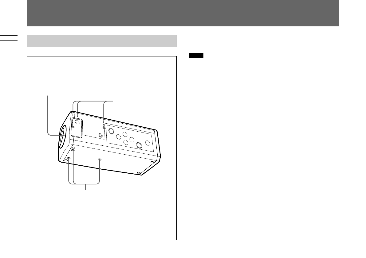
Front Panel/Top Panel/Bottom Panel
1 Lens mount
2 Screw holes (M3)
2 Screw holes (M3)
1 Lens Mount (C-mount)
Attach a C-mount lens or microscope adaptor.
Note
Be sure to use a lens whose projected part from the lens
mount surface is less than 4.3 mm. Mounting the lens with a
projected part greater than 4.3 mm may damage the internal
mechanism of the camera.
2 Screw holes
Use these holes (M3, depth: 4 mm (3/16 inches)) to attach the
supplied tripod adaptor to the camera for mounting the
camera on a wall, ceiling or tripod.
For how to install the tripod adaptor, see “Mounting on a
Tripod” on page 45.
8 (GB) Chapter 1 Overview
Page 9

Right Side Panel (Control Panel)
1 MENU button
Displays the MAIN menu on a monitor screen. Press again
to exit the menu. When a setting menu is displayed, press
this button to return to the MAIN menu.
For menu operations, see “Operation through Menus” on
page 14.
Chapter 1
1 MENU button
2 V/BLACK button
6 v button
7 B/FILE SELECT button
8 FLANGE BACK (flange focal
length) adjustment ring
3 b/ WHITE button
4 BARS button
5 ENTER button
2 V/BLACK (black balance) button
While the menu is displayed: Moves the menu cursor
upward. Also use this button for an AE window setting,
etc.
While the normal screen is displayed: Activates the
automatic black balance adjustment.
3 b/ WHITE (white balance) button
While the menu is displayed: Increases the setting value or
changes the setting. Also use this button for an AE
window setting, etc.
While the normal screen is displayed: Activates the
automatic white balance adjustment when MODE is set
to AWB in WHITE BALANCE menu.
Chapter 1 Overview 9
(GB)
Page 10

Location and Functions of Parts and Controls
4 BARS (color bars output) button
Outputs the color bar signal. Press again to revert to video
Chapter 1
signal output.
For monitor adjustment, contact your authorized Sony
dealer.
5 ENTER button
Selects a setting menu in the MAIN menu. Also use this
button for an AE window setting, etc.
6 v button
Moves the menu cursor downward. Also use this button for
an AE window setting, etc.
7 B/FILE SELECT button
While the menu is displayed: Decreases the setting value
or changes the setting. Also use this button for an AE
window setting, etc.
While the normal screen is displayed: Switches the user
preset file between A and B.
8 FLANGE BACK (flange focal length) adjustment
ring
Adjusts the flange focal length of a lens which is not
equipped with this function.
For details on flange focal length adjustment, see
“Adjusting the Flange Focal Length” on page 32.
10 (GB) Chapter 1 Overview
Page 11
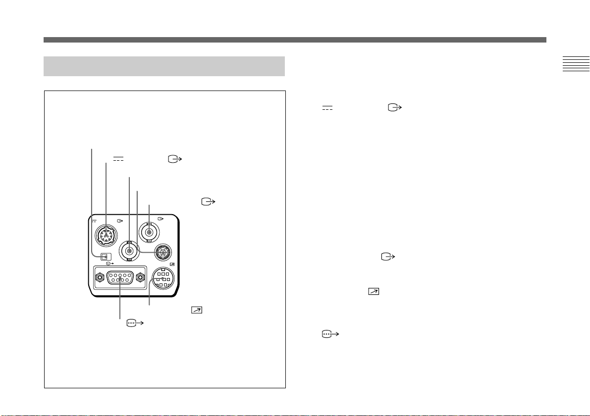
Rear Panel
1 MENU LOCK ON/OFF switch
2 DC IN/VBS connector
DC IN/VBS
MENU LOCK
OFF ON
3 TRIG IN connector
4 LENS connector
5 VIDEO OUT connector
VIDEO OUT
TRIG IN
RGB/SYNC
7 RGB/SYNC connector
LENS
REMOTE
6 REMOTE connector
1 MENU LOCK ON/OFF switch
When this switch is set to ON, the menu is not displayed on
the screen even if you press the MENU button.
2 DC IN/VBS (DC input/video signal output)
connector (12-pin)
Connects to the CMA-D2/D2MD/D2CE/D2MDCE camera
adaptor. Inputs the DC power and outputs the video signal.
3 TRIG IN connector (BNC type)
Connects to a commercially available slave unit by
converting to BNC type in strobe mode.
4 LENS connector (6-pin)
Connects to a lens control cable when attaching the zoom
lens especially designed for this camera.
5 VIDEO OUT connector (BNC type)
Outputs a composite video signal.
6 REMOTE connector (mini DIN 8-pin)
Connects to the RM-C950 remote control unit (not
supplied).
7 RGB/SYNC connector (D-sub 9-pin)
Outputs RGB signals and their respective sync signals.
Use the CCXC-9DB/CCXC-9DD/CCMC-9DS connecting
cable for the connections.
Chapter 1
Chapter 1 Overview 11
(GB)
Page 12
Chapter 2
Chapter 2
Operation
Adjusting and Setting with Menus
Camera operational settings can be changed through simple
adjustment of the settings on the on-screen menus. Settings
can be adjusted to get the best possible results for the given
shooting conditions or to enhance the image with special
effects.
Menu Configuration
Before starting menu operation, make sure that the MENU
LOCK ON/OFF switch on the rear panel is set to OFF.
To display a menu, press the MENU button on the right side
panel. The MAIN menu is displayed on the monitor screen.
The setting menu will be displayed by selecting the desired
setting menu item with the V or v button and pressing the
ENTER button.
12 (GB) Chapter 2 Operation
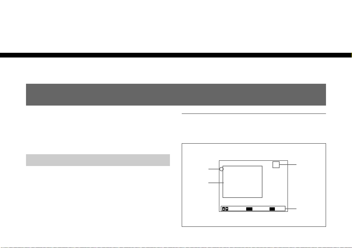
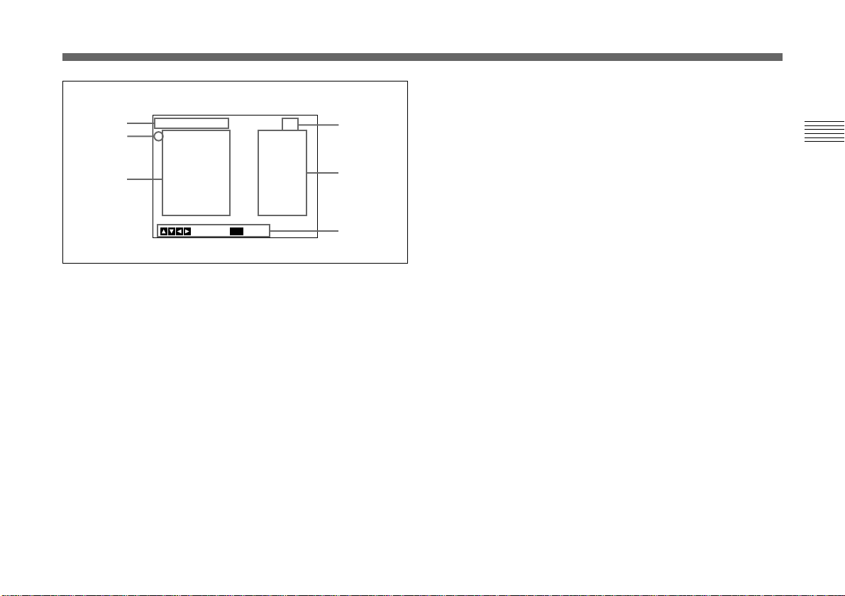
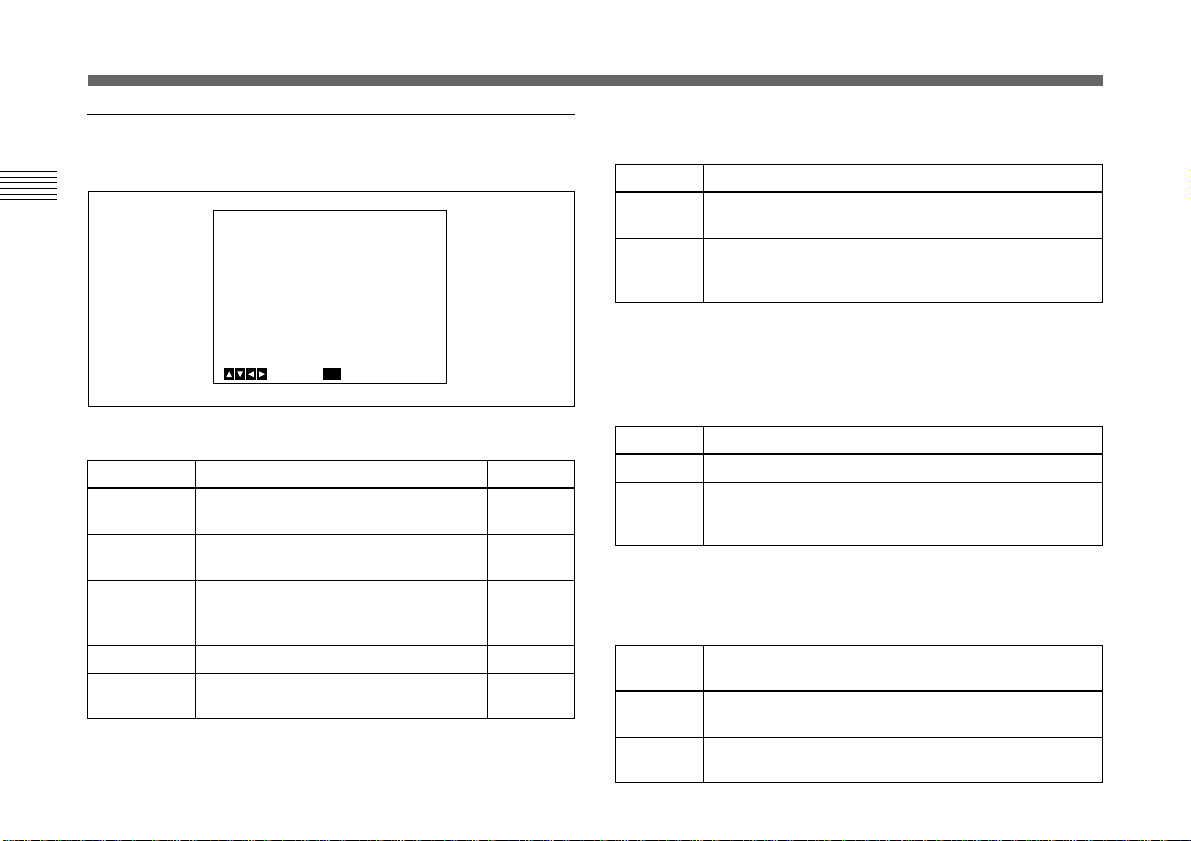
About on-screen menus
This section explains how to read the on-screen menu before
starting menu operation.
MAIN menu
<MAIN>
>EXPOSURE
1
CONTRAST
WHITE BALANCE
ENHANCER
2
GENERAL
SYSTEM
SCENE FILE
ENTER
Next
[A]
MENU
3
ExitSelect
4
Page 13
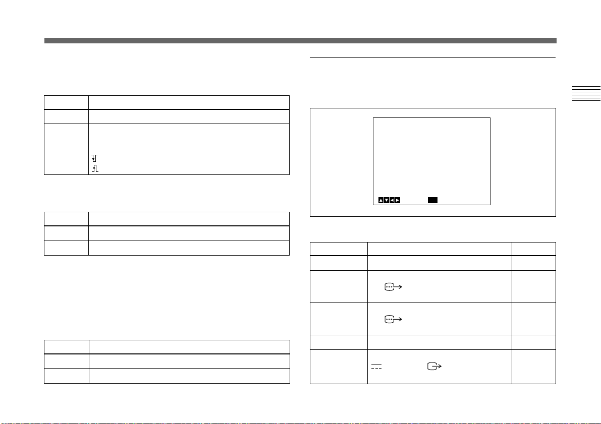
Setting menu
5
1
6
<EXPOSURE>
>GAIN
STEP
SHUTTER
LENS
IRIS
AE LEVEL
AE AREA
MENU
REMOTE
BackSelect
[A]
STEP
0dB
OFF
AUTO
+_
MULTI
4 Operational message
Indicates how to operate the currently displayed menu.
3
5 Setting menu
Indicates the currently selected setting menu.
7
Chapter 2
6 Setting items
0
Indicates the items that can be adjusted in each setting
menu.
4
Select the item by moving the cursor beside it with the V or
v button.
1 Cursor
Selects a setting menu or setting item.
Move the cursor up or down using the V or v button.
2 Setting menu items
When you select the desired item with the V or v button
and press the ENTER button, the setting menu for
adjustment and setting is displayed.
3 User preset file
You can store two types of preset adjustments into files A
and B. Indicates the currently selected preset file (A or B).
7 Set values
The currently set values are displayed.
Change the values using the B or b button.
Chapter 2 Operation 13
(GB)
Page 14
Adjusting and Setting with Menus
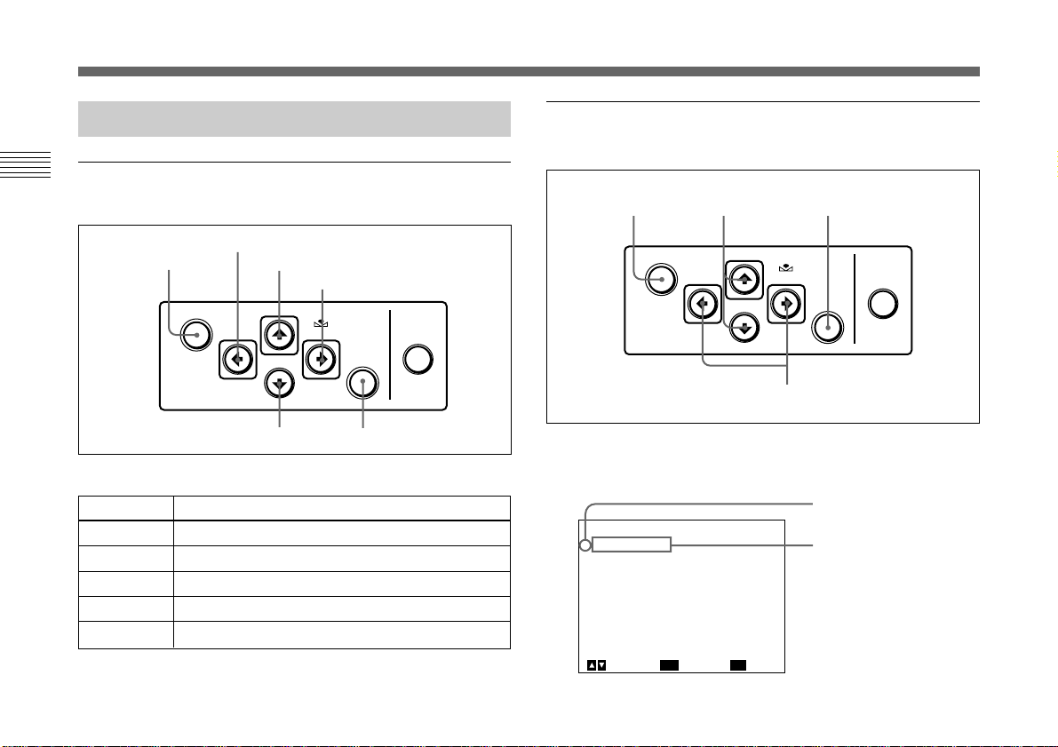
Operation through Menus
Menu operation buttons
Chapter 2
Operate the menu with the buttons on the right side panel.
MENU button
The following table shows the functions of the buttons.
Button
MENU
V button
v button
B button
b button
B button
V button
b button
MENU
Function
Displays the MAIN menu.
Moves the cursor upward.
Moves the cursor downward.
Changes the setting/decreases the value.
Changes the setting/increases the value.
FILE
SELECT
BLACK
v button
WHITE
ENTER
ENTER button
BARS
Menu operation procedure
To change the settings on the menu, proceed as follows.
1 2,3 2
MENU
FILE
SELECT
BLACK
WHITE
BARS
ENTER
4
1 Press the MENU button.
The MAIN menu appears.
Cursor
<MAIN>
>EXPOSURE
CONTRAST
WHITE BALANCE
ENHANCER
GENERAL
SYSTEM
SCENE FILE
ENTER
Next
[A]
MENU
Setting menu
ExitSelect
14 (GB) Chapter 2 Operation
Page 15
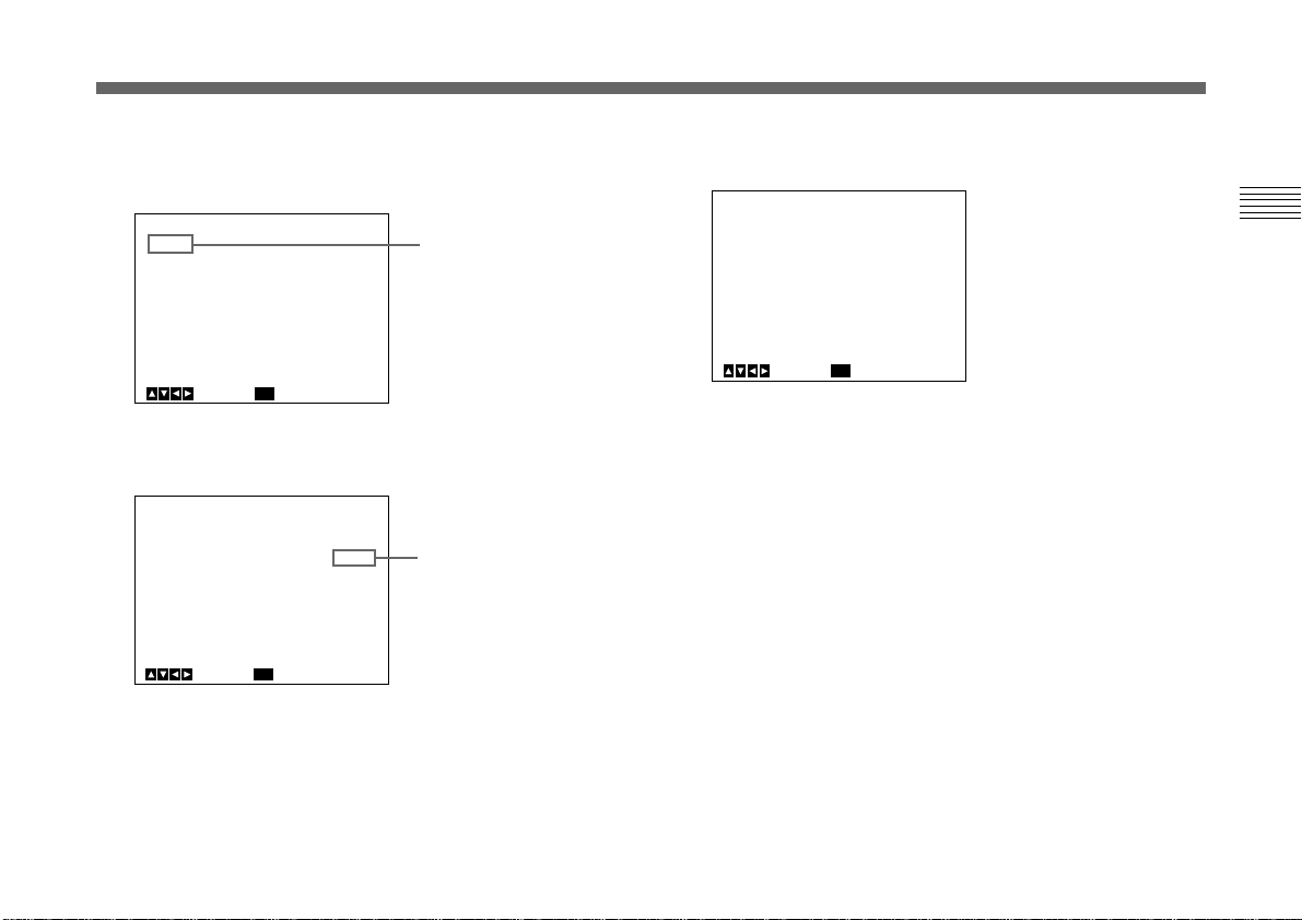
2 Move the cursor to the menu item to be set by pressing
<EXPOSURE>
GAIN
STEP
>SHUTTER
SPEED
LENS
IRIS
AE LEVEL
AE AREA
[A]
STEP
0dB
STEP
OFF
REMOTE
AUTO
0
MULTI
BackSelect
MENU
+_
the V or v button, then press the ENTER button.
The setting menu is displayed.
4 Change the value by pressing the B or b button.
Holding down the button changes the value quickly.
3 Move the cursor to the item to be adjusted by pressing
<EXPOSURE>
>GAIN
STEP
SHUTTER
LENS
IRIS
AE LEVEL
AE AREA
MENU
the V or v button.
<EXPOSURE>
GAIN
STEP
>SHUTTER
LENS
IRIS
AE LEVEL
AE AREA
MENU
REMOTE
BackSelect
REMOTE
BackSelect
[A]
STEP
0dB
OFF
AUTO
+_
MULTI
[A]
STEP
0dB
OFF
AUTO
+_
MULTI
0
0
Setting item
Set value
To reset to the initial set value
Select the item to be reset, then press the B and b buttons
simultaneously.
For the initial set value on each item, see “Initial Setting of
the Menus” on page 31.
To return to the normal screen
Press the MENU button while the MAIN menu is displayed.
While each setting menu is displayed, press the MENU
button to return to the MAIN menu, then press it again to
return to the normal screen.
Chapter 2 Operation 15
(GB)
Chapter 2
Page 16
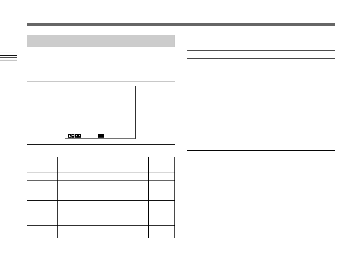
Adjusting and Setting with Menus
Function of Menus
EXPOSURE menu
Chapter 2
Adjusts the items relating to exposure, such as gain and
shutter mode.
<EXPOSURE>
>GAIN
STEP
SHUTTER
LENS
IRIS
AE LEVEL
AE AREA
MENU
Setting items on the EXPOSURE menu
Setting item
GAIN
STEP
SHUTTER
LENS
IRIS
AE LEVEL
AE AREA
Contents of setting
Adjusts video gain.
Sets gain level.
Sets the modes for the electronic
shutter.
Sets the iris mode.
Adjusts the iris automatically or
manually.
Finely adjusts the focusing point of auto
exposure adjustment.
Sets the AE window in AGC, CCD IRIS
or auto iris adjustment mode.
REMOTE
BackSelect
[A]
STEP
0dB
OFF
AUTO
+_
MULTI
0
Ref. page
16
16
16
18
19
19
19
GAIN
Adjusts the video gain.
Selection
STEP
AGC
HYPER
Function
Sets the video gain to the desired level. Use this
setting for shooting in an extremely dark place
where even fully opening the lens iris still does not
produce an acceptably bright image. The gain level
can be set in the range from 0 to 24 dB in units of 1
dB.
Automatic gain control. Automatically adjusts the
gain according to the brightness of the object to be
shot. This setting is useful for shooting when lighting
conditions may change.
You can select the maximum gain level to be
adjusted to 6, 12, 18 or 24 dB with the LIMIT setting.
Increases the video gain to about 30 dB. This
setting is useful when the lighting condition is very
dark.
SHUTTER (electronic shutter)
Selects the electronic shutter modes.
This function enables you to obtain blur-free images of fastmoving objects and acceptably bright still images of objects
shot in poor lighting conditions.
16 (GB) Chapter 2 Operation
Page 17
Selection
OFF
STEP
Function
Any electronic shutter mode does not function.
Sets the shutter speed to any of 15 steps in long-
exposure mode and 11 steps in high-speed mode.
Select SPEED and set the shutter speed from
among the following values:
Long-exposure mode: 0.1, 0.2, 0.3, 0.5, 1.0, 1.5,
2.0, 2.5, 3.0, 3.5, 4.0, 5.0, 6.0, 7.0, and 8.0 sec.
To set the speed, display OFF by pressing the B
and b buttons simultaneously, then select the
desired value by pressing the b button. Each press
changes the speed in the order as shown above.
High-speed mode: FL (flickerless), 1/125, 1/250,
1/500, 1/1000, 1/2000, 1/4000, 1/10000, 1/20000,
1/40000, 1/100000
To set the speed, display OFF by pressing the B
and b buttons simultaneously, then select the
desired value by pressing the B button. Each press
changes the speed in the order as shown above.
When using the camera in a 50 Hz lighting area
(DXC-390) or in a 60 Hz lighting area (DXC-390P),
the FL setting offers flickerless images even under
fluorescent light.
Selection
VARIABLE
Function
Use for fine adjustment of the video output level in
long exposure mode (low-speed mode) or in clear
scan mode (high-speed mode).
Chapter 2
Long exposure mode
You can set the SPEED value in units of 1 frame.
For example, if you set to 50 frames (about 1.7
seconds), the video signal produced during this set
time is output in the form of one complete frame at
intervals of about 1.7 seconds. These pictures,
which contain 50 frames of video information, are
much brighter than normal one-frame images. This
mode is useful for shooting a poorly illuminated
object in a dark place.
To set the shutter speed
1 Display OFF by pressing the B and b buttons
simultaneously.
2 Select the SPEED value by pressing the b
button. Each time you press the button, the value
changes in units of 1 frame.
To convert the value into the shutter speed
Example: When the value is set to 5 frames
5 × 1/30 = 0.1666 seconds (DXC-390)
5 × 1/25 = 0.2000 seconds (DXC-390P)
Notes
• Do not use AGC, CCD-IRIS, ATW, DCC+ and
DYNALATITUDE functions in long exposure
mode.
• When you set the shutter speed to 1 second or
higher, set the gain level to 0 dB.
(Continued)
Chapter 2 Operation 17
(GB)
Page 18

Adjusting and Setting with Menus
Selection
VARIABLE
(Continued)
Chapter 2
CCD-IRIS
Function
Clear scan mode
You can set the shutter speed in units of 1H
(horizontal scanning time: 63.56 µs for DXC-390,
64.00 µs for DXC-390P).
Select SPEED, then select the value from 1/525H to
262/525H (DXC-390) or 1/625H to 312/625H (DXC390P). This mode can be used for shooting
computer displays with reduced horizontal bands
appearing across the display screen.
To set the shutter speed
1 Display OFF by pressing the B and b buttons
simultaneously.
2 Select the SPEED value by pressing the b button
while observing the noise on the monitor screen
so that you can obtain the image with minimum
noise. Each time you press the button, the value
changes in units of 1H.
To convert the value into the shutter speed
Example: When the value is set to 250H
DXC-390:
250 × 63.56 µs (1H) + 34.9 µs (constant)
= 15924.9 µs = Approx. 0.016 seconds
DXC-390P:
250 × 64.00 µs (1H) + 35.0 µs (constant)
= 16035.0 µs = Approx. 0.016 seconds
Automatically adjusts the luminance level for
optimum output level. When incoming light is
excessive, this function automatically adjusts the
shutter speed to cut exposure equivalent to up to 10
aperture stops.
Selection
CCD-IRIS
(Continued)
Function
For example, this function is useful for microscope
applications. When shooting with a microscope not
equipped with the auto-iris lens, the luminance level
that is just right for the human eye is often too bright
for the video camera.
When CCD-IRIS is selected, the electronic shutter
automatically decreases excessive incident light to
an appropriate level for the video camera. This
function is also useful for cutting out excessive
incident light that is not cut out by the auto-iris lens
in scenes containing very bright patches (such as
snow, or sea water reflecting sunlight).
You can select the highest limit value of the variable
range of the shutter speed. Select LIMIT, then set
the speed to 1/250, 1/500, 1/1000, 1/2000, 1/4000,
1/10000, 1/20000,1/40000 or 1/100000.
Note
You cannot use CCD-IRIS mode when using a lens
that automatically adjusts the iris control according
to the video signal input.
LENS
Selects the iris mode.
Selection
VIDEO
REMOTE
Function
Select when you use a lens that automatically
adjusts the iris according to the input video signal.
Select AE LEVEL, then adjust the auto exposure
focusing point in the range from –127 to +127.
Select when you use a lens that adjusts the iris
according to the DC power supplied.
18 (GB) Chapter 2 Operation
Page 19

IRIS
Appears when you set LENS to REMOTE.
Selects how to adjust the iris. You can select AUTO or
MANUAL.
AUTO: Adjusts the iris automatically.
MANUAL: Adjusts the iris with the IRIS control on the
RM-C950 remote control unit.
Selection
AE LEVEL
AE AREA
Function
Sets auto exposure focusing point in the range from
–127 to +127.
Sets the AE (Auto Exposure) window when the
camera is set to AGC, CCD IRIS or auto-iris control
mode.
MULTI: Divides the screen into 9 sections and
adjusts auto exposure according to the
luminance level in each section. Normally set to
this position.
LARGE, MID, SPOT and SLIT: Displays the
following AE windows and adjusts auto exposure
according to the luminance level in each area.
LARGE
MID
SLIT
SPOT
Selection
AE AREA
(Continued)
Function
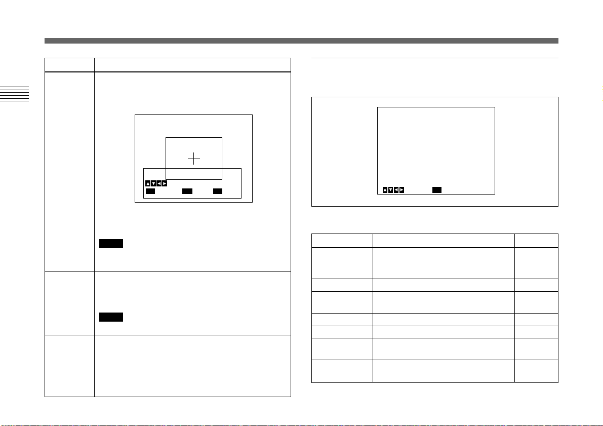
MANUAL: Sets the AE window with the desired size
and position on the screen.
Follow the steps below.
1 Select MANUAL and press the ENTER button.
Cross
cursor
Set Top-Left Point
Move Cross Cursor
MENU
Cancel
ENTER
Next
2 Move the cross cursor appearing at the left top
corner with the B, b, V or v button to set the
upper and left side size, then press the ENTER
button.
Set Bottom-Right Point
Move Cross Cursor
MENU
Cancel
ENTER
Next
BARS
Back
Cross
cursor
Chapter 2
(Continued)
Chapter 2 Operation 19
(GB)
Page 20
Adjusting and Setting with Menus
<CONTRAST>
>EFFECT
KNEE POINT
BLACK STRETCH
GAMMA
LEVEL
MASTER PEDESTAL
R. PEDESTAL
B. PEDESTAL
Select
[A]
MANUAL
MID
0
ON
0
0
0
0
Back
MENU
+_
+_
+_
+_
+_
Selection
AE AREA
(Continued)
Chapter 2
AE SPEED
AE DETECT
20 (GB) Chapter 2 Operation
Function
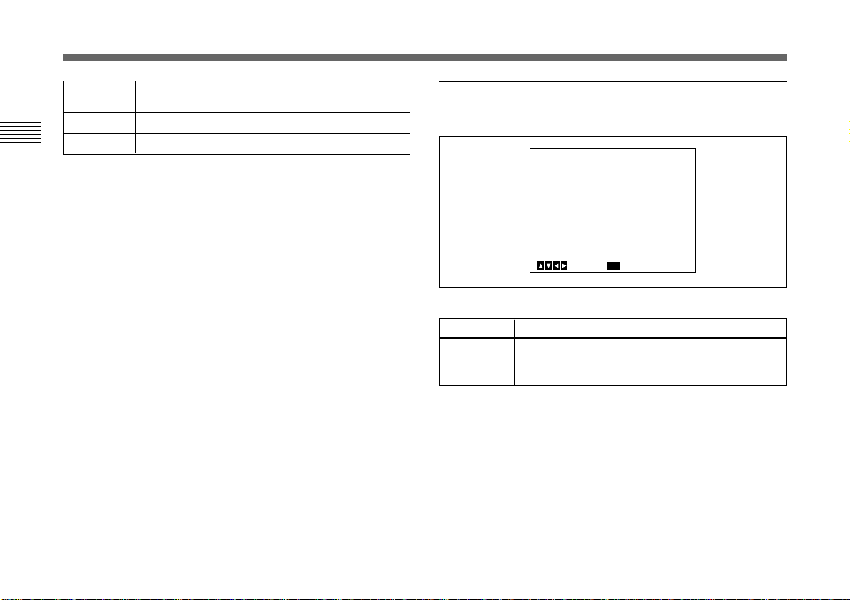
3 Move the cross cursor appearing at the right
bottom corner with the B, b, V or v button to set
the lower and right side size, then press the
ENTER button.
Move Window
Move Cross Cursor
MENU
Cancel
ENTER
Fix
BARS
Back
4 Move the AE window to the desired position with
the B, b, V or v button, then press the ENTER
button.
Note
To cancel the setting before completing the
procedure, press the MENU button.
Sets auto exposure focusing speed in AGC, CCD
IRIS or auto-iris control mode.
Selects from MID (normal speed), FAST (fast speed)
and SLOW (slow speed).
Note
If lens hunting occurs, adjust with AE SPEED.
Selects the detection method of the luminance level
of the selected AE window.
AVERAGE: Selects to detect the average luminance
level of the whole AE window.
PEAK: Selects to detect the part with the highest
luminance level.
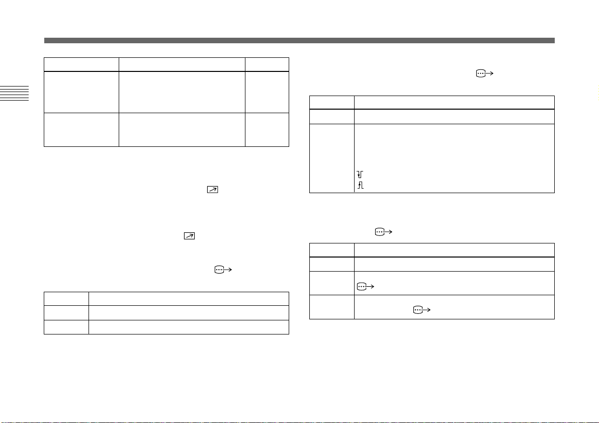
CONTRAST menu
Adjusts the contrast of the image.
Setting items in the CONTRAST menu
Setting item
EFFECT
KNEE POINT
BLACK
STRETCH
GAMMA
LEVEL
MASTER
PEDESTAL
R./B.
PEDESTAL
Contents of setting
Adjusts the picture contrast in
accordance with the incident
luminance level.
Sets the knee point.
Adjusts the luminance of a dark
portion of the screen.
Activates gamma compensation.
Adjusts the gamma level.
Sets the pedestal level of the output
signal.
Finely adjust the pedestal level.
Ref. page
21
21
21
21
21
21
22
Page 21

EFFECT
Selects the setting suitable for the incident luminance levels.
Selection
MANUAL
DCC+
DYNALATITUDE
Function
Selects KNEE POINT setting or BLACK STRETCH.
KNEE POINT
Sets the knee point according to the incoming light
levels.
OFF: Knee processing does not function.
HIGH: Sets the knee point to the highest level.
MID: Normally, select this position.
LOW: Sets the knee point to the lowest level.
BLACK STRETCH
Adjusts the luminance of the dark portion of the
screen.
You can set the value within the range from –10 to
+10. The higher the setting, the brighter the screen.
When shooting a very bright object, the whole
screen may white out or a part of the image may be
colorless. This setting minimizes these phenomena.
Adjusts the contrast according to the luminance
level of each picture element. The setting is useful
for shooting scenes mixed with bright and dark
parts.
You can set the level within the range from –10 to
+10.
GAMMA
Activates gamma compensation.
Selection
OFF
ON
Function
Outputs the video signal linearly without gamma
compensation. Use this setting when you want to
produce images for image processing or image
analysis.
Compensates the reproduction characteristics of a
cathode-ray tube of a monitor to produce naturaltone image.
Select LEVEL, then adjust so that you can obtain
natural-tone image. Adjustable range is from –10 to
+10.
MASTER PEDESTAL
The pedestal levels of the G, B and R output signals can be
adjusted simultaneously.
Adjusts the darkness level of the black part of the image.
Use this function to bring out details in heavily shaded
areas. The adjustable range is from –127 to +127. Normally
set to ±0.
Use of a waveform monitor allows easier adjustment.
(Continued)
Chapter 2
Chapter 2 Operation 21
(GB)
Page 22
<WHITE BALANCE>
>MODE
R. PAINT
B. PAINT
[A]
AWB
0
0
+_
+_
Select Back
MENU
Adjusting and Setting with Menus
Adjusting
direction
+
–
Chapter 2
R. (red) PEDESTAL, B. (blue) PEDESTAL
Use these items to finely adjust the pedestal level of each
color. Adjust while watching the monitor screen. The items
can be finely adjusted within the range from –127 to +127.
Effect
The whole screen becomes whiter.
The whole screen becomes blacker.
WHITE BALANCE menu
Adjusts the white balance.
Setting items in the WHITE BALANCE menu
Setting item
MODE
R./B. PAINT
Contents of setting
Selects the white balance modes.
Finely adjusts the white balance (AWB,
ATW).
Ref. page
23
23
22 (GB) Chapter 2 Operation
Page 23

MODE
Selects the white balance modes.
Selection
AWB
ATW
NORMAL
or ATW
WIDE
Function
Adjusts the white balance atutomatically (auto white
balance).
When this item is selected, R. PAINT and B. PAINT
are displayed. Use these items for fine adjustment.
Adjust them while watching the monitor screen.
R. PAINT: Finely adjusts the red in the range from
–100 to +100.
B. PAINT: Finely adjusts the blue in the range from
–100 to +100.
For details, see “Adjusting the White Balance” on page 39.
Activates auto-tracing white balance. This mode is
suitable for shooting when the light source changes.
The white balance is automatically adjusted as the
color temperature changes.
Normally, set to ATW NORMAL.
The ATW WIDE setting can cope with a wider range of
color temperature changes.
When these items are selected, R. PAINT, B. PAINT,
AREA and SPEED are displayed. Use these items for
fine adjustment. Adjust them while watching the
monitor screen. The adjusted values are stored in
memory other than AWB values.
R. PAINT: Finely adjusts the red in the range from
–10 to +10.
B. PAINT: Finely adjusts the blue in the range from
–10 to +10.
Selection
ATW
NORMAL
or ATW
WIDE
(Continued)
MANUAL
3200K
5600K
Function
AREA: A detecting window appears on the monitor
screen. Normally set to NORMAL to detect the
average luminance level on the whole screen. If
you want to display the desired window, set to
MANUAL and follow the steps below.
1 Press the ENTER button.
2 Move the left top cross cursor with the B, b, V or
v button to set the upper and left side size, and
press the ENTER button.
3 Move the right bottom cross cursor with the B, b,
V or v button to set the lower and right side size,
and press the ENTER button.
4 Move the window to the desired position on the
screen with the B, b, V or v button, and press
the ENTER button.
SPEED: Sets the focusing speed. You can select
SLOW (slow speed), MID (normal speed) or FAST
(fast speed).
Use for manual adjustment of white balance.
When this item is selected, R. GAIN and B. GAIN are
displayed. Adjust them while watching the monitor
screen.
R. GAIN: Finely adjusts the red gain in the range from
–127 to +127.
B. GAIN: Finely adjusts the blue gain in the range
from –127 to +127.
Selects for indoor shooting. (Color temperature:
3200K)
Selects for outdoor shooting. (Color temperature:
5600K)
Chapter 2
Chapter 2 Operation 23
(GB)
Page 24

Adjusting and Setting with Menus
ENHANCER menu
Adjusts the sharpness of the image outline and the color
tone (hue).
Chapter 2
<ENHANCER>
>DETAIL
LEVEL
FREQUENCY
LINEAR MATRIX
MODE
TARGET COLOR
MENU
Select Back
Setting items in the ENHANCER menu
Setting item
DETAIL
LEVEL
FREQUENCY
LINEAR MATRIX
MODE
TARGET COLOR
Contents of setting
Enables or disables to adjust the
sharpness of the image outline.
Adjusts the sharpness of the image
outline.
Adjusts the sharpness of the
detailed image outline.
Enables or disables processing of a
color matrix.
Finely adjusts the color tone.
Specifies the color for DETAIL or
LINEAR MATRIX adjustments.
[A]
ON
+_
MID
STANDARD
ON
ALL
0
Ref. page
24
24
24
25
25
25
DETAIL
Enables or disables adjustment of the sharpness of the image
outline.
Selection
ON
OFF
Function
Enables adjustment of the sharpness of the image
outline.
Disables adjustment of the sharpness of the image
outline.
When you set DETAIL to ON, LEVEL and FREQUENCY
are displayed.
Adjust the sharpness of the image outline in accordance with
your shooting purpose and your taste.
Selection
LEVEL
FREQUENCY
Function
Adjusts the level in the range from –127 to +127.
The lower level decreases the sharpness of the image
outline and makes the image softer.
The higher level increases the sharpness of the image
outline and makes the image sharper.
Selects the frequency level with which the image
outline is adjusted from LOW (lower frequency level),
MID (middle frequency level) or HIGH (higher
frequency level). Higher setting provides a sharper
outline of detailed images.
24 (GB) Chapter 2 Operation
Page 25
LINEAR MATRIX
Processes an image with a color matrix to change the
chroma saturation and hue in order to reproduce natural
color.
Selection
ON
OFF
Function
Corrects the color to reproduce natural color.
Color correction does not function. Use when you want
to process the image.
When you set LINEAR MATRIX to ON, MODE is
displayed. You can adjust the color suitable for an object.
When you set MODE to MANUAL, R. PAINT, G. PAINT
and B. PAINT appear.
TARGET COLOR
Select when adjusting DETAIL or LINEAR MATRIX for a
specific color.
Selection
ALL
IN
OUT
Function
Adjusts DETAIL or LINEAR MATRIX for the whole
image. Normally, set to this position.
Adjusts DETAIL or LINEAR MATRIX for a specific
color.
With the RANGE setting you can finely adjust the area
in the range from –10 to +10.
Adjusts DETAIL or LINEAR MATRIX for colors other
than a specified one.
Chapter 2
Selection
STANDARD
R ENHANCE
B ENHANCE
G ENHANCE
MANUAL
Function
Normally, select this setting.
Enhances the red.
Enhances the blue.
Enhances the green.
Adjusts each color finely.
R. PAINT: Finely adjusts the red in the range from –30
to +30.
G. PAINT: Finely adjusts the green in the range from
–30 to +30.
B. PAINT: Finely adjusts the blue in the range from
–30 to +30.
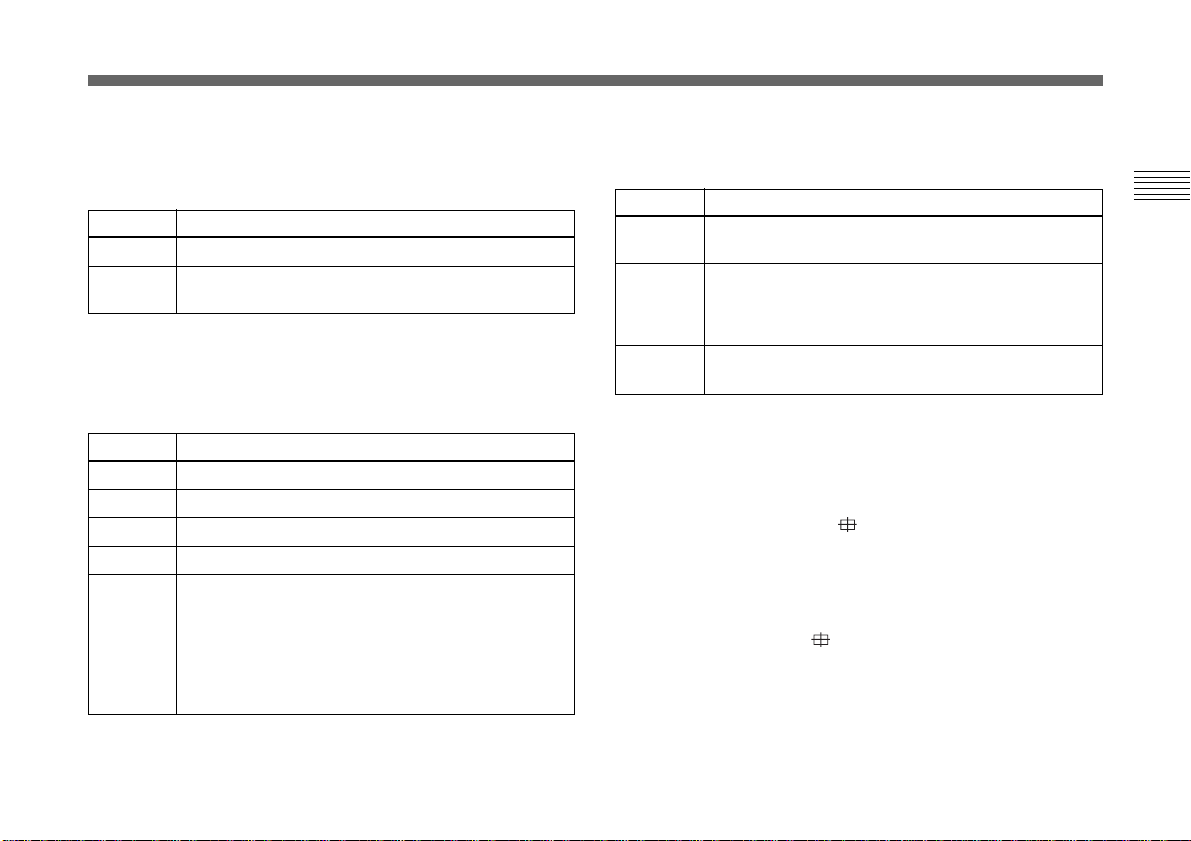
How to specify a color
1 Select IN or OUT and press the ENTER button.
2 Move the cross cursor ( ) appearing in the center of
the screen to the desired color with the B, b, V or v
button so that the cross cursor square covers the desired
color, then press the ENTER button.
When you select IN, you can adjust the color indicated
by the cross cursor ( ).
When you select OUT, you can adjust colors other than
that with the cross cursor.
Chapter 2 Operation 25
(GB)
Page 26
Adjusting and Setting with Menus
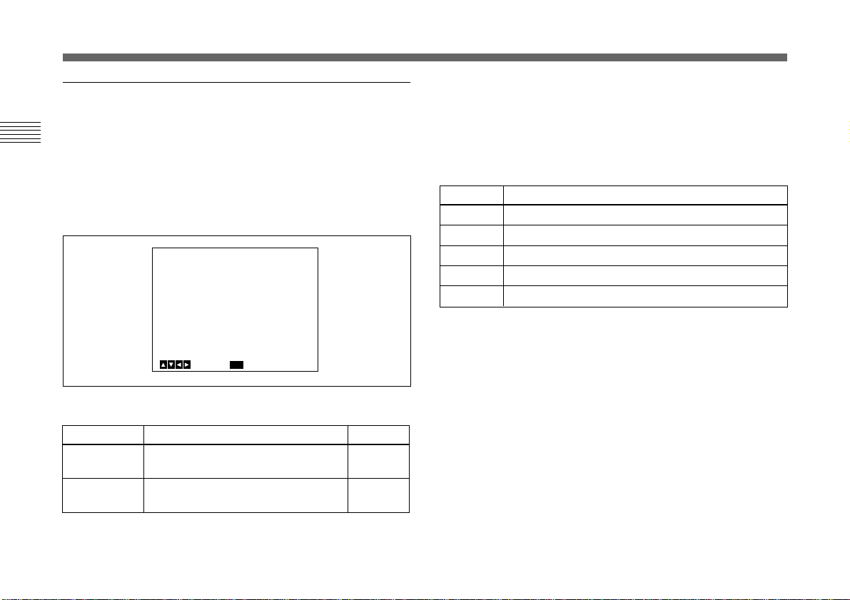
GENERAL menu
Sets the general items.
Chapter 2
Setting items in the GENERAL menu
Setting item
CCD MODE
SHADING
COMP.
TRIGGER
NEGA
FLICKER
CANCELLER
<GENERAL>
>CCD MODE
SHADING COMP.
TRIGGER
NEGA
FLICKER CANCELLER
MENU
Select Back
Contents of setting
Selects the CCD read-out mode.
Eliminates color at the top and bottom
of the screen.
Sets the polarity when connecting a
slave unit to synchronize with a
stroboscope.
Reverses the output image to negative.
Reduces flicker when SHUTTER is set
to CCD IRIS or OFF.
[A]
FIELD
OFF
OFF
OFF
OFF
Ref. page
26
26
27
27
27
CCD MODE
Selects the CCD read-out mode.
Selection
FIELD
FRAME
Function
Accumulates charges in field units. Use to shoot a
moving object.
Accumulates charges in frame units. Provides the
image with the highest possible vertical resolution.
Use to shoot a still object.
SHADING COMP. (Shading compensation)
Eliminates green or magenta color which may appear at the
top or bottom of the screen, when the camera is used with an
optical instrument.
Selection
OFF
ON
Function
Color elimination does not function.
If green or magenta color appears at the top or bottom
of the screen when the camera is attached to a
microscope, etc., select this setting.
When SHADING COMP. is set to ON, LEVEL is
displayed. Adjust while watching the screen so that the color
is eliminated. Adjustable range is from –127 to +127.
Adjusting
direction
+
–
Effect
Green at the top and magenta at the bottom will be
eliminated.
Magenta at the top and green at the bottom will be
eliminated.
26 (GB) Chapter 2 Operation
Page 27
TRIGGER
<SYSTEM>
>BAUD RATE
D-SUB VIDEO
D-SUB SYNC
RGB SYNC
12P CONNECTOR
[A]
9600
VBS
C.SYNC
G
IN
Select Back
MENU
Set when you use a slave unit connected to the TRIG IN
connector and synchronize the camera with a stroboscope.
Selection
OFF
ON
Function
Select when you do not connect a slave unit.
Select when you connect a slave unit.
Select POLARITY, and set it to the same polarity as
the input pulse signal.
: Falling edge
: Rising edge
NEGA
Reverses the output image to negative/positive.
SYSTEM menu
Sets the items relating to the system of the camera and
selection of output signals.
Chapter 2
Selection
OFF
ON
FLICKER CANCELLER
When using the camera in a 50 Hz lighting area (DXC-390)
or in a 60 Hz lighting area (DXC-390P), you can obtain
images with less flicker under fluorescent light even when
SHUTTER is set to CCD IRIS or OFF. Set this item to OFF
when you want to set NEGA to ON.
Selection
OFF
ON
Function
Outputs the image normally.
Outputs the image reversed to negative/positive.
Function
Disables the FLICKER CANCELLER function.
Reduces flicker.
Setting items in the SYSTEM menu
Setting item
BAUD RATE
D-SUB VIDEO
D-SUB SYNC
RGB SYNC
12P
CONNECTOR
Contents of setting
Selects the baud rate.
Switches the video signal output from
the RGB/SYNC connector (Dsub 9-pin).
Switches the sync signal output from
the RGB/SYNC connector (Dsub 9-pin).
Adds a sync signal to the RGB output.
Switches the input and output of the
DC IN/VBS connector and
selects the output signal.
Chapter 2 Operation 27
Ref. page
28
28
28
28
29
(Continued)
(GB)
Page 28
Adjusting and Setting with Menus
Setting item
(VBS lock)
H. PHASE*
SC. PHASE ROUGH*
Chapter 2
SC. PHASE FINE*
(HD/VD lock)
H. PHASE*
* Displayed only when an external sync signal is input.
Contents of setting
Adjusts the horizontal phase and
SC (subcarrier) phase during
external synchronization (with
VBS signal input).
Adjusts the horizontal phase
during external synchronization
(with HD/VD signal input).
BAUD RATE
Switches the baud rate of the REMOTE connector at the
rear panel.
Sets to any of 19200, 9600, 4800, 2400 and 1200.
Normally, set to 9600 when the RM-C950 remote control
unit is connected to the REMOTE connector.
D-SUB VIDEO
Switches the video signal output from the RGB/SYNC
connector (D-sub 9-pin) at the rear panel.
Selection
VBS
Y/C
Function
Outputs VBS signal.
Outputs Y/C signal.
Ref. page
29
30
D-SUB SYNC
Switches the sync signal output from the RGB/SYNC
connector (D-sub 9-pin) at the rear panel.
Selection
C.SYNC
WEN
Function
Outputs the composite sync signal.
Outputs the WEN signal. When connecting peripheral
equipment, the signal is used as trigger pulse output to
the equipment.
Select the polarity of the WEN signal with the
POLARITY setting.
: Negative
: Positive
RGB SYNC
Adds a sync signal to the G signal or R, G and B signals
output from the RGB/SYNC connector.
Selection
OFF
G
RGB
Function
No sync signal is added to an output signal.
Adds a sync signal to the G signal output from the
RGB/SYNC connector.
Adds sync signals added to the G, B and R signals
output from the RGB/SYNC connector.
28 (GB) Chapter 2 Operation
Page 29

12P CONNECTOR
Switches the input and output of the DC IN/VBS
connector (12-pin). Selects the output signal from this
connector when OUT is selected.
Selection
IN
OUT
Function
Functions as the input connector.
Functions as the output connector.
Select the output signal with the SIGNAL setting.
HD/VD: Outputs the HD/VD signal.
C. SYNC: Outputs the composite sync signal.
VBS lock
Appears only when an external reference sync signal (VBS
signal) is input. Adjusts the horizontal phase and SC
(subcarrier) phase to synchronize the camera operation with
the reference signal.
Selection
H.PHASE
SC.PHASE
ROUGH
SC.PHASE
FINE
Function
Adjusts the horizontal phase within the range from
–20 to +127.
Roughly adjusts the subcarrier phase by setting to 0°
or 180°.
Finely adjusts the subcarrier phase within the range
from –127 to +127.
HD/VD lock
Appears only when an external reference sync signal (HD/
VD signal) is input. Adjusts the horizontal phase to
synchronize the camera operation with the reference signal.
Select H.PHASE, then adjust the level within the range from
–20 to +127.
Chapter 2
Chapter 2 Operation 29
(GB)
Page 30
Adjusting and Setting with Menus
SCENE FILE menu
Sets the preset menu settings.
The camera has two memory files (A or B) for storing the
Chapter 2
menu settings. You can store a different type of setting into
each file, and switch to the file most suitable for the
shooting conditions quickly. The currently selected memory
file is shown in the upper right corner of the on-screen
menu.
<SCENE FILE>
>FILE SELECT
LOAD
MENU
Select Back
Setting items in the SCENE FILE menu
Setting item
FILE SELECT
LOAD
Contents of setting
Selects the file into which you store
the setting.
Selects the type of setting to be
stored, and loads it.
[A]
A
Ref. page
30
30
FILE SELECT
Selects the file A or B.
LOAD
Sets the setting to be stored into the file which you select
with FILE SELECT, and stores the setting.
Selection
STANDARD
MICROSCOPE
FULL AUTO
STROBE
FILE B (or A)
Type of setting
Suitable for a camera used as a permanent fixture.
Suitable for a camera for a microscope.
Automatically adjusts settings.
Suitable for stroboscopic shooting.
When copying the settings between two files.
Storing the setting
1 Select A or B into which the setting is stored in the
FILE SELECT setting.
2 Press the V or v button to select LOAD.
3 Press the B or b button to select the desired setting to
be stored, and press the ENTER button.
“Overwrite OK?” appears.
4 Press the ENTER button.
If you do not want to store the setting, press the MENU
button.
30 (GB) Chapter 2 Operation
Page 31

Initial Setting of the Menus
If you want to reset the settings and values to the initial
settings, press the B and b buttons simultaneously.
Setting menu
EXPOSURE
CONTRAST
Setting item
GAIN
STEP
SHUTTER
STEP
LENS
IRIS
AE LEVEL
AE AREA
EFFECT
KNEE POINT
BLACK STRETCH
GAMMA
LEVEL
MASTER PEDESTAL
R. PEDESTAL
B. PEDESTAL
Initial setting
STEP
0 dB
OFF
OFF
REMOTE
MANUAL
± 0
MULTI
MANUAL
MID
± 0
ON
± 0
± 0
± 0
± 0
Setting menu
WHITE BALANCE
ENHANCER
GENERAL
SYSTEM
* Displayed only when an external sync signal is input.
Setting item
MODE
R. PAINT
B. PAINT
DETAIL
LEVEL
FREQUENCY
LINEAR MATRIX
MODE
TARGET COLOR
CCD MODE
SHADING COMP.
TRIGGER
NEGA
FLICKER CANCELLER
BAUD RATE
D-SUB VIDEO
D-SUB SYNC
RGB SYNC
12P CONNECTOR
H. PHASE*
SC PHASE ROUGH*
SC PHASE FINE*
Initial setting
AWB
± 0
± 0
ON
± 0
MID
ON
STANDARD
ALL
FIELD
OFF
OFF
OFF
OFF
9600
VBS
C.SYNC
G
IN
± 0
0°
± 0
Chapter 2 Operation 31
(GB)
Chapter 2
Page 32

Shooting
Adjusting the Flange Focal Length
This section explains how to adjust the flange focal length
Chapter 2
(distance from the lens mounting plane to an object).
Adjustment method varies with the lens you use.
When you use the VCL-610WEA zoom lens
Desired shooting
distance to the object
or about 3 m (10 feet)
1
6
Object, such as letters, fine
patterns, etc., on which you
can observe the focus
condition distinctly
RM-C950 remote
control unit
32 (GB) Chapter 2 Operation
2
4
3, 5
The following is an example of flange focal length
adjustment using the RM-C950 remote control unit. Adjust
it using the FLANGE BACK (flange focal length)
adjustment ring on the camera.
Note
Be sure to set the iris fully open before adjusting the flange
focal length.
1 Point the camera to an object at the desired shooting
distance or about 3 m (10 feet) away.
2 Set the IRIS AUTO/MANUAL knob to MANUAL, and
turn the IRIS knob to OPEN as far as it goes.
3 Turn the ZOOM knob to TELE (telephoto) as far as it
goes.
4 Adjust the focus on the object used in step 1 by turning
the FOCUS knob.
5 Turn the ZOOM knob to WIDE (wide-angle) as far as it
goes.
6 Adjust the focus on the object used in step 1 by turning
the FLANGE BACK (flange focal length) adjustment
ring on the camera.
7 Repeat steps 3 to 6 until you achieve sharp focus both in
the telephoto and wide-angle positions.
Now the flange focal length adjustment is completed.
You do not need to readjust the flange focal length unless
you replace the lens.
Page 33

When you use the VCL-614WEA zoom lens
You do not need to use the FLANGE BACK (flange focal
length) adjustment ring on the camera.
6
Desired shooting
distance to the object or
about 3 m (10 feet)
5, 6
3
1
4, 5, 8
2, 9
Object, such as
letters, fine patterns,
etc., on which you can
observe the focus
condition distinctly
OPERATION MODE
ZOOMFOCUS IRIS
MyAMyAMyA
FOCUS
ZOOM
IRIS
Note
Be sure to set the iris fully open before adjusting the flange
focal length.
1 Point the camera to an object at the desired shooting
distance or about 3 m (10 feet) away.
2 Set the FOCUS, ZOOM, IRIS M/A switches on the lens
to M (Manual) position using a pointed object.
3 Turn the iris ring to 1.4 (open).
4 Turn the fixing screw for the F.f adjustment ring
counterclockwise to loosen it.
5 Turn the ZOOM ring clockwise to align 5.5 (wide-
angle) with the white line, then turn the F.f adjustment
ring by holding the F.f fixing screw to adjust the focus
on the object used in step 1.
6 Turn the ZOOM ring counterclockwise to align 77
(telephoto) with the white line, then adjust the focus on
the object.
7 Repeat steps 5 and 6 until you achieve sharp focus both
in the telephoto and wide-angle positions.
8 Turn the fixing screw for the F.f adjustment ring
clockwise to tighten it firmly.
9 Set the FOCUS, ZOOM, IRIS M/A switches on the lens
to A (Auto) position.
Now the flange focal length adjustment is completed.
You do not need to readjust the flange focal length unless
you replace the lens.
Chapter 2 Operation 33
(GB)
Chapter 2
Page 34

Shooting
When you use a zoom lens not equipped with
the flange focal length adjustment function
Adjust the flange focal length using the FLANGE BACK
Chapter 2
(flange focal length) adjustment ring on the camera.
Desired shooting
distance to the object
or about 3 m (10 feet)
1, 3, 4, 5
2
6
Object, such as letters, fine
patterns, etc., on which you
can observe the focus
condition distinctly
1 Set the iris fully open if the lens is equipped with the
iris ring.
If you use the auto iris lens, illuminate the object
appropriately so that the iris is open.
2 Point the camera to an object at the desired shooting
distance or about 3 m (10 feet) away.
3 Turn the zoom ring to TELE (telephoto) as far as it
goes.
4 Adjust the focus on the object used in step 2 by turning
the focus lens on the lens.
5 Turn the zoom ring to WIDE (wide-angle) as far as it
goes.
6 Adjust the focus on the object used in step 2 by turning
the FLANGE BACK (flange focal length) adjustment
ring on the camera.
Do not turn the focus ring on the lens during
adjustment.
7 Repeat steps 3 to 6 until you achieve sharp focus both
in the telephoto and wide-angle positions.
34 (GB) Chapter 2 Operation
Now the flange focal length adjustment is completed.
You do not need to readjust the flange focal length unless
you replace the lens.
Page 35

Basic Shooting Procedure
1 Turn on the power of the camera and all connected
devices.
2
3 4, 5
2 Illuminate an object with proper lighting.
3 Point the camera at the object and adjust the iris, focus
and zoom.
For details, see “Adjusting the Iris, Focus And Zoom”
on pages 36 to 37.
4 Adjust the white balance.
For details, see “Adjusting the White Balance” on page
39.
5 Adjust the settings as required.
For details, see “Adjusting And Setting with Menus” on
page 12.
6 Start shooting.
Chapter 2
Chapter 2 Operation 35
(GB)
Page 36

Shooting
Adjusting the Iris, Focus and Zoom
The following is an example of the iris, focus and zoom
Chapter 2
adjustments using the RM-C950 remote control unit.
For details, refer to the Operating Instructions supplied with
the RM-C950.
When you use the VCL-610WEA zoom lens
IRIS AUTO/MANUAL
select switch
IRIS knob
FOCUS knob
Adjusting the iris automatically
Set the IRIS AUTO/MANUAL switch on the RM-C950 to
AUTO.
Note
You cannot adjust the iris manually with the VCL610WEA.
Adjusting the focus
Adjust the focus by turning the FOCUS knob on the RMC950.
Zooming
Turn the ZOOM knob on the RM-C950 as required.
RM-C950
36 (GB) Chapter 2 Operation
ZOOM knob
Page 37

When you use the VCL-614WEA zoom lens
OPERATION MODE
ZOOMFOCUS IRIS
MyAMyAMyA
FOCUS
ZOOM
IRIS
FOCUS/ZOOM/IRIS
M/A select switch
RM-C950
IRIS AUTO/
MANUAL switch
IRIS knob
FOCUS knob
ZOOM knob
Adjusting the iris
1 Set the IRIS M/A select switch on the lens to A (Auto),
and the IRIS AUTO/MANUAL switch on the remote
control unit to MANUAL.
2 Adjust the iris by turning the IRIS knob on the remote
control unit.
Adjusting the focus
1 Set the FOCUS M/A select switch on the lens to A
(Auto).
2 Adjust the focus by turning the FOCUS knob on the
remote control unit.
Zooming
1 Set the ZOOM M/A select switch on the lens to A
(Auto).
2 Turn the ZOOM knob on the remote control unit.
Note
When adjusting the iris, focus and zoom manually using the
rings on the lens, make sure to set the IRIS, FOCUS and
ZOOM M/A select switches to M (Manual) before
operating the iris, focus and zoom.
Manual operations with the switch set to A may cause
damage to the lens.
Chapter 2
Chapter 2 Operation 37
(GB)
Page 38

Shooting
Adjusting the Black Balance
Be sure to adjust the black balance when you use the camera
Chapter 2
for the first time, or after you have not used it for a long
period of time, or if there is a sudden change in the
temperature.
2
BARS
ENTER
MENU
FILE
SELECT
31
BLACK
WHITE
Operation procedure
1 If any menu is displayed on the screen, press the MENU
button to remove it.
2 If a color bar signal is displayed on the screen, press the
BARS button to remove it.
3 Press the BLACK button.
The lens iris control is automatically closed, and the
black balance is adjusted. If you use a manual-iris lens,
close the iris then press the BLACK button.
While adjusting, the bars are displayed. When the
adjustment is completed, the message “BLACK: OK”
appears on the screen.
The adjusted black level is stored in the memory and
remains even after the power is turned off.
Black balance adjustment errors
If the black balance adjustment is not successful, the
message “BLACK: NG” appears on the screen. If this
happens, take the necessary measures and perform steps 1
through 3 again.
For details, see “List of Messages” on page 59.
38 (GB) Chapter 2 Operation
Page 39

Adjusting the White Balance
Each time the lighting condition changes, be sure to adjust
the white balance so that optimum color reproduction is
obtained.
Operation procedure
1 Press the MENU button to display the MAIN menu.
2 Select the WHITE BALANCE menu, and set MODE to
AWB.
<WHITE BALANCE>
>MODE
R. PAINT
B. PAINT
[A]
AWB
+_
+_
0
0
Chapter 2
1, 3
MENU
FILE
SELECT
272
BLACK
WHITE
ENTER
BARS button
BARS
MENU
Select Back
For menu operation, see “Operation through Menus
(Menu operation procedure)” on page 14.
3 Press the MENU button twice to remove the menu.
4 Display the camera image on the monitor screen.
Note
If a color bar signal is displayed on the screen, press the
BARS button to turn it off.
5 Set the lens iris control as follows:
When using an auto-iris lens: Set to auto-iris control.
When using a manual-iris lens: Set to an appropriate
iris opening value.
(Continued)
Chapter 2 Operation 39
(GB)
Page 40

Shooting
WHITE: NG
XXXXX
6 Place a white object (white pattern, white cloth, etc.) in
the same light as that falling on the object to be shot,
then zoom in on the white object to fill the screen as
Chapter 2
follows.
35% of screen height
15% of
screen
width
10% of screen height
15% of
screen
width
The white object can be a white wall near the object to
be shot.
Notes
• Do not include highly reflective objects in the picture.
• Always shoot the image under suitable lighting
conditions.
The white
object must fill
a rectangle of
this size.
(Avoid very
bright
highlights
within the
rectangle.)
7 Press the WHITE button.
During adjustment the bars appear. The message
“WHITE: OK” appears on the screen when the
adjustment is done.
The adjusted white level is automatically stored in
memory and remains even if the camera’s power is
turned off.
To shoot under the same conditions, the stored white
balance is recalled by setting MODE to AWB in the
WHITE BALANCE menu.
White balance adjustment errors
If the auto white balance adjustment is not successful, an
error message appears on the screen. If this happens, take
the necessary measures and perform steps 1 through 7 again.
For more details, see “List of Messages” on page 59.
40 (GB) Chapter 2 Operation
Error message
Page 41

Adjusting the Picture Tone in a MultiCamera System
When configuring a multi-camera system, adjust all cameras
to prevent camera-to-camera variations in picture tone.
Before making the adjustments outlined below, input the
same sync signal to all cameras.
For connections, see “Connecting Two or More Cameras –
Multi Camera System” on page 51.
Connecting the cameras to video equipment
with phase indication capability
When connecting to a special-effects generator, a chromakey unit, or other video equipment with phase indication
capability, the basic adjustment procedure is as follows:
1 Turn on the phase indication capability of the connected
video equipment.
2 Adjust the horizontal phase using the menu.
Select H. PHASE from the SYSTEM menu.
For more details, see “Operation through Menu” on
page 14.
3 Adjust the subcarrier phase using the menu.
Select SC. PHASE from the SYSTEM menu.
First adjust the subcarrier phase roughly with SC.
PHASE ROUGH by setting to between 0° and 180°,
then adjust it finely using SC. PHASE FINE.
For more details, refer to the instruction manual of the
connected video equipment with phase indication
capability.
Connecting the cameras to video equipment
without phase indication capability
Use one of the cameras as a reference camera and adjust the
other cameras to the reference camera one by one.
1 Adjust the horizontal phase. Select H. PHASE from the
SYSTEM menu, and adjust so that the reference video
signal and the output signal have the same horizontal
sync phase. Use a waveform monitor or an oscilloscope
to check the phase.
2 Adjust the subcarrier phase. Select SC. PHASE from the
SYSTEM menu.
First adjust the subcarrier phase roughly with SC.
PHASE ROUGH by setting to between 0° and 180°,
then adjust it finely using SC. PHASE FINE so that the
reference video signal and the output video signal have
the same subcarrier phase. Use a vectorscope or the
wiping function of a special-effects generator to display
the images of both the reference camera and the camera
to be adjusted simultaneously on the screen.
Chapter 2 Operation 41
(GB)
Chapter 2
Page 42

Chapter 3
Chapter 3
Installation and Connections
Installation
Applicable Lens
C-mount lenses with the following lens mount surface can
be attached to the camera.
Lens mount surface
4.3 mm or less
42 (GB) Chapter 3 Installation and Connections
Note
Be sure to use a lens whose projected part from the lens
mount surface is less than 4.3 mm. Mounting the lens with a
projected part greater than 4.3 mm may damage the internal
mechanism of the camera.
Page 43

Mounting the Lens
Mounting the VCL-610WEA Zoom Lens
1 Remove the mount caps of the camera and lens.
2 Align the threaded portion of the lens mount with that of
the camera mount, and slowly rotate the lens clockwise
to fix to the camera.
2
Lens control cable
2
1
1
3
3 Connect the lens control cable to the LENS connector
on the camera.
To adjust the position of the lens
After fixing the lens to the camera, rotate the lens further
clockwise. When the lens mount is slipped, rotate the lens in
the desired direction.
Chapter 3 Installation and Connections 43
(GB)
Chapter 3
Page 44

Installation
Mounting the VCL-614WEA Zoom Lens
Lens control cable
Chapter 3
2
2
1
1
3
1 Remove the mount caps of the camera and lens.
2 Align the threaded portion of the lens mount with that of
the camera mount, and turn the mount lock ring
clockwise as far as it goes to fix the lens to the camera.
3 Connect the lens control cable to the LENS connector
on the camera.
To adjust the position of the lens
After tightening the mount lock ring, loosen it by turning it
counterclockwise by approximately 90º. Then rotate the lens
to adjust the position, and tighten the mount lock ring
securely.
Mounting C-mount lens other than the VCL610WEA and VCL-614WEA other
Also refer to the instruction manual supplied with the lens.
1 Remove the mount caps of the camera and lens.
2 Align the threaded portion of the lens mount with that of
the camera mount, and slowly rotate the lens clockwise
to fit to the camera.
44 (GB) Chapter 3 Installation and Connections
To adjust the position of the lens
Refer to the instruction manual supplied with the lens.
Page 45

Mounting a Microscope Adaptor
To attach the camera to a microscope, an operating
microscope, etc., it is necessary to mount an appropriate
adaptor. The method for mounting the adaptor is the same as
for the lens.
For details, refer to the instruction manual for each
adaptor.
Mounting on a Tripod
Attaching the supplied tripod adaptor
Following is an example of attaching the tripod adaptor to
the bottom panel of the camera. You can also attach the
tripod adaptor to the top panel of the camera.
e.g. Attaching on the bottom panel
Chapter 3
Install the supplied tripod adaptor using the three screw
holes (M3) on the top or bottom panel. Then attach the
tripod to the adaptor using the following mounting screws:
U1/4”, 20 UNC
4 = 4.5 mm ± 0.2 mm (ISO standard)
M3 screws
Tripod adaptor
Mounting to a Wall or Ceiling
Attach the camera with the tripod adaptor to the mounting
bracket or suspension bracket using the appropriate screws
(U1/4”, 20 UNC) that fit the tripod holes of the adaptor.
(Continued)
Chapter 3 Installation and Connections 45
(GB)
Page 46

Installation
Reference dimensions for attaching a tripod
Top
13
Chapter 3
Side
5
32.6
5
32.5
/16)
(1
/16)
(1
45.5 (1
14 (9/16)
23.5
(15/16)
/16)
∅5 Hole (depth: 5 (7/32))
Tripod screw (depth: 7 (9/32))
Tripod adaptor
Bottom
40 (1 5/8)
14 (9/16)
18
(23/32)
∅5 Hole (depth: 5 (7/32))
Tripod screw (depth: 7 (9/32))
Unit: mm (inches)
Tripod adaptor
46 (GB) Chapter 3 Installation and Connections
Unit: mm (inches)
Page 47

Basic System Connection
To supply power to the camera, use the CMA-D2/D2MD/
D2CE/D2MDCE camera adaptor.
There are two methods for connecting the camera and the
camera adaptor.
• Using the CCDC cable which only supplies power to the
camera (For connecting method, see page 48.)
• Using the CCMC cable which supplies power to the
camera and transmits video signals to the camera adaptor
(For connecting method, see page 49.)
The camera adaptor you can use with your camera varies
with the signal systems and uses.
System
Use
Medical
Non-medical
EIA standard, NTSC
color system
CMA-D2MD
CMA-D2
CCIR standard,
PAL color system
CMA-D2MDCE
CMA-D2CE
Note on use of camera adaptors
Be sure to use one camera adaptor for each DXC-390/390P
unit.
Although the camera adaptor has two CAMERA connectors
(4-pin and 12-pin), the power consumption of the camera is
such that two camera units cannot be connected at the same
time.
Note on connections
Be sure to turn off the power supply for all equipment
before making any connections.
Chapter 3
Chapter 3 Installation and Connections 47
(GB)
Page 48

Basic System Connection
Connecting to Video Equipment with Composite Video Input Connectors
Connecting using the CCDC cable
Chapter 3
DXC-390/390P
TRIG IN
RGB/SYNC
VIDEO OUT
LENS
REMOTE
DC IN/VBS
MENU LOCK
OFF ON
DC IN/VBS
48 (GB) Chapter 3 Installation and Connections
Composite
video input
(VIDEO IN)
CMA-D2/D2MD/D2CE/
VIDEO OUT
75-ohm coaxial cable
Set the MODE
1
selector to the “1”
2
position.
D2MDCE camera adaptor
CCDC-5/10/25/50A/100A cable
Setup using a CCDC cable (for supplying power only)
Video monitor,
VCR, etc.
Power cord
CAMERA
(4-pin)
Page 49

Connecting using a CCMC cable
DXC-390/390P
DC IN/VBS
VIDEO OUT
75-ohm coaxial cable
Composite
video input
(VIDEO IN)
Video monitor,
VCR, etc.
Chapter 3
MENU LOCK
OFF ON
TRIG IN
RGB/SYNC
LENS
REMOTE
VIDEO OUT
CMA-D2/D2MD/D2CE/
D2MDCE camera adaptor
Power cord
CAMERA
DC IN/VBS
(12-pin)
Set the MODE
1
selector to the “1”
2
position.
CCMC-12P02/05/10/25 cable
Setup using a CCMC cable (for supplying power to camera and video signals to the camera adapter)
Chapter 3 Installation and Connections 49
(GB)
Page 50

Basic System Connection
Connecting to Video Equipment with RGB or S-Video Inputs
Chapter 3
1
Set the MODE s
to the “1” position
2
elector
CMA-D2/D2MD/D2CE/
.
D2MDCE camera adaptor
CCDC-5/10/25/50A/100A cable or
CCMC-12P02/05/10/25 cable*
CAMERA (4-pin or 12-pin)
Camera cable: CCXC-9DB (D-sub 9-pin
y BNC connectors), or CCMC-9DS (Dsub 9-pin y BNC, S-video connectors)
LENS
RGB/SYNC
or
Camera cable CCXC-9DD
(D-sub 9-pin y D-sub 9-pin)
R input
G input
B input
Sync input
Composite video (BNC) or
S-video input (4-pin)
2)
RGB/SYNC input
1)
DC IN/VBS
MENU LOCK
OFF ON
DC IN/VBS
DXC-390/390P
VIDEO OUT
TRIG IN
RGB/SYNC
REMOTE
*If a CCMC cable is used, the S-video signal is also output from the S-video output of the CMA-D2/D2MD/D2CE/D2MDCE.
1) When using a video monitor without a sync signal input connector, the
camera can be set to output a sync signal with the G signal or RGB
signals.
For details, see “SYSTEM menu” on page 27.
2) This setup is for connecting to a composite video (VBS) connector. To
output separated Y/C signals to the S-video input of video equipment,
use a CCMC-9DS camera cable.
For details on switching camera output between VBS (composite video) and
Y/C, see “SYSTEM menu” on page 27.
50 (GB) Chapter 3 Installation and Connections
Power cord
RGB monitor,
image processor,
etc.
Computer, image
processor etc.
Page 51

Connecting Two or More Cameras—Multi-Camera System
Notes on multi-camera system
Perform the following to prevent flicker when switching
between two or more cameras connected to a video
switcher:
• Supply the same sync signal to the GENLOCK IN
75-ohm coaxial cable
Sync signal generator
Sync (VBS or
BS) output
VBS OUT
Switcher, etc.
VIDEO IN
Video monitor,
VTR, etc.
DXC-390/390P
VIDEO IN
VBS OUT
DXC-390/390P
VIDEO OUT
DC IN/VBS
TRIG IN
MENU LOCK
OFF ON
RGB/SYNC
DC IN/VBS
75-ohm coaxial cable
VIDEO OUT
DC IN/VBS
TRIG IN
MENU LOCK
OFF ON
RGB/SYNC
DC IN/VBS
LENS
REMOTE
LENS
REMOTE
OUT
connectors on each camera adaptor (see below).
• Adjust the subcarrier and horizontal synchronization
phases for all cameras.
For more details, see “Adjusting the Picture Tone in a
Multi-Camera System” on page 41.
1
Set the MODE selector
to the “1” position.
2
VIDEO
OUT
CCMC-12P02/05/10/25 cable
VIDEO
CCMC-12P02/05/10/25 cable
GENLOCK IN
CAMERA (12-pin)
1
Set the MODE selector
to the “1” position.
2
GENLOCK IN
CAMERA (12-pin)
Power cord
Power cord
Chapter 3
CMA-D2/D2MD/
D2CE/D2MDCE
camera adaptor
CMA-D2/D2MD/
D2CE/D2MDCE
camera adaptor
Chapter 3 Installation and Connections 51
(GB)
Page 52

Connecting to a Remote Control Unit
You can connect the RM-C950 remote control unit.
Chapter 3
DXC-390/390P
TRIG IN
RGB/SYNC
VIDEO OUT
LENS
REMOTE
REMOTE
DC IN/
DC IN/VBS
MENU LOCK
OFF ON
VBS
52 (GB) Chapter 3 Installation and Connections
75-ohm coaxial cable
VIDEO OUT
RM-C950 remote control unit
CCDC-5/10/25/50A/100A cable
or
CCMC-12P02/05/10/25 cable
Composite video input
CAMERA
Camera cable
(supplied with RM-C950)
CCDC cable: CAMERA (4-pin)
CCMC cable: CAMERA (12-pin)
Set the MODE
1
selector to the “1”
2
position.
Video monitor,
VCR, etc.
CMA-D2/D2MD/
D2CE/D2MDCE
camera adaptor
Power cord
Page 53

Operating the Camera with the RMC950 Remote Control Unit
When the RM-C950 remote control unit is used with this
camera, the names and functions of the PRINT, FLASH,
LONG EXPOSURE and FUNCTION buttons and the GAIN
control change as follows, in accordance with the functions
of the camera.
Functions of the PRINT, FLASH, LONG
EXPOSURE and FUNCTION buttons and GAIN
control on the RM-C950
Buttons/control
on the RM-C950
GAIN 2
FUNCTION J
Button/control
names when used
with the camera
GAIN
BLACK
Function
Use to change the
variable range of gain
levels to 0–24 dB.
Use to start the auto black
balance adjustment.
Attaching the supplied name sheet
The sheet for the button names when the camera is used
with the remote control unit is supplied with the camera.
Attach the name sheet to the control panel of the RM-C950.
Chapter 3
Buttons/control
on the RM-C950
PRINT
FLASH
LONG
EXPOSURE
J j
Button/control
names when used
with the camera
ENTER
FILE SELECT
SHUTTER SPEED
Function
Use when displaying the
setting menu selected in
the MAIN menu, or use to
set the AE window, etc.
manually in the menus.
Use to switch a preset file
between A and B.
Use to set the shutter
speed without displaying
the menu when
SHUTTER is set to STEP
or VARIABLE in the
menu.
1 Before attaching, clean the control panel of the RM-
C950.
2 Peel off the adhesive sheet at the back of the name sheet
and attach the name sheet to the panel.
Chapter 3 Installation and Connections 53
(GB)
Page 54

Connecting to a Computer
Video input connector
Chapter 3
Set the MODE
1
selector to the “1”
2
position.
CMA-D2/D2MD/D2CE/
D2MDCE camera adaptor
CAMERA
(4-pin or 12-pin)
Power cord
System for controlling the camera with a computer using an RS-232C command
1) Use the shielded connecting cable for connecting to a computer.
54 (GB) Chapter 3 Installation and Connections
DXC-390/390P
DC IN/VBS
TRIG IN
MENU LOCK
OFF ON
RGB/SYNC
CCDC-5/10/25/50A/100A cable
or
CCMC-12P02/05/10/25 cable
VIDEO OUT
LENS
REMOTE
DC IN/VBS
Video monitor,
VCR, etc.
VIDEO OUT
REMOTE
Connecting cable
Serial interface
connector
1)
Computer
For more details on RS-232C protocols and cables for connection to a
computer, contact your authorized Sony dealer.
Page 55

Connections for Long Exposure Shooting
Set the MODE
1
selector to the “1”
2
position.
CMA-D2/D2MD/D2CE/
D2MDCE camera adaptor
CAMERA
(4-pin or 12-pin)
DC IN/VBS
CCDC-5/10/25/50A/100A cable
or
CCMC-12P02/05/10/25 cable
Power cord
DXC-390/390P
DC IN/VBS
MENU LOCK
OFF ON
VIDEO OUT
TRIG IN
RGB/SYNC
REMOTE
LENS
Video input connector
RGB/SYNC
Video monitor, VCR, etc.
Video input
connector
Image processor or
frame memory unit
Video output
connector
External control
connector
CCMC-9DSMN/CCMC-9DS/
CCXC-9DB camera cable
Chapter 3
System for shooting using long exposure in VARIABLE mode for electronic shutter
Note
When shooting with long exposure, set D-SUB SYNC to
WEN and RGB SYNC to G (or RGB) in the SYSTEM
menu (page 28).
Chapter 3 Installation and Connections 55
(GB)
Page 56

Connections for Shooting Using a Flash
Flash
Synchronization cable
Chapter 3
Video input
connector
TRIG IN
Video monitor, VCR, etc.
Remote connector
Image processor
Video output
connector
Video input
connector
Note
When connecting a flash unit, set TRIGGER to ON in the
GENERAL menu (page 27) and D-SUB SYNC to WEN in
the SYSTEM menu (page 28).
Slave unit
DXC-390/
390P
TRIG IN
RGB/SYNC
VIDEO OUT
VBS
LENS
REMOTE
DC IN/VBS
MENU LOCK
OFF ON
RGB/SYNC
CCMC-9DSMN/CCMC-9DS/
CCXC-9DB camera cable
CMA-D2/D2MD/D2CE/
D2MDCE camera adaptor
Set the MODE
1
selector to the “1”
2
position.
DC IN/
CCDC-5/10/25/50A/100A cable
or
CCMC-12P02/05/10/25 cable
Power cord
CAMERA
(4-pin or 12-pin)
56 (GB) Chapter 3 Installation and Connections
Page 57

Appendix
Chapter 4
Precautions
Operating or storage location
Operating or storing the camera in the following locations
may cause damage to the camera:
• Extremely hot or cold places (Operating temperature: –5°C
to +45°C [23°F to 113°F])
• Exposed in direct sunlight for a long time, or close to
heating equipment (e.g., near heaters)
• Close to sources of strong magnetism
• Close to sources of powerful electromagnetic radiation,
such as radios or TV transmitters
• Locations subject to strong vibration or shock
Ventilation
To prevent heat buildup, do not block air circulation around
the camera.
Transportation
When transporting the camera, repack it as originally packed
at the factory or in materials equal in quality.
Cleaning
• Use a blower to remove dust from the lens or optical filter.
• Use a soft, dry cloth to clean the external surfaces of the
camera. Stubborn stains can be removed using a soft cloth
dampened with a small quantity of detergent solution, then
wipe dry.
• Do not use volatile solvents such as alcohol, benzene or
thinners as they may damage the surface finishes.
Chapter 4 Appendix 57
(GB)
Chapter 4
Page 58

Typical CCD Phenomena
The following phenomena may appear on the monitor screen
while you are using the DXC-390/390P color video camera.
These phenomena stem from the high sensitivity of the CCD
image sensors, and do not indicate a fault within the camera.
Vertical smear
A “smear” may appear to extend vertically from very bright
subjects, as shown below.
Chapter 4
Pale vertical
smear
Video monitor
screen
Very bright subject
(such as an electric
lamp, fluorescent
lamp, sunlight, or
strong reflected light)
This phenomenon is common to CCD imaging elements
using an interline transfer system, and is caused when
electric charge induced by infrared radiation deep within the
photo sensor is transferred to the resistors.
Aliasing
When shooting fine stripes, straight lines or similar patterns,
the lines may become slightly jagged.
Blemishes
A CCD image sensor consists of an array of individual
picture elements (pixels). A malfunctioning sensor element
will show up as a single pixel blemish in the image. This is
generally not a problem.
White speckles
When you shoot a poorly illuminated object at a high
temperature, small white dots may appear all over the entire
screen image.
58 (GB) Chapter 4 Appendix
Page 59

List of Messages
The following messages may appear on the screen. Take the
necessary measures shown below.
Messages while adjusting the white balance
automatically
Message
WHITE: OK
WHITE: NG
LEVEL LOW
WHITE: NG
LEVEL HIGH
WHITE: NG
TEMP LOW
Meaning/remedies
Automatic white balance adjustment has
succeeded.
The video level of the image is too low.
• Increase the illumination.
• Widen the iris opening.
• Increase the video gain.
Take the measures above, then press the
WHITE button.
The video level of the image is too high.
• Remove any brightly illuminated objects.
• Decrease the illumination.
• Close the iris opening.
• Decrease the video gain.
Take the measures above, then press the
WHITE button.
Color temperature is too low.
Change the color temperature of the object to
the appropriate level.
Messages while adjusting the white balance
automatically (continued)
Message
WHITE: NG
TEMP HIGH
WHITE: NG
TRY AGAIN
Meaning/remedies
Color temperature is too high.
Change the color temperature of the object to
the appropriate level.
The camera has failed to adjust the white
balance.
Add white part to the object shot.
Take the measures above, then try again. If
the message appears even if you repeat
adjustment, the camera needs to be checked.
Consult your authorized Sony dealer.
Messages while adjusting the black balance
automatically
Message
BLACK: OK
BLACK: NG
IRIS close?
Meaning/remedies
Automatic black balance adjustment has
succeeded.
The camera has failed to adjust the black
balance.
Close the iris opening, than press the BLACK
button.
Chapter 4
Chapter 4 Appendix 59
(GB)
Page 60

Specifications
Image system/optical system
Image device
1/3 type CCD, interline transfer type
Effective picture elements
DXC-390: 768 (horizontal) × 494 (vertical)
DXC-390P: 752 (horizontal) × 582 (vertical)
Lens mount C-mount
Chapter 4
Video system
Synchronization
Internal/external synchronization (VBS, HD/
VD), switched automatically
Signal format
DXC-390: NTSC standard format (EIA
standard)
DXC-390P: PAL standard format (CCIR
stnadard)
Scanning DXC-390: 525 lines, 2:1 interlace
DXC-390P: 625 lines, 2:1 interlace
Scanning frequency
DXC-390: 15.734 kHz (horizontal), 59.94 Hz
(vertical)
DXC-390P: 15.625 kHz (horizontal), 50.00
Hz (vertical)
Functions/performance
Horizontal resolution
800 TV lines
Sensitivity 2000 lux (F8, 3,200K)
Signal-to-noise ratio
DXC-390: 62 dB
DXC-390P: 61 dB
Gain control AGC: Automatic Gain Control
STEP: 0–24 dB (in units of 1 dB)
HYPER
White balance
AWB: R. PAINT, B. PAINT
MANUAL: R. GAIN, B. GAIN
ATW: R. PAINT, B. PAINT
3200K
5600K
Electronic shutter speed
Adjustable in the range from 1/100000 to
about 8.0 sec. (adjustable with CCD IRIS)
Linear matrix
ON/OFF switchable
Gamma compensation
ON/OFF switchable
Charge accumulation mode
Switchable between field and frame mode
60 (GB) Chapter 4 Appendix
Page 61

Inputs/outputs
General
Video input/output signals
Composite video: 1 Vp-p (75 ohms)
R/G/B: 1.0 Vp-p (75 ohms at R/G/B on Sync)
Y: 1 Vp-p (75 ohms)
Y/C: 1 Vp-p, same level as VBS chroma,
75 ohms
SYNC: 2 Vp-p, 75 ohms
External sync input
VBS/BS, HD/VD (VBS 1 Vp-p or Burst
0.3 Vp-p, SYNC 0.3 Vp-p or HD/VD
4.0 Vp-p, 75 ohms)
Input/output connectors
VIDEO OUT: BNC, 75 ohms, unbalanced
DC IN/VBS: 12-pin
REMOTE: mini DIN 18-pin
TRIG IN: BNC, TTL
RGB/SYNC: D-sub 9-pin
LENS: 6-pin connector for the zoom lens
especially designed for this camera
Power supply
12 V DC
Power consumption
Approx. 7.6 W
Operating temperature
–5°C to +45°C (23°F to +113°F)
Storage and transport temperature
–20°C to +60°C (–4°F to +140°F)
Operating humidity
20% to 80% (free of condensation)
Storage and transport humidity
20% to 90% (free of condensation)
Dimensions 56 × 50 × 128 mm (2 1/4 × 2 × 5 1/8 inches)
(w/h/d) (not including the projecting parts)
Mass Approx. 370 g (13 oz)
Supplied accessories
Lens mount cap (1)
Tripod adaptor (1)
Name sheet for the buttons on the RM-C950
(1)
Instructions for Use (1)
Warranty card (1) (DXC-390 only)
Sales companies’ guide (1) (DXC-390P only)
(Continued)
Chapter 4
Chapter 4 Appendix 61
(GB)
Page 62

Specifications
Medical specifications
Protection against electric shock
Class I
Protection against harmful ingress of water
Ordinary
Degree of safety in the presence of flammable anesthetics or
oxygen
Not suitable for use in the presence
Chapter 4
Mode of operation
Design and specifications are subject to change without
notice.
of flammable anesthetics or oxygen
Continuous
Demensions
Front
Side
50 (2)
50 (2)
C-mount
(1 1/8)
25 (1) 25 (1)
140.7 (5 5/8)
128 (5 1/8)
56 (2 1/4)
28
28
(1 1/8)
12.7
(1/2)
62 (GB) Chapter 4 Appendix
Unit: mm (inches)
Page 63

Top
16.5 (21/32)
25 (1)
Bottom
25 (1)
40 (1 5/8)
Chapter 4
Screw hole (M3, depth: 4 (3/16))
40 (1 5/8)11 (7/16)
Screw hole (M3, depth: 4 (3/16))
Unit: mm (inches)
Chapter 4 Appendix 63
(GB)
Page 64

Optional Accessories
Lenses
VCL-614WEA zoom lens (14 ×, f = 5.5 – 77 mm)
VCL-610WEA zoom lens (10 ×, f = 6.5 – 65 mm)
Camera adaptor
CMA-D2 camera adaptor (for NTSC format)
CMA-D2MD camera adaptor (for NTSC format, medical
Chapter 4
use)
CMA-D2CE camera adaptor (for PAL format)
CMA-D2MDCE camera adaptor (for PAL format, medical
use)
Remote control unit
RM-C950 remote control unit (connecting cable supplied)
Power supply cable
CCDC series (length: 5 m [16 ft], 10 m [32 ft], or 25 m
[82 ft])
CCDCA series (length: 50 m [164 ft], or 100 m [328 ft])
CCMC series (length: 2 m [7 ft], 5 m [16 ft], 10 m [32 ft], or
25 m [82 ft])
Camera cable
CCXC-9DB (D-sub y BNC × 5)
CCXC-9DD (D-sub y D-sub)
CCMC-9DS (D-sub y BNC × 4, S-video connector)
CCMC-9DSMN (D-sub y BNC × 3, phono jack,
S-video connector)
64 (GB) Chapter 4 Appendix
Page 65

Chapter 4 Appendix 65
(GB)
Chapter 4
Page 66

Français
A VER TISSEMENT
Pour éviter tout risque d’incendie ou d’électrocution, ne pas
exposer cet appareil à la pluie ou à l’humidité.
Pour prévenir tout risque d’électrocution, ne pas ouvrir le
boîtier. Confier l’entretien de cet appareil exclusivement à
un personnel qualifié.
Pour les clients européens (DXC-390P uniquement)
Ce produit portant la marque CE est conforme à la Directive
sur la compatibilité électromagnétique (EMC) (89/336/CEE)
émise par la Commission de la Communauté européenne.
La conformité à cette directive implique la conformité aux
normes européennes suivantes:
• EN55103-1: Interférences électromagnétiques (émission)
• EN55103-2: Sensibilité électromagnétique (immunité)
Ce produit est prévu pour être utilisé dans les
environnements électromagnétiques suivants:
E1 (résidentiel), E2 (commercial et industrie légère), E3
(urbain extérieur) et E4 (environnement EMC contrôlé ex.
studio de télévision).
2 (FR)
Page 67

Instructions de sécurité importantes en vue d’une
utilisation dans un environnement médical
1. Tous les équipements raccordés à cet appareil doivent
être agréés suivant les normes CEI60601-1, CEI60950,
CEI60065 ou les autres normes CEI/ISO applicables à
ces équipements.
2. Si cet appareil est utilisé conjointement avec d’autres
équipements à proximité d’un patient*, ces équipements
doivent être alimentés par un transformateur d’isolement
ou raccordés à la mise à la terre du système par une
borne de terre de protection, sauf s’ils sont agréés suivant
la norme CEI60601-1.
4. Cet appareil génère, utilise et peut émettre des
radiofréquences. S’il n’est pas installé et utilisé
conformément au mode d’emploi, il peut provoquer des
interférences avec d’autres appareils. Si cet appareil
génère des interférences (ce que l’on peut facilement
contrôler en débranchant le cordon d’alimentation de
l’appareil), appliquez l’une des mesures suivantes :
Installez cet appareil à un autre endroit en tenant compte
de l’autre équipement. Branchez cet appareil et l’autre
équipement sur des circuits d’alimentation différents.
Consultez votre revendeur.
(Conforme aux normes EN60601-1-2 et CISPR11, Classe
B, Groupe 1)
FR
FR
Français
* Proximité d’un patient
R 1.5 m
3. Dans le cas d’une connexion à d’autres équipements, le
courant de fuite peut augmenter.
Attention
Lors de l’élimination de l’appareil et de ses accessoires,
vous devez vous conformer aux dispositions légales en
vigueur dans votre région ou pays ainsi qu’au règlement
de l’hôpital.
3
(FR)
Page 68

Table des matières
Chapitre 1
Présentation
Caractéristiques ....................................................... 6
Emplacement et fonction des composants et des
commandes ........................................................... 8
Panneau frontal/Panneau supérieur/
Panneau inférieur ............................................. 8
Panneau latéral droit (panneau de commande) ...... 9
Panneau arrière .................................................... 11
Chapitre 2
Opération
Ajustements et réglages à l’aide des menus....... 12
Configuration du menu ........................................ 12
Pilotage par menus............................................... 14
Fonctions des menus ............................................ 16
Réglages initiaux des menus................................ 31
Prise de vues .......................................................... 32
Réglage du tirage mécanique image .................... 32
Procédure de prise de vues de base...................... 35
Réglage du diaphragme, de la mise au point et du
zoom ............................................................... 36
Réglage de la balance des noirs ........................... 38
Réglage de la balance des blancs ......................... 39
Réglage de la tonalité de l’image dans un système
multicaméra .................................................... 41
Chapitre 3
Installation et raccordement
Installation .............................................................. 42
Objectifs ............................................................... 42
Montage de l’objectif........................................... 43
Montage d’un adaptateur pour microscope ......... 45
Montage sur un trépied ........................................ 45
Montage au mur ou au plafond ............................ 45
Raccordement de base du système ..................... 47
Raccordement à un appareil vidéo équipé de
connecteurs d’entrée vidéo composites.......... 48
Raccordement à un appareil vidéo équipé
d’entrées RVB ou S-VIDEO .......................... 50
Raccordement de deux caméras ou plus—
Système multicaméra ..................................... 51
Raccordement d’une unité de télécommande..... 52
Exploitation de la caméra à l’aide de la
télécommande RM-C950 ............................... 53
Raccordement à un ordinateur ............................. 54
Raccordement pour les prises de vues à
exposition longue ............................................... 55
Raccordement pour les prises de vues
au flash ................................................................ 56
4 (FR)
Table des matières
Page 69

Chapitre 4
Appendice
Précautions............................................................. 57
Phénomènes typiques du CCD............................. 58
Liste des messages ............................................... 59
Spécifications......................................................... 60
Accessoires en option........................................... 64
Table des matières
5
(FR)
Page 70

Chapitre 1
Chapitre 1
Présentation
Caractéristiques
Haute qualité d’images
• Le CCD1) Exwave HAD
trois puces, contenant quelque 380.000 (DXC-390) ou
430.000 (DXC-390P) éléments d’image effectifs (pixels),
offre une qualité d’image supérieure: 800 lignes TV de
haute résolution horizontale, sensibilité élevée de F8 à
2.000 lx, excellent rapport signal/bruit de 62 dB (DXC-390)
ou 61 dB (DXC-390P) et faible niveau de maculage.
• L’adoption de la technologie de traitement de signal
numérique LSI assure la reproduction d’une image plus
finement détaillée.
• Le traitement DynaLatitude vous permet de régler le
contraste avec précision en fonction du niveau du signal de
luminance de chaque élément d’image.
...........................................................................................................................................................................................................................................................
1) CCD: Dispositif à couplage de charge
TM2)
de 1/3 pouces haute densité à
6 (FR) Chapitre 1 Présentation
• La fonction DCC+ (Dynamic Contrast Control plus)
minimise les phénomènes de blanchissement de toute la
surface de l’écran et de perte des couleurs d’une partie de
l’image lors des prises de vues de sujets très lumineux.
• La fonction Partial Enhance vous permet de régler la
netteté et la teinte uniquement d’une couleur spécifique.
Large plage de réglage de l’exposition
La fonction AGC (Auto Gain Control) et la fonction CCD
TM3)
IRIS
niveaux de lumière entrante. Lorsque les conditions
d’éclairement sont faibles, la fonction AGC augmente
automatiquement le gain jusqu’à 16 fois. Lorsque la lumière
entrante est excessive, la fonction CCD IRIS règle
2) Exwave HADTM: Exwave Hole-Accumulated Diode
3) “CCD IRISTM” est une marque commerciale de Sony Corporation.
règlent automatiquement une large plage de
“Exwave HADTM” est une marque commerciale de Sony Corporation.
Page 71

automatiquement la vitesse d’obturation pour couper
l’exposition jusqu’à un équivalent de 10 diaphragmes. Lors
de l’utilisation d’une caméra vidéo dans un endroit fixe ou
pour un système de microscope, les commandes AGC, CCD
IRIS et de diaphragme automatique règlent
automatiquement une large plage de niveaux de lumière
entrante. Pour un système de microscope, utilisez les
fonctions AGC et CCD IRIS. La fenêtre AE voulue peut être
réglée à l’aide de la fonction AE AREA MANUAL.
Large palette de modes d’obturation
électronique
Le large éventail de vitesses pour l’obturateur électronique
minimise le flou des sujets animés de mouvements rapides
et produit des images fixes d’une luminosité acceptable
d’objets dans des conditions de faible éclairement.
• Mode de réduction du scintillement: Ce mode vous permet
d’obtenir des images exemptes de scintillement même sous
une lumière fluorescente.
• Mode d’atténuation de balayage: Ce mode réduit les
bandes horizontales qui apparaissent sur les écrans
d’ordinateurs lors des prises de vues d’écrans avec la
caméra vidéo classique.
Utilisation polyvalente avec un appareil
externe
• La caméra vidéo est équipée de trois types de sorties:
composite, Y/C et RVB. La caméra offre une haute qualité
d’image sur un moniteur ou un magnétoscope raccordé.
• La caméra peut être commandée à distance à l’aide d’une
télécommande RM-C950 (non fournie).
Interface RS-232C
La caméra peut être commandée au départ d’un ordinateur
via l’interface RS-232C.
Pour plus de détails, consultez votre revendeur Sony agréé.
Compact et légère
La caméra est compacte (56 × 50 × 128 mm (2 1/4 × 2 × 5 1/8
pouces)) et très légère (approx. 370 g (13 oz)), ce qui permet
de l’installer facilement même là où la place fait défaut.
Voici quelques exemples d’applications:
• Comme appareil permanent dans les théâtres, salles de
concert, etc.
• Caméra pour vues à vol d’oiseau lors d’événements
spéciaux
• Caméra pour système de vidéoconférence
• Caméra pour microscope
• Caméra de contrôle météorologique de toiture
• Caméra de contrôle de laboratoire
Chapitre 1 Présentation 7
(FR)
Chapitre 1
Page 72

Emplacement et fonction des composants et des commandes
Chapitre 1
Panneau frontal/Panneau supérieur/ Panneau inférieur
1 Monture d’objectif
2 Orifices de vissage (M3)
2 Orifices de vissage (M3)
1 Monture d’objectif (monture C)
Installez-y un objectif à monture C ou un adaptateur pour
microscope.
Remarque
Veillez à employer un objectif dont la saillie par rapport à la
surface de montage de l’objectif est inférieure à 4,3 mm.
L’installation d’un objectif avec une saillie de plus de 4,3
mm risque d’endommager le mécanisme interne de la
caméra.
2 Orifices de vissage
Utilisez ces orifices (M3, profondeur: 4 mm (3/16 pouces))
pour fixer l’adaptateur de trépied fourni sur la caméra en vue
du montage de la caméra au mur, au plafond ou sur un
trépied.
Pour le montage de l’adaptateur de trépied, voir “Montage
sur un trépied” à la page 45.
8 (FR) Chapitre 1 Présentation
Page 73

Panneau latéral droit (panneau de
commande)
1 Touche MENU
2 Touche V/BLACK
3 Touche b/ WHITE
4 Touche BARS
5 Touche ENTER
6 Touche v
7 Touche B/FILE SELECT
8 Bague de réglage FLANGE BACK
(longueur focale de la bride)
1 Touche MENU
Affiche le menu principal (MAIN) sur l’écran d’un
moniteur. Appuyez de nouveau sur cette touche pour quitter
le menu. Lorsqu’un paramètre de menu est affiché, appuyez
sur cette touche pour revenir au menu MAIN.
Pour l’exploitation du menu, voir “Pilotage par menus” à
la page 14.
2 Touche V/BLACK (balance des noirs)
Lorsque le menu est affiché: Déplace le curseur du menu
vers le haut. Utilisez également cette touche pour le
réglage d’une fenêtre AE, etc.
Lorsque l’écran normal est affiché: Active le réglage
automatique de la balance des noirs.
3 Touche b/ WHITE (balance des blancs)
Lorsque le menu est affiché: Augmente la valeur de
réglage ou change le réglage. Utilisez également cette
touche pour le réglage d’une fenêtre AE, etc.
Lorsque l’écran normal est affiché: Active le réglage
automatique de la balance des blancs lorsque MODE
est réglé sur AWB dans le menu WHITE BALANCE.
Chapitre 1
Chapitre 1 Présentation 9
(FR)
Page 74

Emplacement et fonction des composants et des commandes
4 Touche BARS (sortie signal de barres de couleur)
Sort le signal de barres de couleur. Appuyez de nouveau sur
Chapitre 1
cette touche pour revenir à la sortie du signal vidéo.
Pour le réglage du moniteur, consultez votre revendeur
Sony agréé.
5 Touche ENTER
Sélection d’un menu de réglage dans le menu principal
(MAIN). Utilisez également cette touche pour le réglage
d’une fenêtre AE, etc.
6 Touche v
Déplace le curseur du menu vers le bas. Utilisez également
cette touche pour le réglage d’une fenêtre AE, etc.
7 Touche B/FILE SELECT
Lorsque le menu est affiché: Diminue la valeur de réglage
ou change le réglage. Utilisez également cette touche
pour le réglage d’une fenêtre AE, etc.
Lorsque l’écran normal est affiché: Commute les fichiers
de réglages programmés A et B.
8 Bague de réglage FLANGE BACK (longueur focale
de la bride)
Ajuste le tirage mécanique image d’un objectif qui n’est pas
équipé de cette fonction.
Pour plus de détails sur le réglage du tirage mécanique
image, voir “Réglage du tirage mécanique image” à la page
32.
10 (FR) Chapitre 1 Présentation
Page 75

Panneau arrière
1 Commutateur MENU LOCK ON/OFF
2 Connecteur DC IN/VBS
3 Connecteur TRIG IN
4 Connecteur LENS
DC IN/VBS
TRIG IN
MENU LOCK
OFF ON
RGB/SYNC
7 Connecteur RGB/SYNC
5 Connecteur VIDEO OUT
VIDEO OUT
LENS
REMOTE
6 Connecteur REMOTE
1 Commutateur MENU LOCK ON/OFF
Lorsque ce commutateur est réglé sur ON, le menu ne
s’affiche pas sur l’écran même si vous appuyez sur la touche
MENU.
2 Connecteur DC IN/VBS (entrée CC/sortie
signal vidéo) (12 broches)
Connexion de l’adaptateur de caméra CMA-D2/D2MD/
D2CE/D2MDCE. Entre l’alimentation CC et sort le signal
vidéo.
3 Connecteur TRIG IN (type BNC)
Connexion d’un appareil asservi disponible dans le
commerce par conversion au type BNC en mode
stroboscopique.
4 Connecteur LENS (6 broches)
Connexion d’un câble de commande d’objectif dans le cas
de l’installation du zoom spécialement conçu pour cette
caméra.
5 Connecteur VIDEO OUT (type BNC)
Sort un signal vidéo composite.
6 Connecteur REMOTE (miniconnecteur DIN à 8
broches)
Connexion d’une télécommande RM-C950 (non fournie).
7 Connecteur RGB/SYNC (D-sub à 9 broches)
Sort les signaux RVB et leurs signaux de synchronisation
respectifs.
Utilisez un câble de connexion CCXC-9DB/CCXC-9DD/
CCMC-9DS pour ce raccordement.
Chapitre 1
Chapitre 1 Présentation 11
(FR)
Page 76

Chapitre 2
Chapitre 2
Opération
Ajustements et réglages à l’aide des menus
Les réglages opérationnels de la caméra peuvent être
changés par de simples ajustements des paramètres de
réglage des menus affichés sur écran. Les paramètres
peuvent être ajustés pour obtenir les meilleurs résultats
possibles dans des conditions de prise de vues données ou
pour accentuer l’image au moyen d’effets spéciaux.
Configuration du menu
Avant de commencer à exploiter les menus, assurez-vous
que le commutateur MENU LOCK ON/OFF du panneau
arrière est réglé sur OFF.
Pour afficher un menu, appuyez sur la touche MENU du
panneau latéral droit. Le menu MAIN apparaît sur l’écran du
moniteur.
Les paramètres du menu s’affichent en les sélectionnant à
l’aide de la touche V ou v et en appuyant ensuite sur la
touche ENTER.
12 (FR) Chapitre 2 Opération
A propos des menus affichés sur l’écran
Cette section vous explique comment lire les menus affichés
sur l’écran avant de commencer à exploiter les menus.
Menu MAIN
<MAIN>
>EXPOSURE
1
CONTRAST
WHITE BALANCE
ENHANCER
2
GENERAL
SYSTEM
SCENE FILE
ENTER
Next
[A]
MENU
3
ExitSelect
4
Page 77

Menu de réglage
5
1
6
<EXPOSURE>
>GAIN
STEP
SHUTTER
LENS
IRIS
AE LEVEL
AE AREA
MENU
REMOTE
BackSelect
[A]
STEP
0dB
OFF
AUTO
+_
MULTI
4 Message opérationnel
Indique comment exploiter le menu actuellement affiché.
3
5 Menu de réglage
Indique le menu de réglage actuellement sélectionné.
7
Chapitre 2
6 Paramètres de réglage
0
Indique les paramètres qui peuvent être réglés dans chaque
menu de réglage.
4
Sélectionnez un paramètre en plaçant le curseur en regard à
l’aide de la touche V ou v.
1 Curseur
Sélectionne un menu de réglage ou un paramètre de réglage.
Déplacez le curseur vers le haut ou vers le bas à l’aide de la
touche V ou v.
2 Réglage des paramètres de menu
Lorsque vous sélectionnez un paramètre à l’aide de la
touche V ou v et que vous appuyez sur la touche ENTER,
le menu de réglage et d’ajustement de ce paramètre apparaît.
3 Fichier de réglages programmés
Vous pouvez mémoriser deux types de réglages
présélectionnés dans les fichiers A et B. Indique le fichier de
réglages programmés actuellement sélectionné (A ou B).
7 Valeurs de réglage
Les valeurs de réglage en cours sont affichées.
Changez les valeurs à l’aide de la touche B ou b.
Chapitre 2 Opération 13
(FR)
Page 78

Ajustements et réglages à l’aide des menus
Pilotage par menus
Chapitre 2
Touches de pilotage par menus
Exploiter les menus en utilisant les touches du panneau
latéral droit.
Touche MENU
Le tableau suivant présente les fonctions des touches.
Touche
MENU
Touche V
Touche v
Touche B
Touche b
Touche B
Touche V
Touche b
MENU
Fonction
Affiche le menu MAIN.
Déplace le curseur vers le haut.
Déplace le curseur vers le bas.
Change le réglage/diminue la valeur.
Change le réglage/augmente la valeur.
FILE
SELECT
BLACK
Touche v
WHITE
ENTER
Touche ENTER
BARS
Procédure de pilotage par menus
Pour changer les réglages du menu, procédez comme suit.
1 2,3 2
MENU
FILE
SELECT
BLACK
WHITE
BARS
ENTER
4
1 Appuyez sur la touche MENU.
Le menu MAIN apparaît.
Curseur
<MAIN>
>EXPOSURE
CONTRAST
WHITE BALANCE
ENHANCER
GENERAL
SYSTEM
SCENE FILE
ENTER
Next
[A]
MENU
Menu de réglage
ExitSelect
14 (FR) Chapitre 2 Opération
Page 79

<EXPOSURE>
GAIN
STEP
>SHUTTER
SPEED
LENS
IRIS
AE LEVEL
AE AREA
[A]
STEP
0dB
STEP
OFF
REMOTE
AUTO
0
MULTI
BackSelect
MENU
+_
2 Déplacez le curseur sur le paramètre de menu à régler
en appuyant sur la touche V ou v et appuyez ensuite
sur la touche ENTER.
Le menu de réglage apparaît.
<EXPOSURE>
>GAIN
STEP
SHUTTER
LENS
IRIS
AE LEVEL
AE AREA
MENU
REMOTE
BackSelect
[A]
STEP
0dB
OFF
AUTO
+_
MULTI
Paramètre de réglage
0
4 Changez la valeur en appuyant sur la touche B ou b.
Maintenez la touche enfoncée pour changer la valeur
plus rapidement.
Chapitre 2
3 Déplacez le curseur sur le paramètre à régler en
appuyant sur la touche V ou v.
<EXPOSURE>
GAIN
STEP
>SHUTTER
LENS
IRIS
AE LEVEL
AE AREA
MENU
REMOTE
BackSelect
[A]
STEP
0dB
OFF
AUTO
+_
MULTI
0
Valeur réglée
Pour restaurer la valeur de réglage initiale
Sélectionnez le paramètre à réinitialiser et appuyez ensuite
simultanément sur les touches B et b.
Pour la valeur de réglage initiale de chaque paramètre, voir
“Réglages initiaux des menus” à la page 31.
Pour revenir à l’écran normal
Appuyez sur la touche MENU pendant que le menu MAIN
est affiché.
Lorsqu’un menu de réglage est affiché, appuyez sur la
touche MENU pour revenir au menu MAIN et appuyez
ensuite de nouveau sur cette touche pour revenir à l’écran
normal.
Chapitre 2 Opération 15
(FR)
Page 80

Ajustements et réglages à l’aide des menus
Fonctions des menus
Menu EXPOSURE
Chapitre 2
Règle les paramètres liés à l’exposition comme le gain et le
mode d’obturation.
<EXPOSURE>
>GAIN
STEP
SHUTTER
LENS
IRIS
AE LEVEL
AE AREA
MENU
REMOTE
BackSelect
[A]
STEP
0dB
OFF
AUTO
+_
MULTI
0
Paramètres de réglage du menu EXPOSURE
Para. de régl.
GAIN
STEP
SHUTTER
LENS
IRIS
AE LEVEL
AE AREA
Description du réglage
Réglage du gain vidéo.
Réglage du niveau de gain.
Réglage des modes de l’obturateur
électronique.
Réglage du mode de diaphragme.
Réglage automatique ou manuel du
diaphragme.
Réglage précis du point de focalisation en
mode de réglage automatique de l’exposition.
Réglage de la fenêtre AE dans les
modes AGC, CCD IRIS ou de réglage
automatique du diaphragme.
16 (FR) Chapitre 2 Opération
Page réf.
16
16
16
18
19
19
19
GAIN
Règle le gain vidéo.
Sélection
STEP
AGC
HYPER
Fonction
Réglage du gain vidéo sur le niveau désiré. Utilisez
cette fonction pour les prises de vues à des endroits
extrêmement sombres où l’ouverture complète du
diaphragme de l’objectif ne produit pas une image
d’une luminosité acceptable. Le niveau du gain peut
être réglé dans une plage comprise entre 0 et 24 dB
par incréments de 1 dB.
Réglage automatique du gain. Le gain est réglé
automatiquement en fonction de la luminosité de
l’objet de la prise de vues. Ce réglage est très
pratique pour les prises de vues dans des
conditions de luminosité changeante.
Vous pouvez sélectionner le niveau de réglage
maximal du gain sur 6, 12, 18 ou 24 dB avec le
paramètre LIMIT.
Augmente le gain vidéo d’environ 30 dB. Ce
paramètre est très pratique lorsque les conditions
d’éclairement sont très sombres.
SHUTTER (obturateur électronique)
Sélectionne les modes d’obturation électronique.
Cette fonction vous permet d’obtenir des images sans flou
d’objets animés de mouvements rapides et des images fixes
d’une luminosité acceptable d’objets dans des conditions de
faible éclairement.
Page 81

Sélection
OFF
STEP
Fonction
Aucun mode d’obturation électronique n’est activé.
Réglage de la vitesse d’obturation sur l’une des 15
vitesses du mode d’exposition longue et 11 vitesses
du mode d’exposition à grande vitesse.
Sélectionnez SPEED et réglez la vitesse
d’obturation sur l’une des valeurs suivantes:
Mode d’exposition longue: 0,1, 0,2, 0,3, 0,5, 1,0,
1,5, 2,0, 2,5, 3,0, 3,5, 4,0, 5,0, 6,0, 7,0 et 8,0 s.
Pour régler la vitesse, affichez OFF en
appuyantsimultanément sur les touches B et b et
sélectionnez ensuite la valeur voulue en appuyant
sur la touche b. Chaque pression sur la touche
change la vitesse dans l’ordre indiqué ci-dessus.
Mode de grande vitesse: FL (sans scintillements),
1/125, 1/250, 1/500, 1/1000, 1/2000, 1/4000,
1/10000, 1/20000, 1/40000, 1/100000
Pour régler la vitesse, affichez OFF en appuyant
simultanément sur les touches B et b et
sélectionnez ensuite la valeur voulue en appuyant
sur la touche B. Chaque pression sur la touche
change la vitesse dans l’ordre indiqué ci-dessus.
Lorsque vous utilisez la caméra dans une zone à
éclairement de 50 Hz (DXC-390) ou de 60 Hz (DXC390P), la position FL assure des images exemptes
de scintillements même sous un éclairage
fluorescent.
Sélection
VARIABLE
Fonction
Accord fin du niveau de sortie vidéo en mode
d’exposition longue (mode de vitesse lente) ou en
mode d’atténuation de balayage (mode de grande
vitesse).
Mode d’exposition longue
Vous pouvez régler la valeur SPEED par unités de 1
photogramme. Par exemple, si vous la réglez sur 50
photogrammes (environ 1,7 secondes), le signal
vidéo produit durant cette période est sorti sous la
forme d’un photogramme complet à intervalles
d’environ 1,7 secondes. Ces images, qui
contiennent 50 photogrammes vidéo, sont beaucoup
plus brillantes que des images normales à un seul
photogramme. Ce mode est très pratique pour les
prise de vues d’objets faiblement éclairés dans des
endroits sombres.
Réglage de la vitesse d’obturation
1 Affichez OFF en appuyant simultanément sur les
touches B et b.
2 Sélectionnez la valeur SPEED en appuyant sur la
touche b. Chaque fois que vous appuyez sur
cette touche, la valeur change par unités de 1
photogramme.
Conversion de la valeur en vitesse d’obturation
Exemple: Si la valeur est réglée sur 5
photogrammes
5 × 1/30 = 0,1666 seconde (DXC-390)
5 × 1/25 = 0,2000 seconde (DXC-390P)
Remarques
• N’utilisez pas les fonctions AGC, CCD-IRIS, ATW,
DCC+ et DYNALATITUDE en mode d’exposition
longue.
• Si vous réglez la vitesse d’obturation sur 1
seconde ou plus, réglez le niveau du gain sur 0
dB.
(suite page suivante)
Chapitre 2 Opération 17
(FR)
Chapitre 2
Page 82

Ajustements et réglages à l’aide des menus
Sélection
VARIABLE
(suite)
Chapitre 2
CCD-IRIS
Fonction
Mode d’atténuation de balayage
Vous pouvez régler la vitesse d’obturation par unités
de 1H (temps de balayage horizontal: 63,56 µs pour
le DXC-390, 64,00 µs pour le DXC-390P).
Sélectionnez SPEED et sélectionnez ensuite une
valeur entre 1/525H et 262/525H (DXC-390) ou
entre 1/625H et 312/625H (DXC-390P). Ce mode
peut être utilisé pour réaliser des prises de vues
d’écrans d’ordinateurs en réduisant les bandes
horizontales qui apparaissent au travers de l’écran.
Réglage de la vitesse d’obturation
1 Affichez OFF en appuyant simultanément sur les
2 Sélectionnez la valeur SPEED en appuyant sur la
Conversion de la valeur en vitesse d’obturation
Exemple: Si la valeur est réglée sur 250H
Réglage automatique du niveau de luminance pour
un niveau de sortie optimal. Lorsque la lumière
entrante est excessive, cette fonction règle
automatiquement la vitesse d’obturation pour couper
l’exposition jusqu’à un équivalent de 10
diaphragmes.
18 (FR) Chapitre 2 Opération
touches B et b.
touche b tout en observant les parasites sur
l’écran du moniteur de façon à obtenir une image
avec le moins de parasites possible. Chaque fois
que vous appuyez sur cette touche, la valeur
change par unités de 1H.
DXC-390:
250 × 63,56 µs (1H) + 34,9 µs (constante)
= 15924,9 µs = Approx. 0,016 seconde
DXC-390P:
250 × 64,00 µs (1H) + 35,0 µs (constante)
= 16035,0 µs = Approx. 0,016 seconde
Sélection
CCD-IRIS
(suite)
Fonction
Par exemple, cette fonction est pratique pour les
applications au microscope. Lors de prises de vues
à l’aide d’un microscope sans objectif à diaphragme
automatique, le niveau de luminance idéal pour l’œil
humain est généralement trop lumineux pour la
caméra vidéo.
Lorsque la fonction CCD-IRIS est sélectionnée,
l’obturateur électronique diminue automatiquement
la lumière incidente excessive à un niveau approprié
pour la caméra vidéo. Cette fonction est également
très pratique pour éliminer la lumière incidente
excessive qui n’est pas éliminée par l’objectif à
diaphragme automatique dans des scènes
contenant des zones très lumineuses (comme de la
neige ou un plan d’eau réfléchissant la lumière du
soleil).
Vous pouvez sélectionner la valeur limite supérieure
de la plage variable des vitesses d’obturation.
Sélectionnez LIMIT et réglez ensuite la vitesse sur
1/250, 1/500, 1/1000, 1/2000, 1/4000, 1/10000,
1/20000,1/40000 ou 1/100000.
Remarque
Vous ne pouvez pas utiliser le mode CCD-IRIS si
vous utilisez un objectif qui règle automatiquement
le diaphragme en fonction du signal d’entrée vidéo.
LENS
Sélectionne le mode de diaphragme.
Sélection
VIDEO
REMOTE
Fonction
Sélectionnez ce mode si vous utilisez un objectif qui
règle automatiquement le diaphragme en fonction du
signal d’entrée vidéo.
Sélectionnez AE LEVEL et réglez ensuite le point de
focalisation d’exposition automatique dans une plage
comprise entre –127 et +127.
Sélectionnez ce mode si vous utilisez un objectif qui
règle le diaphragme en fonction de l’alimentation CC
fournie.
Page 83

IRIS
Apparaît lorsque vous réglez LENS sur REMOTE.
Sélectionne le réglage du diaphragme. Vous pouvez
sélectionner AUTO ou MANUAL.
AUTO: Réglage automatique du diaphragme.
MANUAL: Le réglage du diaphragme s’effectue à l’aide de
la commande IRIS de la télécommande RM-C950.
Sélection
AE LEVEL
AE AREA
Fonction
Réglage du point de focalisation d’exposition
automatique dans une plage comprise entre –127 et
+127.
Réglage de la fenêtre d’exposition automatique AE
(Auto Exposure) lorsque la caméra est réglée en
mode AGC, CCD IRIS ou de commande
automatique du diaphragme.
MULTI: Divise l’écran en 9 sections et règle
l’exposition automatique en fonction du niveau
de luminance de chaque section. En principe,
sélectionnez cette position.
LARGE, MID, SPOT et SLIT: Affichent les fenêtres
AE suivantes et règlent l’exposition automatique
en fonction du niveau de luminance de chaque
zone.
LARGE
Sélection
AE AREA
(suite)
Fonction
MANUAL: Règle la fenêtre AE suivant la taille et la
position désirées sur l’écran.
Appliquez la procédure suivante.
1 Sélectionnez MANUAL et appuyez ensuite sur la
touche ENTER.
Curseur
réticulé
Set Top-Left Point
Move Cross Cursor
MENU
Cancel
ENTER
Next
2 Déplacez le curseur réticulé apparaissant dans
l’angle supérieur gauche à l’aide des touches B,
b, V ou v pour définir le côté supérieur et latéral
gauche, et appuyez ensuite sur la touche ENTER.
Set Bottom-Right Point
Move Cross Cursor
MENU
Cancel
ENTER
Next
BARS
Back
Chapitre 2
MID
SLIT
SPOT
Curseur
réticulé
(suite page suivante)
Chapitre 2 Opération 19
(FR)
Page 84

Ajustements et réglages à l’aide des menus
<CONTRAST>
>EFFECT
KNEE POINT
BLACK STRETCH
GAMMA
LEVEL
MASTER PEDESTAL
R. PEDESTAL
B. PEDESTAL
Select
[A]
MANUAL
MID
0
ON
0
0
0
0
Back
MENU
+_
+_
+_
+_
+_
Sélection
AE AREA
(suite)
Chapitre 2
AE SPEED
AE DETECT
20 (FR) Chapitre 2 Opération
Fonction
3 Déplacez le curseur réticulé apparaissant dans
l’angle inférieur droit à l’aide des touches B, b, V
ou v pour définir le côté inférieur et latéral droit, et
appuyez ensuite sur la touche ENTER.
Move Window
Move Cross Cursor
MENU
4 Déplacez la fenêtre AE à la position voulue à l’aide
des touches B, b, V ou v, et appuyez ensuite sur
Cancel
ENTER
Fix
BARS
Back
la touche ENTER.
Remarque
Pour annuler le réglage avant la fin de la procédure,
appuyez sur la touche MENU.
Règle la vitesse de focalisation d’exposition
automatique dans les modes AGC, CCD IRIS ou de
réglage automatique du diaphragme.
Sélectionne MID (vitesse normale), FAST (vitesse
rapide) et SLOW (vitesse lente).
Remarque
En cas d’oscillations de l’objectif, corrigez avec AE
SPEED.
Sélectionne la méthode de détection du niveau de
luminance de la fenêtre AE sélectionnée.
AVERAGE: Sélectionne la détection du niveau
moyen de luminance sur toute la fenêtre AE.
PEAK: Sélectionne la détection de la zone offrant le
niveau de luminance le plus élevé.
Menu CONTRAST
Ajuste le contraste de l’image.
Paramètres de réglage du menu CONTRAST
Para. de régl.
EFFECT
KNEE POINT
BLACK
STRETCH
GAMMA
LEVEL
MASTER
PEDESTAL
R./B.
PEDESTAL
Description du réglage
Ajuste le contraste de l’image en
fonction du niveau de luminance
incidente.
Règle le coude.
Ajuste la luminance d’une zone
foncée de l’écran.
Active la compensation gamma.
Ajuste le niveau gamma.
Règle le niveau de suppression du
signal de sortie.
Règle avec précision le niveau de
suppression.
Page réf.
21
21
21
21
21
21
22
Page 85

EFFECT
Sélectionne le réglage approprié aux niveaux de luminance
incidente.
Sélection
MANUAL
DCC+
DYNALATITUDE
Fonction
Sélectionne le réglage KNEE POINT ou BLACK
STRETCH.
KNEE POINT
Règle le coude en fonction du niveau de lumière
entrante.
OFF: Le traitement de coude ne fonctionne pas.
HIGH: Règle le point de coude sur le niveau le plus
élevé.
MID: En principe, sélectionnez cette position.
LOW: Règle le point de coude sur le niveau le plus
bas.
BLACK STRETCH
Ajuste la luminance de la partie foncée de l’écran.
Vous pouvez régler la valeur dans une plage
comprise entre –10 et +10. Plus la valeur de réglage
est élevée, plus l’écran est lumineux.
Lors des prises de vues d’objets très lumineux, toute
la surface de l’écran peut blanchir ou une partie de
l’image perdre ses couleurs. Ce réglage minimise
ces phénomènes.
Ajuste le contraste en fonction du niveau de
luminance de chaque élément d’image. Ce réglage
s’avère bien pratique lors des prises de vues de
scènes comprenant des zones d’ombre et des zones
de lumière intense.
Vous pouvez régler le niveau dans une plage
comprise entre –10 et +10.
GAMMA
Active la compensation gamma.
Sélection
OFF
ON
Fonction
Sort le signal vidéo de façon linéaire sans
compensation gamma. Utilisez ce réglage pour
produire des images en vue d’une procédure de
traitement d’image ou d’analyse d’image.
Compense les caractéristiques de reproduction du
tube à rayons cathodiques d’un moniteur pour
produire des images aux teintes naturelles.
Sélectionnez LEVEL et ajustez-en ensuite la valeur
de manière à obtenir une images aux teintes
naturelles. La plage de réglage est comprise entre
–10 et +10.
MASTER PEDESTAL
Les niveaux de suppression des signaux de sortie R, V et B
peuvent être réglés simultanément.
Ajuste le niveau des zones noires de l’image. Utilisez cette
fonction pour faire ressortir des détails dans les zones
fortement ombrées. La plage de réglage est comprise entre
–127 et +127. En principe, réglez-le sur ± 0.
L’utilisation d’un oscilloscope de contrôle facilite le
réglage.
(suite page suivante)
Chapitre 2
Chapitre 2 Opération 21
(FR)
Page 86

<WHITE BALANCE>
>MODE
R. PAINT
B. PAINT
[A]
AWB
0
0
+_
+_
Select Back
MENU
Ajustements et réglages à l’aide des menus
Sens de
réglage
+
–
Chapitre 2
R. (rouge) PEDESTAL, B. (bleu) PEDESTAL
Utilisez ces paramètres pour régler avec précision le niveau
de suppression de chaque couleur. Procédez au réglage tout
en observant l’écran du moniteur. Les paramètres peuvent
être réglés avec précision dans une plage comprise entre
–127 et +127.
Effet
Toute la surface de l’écran devient plus blanche.
Toute la surface de l’écran devient plus noire.
Menu WHITE BALANCE
Ajuste la balance des blancs.
Paramètres de réglage du menu WHITE BALANCE
Para. de régl.
MODE
R./B. PAINT
Description du réglage
Sélection des modes de balance des
blancs.
Réglage précis de la balance des
blancs (AWB, ATW).
Page réf.
23
23
22 (FR) Chapitre 2 Opération
Page 87

MODE
Sélection des modes de balance des blancs.
Sélection
AWB
ATW
NORMAL
ou ATW
WIDE
Fonction
Règle automatiquement la balance des blancs
(réglage automatique de la balance des blancs).
Lorsque ce paramètre est sélectionné, R. PAINT et B.
PAINT s’affichent. Utilisez ces paramètres pour
effectuer un réglage précis. Ajustez-les tout en
observant l’écran du moniteur.
R. PAINT: Réglage précis du rouge dans une plage
comprise entre –100 et +100.
B. PAINT: Réglage précis du bleu dans une plage
comprise entre –100 et +100.
Pour plus de détails, voir “Réglage de la balance des
blancs” à la page 39.
Active la balance des blancs à suivi automatique. Ce
mode convient aux prises de vues lorsque la source
lumineuse change. La balance des blancs est
automatiquement ajustée lorsque la température des
couleurs change.
En principe, sélectionnez ATW NORMAL.
Le paramètre ATW WIDE est compatible avec une
plus large plage de variations de la température des
couleurs.
Lorsque ces paramètres sont sélectionnés, R. PAINT,
B. PAINT, AREA et SPEED s’affichent. Utilisez ces
paramètres pour effectuer un réglage précis. Ajustezles tout en observant l’écran du moniteur. Les valeurs
réglées sont enregistrées dans la mémoire différente
des valeurs AWB.
R. PAINT: Réglage précis du rouge dans une plage
comprise entre –10 et +10.
B. PAINT: Réglage précis du bleu dans une plage
comprise entre –10 et +10.
Sélection
ATW
NORMAL
ou ATW
WIDE
(suite)
MANUAL
3200K
5600K
Fonction
AREA: Une fenêtre de détection apparaît sur l’écran
du moniteur. En principe, réglez-le sur NORMAL
pour détecter le niveau moyen de luminance sur
toute la surface de l’écran. Pour afficher la fenêtre
de votre choix, sélectionnez MANUAL et
appliquez la procédure ci-dessous.
1 Appuyez sur la touche ENTER.
2 Déplacez le curseur réticulé supérieur gauche à
l’aide des touches B, b, V ou v pour définir la
taille du côté supérieur et latéral gauche, et
appuyez ensuite sur la touche ENTER.
3 Déplacez le curseur réticulé inférieur droit à l’aide
des touches B, b, V ou v pour définir la taille du
côté inférieur et latéral droit, et appuyez ensuite
sur la touche ENTER.
4 Déplacez la fenêtre à la position voulue sur l’écran
à l’aide des touches B, b, V ou v, et appuyez
ensuite sur la touche ENTER.
SPEED: Règle la vitesse de focalisation. Vous
pouvez sélectionner SLOW (vitesse lente), MID
(vitesse normale) et FAST (vitesse rapide).
Pour le réglage manuel de la balance des blancs.
Lorsque ce paramètre est sélectionné, R. GAIN et B.
GAIN s’affichent. Ajustez-les tout en observant l’écran
du moniteur.
R. GAIN: Réglage précis du gain du rouge dans une
plage comprise entre –127 et +127.
B. GAIN: Réglage précis du gain du bleu dans une
plage comprise entre –127 et +127.
A sélectionner pour les prises de vues en intérieur.
(Température de couleur: 3200K)
A sélectionner pour les prises de vues en extérieur.
(Température de couleur: 5600K)
Chapitre 2
Chapitre 2 Opération 23
(FR)
Page 88

Ajustements et réglages à l’aide des menus
Menu ENHANCER
Ajuste la netteté des contours de l’image et la tonalité des
couleurs (teinte).
Chapitre 2
<ENHANCER>
>DETAIL
LEVEL
FREQUENCY
LINEAR MATRIX
MODE
TARGET COLOR
MENU
Select Back
Paramètres de réglage du menu ENHANCER
Para. de régl.
DETAIL
LEVEL
FREQUENCY
LINEAR MATRIX
MODE
TARGET COLOR
Description du réglage
Active ou désactive le réglage de la
netteté des contours de l’image.
Ajuste la netteté des contours de
l’image.
Ajuste la netteté des contours
détaillés de l’image.
Active ou désactive le traitement
d’une matrice de couleurs.
Ajuste avec précision la tonalité des
couleurs.
Spécifie la couleur des réglages
DETAIL et LINEAR MATRIX.
[A]
ON
+_
MID
STANDARD
ON
ALL
0
Page réf.
24
24
24
25
25
25
DETAIL
Active ou désactive le réglage de la netteté des contours de
l’image.
Sélection
ON
OFF
Fonction
Active le réglage de la netteté des contours de
l’image.
Désactive le réglage de la netteté des contours de
l’image.
Si vous réglez DETAIL sur ON, LEVEL et FREQUENCY
s’affichent.
Ajuste la netteté des contours de l’image en fonction du type
de prise de vues et de vos préférences.
Sélection
LEVEL
FREQUENCY
Fonction
Ajuste le niveau avec précision dans une plage
comprise entre –127 et +127.
Un niveau inférieur diminue la netteté des contours de
l’image et rend l’image plus douce.
Un niveau supérieur accroît la netteté des contours de
l’image et rend l’image plus nette.
Sélectionne le niveau de la fréquence de réglage des
contours de l’image : LOW (niveau de fréquence
inférieur), MID (niveau de fréquence moyen) ou HIGH
(niveau de fréquence supérieur). Une fréquence
supérieure accentue la netteté des contours des
images détaillées.
24 (FR) Chapitre 2 Opération
Page 89

LINEAR MATRIX
Traite une image à l’aide d’une matrice de couleurs pour
modifier la saturation des couleurs et la teinte afin de
reproduire des couleurs naturelles.
Sélection
ON
OFF
Fonction
Corrige les couleurs pour reproduire des couleurs
naturelles.
La correction des couleurs ne fonctionne pas.
Sélectionnez ce paramètre si vous voulez traiter
l’image.
Lorsque vous réglez LINEAR MATRIX sur ON, MODE
s’affiche. Vous pouvez ajuster les couleurs convenant à un
objet.
Lorsque vous réglez MODE sur MANUAL, R. PAINT, G.
PAINT et B. PAINT apparaissent.
TARGET COLOR
Sélectionnez ce paramètre lorsque vous ajustez DETAIL ou
LINEAR MATRIX pour une couleur spécifique.
Sélection
ALL
IN
OUT
Fonction
Ajuste DETAIL ou LINEAR MATRIX pour toute
l’image. En principe, sélectionnez cette position.
Ajuste DETAIL ou LINEAR MATRIX pour une couleur
spécifique.
Le paramètre RANGE vous permet d’ajuster la zone
avec précision dans une plage comprise entre –10 et
+10.
Ajuste DETAIL ou LINEAR MATRIX pour d’autres
couleurs qu’une couleur spécifique.
Comment spécifier une couleur
Chapitre 2
Sélection
STANDARD
R ENHANCE
B ENHANCE
G ENHANCE
MANUAL
Fonction
En principe, sélectionnez cette position.
Accentue les rouges.
Accentue les bleus.
Accentue les verts.
Ajuste chaque couleur avec précision.
R. PAINT: Réglage précis du rouge dans une plage
comprise entre –30 et +30.
G. PAINT: Réglage précis du vert dans une plage
comprise entre –30 et +30.
B. PAINT: Réglage précis du bleu dans une plage
comprise entre –30 et +30.
1 Sélectionnez IN ou OUT et appuyez ensuite sur la
touche ENTER.
2 Déplacez le curseur réticulé ( ) apparaissant au centre
de l’écran sur la couleur voulue à l’aide des touches B,
b, V ou v de façon à ce que le carré du curseur réticulé
recouvre la couleur voulue, et appuyez ensuite sur la
touche ENTER.
Si vous sélectionnez IN, vous pouvez ajuster la couleur
indiquée par le curseur réticulé ( ).
Si vous sélectionnez OUT, vous pouvez ajuster d’autres
couleurs que celles indiquées par le curseur réticulé.
Chapitre 2 Opération 25
(FR)
Page 90

Ajustements et réglages à l’aide des menus
Menu GENERAL
Règle les paramètres généraux.
Chapitre 2
<GENERAL>
>CCD MODE
SHADING COMP.
TRIGGER
NEGA
FLICKER CANCELLER
MENU
Select Back
FIELD
Paramètres de réglage du menu GENERAL
Para. de régl.
CCD MODE
SHADING
COMP.
TRIGGER
NEGA
FLICKER
CANCELLER
Description du réglage
Sélectionne le mode de lecture CCD.
Elimine les couleurs dans le haut et
dans le bas de l’écran.
Règle la polarité lors du raccordement
d’un appareil asservi pour le
synchroniser avec un stroboscope.
Inverse l’image sortie en négatif.
Réduit les scintillements lorsque
SHUTTER est réglé sur CCD IRIS ou
OFF.
26 (FR) Chapitre 2 Opération
[A]
OFF
OFF
OFF
OFF
Page réf.
26
26
27
27
27
CCD MODE
Sélectionne le mode de lecture CCD.
Sélection
FIELD
FRAME
Fonction
Accumule des charges en unités de champs. Utilisez
ce paramètre lors des prises de vues d’objets en
mouvement.
Accumule des charges en unités de photogrammes.
Fournit une image offrant la plus haute résolution
verticale possible. Utilisez ce paramètre lors des
prises de vues d’objets fixes.
SHADING COMP. (compensation)
Elimine la couleur verte ou magenta qui peut apparaître dans
le haut ou dans le bas de l’écran lorsque la caméra est
employée avec un instrument optique.
Sélection
OFF
ON
Fonction
L’élimination des couleurs ne fonctionne pas.
Si une couleur verte ou magenta apparaît dans le haut
ou dans le bas de l’écran lorsque la caméra est
installée sur un microscope, etc., sélectionnez ce
paramètre.
Lorsque SHADING COMP. est réglé sur ON, LEVEL
s’affiche. Ajuste ce paramètre tout en observant l’écran
jusqu’à élimination de la couleur parasite. La plage de
réglage est comprise entre –127 et +127.
Sens de
réglage
+
–
Effet
Le vert dans le haut de l’écran et le magenta dans le
bas sont éliminés.
Le magenta dans le haut de l’écran et le vert dans le
bas sont éliminés.
Page 91

TRIGGER
<SYSTEM>
>BAUD RATE
D-SUB VIDEO
D-SUB SYNC
RGB SYNC
12P CONNECTOR
[A]
9600
VBS
C.SYNC
G
IN
Select Back
MENU
Sélectionnez ce paramètre lorsque vous utilisez un appareil
asservi raccordé via le connecteur TRIG IN et que vous
synchronisez la caméra avec un stroboscope.
Sélection
OFF
ON
NEGA
Inverse l’image sortie en négatif/positif.
Sélection
OFF
ON
FLICKER CANCELLER
Lorsque vous utilisez la caméra dans une zone à éclairement
de 50 Hz (DXC-390) ou de 60 Hz (DXC-390P), vous
pouvez obtenir des images avec moins de scintillements
même si SHUTTER est réglé sur CCD IRIS ou OFF.
Réglez ce paramètre sur OFF lorsque vous voulez régler
NEGA sur ON.
Sélection
OFF
ON
Fonction
Sélectionnez ce paramètre si vous ne raccordez pas
un paramètre asservi.
Sélectionnez ce paramètre si vous raccordez un
paramètre asservi.
Sélectionnez POLARITY et réglez-le sur la même
polarité que le signal d’impulsion d’entrée.
: Front descendant
: Front ascendant
Fonction
Sort l’image normalement.
Sort l’image inversée en négatif/positif.
Fonction
Désactive la fonction FLICKER CANCELLER.
Réduit les scintillements.
Menu SYSTEM
Règle les paramètres liés au système de la caméra et à la
sélection des signaux de sortie.
Paramètres de réglage du menu SYSTEM
Para. de régl.
BAUD RATE
D-SUB VIDEO
D-SUB SYNC
RGB SYNC
12P
CONNECTOR
Description du réglage
Sélection du débit en bauds.
Commute la sortie du signal vidéo via
le connecteur RGB/SYNC (Dsub à 9 broches).
Commute la sortie du signal vidéo via
le connecteur RGB/SYNC (Dsub à 9 broches).
Ajoute un signal de synchronisation à
la sortie RVB.
Commute l’entrée et la sortie du
connecteur DC IN/VBS et
sélectionne le signal de sortie.
(suite page suivante)
Chapitre 2 Opération 27
Page réf.
28
28
28
28
29
(FR)
Chapitre 2
Page 92

Ajustements et réglages à l’aide des menus
Para. de régl.
(VBS lock)
H. PHASE*
SC. PHASE ROUGH*
Chapitre 2
SC. PHASE FINE*
(HD/VD lock)
H. PHASE*
* S’affiche uniquement lorsqu’un signal de synchronisation externe
est entré.
Description du réglage
Ajuste la phase horizontale et la
phase SC (sous-porteuse)
durant la synchronisation externe
(avec entrée d’un signal VBS).
Ajuste la phase horizontale
durant la synchronisation externe
(avec entrée d’un signal de HD/
VD).
BAUD RATE
Commute le débit en bauds du connecteur REMOTE
situé sur le panneau arrière.
Sélectionnez 19200, 9600, 4800, 2400 ou 1200.
En principe, sélectionnez 9600 si une télécommande RMC950 est raccordée au connecteur the REMOTE .
D-SUB VIDEO
Commute la sortie du signal vidéo via le connecteur
RGB/SYNC (D-sub à 9 broches) situé sur le panneau
arrière.
Sélection
VBS
Y/C
Fonction
Sort le signal VBS.
Sort le signal Y/C.
Page réf.
29
30
D-SUB SYNC
Commute la sortie du signal de synchronisation via le
connecteur RGB/SYNC (D-sub à 9 broches) situé sur
le panneau arrière.
Sélection
C.SYNC
WEN
Fonction
Sort le signal de synchronisation composite.
Sort le signal WEN. Si vous raccordez un appareil
périphérique, le signal est utilisé comme impulsion de
déclenchement envoyée vers l’appareil.
Sélectionnez la polarité du signal WEN avec le
paramètre POLARITY.
: Négative
: Positive
RGB SYNC
Ajoute un signal de synchronisation au signal V ou aux
signaux R, V et B sortis via le connecteur RGB/SYNC.
Sélection
OFF
G
RGB
Fonction
Aucun signal de synchronisation n’est ajouté aux
signaux de sortie.
Ajoute un signal de synchronisation au signal V sorti
via le connecteur RGB/SYNC.
Ajoute un signal de synchronisation aux signaux R, V
et B sortis via le connecteur RGB/SYNC.
28 (FR) Chapitre 2 Opération
Page 93

12P CONNECTOR
Commute l’entrée et la sortie du connecteur DC IN/VBS
(12 broches). Sélectionne le signal de sortie via ce
connecteur lorsque OUT est sélectionné.
Sélection
IN
OUT
Fonction
Sert de connecteur d’entrée.
Sert de connecteur de sortie.
Sélectionnez le signal de sortie avec le paramètre
SIGNAL.
HD/VD: Sort le signal HD/VD.
C. SYNC: Sort le signal de synchronisation composite.
VBS lock
S’affiche uniquement lorsqu’un signal de synchronisation de
référence externe (signal VBS) est entré. Ajuste la phase
horizontale et la phase SC (sous-porteuse) pour synchroniser
le fonctionnement de la caméra avec le signal de référence.
HD/VD lock
S’affiche uniquement lorsqu’un signal de synchronisation de
référence externe (signal HD/VD) est entré. Ajuste la phase
horizontale pour synchroniser le fonctionnement de la
caméra avec le signal de référence.
Sélectionnez H.PHASE et ajustez ensuite le niveau dans une
plage comprise entre –20 et +127.
Chapitre 2
Sélection
H.PHASE
SC.PHASE
ROUGH
SC.PHASE
FINE
Fonction
Ajuste la phase horizontale dans une plage comprise
entre –20 et +127.
Ajuste grossièrement la phase de sous-porteuse en la
réglant sur 0° ou 180°.
Règle avec précision la phase de sous-porteuse dans
une plage comprise entre –127 et +127.
Chapitre 2 Opération 29
(FR)
Page 94

Ajustements et réglages à l’aide des menus
Menu SCENE FILE
Règle les paramètres du menu de présélection.
La caméra comprend deux fichiers de mémoire (A et B)
Chapitre 2
pour la mémorisation des paramètres de menu. Vous pouvez
mémoriser un type de paramètre différent dans chaque
fichier et commuter rapidement le fichier le mieux approprié
aux conditions de prise de vues. Le fichier de mémoire
actuellement sélectionné est indiqué dans l’angle supérieur
droit du menu affiché.
<SCENE FILE>
>FILE SELECT
LOAD
Select Back
MENU
[A]
A
Paramètres de réglage du menu SCENE FILE
Para. de régl.
FILE SELECT
LOAD
Description du réglage
Sélectionne le fichier dans lequel
mémoriser le paramètre.
Sélectionne le type de paramètre à
mémoriser et le charge.
30 (FR) Chapitre 2 Opération
Page réf.
30
30
FILE SELECT
Sélectionne le fichier A ou B.
LOAD
Règle le paramètre à mémoriser dans le fichier que vous
sélectionnez avec FILE SELECT et mémorise le paramètre.
Sélection
STANDARD
MICROSCOPE
FULL AUTO
STROBE
FILE B (ou A)
Type de réglage
Convient à une caméra utilisée comme système
permanent.
Convient à une caméra pour microscope.
Ajuste automatiquement les paramètres.
Convient à une prise de vues stroboscopique.
Pour copier des paramètres entre deux fichiers.
Mémorisation des réglages
1 Sélectionnez A ou B suivant le fichier dans lequel le
réglage est mémorisé dans le paramètre FILE SELECT.
2 Appuyez sur la touche V ou v pour sélectionner LOAD.
3 Appuyez sur la touche B ou b pour sélectionner le
réglage à mémoriser et appuyez ensuite sur la touche
ENTER.
L’indication “Overwrite OK?” apparaît.
4 Appuyez sur la touche ENTER.
Si vous ne souhaitez pas mémoriser le réglage, appuyez
sur la touche MENU.
Page 95

Réglages initiaux des menus
Si vous voulez réinitialiser les réglages et les valeurs aux
sélections initiales, appuyez simultanément sur les touches
B et b.
Menu de réglage
EXPOSURE
CONTRAST
Para. de régl.
GAIN
STEP
SHUTTER
STEP
LENS
IRIS
AE LEVEL
AE AREA
EFFECT
KNEE POINT
BLACK STRETCH
GAMMA
LEVEL
MASTER PEDESTAL
R. PEDESTAL
B. PEDESTAL
Réglage initial
STEP
0 dB
OFF
OFF
REMOTE
MANUAL
± 0
MULTI
MANUAL
MID
± 0
ON
± 0
± 0
± 0
± 0
Menu de réglage
WHITE BALANCE
ENHANCER
GENERAL
SYSTEM
* S’affiche uniquement lorsqu’un signal de synchronisation externe
est entré.
Para. de régl.
MODE
R. PAINT
B. PAINT
DETAIL
LEVEL
FREQUENCY
LINEAR MATRIX
MODE
TARGET COLOR
CCD MODE
SHADING COMP.
TRIGGER
NEGA
FLICKER CANCELLER
BAUD RATE
D-SUB VIDEO
D-SUB SYNC
RGB SYNC
12P CONNECTOR
H. PHASE*
SC PHASE ROUGH
SC PHASE FINE*
Réglage initial
AWB
± 0
± 0
ON
± 0
MID
ON
STANDARD
ALL
FIELD
OFF
OFF
OFF
OFF
9600
VBS
C.SYNC
G
IN
± 0
*
0°
± 0
Chapitre 2 Opération 31
(FR)
Chapitre 2
Page 96

Prise de vues
Réglage du tirage mécanique image
Cette section explique comment ajuster le tirage mécanique
image (distance entre le plan de montage de l’objectif et
Chapitre 2
l’objet). La méthode de réglage varie suivant l’objectif que
vous utilisez.
Si vous utilisez un zoom VCL-610WEA
Distance de prise de vues
voulue par rapport à l’objet
ou a environ 3 m (10 pieds)
1
6
Objet, comme des lettres,
des motifs détaillés, etc.,
sur lesquels vous pouvez
observer distinctement la
condition de focalisation
Télécommande
RM-C950
32 (FR) Chapitre 2 Opération
2
4
3, 5
Voici un exemple de réglage du tirage mécanique image à
l’aide de la télécommande RM-C950. Ajustez-le à l’aide de
la bague de réglage FLANGE BACK (longueur focale de la
bride) de la caméra.
Remarque
Ouvrez complètement le diaphragme avant de procéder au
réglage du tirage mécanique image.
1 Dirigez la caméra vers un objet situé à la distance de
prise de vues voulue ou à environ 3 m (10 pieds).
2 Réglez la molette IRIS AUTO/MANUAL sur
MANUAL et tournez à fond la molette IRIS sur OPEN.
3 Tournez à fond la molette ZOOM sur TELE
(téléobjectif).
4 Réglez la mise au point sur l’objet utilisé à l’étape 1 en
tournant la molette FOCUS.
5 Tournez à fond la molette ZOOM sur WIDE (grand-
angle).
6 Réglez la mise au point sur l’objet utilisé à l’étape 1 en
tournant la bague de réglage FLANGE BACK
(longueur focale de la bride) de la caméra.
7 Répétez les étapes 3 à 6 jusqu’à obtention d’une mise
au point précise tant en mode de téléobjectif que de
grand-angle.
Le réglage du tirage mécanique image est à présent terminé.
Vous ne devez pas recommencer le réglage du tirage
mécanique image, sauf si vous remplacez l’objectif.
Page 97

Si vous utilisez un zoom VCL-614WEA
Vous ne devez pas utiliser la bague de réglage FLANGE
BACK (longueur focale de la bride) de la caméra.
6
Distance de prise de
vues voulue par
rapport à l’objet ou a
environ 3 m (10 pieds)
5, 6
3
1
4, 5, 8
2, 9
Objet, comme des
lettres, des motifs
détaillés, etc.,
sur lesquels vous
pouvez observer
distinctement la
condition de
focalisation
OPERATION MODE
ZOOMFOCUS IRIS
MyAMyAMyA
FOCUS
ZOOM
IRIS
Remarque
Ouvrez complètement le diaphragme avant de procéder au
réglage du tirage mécanique image.
1 Dirigez la caméra vers un objet situé à la distance de
prise de vues voulue ou à environ 3 m (10 pieds).
2 Réglez les commutateurs FOCUS, ZOOM, IRIS M/A
de l’objectif sur la position M (manuel) à l’aide d’un
objet pointu.
3 Tournez la bague de diaphragme sur 1.4 (ouvert).
4 Tournez la vis de blocage de la bague de réglage F.f
dans le sens antihoraire pour la desserrer.
5 Tournez la bague ZOOM dans le sens horaire pour
aligner 5.5 (grand-angle) sur la ligne blanche et tournez
ensuite la bague de réglage F.f tout en maintenant la vis
de blocage F.f pour régler la mise au point sur l’objet
utilisé à l’étape 1.
6 Tournez la bague ZOOM dans le sens antihoraire pour
aligner 77 (téléobjectif) sur la ligne blanche et réglez
ensuite la mise au point sur l’objet.
7 Répétez les étapes 5 et 6 jusqu’à obtention d’une mise
au point précise tant en mode de téléobjectif que de
grand-angle.
8 Tournez la vis de blocage de la bague de réglage F.f
dans le sens horaire pour la serrer.
9 Réglez les commutateurs FOCUS, ZOOM, IRIS M/A
de l’objectif sur la position A (automatique).
Le réglage du tirage mécanique image est à présent terminé.
Vous ne devez pas recommencer le réglage du tirage
mécanique image, sauf si vous remplacez l’objectif.
Chapitre 2 Opération 33
(FR)
Chapitre 2
Page 98

Prise de vues
Si vous utilisez un zoom sans fonction de
réglage du tirage mécanique image
Ajustez le tirage mécanique image à l’aide de la bague de
Chapitre 2
réglage FLANGE BACK (longueur focale de la bride) de la
caméra.
Distance de prise de
vues voulue par
rapport à l’objet ou a
environ 3 m (10 pieds)
1, 3, 4, 5
2
6
Objet, comme des lettres,
des motifs détaillés, etc.,
sur lesquels vous pouvez
observer distinctement la
condition de focalisation
1 Ouvrez complètement le diaphragme si l’objectif est
équipé d’une bague de diaphragme.
Si vous utilisez un objectif à diaphragme automatique,
éclairez l’objet de façon appropriée pour ouvrir le
diaphragme.
2 Dirigez la caméra vers un objet situé à la distance de
prise de vues voulue ou à environ 3 m (10 pieds).
3 Tournez à fond la bague de zoom sur TELE
(téléobjectif).
4 Réglez la mise au point sur l’objet utilisé à l’étape 2 en
tournant la bague de mise au point de l’objectif.
5 Tournez à fond la bague de zoom sur WIDE (grand-
angle).
6 Réglez la mise au point sur l’objet utilisé à l’étape 2 en
tournant la bague de réglage FLANGE BACK
(longueur focale de la bride) de la caméra.
Ne tournez pas la bague de mise au point de l’objectif
pendant le réglage.
7 Répétez les étapes 3 à 6 jusqu’à obtention d’une mise
au point précise tant en mode de téléobjectif que de
grand-angle.
34 (FR) Chapitre 2 Opération
Le réglage du tirage mécanique image est à présent terminé.
Vous ne devez pas recommencer le réglage du tirage
mécanique image, sauf si vous remplacez l’objectif.
Page 99

Procédure de prise de vues de base
1 Mettez la caméra et tous les appareils connectés sous
tension.
2
3 4, 5
2 Eclairez un objet de manière appropriée.
3 Dirigez la caméra vers l’objet et réglez le diaphragme,
la mise au point et le zoom.
Pour plus de détails, voir “Réglage du diaphragme, de
la mise au point et du zoom” aux pages 36 et 37.
4 Réglez la balance des blancs.
Pour plus de détails, voir “Réglage de la balance des
blancs” à la page 39.
5 Réglez les paramètres.
Pour plus de détails, voir “Ajustements et réglages à
l’aide des menus” à la page 12.
6 Entamez votre prise de vues.
Chapitre 2
Chapitre 2 Opération 35
(FR)
Page 100

Prise de vues
Réglage du diaphragme, de la mise au point et du zoom
Chapitre 2
Voici un exemple de réglage du diaphragme, de la mise au
point et du zoom à l’aide de la télécommande RM-C950.
Pour plus de détails, reportez-vous au mode d’emploi fourni
avec la télécommande RM-C950.
Si vous utilisez un zoom VCL-610WEA
Sélecteur IRIS AUTO/
MANUAL
Molette IRIS
Molette FOCUS
Réglage automatique du diaphragme
Réglez le commutateur IRIS AUTO/MANUAL de la
télécommande RM-C950 sur AUTO.
Remarque
Vous ne pouvez pas régler manuellement le diaphragme de
l’objectif VCL-610WEA.
Réglage de la mise au point
Réglez la mise au point en tournant la molette FOCUS de la
télécommande RM-C950.
Réglage du zoom
Réglez le zoom en tournant la molette ZOOM de la
télécommande RM-C950.
RM-C950
36 (FR) Chapitre 2 Opération
Molette ZOOM
 Loading...