

Page 1

Self Diagnosis
Supported model
SERVICE MANUAL
MODEL NAME REMOTE COMMANDER DESTINATION CHASSIS NO.
KV-40XBR700
KV-40XBR700
RM-Y184 US SCC-S47G-A
RM-Y184 CND SCC-S48E-A
DX-1A
CHASSIS
9-965-919-01
KV-40XBR700
RM-Y184
TRINITRON® COLOR TELEVISION
Page 2

TABLE OF CONTENTS
KV-40XBR700
SECTION TITLE PAGE
Specifi cations ................................................................................. 4
Warnings and Cautions .................................................................. 5
Safety Check-Out ........................................................................... 6
Self-Diagnostic Function................................................................. 7
1. Disassembly
1-1. Rear Cover Removal.............................................................. 9
1-2. Chassis Assembly Removal................................................... 9
1-3. Service Position ..................................................................... 9
1-4. Picture Tube Removal .......................................................... 10
Anode Cap Removal Procedure................................................... 10
2. Set-Up Adjustments
2-1. Beam Landing ...................................................................... 11
2-2. V-PIN and V-CEN Adjustment .............................................. 12
2-3. Convergence ........................................................................ 12
2-3.1. Vertical and Horizontal Static Convergence ............. 12
2-3.2. Operation of BMC (Hexapole) Magnet..................... 12
2-3.3. TLH Plate Adjustment .............................................. 12
2-3.4. Screen Corner Convergence ................................... 13
2-3.5. Dynamic Convergence Adjustments ........................ 13
2-4. Focus Adjustment................................................................. 13
2-5. Screen (G2).......................................................................... 13
2-6. Picture Quality Adjustments ................................................. 14
2-6.1. Video Input - Two Picture Sub Contrast
Adjustment ............................................................... 14
2-6.2. Video Input - Sub Hue/Sub Color Adjustment.......... 14
2-6.3. RF Input - Two Picture Sub Contrast Adjustment ..... 15
2-6.4. RF Input - Sub Hue/Sub Color Adjustment .............. 15
2-7. White Balance (CRT) and Sub Bright Adjustment ............... 16
2-8. Raster Center Adjustment .................................................... 16
2-9. Picture Distortion Adjustments............................................. 16
2-9.1. NTSC (DRC) Full Mode Adjustment ........................ 16
2-9.2. 1080i HD Mode Adjustment ..................................... 17
2-9.3. Vertical Compressed Mode Check and
Confi rmation............................................................. 17
SECTION TITLE PAGE
3. Safety Related Adjustments
X
3-1.
HV Service Adjustments ...................................................... 18
3-2. B+ Max Confi rmation ........................................................... 18
3-3. HV Service Flowchart .......................................................... 18
4. Circuit Adjustments
4-1. Setting the Service Adjustment Mode.................................. 19
4-1.1. Resetting the Data ................................................... 19
4-2. Memory Write Confi rmation Method .................................... 19
4-3. Remote Adjustment Buttons and Indicators ......................... 19
4-4. Service Data Lists ................................................................ 20
5. Diagrams
5-1. Circuit Boards Location ........................................................ 48
5-2. Printed Wiring Board and Schematic Diagram Information.. 48
5-3. Block Diagram and Schematics
Block Diagram...................................................................... 49
A Board ................................................................................ 54
B Board ................................................................................ 61
BC Board.............................................................................. 75
C Board ................................................................................ 78
D Board ................................................................................ 81
DH Board ............................................................................. 88
HA Board.............................................................................. 90
HB Board.............................................................................. 92
S Board ................................................................................ 93
U Board ................................................................................ 94
W Board ............................................................................... 96
5-4. Semiconductors ................................................................... 98
6. Exploded Views
6-1. Chassis ............................................................................... 100
6-2. Picture Tube ........................................................................ 101
7. Electrical Parts List ....................................................................... 102
RV8001, RV8002 Confi rmation Method and
— 3 —
Page 3

SPECIFICATIONS
KV-40XBR700
Power requirements 120V, 60 Hz
Number of inputs/outputs
1)
Video
S Video
Audio
Audio Out
, PR
Y,P
B
Monitor Out 1
Control-S (in/out) YES
Speaker output(W)
Power Consumption(W)
In use(Max) 245W
2)
3)
4)
5)
15W Subwoofer
4
3
6
1
2
7.5W x 2
KV-40XBR700
Television system
American TV standard, NTSC
Channel coverage
VHF: 2-13/ UHF: 14-69/ CATV: 1-125
Picture tube
FD Trinitron® tube
Visible screen size
38-inch picture measured diagonally
Actual screen size
40-inch measured diagonally
Antenna
75 ohm external terminal for VHF/UHF
In standby 2W
Dimensions(W/H/D)
Mass
(mm)
1093 x 836 x 665 mm
1
/8 x 33 x 26
(in)
43
(kg) 138 kg
(lbs) 304 lbs.
incorporated under license from SRS Labs, Inc. and are protected
under United States Patent Nos. 4,748,669 and 4,841,572 with
numerous additional issued and pending foreign patents. Purchase of this product does not convey the right to sell recordings
made with the TruSurround technology.
1)
1 Vp-p 75 ohms unbalanced, sync negative
2)
Y: 1 Vp-p 75 ohms unbalanced, sync negative
1
in
/8
C: 0.286 Vp-p (Burst signal), 75 ohms
3)
More than 408 mVrms at the maximum volume setting (variable)
More than 408 mVrms (fi x)
4)
500 mVrms (100% modulation), Impedance: 47 kilohms
5)
Y: 1.0 Vp-p, 75 ohms, sync negative;
PB: 0.7 Vp-p, 75 ohms
PR: Vp-p, 75 ohms
TruSurround
by SRS
TruSurround is a trademark of
SRS Labs, Inc. SRS and the SRS
symbol are registered trademarks
™
of SRS Labs, Inc. in the United
States and in select foreign coun-
®
tries. SRS and TruSurround are
Supplied Accessories
Remote Commander RM-Y184
Two Size AA (R6) Batteries
Optional Accessories
Connecting cables: VMC-10/30HG, VMC-810S/820/830HGS, VMC-810S/820S,
RKG69HG, RKC-515HG
TV Stand: SV-40XBR7
Design and specifi cations are subject to change without notice.
SRS (SOUND RETRIEVAL SYSTEM)
The SRS (SOUND RETRIEVAL SYSTEM) is manufactured by
Sony Corporation under license from SRS Labs, Inc. It is covered
by U.S. Patent No. 4,748,669. Other U.S. and foreign patents
pending.
The word ‘SRS’ and the SRS symbol are registered trademarks of SRS Labs, Inc. BBE and BBE symbol are trademarks of
BBE Sound, Inc. and are licensed by BBE Sound, Inc. under U.S.
Patent No. 4,638,258 and 4,482,866.
— 4 —
Page 4

WARNINGS AND CAUTIONS
CAUTION
Short circuit the anode of the picture tube and the anode cap to the metal chassis, CRT shield, or carbon painted on the CRT,
after removing the anode.
WARNING!!
An isolation transformer should be used during any service to avoid possible shock hazard, because of live chassis. The chassis of
this receiver is directly connected to the AC power line.
! SAFETY-RELATED COMPONENT WARNING!!
KV-40XBR700
Components identifi ed by shading and ! mark on the schematic diagrams, exploded views, and in the parts list are critical for
safe operation. Replace these components with Sony parts whose part numbers appear as shown in this manual or in supplements
published by Sony. Circuit adjustments that are critical for safe operation are identifi ed in this manual. Follow these procedures
whenever critical components are replaced or improper operation is suspected.
ATTENTION!!
Apres avoir deconnecte le cap de l’anode, court-circuiter l’anode du tube cathodique et celui de l’anode du cap au chassis metallique
de l’appareil, ou la couche de carbone peinte sur le tube cathodique ou au blindage du tube cathodique.
Afi n d’eviter tout risque d’electrocution provenant d’un chássis sous tension, un transformateur d’isolement doit etre utilisé lors de tout
dépannage. Le chássis de ce récepteur est directement raccordé à l’alimentation du secteur.
! ATTENTION AUX COMPOSANTS RELATIFS A LA SECURITE!!
Les composants identifi es par une trame et par une marque ! sur les schemas de principe, les vues explosees et les listes de
pieces sont d’une importance critique pour la securite du fonctionnement. Ne les remplacer que par des composants Sony dont
le numero de piece est indique dans le present manuel ou dans des supplements publies par Sony. Les reglages de circuit dont
l’importance est critique pour la securite du fonctionnement sont identifi es dans le present manuel. Suivre ces procedures lors de
chaque remplacement de composants critiques, ou lorsqu’un mauvais fonctionnement suspecte.
— 5 —
Page 5
SAFETY CHECK-OUT
KV-40XBR700
After correcting the original service problem, perform the following
safety checks before releasing the set to the customer:
1. Check the area of your repair for unsoldered or poorly soldered
connections. Check the entire board surface for solder splashes and
bridges.
2. Check the interboard wiring to ensure that no wires are “pinched” or
touching high-wattage resistors.
3. Check that all control knobs, shields, covers, ground straps, and
mounting hardware have been replaced. Be absolutely certain that
you have replaced all the insulators.
4. Look for unauthorized replacement parts, particularly transistors,
that were installed during a previous repair. Point them out to the
customer and recommend their replacement.
5. Look for parts which, though functioning, show obvious signs of
deterioration. Point them out to the customer and recommend their
replacement.
6. Check the line cords for cracks and abrasion. Recommend the
replacement of any such line cord to the customer.
7. Check the B+ and HV to see if they are specifi ed values. Make sure
your instruments are accurate; be suspicious of your HV meter if sets
always have low HV.
8. Check the antenna terminals, metal trim, “metallized” knobs, screws,
and all other exposed metal parts for AC leakage. Check leakage
as described below.
Leakage Test
The AC leakage from any exposed metal part to earth ground and from
all exposed metal parts to any exposed metal part having a return to
chassis, must not exceed 0.5 mA (500 microamperes). Leakage current
can be measured by any one of three methods.
1. A commercial leakage tester, such as the Simpson 229 or
RCA WT-540A. Follow the manufacturers’ instructions to use these
instructions.
2. A battery-operated AC milliampmeter. The Data Precision 245 digital
multimeter is suitable for this job.
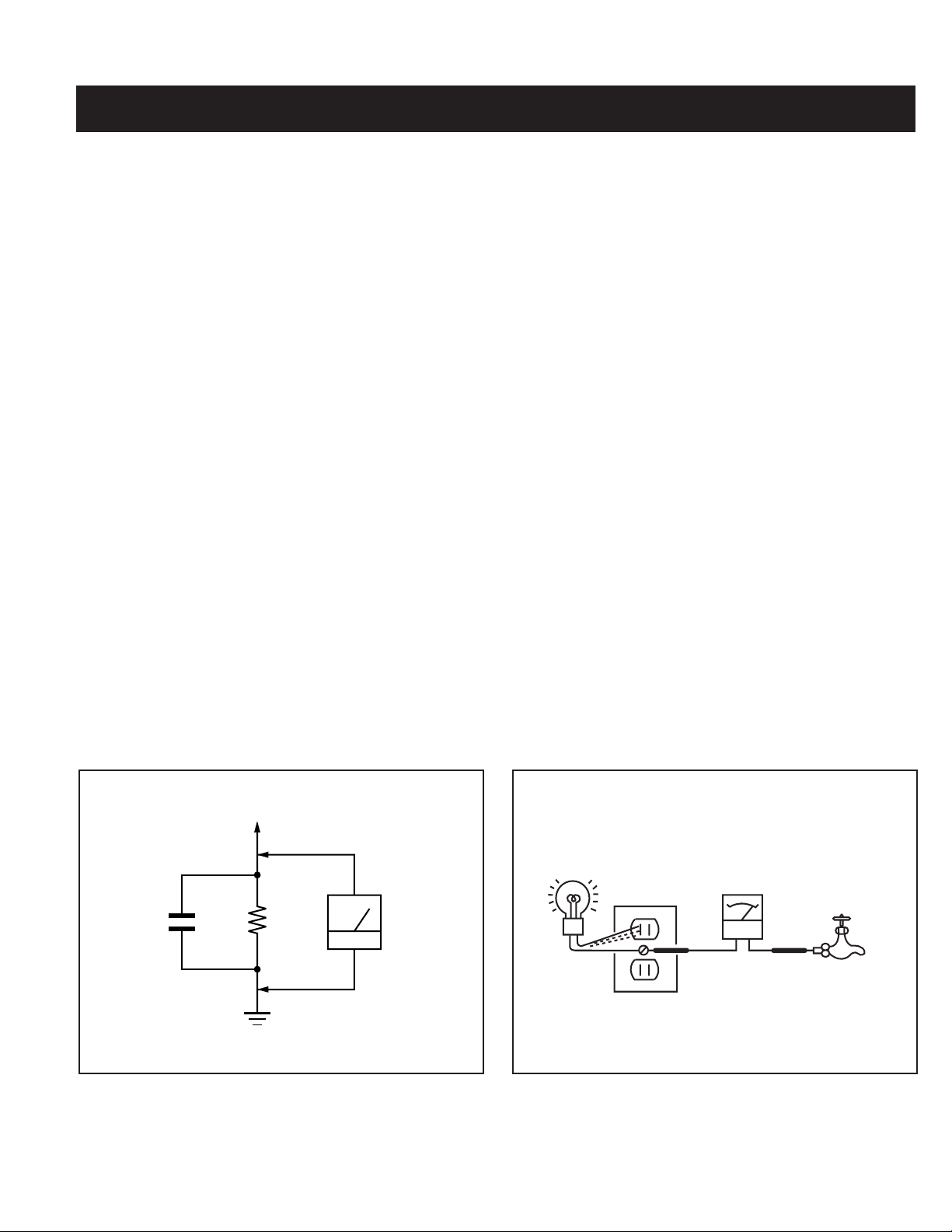
3. Measuring the voltage drop across a resistor by means of a VOM
or battery-operated AC voltmeter. The “limit” indication is 0.75 V,
so analog meters must have an accurate low voltage scale. The
Simpson’s 250 and Sanwa SH-63TRD are examples of passive
VOMs that are suitable. Nearly all battery-operated digital multimeters
that have a 2 VAC range are suitable (see Figure A).
How to Find a Good Earth Ground
A cold-water pipe is a guaranteed earth ground; the cover-plate retaining
screw on most AC outlet boxes is also at earth ground. If the retaining
screw is to be used as your earth ground, verify that it is at ground
by measuring the resistance between it and a cold-water pipe with an
ohmmeter. The reading should be zero ohms.
If a cold-water pipe is not accessible, connect a 60- to 100-watt troublelight (not a neon lamp) between the hot side of the receptacle and the
retaining screw. Try both slots, if necessary, to locate the hot side on the
line; the lamp should light at normal brilliance if the screw is at ground
potential (see Figure B).
To Exposed Metal
Parts on Set
Trouble Light
AC Outlet Box
0.15 F
1.5 K Ω
Earth Ground
Figure A. Using an AC voltmeter to check AC leakage. Figure B. Checking for earth ground.
AC
Voltmeter
(0.75 V)
Ohmmeter
— 6 —
Cold Water Pipe
Page 6
KV-40XBR700
SELF-DIAGNOSTIC FUNCTION
Self Diagnosis
Supported model
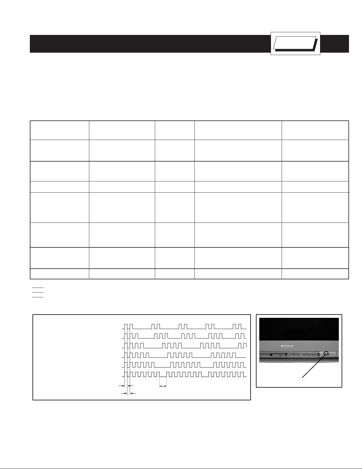
The units in this manual contain a self-diagnostic function. If an error occurs, the STANDBY/STEREO LED will automatically begin to fl ash. The number
of times the LED fl ashes translates to a probable source of the problem. A defi nition of the STANDBY/STEREO LED fl ash indicators is listed in the
instruction manual for the user’s knowledge and reference. If an error symptom cannot be reproduced, the Remote Commander can be used to review
the failure occurrence data stored in memory to reveal past problems and how often these problems occur.
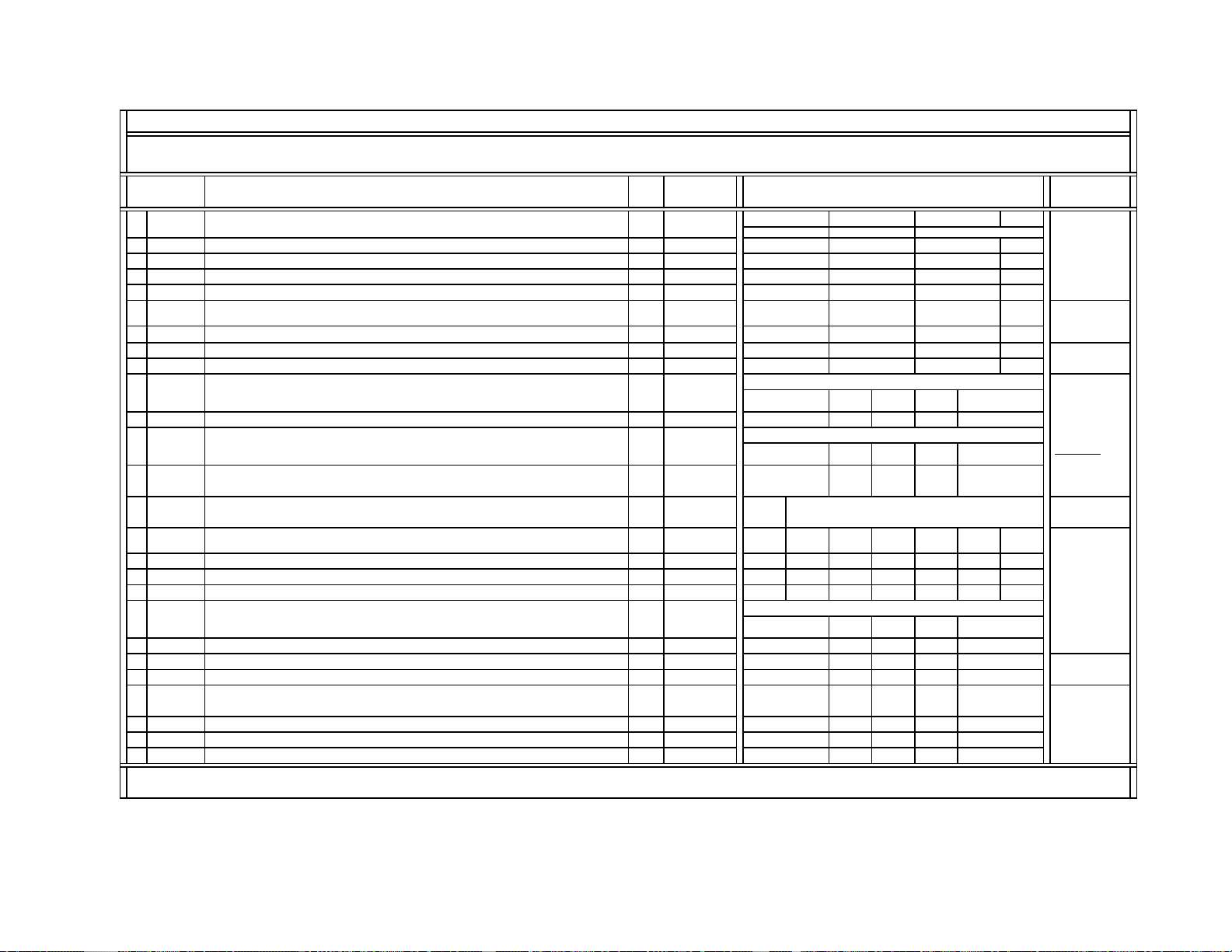
Diagnostic Test Indicators
When an error occurs, the STANDBY/STEREO LED will fl ash a set number of times to indicate the possible cause of the problem. If there is more
than one error, the LED will identify the fi rst of the problem areas.
Results for all of the following diagnostic items are displayed on screen. No error has occurred if the screen displays a “0”.
No. of times STANDBY/
Diagnostic Item STEREO lamp fl ashes Display Result Probable Cause Location Detected Symptoms
Power does not turn on Does not light • Power cord is not plugged in. • Power does not come on.
• Fuse is burned out F6001 (A Board). • No power is supplied to the TV.
• AC power supply is faulty.
+B Overcurrent (OCP) 2 times 2:0 or 2:1 • H.OUT (Q5030) is shorted (D Board). • Power does not come on.
(See Note 1) • +B PWM (Q5003) is shorted (D Board). • Load on power line is shorted.
• IC9001, IC9002, IC9003 is shorted (C Board).
+B Overvoltage (OVP) 3 times 3:0 or 3:1 • IC6505 is faulty (D Board). • Has entered standby mode.
Vertical Defl ection Stopped 4 times 4:0 or 4:1 • ± 15V is not supplied (D Board). • Has entered standby state after
• IC5004 is faulty (D Board). horizontal raster.
• Vertical defl ection pulse is stopped.
• Power line is shorted or power
supply is stopped.
White Balance Failure 5 times 5:0 or 5:1 • Video OUT (IC9001-IC9003) is faulty (C Board). • No raster is generated.
(not balanced) • CRT drive (IC201) is faulty (A Board). • CRT Cathode current detection
• G2 is improperly adjusted (See Note 2). reference pulse output is small.
LOW B OCP/OVP 6 times 6:0 or 6:1 • +5 line is overloaded (A, B Boards). • No picture.
(overcurrent/overvoltage) • +5 line is shorted (A, B Boards).
(See Note 3) • IC6007 is faulty (A Board).
Horizontal Defl ection Stopped 7 times 7:0 or 7:1 • No picture.
Note 1: If a +B Overcurrent is detected, stoppage of the Vertical Defl ection is detected simultaneously. The symptom that is diagnosed fi rst by the microcontroller is displayed on screen.
Note 2: Refer to Screen (G2) Adjustment in Section 2-5. of this manual.
Note 3: If STANDBY/STEREO LED fl ashes six (6) times, unplug the unit and wait 10 seconds before performing the adjustment.
Display of STANDBY/STEREO LED Flash Count
Diagnostic items Flash count
+B Overcurrent (OCP) 2 times
+B Overvoltage (OVP) 3 times
Vert. Deflection Stopped 4 times
White Balance Failure 5 times
Low B OCP/OVP 6 times
Horiz. Deflection Stopped 7 times
Lamp ON 0.3 sec.
Lamp OFF 0.3 sec.
Lamp OFF 3 sec.
STANDBY/STEREO LED
* One fl ash count is not used for self-
diagnostic.
Stopping the STANDBY/STEREO LED Flash
Turn off the power switch on the TV main unit or unplug the power cord from the outlet to stop the STANDBY/STEREO LAMP from fl ashing.
Self-Diagnostic Screen Display
For errors with symptoms such as “power sometimes shuts off” or “screen sometimes goes out” that cannot be confi rmed, it is possible to bring up
past occurrences of failure on the screen for confi rmation.
— 7 —
Page 7
KV-40XBR700
To Bring Up Screen Test
In standby mode, press buttons on the Remote Commander sequentially,
in rapid succession, as shown below:
DISPLAY
Channel 5 Sound volume - Power ON.
SELF DIAGNOSIS
2: +B OCP N/A
3: +B OVP N/A
4: V STOP 0
5: AKB 1
6: LOWB 0
Numeral “0” means that no fault
was detected.
Numeral “1” means a fault was detected
one time only.
7: H-STOP 0
Handling of Self-Diagnostic Screen Display
101: WDT 24
Since the diagnostic results displayed on the screen are not automatically cleared, always check the self-diagnostic screen during repairs. When you
have completed the repairs, clear the result display to “0”.
Unless the result display is cleared to “0”, the self-diagnostic function will not be able to detect subsequent faults after completion of the repairs.
Clearing the Result Display
To clear the result display to “0”, press buttons on the Remote Commander sequentially when the diagnostic screen is displayed, as shown below:
Channel
8
ENTER
Quitting the Self-Diagnostic Screen
To quit the entire self-diagnostic screen, turn off the power switch on the Remote Commander or the main unit.
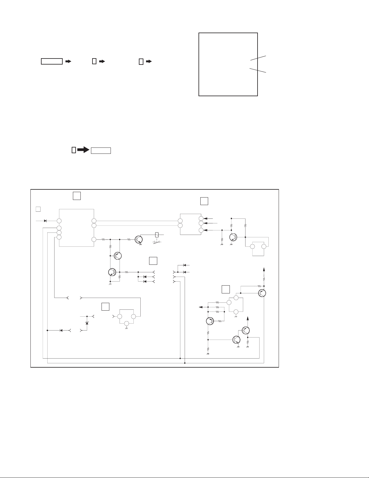
Self-Diagnostic Circuit
HA
STBY LED
STR
48
STBY-LED
OCP
44
45
OVP
43
LOW B ERR
D6018
A
IC701
MAIN UCOM
SET 5V
D6014
OVP
CLKO
DATO
AC RLY
29
30
69
Q6532
A
UNREG 7V
IC6007
I
Q6530
0
Q6527
A
IC201
Y/C JUNGLE
AKB
58
26
SCL
VPROT
25
RY6501
SET ON
D
200V OCP
D6537
D6501
0
OVP
+B OCP
SDA
HPROT
D8027
D8003
+B
Q6520
CRT
35
34
R5125
VDY -
D
1
Q6521
R5104 R5105
Q5018
2
IC6505
+B OVP
3
STBY 5V
Q6524
214
IC5007
I5V
Q6522
+B Overcurrent (OCP)
Occurs when an overcurrent
(more than 6A) on the +B
(135V) line is detected by
R6598/R6591. It will cause
Q6520 to turn on and force the
AC relay to turn off through
Q6532 and Q6530.
+B Overvoltage (OVP)
Occurs when 1) overvoltage
(more than +140V) on the
+B (135V) line is detected by
IC6505, or 2) an overvoltage
(more than 7.5 V) on the unreg
7V line is detected by D6014.
The AC relay will turn off
through Q6532 and Q6530.
Vertical Defl ection Stopped
Occurs when an absence of
the vertical defl ection pulse
is detected by IC201. Power
supply will shut down when
waveform interval exceeds 2
seconds.
White Balance Failure
If the RGB levels* do not balance within 2 seconds after the power is turned on, this error will be detected by IC201. TV will stay on, but there
will be no picture.
*(Refers to the RGB levels of the AKB detection Ref pulse that detects 1K).
Low B OCP/OVP Error
Occurs when set 5V is out.
Horizontal Defl ection Stopped
Occurs when either: 1) a +B overcurrent is detected (IC5007), or 2) overheating is detected (Thermistor TH5002).
— 8 —
Page 8
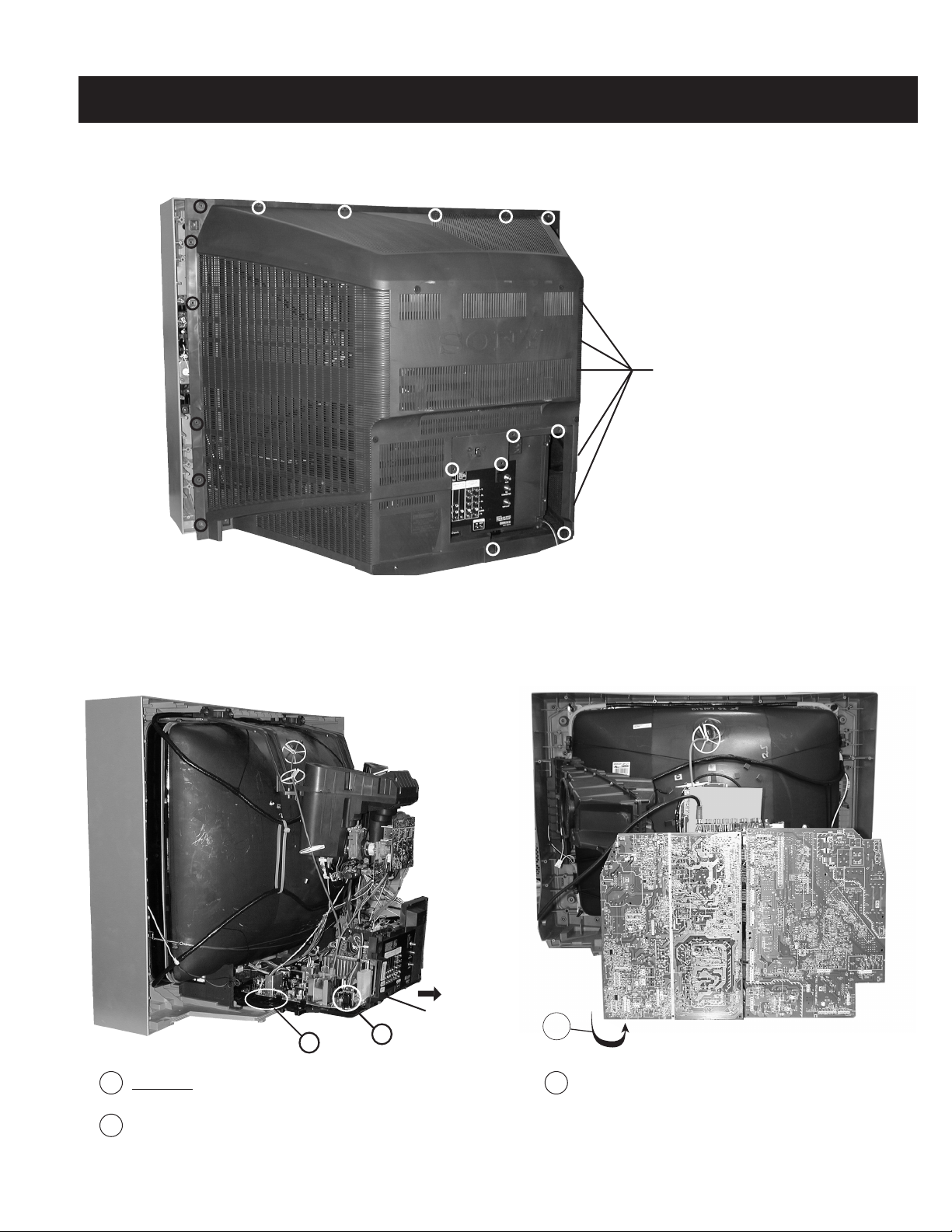
1-1. REAR COVER REMOVAL
KV-40XBR700
SECTION 1: DISASSEMBLY
Remove 22 (+BVTP 4x16) screws from areas
indicated with a circle or line.
1-2. CHASSIS ASSEMBLY REMOVAL 1-3. SERVICE POSITION
2
1
CAUTION! - Heat sink on IC5004 is -15V. Care must be
taken not to allow heat sink to touch any other components.
2
Gently pull the chassis assembly away from the bezel.
1
Chassis
Assembly
1
1
Pull up and rotate both the A and D Boards in order to
service the unit.
— 9 —
Page 9

1-4. PICTURE TUBE REMOVAL
KV-40XBR700
WARNING: BEFORE REMOVING THE ANODE CAP
High voltage remains in the CRT even after the power is disconnected. To avoid electric shock,
discharge CRT before attempting to remove the anode cap. Short between anode and CRT
coated earth ground strap.
Discharge the anode of the CRT and remove the
1
anode cap.
2
Unplug all interconnecting leads from the defl ection
yoke, neck assembly, degaussing coils and CRT
grounding strap.
3
Remove the Speaker Assemblies.
4
Remove the C Board from the CRT.
5
Remove the chassis assembly.
6
Loosen the neck assembly fi xing screw and remove.
7
Loosen the defl ection yoke fi xing screw and remove.
8
Place the set with the CRT face down on a cushion
and remove the degaussing coil holders.
9
Remove the degaussing coils.
10
Remove the CRT grounding strap and spring tension
devices.
11
Unscrew the four CRT fi xing screws [located on each
CRT corner] and remove the CRT [Take care not to
handle the CRT by the neck].
11
10
9
7
8
6
Coated
Earth
Ground
Strap
1
2
3
4
5
ANODE CAP REMOVAL PROCEDURE
WARNING: High voltage remains in the CRT even after the power is disconnected. To avoid electric shock, discharge CRT before attempting to remove
the anode cap. Short between anode and coated earth ground strap of CRT.
NOTE: After removing the anode cap, short circuit the anode of the picture tube and the anode cap to either the metal chassis, CRT shield, or
carbon painted on the CRT.
REMOVAL PROCEDURES
c
b
a
Anode Button
Turn up one side of the rubber cap in
the direction indicated by arrow
a
.
Use your thumb to pull the rubber
cap fi rmly in the direction indicated
by arrow
.
b
When one side of the rubber cap separates from
the anode button, the anode cap can be removed
by turning the rubber cap and pulling it in the
direction of arrow
.
c
HOW TO HANDLE AN ANODE CAP
1. Do not use sharp objects which may cause damage to the surface of the
anode cap.
2. To avoid damaging the anode cap, do not squeeze the rubber covering too hard.
A material fi tting called a shatter-hook terminal is built into the rubber.
3. Do not force turn the foot of the rubber cover. This may cause the shatter-hook
terminal to protrude and damage the rubber.
— 10 —
Page 10

SECTION 2: SET-UP ADJUSTMENTS
KV-40XBR700
The following adjustments should be made when a complete
realignment is required or a new picture tube is installed.
These adjustments should be performed with rated power supply
voltage unless otherwise noted.
The controls and switch should be set as follows unless otherwise
noted:
VIDEO MODE: STANDARD (RESET)
2-1. BEAM LANDING
Preparation:
• Input a white pattern signal.
• Face the picture tube in an East or West direction to reduce the
infl uence of geomagnetism.
NOTE: Do not use the hand degausser; it magnetizes the CRT .
1. Input white pattern from pattern generator. Set the PICTURE control
to maximum, and the BRIGHTNESS control to standard.
2. Perform Focus, G2 and White Balance adjustments.
3. Loosen the defl ection yoke mounting screw, and set the purity control
to the center as shown below:
Purity Control
Perform the adjustments in order as follows:
1. Beam Landing
2. Convergence
3. Focus
4. Screen (G2)
5. White Balance
Test Equipment Required:
1. Color Bar Pattern Generator
2. Degausser
3. DC Power Supply
4. Digital Multimeter
6. Move the defl ection yoke forward, and adjust so that the entire screen
becomes green.
7. Switch over the raster signal to red and blue and confi rm the
condition.
8. When the position of the defl ection yoke is determined, tighten it with
the defl ection yoke mounting screw.
9. If landing at the corner is not right, adjust it by using the disk magnets.
4. Input a green pattern from the pattern generator.
5. Move the defl ection yoke backwards, and adjust with the purity control
so that green is in the center and red and blue are even on both
sides.
Blue Red
Green
— 11 —
Purity control
corrects this area.
Disk magnets
or rotatable disk
magnets correct
thses areas (a-d).
Deflection yoke positioning
corrects these areas.
b
d
a
c
Page 11
KV-40XBR700
2-2. V-PIN AND V-CEN ADJUSTMENT
Preparation:
• Input a cross hatch pattern signal.
• Face the picture tube in a North/South direction and correct rotation.
• Set Video Mode to: Standard (Reset)
1. Adjust service mode CXA2150D-1 04 V-CEN so that the top pin and
bottom pin are symmetrical from top to bottom.
2. Adjust service mode CXA2150D-1 05 V-PIN so that the top pin and
bottom pin are symmetrical from top to bottom.
3. Lines should be straight from left to right. Check landing for side
effect.
2-3. CONVERGENGE
Preparation:
• Set the CONTRAST and BRIGHTNESS control to 50%.
• Input HD dot pattern.
2-3.1. VERTICAL AND HORIZONTAL STATIC
CONVERGENCE
1. Disconnect the dynamic convergence before adjusting static
convergence (CN5510), except for minor touch-up.
2. Adjust H.STAT convergence, RV9001, to converge red, green, and
blue dots in the center of the screen.
3. Adjust V. STAT magnet to converge red, green and blue dots in the
center of the screen.
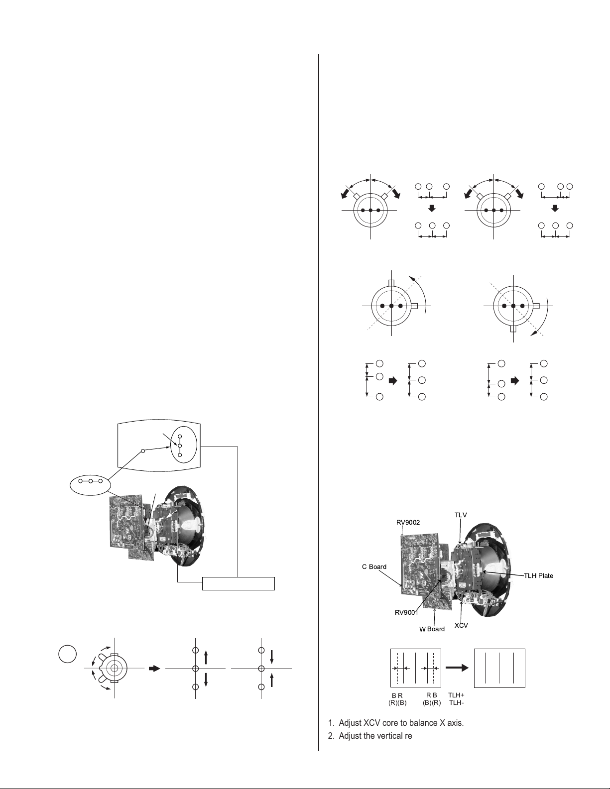
2-3.2. OPERATION OF BMC (HEXAPOLE)
MAGNET
The respective dot positions result from moving each magnet interact.
Perform the following adjustments while tracking.
1. Use the V.STAT tabs to adjust the red, green and blue dots so that
they line up at the center of the screen (move the dots in a horizontal
direction).
HMC Correction HMC Correction
A>B
A=B
R
B
GB
R
AB
RGB
AB
C=D
R
G
B
A=B
VMC Correction
C<D
R
C
G
D
B
A<B
R
AB
RGB
AB
C=D
GB
R
G
B
VMC Correction
C<D
C
G
D
Center dot
R
G
B
RV9001
R G B
V. S TAT
V.STAT magnet
4. Tilt the V.STAT magnet and adjust static convergence to open or close
the V.STAT magnet.
1
B
G
R
B
G
R
2-3.3. TLH PLATE ADJUSTMENT
Preparation:
• Input a cross hatch pattern signal.
• Adjust PICTURE QUALITY to Standard, PICTURE and
BRIGHTNESS to 50%, and OTHER to Standard.
• Adjust unbalanced horizontal convergence of red and blue dots by
adjusting the TLH Plate on the defl ection yoke.
RB
TLV
XCV
TLH+
TLH-
TLH Plate
C Board
RV9002
RV9001
BR
(R)(B)
W Board
(B)(R)
1. Adjust XCV core to balance X axis.
2. Adjust the vertical red and blue convergence with V.TILT (TLV VR).
Note: Perform adjustments while tracking Item 1.
— 12 —
Page 12
KV-40XBR700
NO.
Register
Disp.
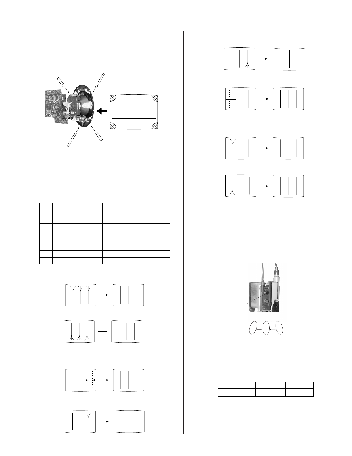
2-3.4. SCREEN-CORNER CONVERGENCE
Preparation:
• Input a cross hatch pattern signal.
1. Affi x a permalloy assembly corresponding to the misconverged areas.
b
d
a
a
a-d: screen-corner
misconvergence
cd
c
b
2-3.5. DYNAMIC CONVERGENCE
ADJUSTMENTS
Set dynamic convergence using the following service mode adjustment
data.
CXA8070AP
Function Data Length Initial Data
1 YBWU VCA9 0-63 31
2 YBWL VCA10 0-63 31
3 RSAP DC-AMP1 0-63 31
4 RUBW VCA5 0-63 31
5 RLBW VCA6 0-63 31
6 LSAP DC-AMP2 0-63 31
7 LUBW VCA10 0-63 31
8 LLBW VCA2 0-63 31
5. RLBW (Right Side Bottom C-BOW)
RB
6. LSAP (Left AMP)
BR
7. LUBW (Left Side Upper C-BOW)
BR
8. LLBW (Left Side Bottom C-BOW)
BR
2-4. FOCUS ADJUSTMENT
1. Input a dot signal.
2. Set Video Mode to STANDARD.
3. Adjust focus VR counter-clockwise to confi rm that the dot’s shape is
centered.
4. Input a HP monoscope signal.
5. Confi rm center focus with focus VR.
1. YBWU (Upper Y-BOW)
BR BR
2. YBWL (Bottom BOW)
BR BR
3. RSAP (Right AMP)
RB
4. RUBW (Right Side Upper C-BOW)
BR
FOCUS
DOT SHAPE:
2-5. SCREEN (G2)
1. Input a monoscope pattern (NTSC).
2. Set to service mode and adjust as follows:
CXA2150P-2
NO.
0 ALBK ALL_BLK 0
3. Adjust RV9002 on the C Board so that the voltage on red, green and
blue cathodes is 175 ± 2 VDC.
4. Adjust the hotizontal line at the top of the screen so it is cut off.
Note: Never set ALBK to 1 when external power supply is connected
to cathode.
— 13 —
Item Avg.
Page 13

KV-40XBR700
2-6. PICTURE QUALITY ADJUSTMENTS
Preparation:
• Set PRO MODE (Picture: MAX, GAMMA: 0).
• Dynamic-color: Off (=Trinitron: MID).
• Set the Service Mode to the following:
C2150P-4
NO. Name Control Function Avg. Data
06 UDCL Dynamic Color: OFF 0
08 UGRAM GRAMMA 5
15 DCTR DC-TRAN 2
16 DPIC DYNAMIC PIC: OFF 1
1. Input signal (480i):
• Color Bar Video 75 IRE (White) 75% modulation 7.5% Set-up.
• Color Bar RF 75 IRE (White) 75% modulation 7.5% Set-up.
2-6.1. VIDEO INPUT - TWO PICTURE SUB
CONTRAST ADJUSTMENT
Preparation:
• Input a Color Bar signal to VIDEO 1 (75 IRE 75%).
• Set picture mode: P&P (PRO MODE).
1. Set to Service Mode and adjust as follows:
2150P-4
NO. Name Control Function Avg. Data
00 UPIC PICTURE 63
02 UCOL COLOR 0
2150P-2
NO. Name Control Function Avg. Data
01 RGBS R ON 4
2103-2
NO. Name Control Function
02 SCON SUB-CONT
white
VR1
black
VR2
GND
VR1-VR2 = VR = 2.08 ± 0.05 Vp-p
5. Write data from Steps 3 and 4 above, into memory.
2-6.2. VIDEO INPUT - SUB HUE/SUB COLOR
ADJUSTMENT
Preparation:
• Input a Color Bar signal to VIDEO 1 (75 IRE 75%).
• Set picture mode: P&P (PRO MODE).
1. Set to Service Mode and adjust as follows:
2150P-4
NO. Name Control Function Avg. Data
00 UPIC PICTURE 63
02 UCOL COLOR 31
2150P-2
NO. Name Control Function Avg. Data
01 RGBS R ON 7
INITIAL DATA (IMPORTANT)
2150P-4
NO. Name Control Function Avg. Data
23 SCON SUB-CONT 8
2103-1
NO. Name Control Function Avg. Data
00 YLEV Y-OUT 23
2103-2
NO. Name Control Function Avg. Data
00 YLEV Y-OUT 23
2. Connect oscilloscope to Pin 1 of CN9001 (R.DRV) on the C Board.
3. Adjust MAIN (left) side contrast according to Service Mode for SCON.
2103-1
NO. Name Control Function
02 SCON SUB-CONT
4. Adjust SUB (right) side contrast according to Service Mode for SCON.
— 14 —
2. Connect an oscilloscope to Pin 5 of CN9001 (B. DRV) on the C Board.
3. Adjust MAIN (left) side color according to Service Mode for SCOL.
4. Adjust MAIN (left) side color according to Service Mode for SHUE.
2103-1
NO. Name Control Function
03 SCOL SUB-COL
04 SHUE SUB-HUE
5. Adjust SUB (right) side color according to Service Mode for SCOL.
6. Adjust SUB (right) side color according to Service Mode for SHUE.
2103-2
NO. Name Control Function
03 SCOL SUB-COL
04 SHUE SUB-HUE
Page 14
T
T
white
Control Function
Avg. Data
Control Function
Avg. Data
Control Function
Avg. Data
KV-40XBR700
VB4
VB3VB2VB1
COLOR: VB1 < VB4 (=VB1 + 0~90 mV)
HUE: VB2 < VB3 (=VB2 + 0~90 mV)
(HUE: Adjust data -2 STEP)
7. Write data into memory.
2-6.3. RF INPUT - TWO PICTURE SUB
CONTRAST ADJUSTMENT
Preparation:
• Input a Color Bar signal to RF (75 IRE 75%).
• Set picture mode: P&P (PRO MODE).
1. Set to Service Mode and adjust as follows:
2150P-4
NO. Name Control Function Avg. Data
00 UPIC PICTURE 63
02 UCOL COLOR 0
2150P-2
NO. Name Control Function Avg. Data
01 RGBS R ON 4
INITIAL DATA (IMPORTANT)
2150P-4
NO. Name Control Function Avg. Data
23 SCON SUB-CONT 9
2103-1
NO. Name Control Function Avg. Data
00 YLEV Y-OU
2103-2
NO. Name Control Function Avg. Data
00 YLEV Y-OU
Note: Use the same average data as 2-6.1., Items 3 - 4 after the
adjustment.
2. Connect an oscilloscope to Pin 1 of CN9001 (R. DRV) on the C
Board.
3. Adjust MAIN (left) side contrast according to service mode for SCON.
2103-1
NO. Name Control Function
02 SCON SUB-CONT
4. Adjust SUB (right) side contrast according to Service Mode for SCON.
2103-2
NO. Name Control Function
02 SCON SUB-CONT
23
23
VR1
black
VR2
GND
VR1-VR2 = VR = 2.08 ± 0.05 Vp-p
5. Write data from Steps 3 - 4 above, into memory.
2-6.4. RF INPUT - SUB HUE/SUB COLOR
ADJUSTMENT
Preparation:
• Input a Color Bar signal to RF (75 IRE 75%).
• Set picture mode: P&P (PRO MODE).
1. Set to Service Mode and adjust as follows:
2150P-4
NO. Name Control Function Avg. Data
00 UPIC PICTURE 63
02 UCOL COLOR 31
2150P-4
NO. Name Control Function Avg. Data
01 RGBS R ON 7
INITIAL DATA (IMPORTANT)
2150P-4
NO. Name
24 CLOF OFFSET for UCOL 8
25 HUOF OFFSET for UHUE 4
2103-1
NO. Name
01 CLEV CB & CR-OUT 20
20 CBOF CB-OFFSET 31
21 CROF CR-OFFSET 31
2103-2
NO. Name
01 CLEV CB & CR-OUT 19
20 CBOF CB-OFFSET 31
21 CROF CR-OFFSET 31
Note: Use the same average data as 2-6.2., Items 3-6 after the
adjustment.
2. Connect an oscilloscope to pin 5 of CN9001 (B. DRV) on the C Board.
3. Adjust MAIN (left) side color according to Service Mode for SCOL.
4. Adjust MAIN (left) side color according to Service Mode for SHUE.
2103-1
NO. Name Control Function
03 SCOL SUB COLOR
04 SHUE SUB HUE
5. Adjust SUB (right) side color according to Service Mode for SCOL.
— 15 —
Page 15
KV-40XBR700
2150P-1
T
NO.
NO.
NO.
6. Adjust SUB (right) side color according to Service Mode for SHUE.
2103-2
NO. Name Control Function
03 SCOL SUB COLOR
04 SHUE SUB HUE
VB4
VB3VB2VB1
COLOR: VB1 < VB4 (=VB1 + 0~90 mV)
HUE: VB2 < VB3 (=VB2 + 0~90 mV)
(HUE: Adjust data -2 STEP)
7. Write data into memory.
2-7. WHITE BALANCE (CRT) AND SUB
BRIGHT ADJUSTMENT
Preparation
• Input an all white 480I (15.734 KHz) signal into the VIDEO 1 input
terminal to perform the White Balance (highlight, cut-off) adjustments.
The parameters to adjust are in the CXA2150P in Service Mode.
1. Set the following:
Picture: Full Mode
Pro Mode
Color: Center
2. Adjust White Balance in the Service Mode and set the following data:
NO. Name Control Function Avg. Data
05 RDRV R-DRIVE Fix: 46
06 GDRV G-DRIVE Adjust
07 BDRV B-DRIVE Adjust
08 RCUT R-CUT OFF Fix: 41
09 GCUT G-CUT OFF Adjust
10 BCUT B-CUT OFF Adjust
2-8. RASTER CENTER ADJUSTMENT
Preparation:
• Input a monoscope signal.
• Set to NTSC (DRC) mode.
1. Set to Service Mode and adjust as follows:
CXA2150P-2
Name Control Function Avg. Data
06 AGNG AGING 1, AGING 2 2
CXA2150D-2
Name Control Function Avg. Data
02 HSIZ Horiz Size 45
CXA2150D-3
Name Control Function Avg. Data
00 HBLK Blanking Enable 0
2. Reduce HSIZ to see sides of raster.
3. Adjust H-Center with CXA2150D-2 00.
4. Adjust to the best screen position with H-CENT and write data.
5. Restore aging, HSIZ and HBLK to original condition.
2-9. PICTURE DISTORTION ADJUSTMENTS
2-9.1. NTSC (DRC) FULL MODE
ADJUSTMENT
1. Face the picture tube in an east-west direction.
2. Complete V-PIN and V-CEN adjsuments fi rst (A2150-D1 05 V-PIN,
A2150-D1 04 V-CEN).
3. Input a monoscope and crosshatch signal. Adjust the picture
distortion with the following service parameters to balance the best
condition for these two signals.
A2150-D1 00 VPOS
A2150-D1 01 VSIZ
A2150-D1 02 VLIN
A2150-D1 03 VSCO
A2150-D1 04 VCEN
A2150-D1 05 VPIN
A2150-D1 07 HTPZ
3. Adjust Sub Brightness: Input an all black signal (to IRE 7.5% set up)
480i (15.75 KHz) signal into the VIDEO 1 input terminal. Adjust the
following parameter of CXA2150P-1:
4. Check Initial Data (Important).
CXA2150P-1
NO. Name Control Function Avg. Data
04 SBRT SUB-BRIGHT 20
2150P-1
NO. Name Control Function Avg. Data
00 SBOT SUB-BRT OFFSET 7
12 SBOF SUB-BRT OFFSE
5. Repeat Steps 2-4.
63
— 16 —
A2150-D2 01 HPOS
A2150-D2 02 HSIZ
A2150-D2 03 SLIN
A2150-D2 04 MPIN
A2150-D2 06 UCP
A2150-D2 07 LCP
A2150-D2 13 PPHA
A2150-D2 14 VANG
A2150-D2 15 LANG
A2150-D2 16 VBOW
A2150-D2 17 LBOW
Note: Make sure that the picture size is within specs. Vertical size is
11.7 ± 0.1 sq. and horizontal size is 15.6 ± 0.1 sq.
4. Write data into memory and then set the screen to 1080i mode.
Page 16

KV-40XBR700
A
CXA2150D-1
0. VPOS (V-POSITION)
1. VSIZ (V-SIZE)
2. VLIN (V-LINE)
3. VSCO (VS-COR)
7. HTPZ (H-TRAPEZOID)
CXA2150D-2
1. HPOS (H-POSITION)
15. LANG (L-ANGLE)
16. VBOW (AFC-BOW)
17. LBOW (L-BOW)
2-9.2. 1080i HD MODE ADJUSTMENT
1. Input a 1080i cross-hatch signal and an HD monoscope signal that
contains overscan markers.
2. Adjust the raster position per Section 2-8., only if this procedure was
not performed for full mode.
3. Adjust the geometry similar to Full DRC mode. Vertical size is 11.7
± 0.1 sq. and horizontal size is 15.6 ± 0.1 sq., if monoscope signal is
available. Otherwise, set the Vertical size to 91.0 ± 0.6% scan and
Horizontal size as 91.0 ± 0.6% scan.
4. Use the following register to adjust the horizontal parameter:
2150-D2 01 HPOS
Note: If necessary, touch up the geometry using the data register
listed above for Full mode.
5. Write the data into memory.
2. HSIZ (H-SIZE)
5. PIN (PIN AMP)
6. UCP (UP COR PIN COR)
7. LCP (LOW CO PIN COR)
13. PPHA (PIN PHASE)
14. VANG (AFC-ANGLE)
2-9.3. VERTICAL COMPRESSED MODE
CHECK AND CONFIRMATION
1. Input a monoscope and crosshatch signal.
2. Check vertical compressed mode.
— 17 —
Page 17
SECTION 3: SAFETY RELATED ADJUSTMENTS
3-1. X RV8001, RV8002 CONFIRMATION METHOD AND HV SERVICE ADJUSTMENTS
KV-40XBR700
3-2. B+ MAX CONFIRMATION
Standard............................................................................ 135.3 ± 1 VDC
Check Condition:
AC input voltage: 120 (± 2) VAC at Board Adjustment Process
130 (± 2) VAC at QC
120 (± 2) VAC at Overall Adjustment (after aging)
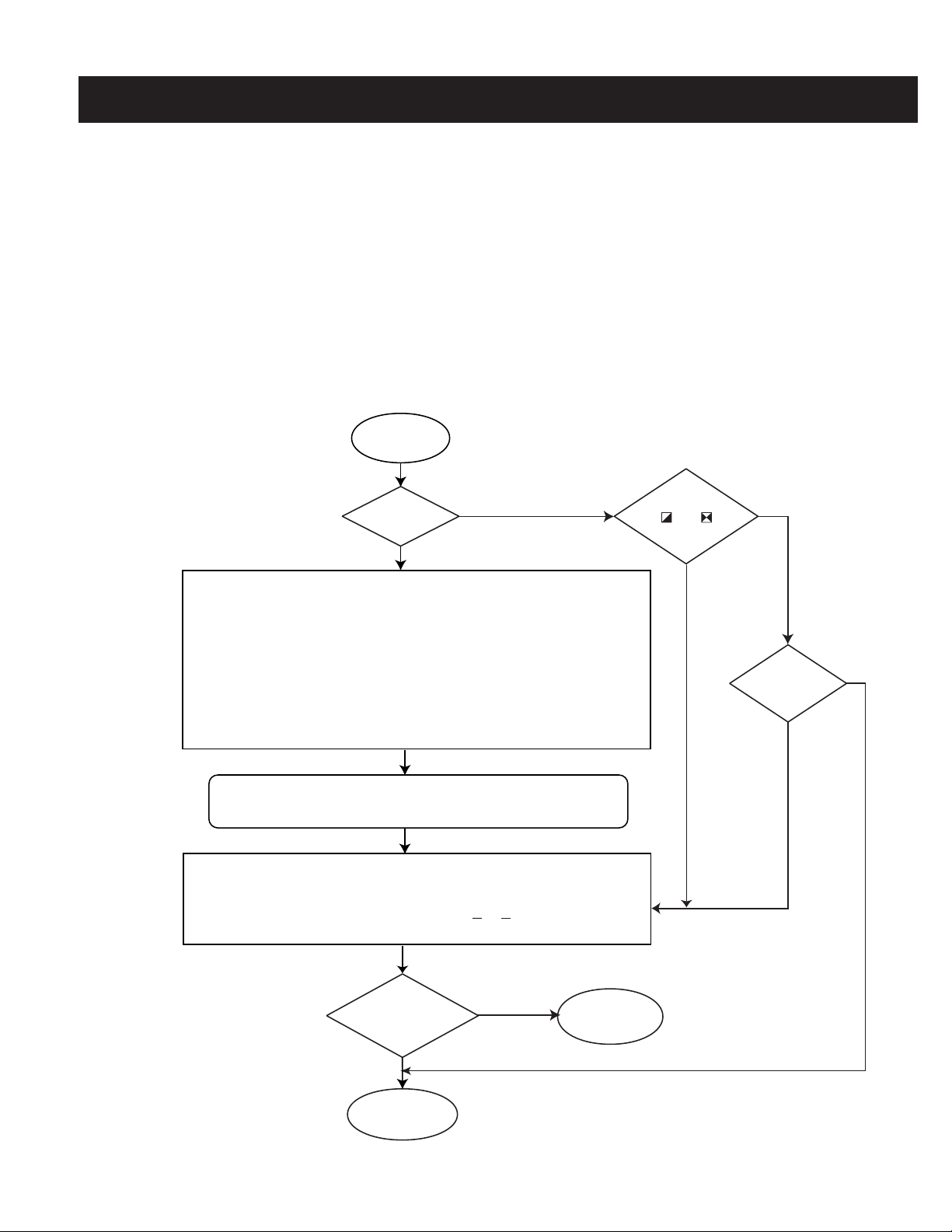
3-3. HV SERVICE FLOWCHART
Start
Is T8001
Changed?
Ye s
Replace RV8001, RV8002 with the same value:
HV project adjust and inspection
1. Turn RV8001 fully counter-clockwise.
2. Turn set on with black video signal then adjust RV8002 slowly to obtain
35.5kV.
3. Turn RV8001 clockwise slowly until hold down operation initially activates.
4. Adjust RV8002 clockwise, then turn the set on. Change video to white field then
slowly turn RV8002 counter-clockwise to get 34.8 ± 0.2kV. Confirm set does
NOT TURN OFF at this condition. If yes, then repeat from step 1 again.
5. Finally, set back RV8002 to 31.50kv + 0.2kv at video cut off (black video).
No
Note: If using a stabilized power supply, make sure that the distortion
factor is 3% or less.
Setting Mode:........................................................................... Full mode
Signal Input:................................................ Cross-hatch of NTSC at QC
Initial Setting:........................................................ Reset condition at QC
Confi rm Point:.......................................Across C6544 for B+ of D Board
Change any
or
marked parts
Ye s
No
Is D-Board
Replaced?
Ye s
No
If all adjustments are complete, then seal and secure RV8001, RV8002 with
epoxy to prevent any possible misadjustment by non-trained technical
Confirm +B, Vd and check hold-down on the D Board video with no signal (standard
reset mode) as follows:
1. Confirm +B across C6544 to make sure that it is 135.3 ± 1 Vdc.
2. Confirm Vd at Pin 2 CN5506 or at TP-Vd for 4.3V < Vd < 4.65 Vdc.
3. Apply 5.5 ± 0.5 Vdc at Pin 2 of CN5506, then confirm that set holds down.
service.
Is +B, Vd and
hold down
confirmed?
Ye s
Finish for
hold-down
check.
Start from
the beginning.
— 18 —
Page 18

SECTION 4: CIRCUIT ADJUSTMENTS
Y
ELECTRICAL ADJUSTMENTS BY REMOTE COMMANDER
Use the Remote Commander (RM-Y184) to perform the circuit adjustments in this section.
Test Equipment Required: 1. Pattern generator 2. Frequency counter 3. Digital multimeter 4. Audio oscillator
KV-40XBR700
4-1. SETTING THE SERVICE ADJUSTMENT
MODE
1. Standby mode (Power off).
2. Press the following buttons on the Remote Commander within one
second of each other:
DISPLAY
Channel 5 Sound Volume
+
Power
SERVICE ADJUSTMENT MODE VIEW
Device Item Data Item
Register
Item
2150P-1 0 +7 SERVICE
SBOT TV
WSL: 0
F/A FLAG:
CBA FLAG:
READING THE MEMORY
1. Enter into Service Mode.
2. Press 0 on the Remote Commander.
3. Press
ENTER
to read memory.
ADJUSTING THE PICTURE
1. Enter into Service Mode
2. Press 2 or 5 on the remote to select the device item.
3. Press
4. Press
5. Press
1
or 4 on the remote to select an item.
or 6 on the remote to change the data.
3
ENTER
MUTING
then
to write into memory.
4-1.1. RESETTING THE DATA
4-2. MEMORY WRITE CONFIRMATION
METHOD
1. After adjustment, pull out the plug from the AC outlet, then replace the
plug in the AC outlet again.
2. Turn the power switch ON and set to Service Mode.
3. Call the adjusted items again to confi rm they were adjusted.
4-3. REMOTE ADJUSTMENT BUTTONS AND
INDICATORS
WRITE
INTO MEMORY
ITEM UP
ITEM DOWN
TEST
RESET
DEVICE UP
DATA UP
DATA DOWN
DEVICE DOWN
EXECUTE
READ
MEMOR
Note: Be careful when using the remote! It will clear and re-initialize
ALL NVM data including defl ection adjustment data if not reset
properly as follows:
RESETTING THE DEFLECTION NVM DATA
1. Enter into Service Mode.
2. Press 7, then
MENU
, and then press
ENTER
on the remote.
RESETTING THE SYSTEM NVM DATA
1. Enter into Service Mode.
2. Press
7
, then 9, and then press
ENTER
on the remote.
RESETTING THE SYSTEM NVM DATA
1. Enter into Service Mode.
2. Press 8 and then press
ENTER
on the remote.
— 19 —
RM-Y184
Page 19
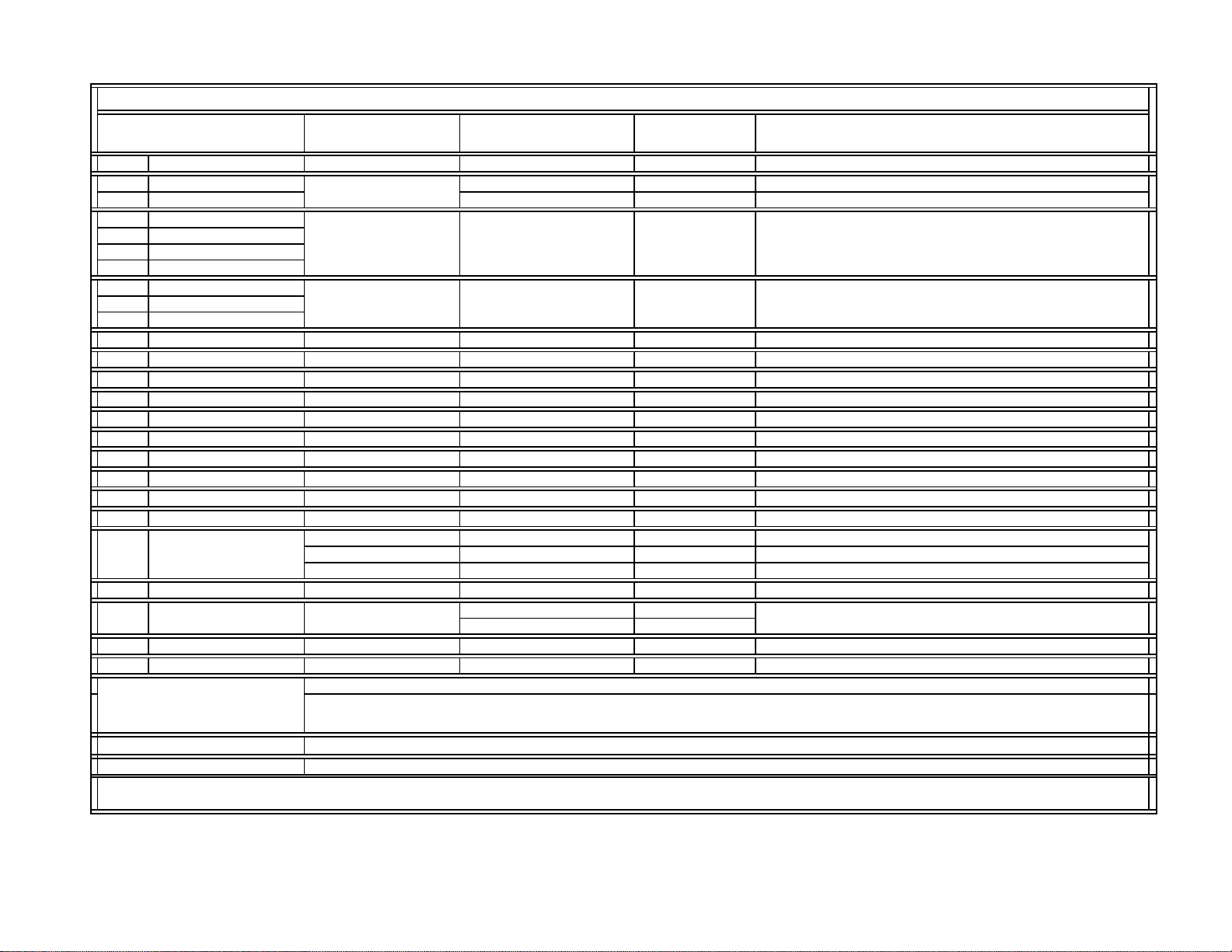
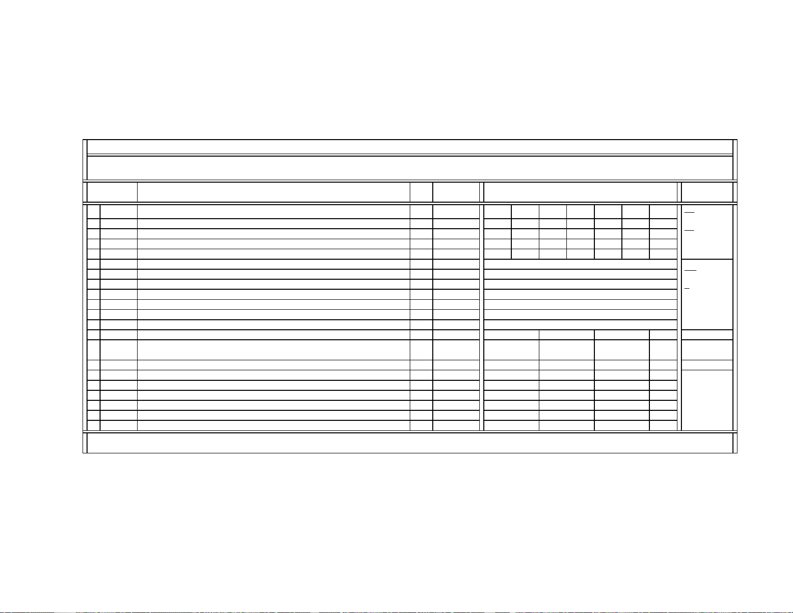
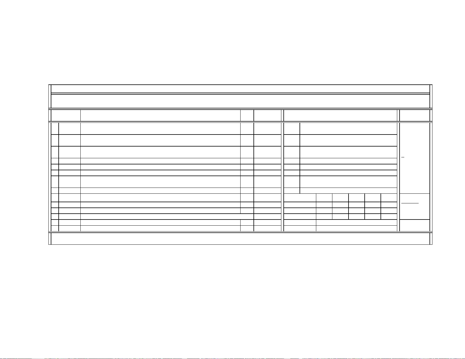
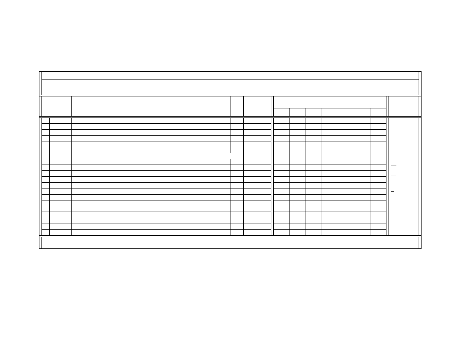
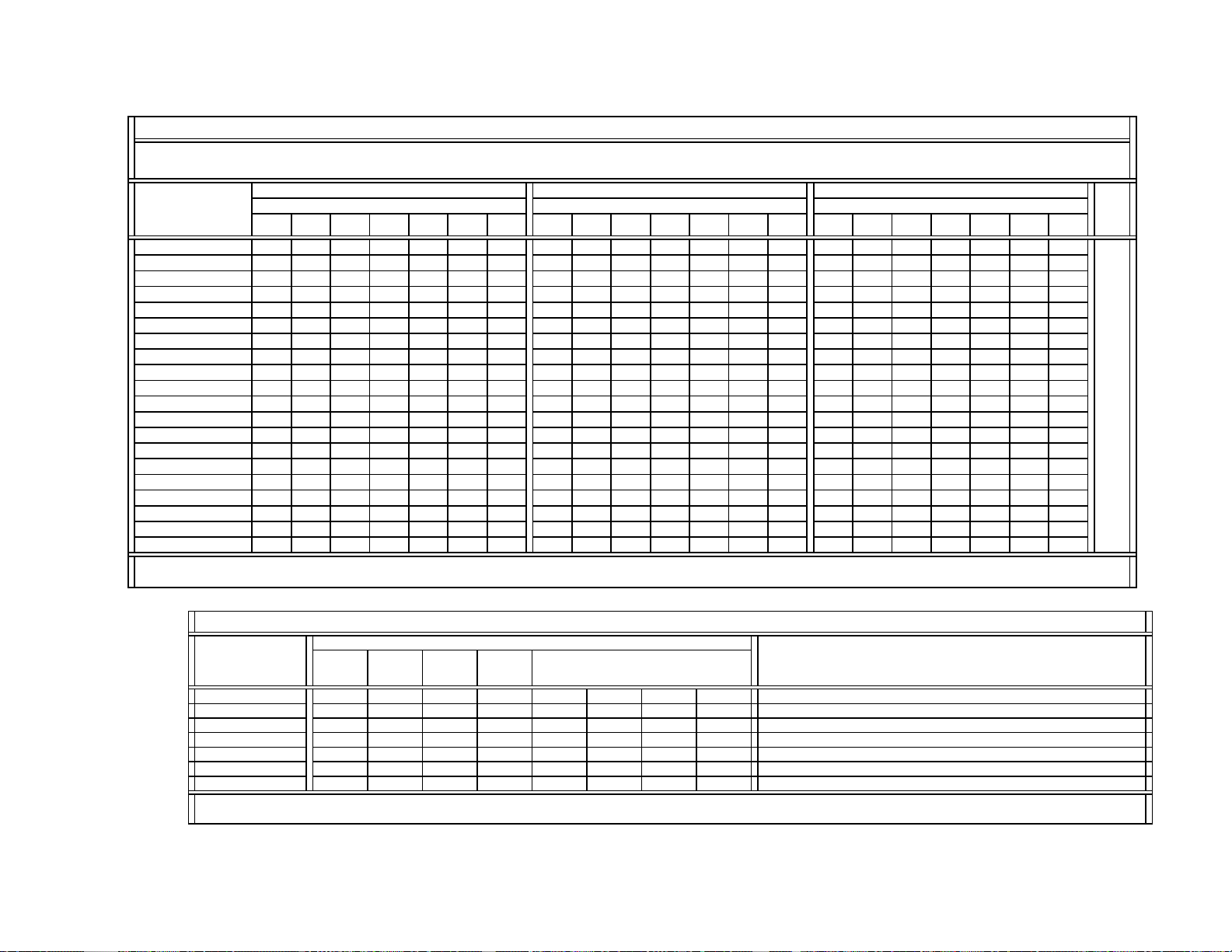
4-4. SERVICE DATA LISTS
V
BH3868FS
Controlled through CXA1315M ( IC4103 / S-board / 48h )
Controlled through MID-XA Micro ( IC3090 / B-board / 64h )
Controlled through MID-XA Micro ( IC3090 / B-board / 64h )
Controlled through MID-XA Micro ( IC3090 / B-board / 64h )
Controlled through MID-XA Micro ( IC3090 / B-board / 64h )
}
68h (Main)
6Ch (Sub)
}
}
s
DX1A-2001* Service List ------ Contents & Notes
Category Number & Name
# 1 3D-COMB µPD64082 IC3501 / BC-board B8h (W) & B9h (R) W&R: Write & Read
# 2-1 CXA2103-1 (Main) IC3048 (Main) / B-board 9Ah
# 2-2 CXA2103-2 (Sub) IC3110 (Sub) / B-board 9Eh
# 3-1 CXA2150P-1
# 3-2 CXA2150P-2
# 3-3 CXA2150P-3
# 3-4 CXA2150P-4
# 4-1 CXA2150D-1
# 4-2 CXA2150D-2
# 4-3 CXA2150D-3
# 5 CXA2151 CXA2151Q IC3001 / B-board 84h
# 6 D-CON
# 7 CXA2026 CXA2026AS IC5511 / D-board 8Eh
# 8 AP
# 9 TRUS NJM2180M IC4101 / S-board 2Eh
# 10 MID1 CXD9509AQ IC3408 / B-board 2Eh
# 11 MID2 CXD9509AQ IC3408 / B-board 2Eh
# 12 MID3 CXD9509AQ IC3408 / B-board 2Eh
# 13 MID5 CXD9509AQ IC3408 / B-board 2Eh
# 14
# 15
# 16 ID1 CXD2085M IC3603 / B-board 40h
# 17
# 18
# 19
DX1A-2001 System Micro &
Notes for Services
DX1A-2001 MID-XA Micro
DX1A-2001 CCD&Vchip Micro
Note:
* This service list is used for DX1A-2001 ONLY. Some service data is the same in DX1A-2001 & 2000, as noted in the data sheets.
OSD
SNNR
CCD&VCHIP
OP
ID
Device Name
CXA2103Q
CXA2150Q 86h
CXA8070P IC5513 / D-board DEh
M306V2ME-153FP IC701 / A-board 60h DX1A-2001 System Micro {V1.0
µPD64082 IC3501 / BC-board B8h (W) & B9h (R)
CXA2103Q IC3048 (Main) / B-board 9Ah
CXA2150Q IC201 / A-board 86h
CXP85840A-039Q
M306V2ME-153FP IC701 / A-board 60h DX1A-2001 System Micro {V1.0
M306V2ME-153FP IC701 / A-board 60h DX1A-2001 System Micro {V1.0
M306V2ME-153FP (MASK), Software Version 1.0, IC701/A-board (Slave Adress: 60h)
The system micro name, software&patch versions, and the status of NVM devices are displayed only when in the service catergory
(#19): ID.
MB94918RPF-G-137-BND (MASK), Software Version 12/08/00, IC3090/B-board (Slave Address: 64h)
CXP85840A-039Q (MASK), Software Version 2.14, IC3602/B-board (Main/Slave Address: 68h) & IC3601/B-board (Sub/Slave Address:
Device Reference
Number
IC201 / A-board
IC201 / A-board
IC7001 / A-board 82h
IC3602 (Main) / B-board
IC3601 (Sub) / B-board
Slave Address Comment
86hCXA2150Q
CCD&Vchip Micro (V2.14)
KV-40XBR700
— 20 —
Page 20
SERVICE DATA LISTS
Non-standard
g
(
g)
y
g
Non-standard
NSDS
g
p
g
p
(
p)
g)
A
g
g)
A
Y
(
)
(
)
(
)
p
Y
p
y
Y
p
)
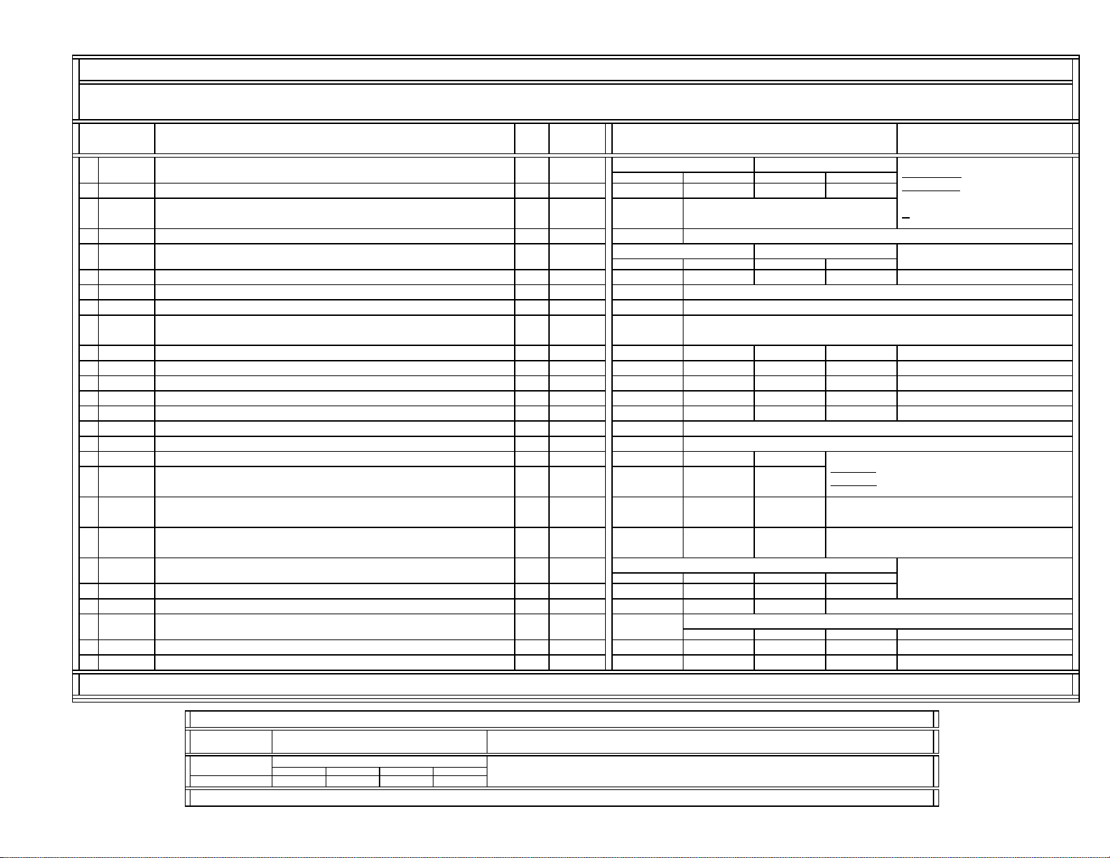
DX1A-2001&2000 SERVICE LIST (#1): 3D-COMB / mPD64082 (Part-1/4)
Device Name: mPD64082GF { 3D-Comb Filter / NEC } / IC3501 (BC-board) / P/N: 8-759-594-44 (SB#: V7372)
Slave Address: B8h (Write Address) / B9h (Read Address)
Register
No & Name
0
NRMD
1
YAPS
2
CLKS
3
4
MSS
5
KILS
6
CDL
7
DYCO
8
DYG
9
DCCO
10
DCG
11
12
CNRL
13
VTRH
14
VTRR
15
LDSR
16
VAPG
17
VAPI
18
19
Note: The same 3D-COMB service data is used for DX1A-2001&2000.
Operation mode settin
Y-output correction
V-aperture compensation & Y-peaking filterin
S
stem clock settin
Selection for standard/non-standard signal processin
Selection for inter-frame/inter-line
Killer
rocessing selection C 0~3 1
C-signal phase with respect to the Y-signal
Fine adjustment at 70 ns/ste
NRMD Setting-based Control Table for DYCO, DYGA, DCCO, DCGA NRMD = 0 NRMD = 1 NRMD = 2 NRMD = 3
DY detection coring level (Y motion detection corin
DY detection gain (Y motion detection gain) 0~15 10 10 10 10
DC detection corin
DC detection gain (C motion detection gain) 0~15 5555
Frame recersive YNR nonlinear filter limit level C 0~3 1
NRL
Frame recersive CNR nonlinear filter limit level C 0~3 1
Hysteresis for Hsync non-standard signal detection
out-of-Hsync intra-field
Sensitivity for Hsync non-standard signal detection
out-of-Hsync intra-field
Sensitivity for frame non-standard signal detection
out-of-Hsync inter-frame
VM&SNNR Setting-based Control Table for VAPG & VAPI
VAPG= VAPG1 - VAPG2
V-aperture compensation gain 0~70234
V-a
erture compensation convergence point 0~31 4 4 4
SNNR Setting-based Control Table for YPFT & YHFG
Y
PFT
PFG
eaking filter (BPF) center frequenc
Y
eaking filter (BPF) gain 0~15 7012 3
Control Register
Function & Link
rocessin
level (C motion detection corin
Data
Type
Data
Range
0~30133
C 0~3 3
C 0~3 1
0~30000
C 0~3 0
C 0~7 3
0~15 2222
0~15 5555
0~3 1 1 1
0~3 1 1 1
0~3 2 2 2
0~30000 0
Data Initial/Average Setting
(32V&36V CRTs)
Standard
Standard
UHF/VHF Video1~4 Video5&6
VAPG1 Data Based on MENU/VM Setting
VM = Off VM = Low VM = Mid VM = High
SNNR = 0 SNNR = 1 SNNR = 2 SNNR = 3
SVideoUHF/VHF & CVideo
Standard Non-standard
SVideoUHF/VHF & CVideo
Standard Non-standard
Video1~4
Video5&6
SNNR Setting (-Offset)
: CVideo1~4 & SVideo1~3 inputs
: YPbPr-480i/480p/1080i inputs
KV-40XBR700
Comment
CVideo (CV): CVideo1~4 inputs
SVideo (SV)
: Common data
C
: SVideo1~3 inputs
This setting continues to
the next page.
8
DX1A-2001&2000 SERVICE LIST (#1): 3D-COMB / mPD64082 (Part-2/4)
Register
No & Name
#16 VAPG (cont.
Note: The same 3D-COMB service data is used for DX1A-2001&2000.
Data Initial/Average Setting
(32V&36V CRTs)
VAPG2 Data Based on SNNR/Offset-setting
SNNR = 0 SNNR = 1 SNNR = 2 SNNR = 3
0000
Comment
— 21 —
Page 21
SERVICE DATA LISTS
a
yp
(
)
(ms)}
{
)}
g
y
)
KV-40XBR700
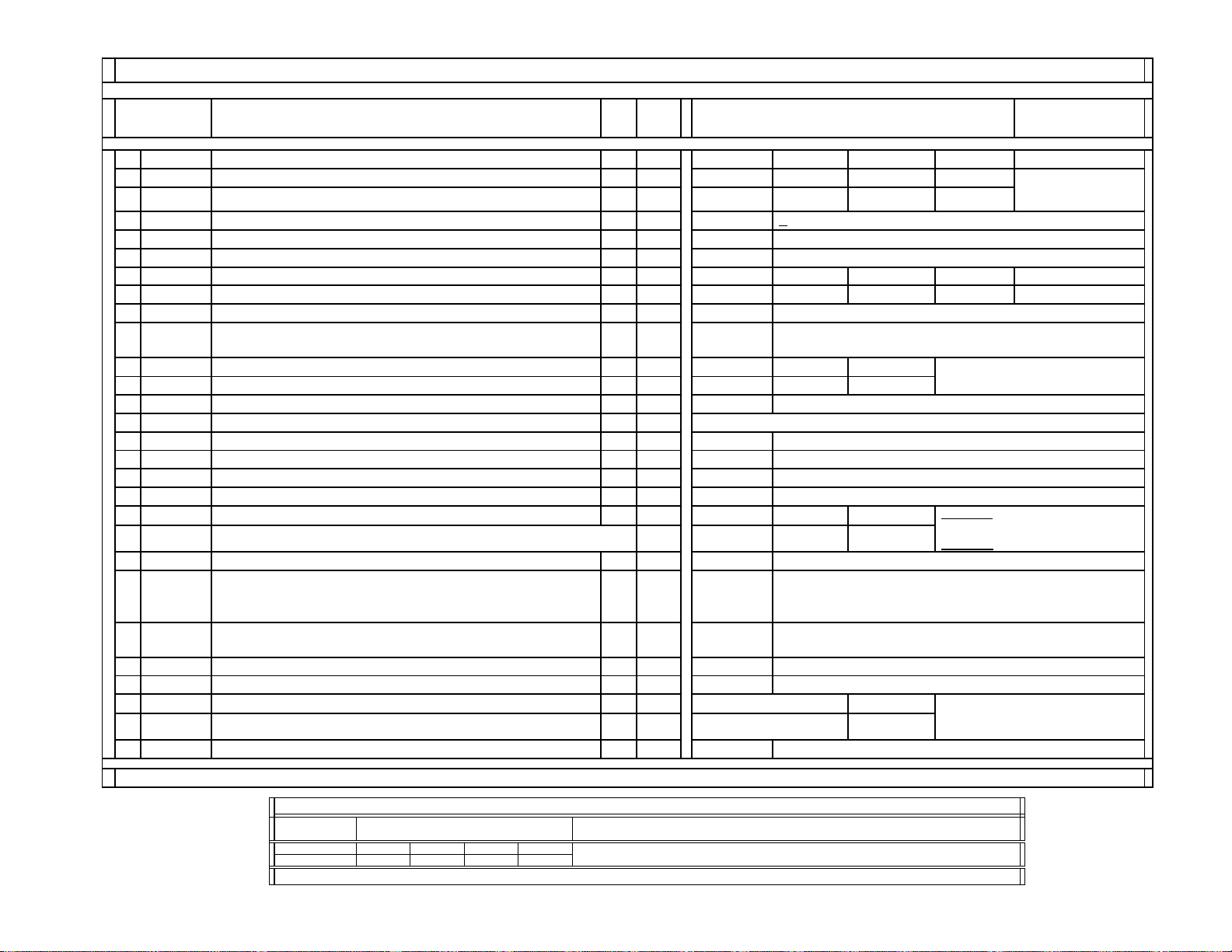
DX1A-2001&2000 SERVICE LIST (#1): 3D-COMB / mPD64082 (Part-3/4)
Register
No. & Name
20
YHCO
21
YHCG
22
HSSL
23
VSSL
24
ADCL
25
D2GA
26
KILR
27
OP1
28
NR1
29
NR2
30
WSL
31
HPLL H-PLL filter
32
BPLL
33
FSCF
34
PLLF
35
CC3N
36
HDP
37
BGPS
38
BGPW
39
TEST
40
WSC
41
LIND
42
PFGO
Control Register
Function & Link
SNNR Setting-based Control Table for YHCO & YHCG SNNR = 0 SNNR = 1 SNNR = 2 SNNR = 3
Data
Type
Data
Range
Data Initial/Average Setting
(32V&36V CRTs)
Y output high frequency component coring 0~3 1 1 1 1
Y output high frequency component coring gain 0, 1 0 0 0 0
Hsync slice level C 0~15 12
C: Common data
Vsync slice level C 0~15 8
ADC clock delay C 0~3 3
NRMD Setting-based Control Table for D2GA NRMD = 0 NRMD = 1 NRMD = 2 NRMD = 3
Moving detection gain 0~7 4 4 4 4
Killer detection reference C 0~15 3
Option1:
Selection of comb filter & recursive noise reduction t
C 0, 1 1
es
UHF/VHF CVideo1 SVideo1
This setting continues to
Noise reduction on/off 0, 1 0 0 1
SNNR control on/off C 0, 1 0
Noise level detection data 0~255
Must be set to 1 when MN signal is input.
Burst PLL filter
Burst extraction gain
PLL loop gain
0, 1 1
C
0, 1 1
C
0, 1 0
C
0, 1 1
C
Selection of a line-comb filter C separation filter characteristic 0, 1 0 0 0
1 Byte Data from Read Register WSL
UHF/VHF Video1~4 Video5&6
Video1~4
inputs
Video5&6
Fine adjustment of the system H-phase C 0~7 5
Internal burst gate start position
{Gate Start Position from Hsync center = 0.25 x BGPS +
C 0~15 4
2
Internal burst gate width
Gate Width = 0.25 x BGPW + 0.5 (ms
Test bit {0: Normal mode, 1: Test mode (forbidden settin
C 0~15 10
C 0, 1 0
Amount of noise detection coring C 0~3 1
UHF/VHF & Video1~4
DRC-M line-doubling setting for non-standard signals
Micro
0~63 2
(YPFG offset at GR on) --- Not used for DX1A --- 0~7 3
Video5&6
0
(Not used for DX1A)
This setting is used for non-standard
signals
such as Play Station signals.
Comment
(Not SNNR Offset Dat
YHCO&YHCG
settings are sent
to 3D-Comb
directl
the next page.
: CVideo1~4 & SVideo1~3
: YPbPr-480i/480p/1080i
Note: The same 3D-COMB service data is used for DX1A-2001&2000.
Register
No & Name
#28 NR1 (cont.
Note: The same 3D-COMB service data is used for DX1A-2001&2000.
CVideo2 SVideo2 CVideo3 SVideo3
0101
DX1A-2001&2000 SERVICE LIST (#1): 3D-COMB / mPD64082 (Part-4/4)
Data Initial/Average Setting
(32V&36V CRTs)
Comment
— 22 —
Page 22

SERVICE DATA LISTS
Y
g
YDLY
Y
(
)
(
)
(-offset)
(
)
g
g
Y
p
)
y
SSMD
g
A
7 [Adj.-2steps]
KV-40XBR700
DX1A-2001&2000 SERVICE LIST (#2-1):
CXA2103-1 {Main}
Device Name: CXA2103Q { NTSC-YCT (Chroma Decoder) / SONY } / IC3048 (B-board) / P/N: 8-752-089-50 (SBorSD#: NA)
Slave Address: 9Ah { Main }
Register
No & Name
0
1
CLEV
2
SCON
3
SCOL
4
SHUE
5
6
SHAP
7
SHF0
8
PREO
9
BPF0
10
BPFQ
11
BPSW
12
TRAP
13
14
AFCG AFC Loo
15
CDMD
16
17
HMSK
18
HALI
19
PPH
20
CBOF
21
CROF
22
ATPD
23
DCTR
Note: The same CXA2103 service data (Main&Sub) is used for DX1A-2001&2000.
Y-Out
LEV
Cb&Cr-Out gains 0~63 20 55* 37 31*
Sub contrast
Sub color
Sub hue Adj. 0~15
Y/C delay time 0~3
SNNR Data-related Settings UHF/VHF CVideo SVideo
Sharpness 0~15 6444 0123
Sharpness f0 selector 0~3 0000
Sharpness pre/over-shoot ratio 0~3 3000
Chroma band filter f0 settin
Chroma band filter Q settin
Chroma band filter on/off 0, 1 1000
Y bolck chroma trap filter on/off 0, 1 0000
YPbPr-Output LPF on/off 0, 1 0000
LPF
V countdown s
H&Vsync slide level settin
Masking of macrovision signal on/off 0, 1 1 1 1
H automatic adjustment on/off 0, 1 0 0 0
H TIM phase adjustment for video 0~15 7 7 7
Cb-Offset1 of Cb IN (Pin34)
Cb-Offset2 of EXT Cb (Pin38)
Cr-Offset1 of Cr IN (Pin35)
Cr-Offset2 of EXT Cr (Pin39)
CXA2150P-4/#13 UBLK Setting-related Controls for ATPD & DCTR
Auto-pedestal Inflection Point 0~3 0
DC Transmission Ratio 0~3 0
ain 0~63 23 27* 35 31*
Control Register
Function & Link
Data
Type
Adj.
Adj.
Data
Range
0~15
0~15
Data Initial Setting & [Average Data]
UHF/VHF & Video
P&P-Left
(M)-DRC
UHF/VHF
7 [7]
7 [7]
0
0~3 3000
0~3 0333
UHF/VHF Video
Gain (PLL between Hsync & HVCO
0, 1 1 0 0
stem mode selector 0~3 3 3 3
0~3 0 0 0
UHF/VHF & Video
P&P-Left
(M)-DRC
0~(31)~63
UBLK = 0 UBLK = 1 UBLK = 2 UBLK = 3 UBLK = 4 UBLK = 5 UBLK = 6 UBLK = 7 UBLK = 0~7
(32V&36V CRTs)
P&P-Left
(M)-1080i
YPbPr-480i
P&P-Left
(M)-DRC
Video
P&P-Left
(M)-480i
7 [7]
7 [7]
7 [Adj.-2steps]
0
PbPr
480i
PbPr
480i
P&P-Left
(M)-1080i
31*0~(31)~63
P&P-Left
(M)-DRC
3131
YPbPr-480i
P&P-Left
(M)-480i
31*
31*31 31* 31
P&P & Favorite
123
111
Data Initial/Average Setting
Video: CVideo1~4 & SVideo1~3 Inputs
P&P-Left (M)-1080i&480i
1080i/480p signal, the signal from the main
chroma decoder is sent to MID/VDO input.
*: Settings not used
Adj.: Adjusted data
[Adj.-2steps]: The adjusted data - 2 steps
SNNR=0
-offset
: CVideo1~4 Inputs
CVideo
: SVideo1~3 Inputs
SVideo
*: Settings not used
(31): The center setting = 31
1232 0
2223 0
(32V&36V CRTs)
SNNR=1
-offset
P&P & Favorite
: If P&P-Left is
SNNR=2
Note
SNNR=3
-offset
Single
— 23 —
Page 23

SERVICE DATA LISTS
Y
g
YDLY
(
)
(
)
(-offset)
(
)
2
g
g
p
y
SSMD
g
j
A
)
)
)
)
3
2
CXA2103-2 {Sub}
DX1A-2001&2000 SERVICE LIST (#2-2):
Device Name: CXA2103Q { NTSC-YCT (Chroma Decoder) / SONY } / IC3110 (B-board) / P/N: 8-752-089-50 (SBorSD#: NA)
Slave Address: 9Eh { Sub }
Register
No & Name
0
1
CLEV
2
SCON
3
SCOL
4
SHUE
5
6
SHAP
7
SHF0
8
PREO
9
BPF0
10
BPFQ
11
BPSW
12
TRAP
13
14
AFCG AFC Loo
15
CDMD
16
17
HMSK
18
HALI
19
PPH
20 31
CBOF
21
CROF
22
ATPD
23
DCTR
Note: The same CXA2103 service data (Main&Sub) is used for DX1A-2001&2000.
Y-Out
LEV
Cb&Cr-Out gains 0~63 18 24
Sub contrast
Sub color
Sub hue Adj. 0~15
Y/C delay time 0~3
SNNR Data-related Settings UHF/VHF CVideo SVideo
Sharpness 0~15 6 4 4 0 1
Sharpness f0 selector 0~3 0 0 0
Sharpness pre/over-shoot ratio 0~3 3 0 0
Chroma band filter f0 settin
Chroma band filter Q settin
Chroma band filter on/off 0, 1 0 0 0
Y bolck chroma trap filter on/off 0, 1 0 0 0
YPbPr-Output LPF on/off 0, 1 0 0 0
LPF
V countdown s
H&Vsync slide level settin
Masking of macrovision signal on/off 0, 1 1 1
H automatic ad
H TIM phase adjustment for video 0~15 7 7
Cb-Offset1 of Cb IN (Pin34
Cb-Offset2 of EXT Cb (Pin38
Cr-Offset1 of Cr IN (Pin35
Cr-Offset2 of EXT Cr (Pin39
CXA2150P-4/#13 UBLK Setting-related Controls for ATPD & DCTR
Auto-pedestal Inflection Point 0~3 0
DC Transmission Ratio 0~3 0
ain 0~63 23 28
Control Register
Function & Link
Data
Type
Adj.
Adj.
Data
Range
P&P-Right
0~15
0~15
7 [Adj.-2steps] 7 [Adj.-2steps]
0~3 0 0 0
0~3 0 0 0
UHF/VHF Video
Gain
0, 1 1 0
stem mode selector 0~3 3 3
0~3 0 0
ustment on/off 0, 1 0 0
P&P-Right
0~(31)~63
UBLK = 0 UBLK = 1 UBLK = 2 UBLK = 3 UBLK = 4 UBLK = 5 UBLK = 6 UBLK = 7 UBLK = 0~7
Data Initial Setting & [Average Data]
UHF/VHF & Video
(S)
(32V&36V CRTs)
P&P-Right
(S)-DRC
UHF/VHF Video
7 [7]
7 [7]
7 [7] 7 [7]
00
UHF/VHF & CVideo
P&P-Right
(S)
(S)-DRC
31
31
P&P & Favorite P&P & Favorite
123
111
YPbPr-480i
P&P-Right
(S)
31* 31*
31* 31*310~(31)~63
P&P-Right
(S)-DRC
Video: CVideo1~4 & SVideo1~3 Inputs
P&P-Right (S)-DRC
480p signal, the signal from the sub chroma
decoder is switched to DRC path.
Adj.: Adjusted data
[Adj.-2steps]: The adjusted data - 2 steps
CVideo
SVideo
*: Settings not used
(31): The center setting = 31
Data Initial/Average Setting
(32V&36V CRTs)
: If P&P-Left is 1080i/
SNNR=0
-offset
SNNR=1
-offset
: CVideo1~4 Inputs
: SVideo1~3 Inputs
12
22
SNNR=2
KV-40XBR700
Note
SNNR=3
-offset
3
Single
20
30
— 24 —
Page 24
SERVICE DATA LISTS
V
p
g
g
0~(31)~63
g
0~(31)~63
ght
0~63
0~63
0~63
0~63
f
0~63
f
0~63
f
0~63
(
)
(63)
(63)
(63)
(63)
(63)
(63)
(63)
KV-40XBR700
DX1A-2001&2000 SERVICE LIST (#3-1):
CXA2150P-1 {Picture Controls: P1}
Device Name: CXA2150AQ { CRT Driver / SONY } / IC201 (A-board) / P/N: 8-752-093-35 (SBorSD#: NA)
Slave Address: 86h
Register
No & Name
Control Register
Function & Link
Data
Type
Data
Range
Data Initial Settings & [Average Data]
UHF
HF
CV SV
(32V&36V CRTs)
YPbPr
480i
YPbPr
480
YPbPr
1080i
P&P
0 SBOT Offset for SBRT 0~(7)~157777777
1 YOF Y_OFFSET: DC-offset for Y si
2 CBOF CB_OFFSET: DC-offset for Cb si
3 CROF CR_OFFSET: DC-offset for Cr si
4 SBRT SUB_BRIGHT: Sub Bri
5 RDRV R_DRIVE: R output drive C
6 GDRV G_DRIVE: G output drive Adj.
7 BDRV B_DRIVE: B output drive Adj.
8 RCUT R_CUTOFF: R output cutof
9 GCUT G_CUTOFF: G output cutof
10 BCUT B_CUTOFF: B output cutof
11 WBSW
WB_SW: White balance offset on/off
Related to UTMP settings
12 SBOF Offset for SBRT 0~
13 RDOF Offset for RDRV 0~
14 GDOF Offset for GDRV 0~
15 BDOF Offset for BDRV 0~
16 RCOF Offset for RCUT 0~
17 GCOF Offset for GCUT 0~
18 BCOF Offset for BCUT 0~
Note:
The same CXA2150 service data is used for DX1A-2001&2000.
nal 0~(7)~150000000
nal
nal
Adj.
31 31 31 33 30 31 13
31 31 31 42 36 31 23
24 [24]
46
36 [36]
33 [33]
C
Adj.
Adj.
0, 1
~127 63
~127 63
~127 63
~127 63
~127 63
~127 63
~127 63
0
(Cool)
63
63
63
63
63
63
63 60
11 [11]
22 [22]
Standard
0
(Neutral)
63
63
63
60
63
63
41
MovieVivid
1
(Warm)
63
63**
66**
73**
63**
66**
75**
Pro
0
Comment
CV:
CVideo1~4
SV
:
SVideo1~3
( ): Settings at
center
Adj.
:
Adjusted data
C
:
Common data
Initial Setting
= [Avg. Data]
**: The color
temperature
offset data
— 25 —
Page 25
SERVICE DATA LISTS
f
g
f
)
(
)
y
p
0~15
g
f
)
(0,
)
g
p
)
p p
)
A
t
g
Video1~4
KV-40XBR700
DX1A-2001&2000 SERVICE LIST (#3-2):
CXA2150P-2 {Picture Controls: P2}
Device Name: CXA2150AQ { CRT Driver / SONY } / IC201 (A-board) / P/N: 8-752-093-35 (SBorSD#: NA)
Slave Address: 86h
Register
No & Name
0 ALBK
1 RGBS
2 BLKB
PIC_ON: RGB output including AKB reference pulse on/of
(Setting = 0 for power on reset) --- G2 adjustment register settin
R_ON/G_ON/B_ON: R/G/B outputs on/of
(AKB reference pusle can not be turned on/off.) (0,1/0,1/0,1
BLK_BTM: RGB output bottom limit level (Black Limit)
AKB reference pusle DC-voltage
3 LIML PLIMIT_LEV: Threshold level for excessivel
4 PABL P_ABL: DC-level in RGB out
5 SABL S_ABL: S_ABL
6 AGNG
AGING_W/AGING_B: AGING_W/AGING_B modes on/of
(Set luminance to 80/01IRE flat-field signal.
ain C 0~3 0
7 AKBO AKBOFF: Automatic/Manual-Cutoff settin
8 SYPH SYNC_PHASE: Hsync delay with respect to Video (100%: H-period
9 CLPH CLP_PHASE: Internal clam
10 CLG
CLP_GATE: Switch for the gated internal clamp pulse with Hsync inpu
11 JAXS JAXIS: Color axis switch 0, 1
12 BLKO BLKO: Blankin
Note:
The same CXA2150 service data is used for DX1A-2001&2000.
switch 0, 1
Control Register
Function & Link
high inputs (White LimitC 0~3 0
ut detection for PEAK ABL C
ulse phase (100%: H-period
Data
Type
Data
Range
C 0, 1 1
C 0~7 7
C 0~3 3
C
0~3
1/0,1
C 0, 1 0
0~3 0000
0~3 3333
0, 1 0000
15
0
U/VHF &
0
3
0
0
0
Data Initial/Average Settings
(32V&36V CRTs)
YPbPr
YPbPr
480
YPbPr
1080i
480i
P&P
Comment
C:
Common data
Video1~4:
CVideo1~4 &
SVideo1~3
— 26 —
Page 26
SERVICE DATA LISTS
V
g
y
g
V
)
p
g
p
)
p
p
)
g
p
)
g
(
)
(
)
(
)
g
KV-40XBR700
DX1A-2001&2000 SERVICE LIST (#3-3):
CXA2150P-3 {Picture Controls: P3} (Part-1/3)
Device Name: CXA2150AQ { CRT Driver / SONY } / IC201 (A-board) / P/N: 8-752-093-35 (SBorSD#: NA)
Slave Address: 86h
Register
No & Name
Control Register
Function & Link
0 SYSM SYSTEM: Signal bandwidth settin
1 UVML VM_LEV: VM_OUT level
2 VMMO S
3 VMCR VM_COR: VM_OUT corin
stem Micro pin#40 0, 1 0000000
level 0~3 3333333
Data
Type
C
Data
Range
0~3 1111122
0~3 3
Data Initial/Average Settings (32V&36V CRTs)
UHF
CV SV
HF
Picture Mode: Vivid
YPbPr
YPbPr
480i
480p
YPbPr
1080i
P&P
4 VMLM VM_LMT: VM_OUT limit level 0~3 3333333
5 VMF0 VM_F0: VM_f0 0~3 2222222
MDL VM_DLY: VM_OUT phase (defined by phase difference from R_OUT
6
0~3 3333313
7 SHOF Offset for USHP = SHOF x 4 0~3 2223302
8 SHF0 SHP_F0: Shar
9 PROV PRE/OVER: Y si
10 F1LV SHP_F1: Shar
11 CDSP SHP_CD: Shar
12 LTLV LTI_LEV: Luminance transient im
13 LTMD LTI_MODE: LTI mode settin
14 CTLV CTI_LEV: Chrominance transient im
15 CTMD CTI_MODE: CTI mode settin
16 UBOF Offset for UBRT
17 UCOF Offset for UCOL = UCOF x 2
18 UHOF Offset for UHUE
19 MIDE MID enhancement settin
Note:
The same CXA2150 service data are used for DX1A-2001&2000.
ness circuit f0 0, 1 1111101
nal pre/over-shoot ratio 0~3 3331303
ness for higher f0 (4.2/5.6 MHz @ NORMAL mode
0~3 0333333
ness in part of high color saturation 0~3 3333333
rovement (LTI
0~3 3333333
0~3 0000001
rovement (CTI
0~3 0000020
0~3 0000000
Picture clarity adjustment
Picture clarity adjustment
Picture clarity adjustment
0~(7)~15 11 11 11 11 11 14 11
0~3 3333303
0~3 2222222
0~15 333711------
Comment
These settings
continue to
the next page.
CV
:
CVideo1~4
SV
:
SVideo1~3
C
:
Common data
( ): Settings at
center
— 27 —
Page 27
SERVICE DATA LISTS
V
480i
)
(
)
(
)
(
)
(
)
(
)
(
)
(
)
(
)
(
)
(
)
(
)
(
)
(
)
(
)
(
)
(
)
(
)
(
)
(
)
)
(
)
(
)
(
)
(
)
(
)
(
)
KV-40XBR700
DX1A-2001&2000 SERVICE LIST (#3-3): CXA2150P-3 {Picture Controls: P3} (Part-2/3)
Register
No & Name
#0 SYSM (cont.
#1 UVML
#2 VMMO
#3 VMCR
#4 VMLM
#5 VMF0
#6 VMDL
#7 SHOF
#8 SHF0
#9 PROV
#10 F1LV
#11 CDSP
#12 LTLV
#13 LTMD
#14 CTLV
#15 CTMD
#16 UBOF
#17 UCOF
#18 UHOF
#19 MIDE
Note:
The same CXA2150 service data are used for DX1A-2001&2000.
cont.
cont.
cont.
cont.
cont.
cont.
cont.
cont.
cont.
cont.
cont.
cont.
cont.
cont.
cont.
cont.
cont.
cont.
cont.
Data Initial/Average Settings (32V&36V CRTs) Data Initial/Average Settings (32V&36V CRTs)
UHF
VHF
Picture Mode: Standard
CV SV
YPbPr
480i
YPbPr
480p
1111122 1111122 1111122
300
0000000 0000000 0000000
3333333 3333333 3333333
3333333 3333333 3333333
2222222 2222222 2222222
1333313 1111113 1111113
0333302 0333303 0111101
0111101 0000001 0000001
3331303 3331303 3331303
0333333 0000003 0000003
3333333 0000000 0000000
2222223 0000000 0000000
1111111 1111001 1111001
0000020 0000000 0000000
0000000 0000000 0000000
7777777 7777777 7777777
3333303 0000000 0000000
2222222 0000000 0000000
222610------ 11159------ 00048------
DX1A-2001&2000 SERVICE LIST (#3-3): CXA2150P-3 {Picture Controls: P3} (Part-3/3)
Register
No & Name
#1 UVML (cont.
#3 VMCR
#10 F1LV
#11 CDSP
#12 LTLV
#14 CTLV
#19 MIDE
Note:
The same CXA2150 service data are used for DX1A-2001&2000.
cont.
cont.
cont.
cont.
cont.
cont.
SNNR=0
(Offset)
SNNR=1
(Offset)
0000
0 + 1 + 2 + 3
0 - 1 - 2 - 3
0000
0000
0000
0000
Data Initial/Average Settings
SNNR=2
(Offset)
YPbPr
1080i
P&P
SNNR=3
(Offset)
Data Initial/Average Settings
UHF
HF
(32V&36V CRTs)
Picture Mode: Movie Picture Mode: Pro
CV SV
YPbPr
(32V&36V CRTs)
YPbPr
YPbPr
480p
1080i
P&P
UHF
VHF
CV SV
YPbPr
480i
Comment
YPbPr
480p
YPbPr
1080i
Note
P&P
See
next
page
— 28 —
Page 28
SERVICE DATA LISTS
0~63
g
0~63
r
0~63
0~63
p
)
y
g
g
GAMMA/GAMMA_L: RGB
(B
)
)
(
)
(
)
(
)
K
(
)
g
(7)
0 (Void data)
Device Name: CXA2150AQ { CRT Driver / SONY } / IC201 (A-board) / P/N: 8-752-093-35 (SBorSD#: NA) Slave Address: 86h
Device Name: CXD2085M { ID-1 Decoder / SONY } / IC3603 (B-board) / P/N: 8-752-395-13 (SD#: S98511B) Slave Address: 40h
Register
No & Name
0 UPIC PICTURE: Picture
1 UBRT BRIGHT: Bri
2 UCOL COLOR: Colo
3 UHUE HUE: Hue
SNNR Setting-related Controls for USHP
4 USHP SHARPNESS: Sharpness 0~63 31
5 UTMP Color Tem
6 UDCL DCOL: D
7 AXIS COL_AXIS: Color matrix settin
8 UGAM
9 AGAM GAMMA/GAMMA_L (Av Pro user control) --- Void Data
10 GSBO
11 GCOO Offset for UCOL 0~3 0000000
12 GHUO Offset for UHUE 0~3 0000000
13 UBLK Item # 15~18 pack FI data controls 0~7 7 7 7
14 ABL
15 DCTR
16 DPIC DPIC_LEV: Y si
17 DSBO Offset for SBRT 0~
18 ABLM ABL_MODE: ABL mode 0~3 1 1 1
Note:
The same CXA2150 service data are used for DX1A-2001&2000.
GAMMA_L: Slight GAMMA correction on/off (B
UGAM Setting-related Controls for GSBO, GCOO, GHUO
Offset for SBRT
(Av Pro user control) --- Void Data --- 0~7
UBLK Setting-related Controls for DCTR
DC_TRAN: Y signal DC transmission
8 types of DCTR data based on UBLK values
DX1A-2001&2000 SERVICE LIST (#3-4): CXA2150P-4 {Picture Controls: P4} (Part-1/4)
Control Register
Function & Link
htness
erature (0: Warm, 1: Neutral, 2: Cool
namic color settin
output GAMMA correction setting
8 types of GSBO data based on UGAM values
nal AUTO PEDESTAL level 0~3 2 2 2
7~6
Data
Type
Data
Range
Vivid
0~2 1
0~3 2
UHF/VHF
Video1~4
0~3 3 3 3
UHF/VHF
Video1~4
0~7
0~3/0,1
0~7
0~3/0,1
---
UGAM
= 7
Data Initial/Average Settings
(32V&36V CRTs)
YPbPr
1080i
Movie
31
28
33
31
34
0
22
40V
63
22
44
31
42
2
Standard
40V
50
26
35
31
48
1
2
Picture Mode: Vivid / Standard / Movie
YPbPr
YPbPr
480i
480p
33
Picture Mode: Vivid
YPbPr
YPbPr
480p
UGAM
= 4
YPbPr
1080i
UGAM
= 3
480i
77
UGAM
777
UGAM
= 6
= 5
0~3 0000000
UHF/VHF
Video1~4
Picture Mode: Vivid
YPbPr
YPbPr
480i
480p
YPbPr
1080i
7
0~3 3 3 3
3
2
~15 7 7 7
1
40V
UGAM
= 2
P&P
P&P
P&P
7
2
1
77
1
Pro
31
31
31
31
UGAM
= 1
Comment
Settings for
36V CRTs
are used for
initial
settings.
This setting
continues to
the next page.
These settings
continue to
the next page.
Video1~4
CVideo1~4 &
SVideo1~3
These settings
continue to
the next page.
These settings
continue to
the next page.
( ): Settings at
center
:
KV-40XBR700
— 29 —
Page 29
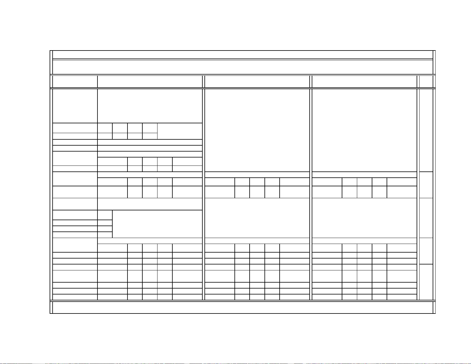
SERVICE DATA LISTS
(
)
)
)
(
)
(
)
)
)
(
)
(
)
(
)
KV-40XBR700
DX1A-2001&2000 SERVICE LIST (#3-4): CXA2150P-4 {Picture Controls: P4} (Part-2/4)
Register
No & Name
SNNR Setting
-Offset
SNNR
= 0
Data Initial/Average Settings
(32V&36V CRTs)
SNNR
SNNR
= 2
SNNR
= 3
= 1
Data Initial/Average Settings
(32V&36V CRTs)
Data Initial/Average Settings
(32V&36V CRTs)
#4 USHP (cont.)0134
UHF/VHF
Video1~4
#7 AXIS (Cont.
#8 UGAM (Cont.) 222 000 000
#10 GSBO (cont.
#11 GCOO
#12 GHUO
cont.
cont.
#13 UBLK (Cont.
3
U/VHF
Video1~4
2 0
UGAM
= 0
0
0
0
UHF/VHF
Video1~4
4
Picture Mode: Pro
YPbPr
YPbPr
480p
YPbPr
1080i
480i
333
Picture Mode: Standard
YPbPr
YPbPr
480p
YPbPr
480p
YPbPr
1080i
YPbPr
1080i
480i
Picture Mode: Standard
YPbPr
480i
444 111 000
P&P
P&P
P&P
3
U/VHF
Video1~4
2
UHF/VHF
Video1~4
4
Picture Mode: Movie Picture Mode: Pro
YPbPr
YPbPr
480i
480p
YPbPr
1080i
P&P
U/VHF
Video1~4
YPbPr
480i
YPbPr
480p
00
Picture Mode: Movie
YPbPr
YPbPr
480i
480p
YPbPr
1080i
P&P
UHF/VHF
Video1~4
Picture Mode: Pro
YPbPr
YPbPr
480i
480p
1
YPbPr
1080i
YPbPr
1080i
Note
P&P
0
P&P
001
#15 DCTR (Cont.
#16 DPIC
#17 DSBO
#18 ABLM
Note:
The same CXA2150 service data are used for DX1A-2001&2000.
Cont.
Cont.
Cont.
1
7
1
222 111 111
111 111 000
777 777 777
111 000 000
22
1
7
1
1
1
7
0
1
1
7
11
0
7
0
0
7
00
See
next
pages
— 30 —
Page 30
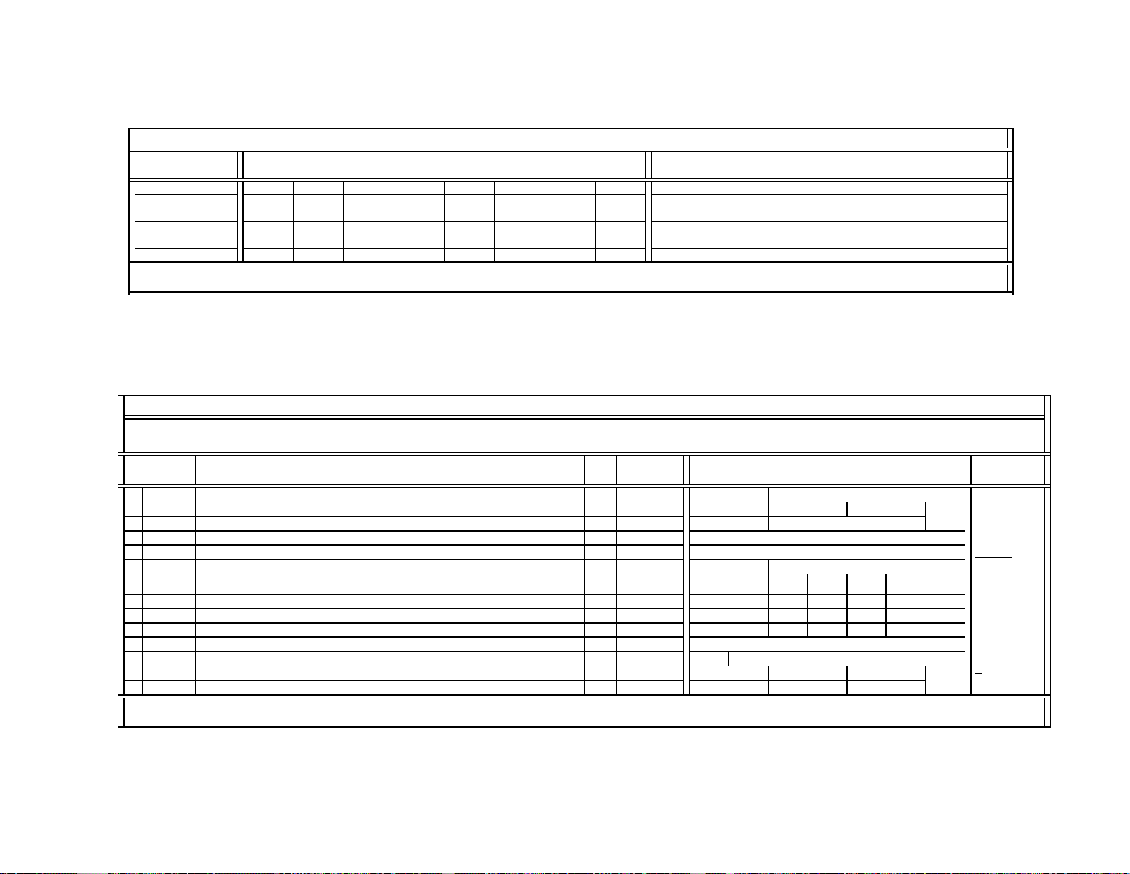
SERVICE DATA LISTS
(
)
(
)
(
)
0~15
)
0~255
0~31
0~31
0~15
(7)
0~7~15
A
0 (Not used)
Video1~4
Register
No & Name
#15 DCTR (Cont.) 32221111
#16 DPIC
#17 DSBO
#18 ABLM
Note:
The same CXA2150 service data are used for DX1A-2001&2000.
Cont.
Cont.
Cont.
DX1A-2001&2000 SERVICE LIST (#3-4): CXA2150P-4 {Picture Controls: P4} (Part-3/4)
Data Initial/Average Settings
(32V&36V CRTs)
UBLK = 7 UBLK = 6 UBLK = 5 UBLK = 4 UBLK = 3 UBLK = 2 UBLK = 1 UBLK = 0
23213210
77777777
10010000
Comment
DX1A-2001&2000 SERVICE LIST (#3-4): CXA2150P-4 {Picture Controls: P4} (Part-4/4)
KV-40XBR700
Register
No & Name
19 ABLT ABL_TH: ABL correct detection Vth control
20 ABLC Control of CXA2026 {0Ch -- DAC0} (*
21 EPOF Offset for UPIC = EPOF x (UPIC/63) (for power save) --- Void Data ---
ID-1 and P&P Modes
22 SPOF Offset for UPIC = SPOF x (UPIC/64) --- Data Not Used ---
23 SCON SUB_CONTRAST: SUB PICTURE
24 CLOF Offset for UCOL 0~
25 HUOF Offset for UHUE
CXD2085 Service Controls
26 IDSW Switch for activating the selection in #27 DATA C 0, 1 0
27 DAT
Note:
The same CXA2150 service data are used for DX1A-2001&2000.
Selection of geometry-forced vertical compression modes
Control Register
Function & Link
Data
Type
Range
C 0~3
Data
Data Initial/Average Settings
(32V&36V CRTs)
0
Full
Vcomp1
0
UHF/VHF
8
~15 10 9 7
8
4
Full
0
YPbPr
YPbPr
480i
480p
864
333
Vcomp1 Vcomp2
1
66
YPbPr
1080i
Vcomp2
2
P&P
Comment
Full:
480p/960i
(4x3)
Vcomp1
:
480p/960i
(16x9)
Vcomp2
8
8
:
1080i
(16x9)
4
( ): Settings at
center
C
:
Common data
— 31 —
Page 31

SERVICE DATA LISTS
)
)
y
j
p
)
p
p
W
y
y
19 [19]
26 [26]
15 [15]
DX1A-2001&2000 SERVICE LIST (#4-1): CXA2150D-1 {Deflection Controls: D1}
Device Name: CXA2150AQ { CRT Driver / SONY } / IC201 (A-board) / P/N: 8-752-093-35 (SBorSD#: NA)
Slave Address: 86h
Register
No & Name
0
VPOS
1
VSIZ
2
VLIN
3
VSCO
V_POSITION: Vertical position (V_DRV siganl DC-bias
V_SIZE: Vertical size (V_DRV signal gain
V_LINEARITY: Vertical linearit
(Gain for V_DRV signal secondary component)
S_CORRECTION: Vertical S-correction Ad
Control Register
Function & Link
Data
Type
Data
Range
Adj.0~(31)~63
Adj.0~(31)~63
Adj. 0~(7)~15
.0~(7)~15
VSAW0_DCH/VSAW0_DCL: Vertical center adjustment
4
VCEN
5
VPIN
VSAW0_DCH: VSAW0 waveform DC component (high 2-bits)
VSAW0_DCL: VSAW0 waveform DC com
onent (low 4-bits
VSAW0_AMP: Vertical PIN adjustment
VSAW0 waveform SAW com
onent amplitude
Adj. 0~(31)~63
Adj. 0~(15)~31 15 [15]
6 NSCO VSAW1_DC: Rotation Adj. 0~(7)~15
7
HTPZ
8
ZOOM
9
APS
10
ASPT
11
SCRL
12
UVLN
13
LVLN
Note:
The same CXA2150 service data is used for DX1A-2001&2000.
VSAW1_AMP: Horizontal tra
ezoid Adj.0~(15)~31
ZOOM_SW: Zoom switch 0, 1
ASP_SW: Aspect switch 0, 1
V_ASPECT: Aspect ratio Adj. 0~63 47 47 47
V_SCROLL: Vertical scroll Adj.0~(31)~63 31 32 32
UP_VLIN: Upper vertical linearit
LO_VLIN: Lower vertical linearit
0~15
0~15
Data Initial Settings & [Average Data]
Full Vcomp1 Vcomp2
0
1
0
0
32V&36V CRTs)
(
9 [9]
8 [8]
31 [31]
15 [Copty1]
7 [7]
0
10
0
0
Comment
: 480p/960i (4x3) display
Full
: 480p/960i (16x9) display
Vcomp1
: 1080i (16x9) display
Vcomp2
Adj.
: Adjusted data
( ): Settings at center
VCEN-L(Low bit)
VCEN-H(High bit)
[Copy1]: Copy the adjusted data
for Full mode.
Either 7 or 8 can be used as the
average NSCO data.
(If both of them are not good,
please feedback to / check with
the DY attachment process.)
KV-40XBR700
— 32 —
Page 32

SERVICE DATA LISTS
[Adj
]
0~15
0~15
j
j
j
y
A
j
y
DX1A-2001&2000 SERVICE LIST (#4-2): CXA2150D-2 {Deflection Controls: D2}
Device Name: CXA2150AQ { CRT Driver / SONY } / IC201 (A-board) / P/N: 8-752-093-35 (SBorSD#: NA)
Slave Address: 86h
Register
No & Name
0
HCNT
1
HPOS
2
HSIZ
3
SLIN
4
MPIN
5
6
UCP
7
LCP
8
UXCG
9
LXCG
10
UXCP
11
LXCP
12
XCPP
13
PPH
14
VANG
15
LANG
16
VBOW
17
LBOW
18
CPY1
Note:
The same CXA2150 service data is used for DX1A-2001&2000.
HC_PARA_DC: Horizontal center Adj.0~(31)~63
H_POSITION: Horizontal position Adj. 0~(31)~63
H_SIZE: Horizontal size Adj.0~(31)~63
MP_PARA_DC: Horizontal S-correction Adj.
MP_PARA_AMP: Horizontal middle pin
PIN_AMP: Horizontal pinAd
PIN
UP_CPIN: Upper corner pinAd
LO_CPIN: Lower corner pinAd
UP_UCG: Upper extra corner pin gain 0~3
LO_UCG: Lower extra corner pin gain 0~3
UP_UCP: Upper extra corner pin position 0~3
LO_UCP: Lower extra corner pin postion 0~3
UC_POL: Extra corner pin polarit
PIN_PHASE: Pin phase Adj.0~(31)~63
AFC_ANGLE: AFC angle Adj.0~(31)~63
HC_PARA_PHASE: Linearity angle Adj.0~(31)~63
AFC_BOW: AFC bow Ad
HC_PARA_AMP: Linearit
Copy Function 1: (Set CPY1=1, then press MUTE + Enter.)
Copy all CXA2150D-2 data for Full mode to Vcomp1&2
Control Register
Function & Link
Data
Type
Range
.0~(31)~63
.0~(31)~63
.0~(31)~63
.0~(31)~63
bow Adj.0~(31)~63
Micro
Data
0, 1
0, 1
Data Initial Settings & [Average Data]
Full Vcomp1 Vcomp2
(32V&36V CRTs)
31 [31]
31
[31]
31
.-6steps
45 [45]
3 [3]
7
35 [35]
38 [38]
42 [42]
0
0
2
2
0
15 [15]
31 [31]
31 [31]
31 [31]
31 [31]
0
Comment
Full: 480p/960i (4x3) display
: 480p/960i (16x9) display
Vcomp1
: 1080i (16x9) display
Vcomp2
( ): Settings at center
Adj.
: Adjusted data
[Adj.-6steps]:
The adj. data for Vcomp2 mode
= The adj. data for Full/Vcomp1
modes - 6 steps
(32Vor36V):
Data
The data for 36V are used as the
Initial & CBA data.
From the system micro (V 2.0),
the deflection control-related
initial settings are the same as
their average data.
For engineering design use only
KV-40XBR700
— 33 —
Page 33

SERVICE DATA LISTS
g
0~63
g
0~63
g
g
0~15
0~15
y
g
0~31
DX1A-2001&2000 SERVICE LIST (#4-3): CXA2150D-3 {Deflection Controls: D3}
Device Name: CXA2150AQ { CRT Driver / SONY } / IC201 (A-board) / P/N: 8-752-093-35 (SBorSD#: NA)
Slave Address: 86h
Register
No & Name
0
HBLK
1
LBLK
2
RBLK
3
VBLK
4
TBLK
5
BBLK
6
VCMP
7
HCMP
8
ACMP
9
PCMP
10
AFCM
11
VFRQ
12
VON
13
JUMP
14
VDJP
15
VDST
16
EWDC
17
AKBT
Note:
The same CXA2150 service data is used for DX1A-2001&2000.
HBLK_SW: Horizontal blanking switch 0, 1
LEFT_BLK: Left blankin
RIGHT_BLK: Right blankin
VBLK_SW: Vertical blanking switch 0, 1 1
UP_BLK: Top blankin
LO_BLK: Bottom blankin
V_COMP: Vertical compensation
H_COMP: Horizontal compensation
AFC_COMP: AFC compensation 0~7 0
PIN_COMP: Pin compensation 0~7 0
AFC_MODE: AFC loop gain 0~3 2
V_FREQ: Vertical frequenc
V_ON: Vertical drive on 0, 1
JMP_SW: Reference pulse jump swtich 0, 1 0
VDRV_SW: Vertical drive jump switch 0, 1 0 0 1
RST_SW: Vertical drive start switch 0, 1 0 0 1
EW_DC: Pin DC level shift 0, 1 0
AKBTIM: AKB timin
Control Register
Function & Link
Data
Type
Data
Range
0~(7)~15 3 8 12
0~(7)~15 8 13 13
0~3
Data Initial/Average Settings
(32V&36V CRTs)
Full Vcomp1 Vcomp2
1
43
29
50
27
Full: 480p/960i (4x3) display
Vcomp1
Vcomp2
1
( ): Settings at center
000
0
0
0
0
3
1
1
1
0
20 20 10
KV-40XBR700
Comment
: 480p/960i (16x9) display
: 1080i (16x9) display
— 34 —
Page 34

SERVICE DATA LISTS
(
)
(
)
(
)
0~3
g
g
0~3
0~3
0, 1
)
0, 1
)}
0, 1
KV-40XBR700
DX1A-2001&2000 SERVICE LIST (#5):
CXA2151Q
Device Name: CXA2151Q { Component I/F & Sync Separation / SONY } / IC3001 (B-board) / P/N: 8-752-093-84 (SD#: S00302B)
Slave Address: 84h
Register
No & Name
0
MTRX
1
GAIN
2
CBGN
3
4
HWID
5
HSEP
6
TEST
7
FRGB
8
HMSK
Note:
The same CXA2151 service data is used for DX1A-2001&2000.
MAT_OUT: Selection of color matrix conversion types
GAIN_SEL:
Selection of output signals for SELYOUT, SELCBOUT, SELCROUT
YGAIN, CBGAIN, CRGAIN:
ain control of SELYOUT, SELCBOUT, & SELCROUT
The
VTC
V_TC: Settin
of Vsync separation time constant C
H_WIDTH: Setting of the output pulsewidth of SELHOUT C
HSEP_SEL: Setting for the sync separation system
TEST: Test mode selection (for device tests
The forced RGB selection (for tests)
{0: MAT_OUT = MTRX (#0), 1: MAT_OUT = MTRX (#3
Hsync masking in vertical retrace
Control Register
Function & Link
Data
Data
Type
Range
Micro
C 0~3 0
C 0~15 9
C
C 0, 1 0
Data Initial/Average Settings
32V&36V CRTs)
(
480i
15.75 KHz
480p
31.50 KHz
1080i
33.75 KHz
001
1
1
Video5 Video6 Sub
000
0
Full Vcomp1 Vcomp2
1
0
Comment
Video5&6:
YPbPr-480i/480p/1080i inputs
: 480i input from the sub-channel
Sub
Full
: 480p/960i (4x3) display
: 480p/960i (16x9) display
Vcomp1
: 1080i (16x9) display
Vcomp2
C
: Common data
— 35 —
Page 35

SERVICE DATA LISTS
]
Y
pp
]
Y
j
]
]
]
]
]
]
]
)
)
31 [31]
31 [31]
31 [31]
31 [31]
31 [31]
31 [31]
48 [48]
31 [31]
31 [31]
31 [31]
DX1A-2001&2000 SERVICE LIST (#6): D-CONV / CXA8070
Device Name: CXA8070AP { DY-Convergence Control / SONY } / IC5513 (D-board) / P/N: 8-759-595-52 (SB#: V1718)
Slave Address: DEh
Register
No & Name
0
SBHS
1
2
3
RSAP
4
RUBW
5
RLBW
6
LSAP
7
LUBW
8
LLBW
9
CADJ
10
CPY2
Note:
The same CXA8070 service data is used for DX1A-2001&2000.
DC AMP3: DC shift Adj. 0~63 31 [31
VCA9: U
BWU
VCA10: Lower Y-bow Ad
BWL
er Y-bow Adj. 0~63 31 [31
DC AMP2: Right H-AMP Adj. 0~63 31 [31
VCA5: Right upper bow Adj. 0~63 31 [31
VCA6: Right lower bow Adj. 0~63 31 [31
DC AMP1: Left H-AMP Adj. 0~63 31 [31
VCA1: Left upper bow Adj. 0~63 31 [31
VCA2: Left lower bow Adj. 0~63 31 [31
DC AMP4: Offset adjustment (ADJ
Copy Function 2: (Set CPY2=1, then press MUTE +
Enter.
Control Register
Function & Link
Data
Data
Type
Range
. 0~63 31 [31
Adj. 0~63
Micro
0, 1
Data Initial Settings & [Average Data]
Full Vcomp1 Vcomp2
32V&36V CRTs)
(
0
Comment
Full: 480p/960i (4x3) display mode
: 480p/960i (16x9) display mode
Vcomp1
: 1080i (16x9) display mode
Vcomp2
Adj.
: Adjusted data
From the system micro (V 2.0),
the deflection control-related initial settings
are the same as their average data.
For engineering design use only
KV-40XBR700
— 36 —
Page 36

SERVICE DATA LISTS
]
23 [23]
]
25 [25]
]
34 [12]
Y
is used as Initial/CBA data.
g
)
]
DX1A-2001&2000 SERVICE LIST (#7): CXA2026AS
Device Name: CXA2026AS { DQP Control / SONY } / IC5511 (D-board) / P/N: 8-752-074-64 (SD#: S95610B)
Slave Address: 8Eh
Register
No & Name
0
DFON
1
DQP
2
3
DQPD
4
QPDV U.CBOW, L.CBOW: DQP dc-level vertical modulation
5
DVS
6
QPD
7
DQPA
8
QPAV
9
AVS
10
NORM
11
CPY3
12
200V
Note:
The same CXA2026 service data is used for DX1A-2001&2000.
SW0: DF on/off switch C 0, 1 0
PWM: DQP phase Adj. 0~63 23 [23
DAC1: DF phase Adj. 0~63 25 [25
DF
H.AMP: DQP dc-level Adj. 0~63 34 [12
U.CBOW, L.CBOW: DQP dc-level tilt 0~(3)~7 0 0
U.MBH,L.MBH: DQP dc-level at top & bottom areas 0~63 15 15
DC SHIFT: DQP amplitude Adj. 0~63 13 [10] 13 [10] 13 [10]
U.YBOW, LYBOW: DQP amplitude vertical modulation 0~63 38 34
U.YBOW, LYBOW: DQP amplitude tilt 0~7 3 3
SW1: 0, 1 0 0
Copy Function 3: (Set CPY3=1, then press MUTE +
Enter.
H.DUTY, H.TILT: 200V regulator adjustment Adj. 0~63 31 [31
Control Register
Function & Link
Data
Type
Data
Range
Data Initial Settings & [Average Data]
0~63 35 31
Micro
0, 1 0
Full Vcomp1 Vcomp2
(32V&36V CRTs)
Comment
: 480p/960i (4x3) display mode
Full
: 480p/960i (16x9) display mode
Vcomp1
: 1080i (16x9) display mode
Vcomp2
: Common data
C
: Adjusted data
Adj.
U.CBOW = QPDV + DVS
L.CBOW = QPDV - DVS
( ): Settings at center
Data (36V)
From the system micro (V 2.0), most
deflection control-related initial settings
are the same as their avera
U.YBOW = QPAV + AVS
L.YBOW = QPAV - AVS
For engineering design use only
e data.
KV-40XBR700
— 37 —
Page 37

SERVICE DATA LISTS
DX1A-2001&2000 SERVICE LIST (#8): Audio Processing (AP) / BH3868AFS
Device Name: BH3868AFS { Audio Processor / ROHM } / IC7001 (A-board) / P/N: 8-759-678-92 (SBorSD#: NA)
Slave Address: 82h
Register
No & Name
0
SVOL
1
SBAL
2
SBAS
3
STRE
4
BBLP
5
BBHP
6
SREF
7
AGC
8
BBE
Note:
The same AP service data is used for DX1A-2001&2000.
Control Register
Function & Link
Data
Type
Data
Range
Data Initial/Average Setting
(32V&36V CRTs)
Volume: Offset for Volume 0~3 0
Balance: Offset for Balance 0~(3)~7 7
Bass: Offset for Bass 0~(3)~7 10
Treble: Offset for Treble 0~(3)~7 3
BBE lowpass filter 0~15 6
BBE highpass filter 0~15 7
Surround effect 0~7 11
Auto gain control 0, 1 0
BBE on/off 0, 1 1
( ): Settings at center
KV-40XBR700
Comment
DX1A-2001&2000 SERVICE LIST (#9):
TruSurround (TRUS) / NJM2180
Device Name: NJM2180M { TruSurround 3D-Audio Processor / JRC } / IC4101 (S-board) / P/N: 8-759-686-15 (SB#: V9072)
Device Control: Controlled via CXA1315M (Audio Control D/A, IC4103/S-board, Slave Address: 48h) / P/N: 8-752-059-23 (SD#: S88Z45B)
Register
No & Name
0
1
DMY1
Note:
The same TRUS service data is used for DX1A-2001&2000.
TruSurround effect selection 0~3 2
TS
Dummy data (No functions) C 0~255 0
Control Register
Function & Link
Data
Type
Data
Range
Data Initial/Average Setting
(32V&36V CRTs)
Comment
C: Common data
DMY1 is used to fulfil the minimum requirement of 2 control items in each service control
category.
— 38 —
Page 38

SERVICE DATA LISTS
play
play
p
p
y
y
DYSD
y
p
p
10
p
11
p
12
(
13
(
)
14
p
15
p
16
p
17
p
play
)
DX1A-2001* SERVICE LIST (#10): MID1 (Common Data)
Device Name: CXD9509AQ { MID-XA / Fujitsu & SONY } / IC3408 (B-board) / P/N: 8-759-672-57 (SBorSD#: NA)
Slave Address: 2Eh { Controlled through MID-XA Micro (IC3090/B-board, Slave Address: 64h) / P/N: 6-800-050-01 (SB#: V4216) }
MID-XA Micro (MASK type): MB94918RPF-G-137-BND, MID-XA Software: Version 12/08/00, (P/N: 6-800-050-01)
Register
No & Name
0
DHPH
1
DVPH
2
DHAR
3
DVAR
4
DHPW
5
DVPW
6
DYCD
7
8
MDHP
9
MDVP
MDHS
MDVS
MLHP
MLVP
SDHP
SDVP
SDHS
SDVS
18
DPSW
19
MDL0
Note:
* These MID1 settings are used for DX1A-2001 ONLY. The DPSW setting was changed from 1 in DX1A-2000 to 0 in DX1A-2001.
Horizontal phase of the active display area d_h_phase
Vertical phase of the active display area d_v_phase
Horizontal size of the active dis
Vertical size of the active dis
Horizontal
Vertical
Dela
of YC signal output d_yc_dela
Delay of YS signal output d_ys_dela
Horizontal position of the main picture m_dsp_hpos 0~255 12
Vertical
Horizontal size of the main
Vertical size of the main
Horizontal position of the multi pictures) 0~255
Vertical position of the multi pictures
Horizontal
Vertical
Horizontal size of the sub
Vertical size of the sub
Switch of dis
Model selection 0 (0: 16x9, 1: 4x3
Control Register
Function & Link
area d_h_area
area d_v_area
ulse width d_h_pwidth
ulse width d_v_pwidth
Register Name
(Software)
Data
Type
C
C
C
C
C
C
C
C
Data
Range
0~255
0~63
0~255
0~255
0~63
0~7
0~63
0~7
Data Initial/Average Setting
(32V/36V/40V CRTs)
MID Mode: All
(Single & P&P & Favorite)
91
20
240
135
27
7
2
1
MID Mode: Signle & Favorite
Single
480i&
Single
1080i
Favorite
33
osition of the main picture m_dsp_vpos 0~255 32 8 14
icture m_dsp_hsiz 0~255 158
230
icture m_dsp_vsiz 0~255 120 135 106
MID Mode: P&P & Favorite
54
0~255
osition of the sub picture s_dsp_hpos 0~255
osition of the sub picture s_dsp_vpos 0~255
icture s_dsp_hsiz 0~255
icture s_dsp_vsiz 0~255
(Single & P&P & Favorite)
output PLL dsp_pll_sw C 0, 1
C 0, 1
31
MID Mode: Favorite
172
14
61
41
MID Mode: All
0
0
C: Common data
0: MUST be used in DX1A-2001, 1: Used in DX1A-2000
KV-40XBR700
Comment
— 39 —
Page 39

SERVICE DATA LISTS
DRHP
0~255
0~255
)
0~255
)
0~255
)
)
y
Y
Y
p
0~255
y
)
0~255
MID3 (VDO-in Data)
DX1A-2001&2000 SERVICE LIST (#11): MID2 (DRC-in Data)
Device Name: CXD9509AQ { MID-XA / Fujitsu & SONY } / IC3408 (B-board) / P/N: 8-759-672-57 (SBorSD#: NA)
Slave Address: 2Eh { Controlled through MID-XA Micro (IC3090/B-board, Slave Address: 64h) / P/N: 6-800-050-01 (SB#: V4216) }
MID-XA Micro (MASK type): MB94918RPF-G-137-BND, MID-XA Software: Version 12/08/00, (P/N: 6-800-050-01)
Register
No & Name
0
1
DRHS
2
DRVP
3
DRVS
Note:
The same MID2 service data is used for DX1A-2001&2000.
Horizontal position of the active display area (DRC-in) drc_hactv_pos 0~255 120 116 131 129 137 138 136
Hsize of the active display area (DRC-in) drc_hactv_siz 0~255 174 174 167 167 168 165 165
Vposition of the active display area (DRC-in) drc_vactv_pos 0~63 38 38 53 53 53 53 53
Vertical size of the active display area (DRC-in) drc_vactv_siz 0~255 120 120 112 112 112 112 112
Control Register
Function & Link
Register Name
(Software)
Data
Type
Data
Range
Data Initial/Average Setting
(32V&36V CRTs)
MID Mode: Single MID Mode: P&P & Favorite MID Mode: Freeze
YC
480i
YPbPr
480i
YC
480i
YPbPr
480i
YC
480i-(R)
KV-40XBR700
YC
480i
YPbPr
480i
DX1A-2001&2000 SERVICE LIST (#12):
(Part-1/2)
Device Name: CXD9509AQ { MID-XA / Fujitsu & SONY } / IC3408 (B-board) / P/N: 8-759-672-57 (SBorSD#: NA)
Slave Address: 2Eh { Controlled through MID-XA Micro (IC3090/B-board, Slave Address: 64h) / P/N: 6-800-050-01 (SB#: V4216) }
MID-XA Micro (MASK type): MB94918RPF-G-137-BND, MID-XA Software: Version 12/08/00, (P/N: 6-800-050-01)
Register
No & Name
0
VDHP
1
VDHS
2
VDVE
3
VDVS
4
VDVO
5
VCPO
6
VCWD
7
VYCD
8
VSTP
9
VSTT
10
VHSC
Note:
The same MID3 service data is used for DX1A-2001&2000.
Horizontal position of the active display area (VDO-in) vdo_hactv_pos
Horizontal pixel size of the active display area (VDO-in) vdo_hactv_pos
Vertical even position of the active display area (VDO-in) vdo_vactv_evn 0~63 39 24
Vertical line size of the active display area (VDO-in
Vertical odd position of the active display area (VDO-in) vdo_vactv_odd 0~3 0000
Clamp pulse output timing (VDO-in
Clamp pulse width (VDO-in
Analog input YC delay (VDO-in
PD stop line count of external PLL (VDO-in) vdo_pll_sto
PD start line count of external PLL (VDO-in) vdo_pll_strt 0~15 7 0
Horizontal s
nc cycle (VDO-in
Control Register
Function & Link
Register Name
(Software)
Data
Type
Data
Range
Data Initial/Average Setting
(32V&36V CRTs)
MID Mode: Single
YPbPr
480P
Dummy
480i
122 179
159 199
vdo_vactv_pos
vdo_clp_pos
YC
480i
95 70 40 90
129 56
YPbPr
480P
YPbPr
1080i
Dummy
480i
vdo_clp_wdt 0~7 3333
vdo_yc_dela
0~63 0000
PbPr
480P
PbPr
1080i
119 160
MID Mode: All
(Single & P&P & Favorite)
vdo_hsync_cyc
130
Comment
Dummy-480i settings are used
for No Signal cases.
These settings continue to the
next page.
— 40 —
Page 40

SERVICE DATA LISTS
)
(
)
(
)
(
)
(M)
1
MHLC
)
3
)
0
)
0
0
p
1
MHYE
0
(M
0
MHCL
p
1
0
MVYR
0
p
1
0
0
p
1
MVCE
0
Register
No & Name
#0 VDHP (cont.
#1 VDHS
#2 VDVE
#3 VDVS
Note:
The same MID3 service data is used for DX1A-2001&2000.
cont.
cont.
cont.
DX1A-2001&2000 SERVICE LIST (#12): MID3 (VDO-in Data) (Part-2/2)
Data Initial Setting
(32V&36V CRTs)
MID Mode: P&P / Favorite
YC
480i
YPbPr
480P
YPbPr
1080i
Dummy
480i
197 127 91 179 131 98 179
219 154 151 199 153 149 199
24 53 37 24 53 37 24
56 112 126 56 112 126 56
Data Initial Setting
(32V&36V CRTs)
MID Mode: FREEZE
YPbPr
480P
YPbPr
1080i
Dummy
480i
KV-40XBR700
Comment
Dummy-480i settings are used for No Signal cases.
DX1A-2001&2000 SERVICE LIST (#13):
MID5 (Picture Data: MIDE) (Part-1/4)
Device Name: CXD9509AQ { MID-XA / Fujitsu & SONY } / IC3408 (B-board) / P/N: 8-759-672-57 (SBorSD#: NA)
Slave Address: 2Eh { Controlled through MID-XA Micro (IC3090/B-board, Slave Address: 64h) / P/N: 6-800-050-01 (SB#: V4216) }
MID-XA Micro (MASK type): MB94918RPF-G-137-BND, MID-XA Software: Version 12/08/00, (P/N: 6-800-050-01)
Register
No & Name
Control Register
Function & Link
Settings for P&P (Main)
Register Name
(Software)
Data
Type
Data
Range
Data Initial/Average Setting
(32V&36V CRTs)
UHF/VHF & CVideo YPbPr-480i (DVD)
Pro Movie Standard Vivid Pro Movie Standard Vivid
Data Initial/Average Setting
(32V&36V CRTs)
0 POP Selection of service data tables (Table #: 0~15) 0~15 0123 4567
1
MHLY
2
3
MVLY
4
MVLC
5
MHYR
6
MHYL
7
8
MHYO
9
MHCR
10
11
MHCE
12
MHCO
13
14
MVYL
15
MVYE
16
MVCR
17
MVCL
18
Note:
The same MID5 service data is used for DX1A-2001&2000.
Y coefficient code of Horizontal LPF
C coefficient code of Horizontal LPF (M
Y coefficient code of Vertical LPF (M
C coefficient code of Vertical LPF (M
Y coreing code of horizontal enhancement (M) m_henh_ycore 0~3 0000 0
Y cliping code of horizontal enhancement (M) m_henh_ycli
Y level code of horizontal enhancement (M) m_henh_yenh 0~74000 3
Y coefficient code of horizontal enhancement
C coreing code of horizontal enhancement (M) m_henh_ccore 0~3 0000 0
C cliping code of horizontal enhancement (M) m_henh_ccli
C level code of horizontal enhancement (M) m_henh_cenh 0~7 0000 0
m_hlpf_ycoef 0~3 1111 1
m_hlpf_ccoef 0~3 3333 3
m_vlpf_ycoef 0~3 0000 0
m_vlpf_ccoef 0~3 0000 0
11
33
00
00
00
0~31111 1
11
00
m_henh_ycof 0, 1 1111 1111
00
0~31111 1
11
00
C coefficient code of horizontal enhancement (M m_henh_ccof 0, 1 1111 1111
Y coreing code of vertical enhancement (M) m_venh_ycore 0~3 0000 0
Y cliping code of vertical enhancement (M) m_venh_ycli
0~31111 1
Y level code of vertical enhancement (M) m_venh_yenh 0~70000 0
C coreing code of vertical enhancement (M) m_venh_ccore 0~3 0000 0
C cliping code of vertical enhancement (M) m_venh_ccli
0~31111 1
C level code of vertical enhancement (M) m_venh_cenh 0~7 0000 0
22
11
25
00
11
00
See
the
next
page.
— 41 —
Page 41

SERVICE DATA LISTS
(
)
(
)
(
)
(
)
(
)
(
)
(
)
(
)
(
)
(
)
(
)
(
)
(
)
(
)
(
)
(
)
(
)
(
)
KV-40XBR700
DX1A-2001&2000 SERVICE LIST (#13): MID5 (Picture Data: MIDE) (Part-2/4)
Register
No & Name
Data Initial/Average Setting
(32V&36V CRTs)
Pro Movie Standard Vivid Pro Movie Standard Vivid
Data Initial/Average Setting
(32V&36V CRTs)
YPbPr-1080iYPbPr-480p
#0 POP (cont.) 8 9 10 11 12 13 14 15
#1 MHLY
#2 MHLC
#3 MVLY
#4 MVLC
#5 MHYR
#6 MHYL
#7 MHYE
#8 MHYO
#9 MHCR
#10 MHCL
#11 MHCE
#12 MHCO
#13 MVYR
#14 MVYL
#15 MVYE
#16 MVCR
#17 MVCL
#18 MVCE
Note:
The same MID5 service data are used for DX1A-2001&2000.
cont.
cont.
cont.
cont.
cont.
cont.
cont.
cont.
cont.
cont.
cont.
cont.
cont.
cont.
cont.
cont.
cont.
cont.
1111 1111
3333 3333
0000 0000
0000 0000
0000 0000
1111 1111
4000 4000
1111 1111
0000 0000
1111 1111
0000 0000
1111 1111
0022 0000
1111 1111
0025 0000
0000 0000
1111 1111
0000 0000
Comment
— 42 —
Page 42
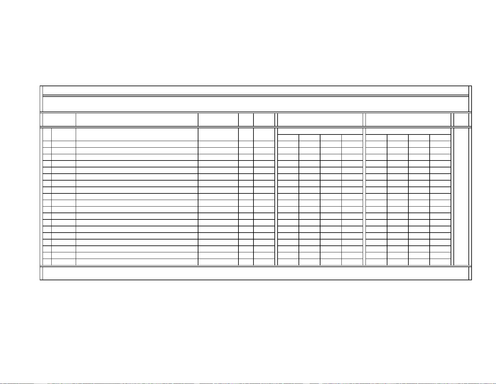
SERVICE DATA LISTS
)
0~15
Y
)
)
Y
)
)
p
g
ping
p
(S)
(S
p
p
(S)
KV-40XBR700
DX1A-2001&2000 SERVICE LIST (#13): MID5 (Picture Data: MIDE) (Part-3/4)
Register
No.&Name
Control Register
Function & Link
Settings for P&P (Sub)
0
POP
19
SHL
20
SHLC
21
SVL
22
SVLC
23
SHYR
24
SHYL
25
SHYE
26
SHYO
27
SHCR
28
SHCL
29
SHCE
30
SHCO
31
SVYR
32
SVYL
33
SVYE
34
SVCR
35
SVCL
36
SVCE
Note:
The same MID5 service data is used for DX1A-2001&2000.
Selection of service data tables (Table #: 0~15
Y coefficient code of Horizontal LPF (S
C coefficient code of Horizontal LPF (S
Y coefficient code of Vertical LPF (S
C coefficient code of Vertical LPF (S
Y coreing code of horizontal enhancement (S) s_henh_ycore 0~3 0000 0000
Y cliping code of horizontal enhancement (S) s_henh_ycli
Y level code of horizontal enhancement (S) s_henh_yenh 0~70000 0000
Y coefficient code of horizontal enhancement (S s_henh_ycof 0, 1 0000 0000
C corein
C cli
code of horizontal enhancement (S) s_henh_ccore 0~3 0000 0000
code of horizontal enhancement (S) s_henh_ccli
C level code of horizontal enhancement
C coefficient code of horizontal enhancement
Y coreing code of vertical enhancement (S) s_venh_ycore 0~3 0000 0000
Y cliping code of vertical enhancement (S) s_venh_ycli
Y level code of vertical enhancement (S) s_venh_yenh 0~70000 0000
C coreing code of vertical enhancement (S) s_venh_ccore 0~3 0000 0000
C cliping code of vertical enhancement (S) s_venh_ccli
C level code of vertical enhancement
Register Name
(Software)
Data
Type
Data
Range
Data Initial/Average Setting
(32V&36V CRTs)
UHF/VHF & CV
Pro Movie Standard Vivid Pro Movie Standard Vivid
Data Initial/Average Setting
(32V&36V CRTs)
YPbPr-480i (DVD)
0123 4567
s_hlpf_ycoef 0~7 0000 0000
s_hlpf_ccoef 0~7 0000 0000
s_vlpf_ycoef 0~7 0000 0000
s_vlpf_ccoef 0~7 0000 0000
0~30000 0000
0~30000 0000
s_henh_cenh 0~7 0000 0000
s_henh_ccof 0, 1 0000 0000
0~30000 0000
0~30000 0000
s_venh_cenh 0~7 0000 0000
See
the
next
page.
— 43 —
Page 43

SERVICE DATA LISTS
)
(
)
(
)
(
)
(
)
(
)
(
)
(
)
(
)
(
)
(
)
(
)
(
)
(
)
(
)
(
)
(
)
(
)
(
)
p
KV-40XBR700
DX1A-2001&2000 SERVICE LIST (#13): MID5 (Picture Data: MIDE) (Part-4/4)
Register
No.&Name
#0 POP (cont.
#19 SHLY
#20 SHLC
#21 SVLY
#22 SVLC
#23 SHYR
#24 SHYL
#25 SHYE
#26 SHYO
#27 SHCR
#28 SHCL
#29 SHCE
#30 SHCO
#31 SVYR
#32 SVYL
#33 SVYE
#34 SVCR
#35 SVCL
#36 SVCE
Note:
The same MID5 service data are used for DX1A-2001&2000.
cont.
cont.
cont.
cont.
cont.
cont.
cont.
cont.
cont.
cont.
cont.
cont.
cont.
cont.
cont.
cont.
cont.
cont.
Data Initial/Average Setting
(32V&36V CRTs)
YPbPr-480p YPbPr-1080i
Pro Movie Standard Vivid Pro Movie Standard Vivid
8 9 10 11 12 13 14 15
0000 0000
0000 0000
0000 0000
0000 0000
0000 0000
0000 0000
0000 0000
0000 0000
0000 0000
0000 0000
0000 0000
0000 0000
0000 0000
0000 0000
0000 0000
0000 0000
0000 0000
0000 0000
Data Initial/Average Setting
(32V&36V CRTs)
Comment
DX1A-2001* SERVICE LIST (#14):
On-Screen Display (OSD)
Device Name: M306V2ME-153FP (V1.0) { System Micro (MASK type) / Mitsubishi } / IC701 (A-board)
Slave Address: 60h
System Micro (MASK type): M306V2ME-153FP, Sys-Software: Version 1.0, P/N: 6-800-051-01 (SB#: V9091)
Register
No & Name
0
HPOS
1
HPOF
2
VPOS
3
VPOT
Note:
* This OSD settings are used for DX1A-2001 ONLY. (DX1A-2000 uses two OSD settings based on two versions of system micros.)
OSD horizontal
Horizontal position for Favorite mode C 0~255
OSD vertical position C 0~255 5
Vertical position for P&P (Twin) mode C 0~255 32
Control Register
Function & Link
Data
Type
Data
Range
Data Initial/Average Setting
osition C 0~255 23
(32V&36V CRTs)
33
Comment
C: Common data
— 44 —
Page 44

SERVICE DATA LISTS
g
)
)
(
(
(
MIDD
g
SNNR Settings Based on WSL Data
SNNR Settings Based on WSL Data
DX1A-2001&2000 SERVICE LIST (#15): SNNR
Related Control Devices:
mPD64082 { 3D-Comb / NEC } / IC3501 (BC-board) / Slave Address: B8h
CXA2103Q { Chroma Decoder / SONY } / IC3048 (B-board) / Slave Address: 9Ah (Main)
CXA2150Q { CRT Driver / SONY } / IC201 (A-board) / Slave Address: 86h
Register
No & Name
0
SNNR
SNNR data settin
Selection of SNNR data settings;
1 SNFX
0: Set SNNR automatically according to WSLT value (read
data
2
WSLT
Noise level detection data thretholds for SNNR data (read data
SNNR data used as the (-) offset settings
SNNR = 0/1/2/3 @ WSLT £ 0/31/63/127, respectively 0~3 0123
3
CPFG Related to 3D-COMB
4
CPFT Related to 3D-COMB (mPD64082) / #18 YPFT settings
5
CCOR Related to 3D-COMB
6
CHCG Related to 3D-COMB (mPD64082) / #21 YHCG settings
7
CAPG Related to 3D-COMB
8
3SHP Related to CXA2103 / #6 SHAP settings
9
10
5SHP Related to CXA2150P-4 / #4 USHP settings
11
5YF1 Related to CXA2150P-3 / #10 F1LV settings
12
5CDS Related to CXA2150P-3 / #11 CDSP settings
13
5LTI Related to CXA2150P-3 / #12 LTLV settings
14
5CTI Related to CXA2150P-3 / #14 CTLV settings
15
5VML Related to CXA2150P-3 / #1 UVML settings
16
5VMC Related to CXA2150P-3 / #3 VMCR settin
Note:
The same SNNR service data is used for DX1A-2001&2000.
Please refer to the part numbers and SBorSD numbers given in the service list for these devices.
SNNR data used as the direct settings
SNNR data used as the (-) offset settings
Related to CXA2150P-3 / #19 MIDE settings
SNNR data used as the (+) offset settings
Control Register
Function & Link
mPD64082) / #19 YPFG settings
mPD64082) / #20 YHCO settings
mPD64082) / #16 VAPG settings
s
Data
Type
Data
Range
Data Initial/Average Setting
32V&36V CRTs
0~3 0
C 0, 1 0
WSLT Data / Threthold Range
0~255 0~30 31~62 63~126 127~255
( - Offset Data)
------ 0123
------ 0000
------
------ 0111
------ 1111
------ 0000
------ 0123
------ 0123
------ 0134
------ 0123
------ 0000
------ 0000
------ 0000
------ 0000
( + Offset Data)
------ 0 + 1 + 2 + 3
KV-40XBR700
Comment
C: ComMon data
— 45 —
Page 45
SERVICE DATA LISTS
p
)
p
)
g
K
A
DX1A-2001&2000 SERVICE LIST (#16): ID-1 Detection (ID1)
Device Name: CXD2085M { ID-1 Decoder / SONY } / IC3603 (B-board) / P/N: 8-752-395-13 (SD#: S98511B)
Slave Address: 40h
Register
No & Name
Control Register
Function & Link
Data
Type
Data
Range
Data Initial/Average Setting
(32V&36V CRTs)
KV-40XBR700
Comment
0
XJGL
1
LNJI
Note:
The same ID1 service data is used for DX1A-2001&2000.
Other service controls related to CXD2085 (IDSW & DATA) are lised in Service List (CXA2150P-4) for easier engineering adjustment.
XJGLK: Setting for memorizing or not the ID-1 detection status
when the VTR in Fast Forward (FF) or Rewind (REW) mode
C 0, 1 0
LNJ1: Setting for the multi/single-line ID-1 detection C 0, 1 0
: Common data
C
DX1A-2001&2000 SERVICE LIST (#17): Closed Caption Display & Parental Control (CCD&VCHIP)
Device Name: CXP85840A-039Q { CCD&Vchip Micro (MASK type) / SONY } / IC3602 (Main) & IC3601 (Sub) (B-board) / P/N: 8-752-916-40 (SD#: S97739B)
Slave Address: 68h (Main) & 6Ch (Sub)
CCD&Vchip Micro Software: Version 2.14
Register
No & Name
0
HPRM
1
HPRS
2
RND
3
CCDI
4
CRIP
5
CRIT
6
CHM
7
FPOL
8
LANG
9
DAT
10
VCHIP
Note:
The same CCD&VCHIP service data is used for DX1A-2001&2000.
Horizontal
Horizontal
OSD roundin
Interuption control C 0~7 3
CRI count & parity count C 0~7 4
Charge/Discharge timing control for slice voltage level C 0, 1 0
Horizontal mask width C 0~63 42
Field polarity selection C 0, 1 1
Switch for CCD service/test data C 0, 1 0
Selection of Vchip controls C 0, 1 0
Control Register
Function & Link
osition of CCD (Main
osition of CCD (Sub
Data
Type
Data
Range
Data Initial/Average Setting
(32V&36V CRTs)
C 0~255 46
C 0~255 46
control C 0, 1 1
C 0~3 0
Comment
C: Common data
0: MASK-type micro, 1: OTP-type micro
— 46 —
Page 46

SERVICE DATA LISTS
DLY1
DLY2
DLY3
127
255
202
251
177
DX1A-2001&2000 SERVICE LIST (#18): OPTIONS (OP)
Device Name: M306V2ME-153FP (V1.0) { System Micro (MASK type) / Mitsubishi } / IC701 (A-board)
Slave Address: 60h
System Micro (MASK type): M306V2ME-153FP, Sys-Software: Version 1.0, P/N: 6-800-051-01 (SB#: V9091)
Register
No & Name
0
1
2
3
RAMW
Note:
The same OP service data is used for DX1A-2001&2000.
AC-RLY to MAIN-RLY timing = DLY1 x 50 ms C 0~15 4
Power-On Mute timing = DLY2 x 50 ms C 0~31 12
DGC-RLY to MAIN-RLY timing = DLY3 x 50 ms C 0~15 7
RAM monitor on/off C 0, 1 0
Control Register
Function & Link
Data
Type
Data
Range
Data Initial/Average Setting
(32V&36V CRTs)
KV-40XBR700
Comment
C: Common data
DX1A-2001* SERVICE LIST (#19):
IDENTIFICATION (ID)
Device Name: M306V2ME-153FP (V1.0) { System Micro (MASK type) / Mitsubishi } / IC701 (A-board)
Slave Address: 60h
System Micro (MASK type): M306V2ME-153FP, Sys-Software: Version 1.0, P/N: 6-800-051-01 (SB#: V9091)
Register
No & Name
Shipping Destination-related Settings
0
1
2
3
4
5
6
7
Note:
* These ID settings are used for DX1A-2001 ONLY. (DX1A-2000 uses different ID settings.)
The system micro name, software&patch versions, and the status of NVM devices are displayed only when in this service catergory (#19): ID.
Selection of OSD languages & color systems 0~255 25
ID0
Selection of composite & s-video inputs 0~255
ID1
Selection of audio-related controls 0~255
ID2
Selection of basic system settings 0~255
ID3
Selection of basic system settings 0~255
ID4
Selection of advanced system settings 0~255
ID5
Selection of sub picture-related settings 0~255 54
ID6
Selection of some reserved settings 0~255 88
ID7
Control Register
Function & Link
Data
Type
Data
Range
Comment
KV-38DRC2
KV-38DRC2C
— 47 —
Page 47
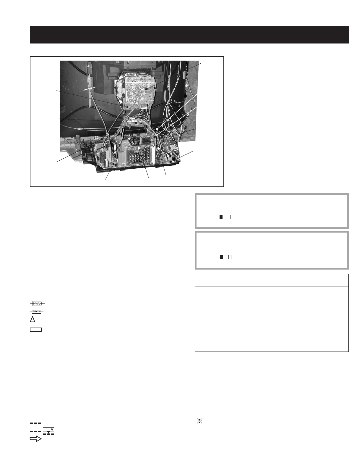
5-1. CIRCUIT BOARDS LOCATION
W Board
DH Board
SECTION 5: DIAGRAMS
C Board
HB Board
B Board
BC Board
KV-40XBR700
Circled numbers are waveform references.
The components identifi ed by
schematic diagram have been carefully factory-selected
for each set in order to satisfy regulations regarding
X-ray radiation. Should replacement be necessary,
replace only with the value originally used (Refer to
Safety Related Adjustments on page 18).
When replacing components identifi ed by
necessary adjustments as indicated. If the results do
not meet the specifi ed value, change the component
identifi ed by
X
and repeat the adjustment until the
specifi ed value is achieved.
X
in this basic
Y
, make the
HA Board
D Board
U Board
S Board
5-2. PRINTED WIRING BOARDS AND
SCHEMATIC DIAGRAMS
All capacitors are in µF unless otherwise noted. pF : µµF 50WV or less
are not indicated except for electrolytics and tantalums.
All electrolytics are in 50V unless otherwise specifi ed.
All resistors are in ohms. K = 1000, M = 1000K.
Indication of resistance, which does not have one for rating electrical
power, is as follows:
Pitch : 5mm
Rating electrical power :
1
/
W, 1/
W in resistance, 1/
4
4
: nonfl ammable resistor.
: fusible resistor.
: internal component.
: panel designation and adjustment for repair.
W and 1/
10
W in chip resistance.
8
A Board
When replacing the parts listed in the table below, it is
important to perform the related adjustments.
The components identifi ed by shading and ! symbol are critical for safety. Replace
only with part number specifi ed.
The symbol indicates a fast operating fuse and is displayed on the component
side of the board. Replace only with fuse of the same rating as marked.
Les composants identifi es par un trame et une marque
securite. Ne les remplacer que par une piece portant le numero specifi e.
Le symbole indique une fusible a action rapide. Doit etre remplace par une
fusible de meme yaleur, comme maque.
!
sont critiques pour la
Part Replaced (Y) Adjustment (X)
D BOARD:
IC6503, IC8001, IC8003, IC8004,
D BOARD:
RV8001, RV8002
D8004, D8014, R8016, R8021,
R8028, R8041, R8042, R8044,
R8072, R8073, R8074, R8077,
R8078, R8080, R8081, R8082,
R8091, R8095
All variable and adjustable resistors have characteristic curve B, unless
otherwise noted.
Readings are taken with a color-bar signal input.
Readings are taken with a 10M digital multimeter.
Voltages are DC with respect to ground unless otherwise noted.
Voltage variations may be noted due to normal production tolerances.
All voltages are in V.
S : Measurement impossibillity.
: B+line.
: B-line. (Actual measured value may be different).
: signal path. (RF)
— 48 —
REFERENCE INFORMATION
RESISTOR
: RN METAL FILM
: RC SOLID
: FPRD NONFLAMMABLE CARBON
: FUSE NONFLAMMABLE FUSIBLE
: RW NONFLAMMABLE WIREWOUND
: RS NONFLAMMABLE METAL OXIDE
: RB NONFLAMMABLE CEMENT
: ADJUSTMENT RESISTOR
COIL
: LF-8L MICRO INDUCTOR
CAPACITOR
: TA TANTALUM
: PS STYROL
: PP POLYPROPYLENE
: PT MYLAR
: MPS METALIZED POLYESTER
: MPP METALIZED POLYPROPYLENE
: ALB BIPOLAR
: ALT HIGH TEMPERATURE
: ALR HIGH RIPPLE
Page 48

5-3. BLOCK DIAGRAM AND SCHEMATICS
D
X
1
A
9
1
9
B
D
BLOCK DIAGRAM (1 OF 5)
S
L
B
A
-
V
R
D
V
V
M
I
T
5
1
V
2
1
4
N
I
P
V
/
N
S
3
0
5
N
5
C
B
O
A
R
D
T
O
A
C
N
2
0
1
1
B
L
S
A
I
M
2
V
T
3
V
D
R
+
V
V
D
R
-
V
4
5
N
/
S
I
P
N
6
V
7
W
E
D
V
R
E
8
9
D
F
A
P
R
A
M
I
P
N
1
0
1
0
5
N
5
C
T
O
A
B
O
A
R
D
0
6
C
N
7
1
V
B
F
P
2
H
P
I
N
3
4
S
P
C
5
E
6
B
N
I
T
C
L
K
1
S
/
C
K
L
7
8
1
S
/
D
T
A
D
A
T
6
0
5
N
5
C
F
O
R
J
I
G
1
E
2
N
C
3
N
C
N
C
4
5
S
P
C
6
R
7
B
E
8
9
B
N
I
T
D
A
T
1
S
/
D
T
A
0
1
1
1
C
L
K
1
S
/
C
K
L
5
0
5
5
N
C
R
D
O
A
T
O
A
B
C
N
2
0
3
H
C
E
N
T
1
R
V
2
H
D
3
E
V
C
O
M
P
I
N
H
4
C
O
M
P
I
N
5
6
E
R
O
T
7
V
P
H
P
R
O
T
8
R
9
B
0
1
S
L
B
A
M
I
T
V
+
V
R
D
V
-
V
R
D
V
S
/
N
N
I
P
V
W
E
V
R
D
M
N
I
P
B
F
V
I
P
H
K
L
C
S
/
1
K
L
C
T
A
D
S
1
T
A
D
/
W
E
V
R
D
N
I
P
M
C
H
E
D
H
P
V
R
O
R
P
H
R
D
V
+
V
K
L
L
C
S
/
1
K
C
/
1
T
T
A
A
D
D
S
Q
V
-
H
Q
8
0
0
4
V
H
-
S
O
T
P
-
4
P
N
T
N
E
C
H
H
N
I
P
H
T
O
R
P
T
N
V
R
T
O
T
H
V
R
D
V
P
B
F
V
-
V
R
D
T
V
O
R
P
1
0
0
8
H
P
K
C
A
B
D
E
E
F
V
H
3
I
C
8
H
V
D
/
F
B
2
V
E
S
N
S
E
1
8
Q
0
0
9
+
B
-
C
O
8
0
0
3
S
O
T
P
-
2
KV-40XBR700
I
C
5
5
1
3
T
D
Y
C
-
O
N
.
V
C
O
Q
8
0
0
V
-
S
T
H
6
I
C
0
8
0
I
C
8
0
0
3
3
1
O
C
N
T
R
L
O
0
2
0
8
L
5
6
8
8
Q
0
1
4
C
O
N
V
R
E
T
E
0
2
0
R
I
V
E
V
V
R
H
)
6
1
G
(
V
S
5
1
Q
8
1
0
G
(
L
)
2
1
9
O
C
P
3
N
O
V
E
R
E
T
R
C
I
C
0
8
0
1
R
P
O
T
-
E
D
T
E
T
C
-
1
P
3
1
1
7
4
5
7
B
U
F
F
124
0
1
9
5
8
Q
0
0
1
1
1
0
8
6
4
2
0
5
5
0
Q
F
R
B
E
U
F
8
I
-
K
P
R
T
O
1
1
5
V
Q
8
0
7
0
I
K
-
P
O
R
T
2
Q
8
0
0
1
P
R
O
T
V
D
0
4
0
C
5
I
U
V
-
O
T
-
L
.
P
S
F
B
.
3
V
6
1
V
U
T
O
T
U
-
P
T
c
(
O
U
)
c
R
+
V
-
V
D
-
V
-
D
R
0
1
0
T
8
0
0
0
-
6
X
N
T
H
:
R
V
8
9
0
1
2
3
4
5
6
7
1
1
2
1
Q
8
0
D
F
O
5
Q
F
D
-
O
F
Q
5
0
H
P
5
7
H
3
1
4
1
5
1
6
1
7
1
V
F
1
1
8
U
T
8
Q
0
2
3
-
F
D
R
V
1
-
D
8
Q
0
2
2
F
-
R
D
V
-
2
D
Q
5
5
8
0
F
D
-
D
R
-
V
1
Q
5
5
0
9
D
-
F
D
R
-
V
2
5
0
4
S
F
W
1
2
V
1
8
T
R
O
5
Q
0
3
5
U
F
F
B
Q
2
8
0
1
O
P
-
R
P
2
1
4
7
1
0
0
3
B
U
F
F
2
0
0
8
T
T
F
D
:
34
2
1
6
C
I
5
5
2
0
Q
D
P
-
F
D
-
C
O
T
N
7
3
1
Q
0
5
0
8
T
O
-
U
T
O
0
0
7
I
C
5
-
H
P
R
T
O
-
C
O
T
N
1
6
8
1
1
1
3
3
5
Q
0
F
U
B
F
5
0
4
3
Q
T
Y
H
D
U
5
3
6
Q
0
U
F
F
B
5
1
2
5
Q
5
0
1
1
6
Q
0
5
2
2
B
U
F
F
R
E
2
5
Q
O
R
C
1
3
Q
D
R
Q
5
R
V
I
D
1
F
D
P
H
S
A
E
5
2
0
1
Q
B
U
F
E
F
R
1
0
3
7
F
B
U
F
0
1
Q
5
R
C
R
-
D
I
-
O
S
5
2
Q
0
R
O
-
S
D
I
-
C
R
6
2
0
5
-
1
V
E
I
7
0
2
2
E
-
I
C
5
1
5
1
D
Q
P
-
O
C
N
T
O
R
L
L
E
R
2
S
C
9
1
1
2
9
4
1
8
0
Q
D
F
O
N
S
W
Q
5
2
0
3
H
A
S
W
-
W
S
9
1
V
E
0
E
2
V
5
2
8
0
Q
R
I
E
D
V
L
N
H
I
V
I
P
W
M
W
S
O
5
1
/
F
O
1
F
A
C
H
1
S
A
D
N
0
1
D
A
O
C
4
P
A
A
R
1
D
A
C
1
8
6
H
T
-
I
L
T
1
1
A
P
R
A
2
Q
8
1
0
9
F
D
P
O
R
T
2
0
Q
0
8
I
V
N
E
R
T
8
0
6
1
Q
D
F
O
N
/
F
Q
5
5
3
0
U
B
F
F
2
Q
5
5
0
6
.
S
A
W
.
R
S
T
F
O
F
S
2
W
V
R
D
W
E
5
0
Q
-
H
C
N
E
C
H
T
2
0
0
5
T
T
D
H
:
4
7
3
2
5
1
6
E
Q
5
0
H
C
-
E
5
Q
0
3
0
H
-
O
U
T
S
C
-
Q
5
0
0
7
A
B
L
C
-
O
N
T
1
-
2
V
I
C
5
5
6
0
2
D
Q
-
P
A
M
1
P
4
1
3
T
N
-
2
1
2
2
N
T
1
-
0
3
Q
5
1
R
-
U
O
T
O
C
I
5
H
-
C
4
2
1
V
1
7
I
C
0
5
0
P
W
-
M
C
O
N
5
C
0
5
0
1
I
7
A
M
P
E
R
R
O
R
6
5
5
0
0
5
E
N
T
1
3
5
L
0
5
0
3
2
N
.
V
-
U
O
T
R
E
F
3
V
-
A
S
W
4
1
D
H
-
I
N
7
1
S
C
L
6
1
D
S
A
I
C
5
5
1
2
-
2
1
-
R
E
G
N
I
P
V
6
2
T
1
2
2
1
5
T
H
_
T
S
A
8
N
V
H
_
Y
D
-
C
O
6
9
V
_
T
S
A
T
5
Q
0
0
6
A
L
T
C
H
1
-
-
1
V
5
Q
5
5
2
0
U
B
F
F
Q
D
P
Q
5
Q
0
0
1
P
W
M
D
-
R
V
1
-
5
Q
0
0
2
-
R
D
V
-
2
W
P
M
0
5
1
1
Q
W
-
S
W
H
S
A
1
2
V
1
4
Q
0
5
2
0
0
V
R
E
F
1
0
0
5
T
T
O
H
:
1
2
1
1
1
0
9
8
7
C
5
0
0
6
I
I
T
U
T
E
-
E
R
O
H
A
0
0
5
L
L
H
:
1
2
1
6
2
8
C
I
5
5
5
1
A
M
P
3
I
C
5
5
1
0
N
S
-
U
O
T
2
4
S
N
/
Q
5
5
7
0
D
Q
-
P
O
U
T
5
0
5
5
-
P
O
R
T
P
W
Q
5
2
0
0
V
Q
5
0
0
0
V
2
Q
0
5
1
2
0
0
V
.
D
1
2
3
5
6
0
5
C
5
3
4
I
C
5
5
0
1
Q
D
P
-
M
A
P
5
0
0
3
Q
-
M
O
U
T
2
0
0
V
0
1
6
R
E
G
1
5
1
E
R
G
2
7
E
T
1
2
V
0
1
5
5
N
C
Y
C
+
1
2
C
N
Y
C
-
3
D
O
T
Y
C
5
5
1
4
I
V
P
I
-
N
O
U
T
4
2
N
I
P
V
9
0
5
N
5
C
R
O
D
B
A
W
O
T
2
N
1
9
0
C
2
1
L
+
N
/
S
C
O
I
1
1
-
N
/
S
C
O
I
L
0
1
N
C
1
3
5
1
3
V
5
2
4
2
4
Q
5
0
0
4
H
O
P
C
V
0
0
2
-
V
9
8
N
C
E
7
6
Q
P
-
5
N
C
4
Q
P
+
N
C
3
2
V
P
I
N
+
1
V
P
I
N
-
D
R
O
B
A
C
T
O
0
0
2
N
9
C
0
3
C
N
0
5
H
1
4
3
E
2
0
0
V
2
1
G
2
Y
H
D
2
0
0
5
C
N
Y
(
+
)
H
/
D
1
2
(
+
)
/
D
Y
H
)
3
-
H
.
D
Y
(
4
.
D
Y
(
-
)
H
.
D
Y
(
-
)
V
5
6
Y
(
+
)
V
.
D
Y
O
D
T
.
Y
V
D
D
D
.
.
Y
.
V
Y
H
-
— 49 —
Page 49

BLOCK DIAGRAM (2 OF 5)
D
1
5
0
6
N
C
A
C
E
R
C
T
+
1
C
2
N
A
C
E
R
C
T
-
T
O
A
B
O
A
D
R
C
N
0
6
0
5
T
O
A
B
A
O
R
D
3
1
0
6
N
C
-
P
U
S
E
S
U
A
U
A
U
O
A
T
A
B
O
R
A
D
A
C
U
7
N
0
0
3
A
U
M
T
O
A
B
O
R
A
D
C
N
7
2
0
T
O
A
B
A
O
R
D
6
N
C
6
0
0
2
J
4
0
1
6
P
N
A
L
S
D
I
V
D
I
V
B
E
T
R
M
I
O
1
E
3
O
E
4
2
J
2
I
F
R
O
R
A
V
3
N
C
4
R
P
I
1
V
5
5
G
N
D
6
0
2
5
N
6
C
T
1
A
C
O
U
2
A
C
O
T
U
3
5
0
6
N
C
)
-
(
W
S
1
V
7
B
N
O
T
O
P
T
R
-
O
D
I
D
N
G
O
I
D
D
N
G
O
I
D
D
I
O
2
4
V
O
2
4
V
D
I
4
5
0
6
N
C
Y
L
R
C
A
Y
L
R
N
I
A
E
F
F
O
C
A
E
L
A
M
R
O
N
E
P
W
0
5
5
N
6
C
T
S
B
Y
V
5
E
N
1
2
V
M
A
I
V
5
A
M
I
N
E
A
M
I
N
V
9
E
3
V
3
L
O
C
K
W
S
1
4
3
1
1
V
1
L
R
1
2
W
S
3
4
1
2
V
2
L
2
R
9
0
P
T
U
O
X
L
R
S
U
2
3
4
A
U
5
A
U
6
A
U
7
A
U
8
1
2
3
4
5
6
7
8
8
T
S
7
6
5
4
3
2
1
3
3
2
2
KV-40XBR700
1
6
5
D
6
T
E
C
R
U
A
V
4
2
+
U
A
-
V
2
1
N
I
A
M
1
0
5
6
Y
R
3
0
5
6
Q
P
R
O
T
2
0
5
6
Y
7
V
B
G
N
D
D
I
O
D
I
O
G
N
D
D
I
O
2
4
V
O
2
4
V
D
I
V
Y
5
B
5
5
2
4
1
0
3
5
6
Q
C
H
-
2
L
A
T
2
3
5
6
Q
L
T
A
C
H
-
1
C
I
5
0
0
8
V
9
/
V
-
R
G
E
7
2
5
6
Q
C
A
-
R
L
-
Y
D
R
V
R
V
7
V
5
Y
B
T
S
1
3
5
6
Q
A
M
I
N
-
W
S
1
0
5
6
H
P
4
1
6
2
5
6
3
2
3
0
5
6
H
P
4
1
3
2
Q
A
L
T
C
H
9
2
5
6
Q
L
T
A
C
H
8
2
5
6
Q
V
C
-
W
S
-
2
I
C
5
0
3
0
I
O
2
1
V
-
E
R
G
0
1
5
6
C
I
M
I
A
N
D
I
R
V
E
R
1
E
S
N
E
S
V
O
C
P
V
G
H
(
1
1
8
V
C
1
V
V
G
L
(
B
/
F
V
5
1
+
9
Q
5
6
0
)
6
1
5
1
S
)
2
1
2
7
C
O
N
E
V
R
T
E
R
Q
5
6
0
6
C
N
O
V
E
R
E
T
R
0
2
5
H
6
P
L
O
R
T
O
N
C
N
I
A
M
1
4
2
3
+
D
R
G
U
A
4
5
1
6
D
C
T
E
R
V
5
1
V
5
1
+
V
5
1
-
Q
6
V
O
P
V
D
V
D
R
O
D
R
H
O
R
F
P
P
B
Y
6
O
E
D
I
V
1
Y
1
C
1
1
S
1
V
1
L
1
R
3
Y
3
C
3
1
S
3
V
3
L
3
R
1
1
V
1
1
A
B
E
1
V
1
0
4
N
2
C
4
P
6
R
O
A
D
B
B
T
O
C
N
N
D
I
:
2
5
0
3
1
1
1
3
3
C
2
Y
S
2
2
3
3
A
B
A
B
E
1
1
1
C
Y
2
S
3
1
2
Y
C
S
S
4
4
5
5
B
A
A
B
E
3
3
1
Y
2
1
S
S
8
0
4
J
2
P
5
R
2
R
D
3
3
V
1
S
0
6
6
7
7
8
B
A
A
A
B
E
3
3
4
3
V
C
V
1
S
0
8
9
9
1
1
B
A
B
A
B
1
3
2
1
W
L
L
L
L
S
2
1
1
1
-
D
D
D
D
C
E
D
R
B
G
L
V
V
R
B
P
P
L
2
2
D
D
R
P
2
D
3
2
2
1
1
1
1
1
1
1
A
A
B
B
A
E
R
W
3
2
P
S
L
L
2
2
2
2
D
D
D
D
Y
2
2
D
D
Y
B
R
2
P
P
D
2
1
D
D
5
4
4
5
3
1
1
1
1
1
B
A
B
A
B
E
Y
R
W
B
2
P
S
P
D
1
1
2
D
D
D
R
V
1
R
D
Y
B
1
P
D
1
D
8
8
6
7
7
6
1
1
1
1
1
1
B
A
B
B
A
A
E
E
Y
C
B
L
1
F
P
-
D
A
1
F
D
/
V
R
L
L
1
D
L
2
D
0
9
9
2
1
1
A
B
A
E
L
R
2
-
D
F
/
V
B
V
V
R
B
P
P
1
1
D
D
R
L
R
2
1
1
D
D
D
2
1
1
2
0
2
2
2
2
2
A
B
B
A
B
E
E
R
R
L
2
1
1
D
D
D
R
R
P
Y
B
7
0
4
J
2
P
5
G
V
Y
1
D
O
O
R
L
3
4
4
3
2
2
2
2
B
B
A
A
G
G
O
O
R
L
R
L
D
V
R
D
O
D
H
R
O
F
5
O
E
D
I
V
)
O
/
I
O
E
D
I
V
(
O
E
D
I
V
2
0
4
2
J
V
4
L
4
R
V
O
O
L
O
R
O
V
S
L
O
R
T
N
O
C
S
L
O
R
T
N
O
C
4
4
3
3
1
R
L
8
8
6
6
7
7
5
5
2
2
2
2
2
2
2
2
A
B
A
B
A
B
B
A
G
0
V
V
N
I
S
L
R
T
C
4
4
E
E
R
L
T
U
O
S
L
R
T
C
1
R
L
R
L
1
2
2
0
1
9
9
0
2
2
3
A
B
A
3
3
E
R
L
3
3
3
3
3
B
B
A
B
A
1
1
L
R
E
E
E
L
R
V
L
R
3
0
4
2
J
T
U
O
R
O
T
I
N
O
M
2
J
J
2
N
I
T
U
O
1
0
5
6
T
-
+
2
5
2
W
S
0
9
1
1
8
1
2
7
1
3
6
1
1
4
5
4
1
6
3
1
7
2
1
8
1
1
3
I
C
5
6
0
3
4
I
C
6
0
5
5
1
2
B
+
O
P
V
1
C
N
O
T
R
O
L
5
7
0
2
5
6
Q
P
C
O
B
+
3
3
V
3
2
8
I
C
5
5
0
1
N
M
V
6
V
0
0
2
V
5
3
+
1
1
2
5
6
Q
H
C
T
A
L
P
C
O
4
2
5
6
Q
H
C
T
A
L
P
C
O
6
5
0
6
N
C
8
+
B
O
C
P
+
B
O
V
P
7
6
E
5
N
V
M
V
5
4
P
R
O
1
T
E
3
2
T
A
0
/
D
0
/
1
C
K
L
O
T
A
B
O
A
R
C
7
N
0
B
D
A
T
B
C
L
K
3
4
5
3
F
4
L
5
0
1
0
5
4
J
3
4
1
2
V
4
L
R
U
R
P
P
S
O
W
E
P
D
G
C
-
R
L
Y
Q
6
0
0
1
D
R
I
V
E
R
4
0
6
3
P
4
0
5
3
P
S
T
B
Y
1
5
V
S
T
B
Y
5
V
1
1
I
C
6
0
O
D
R
I
V
E
R
T
B
Y
7
S
S
T
2
Q
6
0
0
P
R
O
T
I
V
B
Y
1
5
V
1
2
7
1
4
5
3
5
2
0
L
F
4
2
7
1
5
4
L
F
4
5
0
3
3
7
2
1
L
Y
(
7
4
8
3
9
2
1
O
E
D
I
V
/
O
I
D
U
A
1
0
0
6
T
T
F
L
:
3
2
)
O
/
I
2
-
O
/
I
4
1
1
0
0
6
F
A
3
.
6
T
V
0
5
2
D
B
-
9
1
9
A
-
1
X
D
3
0
4
5
N
C
1
1
V
2
-
V
I
N
E
1
0
9
V
2
-
C
I
N
E
8
7
V
2
-
Y
I
N
V
2
-
S
1
I
N
6
V
2
-
S
S
W
I
N
5
E
4
3
V
E
2
1
V
2
1
2
1
3
2
1
3
2
1
2
1
F
T
O
B
B
O
R
A
N
2
-
L
I
2
-
R
I
N
0
7
0
6
N
C
C
A
C
A
1
3
0
6
C
N
T
U
O
C
A
T
U
O
C
A
1
0
6
0
N
C
C
G
D
C
N
C
G
D
2
0
0
6
N
C
C
G
D
C
N
C
G
D
0
3
0
6
N
C
C
K
C
H
E
K
C
H
E
C
C
K
C
R
E
O
H
D
N
C
3
2
4
0
N
I
-
C
A
T
O
D
B
O
A
D
R
N
2
C
0
5
6
C
G
D
C
G
D
C
G
D
C
G
D
— 50 —
Page 50

BLOCK DIAGRAM (3 OF 5)
1
0
5
5
N
C
D
R
A
O
B
D
O
T
6
0
N
7
C
P
B
F
V
E
1
2
1
0
N
0
C
O
B
O
B
T
A
R
D
2
0
2
3
N
C
1
E
V
5
T
E
S
2
3
V
5
T
E
S
4
E
5
V
3
.
3
V
3
.
3
6
7
E
8
V
9
T
E
S
V
9
9
S
B
E
0
1
8
0
0
7
N
C
T
O
U
R
E
A
K
P
E
S
8
E
7
T
O
U
-
L
-
H
E
6
T
O
U
-
L
-
W
5
4
E
T
O
U
-
R
-
H
3
E
2
T
O
U
-
R
-
W
1
1
0
0
7
N
C
S
T
O
R
B
D
O
A
1
4
1
C
0
N
1
1
K
L
C
1
T
A
D
2
3
9
V
T
E
S
E
4
5
N
I
R
-
-
U
R
T
6
7
N
I
L
-
-
U
R
T
E
8
9
T
U
O
-
R
T
U
O
-
L
0
1
0
0
5
C
6
N
D
A
T
R
O
O
B
D
1
N
C
0
6
5
D
N
G
6
V
5
1
E
P
R
I
R
P
5
C
N
4
3
-
T
C
E
R
C
A
C
2
N
1
+
T
C
E
R
C
A
6
0
0
6
N
C
D
T
O
R
B
D
O
A
5
6
5
C
0
N
V
3
1
3
2
E
V
9
N
I
A
M
3
4
E
V
5
N
I
A
M
5
6
V
2
1
N
I
A
M
E
7
8
V
5
Y
B
T
S
D
R
O
A
B
A
O
T
0
1
0
7
C
N
3
P
B
F
V
T
E
S
3
.
3
T
E
S
9
S
B
L
-
V/F
R
-
V/F
A
U
1
CLK
1
K
L
C
1
T
A
D
1
T
A
D
R
SP-
L
SP-
V
3
3
N
I
A
M
N
I
A
M
N
I
A
M
Y
B
T
S
0
1
1
N
4
C
T
U
O
-
L
T
U
O
-
R
E
N
I
-
L
-
U
R
T
E
N
I
-
R
-
U
R
T
E
V
9
T
E
S
1
T
A
D
1
K
L
C
T
K
A
L
D
C
S
S
N
T
/
/
I
N
1
1
P
I
E
T
K
P
C
A
L
H
S
B
E
D
C
4
N
I
P
C
P
S
H
V
5
1
5
6
7
8
A
T
1
N
1
I
T
K
-
A
L
B
D
C
V
V
9
V
Q
M
C
2
7
0
I
0
O
D
O
I
U
T
1
2
7
1
1
4
6
2
C
7
0
I
0
1
P
A
7
1
L
S
C
1
2
T
L
O
U
8
1
A
S
D
2
1
U
T
R
O
5
R
I
N
8
2
N
L
I
0
6
C
I
V
I
R
D
1
V
S
S
E
E
N
G
(
V
V
G
(
O
F
V
9
V
5
V
2
1
V
5
0
1
9
8
7
6
5
4
3
2
1
/
D
I
O
(
)
A
U
KV-40XBR700
R
A
O
B
D
B
O
T
3
0
2
3
N
C
3D/GR-RST
MAINTU-V
MAINTU-R
SUBTU-V
SUBTU-L
V/F-L
V/F-R
NC
NC
NC
NC
E
1
2
C
A
0
1
0
E
U
T
0
0
7
Q
T
U
M
0
1
R
E
V
C
1
8
6
1
H
)
V
S
5
1
L
)
2
1
C
P
9
B
.
2
E
2
C
4
E
E
3
4
5
3
4
5
C
C
C
A
A
A
V
S
2
0
Q
0
M
U
T
E
4
1
0
7
Q
E
T
U
M
5
0
0
7
Q
E
T
U
M
5
0
I
0
C
7
M
P
A
3
0
8
6
0
Q
O
R
N
T
V
C
E
E
R
Q
7
6
0
0
V
C
E
E
O
R
R
N
T
C
I
R
D
P
O
I
U
A
2
1
T
O
C
U
H
L
1
1
U
T
O
C
H
R
2
2
I
C
N
H
L
2
3
I
C
N
H
R
N
E
_
A
I
C
S
P
8
1
1
6
I
E
N
R
N
_
T
C
E
R
T
T
O
E
E
U
N
C
8
0
1
C
E
A
S
P
U
T
O
T
U
O
L
2
1
N
I
L
3
T
O
U
R
4
I
N
R
MID-Y
E
NC
E
6
A
7
1
0
4
C
O
E
N
C
I
C
A
U
E
C
S
E
6
7
8
7
8
C
E
E
T
4
.
N
P
9
C
C
A
A
A
R
/
L
S
B
Y
C
0
7
3
1
0
7
Q
Q
E
T
U
M
U
M
2
1
R
-
F
/
V
7
L
-
F
/
V
6
1
R
O
S
S
4
E
F
V
R
6
2
N
_
I
C
E
7
1
U
T
O
_
R
3
D
E
M
1
O
2
D
E
M
2
O
9
0
2
1
S
W
5
S
W
R
S
W
L
3
1
S
W
R
T
E
6
1
2
W
S
C
E
A
MID-CB
9
C
1
T
8
7
6
6
6
5
4
3
2
1
MAINTU-L
MID-CR
0
0
1
1
C
A
R
M
R
C
7
1
2
I
D
A
U
1
1
6
E
T
6
0
0
0
P
0
H
1
6
4
3
I
4
C
M
2
1
M
3
R
4
C
5
S
4
1
S
5
1
S
MID-YS
MID-HS
MID-VS
SP-R
SP-L
E
E
E
1
2
1
2
3
1
1
1
1
1
C
C
A
A
A
L
M
S
Y
D
I
M
E
3
1
C
R
P
S
E
4
5
4
5
6
1
1
1
1
1
C
C
A
A
A
S
S
H
V
L
P
S
Q
Q
4
5
0
0
7
C
2
I
U
O
T
O
6
9
0
0
Q
7
E
T
U
M
0
0
6
7
I
C
U
D
I
A
O
B
U
F
F
1
2
3
3
9
0
1
1
1
2
1
3
1
4
1
5
1
6
1
1
2
3
0
1
A
/
D
E
1
O
D
E
E
R
N
T
C
I
N
E
2
O
D
T
A
T
/
L
S
W
R
N
T
E
E
A
C
E
P
A
D
C
L
E
R
N
U
R
A
B
O
D
O
T
0
0
5
N
C
HP-R
VF-R
VF-L
E
E
6
1
C
0
7
T
U
M
0
7
U
M
7
5
6
G
D
3
C
2
3
E
7
8
7
8
9
1
1
1
1
1
C
C
A
A
A
1
0
E
5
1
0
Q
7
E
T
U
M
0
1
E
T
V
1
1
Q
9
0
0
6
R
E
F
F
U
B
2
0
6
0
C
I
1
G
E
-
R
V
7
3
2
0
0
9
N
C
1
H
V
0
0
2
2
G
I
4
0
0
9
N
C
E
E
3
0
0
9
N
C
CTLS-OUT
CTLS-IN
HP-L
9
1
C
E
BLK-S
E
E
E
0
1
0
2
A
2
1
2
2
C
Q
4
3
2
1
3
2
2
2
2
2
C
C
A
A
A
S
H
S
V
S
M
-
-
K
K
L
L
B
B
T
N
U
I
O
-
S
S
L
L
T
T
C
C
0
1
0
6
W
S
0
1
0
6
C
I
I
G
E
R
-
V
9
7
0
0
6
C
I
I
G
E
R
-
V
5
3
0
0
6
C
I
I
G
E
R
-
V
3
.
3
0
V
2
0
1
1
LINE-MUTE
SP-MUTE1
YUV-SW
BLK-M
VP
3
4
4
5
2
2
2
2
C
C
A
A
1
E
T
U
M
P
S
P
B
F
V
T
S
R
/
D
3
O
S
E
O
S
.
3
O
P
V
O
R
G
B
DEC-IN
BEEP
X-ST
X-SW
5
6
7
6
7
2
2
2
2
2
C
C
C
A
A
E
T
U
W
M
S
T
P
-
W
E
S
E
V
S
N
-
E
U
-
I
X
B
Y
X
L
2
1
N
I
A
M
V
9
T
E
V
5
T
V
3
1
0
0
9
I
C
5
T
U
O
.
R
8
5
2
0
0
9
C
I
T
U
O
G
.
8
5
3
0
0
9
C
I
8
T
U
O
.
B
F
E
R
2
-
G
9
,
2
1
0
9
,
8
0
0
9
Q
MID-BUSY
DAT1BS
DAT1
CLK1
DET
E
8
9
0
8
9
0
1
2
2
3
2
2
3
3
C
C
C
A
A
A
A
Y
S
U
N
B
I
1
-
1
K
D
T
C
L
I
A
E
C
M
D
D
7
V
N
U
1
0
Q
U
M
V
1
1
G
E
R
9
0
0
9
Q
3
F
F
U
B
0
1
0
9
Q
3
F
F
U
B
1
1
0
9
Q
3
F
F
U
B
4
Q
M
3
0
N
0
C
CLK1BS
BINT
E
1
2
2
3
3
3
C
C
A
T
N
S
I
B
B
1
K
D
L
I
C
M
N
I
-
S
L
CTR
5
0
7
Q
W
S
OUT
-
S
L
CTR
P
BEE
S
B
1
CLK
1
CLK
S
B
1
DAT
1
DAT
T
N
I
B
-
MID
Y
S
U
B
-
MID
W
X-S
T
X-S
W
S
-
YUV
1
E
T
U
M
SP-
E
T
U
M
-
E
LIN
3
0
E
T
2
0
0
9
E
T
U
9
0
7
Q
E
T
U
M
M
C
O
U
I
N
A
M
/
Y
9
Q
R
G
R
C
E
I
V
R
D
T
R
C
C
/
T
M
L
-
K
L
B
5
0
0
9
,
4
0
0
9
,
3
0
0
Q
9
0
0
I
K
B
U
I
D
R
B
V
I
R
D
T
1
2
3
4
5
6
7
1
8
F
F
9
0
1
1
0
0
9
N
C
E
V
E
V
V
0
V
5
3
9
A
L
C
C
C
D
C
C
C
C
S
S
V
V
V
1
1
T
K
A
L
D
C
0
7
Q
W
S
7
0
7
Q
6
0
7
Q
W
S
D
-
R
E
D
-
G
E
D
-
B
E
V
2
1
+
I
E
M
-
P
W
S
7
Q
V
N
I
1
V
R
2
3
V
R
4
5
V
R
6
7
M
8
K
9
E
T
U
0
1
2
0
2
N
C
0
1
0
U
T
2
1
A
4
W
F
-
T
B
C
G
A
T
F
T
S
A
1
4
0
7
Q
V
N
I
U
P
T
-
E
M
2
-
P
0
C
T
N
O
2
3
2
T
R
E
S
-
K
L
B
M
-
BLK
T
S
R
/
D
3
-
D
S
O
D
S
O
D
S
O
T
N
I
B
-
D
S
O
D
S
O
D
S
O
S
Y
-
MID
Y
C
B
C
R
S
H
V
S
N
I
HP-
P
C
S
V
2
1
N
I
A
E
T
U
M
-
P
U
I
F
V
F
O
V
A
9
R
2
T
F
A
Q
2
0
7
Q
F
F
U
B
8
8
S
T
B
6
2
B
E
E
7
3
D
H
8
6
G
C
D
8
2
C
L
K
1
3
D
A
T
0
9
M
I
2
4
M
I
2
5
X
-
S
4
8
X
-
S
8
7
Y
U
5
6
S
P
-
7
6
P
O
6
6
A
U
1
0
#
9
7
L
I
5
9
S
O
4
2
7
Q
7
9
O
S
T
E
R
V
N
I
3
7
L
B
4
7
L
B
1
5
3
D
2
3
O
S
R
G
-
-
-
-
-
D
3
3
O
S
D
4
3
O
S
D
B
1
4
B
-
I
0
4
M
V
2
0
Q
I
N
V
B
G
R
3
0
2
Q
F
F
U
B
4
0
2
Q
F
F
U
B
7
0
2
Q
F
F
U
B
M
E
E
D
N
G
3
0
7
V
N
I
R
L
N
T
-
C
P
M
U
T
E
R
L
Y
1
1
N
T
B
-
D
I
B
U
D
S
-
Y
W
T
S
W
V
M
1
U
T
E
W
E
U
R
T
E
M
E
M
U
T
O
D
I
N
E
T
E
M
U
D
V
H
D
O
S
C
K
O
M
C
K
R
-
/
R
G
S
T
R
G
B
N
T
L
E
V
E
L
9
Q
2
U
B
1
0
2
X
z
H
M
7
.
2
T
T
T
T
U
E
U
U
E
O
D
M
O
D
7
2
0
Q
V
N
I
5
0
Q
0
F
F
U
B
R
/
L
V
-
-
S
S
1
2
7
Q
W
S
7
8
S
T
W
B
-
S
A
M
S
N
W
T
5
5
N
M
T
A
A
I
F
3
9
2
9
S
A
U
F
B
T
A
G
C
4
5
8
N
M
A
S
I
T
F
O
M
O
N
M
N
A
I
3
8
M
A
B
I
I
N
L
3
6
8
5
A
I
O
N
M
D
2
M
3
2
N
H
-
I
S
U
B
5
2
-
I
N
H
A
I
N
M
4
9
K
E
Y
I
I
N
R
7
I
M
L
E
T
E
R
D
-
9
4
8
4
Y
D
-
L
E
R
/
S
S
T
T
B
M
N
P
W
R
9
1
6
4
P
W
R
I
1
C
7
0
N
M
O
A
U
I
C
M
Y
2
5
1
V
O
M
D
_
M
4
B
N
2
_
I
5
G
N
2
_
I
6
R
N
2
_
I
1
2
D
_
P
O
D
F
T
F
3
1
Y
F
F
F
_
O
0
2
_
I
N
Y
1
2
B
_
I
C
N
2
2
R
_
I
C
N
8
2
S
_
I
H
N
2
4
I
N
S
_
V
9
3
P
_
I
H
N
7
2
C
P
S
6
2
C
L
S
2
5
D
A
S
4
6
U
R
T
_
O
6
2
U
B
T
_
O
3
6
T
U
_
O
G
O
D
M
N
I
M
A
8
5
3
0
S
B
I
A
V
1
2
F
F
9
2
5
E
G
V
R
3
3
A
E
R
C
M
2
1
E
R
T
E
M
Q
S
3
1
X
T
A
L
T
A
L
5
1
X
7
4
P
W
0
5
N
R
V
S
M
T
9
2
C
L
K
0
0
3
D
A
T
0
9
6
R
A
L
C
Y
N
O
L
R
M
A
9
3
2
7
R
L
N
Y
M
A
I
5
4
O
V
P
O
T
R
P
4
4
O
C
Y
S
212
7
1
B
U
Y
P
M
U
T
E
4
5
2
F
F
2
S
Y
M
2
C
I
C
/
C
/
Y
4
2
1
Q
S
W
H
P
V
P
H
C
_
O
M
P
V
C
_
O
M
P
H
_
H
C
_
P
A
M
P
_
P
A
D
F
_
P
A
E
W
_
D
V
S
V
S
R
_
D
V
R
D
V
_
V
_
B
L
A
1
0
2
E
V
I
D
R
T
R
2
O
V
M
_
L
A
V
C
S
V
D
0
V
S
A
5
S
3
9
Q
0
1
1
T
K
A
L
D
C
7
0
I
2
C
4
5
E
R
T
E
S
2
0
7
X
7
1
7
Q
-
R
N
S
V
T
C
7
0
7
I
N
V
M
6
$
C
L
K
5
T
D
A
9
Q
7
2
O
V
P
7
2
8
Q
O
C
P
4
3
T
R
O
5
3
T
R
O
6
3
N
I
7
3
I
N
V
D
R
0
4
3
4
R
A
5
4
R
A
6
4
R
A
7
4
R
V
0
5
0
A
W
1
5
1
A
W
2
5
-
V
V
+
3
5
4
5
I
M
T
6
5
N
I
1
I
N
C
G
A
W
S
SW2
1
AFT
FT2
A
C
G
A
1
-
T
S
1
-
O
N
O
M
1
-
BIL
1
-
MOD
V
5
Y
B
T
S
8
A
0
7
W
P
7
Q
7
2
O
V
P
Q
7
2
6
O
C
P
L
4
0
N
2
C
1
2
8
2
0
U
U
F
B
Q
4
1
T
3
R
F
E
2
0
U
0
T
2
0
A
4
F
F
-
T
B
T
U
C
O
G
A
D
F
T
N
I
F
V
F
G
V
A
9
R
2
V
1
T
F
A
2
1
0
7
N
C
1
2
3
4
5
6
7
8
9
0
1
1
1
2
1
V
5
M
V
N
P
W
O
DAT
O
K
L
C
1
7
Q
2
I
T
I
M
2
1
6
Q
T
M
I
L
I
1
9
N
C
V
9
1
2
E
M
V
3
2
T
D
T
O
D
U
E
U
N
E
O
L
O
O
E
L
M
D
L
T
T
O
I
T
E
E
F
M
B
S
D
D
0
1
5
Q
U
F
F
B
T
S
E
E
K
E
K
I
S
E
I
T
T
B
S
P
E
K
P
P
A
NOR
IN
A
M
+B
1
0
Q004
INV
1
1
1
-
-
-
1
O
L
D
-
N
I
O
T
O
B
M
S
M
1
0
N
C
1
V
5
Y
B
2
S
1
Y
2
Y
S
C
R
D
E
L
-
R
E
M
D
E
L
R
-
T
/
S
Y
N
O
E
K
A
W
Y
)
+
(
W
S
)
-
(
W
S
Y
L
R
C
L
A
M
Y
L
R
P
V
O
P
C
+BO
+
L
I
O
C
S
/
N
1
Q
9
1
0
3
Q
9
1
0
4
A
M
P
W
3
S
1
-
0
3
S
4
5
6
7
8
9
0
1
1
1
2
1
-
O
L
E
V
L
I
O
C
U
O
D
M
S
C
/
N
N
3
2
C
N
9
1
0
3
R
E
F
F
U
B
1
9
,
6
0
1
9
,
5
0
1
9
Q
T
T
T
U
U
U
E
O
O
O
T
U
C
L
R
M
M
N
N
C
7
0
7
W
H
S
C
T
T
I
N
A
O
L
R
-
M
M
1
3
7
Q
S
W
1
0
S
1
2
0
D
1
D
0
0
1
7
Q
W
S
+
Y
T
I
C
0
N
I
P
N
O
I
A
T
L
V
1
8
0
9
1
,
7
7
Y
B
T
S
2
0
2
N
C
O
T
+
N
I
+
+
-
-
P
P
P
P
P
Q
Q
Q
Q
V
2
3
4
5
6
1
0
1
9
Q
T
U
O
-
M
V
2
0
9
1
Q
T
U
O
-
M
V
9
T
E
S
7
N
R
U
E
G
A
I
M
N
1
2
2
V
7
G
E
R
N
U
V
O
I
4
D
2
U
A
4
2
O
I
D
U
A
C
A
I
A
M
R
O
N
P
W
K
L
C
T
A
D
M
V
N
B
+
B
+
5
&
1
#
P
1
1
Q
2
U
H
F
F
B
N
I
P
-
M
M
V
V
E
V
E
0
1
7
8
9
1
1
3
1
+
A
1
X
D
T
V
9
T
E
V
V
V
O
V
V
L
R
RL
N
A
M
O
O
V
5
V
O
C
O
N
I
P
V
2
1
V
5
-
S
4
1
W
S
3
D
N
G
2
2
W
S
1
1
D
G
C
-
M
U
T
E
2
N
.
C
.
3
G
N
D
4
U
N
R
E
G
7
V
2
V
M
A
I
5
N
1
C
N
7
5
0
U
T
P
N
I
Y
E
K
D
E
L
C
M
R
1
C
0
I
1
C
C
V
T
U
0
3
0
7
C
N
-
)
(
W
S
-
P
1
V
7
B
U
S
2
N
O
T
E
S
3
T
O
R
P
O
I
D
U
A
4
D
N
G
O
I
D
U
A
5
D
N
G
O
I
D
U
A
6
V
4
2
O
I
D
U
A
7
V
4
2
O
I
D
U
A
8
2
7
0
N
C
Y
Y
L
P
P
9
C
N
9
1
9
Y
L
R
C
A
1
Y
R
L
N
I
A
M
2
E
3
E
4
E
5
L
A
M
R
O
N
6
E
7
P
W
8
0
3
7
N
C
K
L
C
B
/
0
K
L
C
1
T
A
D
B
/
0
T
A
D
2
E
3
4
1
T
O
R
P
V
5
M
V
N
5
6
E
P
V
O
B
+
7
8
P
C
O
B
+
3
2
0
N
C
B
0
1
9
R
8
T
O
R
P
H
T
O
R
P
V
7
E
6
N
I
P
M
O
C
H
5
N
I
P
M
O
C
V
4
E
3
V
R
D
H
2
T
N
E
C
H
1
1
2
0
N
C
I
N
P
M
0
1
A
R
A
P
F
D
9
E
8
V
R
D
7
W
E
I
N
P
V
6
S
/
N
5
-
R
V
D
4
V
+
V
R
D
3
V
I
M
T
V
2
S
L
B
A
1
0
2
1
N
9
C
0
4
1
-
1
I
N
P
V
2
+
I
N
P
V
+
Q
P
3
4
+
P
Q
P
-
Q
5
6
P
Q
-
E
7
8
C
N
5
V
1
3
+
9
0
1
C
N
L
O
-
S
I
C
/
N
1
1
2
1
+
I
O
L
N
C
S
/
D
B
-
J
T
O
R
B
D
O
D
A
N
6
5
C
0
3
A
R
D
O
B
O
D
T
C
0
N
4
6
5
D
O
R
B
D
O
A
T
6
5
C
0
N
6
B
O
D
A
R
D
O
T
C
0
N
5
5
5
D
R
O
A
B
D
O
T
3
0
5
5
N
C
R
D
A
O
B
D
O
T
9
0
5
N
5
C
— 51 —
Page 51

BLOCK DIAGRAM (4 OF 5)
KV-40XBR700
A
COMP V OUT
Y OUT
RESET
S CLK
S DAT
MN/NT
C IN
Y IN
E
E
7
8
3
M
B
CTLS OUT
9
5
6
MAIN-C
DAT1
CLK1
2
2
0
F
F
U
F
1
2
0
3
Q
F
F
U
B
Q
3
B
3
0
2
3
Q
F
U
B
-
V
-
N
I
A
2
N
I
-
R
2
N
I
-
L
2
N
I
-
W
S
S
2
2
N
I
-
S
-
2
Y
N
I
2
N
I
-
C
-
2
V
N
I
-
C
E
D
D
-
C
E
DEC-R
5
4
6
6
5
7
2
2
2
2
2
2
A
B
A
B
B
A
CTLS IN
E
VOUT
VGND
RGNDL4LOUT
3
4
1
2
0
2
3
N
C
1
E
V
5
T
E
S
2
V
5
T
E
S
3
E
4
V
3
.
3
5
V
3
.
3
6
E
B
A
T
O
O
A
R
D
C
1
N
0
0
T
O
A
R
B
A
D
O
N
0
0
C
3
T
O
7
V
9
T
E
S
8
V
9
S
B
9
0
1
E
3
2
0
3
C
N
3
B
2
E
S
B
1
K
L
C
2
3
A
3
B
1
N
T
I
B
-
D
I
M
S
B
1
T
A
D
1
3
A
0
3
B
S
Y
U
B
-
D
I
M
1
K
L
C
0
3
A
2
B
9
T
E
D
1
T
A
D
9
2
A
2
B
8
E
N
I
-
C
E
D
8
2
A
7
2
B
W
S
-
X
P
E
E
B
7
2
A
2
B
6
T
S
-
X
E
T
U
M
-
E
N
I
L
3
C
S
6
2
A
2
B
5
W
S
-
V
U
Y
E
1
T
U
M
-
P
S
2
A
5
2
B
4
P
V
T
S
R
-
R
G
/
D
2
A
4
2
B
3
M
-
K
L
B
N
I
S
L
T
C
2
A
3
2
B
2
S
-
K
L
B
T
U
O
-
S
L
R
T
2
A
2
1
2
B
E
E
2
A
1
0
2
B
E
L
-
P
H
2
A
0
1
B
9
E
R
-
P
H
1
A
9
8
1
B
E
L
-
F
V
1
A
8
1
B
7
E
R
-
F
V
1
A
7
6
1
B
E
E
6
1
A
1
B
5
S
V
-
D
I
M
L
-
P
S
1
A
5
1
B
4
S
H
-
D
I
M
R
-
P
S
4
1
A
1
B
3
S
Y
-
D
I
M
E
1
A
3
2
1
B
E
-
L
U
T
N
I
A
M
1
A
2
1
1
B
E
R
-
U
T
N
I
A
M
1
1
A
1
B
0
R
C
-
D
I
M
-
V
U
T
N
I
A
M
1
A
0
9
B
B
C
-
D
I
M
E
A
9
8
B
Y
-
D
I
M
S
L
-
U
T
B
U
S
8
A
B
7
E
C
N
A
7
6
B
E
V
-
U
B
T
U
6
A
B
5
E
E
A
5
4
B
C
N
C
N
A
4
B
3
R
-
F
/
V
C
N
A
3
B
2
L
-
F
/
V
C
N
A
2
1
B
E
E
A
1
N
I
R
-
2
V
1
2
E
N
I
L
-
2
V
3
4
E
N
I
W
S
S
-
2
V
5
6
1
S
-
2
V
N
I
Y
-
2
V
7
8
E
N
9
I
C
-
2
V
0
1
E
N
I
V
-
2
V
1
1
4
0
2
3
N
C
D
A
R
B
O
H
B
0
3
5
C
N
4
V
5
T
E
S
V
3
.
3
V
9
T
E
S
V
9
S
B
S
B
1
K
L
C
D
1
T
A
H
T
N
M
I
-
L
E
I
M
I
M
I
M
L
-
M
R
-
M
M
I
V
-
M
I
M
M
R
/
L
-
V
-
S
N
I
R
-
2
V
N
I
L
-
2
V
N
I
W
S
S
2
V
-
1
S
-
2
V
N
I
2
V
Y
-
C
N
-
I
2
V
N
I
V
-
2
V
B
T
N
I
S
B
O
C
E
B
T
U
-
D
S
D
-
P
S
D
-
-
D
C
-
D
D
I
Y
S
D
U
I
B
M
T
N
E
P
E
P
V
N
S
L
I
T
C
T
U
O
-
T
S
L
R
C
S
V
L
-
P
S
H
R
-
S
V
R
C
B
Y
-
/
R
V
-
F
L
-
F
/
V
R
L
-
1
1
1
1
2
2
3
3
3
3
A
B
A
B
E
E
5
0
2
3
N
C
P
4
6
R1L1R3
2
MAIN-Y
V
U
W
Y
S
S
M
-
K
K
L
L
B
B
Q
V
-
M
S
V
-
L
-
M
R
-
M
R
/
L
-
S
L
R
-
3
3
L
R
-
C
C
E
E
D
D
7
8
8
9
9
0
0
3
3
A
B
2
2
2
2
2
B
A
B
A
B
E
EER4
L3
MN C OUT
SET5V
SET9V
E
1
2
0
1
1
1
SET9V
2
0
0
3
L
3
5
0
2
F
F
U
0
2
3
Q
-
V
B
U
S
L
V
2
S
3
1
S
3
-
3
V
L
-
3
Y
-
3
R
-
3
C
-
3
Q
B
Q
ROUT
3
4
3
2
2
2
A
A
B
ROUT
LGND
1
0
2
3
N
C
E
5
3
4
1
1
1
0
4
8
I
C
SET5V
W
S
V
U
Y
M
M
3
2
0
3
Q
F
F
U
B
3
0
0
3
Q
2
F
F
U
B
6
0
2
3
Q
F
F
U
B
4
F
B
U
5
1
2
3
F
U
2
3
M
A
LOUT
D2R
2
3
Q
W
S
F
1
2
3
Q
P
M
A
4
1
P
R
R
L
-
-
-
2
1
1
D
D
D
0
1
1
2
2
2
2
2
2
2
B
A
B
A
B
D1R
D1L
D2L
5
2
7
3
0
0
3
I
C
B
C
O
T
F
M
I
L
321
4
7
M
A
C
I
T
N
O
U
4
4
M
A
Y
I
O
/
N
U
V
T
6
3
M
R
A
F
V
I
N
-
8
S
-
V
2
6
M
R
A
F
L
I
N
-
6
4
M
R
A
F
R
I
N
-
9
S
R
U
F
/
B
R
-
L
1
1
4
N
R
2
-
I
2
N
L
2
-
I
7
S
W
2
-
S
I
N
6
2
2
-
I
S
N
3
I
N
Y
2
-
5
I
N
C
2
-
1
I
N
V
2
-
9
5
-
L
C
D
E
6
0
C
-
D
V
E
1
6
C
-
D
R
E
7
2
I
S
N
2
3
-
2
8
W
3
-
S
I
S
N
2
2
-
I
N
3
V
3
2
-
I
N
L
3
4
2
-
I
N
Y
3
2
5
-
I
N
R
3
6
2
N
C
3
-
I
SSW-IN1
Y-IN1
V-IN1
L-IN1
1
1716152
6
1
3
L
V
1
Y
-
-
1
1
S
1
1
L
2
D
0
2
A
Y
1
D
7
7
8
8
9
9
1
B
V/F-R
1
1
1
1
1
A
B
A
B
A
V/F-L
E
EEE
D1Y
NC
3
Q
B
4
E
R
0
0
3
Q
F
U
B
0
1
2
3
I
C
1
S
W
-
V
A
S
/
V
B
B
S
/
V
S2-IN1
R-IN1
C-IN1
S
B
V
9
1
4
20181
1
2
3
Q
F
U
B
1
R
C
2
-
S
1
1
Y
B
R
-
C
C
2
-
D
1
1
D
D
6
5
4
6
5
1
1
1
1
1
A
B
A
B
B
E
D1CB
D1CR
D1SW
D2Y
F
0
L
4
3
0
8
1
0
3
5
1
0
F
F
U
L
1
3
0
F
0
3
2
Q
2
F
U
B
I
S
N
Y
U
B
O
S
U
V
T
I
N
C
B
S
U
S
U
Y
U
T
B
O
U
B
O
S
U
C
T
M
I
U
-
L
N
V
T
I
D
A
S
L
S
C
M
A
L
I
T
N
O
U
S
U
L
U
T
B
O
E
O
I
O
D
U
L
T
I
N
M
O
A
U
R
T
U
T
O
S
R
U
B
I
D
R
E
T
O
O
U
D
/
E
V
O
I
T
O
U
0
F
R
B
C
C
-
2
2
D
D
2
3
3
4
1
1
1
1
B
A
B
A
E
E
D2PB
D2PR
Q
2
3
F
U
B
7
1
2
3
Q
1
0
0
3
F
F
U
B
F
F
U
B
9
4
3
5
1
5
6
5
5
8
0
1
4
3
3
3
3
4
5
2
3
8
5
4
5
4
4
0
L
P
S
L
L
R
R
-
-
-
-
1
2
2
1
D
D
D
D
0
0
1
1
2
1
A
D2SW
9
1
1
1
1
B
A
B
A
B
D2L3
D2L2
D2L1
D1L3
D1L2
7
1
0
3
Q
F
F
U
B
F
6
1
0
3
Q
F
F
U
B
1
0
2
3
Q
F
U
B
0
2
3
Q
F
U
B
2
7
8
2
4
5
6
5
2
2
4
3
2
1
0
1
1
8
1
9
1
2
1
1
3
R
P
S
8
9
B
A
V4
D1L1
DEC-IN
2
0
3
1
Q
F
F
U
F
B
2
F
S
S
L
L
L
R
R
R
L
L
R
R
L
R
8
A
0
1
3
Q
F
F
U
B
L
C
S
-
A
D
S
-
1
2
3
1
2
3
T
U
O
R
3
3
T
U
O
L
2
0
2
3
C
I
W
I
O
S
D
U
A
5
6
6
5
1
T
U
O
1
T
U
O
3
3
3
3
V
C
2
1
S
S
6
5
7
7
6
A
B
A
B
B
E
V3
S23C3S13
3
0
1
3
Q
F
F
U
B
4
0
1
3
Q
1
F
F
U
B
S
P
V
-
3
0
2
C
3
I
F
F
U
B
-
O
D
I
U
A
7
1
5
6
1
3
6
1
7
2
9
0
2
3
Q
E
U
T
M
T
T
U
U
O
O
L
R
1
1
1
C
1
2
S
S
3
Y
4
3
3
5
A
Y3
2
4
A
A
B
B
B
E
E
C1
S21
S11
8
2
0
3
Q
T
E
M
U
7
0
2
3
Q
W
-
S
T
E
U
M
1
1
2
3
Q
W
-
S
T
E
M
U
E
T
U
M
L
1
1
V
Y
1
1
2
A
B
A
E
V1
Y1
4
0
3
Q
Y
-
N
I
A
F
U
B
C
-
N
I
A
Q
R
C
-
1
D
B
C
-
1
D
Q
Y
-
1
D
Y
-
2
D
Q
B
C
-
2
D
R
C
-
2
D
L
C
1
K
A
D
1
T
V
-
S
P
A
D
1
T
L
C
1
K
Y
B
C
R
C
1
K
L
C
1
T
A
D
R
C
-
1
D
B
C
-
1
D
Y
-
1
D
R
C
-
2
D
B
C
-
2
D
Y
-
2
D
A
R
B
D
O
O
U
T
1
2
4
0
C
N
5
1
0
3
Q
9
F
3
B
3
B
3
B
F
F
U
B
5
4
0
3
Q
F
F
U
B
0
0
4
F
F
U
3
9
0
3
Q
F
F
U
B
8
0
3
F
F
U
3
5
0
3
Q
F
F
U
B
6
0
3
F
F
U
3
7
0
3
Q
F
F
U
B
3
0
6
3
C
I
R
E
O
D
C
E
D
1
-
D
I
9
0
1
1
0
1
X
3
H
z
M
5
8
3
.
6
L
C
S
N
I
S
V
7
A
D
S
N
I
D
V
2
1
O
X
1
3
1
I
X
1
1
C
3
I
U
S
T
-
C
Y
3
A
D
S
L
C
S
4
4
4
C
S
F
1
4
L
A
T
X
M
8
N
I
1
Y
6
4
N
I
Y
4
8
N
I
C
T
U
O
Y
2
2
2
3
T
U
O
B
C
T
U
O
R
C
2
4
0
1
1
3
Q
F
F
U
B
1
1
1
3
Q
F
F
U
B
2
1
1
3
Q
F
F
U
B
4
1
0
3
Q
F
F
U
B
3
N
I
A
-
M
T
C
Y
4
2
T
U
O
R
8
2
6
4
8
8
4
5
3
4
3
3
3
7
3
6
1
8
3
9
3
3
4
1
6
3
Q
F
U
B
0
3
6
X
3
H
M
8
1
.
3
4
0
B
M
I
T
H
M
I
T
V
T
U
O
N
O
B
T
X
E
G
T
X
E
R
T
X
E
M
Y
S
Y
3
3
3
3
3
4
4
4
1
1
C
S
W
R
C
B
C
Y
N
I
Y
N
I
1
Y
N
I
C
N
I
R
C
N
I
B
C
N
I
Y
Y
T
X
E
N
I
3
Y
B
C
X
T
E
R
C
T
X
E
A
D
S
L
C
S
N
O
M
1
3
F
0
3
0
Q
F
U
B
0
2
5
1
1
7
2
6
2
5
2
2
1
3
N
3
_
I
3
2
N
3
_
I
2
1
N
3
_
I
1
0
L
S
C
1
A
S
D
N
1
_
I
1
3
_
2
N
1
I
4
N
1
_
I
3
5
1
2
_
I
1
N
2
2
_
I
2
N
3
2
_
I
3
N
6
N
_
I
Y
G
5
U
T
_
O
Y
G
3
2
T
U
O
B
C
2
2
T
U
O
Y
L
A
T
X
M
T
I
V
M
T
I
H
R
T
X
E
G
T
X
E
B
T
X
E
M
Y
S
Y
T
U
O
6
3
Q
B
8
F
C
I
O
M
P
O
C
4
7
3
0
X
z
H
M
8
5
3
.
1
4
5
1
0
2
5
2
6
2
7
2
1
2
9
0
F
F
U
3
N
I
3
I
N
S
E
U
L
H
O
3
0
0
1
F
/
J
-
T
N
E
N
E
L
X
K
T
A
/
C
L
X
T
S
E
U
L
Y
O
O
L
U
C
B
S
E
U
C
R
E
O
L
S
U
L
V
O
E
S
D
H
D
V
0
6
3
C
I
V
D
C
C
-
N
I
A
M
2
1
6
3
Q
F
U
B
6
3
Q
F
U
B
6
3
Q
F
U
B
4
_
H
5
_
V
2
2
T
2
0
2
7
T
6
2
T
5
2
T
3
2
T
2
3
F
1
1
F
0
1
F
M
K
L
B
R
3
3
G
4
3
B
6
3
S
Y
2
2
N
V
I
1
3
0
B
P
0
5
L
C
S
8
4
A
D
S
D
H
S
D
V
-
S
D
H
-
S
1
0
3
0
X
H
z
4
M
3
0
0
3
L
F
1
1
4
4
6
6
2
5
7
S
V
1
5
1
2
3
5
0
3
Q
F
F
U
B
8
5
0
3
Q
F
F
U
B
R
C
1
3
0
Q
B
C
F
U
B
Y
2
P
I
H
C
Q
7
P
H
8
P
V
T
L
X
E
2
1
L
T
X
1
1
9
T
S
R
D
V
S
1
6
3
Q
3
0
6
3
Q
F
F
U
B
4
0
6
3
Q
F
F
U
B
5
0
6
3
Q
F
F
U
B
6
0
6
3
Q
F
F
U
B
4
1
1
1
9
7
0
0
3
Q
F
F
U
B
6
0
0
3
Q
F
F
U
B
5
0
0
3
Q
F
F
U
B
6
5
0
3
Q
F
F
U
B
9
0
0
3
Q
F
F
U
B
0
F
1
0
1
3
Q
F
F
U
B
8
6
1
3
,
7
1
6
3
,
9
U
B
D
H
V
N
I
2
6
0
3
X
z
M
H
2
1
M
O
C
6
S
-
S
K
L
B
1
3
8
0
2
6
3
Q
7
F
F
2
2
4
3
3
3
3
2
6
3
C
C
R
C
-
H
T
-
H
B
C
T
T
Y
-
H
H
2
0
0
3
C
I
L
E
S
-
T
C
Y
3
1
C
M
R
-
-
O
Y
3
C
B
M
-
O
-
C
R
1
M
Y
-
D
B
C
-
2
1
-
C
S
R
5
S
B
-
C
S
/
M
S
2
Y
-
D
V
1
2
4
0
6
3
C
I
R
O
T
A
R
A
P
7
5
2
0
3
Q
5
1
U
B
0
3
Q
4
1
U
B
0
3
Q
4
U
B
1
1
0
1
9
9
0
1
1
3
1
3
2
5
2
1
D
Y
F
F
6
2
R
C
F
F
7
2
B
C
F
F
B
M
-
D
H
H
V
M
-
D
V
S
-
D
H
S
-
D
V
0
3
0
C
I
_
N
Y
S
_
C
R
D
H
O
-
D
5
1
D
V
O
-
D
4
4
1
1
1
4
L
E
S
C
D
1
0
6
3
C
I
P
I
H
C
-
V
D
C
C
-
B
U
0
B
P
P
V
P
H
N
I
V
A
D
1
T
A
D
S
8
4
1
K
L
C
L
C
5
S
0
9
T
S
R
B
1
6
0
3
X
z
M
H
2
1
2
1
L
T
X
E
G
1
1
L
T
X
R
S
Y
Y
B
R
E
F
G
S
A
W
V
-
M
X
I
A
D
-
M
U
I
C
D
O
M
P
C
O
O
N
-
M
E
J
N
/
T
C
Y
F
T
-
M
A
Y
I
C
N
T
B
/
-
S
U
I
D
B
-
9
1
9
-
A
1
X
D
— 52 —
Page 52

BLOCK DIAGRAM (5 OF 5)
B
KV-40XBR700
0
0
3
5
N
A
C
C
I
N
5
1
4
1
N
D
G
3
5
V
1
2
1
N
D
G
9
V
1
1
0
1
C
L
K
9
D
A
T
8
G
N
D
7
-
I
Y
N
6
R
E
T
S
E
5
C
O
M
C
B
4
G
N
D
3
O
M
C
B
Y
2
G
N
D
1
N
I
V
5
9
V
Y
/
A
U
5
Q
0
3
2
O
.
3
3
v
E
-
G
R
3
5
Q
0
U
F
B
E
C
P
S
W
T
I
O
D
E
.
3
3
v
I
Q
3
3
Q
Q
3
5
0
5
2
F
5
L
0
3
F
0
4
3
F
F
B
U
Q
0
3
8
5
2
3
F
5
L
F
B
F
U
7
1
5
5
,
5
Q
1
Q
3
6
3
,
5
1
B
U
F
F
1
3
5
5
1
Q
1
3
,
5
,
1
Q
2
3
B
F
U
F
3
5
Q
0
0
3
1
5
,
5
Q
0
3
2
,
Q
B
U
F
F
0
3
5
3
5
3
5
Q
0
3
9
3
1
B
F
U
F
F
L
3
3
5
0
2
5
L
0
3
2
2
F
0
0
5
3
X
z
H
M
0
2
3
5
Q
0
6
U
F
B
F
6
9
I
C
A
M
I
O
0
3
1
2
8
M
I
O
1
9
5
0
6
7
5
1
4
5
Q
3
3
8
F
B
F
U
3
5
Q
1
0
4
8
F
B
F
U
1
3
0
3
6
7
8
8
7
8
5
C
L
S
D
A
S
M
A
0
R
S
I
C
O
A
D
3
H
H
Y
O
A
X
O
X
I
C
S
I
A
Y
N
A
G
2
T
B
M
A
7
9
1
C
0
3
5
9
9
M
A
8
1
1
E
M
W
M
O
C
2
1
M
O
E
C
E
D
0
1
C
A
M
S
8
9
M
S
R
A
S
C
F
1
0
5
I
7
4
F
O
S
C
D
1
I
O
2
1
0
0
I
8
O
3
1
9
O
I
4
0
I
O
1
6
A
0
1
6
2
6
A
8
3
1
*
W
E
7
2
O
E
*
*
A
L
S
C
9
2
*
A
U
S
C
8
2
4
1
A
*
S
R
I
C
0
3
0
5
Y
O
R
E
M
M
Q
0
3
0
5
F
F
B
U
C
S
Y
-
N
S
C
E
L
0
1
9
O
_
C
D
_
_
R
C
S
D
E
L
3
5
-
U
B
B
U
S
Y
Y
S
U
B
I
D
M
T
N
I
B
P
D
E
V
1
K
C
L
1
T
A
D
3
0
1
C
9
I
T
E
S
E
R
C
C
V
5
4
T
S
R
F
4
0
3
3
C
I
/
D
A
T
I
B
8
H
C
3
D
(
A
)
B
C
R
C
Y
D
V
D
H
C
I
I
R
W
V
C
I
G
L
O
1
3
1
S
I
A
B
R
4
1
D
V
C
O
V
1
0
3
3
Q
P
O
D
R
C
-
V
C
V
5
Q
2
0
3
3
O
P
D
R
-
V
C
C
G
H
C
R
B
C
Y
3
5
6
3
0
3
3
Q
F
F
U
B
5
0
3
3
L
L
P
E
T
D
D
4
A
N
F
I
3
T
O
U
C
O
V
B
N
F
I
5
2
1
N
I
O
C
V
D
6
T
U
O
D
P
F
1
3
1
4
1
6
5
0
3
3
Q
V
C
L
0
I
M
V
3
3
.
1
1
V
(
I
C
N
)
D
(
A
)
8
D
(
B
)
1
0
I
N
)
V
(
B
D
(
B
)
8
3
V
(
I
A
N
)
E
C
X
L
T
P
X
N
S
C
Y
C
L
K
4
0
3
3
Q
F
F
U
B
6
0
C
3
I
3
L
L
P
D
A
E
R
D
V
D
C
G
I
O
L
R
V
P
U
O
C
O
V
S
A
B
I
N
F
I
D
D
V
O
C
F
N
I
F
T
O
U
D
I
O
C
V
2
0
3
3
C
I
I
G
R
E
V
2
.
2
S
7
5
I
B
N
-
T
5
5
-
V
M
N
P
A
I
8
9
C
1
0
0
1
C
2
D
1
6
9
9
9
D
2
3
C
I
2
4
1
X
C
-
U
D
I
9
8
0
3
X
z
H
M
0
2
6
3
1
1
7
2
4
5
5
8
5
6
5
3
T
5
B
4
A
1
2
N
O
M
3
4
X
2
4
4
D
V
D
5
4
T
R
S
3
3
C
I
M
-
C
R
D
D
I
Y
0
0
-
Y
7
1
7
4
1
8
1
7
Y
I
D
V
D
I
C
C
R
0
-
7
0
1
6
4
1
1
7
D
I
C
7
6
5
1
L
P
C
7
5
1
H
A
D
D
1
6
1
1
3
W
I
6
1
2
V
D
I
0
6
1
P
L
D
W
L
H
7
9
5
4
C
1
A
5
9
R
E
H
F
9
6
D
H
L
L
R
P
1
D
1
V
3
3
N
V
M
P
-
W
2
3
N
V
M
S
-
T
R
9
5
0
D
0
9
0
M
O
7
9
0
C
D
-
R
I
E
C
N
L
S
1
2
I
X
R
C
D
-
P
W
E
-
3
D
R
L
C
I
-
N
3
0
F
G
E
A
M
9
6
5
9
P
X
I
I
L
L
0
6
1
T
S
2
2
1
Y
0
D
2
Y
0
D
9
2
9
1
3
3
1
R
0
D
2
R
0
D
9
0
4
1
4
7
1
B
0
D
2
B
0
D
9
4
5
1
D
Q
0
2
0
3
1
2
3
Q
1
D
5
5
2
R
0
A
D
D
9
4
6
4
4
2
D
R
D
1
1
3
5
7
A
X
S
C
8
A
X
S
R
9
X
W
E
0
1
D
O
M
1
1
X
C
S
2
H
D
2
0
1
0
1
D
V
7
1
1
9
O
V
0
0
1
5
0
4
3
Q
F
U
B
6
0
4
3
Q
F
U
B
8
0
4
3
Q
F
U
B
I
9
8
0
3
C
I
M
V
N
5
7
T
A
D
P
W
A
A
6
8
L
K
C
2
0
5
8
N
2
0
4
3
Q
T
F
I
H
S
-
1
9
0
3
Q
T
R
S
2
0
4
3
X
M
4
2
5
7
1
.
4
7
-
7
0
Y
7
-
0
C
R
7
-
0
B
C
4
3
X
5
9
3
4
5
.
8
1
1
3
0
C
3
I
M
A
R
D
S
-
M
6
1
2
D
Q
0
K
L
C
1
2
9
3
4
1
2
2
3
D
O
U
M
D
5
Q
1
9
Q
L
M
D
E
9
4
7
2
W
C
A
S
A
R
D
0
D
S
R
A
C
S
D
D
1
A
R
1
Q
7
0
4
3
Q
F
U
B
3
0
4
3
Q
F
U
B
L
V
5
.
4
0
4
3
9
8
0
3
Q
W
S
0
9
0
3
Q
W
S
V
3
.
3
H
6
7
1
3
1
4
1
2
9
2
1
1
0
2
8
8
1
0
z
H
M
6
9
1
5
3
6
3
4
1
5
1
6
1
7
1
8
1
0
1
3
7
9
9
0
4
3
1
7
F
B
U
2
0
1
2
6
1
2
1
6
1
4
7
D
I
M
Q
T
F
I
H
S
-
L
3
9
9
4
L
C
S
C
I
I
I
2
T
X
D
N
Y
I
C
R
D
N
Y
I
C
R
D
I
C
R
C
R
D
I
C
R
C
R
D
I
C
B
C
R
D
I
C
B
C
R
D
O
1
T
X
D
I
1
T
X
D
S
H
C
R
D
X
L
C
D
C
R
D
S
V
C
R
D
X
0
R
C
O
D
V
8
I
R
C
N
A
0
I
B
C
N
A
9
B
C
O
D
V
5
N
G
I
Y
N
A
8
L
Y
C
O
D
V
S
Y
P
S
D
X
Y
S
A
D
S
C
I
I
D
L
H
L
L
P
O
D
V
6
9
1
9
1
4
N
I
K
L
C
O
D
V
S
H
O
D
V
X
2
0
N
0
7
0
N
7
N
0
N
7
N
T
U
N
8
4
0
3
C
I
X
A
D
M
I
K
L
V
L
C
N
N
L
V
L
C
L
V
2
S
V
P
S
D
X
3
7
7
2
S
H
P
S
D
X
0
2
1
S
V
O
D
V
X
9
9
1
T
E
S
E
R
X
0
R
C
P
S
D
7
1
7
R
C
P
S
D
2
6
0
B
C
S
P
D
6
1
5
2
7
B
C
P
S
D
0
Y
P
S
D
1
5
4
4
7
Y
P
S
D
9
7
K
L
C
S
P
D
E
W
D
S
4
4
1
3
4
1
S
A
C
D
S
S
A
R
D
S
4
1
1
5
3
1
S
C
D
S
9
9
0
T
A
D
D
S
1
1
4
8
1
5
1
8
1
5
1
3
T
A
D
D
S
6
1
0
M
Q
D
D
S
7
4
1
1
M
Q
D
D
S
6
4
1
E
K
C
D
S
4
1
2
K
L
C
D
S
0
4
1
N
I
K
L
C
S
D
3
1
7
0
R
D
A
D
S
2
0
1
1
3
2
1
R
D
A
D
S
E
K
C
D
S
4
1
2
6
0
4
C
3
I
D
A
N
2
4
7
0
4
3
C
I
2
D
A
N
R
7
-
0
R
C
3
R
1
0
B
3
2
7
-
0
B
C
3
0
B
G
3
1
7
-
0
Y
G
2
0
C
R
1
3
2
3
C
G
3
3
C
B
7
1
8
1
9
1
0
2
9
7
7
4
2
1
3
1
3
2
4
5
4
6
5
4
7
8
5
2
2
2
7
0
6
6
6
7
6
2
4
0
4
C
3
I
L
L
P
E
T
I
R
W
A
N
F
I
9
T
B
I
H
N
I
D
P
F
B
N
F
I
3
T
U
O
O
C
V
4
4
1
4
0
3
C
I
A
/
D
2
9
2
9
2
9
K
5
Q
O
B
6
4
Q
O
G
4
4
Q
2
4
O
R
K
K
2
4
0
3
C
I
M
A
R
D
S
-
M
4
6
E
W
C
R
C
D
D
A
A
C
6
1
0
M
Q
D
S
A
7
1
1
M
Q
D
2
M
Q
D
S
A
8
2
9
5
S
3
M
Q
D
0
Q
8
6
K
L
C
6
7
E
K
C
1
3
Q
0
2
1
E
K
9
0
4
3
C
I
I
O
V
3
.
G
E
R
-
V
5
2
.
3
J
5
0
4
3
C
4
5
1
3
C
0
3
3
4
I
S
R
E
E
T
4
1
4
3
F
B
F
U
0
1
4
3
F
F
U
B
5
1
4
3
B
F
U
F
I
4
2
D
N
A
1
1
4
3
C
I
7
V
N
I
5
1
0
4
3
Q
U
F
B
F
1
0
4
3
C
I
I
O
G
E
-
R
V
5
.
2
1
0
4
3
L
F
5
4
1
1
2
7
Y
-
H
T
C
-
H
T
-
C
H
T
Y
1
4
1
1
U
3
9
9
V
3
6
1
T
E
1
1
U
B
R
E
8
B
V
2
4
1
3
C
I
1
7
D
A
N
3
1
3
1
1
9
V
3
.
3
1
4
4
3
C
I
W
S
V
U
Y
3
I
2
7
I
C
O
N
T
1
2
I
3
O
U
Y
T
I
3
X
5
U
O
U
T
3
I
X
6
V
O
U
T
X
3
I
A
V
-
S
W
M
I
D
X
A
M
I
D
O
-
M
U
C
O
M
E
P
N
O
N
C
T
I
-
N
M
A
Y
C
5
3
1
4
3
C
I
1
W
S
C
N
S
Y
0
5
1
2
1
1
2
S
-
V
1
5
1
2
4
1
S
V
-
D
I
M
4
S
H
-
I
D
M
T
N
O
C
H
T
1
1
4
3
Q
B
U
F
F
2
1
4
3
Q
U
F
B
F
3
1
4
3
Q
B
U
F
F
T
F
-
J
/
/
-
Y
S
C
U
T
B
Y
-
D
I
M
B
C
-
D
I
M
R
C
D
-
I
M
D
X
1
A
-
9
1
9
-
B
D
C
8
Q
0
5
7
8
,
0
5
1
D
G
C
-
M
U
T
E
2
N
.
C
.
3
G
N
D
U
M
4
N
R
E
G
7
V
A
V
I
N
1
2
5
8
D
G
M
C
U
T
E
U
R
N
E
G
7
V
V
M
I
2
A
1
N
5
X
O
U
T
4
V
R
E
F
6
T
U
O
Y
8
0
5
7
I
C
R
O
S
N
S
E
3
8
6
6
Q
1
8
5
,
5
B
F
U
R
E
F
1
0
0
5
S
E
T
U
M
5
8
Q
1
5
2
8
,
0
9
/
S
N
I
D
V
R
E
8
1
1
5
Q
8
5
,
1
0
U
F
B
E
F
R
6
8
5
Q
0
6
8
5
,
2
B
U
F
E
F
R
8
6
5
5
Q
4
8
5
,
6
/
E
E
W
I
R
V
D
N
O
I
E
T
R
C
O
R
C
N
I
G
D
N
A
L
0
5
8
5
C
I
E
V
I
R
D
S
/
N
O
T
U
1
U
O
T
2
3
7
8
1
N
I
1
-
2
-
N
I
2
O
T
U
2
O
3
-
7
-
O
8
E
2
2
8
U
O
T
2
N
I
+
6
6
2
2
O
1
U
U
T
T
1
N
I
+
1
I
N
I
N
2
8
T
O
2
U
U
T
2
1
6
8
5
C
I
V
I
E
R
D
W
/
3
0
8
5
N
C
1
N
/
S
(
W
)
2
N
.
.
C
3
N
.
.
C
4
N
/
S
(
B
)
1
6
8
5
N
C
1
E
/
W
(
B
-
W
)
2
N
.
C
.
E
/
B
W
-
(
B
)
3
1
E
/
W
(
T
-
W
)
2
N
.
C
.
E
/
T
W
-
(
B
)
3
2
6
8
5
N
C
— 53 —
Page 53

A BOARD SCHEMATIC DIAGRAM (1 OF 3)
1 | 2 | 3 | 4 | 5 | 6 | 7 | 8 | 9 | 10 | 11 | 12 | 13 | 14 | 15 | 16 | 17 | 18 | 19 | 20 |
T
B
A
1
0
0
C
2
2
0
0
.
0
P
I
H
C
:
B
—
B
V
E
5
S
T
—
V
9
T
E
S
C
—
V
5
T
E
D
—
S
V
9
T
E
S
E
KV-40XBR700
T
0
U
0
1
-
F
F
A
4
0
2
2
0
0
C
0
0
1
V
0
1
4
0
0
C
7
4
5
0
0
C
2
2
0
0
.
0
P
I
H
C
:
B
5
F
R
9
F
R
V
V
0
V
5
3
9
L
A
C
C
C
C
S
D
C
C
C
S
S
A
V
V
V
6
0
0
R
0
:
6
0
0
C
2
2
0
0
.
0
P
I
H
C
:
B
7
0
0
C
0
0
1
V
6
1
V
7
0
0
R
7
4
P
I
H
C
:
V
1
K
L
C
3
3
V
8
0
0
R
k
0
1
P
I
H
C
:
1
0
R
1
0
0
L
k
0
1
6
0
Z
L
H
I
H
L
C
:
2
0
0
L
0
Z
L
H
L
:
9
0
0
R
7
4
P
I
H
C
:
1
T
A
D
2
P
T
9
V
3
3
C
G
A
T
F
T
F
R
0
C
8
0
0
C
0
1
0
.
0
P
I
H
C
P
:
B
C
0
C
:
B
0
0
L
6
T
L
H
L
:
TU-CONT
T
U
O
-
U
D
U
I
F
V
N
O
V
A
9
G
P
I
9
0
H
C
4
1
0
R
0
1
:
k
3
3
k
P
I
H
C
:
2
2
V
3
1
0
1
1
0
R
1
0
.
P
I
H
3
2
T
6
0
Z
F
A
0
1
0
C
0
0
1
V
6
1
3
1
0
C
2
2
0
0
.
0
P
I
H
C
:
B
1
8
T
P
O
T
T
U
E
D
-
U
H
T
-
S
M
E
E
T
T
T
T
U
E
U
U
E
O
D
M
O
D
3
2
0
C
8
2
0
5
0
Q
0
A
0
1
6
S
D
2
E
R
F
F
B
U
-
E
O
D
I
2
1
0
C
2
2
0
0
.
0
P
I
H
C
:
B
D
I
V
6
7
1
R
k
7
.
4
P
I
H
C
:
5
7
1
R
k
0
1
P
I
H
C
:
V
S
6
1
0
R
0
0
1
P
I
H
C
:
4
6
1
R
0
7
4
P
I
H
C
:
5
1
0
R
0
6
5
P
C
-
N
R
:
V
9
T
E
S
E
O
2
7
1
Q
0
2
7
2
S
7
B
0
9
A
I
N
V
E
R
E
T
R
1
2
1
C
1
V
6
1
P
I
H
C
:
F
R
k
0
0
1
1
7
1
R
P
I
H
C
:
k
2
.
2
P
I
H
C
:
9
1
1
C
0
2
1
C
p
0
2
2
7
4
0
.
0
3
7
1
R
M
1
B
P
I
H
C
:
4
7
1
R
k
0
1
P
I
H
C
:
P
I
H
C
:
B
P
I
H
C
:
C
2
2
0
0
.
0
0
0
1
P
I
H
C
:
B
V
6
1
5
2
0
C
2
2
0
0
.
0
P
I
H
C
:
B
V
5
T
E
S
7
2
0
C
2
2
0
0
.
0
P
I
H
C
:
B
R
/
L
S
V
L
V
9
7
3
0
R
0
4
0
0
L
6
0
Z
L
H
L
:
0
3
0
C
0
0
1
V
0
1
L
:
2
3
0
C
0
0
1
V
6
1
A
0
V
C
D
3
5
0
0
L
0
Z
L
H
S
5
S
S
A
I
P
I
H
C
:
0
0
1
C
9
0
.
0
3
0
C
:
B
R
2
4
0
R
0
0
1
6
I
H
C
:
1
1
K
T
L
A
C
D
H
-
M
U
T
-
9
4
0
R
I
H
k
C
7
:
.
4
2
1
Q
0
1
A
0
6
S
D
2
R
E
R
T
E
N
V
5
3
0
2
2
0
7
3
0
C
P
I
H
1
0
.
0
P
I
H
C
:
B
C
P
G
A
C
8
3
0
C
.
0
0
7
4
:
B
V
6
1
-
C
I
1
I
V
5
T
E
S
0
0
Q
7
0
B
S
2
R
V
E
N
I
0
7
1
R
k
7
.
4
P
I
H
C
:
6
1
R
k
0
1
I
H
C
:
T
C
U
G
O
A
F
T
F
R
P
C
1
4
0
2
2
0
0
P
I
H
C
4
A
9
R
T
E
9
P
D
I
V
F
N
V
9
A
G
1
5
0
Q
P
I
H
C
:
9
3
0
k
0
1
2
2
5
5
0
R
2
5
0
R
k
3
3
P
I
H
C
:
6
0
0
L
0
Z
L
H
L
:
7
1
1
C
1
V
6
1
P
I
H
C
:
F
8
6
1
R
k
0
1
P
I
H
C
:
A
0
1
6
D
2
S
F
E
F
B
U
-
E
O
D
I
V
1
3
6
1
R
0
3
4
P
C
-
N
R
:
1
T
F
A
6
4
P
8
T
T
O
U
E
T
D
6
6
1
R
k
0
0
1
I
H
C
:
7
6
1
R
M
1
I
H
C
:
2
T
T
D
U
U
D
E
O
O
T
T
E
E
D
D
5
6
0
R
R
0
0
1
P
I
H
C
:
1
6
0
R
0
6
5
P
C
-
N
R
:
E
I
O
V
D
6
1
1
C
5
6
1
R
P
7
4
0
.
0
k
2
.
2
P
I
H
C
:
B
P
I
H
C
:
5
1
1
C
p
0
2
2
P
I
H
C
:
B
P
O
E
L
N
T
T
L
T
S
1
T
S
I
V
D
GR-SW2
E
O
E
U
L
D
M
I
O
B
M
F
1
1
-
1
-
O
-
L
N
D
I
O
O
B
M
M
E
O
U
T
O
O
C
U
N
M
M
R
1
5
0
C
0
1
V
6
1
P
B
:
3
8
0
R
k
0
1
8
4
0
C
P
I
H
C
:
0
1
2
8
0
R
k
0
1
P
I
H
C
:
R
I
U
O
A
D
R
M
T
0
U
0
2
T
F
W
-
A
4
1
2
B
T
U
O
L
2
5
0
C
0
1
V
6
1
P
B
:
L
I
U
O
D
A
1
0
0
Q
A
1
6
0
D
2
S
E
U
T
M
0
6
1
R
4
:
R
4
C
:
4
0
0
R
k
0
7
k
1
P
I
H
C
0
7
H
P
I
H
C
:
5
0
0
R
1
1
k
1
k
0
P
I
H
C
:
P
I
2
L
M
3
0
0
C
1
2
1
0
R
k
2
.
2
P
I
H
C
:
4
1
0
C
1
7
1
0
R
k
2
.
2
P
I
H
C
:
2
0
Q
0
A
0
1
6
D
S
E
T
M
U
-
F
/
L
V
4
0
0
D
B
1
0
-
Z
S
D
U
E
-
T
A
U
M
R
-
F
/
V
0
8
0
D
B
0
1
S
-
Z
U
D
—
F
—
G
—
H
—
I
—
J
—
K
—
L
—
M
—
T
N
1
E
C
H
2
V
R
D
H
E
3
4
2
6
2
R
0
0
1
P
I
H
C
:
2
Q
1
1
S
D
0
6
1
A
2
H
B
U
F
F
E
R
N
H
I
-
S
R
/
T
D
3
D
3
C
N
2
0
1
1
0
P
:
B
-
T
O
-
B
D
R
A
O
B
D
O
T
3
0
5
5
N
C
S
L
B
A
M
I
T
V
+
V
R
D
V
-
V
R
D
V
S
/
N
N
I
P
V
V
R
D
W
E
E
A
R
A
P
F
D
N
I
P
M
1
C
N
0
0
0
P
1
B
B
:
-
T
O
-
D
A
R
O
B
B
O
T
2
0
2
3
N
C
E
V
5
T
E
S
V
5
T
E
S
E
V
3
.
3
V
3
.
3
E
V
9
T
E
S
V
9
T
E
S
E
0
1
9
1
2
3
4
5
6
7
8
9
0
1
1
2
3
4
5
6
7
8
9
0
1
2
5
T
P
V
R
D
V
7
6
2
R
k
0
1
P
I
H
C
:
0
6
2
R
0
3
3
P
I
H
C
:
V
5
E
T
S
3
V
3
.
V
9
T
E
S
3
0
2
L
6
0
Z
L
H
L
9
T
V
E
S
:
1
2
2
D
1
1
1
M
A
2
5
2
C
0
0
1
V
6
1
4
0
2
R
1
H
C
:
D
k
0
C
2
O
P
I
L
5
0
2
R
0
0
1
P
I
H
C
:
2
0
Q
2
A
1
S
2
U
F
B
8
0
2
R
0
P
I
H
C
:
3
2
0
6
.
5
Z
T
I
M
I
5
0
2
C
2
2
.
0
V
5
2
P
I
H
C
:
B
8
8
P
T
7
0
2
R
0
7
4
U
T
O
R
0
1
2
R
0
0
1
P
I
H
C
:
3
2
6
F
R
V
I
9
A
M
N
Q
2
1
6
6
7
2
R
2
B
S
7
0
9
k
7
.
4
P
I
H
C
:
7
7
2
R
k
2
.
2
P
I
H
C
:
8
7
2
R
k
2
.
2
P
I
H
C
:
C
6
:
B
2
R
7
4
4
0
2
Q
2
6
2
A
1
S
2
F
F
B
U
A
L
M
I
I
T
Q
2
1
7
2
S
D
6
0
1
A
L
I
I
T
M
8
4
2
7
.
4
V
3
.
P
I
H
C
B
5
1
0
9
1
2
R
0
0
1
P
I
H
C
:
G
2
0
2
L
6
0
Z
L
H
L
:
0
3
2
R
0
0
1
P
I
H
C
:
2
5
P
I
H
C
0
:
0
1
9
2
2
R
8
2
2
R
9
1
2
C
P
I
8
H
C
:
B
V
5
2
6
0
.
7
5
2
C
0
1
2
C
7
.
4
7
.
4
V
3
.
6
V
3
.
6
B
P
I
H
C
:
0
2
Q
1
2
A
S
2
U
F
B
C
P
I
H
C
:
:
B
R
1
2
2
R
0
7
4
T
7
6
2
F
B
0
2
1
2
C
1
1
2
1
.
0
V
5
2
P
I
H
C
G
1
2
C
2
0
0
.
0
I
H
C
:
B
T
E
S
7
8
P
U
O
T
B
6
2
2
R
0
0
1
k
0
1
V
6
1
P
I
H
C
:
B
6
1
2
C
4
1
2
C
1
.
0
3
2
2
C
:
B
P
3
2
2
R
0
0
1
P
I
H
C
:
V
9
K
I
0
0
1
V
5
V
6
1
P
I
H
B
9
4
2
C
7
4
3
5
P
I
H
0
C
:
0
1
4
5
5
5
6
5
7
5
8
5
9
5
0
6
1
6
2
6
3
6
4
6
7
1
2
C
7
4
.
0
V
6
1
0
2
2
C
0
:
P
I
H
C
:
B
7
4
.
V
6
1
P
I
H
C
V
5
I
N
A
M
2
6
2
C
P
1
.
0
P
I
I
H
V
5
2
H
C
C
P
I
H
C
:
:
B
:
0
0
C
0
0
1
1
0
2
1
3
3
3
C
2
2
R
R
1
1
0
C
W
W
G
A
A
A
S
S
_
V
V
V
-
V
R
_
D
V
+
V
R
_
D
V
M
T
I
V
9
C
C
V
N
I
_
B
L
A
L
I
F
_
B
L
A
N
I
K
_
I
N
I
_
L
A
B
S
B
G
R
_
R
E
P
C
V
_
B
_
G
_
R
7
T
U
O
_
C
T
U
O
6
T
U
O
T
U
O
T
G
U
I
O
2
S
_
M
5
_
D
Y
D
N
S
N
G
Y
G
123456789
2
2
2
C
2
3
2
R
1
.
0
0
0
1
V
5
2
P
I
H
C
:
P
I
H
C
:
B
4
2
2
C
1
.
0
V
5
2
P
I
H
C
:
B
M
Y
S
Y
V
9
T
E
S
9
3
2
R
k
7
.
2
P
I
H
C
:
4
3
2
R
0
0
1
P
I
H
C
:
P
P
I
I
H
H
C
C
:
:
P
I
H
0
8
0
C
0
1
2
2
1
.
V
5
P
I
H
C
S
O
_
V
N
I
_
2
B
B
D
S
O
3
0
:
1
2
1
R
0
5
0
7
3
1
3
2
2
R
R
V
V
A
R
R
D
A
_
P
W
_
E
F
D
N
N
I
I
_
_
2
2
G
R
R
C
:
G
R
-
-
:
B
D
D
S
S
O
O
5
7
2
R
k
8
.
6
P
I
H
C
:
N
A
A
_
I
R
R
D
_
A
A
N
S
P
P
G
V
_
_
P
C
M
H
2
0
C
I
5
0
1
A
2
X
C
R
D
T
R
/
C
C
/
Y
1
N
N
N
M
I
I
I
Y
_
_
_
S
1
1
1
Y
B
G
R
1011121314151617181
7
2
2
C
6
3
2
1
.
0
6
2
2
C
0
0
1
V
5
2
1
.
0
P
I
H
2
C
0
2
C
P
I
H
C
:
B
V
5
2
P
I
H
C
:
B
2
C
5
2
.
0
1
.
6
1
V
5
C
:
B
P
I
H
S
O
5
5
2
C
p
7
4
P
I
H
C
:
H
C
5
4
2
R
k
0
1
P
I
H
C
:
9
4
2
R
0
0
1
P
I
H
C
:
3
4
2
R
k
0
1
P
I
H
C
:
4
7
2
R
0
0
1
P
I
H
C
:
2
3
2
C
1
0
.
0
P
I
H
C
:
B
0
4
2
R
k
3
.
3
P
I
H
C
:
H
V
N
_
R
I
D
D
_
N
_
P
G
H
H
8
1
Q
A
E
V
I
L
F
I
F
F
O
F
_
_
F
L
T
O
B
D
_
A
P
F
P
D
Y
9
2
2
C
1
.
0
V
5
2
P
I
H
C
:
B
0
3
1
4
2
R
7
4
M
3
.
3
V
P
I
H
C
:
P
I
H
2
4
2
R
k
2
1
P
I
H
C
:
D
5
6
2
R
k
0
1
P
I
H
C
:
T
L
N
N
O
I
I
I
R
F
_
_
P
_
P
P
V
2
M
M
L
O
O
C
C
V
H
4
3
T
D
U
C
O
O
_
M
_
P
H
_
M
L
P
M
V
C
B
V
P
I
H
C
:
B
V
C
6
1
2
6
5
C
:
B
1
.
0
3
C
3
2
C
1
C
:
F
4
4
2
R
0
0
1
P
I
H
C
:
2
7
4
2
R
k
7
.
4
P
I
H
C
:
6
4
2
R
k
0
1
P
I
H
C
:
4
1
2
D
1
1
A
1
M
5
1
2
D
1
1
1
M
A
P
0
5
2
R
k
0
0
1
P
I
H
C
:
C
0
:
B
2
5
2
R
0
0
1
P
I
H
C
:
9
3
2
C
0
1
6
3
2
C
0
1
1
0
2
X
z
H
M
7
.
2
3
5
2
R
0
6
5
P
I
H
C
:
3334353637383940414243444546474849505
A
T
R
O
E
R
C
P
H
C
A
F
E
I
R
V
V
H
C
C
C
Y
_
F
5
E
C
R
C
I
V
9
4
3
2
2
.
V
3
.
P
I
H
2
C
0
2
C
:
B
8
5
2
1
V
6
P
I
H
0
8
2
Q
6
2
2
A
1
S
F
F
U
B
:
L
I
F
_
3
2
3
1
V
H
_
F
S
A
I
B
3
0
2
9
5
G
E
R
N
I
_
S
8
2
2
7
P
C
S
L
C
S
2
6
5
2
A
D
S
1
F
2
4
2
3
0
F
N
I
_
R
2
2
2
1
N
I
_
B
N
I
_
Y
2
0
2
1
5
2
R
k
7
.
4
P
C
-
N
R
:
7
3
2
C
0
0
1
:
V
6
1
5
3
1
.
V
5
P
I
H
7
5
2
R
7
4
P
I
H
C
:
8
4
2
R
k
7
.
4
P
I
H
C
:
9
Q
2
0
2
S
D
6
0
A
1
E
R
T
E
R
I
N
V
5
5
2
R
0
0
1
P
I
H
C
:
6
6
2
R
k
7
.
4
I
H
C
:
4
6
2
R
k
2
.
2
P
I
H
C
:
0
6
2
1
0
.
P
I
H
C
2
Q
1
4
T
1
C
4
4
E
D
S
W
9
5
2
C
2
2
.
0
V
5
2
P
I
H
C
:
B
3
6
2
R
k
2
.
8
P
I
H
C
4
4
2
C
7
4
0
0
.
0
P
I
H
C
:
B
1
6
2
R
k
0
1
P
C
-
N
R
:
1
.
0
7
4
C
:
9
5
2
R
7
4
C
:
8
5
2
R
2
1
.
0
2
4
2
C
1
.
0
1
4
2
C
2
1
.
0
0
4
2
C
1
1
2
D
3
3
1
S
S
1
1
0
2
L
6
0
Z
L
H
L
6
5
2
R
0
7
4
P
I
H
C
:
3
4
2
C
7
4
.
0
V
6
1
P
I
H
C
:
B
M
V
6
5
2
C
p
7
4
I
H
C
:
H
C
P
1
V
N
2
I
A
M
1
6
2
C
0
0
1
V
6
1
S
V
4
5
2
C
P
I
H
C
:
B
1
.
0
A
K
-
P
V
B
F
E
T
U
M
-
T
O
R
P
0
5
2
C
7
4
.
0
5
4
2
C
V
6
1
7
4
.
0
P
I
H
C
:
B
V
6
1
P
I
H
C
:
B
1
5
2
C
2
2
.
0
V
5
2
7
4
2
C
1
1
6
4
2
C
P
I
H
C
V
:
B
5
2
P
I
H
P
I
H
P
I
H
C
V
:
B
5
P
I
H
C
:
B
V
5
2
P
I
H
C
V
:
B
5
5
N
I
A
M
V
5
T
E
S
L
E
V
E
L
-
P
P
I
H
C
:
B
0
0
V
6
Q
2
1
2
6
0
1
A
2
S
D
B
U
F
F
E
R
S
H
P
C
S
1
K
L
C
1
T
A
D
R
C
R
C
B
C
B
C
Y
Y
V
8
3
2
C
1
0
.
0
P
I
H
C
:
B
S
Y
-
D
I
M
T
U
O
-
D
I
M
B
F
-
P
V
-
C
I
I
5
1
P
T
E
I
R
V
D
H
R
B
3
5
2
C
1
0
0
.
0
P
I
H
C
:
B
1
5
6
7
8
9
0
1
N
I
P
M
O
C
V
N
I
P
M
O
C
H
E
T
O
R
P
V
T
O
R
P
H
R
B
3
2
0
N
C
0
P
1
B
O
-
T
-
:
B
5
0
5
5
N
D
C
T
O
A BOARD TRANSISTOR VOLTAGE LIST
BCE BCE BC E
Q001 0.4 0.0 GND Q702 0.1 5.0 0.0 Q731 0.0 0.0 5.0
Q002 0.4 0.0 GND Q703 4.6 5.0 GND Q6001 0.0 23.9 GND
Q004 4.6 1.1 5.0 Q704 0.0 4.4 GND Q6002 26.3 24.0 26.3
Q005 4.3 9.0 3.6 Q705 5.0 0.0 0.0 Q6009 10.3 0.0 10.4
QO12 0.1 7.5 GND Q706 5.0 0.0 0.0 Q6010 0.0 2.4 GND
Q015 6.2 9.0 5.5 Q707 0.5 0.0 GND Q7001 0.3 8.8 0.0
Q027 4.5 0.9 5.0 Q709 10.4 0.7 10.2 Q7004 0.3 8.0 GND
Q203 2.3 GND 3.2 Q710 25.8 0.0 26.4 Q7005 0.0 0.0 GND
Q204 2.5 GND 3.2 Q712 0.0 5.0 0.0 Q7009 0.3 8.0 GND
Q207 2.3 GND 3.2 Q717 0.0 5.0 GND Q7010 0.0 0.0 GND
Q208 2.3 GND 3.2 Q721 0.0 0.0 GND Q7013 0.0 0.0 GND
Q209 0.0 2.2 GND Q723 0.2 4.6 GND Q7014 0.0 4.1 GND
Q211 2.8 11.5 2.3 Q724 0.5 4.6 GND Q7015 0.0 0.0 GND
Q212 5.6 9.0 5.0 Q726 4.6 0.1 4.6 Q7016 0.0 4.2 GND
Q214 0.0 0.0 GND Q727 4.6 0.1 4.6 DGS
Q216 4.5 GND 3.9 Q728 0.1 4.6 GND Q6007 150.4 4.7 0.0
Q217 2.2 8.7 3.9
Q701 4.7 4.7 5.0 Q730 10.4 0.7 10.2
Q729 0.1 4.6 GND Q6008 303.0 154.6 150.0
All voltages are in V.
N
—
O
—
P
—
R
S
T
-
C
L
S
B
-
C
I
I
S
S
B
B
1
1
K
T
L
A
C
D
T
Y
N
S
I
U
B
B
-
-
D
D
I
I
M
M
1
K
L
C
2
1
0
2
1
3
3
C
0
N
C
4
6
:
I
D
R
A
O
B
B
O
T
3
0
2
3
N
C
A
3
0
E
S
P
B
N
1
K
L
D
C
0
3
3
3
3
C
C
A
A
T
1
S
N
K
Y
B
I
L
S
1
B
C
U
T
B
A
-
D
D
I
M
N
I
C
E
D
1
T
A
D
9
8
9
8
2
2
2
2
C
C
A
A
T
1
E
N
E
T
I
D
A
-
D
C
E
D
E
1
T
E
U
W
T
M
S
U
-
W
S
X
7
2
C
W
S
X
P
E
E
B
7
2
A
P
E
E
B
M
E
T
V
-
N
S
U
P
I
-
Y
S
L
X
6
5
6
5
2
2
2
2
C
C
A
A
T
W
1
S
E
S
E
-
T
T
X
U
V
U
M
U
M
-
Y
-
E
P
N
S
I
L
N
T
I
U
-
O
S
M
S
-
L
-
-
S
R
K
K
L
T
L
L
R
C
B
B
T
C
P
B
F
V
V
-
G
I
C
I
1
I
-
4
3
2
1
4
3
2
2
2
2
2
C
C
C
A
A
P
V
S
M
N
T
-
I
S
K
K
-
R
L
L
S
-
B
B
L
R
T
G
C
/
D
3
0
2
1
0
2
2
2
2
2
C
C
A
A
A
E
E
E
L
T
U
O
S
L
T
C
-
P
H
S
G
I
H
S
-
9
8
7
9
8
1
1
C
A
E
R
P
H
7
1
1
1
1
C
C
A
A
E
E
R
L
-
F
F
V
V
L
R
-
-
P
P
S
S
L
-
P
S
S
V
6
5
6
1
1
1
C
C
A
E
E
S
V
D
I
M
R
-
P
S
T
U
O
-
D
I
S
H
S
Y
D
I
M
-
L
M
8
P
2
T
4
3
5
4
3
1
1
1
1
1
C
C
A
A
A
E
R
L
S
S
-
Y
H
P
P
-
-
S
S
D
D
I
I
M
M
R
C
C
6
8
P
T
C
R
L
R
-
-
M
M
R
M
-
L
8
P
9
T
R
2
1
0
2
1
1
1
1
1
1
C
C
C
A
A
E
E
R
R
L
C
-
-
-
U
U
D
T
T
I
N
N
M
I
I
A
A
M
M
Y
B
C
B
R
C
9
8
P
T
B
C
0
9
9
1
C
A
A
E
B
V
C
-
-
U
D
T
I
N
M
I
A
M
M
Y
5
T
8
P
Y
R
/
L
S
8
8
C
A
Y
L
-
-
D
U
I
T
M
B
U
S
V
S
E
O
D
I
V
7
6
5
4
3
2
7
6
5
C
C
A
A
E
C
N
E
V
U
T
B
U
S
4
C
C
C
A
A
E
E
C
R
N
C
-
N
F
/
V
1
3
2
C
C
A
A
E
C
C
L
N
N
F
/
V
T
U
O
U
T
-
1
A
E
N
C
-
S
:
C
O
T
N
C
R
G
B
K
I
R
G
B
T
U
O
R
6
0
2
R
6
5
P
C
-
N
R
:
B
R
2
0
2
1
P
0
O
R
I
C
M
D
R
A
O
B
1
0
0
9
0
2
2
R
1
1
2
R
6
5
:
P
C
-
N
R
:
1
2
3
E
V
V
R
R
D
D
-
-
R
G
T
U
O
B
6
5
P
C
-
N
R
5
4
6
E
E
V
R
D
B
0
7
9
8
1
E
K
V
I
E
2
T
1
U
+
M
P
V
2
1
A
M
N
I
E
T
U
M
-
P
1
3
C
2
N
0
3
P
S
M
C
:
-
I
A
O
B
W
O
T
1
0
1
9
N
C
2
4
E
M
V
V
9
+
O
R
R
D
R
E
N
U
T
E
V
I
R
D
T
R
C
A
-
9
1
-
9
A
1
X
D
— 54 —
Page 54

A BOARD SCHEMATIC DIAGRAM (2 OF 3)
1 | 2 | 3 | 4 | 5 | 6 | 7 | 8 | 9 | 10 | 11 | 12 | 13 | 14 | 15 |
A
—
B
—
4
3
8
R
7
k
.
4
I
P
H
:
C
3
2
7
Q
A
1
6
0
D
S
2
T
E
R
V
I
N
5
7
3
C
4
2
8
R
1
0
0
.
0
k
2
2
P
H
I
:
C
H
C
I
P
H
:
C
Q
D
S
2
N
I
3
2
7
C
R
8
0
p
0
1
1
I
P
H
:
C
C
H
C
:
0
8
3
R
k
.
7
4
4
2
7
P
H
I
C
:
1
A
0
6
T
R
V
E
8
2
k
0
P
I
H
C
—
4
6
R
8
k
7
6
9
4
.
7
R
P
H
I
C
:
0
G
I
V
-
S
G
I
S
H
-
0
7
1
C
p
0
0
1
I
P
H
:
C
C
H
8
8
0
R
k
1
8
8
7
R
P
H
I
:
C
0
1
1
C
7
p
0
1
P
H
I
C
H
:
C
D
2
1
C
7
4
7
V
6
—
1
E
T
E
S
5
—
I
I
S
B
-
C
1
-
C
I
I
F
1
T
A
—
D
1
K
L
C
1
0
1
1
D
D
7
7
2
K
0
K
0
2
P
2
A
D
2
N
D
A
T
O
P
R
T
O
P
R
9
7
7
R
4
7
I
P
C
H
:
3
8
0
R
7
4
P
H
I
:
C
G
—
H
R
R
R
R
8
4
2
R
0
0
1
2
8
0
2
2
8
0
3
2
8
0
0
2
8
—
I
KV-40XBR700
C
N
C
0
N
1
E
0
5
7
C
N
T
E
V
P
5
D
H
D
B
O
A
R
T
O
C
N
5
8
0
2
V
M
9
N
I
A
C
G
Y
D
L
R
2
0
R
7
k
0
1
1
7
0
Q
A
0
9
7
S
B
2
W
S
0
3
7
R
2
k
.
2
I
P
H
:
C
S
-
L
R
T
I
-
N
S
L
R
T
C
7
R
1
:
C
O
-
S
L
T
R
U
T
C
R
7
1
k
:
3
1
C
7
2
2
0
.
0
0
I
P
H
:
C
H
C
S
E
T
5
V
5
P
5
T
C
L
S
B
1
K
L
C
S
R
:
C
P
6
5
T
A
D
S
B
1
T
A
D
S
V
9
4
7
7
4
I
P
H
0
7
8
R
4
7
P
H
I
C
:
C
6
0
R
7
k
0
1
P
H
I
C
:
S
2
8
0
0
0
I
P
H
0
7
2
D
1
1
1
M
A
4
6
I
P
H
C
9
1
D
7
1
1
1
A
M
2
7
9
R
k
.
5
1
I
P
H
:
C
0
8
5
R
0
5
1
8
R
0
0
P
I
C
H
:
1
7
0
R
0
1
7
C
k
4
7
2
2
.
0
S
P
H
I
:
C
1
C
B
:
0
1
7
D
K
2
2
0
N
D
A
0
5
R
7
0
k
1
5
P
I
C
H
:
0
5
7
Q
9
A
0
B
7
S
W
2
1
2
Q
7
A
1
6
0
D
2
S
W
S
2
7
0
C
I
L
N
4
5
1
9
S
T
P
T
S
E
E
R
V
C
1
2
R
S
3
7
7
1
C
1
.
0
0
I
H
:
C
F
D
S
O
3
9
R
7
k
5
1
.
P
I
C
H
:
T
B
Y
5
6
V
P
I
H
6
0
7
Q
A
9
7
0
B
S
W
S
R
:
C
5
T
4
P
V
4
0
R
7
0
k
1
P
I
C
H
:
3
0
Q
7
A
E
K
4
1
4
C
T
D
.
V
I
N
0
4
7
Q
K
A
E
4
4
1
T
C
D
V
.
N
I
7
7
0
R
k
0
0
1
I
P
H
:
C
9
7
0
R
k
0
0
1
P
H
I
C
:
4
7
4
0
7
Q
k
1
0
D
6
S
2
P
H
I
C
S
W
D
3
2
4
R
7
7
0
4
P
I
C
H
:
5
7
1
C
0
1
S
T
B
Y
5
V
2
1
Q
7
A
0
1
6
D
2
S
F
F
B
U
M
Y
S
Y
9
7
8
R
0
4
7
P
H
I
C
:
R
-
D
S
O
G
-
D
S
O
B
-
D
S
O
2
7
0
Q
A
1
0
D
6
S
2
F
U
F
B
1
0
7
R
k
1
0
I
P
H
:
C
7
A
1
H
C
H
C
8
4
C
7
1
0
0
.
P
H
I
:
C
B
T
S
R
/
D
3
0
8
R
7
k
0
1
P
I
C
H
:
8
0
D
7
1
1
1
M
A
X
I
M
3
5
8
R
0
9
8
5
R
0
8
5
R
8
0
:
k
2
2
.
8
9
R
7
k
2
2
.
0
0
R
8
k
2
2
.
2
0
R
8
R
8
0
4
R
8
0
5
8
R
3
3
3
0
3
3
0
3
C
H
:
P
I
C
H
I
P
H
:
C
1
2
3
4
7
7
0
C
I
A
6
(
N
-
B
8
C
0
4
2
M
V
M
N
-
-
H
E
D
T
U
M
V
5
N
I
A
M
C
G
A
V
1
L
H
2
1
7
3
R
k
1
0
H
P
3
P
H
I
C
:
G
A
4
G
R
3
7
4
R
0
1
0
I
P
H
:
C
1
8
7
C
p
2
2
P
H
I
C
:
7
C
2
2
C
:
6
0
0
P
I
A
$
C
D
)
X
1
9
1
p
P
H
I
2
1
C
7
5
p
1
P
I
C
H
H
:
C
6
9
7
R
C
1
k
I
P
C
H
:
H
:
C
1
7
7
R
:
1
k
P
H
I
:
C
I
P
C
H
:
I
P
C
H
:
I
P
C
H
:
4
2
R
8
k
3
3
.
P
I
C
H
:
2
7
R
8
3
k
3
.
P
I
C
H
:
7
8
3
R
0
0
1
P
H
I
C
:
0
8
P
W
7
L
K
6
A
T
5
3
9
8
R
0
1
P
0
I
C
H
:
5
R
G
6
R
I
7
Y
B
8
V
S
9
0
S
U
1
1
U
S
1
5
6
R
8
0
2
E
R
1
3
X
T
1
4
V
S
1
0
2
7
z
H
0
M
5
T
X
1
6
C
V
1
3
7
0
L
7
S
O
1
8
S
O
1
9
M
P
1
2
2
7
5
p
1
6
8
6
R
0
V
2
P
I
C
H
0
1
S
Y
2
2
M
Y
2
1
7
8
R
0
0
1
3
S
U
2
P
H
I
C
4
A
U
2
5
A
M
2
E
B
6
2
7
U
S
2
8
C
L
2
9
L
C
2
0
D
A
3
3
4
8
R
7
0
4
I
P
C
H
:
3
3
C
7
1
0
0
.
P
H
I
C
F
:
5
1
D
7
2
K
0
2
N
A
D
T
O
P
R
V
U
T
5
9
M
U
-
M
N
N
C
-
I
I
G
H
A
A
D
D
M
E
M
2
1
3
4
5
-
)
P
-
(
W
S
T
V
S
7
Y
B
1
Y
B
V
T
5
S
9
T
9
P
Q
7
D
1
T
1
A
V
5
1
S
4
5
R
8
k
7
4
.
T
B
Y
5
V
S
1
1
R
7
0
k
1
P
I
C
H
:
D
L
H
O
F
O
V
L
C
R
E
T
R
S
W
S
N
I
T
E
S
C
S
O
B
S
O
C
B
T
E
S
L
A
S
L
A
C
C
S
O
D
C
S
O
D
N
R
W
W
N
/
Y
C
S
N
H
I
-
B
R
P
I
O
D
I
H
-
I
N
E
P
I
B
L
B
1
K
0
K
0
T
-
S
T
-
M
T
T
D
P
I
C
H
:
1
2
T
T
F
F
A
A
P
P
I
P
I
P
H
I
H
I
C
H
C
H
:
C
:
C
:
:
0
0
k
0
0
k
1
1
1
1
2
4
3
2
1
1
1
5
7
7
7
8
R
R
R
R
0
9
0
1
C
S
Y
T
N
H
V
C
S
I
V
E
-
T
V
C
T
1
A
E
K
T
O
N
R
G
1
T
D
D
A
S
S
D
O
O
313233343536373839404142434445464748495
H
-
U
H
-
U
6
3
R
8
k
1
P
I
C
H
:
1
7
7
Q
A
K
E
4
4
1
C
T
R
S
-
N
V
D
7
2
P
D
A
P
R
T
S
E
T
F
V
K
F
D
D
A
A
S
S
O
O
B
N
U
I
S
A
M
T
E
T
T
S
L
C
U
-
W
A
E
B
M
M
S
M
R
O
R
D
H
C
P
O
S
S
D
U
H
N
B
O
P
I
H
C
:
k
1
7
6
7
R
1
2
8
R
k
1
I
P
H
:
C
N
V
5
M
V
P
W
0
T
A
D
6
1
K
2
0
T
O
0
K
L
C
-
T
E
N
L
T
V
A
R
N
A
T
I
S
N
-
C
B
V
-
U
B
D
T
I
S
M
I
C
7
1
0
M
3
V
0
M
2
6
1
E
5
-
3
F
P
M
A
I
-
N
U
C
O
M
R
Y
L
R
S
E
E
U
V
B
E
T
B
-
L
N
P
D
I
W
C
I
M
-
O
O
M
V
B
L
P
P
P
P
P
P
I
I
I
I
I
I
H
H
H
H
H
H
C
C
C
C
C
C
:
:
:
:
:
:
0
k
0
0
0
0
0
1
0
0
0
0
1
1
1
1
1
3
5
1
7
6
5
4
2
8
1
1
1
1
8
R
8
8
8
8
R
R
R
R
R
8
8
3
R
1
k
P
H
I
C
:
0
-
C
I
I
1
7
2
D
1
1
1
M
A
1
1
A
M
2
7
2
D
7
7
8
R
1
0
4
E
W
B
U
S
O
N
O
M
F
P
V
O
S
2
P
I
C
H
:
1
M
E
S
A
K
1
T
S
T
S
N
I
A
M
R
W
P
M
P
I
H
C
:
0
0
1
8
1
8
R
7
2
Q
6
0
D
C
O
T
4
2
C
7
2
.
2
Y
B
T
V
S
5
2
0
C
7
4
7
V
6
1
0
C
7
4
7
6
V
1
1
O
N
O
M
M
X
P
P
P
I
I
I
H
H
H
C
C
C
:
:
:
k
k
k
1
1
1
1
9
6
2
1
5
7
7
8
R
R
R
8182838485868788899091929394959697989
T
T
T
S
N
S
N
I
O
X
B
A
C
U
M
S
N
A
S
B
-
S
O
C
N
O
U
T
E
M
N
I
L
M
F
U
V
Y
A
N
N
C
O
C
A
C
O
K
B
L
C
O
K
B
L
L
N
R
A
M
I
R
B
S
C
E
D
R
C
A
L
R
G
C
D
U
M
T
R
O
E
P
W
M
T
U
O
D
U
I
A
E
T
U
-
M
P
S
V
B
I
N
A
I
M
V
T
U
P
M
H
M
D
O
B
U
S
O
M
D
B
U
S
D
M
O
I
N
A
M
D
O
N
M
A
I
M
W
S
A
T
N
W
S
T
N
A
T
U
T
M
O
P
R
O
R
P
D
X
-
E
L
D
-
S
-
R
/
R
G
D
3
E
Y
L
B
T
-
T
S
R
S
R
E
/
M
R
M
I
T
V
P
T
S
N
W
0
P
I
H
C
:
0
3
3
2
2
R
8
9
1
3
0
3
8
P
I
C
H
:
R
8
A
1
P
5
7
0
C
1
V
1
6
I
P
H
:
C
F
7
2
P
1
:
S
-
M
R
I
O
C
V
5
A
H
R
A
D
B
O
T
O
C
N
0
1
1
Y
B
Y
T
E
S
K
E
1
234
D
D
E
E
E
L
K
-
L
A
R
-
W
T
2
S
R
S
C
R
I
S
567
N
E
/
Y
O
M
Y
E
B
I
E
K
T
P
T
S
0
8
9
1
Y
E
K
1
N
O
0
1
L
7
2
7
0
3
D
I
S
-
E
V
E
S
W
Y
S
T
S
F
F
S
M
Y
T
S
N
I
Y
L
Y
E
E
1
S
S
L
C
C
E
2
1
2
1
S
M
E
1
T
W
S
T
D
L
I
B
-
T
N
T
0
8
9
7
8
7
7
7
6
7
5
7
4
7
R
3
7
R
2
7
R
7
1
7
0
7
9
6
4
7
5
R
8
6
7
6
6
6
5
6
4
6
3
6
2
6
1
6
0
6
9
5
8
5
7
5
6
5
5
5
1
8
k
5
7
R
4
5
1
9
0
1
7
R
3
5
1
9
0
5
7
R
2
5
1
k
9
9
7
R
1
5
1
0
0
1
8
R
-
D
I
M
E
L
-
M
V
T
E
S
M
-
H
D
6
7
2
Q
K
A
E
3
1
4
A
T
C
P
O
0
7
4
R
k
0
1
:
P
H
I
:
C
P
k
I
1
C
H
:
7
2
R
7
W
S
-
V
U
Y
I
P
C
H
:
k
1
9
7
2
R
S
-
K
L
B
P
H
I
:
C
0
1
0
4
7
8
4
8
8
4
9
0
1
5
7
R
5
7
8
R
:
C
:
0
:
0
:
C
:
0
U
B
Y
S
L
E
V
V
5
E
T
U
8
7
4
R
k
2
2
P
H
I
C
M
-
K
L
B
P
H
I
:
C
0
1
0
I
P
C
H
:
1
k
0
:
5
1
0
I
P
H
I
P
H
C
I
P
H
C
I
P
H
I
P
H
C
R
:
3
7
6
R
0
I
P
H
C
1
0
0
R
:
7
7
2
2
C
H
Y
L
R
-
C
G
D
I
P
H
:
C
0
0
1
P
0
I
C
H
:
5
6
7
R
P
I
C
H
:
4
7
8
R
5
8
R
7
0
1
0
0
0
1
P
H
I
C
:
P
I
C
H
:
6
7
7
1
k
P
I
C
H
E
O
T
R
U
P
M
-
T
-
W
S
X
+
B
O
V
P
+
B
O
C
P
7
2
Q
7
K
A
E
4
3
1
A
D
T
P
V
O
0
8
7
C
1
4
1
R
7
6
V
1
0
k
1
I
P
C
H
:
F
P
I
C
H
4
k
I
P
:
7
3
2
R
7
7
7
R
2
k
k
2
2
2
I
P
P
C
H
H
I
:
C
:
7
0
2
8
P
)
)
+
-
:
(
(
W
W
T
O
D
S
S
P
P
C
N
2
1
1
1
9
2
Q
7
A
1
6
0
D
2
S
P
O
V
Y
L
B
-
T
O
-
B
Y
R
L
R
N
A
R
D
B
O
I
C
A
E
A
E
E
M
6
5
0
4
1
2
345
Y
A
L
M
R
-
N
I
C
A
Y
L
R
-
P
M
R
W
1
L
I
B
1
D
O
M
V
Y
5
S
T
B
Q
7
3
1
2
S
B
9
7
A
0
S
W
7
8
6
R
k
2
2
I
P
H
:
C
N
7
C
0
3
K
T
8
P
L
A
C
-
:
T
B
O
B
-
L
A
M
T
O
D
R
O
P
N
W
E
C
N
6
7
8
P
W
D
P
B
B
/
/
A
R
D
B
O
0
0
K
T
L
6
5
0
6
A
C
D
1
234
0
0
K
T
L
A
C
D
1
E
T
U
M
P
S
7
7
0
D
2
0
N
2
A
D
R
O
9
8
2
R
1
:
C
3
C
7
k
0
0
.
0
0
P
H
I
I
C
H
B
:
P
1
V
V
C
T
5
O
O
O
M
R
V
B
B
E
P
N
E
+
+
567
8
V
5
M
V
N
E
T
U
M
P
7
D
K
N
2
A
D
O
1
1
P
I
0
-
C
I
F
-
V
P
B
4
1
R
8
N
I
-
P
H
2
0
2
P
I
C
H
:
P
C
C
I
I
1
-
P
V
O
0
6
K
2
0
R
N
O
C
-
U
T
T
E
T
U
M
E
N
I
L
A-MUTE
3
0
D
7
3
2
D
7
K
0
2
2
N
D
A
K
2
2
0
N
D
A
R
O
R
O
9
8
4
R
0
D
1
S
P
C
-
U
S
1
K
L
C
1
T
A
D
V
1
1
G
E
R
N
U
0
5
7
D
7
5
R
7
1
1
1
A
M
C
0
7
2
C
7
4
.
0
4
7
I
C
H
:
V
1
6
7
Q
7
B
2
S
U
M
D
7
A
M
7
7
7
R
k
1
0
P
H
I
:
C
9
0
7
3
3
1
S
T
O
R
M
O
7
k
O
T
R
P
1
0
P
1
4
2
D
7
1
1
1
A
M
6
2
R
7
7
k
4
.
0
9
P
I
C
H
:
A
9
0
T
E
5
2
1
1
1
V
2
1
N
I
A
M
2
8
7
D
6
3
8
R
1
1
A
1
M
7
4
1
k
O
T
R
P
0
0
P
I
C
H
:
V
6
2
7
7
D
1
1
1
A
M
6
2
8
R
7
k
.
4
0
7
3
Q
I
P
H
:
C
A
9
7
0
B
S
2
E
U
T
M
2
6
7
D
1
1
A
1
M
1
T
C
E
T
E
D
T
E
S
V
9
0
6
7
C
N
8
P
-
B
O
-
T
B
:
D
B
T
O
O
A
R
D
5
5
0
1
C
N
V
F
B
P
1
2
E
H
P
I
N
3
4
S
C
P
5
E
6
B
-
I
N
T
7
/
S
C
L
K
C
L
K
1
A
T
1
/
S
D
D
A
T
8
C
N
7
0
7
4
P
S
-
:
M
I
C
R
O
T
O
W
A
N
T
S
S
W
2
1
G
N
D
2
S
W
1
3
4
S
E
T
9
V
—
— 55 —
A
-
9
1
9
-
A
1
X
D
Page 55

A BOARD SCHEMATIC DIAGRAM (3 OF 3)
1 | 2 | 3 | 4 | 5 | 6 | 7 | 8 | 9 | 10 | 11 | 12 | 13 | 14 | 15 |
C
N
6
0
0
5
6
P
:
H
V
D
R
A
O
B
D
O
A
—
B
—
C
—
D
—
E
—
F
—
G
—
T
1
5
0
6
N
C
C
E
R
C
A
C
E
R
C
A
1
R
E
P
I
P
R
6
0
N
C
2
M
I
:
E
H
R
C
O
F
H
E
C
H
E
C
0
0
6
N
C
P
3
O
L
(
N
I
I
:
M
G
D
O
T
0
0
N
6
C
P
3
O
L
(
N
I
I
:
M
D
O
T
N
6
C
W
P
:
1
0
0
6
L
0
1
L
H
L
:
1
+
T
C
N
2
3
-
T
C
N
4
5
V
5
D
G
N
6
6
0
0
6
R
3
0
0
6
C
7
4
.
0
0
.
1
W
2
/
1
V
0
5
4
F
R
:
P
P
:
0
1
0
6
I
C
D
1
0
0
3
C
Z
M
E
R
V
I
D
7
0
0
6
R
9
0
0
6
R
8
0
0
6
R
k
0
k
3
3
0
3
3
k
0
3
3
N
R
:
N
R
:
N
R
:
3
0
P
I
N
K
C
1
K
C
K
C
2
2
3
1
0
6
B
F
H
U
0
)
K
C
C
1
D
G
C
2
0
0
6
C
2
2
.
0
2
N
C
V
5
2
1
3
D
G
C
1
)
K
C
C
G
1
G
C
D
2
N
C
G
C
D
3
A
C
1
C
A
2
0
7
0
2
P
C
N
-
0
6
C
1
1
0
6
R
0
.
0
k
0
1
H
C
:
B
P
C
-
N
R
:
5
0
0
6
C
2
.
2
6
0
0
6
C
7
4
7
0
0
6
C
1
0
0
.
0
P
I
H
C
:
B
8
5
0
6
R
0
0
1
P
C
-
N
R
:
2
1
0
6
B
F
2
0
0
6
H
T
H
U
0
1
1
2
2
1
0
0
6
D
V
1
0
0
6
F
A
3
.
6
V
0
5
2
R
E
N
S
E
V
S
1
7
2
1
P
I
.
B
/
F
2
3
6
0
6
C
1
0
0
.
0
P
P
:
6
5
0
6
R
k
5
1
P
C
-
N
R
:
4
6
0
6
C
0
1
3
3
2
0
6
C
7
4
.
0
V
5
2
1
C
A
:
G
(
V
C
T
3
T
R
4
D
G
N
5
R
E
I
M
T
6
(
V
G
S
S
7
G
-
P
C
1
V
8
V
C
P
O
9
3
4
0
6
R
P
C
-
N
3
R
3
:
2
0
D
6
1
1
M
A
2
0
0
6
T
1
2
3
4
1
V
5
Y
B
T
S
0
1
0
D
6
3
1
3
S
S
1
3
3
1
0
0
6
Y
R
1
D
2
1
S
L
D
4
4
1
0
0
6
Q
A
0
1
6
D
2
S
V
R
-
D
Y
L
R
-
C
D
G
9
1
0
0
6
T
T
F
L
:
1
2
1
2
3
4
9
5
0
6
R
k
1
D
R
P
F
:
8
D
V
1
7
1
6
H
)
1
5
S
V
1
1
0
6
C
1
.
0
0
0
1
4
B
V
1
T
P
:
3
3
0
0
D
6
1
5
0
0
4
U
F
P
U
P
-
M
U
P
2
)
L
1
1
D
N
1
6
C
2
0
2
C
1
5
1
9
8
7
2
0
0
6
Q
A
K
4
E
1
1
T
A
D
O
T
R
P
4
0
0
6
C
2
.
2
0
2
0
D
6
3
3
1
S
S
1
T
O
P
R
1
0
0
6
R
k
0
1
P
I
H
C
:
5
0
0
6
W
J
M
M
5
6
0
0
6
W
J
M
M
5
3
0
0
6
W
J
M
M
5
4
0
0
6
W
J
M
M
5
H
—
KV-40XBR700
0
1
0
7
C
N
P
1
0
B
-
T
O
-
:
B
D
R
O
A
B
S
O
T
1
1
0
N
4
C
9
0
6
0
D
U
2
0
L
N
D
1
1
0
0
6
B
F
5
0
6
0
D
U
0
2
N
L
1
D
T
E
C
R
C
-
C
V
-
B
U
8
0
0
6
C
0
0
1
1
5
0
6
R
0
1
D
R
P
F
:
5
V
4
4
0
6
R
0
1
D
R
P
F
:
9
0
0
7
4
V
5
2
0
0
D
6
0
B
2
V
1
S
C
T
E
R
C
A
C
0
6
0
6
C
0
0
0
5
1
V
5
2
6
R
C
:
G
-
D
C
S
4
0
0
6
B
F
H
U
0
3
0
0
6
B
F
H
U
0
8
0
0
6
Q
2
2
1
F
-
6
7
2
8
K
2
S
E
R
T
R
V
E
N
C
O
2
5
0
6
R
k
0
1
P
I
H
C
:
4
0
6
R
0
1
I
H
C
:
9
5
0
0
6
6
R
2
2
0
7
4
Y
B
T
S
4
0
0
M
1
P
I
H
Y
L
R
3
0
0
6
R
M
2
.
2
W
2
/
1
7
1
0
6
C
p
0
8
6
V
k
1
R
:
3
5
0
6
R
S
2
2
W
3
0
7
0
Q
6
2
F
1
-
6
8
7
2
S
K
2
R
T
E
R
V
E
N
C
O
S
9
4
0
6
R
6
3
3
.
0
k
W
2
P
S
R
:
V
5
1
Y
B
T
S
8
6
k
V
7
1
4
0
6
R
7
4
.
0
W
0
2
2
4
0
6
R
7
4
.
0
W
0
2
G
E
R
-
C
C
V
N
-
I
A
M
H
U
0
1
1
0
6
C
2
5
0
6
R
3
3
.
0
W
2
S
R
:
2
0
0
6
R
0
0
1
0
1
D
R
P
F
:
0
1
0
6
R
0
1
D
R
P
F
:
6
C
0
0
1
0
8
:
0
Y
B
T
S
Y
B
T
S
3
0
0
6
T
T
I
P
:
8
9
3
1
0
D
0
7
1
6
1
1
2
5
1
3
4
4
1
0
p
0
0
V
0
P
P
7
4
0
6
R
0
7
4
P
I
H
C
:
2
6
0
6
R
0
1
V
5
V
7
B
T
S
1
2
AC OUT
AC OUT
1
4
3
1
5
2
1
6
1
1
4
1
2
3
1
0
0
6
H
P
R
1
7
1
3
N
O
V
7
Y
M
I
:
D
O
T
6
C
1
3
0
6
N
C
P
2
)
C
K
O
L
I
(
N
D
R
B
A
O
2
0
5
6
N
C
6
M
C
4
S
D
5
T
C
R
E
-
V
5
7
0
0
6
B
F
H
U
0
1
6
0
D
6
0
0
6
L
8
0
L
H
L
:
5
0
0
6
B
F
H
U
0
7
0
0
6
L
8
0
L
H
L
:
3
1
0
6
C
p
0
0
0
1
V
0
5
2
B
5
5
0
6
R
2
1
0
6
R
0
2
2
k
1
P
I
H
C
:
P
I
H
C
:
6
R
C
:
4
0
1
6
D
5
7
.
-
J
T
Z
M
P
O
V
-
7
V
1
1
0
C
6
I
T
5
0
A
B
G
E
R
V
5
Y
B
T
S
O
I
G
1
6
0
1
7
0
0
6
W
J
M
M
5
1
8
0
0
6
W
J
M
M
5
1
9
0
0
6
W
J
M
M
5
1
2
0
0
6
W
J
M
M
5
1
1
0
0
6
W
J
4
C
S
D
5
C
R
E
-
5
V
C
1
2
0
6
D
4
M
C
5
S
D
T
E
C
R
-
5
V
1
2
0
6
.
C
0
3
5
1
0
2
k
1
P
I
H
B
9
4
P
T
V
5
Y
B
S
T
T
Y
S
B
2
6
0
6
C
7
4
V
5
2
V
1
1
G
E
R
N
U
0
2
0
6
C
0
0
3
3
V
6
1
1
9
1
0
6
C
M
0
0
0
0
1
T
V
0
1
8
1
0
6
0
0
7
4
V
0
1
2
0
6
R
P
I
H
C
2
:
2
B
0
1
C
I
V
7
9
1
0
6
R
k
0
1
P
I
H
C
:
V
5
k
0
2
2
I
H
C
:
2
2
0
6
R
0
2
0
6
R
k
5
.
7
k
1
P
C
-
N
R
:
P
I
H
C
:
1
2
0
6
R
k
7
.
4
P
C
-
N
R
:
2
0
0
6
G
R
E
-
1
7
0
D
6
.
4
J
-
Z
M
T
E
C
T
O
P
R
4
0
0
6
L
8
0
L
H
L
:
V
1
1
G
E
R
N
U
3
0
0
6
L
0
1
L
H
L
:
0
0
6
L
1
L
H
L
:
9
P
7
T
V
7
G
E
R
N
U
2
0
V
5
G
E
R
N
U
5
2
0
6
R
k
1
P
V
O
8
1
0
D
6
3
1
3
S
1
S
R
O
V
5
G
E
R
N
U
1
1
V
G
E
U
R
N
6
Q
B
S
2
B
3
6
0
6
R
k
0
1
P
I
H
C
:
U
0
3
0
6
C
0
7
4
V
6
1
6
2
0
6
C
0
0
1
V
6
1
6
6
0
6
R
3
3
.
0
W
1
S
R
:
9
0
0
9
A
0
7
F
U
F
5
6
0
6
R
k
1
P
I
H
C
:
5
6
0
6
C
0
0
1
V
6
1
V
7
E
R
G
N
V
F
/
V
I
C
0
6
0
7
P
Q
0
5
R
F
2
1
S
T
E
5
V
E
R
I
G
3
0
6
0
C
I
2
1
V
0
R
3
Q
P
E
G
R
V
3
.
3
I
G
L
S
-
P
-
P
R
S
I
6
C
0
1
0
7
6
0
6
R
P
Q
0
9
D
R
2
1
k
1
S
P
I
E
H
C
:
T
9
V
R
E
3
3
0
6
C
0
7
4
V
5
2
4
6
0
6
R
k
2
.
2
P
I
H
C
:
R
-
N
J
M
L
-
F
/
O
I
G
0
1
6
0
Q
A
0
1
6
D
2
S
W
S
5
2
0
7
R
k
1
P
I
H
C
:
I
C
7
0
0
7
5
5
E
8
(
T
E
)
2
4
A
P
M
4
2
0
7
R
k
1
P
I
H
C
:
G
V
5
T
E
S
O
5
4
0
6
C
0
0
0
1
V
0
1
8
9
T
P
V
.
3
3
O
7
5
0
6
C
9
3
0
6
R
0
0
0
1
k
8
1
V
3
.
6
P
C
-
N
R
:
0
4
0
6
R
k
0
7
2
P
C
-
N
R
:
8
3
0
6
R
k
0
1
P
C
-
N
R
:
G
6
C
1
1
9
0
7
R
7
4
I
H
C
:
8
123
7
7
R
C
:
S
N
N
I
I
-
-
T
T
U
U
O
O
-
-
L
R
0
9
1
9
3
P
T
V
9
8
4
0
0
0
0
V
6
1
9
0
0
7
R
k
2
2
k
P
I
H
P
C
:
3
1
2
567
4
5
6
9
0
7
R
5
9
0
k
2
2
k
7
4
I
H
C
:
P
I
H
5
9
T
P
5
V
E
T
S
V
3
.
3
3
V
L
R
9
-
-
1
U
R
T
E
8
7
E
S
9
T
E
S
1
7
C
.
2
9
0
7
R
0
0
1
I
H
C
:
9
0
7
R
0
0
1
I
H
C
:
4
1
7
C
.
2
P
U
M
S
-
P
V
5
T
E
V
3
.
1
U
T
T
K
R
E
A
L
T
S
D
C
E
E
4
3
6
2
5
1
1
I
-
C
K
L
1
C
T
A
1
D
L
5
0
0
7
R
7
7
0
7
C
M
1
1
P
I
H
C
:
6
4
0
7
R
k
7
.
R
9
V
T
V
8
0
2
2
P
3
P
9
0
2
-
A
M
1
E
T
4
P
I
H
C
:
1
7
0
7
R
8
7
0
7
C
M
1
P
I
H
C
:
1
4
1
0
7
C
3
3
0
.
0
V
5
2
P
I
H
C
:
B
2
1
0
7
C
0
0
1
1
0
7
C
9
0
0
7
C
1
.
0
V
5
2
0
1
1
7
C
0
7
4
R
E
T
U
P
I
H
C
:
B
V
5
2
L
R
7
D
A
M
P
U
P
S
O
P
P
0
0
1
7
R
4
0
1
7
R
k
2
2
0
P
I
H
C
:
2
0
0
7
R
k
0
0
1
P
I
H
C
:
1
0
0
7
C
2
.
2
I
V
9
T
E
S
D
N
G
1
4
8
0
7
C
1
L
S
2
7
4
0
0
.
0
P
I
H
C
:
B
7
C
.
0
2
:
B
7
C
0
:
B
0
0
.
7
4
.
1
3
0
1
3
1
S
R
E
E
D
2
S
L
3
T
U
S
O
4
N
R
I
5
5
1
0
3
0
V
5
I
H
C
1
0
1
0
.
I
H
C
1
C
7
C
0
1
1
S
O
E
T
A
2
A
S
B
B
6
3
B
2
A
S
B
B
7
P
A
2
R
E
T
B
8
3
P
B
0
7
0
0
0
V
6
2
E
B
R
T
B
9
0
S
2
A
B
1
1
E
2
R
T
1
P
I
H
C
:
2
U
T
O
R
1
3
2
C
V
1
7
0
1
.
4
4
T
C
1
5
C
V
C
1
8
0
6
P
I
C
H
1
0
C
7
I
F
A
8
8
6
3
B
H
P
A
7
C
.
0
M
:
R
6
0
0
7
C
0
0
0
1
V
6
1
1
0
0
7
Q
A
1
6
0
D
S
2
T
E
U
M
2
0
0
D
7
3
1
3
S
1
S
2
2
0
7
R
k
0
1
P
I
H
C
:
1
T
C
9
5
0
7
C
1
.
0
V
5
2
P
I
H
C
:
B
7
0
7
C
0
0
1
2
R
T
E
L
I
F
3
1
J
A
O
G
C
A
3
0
7
C
0
S
1
P
3
9
2
S
P
2
0
7
C
8
N
I
L
2
7
1
S
A
A
B
B
2
6
1
S
B
A
B
B
2
5
1
B
E
T
A
R
2
4
B
1
E
R
B
T
2
7
C
3
S
1
B
A
2
2
1
R
E
T
2
9
1
0
7
C
1
T
O
U
L
2
7
C
0
1
V
C
2
9
C
B
1
7
1
0
7
C
8
A
S
D
1
7
L
S
C
1
1
0
E
2
-
S
7
0
0
2
2
S
P
3
0
0
7
R
k
9
3
P
I
H
C
:
R
8
0
0
7
R
k
3
3
P
I
H
C
:
6
1
.
0
5
7
1
.
0
4
7
2
0
7
C
3
0
.
0
V
5
2
I
H
C
:
B
0
2
0
.
0
1
0
0
.
0
6
1
.
0
0
7
.
4
7
R
:
R
7
C
.
0
:
N
J
M
A
U
5
4
0
7
R
k
2
2
P
I
H
C
:
P
I
H
C
:
B
V
5
2
P
I
H
C
:
B
V
5
2
2
3
1
2
0
7
C
1
0
.
0
P
P
I
H
C
:
B
P
I
3
H
C
:
B
V
5
3
2
0
P
I
H
C
:
B
7
4
6
0
0
7
R
k
7
4
P
I
H
C
:
7
0
0
7
R
7
4
P
I
H
C
:
L
8
1
0
7
C
2
2
.
0
S
P
M
:
4
0
0
k
9
3
P
I
H
C
2
1
0
7
R
k
3
.
3
P
I
H
C
:
6
1
0
7
R
k
0
1
P
I
H
C
:
1
1
0
7
R
k
3
.
3
P
I
H
C
:
3
0
1
7
R
k
1
P
I
H
C
:
0
6
8
R
L
k
9
3
P
I
H
C
:
3
6
0
7
R
k
9
3
P
I
H
C
:
9
3
0
5
1
0
S
P
M
C
I
7
5
4
5
8
D
I
O
B
1
6
0
7
R
0
4
0
0
6
2
)
E
(
T
E
U
F
F
E
R
567
R
1
6
8
R
H
C
:
k
9
3
C
0
0
7
0
7
R
:
k
9
3
P
I
H
C
:
0
7
R
4
H
C
:
6
8
0
7
R
0
R
:
5
0
0
7
D
1
1
B
1
U
H
Z
I
C
7
0
0
1
-
C
I
I
3
0
7
0
D
2
K
0
N
2
A
D
1
T
A
D
1
K
L
C
4
9
0
7
C
123456789
4
0
7
0
D
2
K
0
P
2
A
D
7
1
0
7
R
k
0
1
P
I
H
C
:
3
0
7
1
D
0
1
7
R
1
1
A
1
M
2
2
I
H
C
:
9
6
0
7
C
9
3
0
.
0
S
P
M
:
0
7
R
8
4
0
7
R
1
0
7
4
H
C
:
P
I
H
C
:
8
8
0
7
C
p
0
0
1
I
H
C
:
H
C
1
7
0
7
C
M
:
2
2
0
0
.
0
C
5
6
0
7
R
0
7
4
123
P
I
H
C
:
8
0
9
0
7
C
7
4
V
5
2
7
3
0
7
C
5
P
S
P
M
:
1
0
.
0
I
0
7
0
7
7
6
0
7
R
9
3
0
.
k
1
S
P
M
P
I
H
C
:
7
4
0
7
9
P
8
0
7
C
I
p
0
0
1
P
I
H
C
:
H
C
2
7
0
7
C
2
2
0
0
.
0
S
P
M
:
1
7
C
4
8
6
0
7
0
7
4
P
I
H
C
1
6
9
0
7
R
k
2
.
2
P
I
H
C
:
7
Q
1
1
T
C
D
k
M
P
4
6
k
P
I
P
L
S
P
1
5
1
7
7
4
C
L
L
:
8
8
0
7
R
0
2
5
7
R
9
0
0
7
R
0
3
2
0
7
C
0
7
4
V
6
1
5
2
0
7
C
1
5
0
0
Q
7
4
0
0
K
A
E
4
1
1
C
D
T
A
K
E
1
4
E
U
T
M
T
E
U
C
7
0
0
5
I
T
8
A
2
1
6
H
U
D
I
O
O
U
T
A
0
7
C
8
9
0
7
R
k
2
.
2
P
I
H
C
:
0
7
R
1
7
C
7
4
6
1
6
5
0
7
R
k
8
.
6
1
6
0
7
C
P
I
H
C
:
0
1
9
0
7
0
1
R
0
0
7
3
V
A
8
1
0
7
R
5
5
0
7
R
k
0
1
9
P
I
H
C
:
k
8
.
6
P
I
H
C
:
9
1
0
7
R
k
0
1
P
I
H
C
:
0
7
Q
1
1
C
T
D
U
M
V
9
T
E
S
2
5
2
A
8
1
2
6
H
T
A
U
D
I
O
O
U
D
N
G
S
7
R
.
4
L
0
V
6
1
0
1
0
0
7
7
4
0
7
D
R
1
A
M
4
2
0
7
C
3
1
0
7
R
k
5
1
P
I
H
C
:
6
2
0
7
C
3
3
0
7
C
1
0
2
2
V
6
1
3
1
7
0
Q
K
A
E
1
4
1
C
D
T
E
U
T
M
D
N
G
S
123456789
8
5
L
R
1
0
1
5
4
5
0
7
0
R
5
0
0
V
4
T
C
5
9
0
7
C
1
1
7
0
Q
6
9
0
7
C
1
4
1
T
C
D
1
T
U
M
0
0
1
7
Q
9
0
A
A
K
4
E
1
C
1
T
D
K
E
E
T
E
M
U
/
C
A
U
A
D
T
4
1
0
P
T
-
L
D
E
C
N
T
C
G
U
V
P
M
10111
2
7
9
0
k
7
6
1
3
1
0
3
0
7
C
0
0
2
2
V
5
3
8
2
0
7
C
1
.
0
S
P
M
:
9
2
0
7
C
1
0
0
.
0
0
7
C
P
I
H
C
:
B
.
0
5
2
C
:
F
1
4
0
7
Q
A
E
K
4
1
C
1
T
D
E
T
M
U
9
0
7
R
7
.
4
P
I
H
C
1
7
0
D
7
:
3
1
1
M
A
k
5
1
2
5
0
7
R
2
0
1
0
1
7
1
7
C
0
7
4
0
2
2
V
6
1
V
6
1
5
K
A
E
E
B
E
O
W
P
C
D
O
W
P
E
O
I
R
0
0
1
7
D
1
1
1
A
M
R
T
O
C
T
E
O
R
P
9
0
0
D
7
1
1
1
M
A
O
R
T
C
T
E
O
P
R
R
:
1
2
0
7
R
k
1
P
I
H
C
:
2
3
1
V
P
I
H
D
E
C
N
T
C
G
U
V
P
M
2
10111
9
k
P
7
D
A
M
E
O
T
R
P
4
6
0
7
C
0
0
2
2
V
5
3
3
6
0
7
C
1
.
0
S
P
M
:
0
1
7
C
1
.
0
V
5
2
2
6
0
7
C
I
H
C
:
F
1
0
0
.
0
P
I
H
C
:
3
5
0
7
R
k
1
P
I
H
C
:
6
0
1
7
Q
A
K
E
4
1
1
C
T
D
E
T
U
M
R
R
0
7
C
0
1
2
L
2
0
7
R
3
2
0
7
2
.
2
R
P
F
2
:
.
2
D
R
P
F
0
7
C
4
3
0
7
C
.
0
1
.
0
P
M
:
S
P
M
:
U
A
R
2
1
0
D
7
1
1
1
M
A
R
O
T
E
C
T
R
O
1
1
0
1
1
1
R
O
C
T
L
0
6
0
7
R
2
.
2
3
D
R
P
F
:
P
6
6
0
7
C
1
.
0
S
P
M
:
H
4
1
0
7
R
k
0
1
6
3
0
0
V
5
8
3
0
7
C
0
0
0
1
V
5
2
6
D
5
3
1
S
1
P
T
4
2
O
I
D
1
7
0
D
2
-
J
T
Z
M
1
0
7
D
2
-
J
T
Z
M
7
5
0
7
C
0
0
V
5
2
2
3
G
E
R
N
U
W
S
-
P
5
0
7
C
0
0
2
2
V
5
3
9
5
0
7
R
2
.
2
D
R
P
F
:
7
6
0
7
C
1
.
0
S
P
M
:
1
0
P
1
T
-
R
W
0
3
1
T
P
L
W
-
5
1
0
7
R
k
0
1
2
0
L
W
-
V
4
B
2
5
B
2
V
7
)
-
(
3
8
0
8
7
5
0
R
7
R
6
k
0
1
k
0
1
V
5
T
Y
S
B
8
0
0
6
L
2
1
V
N
I
A
M
V
5
A
N
M
I
V
9
N
I
A
M
3
3
V
A
9
-
1
9
-
A
1
X
D
8
0
0
7
N
C
P
8
O
R
C
M
I
-
:
S
U
T
O
R
E
A
K
E
P
S
T
O
U
-
R
-
W
1
2
E
T
O
U
-
R
-
H
3
4
E
T
O
U
-
L
-
W
5
6
E
T
O
U
-
L
-
H
7
8
E
3
0
0
7
C
N
P
8
O
R
I
C
M
S
-
:
3
5
0
6
C
N
D
O
T
V
4
2
O
I
D
U
A
8
7
V
4
2
O
I
D
U
A
D
N
G
O
I
D
U
A
6
5
D
N
G
O
I
D
U
A
4
T
O
R
P
I
O
D
U
A
3
O
N
T
E
S
7
V
B
U
S
2
1
)
(
-
W
S
-
P
SET ON
T
O
6
0
6
0
N
C
P
8
B
O
-
T
B
-
:
0
5
5
N
6
C
D
O
T
8
V
5
Y
B
T
S
7
E
V
2
1
N
I
A
M
6
5
V
5
N
I
A
M
4
E
3
V
9
N
I
A
M
E
2
1
V
3
3
— 56 —
Page 56

[TUNER, CRT DRIVE, U-COM, AC/DC POWER, AUDIO POWER]
A
COMPONENT SIDE
1 | 2 | 3 | 4 | 5 | 6 | 7 | 8 | 9 | 10 | 11 | 12
2
2
1
1
)
)
(
(
1
1
-
-
7
7
1
1
8
8
-
-
6
6
8
8
1
1
-
-
6
6
7
7
8
8
-
-
8
8
5
5
6
6
-
-
1
1
2
2
4
1
4
1
R
R
4
1
1
4
1
1
3
3
1
1
1
1
1
1
1
1
1
1
1
1
4
4
4
4
1
1
C
C
R
R
4
4
R
R
2
0
4
1
C
C
4
1
0
2
7
1
1
1
1
7
0
1
4
1
C
C
4
1
0
1
1
1
0
0
1
1
4
4
L
L
E
E
E
E
D
D
A
A
T
T
1
1
2
2
A
—
B
1
1
-
1
1
0
0
0
0
4
4
P
P
C
C
9
9
2
2
1
1
4
4
R
R
-
2
6
1
R
R
4
4
1
2
6
4
1
2
4
R
R
4
1
2
4
C
C
4
4
4
4
3
3
1
1
4
4
R
R
A
A
-
-
8
8
4
4
0
0
1
1
-
-
1
1
9
9
3
3
1
1
-
-
A
A
—
C
C
7
7
N
N
8
8
R
7
0
8
3
3
8
7
0
R
4
2
C
C
7
7
2
4
CP7002
CP7002
A
A
-
-
1
1
L
L
D
D
O
O
H
H
B
B
R6044
R6044
E
E
C6015
C6015
D6007
D6007
D6006
D6006
C6064
C6064
D
6
0
2
6
2
6
0
D
6
C6006
C6006
C6008
C6008
0
3
6
0
C
C
6
0
0
3
C
—
D
—
E
—
F
—
G
—
H
—
FB6003
FB6003
D7014
D7014
8
8
CN7003
CN7003
1
1
12
12
1
1
Q
Q
R
6
0
5
0
5
R
6
R6006
R6006
D7015
D7015
D6022
D6022
D6021
D6021
CN701
CN701
O
O
C
C
3
3
5
6
0
R
R
6
0
5
C6017
C6017
B
B
8
0
6
0
6
0
0
8
R6051
R6051
FB6002
FB6002
9
9
1
1
8
8
IC6001
IC6001
R6009
R6009
1
1
C6063
C6063
R6008
R6008
R6007
R6007
L6001
L6001
I
1
1
6
6
5
5
0
0
N
N
C
C
0
0
KV-40XBR700
1
4
6
0
R
R
6
0
4
1
4
4
1
1
0
0
C
C
I
I
1
1
1
1
6
6
1
1
5
5
2
2
1
1
1
1
4
4
R
R
1
8
8
0
0
1
1
3
3
4
4
R
R
3
3
0
0
1
1
4
4
C
C
8
8
0
0
0
0
2
2
9
9
T
T
Q
Q
0
D
D
6
6
0
1
0
0
E
E
9
9
C6005
C6005
5
5
0
0
7
7
1
1
0
0
4
4
1
1
R
R
4
4
6
1
0
4
R
R
4
1
0
6
R
R
4
1
0
4
C
C
4
1
0
4
L
L
-
-
O
O
U
U
T
T
1
1
9
9
1
1
5
8
7
0
R
R
7
0
5
8
C7056
C7056
8
8
7
7
-
-
5
5
7
7
1
1
6
6
-
-
(
(
1
1
-
-
7
7
1
1
8
8
-
-
6
6
-
-
2
2
6
6
5
5
-
-
A
A
C
C
0
0
7
7
N
N
5
5
2
1
6
0
C
C
6
0
1
2
E
E
0
7
6
0
6
0
0
7
2
3
2
3
4
0
2
6
D
D
6
0
2
4
0
3
0
D
D
6
6
0
0
3
C6009
C6009
1
1
0
0
R6050
R6050
9
9
R6049
R6049
FB6004
FB6004
D6005
D6005
C6011
C6011
6
6
5
1
0
C
4
C
4
1
0
5
9
9
0
1
C
4
C
4
1
0
0
1
1
0
4
C
C
4
6
1
0
C
4
C
4
1
0
6
N
N
C
C
1
1
4
4
0
0
1
1
0
0
N
N
N
N
I
I
I
I
V
V
-
-
-
-
9
9
T
T
L
L
R
R
1
1
U
U
-
-
-
-
T
T
K
K
O
O
U
U
U
U
E
E
L
L
-
-
R
R
R
R
S
S
C
C
R
R
T
T
T
T
C7030
C7030
5
1
7
0
R
R
7
0
1
5
9
9
2
2
-
-
1
1
)
)
8
8
1
1
-
-
2
2
1
1
5
5
R6048
R6048
1
4
6
0
C
C
6
0
1
4
1
1
8
8
34
34
R6010
R6010
1
0
6
0
H
P
P
H
6
0
0
1
7
0
4
R
R
6
6
0
4
7
3
0
1
6
C
C
6
0
1
3
D6009
D6009
R6002
R6002
FB6001
FB6001
1
0
0
7
C
C
P
P
7
0
0
1
8
8
C7057
C7057
R7060
R7060
C7067
C7067
R
7
0
0
R
7
1
1
C6024
C6024
T6003
T6003
5
0
5
R
6
R
6
0
5
5
3
3
0
2
R
6
R
6
0
2
2
2
1
1
C
C
8
8
IC7002
IC7002
C7035
C7035
2
2
1
1
D7016
R7026
R7026
C7028
C7028
6
7
0
C
C
7
0
6
5
9
9
5
D6017
D6017
FB6005
FB6005
L6007
L6007
2
0
0
2
6
R
R
6
2
6
0
R
R
6
0
2
3
6
0
R
R
6
0
3
R6012
R6012
2
5
0
6
6
0
2
5
R
R
C
C
D7016
R7096
R7097
R7096
R7097
1
1
1
1
R7014
R7014
6
6
IC7005
IC7005
D7011 D7012
D7011 D7012
D6016
D6018
D6016
D6018
D6014
D6014
FB6007
FB6007
16
16
9
9
9
9
2
2
1
1
A
A
K
K
2
0
R
6
R
6
0
2
I
I
2
5
0
6
0
6
2
5
6
6
0
0
0
0
N
N
6
6
C
7
0
3
4
3
4
0
C
1
1
1
1
1
1
L
L
1
1
6
6
C
C
7
2
2
3
6
7
0
C
C
7
0
6
3
C7105
C7105
C7064
C7064
C7096
C7096
C7095
C7095
1
1
2
2
D7017
D7017
R7098
R7099
R7098
R7099
7
0
C
C
7
0
1
1
2
2
D6015
D6015
D6011
D6011
C
C
D6012
D6012
2
0
6
C
0
6
C
0
2
0
6
0
0
6
6
0
0
6
3
1
0
0
1
3
6
D
D
6
1
6
0
R
R
6
6
0
1
6
Q6003
Q6003
1
2
6
0
C
C
6
0
2
1
R6020
R6020
0
4
6
0
Q
Q
6
0
0
4
R6017
R6017
0
0
0
0
2
2
R6026
R6026
3
3
2
6
0
C
C
6
0
2
1
1
C7025
C7025
2
3
2
7
0
C
C
7
0
2
3
C7026
C7026
4
0
2
C
7
C
7
0
2
4
3
3
0
C
7
C
7
0
3
3
4
0
9
7
C
C
7
0
9
4
2
3
7
0
R
R
7
0
2
3
J
J
L
L
4
4
C7038
C7038
L7002
6
3
7
C
0
7
C
0
3
6
C7092
C7092
C7099
C7099
C7083
C7083
C7061
C7061
8
0
6
7
C
C
7
0
6
8
C7101
C7101
C7102
C7102
I
I
C
C
0
0
6
6
0
0
I
I
IC6011
IC6011
O
O
I
I
8
5
5
8
C7097
C7097
C6061
C6061
8
8
7
7
C
C
I
I
0
0
7
7
1
1
C6019
C6019
8
0
1
6
6
0
1
8
0
6
0
L
L
6
0
0
0
6
L
L
6
0
3
0
C
C
6
6
0
3
R6028
R6028
R6027
R6027
4
0
0
L
6
L
6
0
0
4
8
8
L7002
C7090
C7090
C7091
C7091
C
7
0
3
3
7
7
7
0
C
C7093
C7093
C
C
7
7
5
2
1
1
5
2
C
7
7
C
R7070
R7070
R7047
R7047
6
7
0
R
R
7
0
6
8
8
C7070
C7070
8
8
7
0
C
C
7
0
8
8
1
6
7
0
R
R
7
0
6
1
5
6
7
0
R
R
7
0
6
5
1
1
C7069
C7069
4
4
1
1
5
C
C
7
7
1
5
1
L701
L701
O
O
2
7
0
L
L
7
0
2
C702
C702
C6062
C6062
4
8
8
4
2
R
R
2
D715
D715
R837
R837
R834
R834
N
N
C
C
0
0
7
7
7
7
C
L
7
0
1
C
L
0
1
7
D705
D705
2
7
6
R
R
7
6
2
R
R
7
7
5
5
7
7
0
9
7
D
D
7
0
9
3
3
2
0
0
2
0
0
T
T
E
E
S
S
C
C
7
7
2
2
N
N
0
0
8
4
7
0
C
C
7
0
8
4
1
5
7
0
C
C
7
0
1
7
7
C
C
5
1
3
7
0
C
C
7
0
1
3
C7010
C7010
IC7006
IC7006
C7072
C7072
R7062
R7062
C7011
C7011
7
1
0
0
7
1
C
C
7
7
9
0
3
7
C
C
7
0
3
9
D7002
D7002
2
R
R
8
8
2
6
0
7
0
C
C
7
0
0
6
R800
R800
R798
R798
R802
R802
C703
C703
R810
R810
D716
D716
5
7
4
C
C
7
4
5
1
2
R
8
R
8
1
2
R839
R839
5
8
2
R
R
8
2
5
4
1
R
8
R
8
1
4
5
5
8
3
R
1
7
R
8
R
8
1
7
R
8
4
4
7
7
D727
D727
5
5
3
8
8
3
R
R
8
3
8
9
1
R
8
R
8
1
9
2
2
8
R
R
8
2
2
1
0
R
8
R
8
0
1
4
4
1
1
Q
Q
2
2
0
0
D726
D726
Q730
Q730
R863
R863
R862
R862
D728
D728
4
5
0
C
C
6
6
0
4
5
I
I
O
O
G
G
I
I
6
6
C
C
0
0
0
0
7
7
V
V
8
0
6
0
L
L
6
0
0
8
1
1
2
C
1
C
7
7
1
C7018
7
0
0
7
C7001
C7001
7
7
7
R
R
7
8
R
R
8
8
R
R
8
6
6
Q732
Q732
7
3
7
3
C7018
7
7
7
8
0
C
C
7
7
0
7
8
C
C
I
I
0
0
7
7
1
1
0
0
7
C
C
7
4
6
0
R
7
R
7
0
4
6
1
1
3
3
2
2
1
1
7
7
1
1
6
6
9
0
0
7
C
C
7
0
0
9
C
C
C
C
C
C
C
C
1
2
7
Q
Q
7
1
2
8
0
D
D
7
7
0
8
8
0
0
C
7
C
7
0
0
8
C725
C725
7
1
R
R
7
7
7
1
4
8
2
R
R
8
2
4
2
7
0
X
X
7
0
2
3
7
0
L
L
7
0
3
3
3
0
0
3
3
1
1
6
7
6
7
1
3
1
3
1
6
1
6
5
5
0
0
5
5
1
1
3
7
4
C
C
7
4
3
R758
R758
5
9
R
R
7
7
9
5
1
7
9
R
R
7
9
1
R799
R799
4
7
2
D
D
7
2
4
1
1
D723
D723
Q709
Q709
D707
D707
R7022
R7022
D
7
2
5
2
5
7
D
7
7
R
7
R
7
7
7
C
C
7
7
C
C
7
4
7
7
4
7
3
5
0
R
6
R
6
0
3
5
.
.
3
3
1
1
1
1
0
0
6
6
3
3
N
N
C
C
C6042
C6042
R6060
C6032
C6032
C6049
C6049
C6060
C6060
0
1
U
0
T
T
U
0
0
2
2
2
2
2
2
0
0
1
0
0
L
L
0
1
0
1
1
5
5
C010
0
1
1
0
C7007
C7007
9
0
5
0
5
9
C7016
C7016
2
2
7
0
7
0
2
2
1
2
7
0
7
0
2
1
8
0
0
7
7
0
8
0
7
9
0
7
7
0
7
9
R789
R789
R769
R769
R
R
R857
R857
R756
R756
7
D
D
7
5
0
1
1
5
0
3
3
V
V
C010
1
1
0
6
7
1
C
C
7
1
0
6
0
8
1
C
C
7
7
1
0
8
C
C
7
7
2
2
1
1
R285
R285
0
8
R
7
R
7
8
0
0
7
5
7
5
0
R755
R755
R765
R754
R765
R754
0
6
0
6
R783
R783
R283
R283
I
I
C6026
C6026
R7095
R7095
R7094
R7094
4
4
1
1
0
L
L
0
0
R7093
R7093
C
C
I
I
7
6
0
0
7
6
C7017
C7017
C716
C716
C714
C714
3
3
2
5
R
7
R
7
5
2
1
1
8
8
0
0
R749
R749
4
R
R
8
8
4
D703
D703
9
4
R
R
8
8
4
9
Q714
Q714
R282
R282
O
O
I
I
0
5
5
8
8
1
0
7
C
C
7
1
0
7
7
7
7
0
0
0
0
4
0
1
C
C
0
1
4
7
7
C
C
I
I
0
0
2
2
R742
R742
1
1
5
5
4
4
7
1
C
7
C
7
1
7
X701
X701
5
7
1
C
C
7
1
5
7
7
C
C
1
1
I
I
0
0
1
1
7
R
R
7
1
1
1
1
0
0
0
0
3
1
R
R
7
7
1
3
C737
C737
R
6
5
8
5
R
6
8
R721
R721
4
4
R
R
7
7
4
4
8
8
1
1
C738
C738
R847
R847
9
3
C
C
7
7
3
9
J
J
8
8
2
9
7
R
R
7
2
9
7
7
R829
R829
C731
C731
8
8
0
0
7
7
C
C
6
6
I
I
2
2
1
1
7
7
C
6
0
5
5
6
0
C
G
G
3
3
6
6
0
0
C
C
0
0
C6065
C6065
N
N
3
3
0
0
C
C
7
7
8
8
1
1
1
6
6
3
3
9
0
C
0
C
0
0
9
1
1
C002
9
9
J
J
L
L
5
5
1
4
R
7
R
7
1
4
2
8
5
R
R
8
5
2
L
L
6
6
1
1
1
1
4
4
C
C
C
C
0
0
N
N
0
0
R6066
R6066
C002
L
0
0
1
0
0
L
1
4
0
0
4
0
C
C
0
3
0
0
C
C
0
0
3
7
0
0
C
C
0
0
7
1
1
0
0
9
9
1
1
7
7
0
0
N
N
C
C
0
0
C712
C712
R708
R708
D719
D719
D720
D720
Q721
Q721
Q702
Q702
4
0
0
4
7
R
R
7
1
7
0
Q
Q
7
0
1
1
7
0
R
R
7
0
1
2
0
R
7
R
7
0
2
R793
R793
2
7
9
R
R
7
9
2
C
C
0
3
7
7
3
0
1
1
9
9
1
1
1
1
R788
R788
R
8
0
8
8
8
0
R
C
7
1
3
3
7
1
C
1
1
7
C
C
7
1
1
1
0
7
C
C
7
1
0
Q706
Q706
Q705
Q705
7
0
0
7
R
R
7
7
Q707
Q707
0
1
R
7
R
7
1
0
9
0
R
R
7
7
0
9
3
7
0
Q
Q
7
0
3
5
7
0
R
R
7
0
5
0
3
R
7
R
7
0
3
0
1
7
D
D
7
0
1
1
7
0
C
C
7
0
1
7
2
6
2
6
7
0
0
8
0
4
C
C
6
6
0
4
8
I
I
O
O
G
G
0
0
C
C
1
1
0
0
I
I
6
6
D
C6033
C6033
D
1
0
1
0
C6031
C6031
R6003
R6003
D6020
D6020
R6068
R6068
C6059
C6059
2
0
0
L
L
0
0
2
2
3
C
C
0
0
3
2
J
J
L
L
3
3
6
7
9
R
R
7
9
6
5
4
R
8
R
8
4
5
4
4
R
8
R
8
4
4
4
6
R
R
8
8
6
4
C052
C052
S
S
E
E
0
3
2
L
L
2
0
3
0
2
1
2
1
0
0
4
6
R
R
6
0
4
7
7
9
9
4
0
0
0
0
4
C
C
6
6
0
2
6
0
D
D
6
0
0
2
1
0
0
0
0
1
6
D
D
6
B
B
U
U
S
S
3
3
1
1
C051
C051
3
2
3
2
3
2
2
3
J
J
L
L
9
9
V
V
T
T
1
0
L
L
2
2
0
1
D211
D211
2
2
1
1
N
N
C
C
0
0
1
1
R6060
2
2
T
T
U
U
M
M
A
A
I
I
N
N
T
T
2
2
1
1
C048
C048
1
4
2
Q
Q
2
1
4
R252
R252
5
3
C
2
C
2
5
3
7
7
2
R
R
2
0
2
L
L
2
2
0
2
N
N
3
3
0
0
C
C
2
2
1
1
0
0
4
0
1
6
F
F
B
B
6
0
1
4
R6061
R6061
4
4
T6002
T6002
D
D
G
G
1
1
5
3
6
0
C
C
6
0
3
5
T6004
T6004
JW6006
JW6006
D
D
G
G
C
JW6005
JW6005
C
N
N
C
C
3
3
N
N
0
0
C
C
6
6
2
2
0
0
6
C
C
6
F
F
B
6
1
6
B
0
3
0
1
3
JW6003
JW6003
JW6004
JW6004
C
C
N
N
C
C
D
D
G
G
C
C
D
D
G
G
C
C
1
1
0
2
0
0
0
2
3
3
0
0
0
0
1
1
C
C
6
6
N
N
A BOARD LOCATOR LIST
(COMPONENT SIDE)
FB6012
FB6012
TH6002
TH6002
DIODE CRYSTAL
D203 I-12 IC201 H-10 X201 H-10
D211 I-8 IC701 E-6 X702 E-6
D212 H-8 IC702 E-6
CN6003
CN6003
CHECK
CHECK
D701 D-4 IC707 F-4
IC
D703 F-6 IC6001 G-1
1
1
1
0
6
0
Y
R
R
Y
6
0
0
1
H
H
O
O
T
T
1
0
0
T
T
6
6
0
0
1
V
6
D
0
1
0
V
D
6
0
0
1
)
)
A
A
C
C
(
(
N
N
A
A
C
C
(
(
L
L
)
)
CHECK
CHECK
C6029
C6029
12
12
FH6002
FH6002
250VT6.3A
250VT6.3A
F6001
F6001
FH6001
FH6001
D705 F-4 IC6002 I-4
D706 F-6 IC6003 I-7
D707 G-6 IC6007 H-5
D708 E-6 IC6010 I-8
D709 G-5 IC6011 E-4
D715 E-4 IC7001 D-6
D716 E-5 IC7002 A-3
D719 F-7 IC7005 D-3
C
C
6
6
7
7
N
N
0
0
0
0
D720 F-7 IC7006 D-5
D723 F-6 IC7007 D-6
C
C
O
O
L
L
D
D
U
U
0
6
C
C
6
0
JW6002
JW6007
JW6009
JW6002
JW6007
JW6009
8
2
2
8
JW6008
JW6008
JW6001
JW6001
T6.3A
T6.3A
C
C
6
6
8
8
N
N
0
0
0
0
/
/
6
6
9
9
0
0
N
N
C
C
0
0
D724 F-5
D725 G-6 Q203 I-12
D726 G-5 Q204 I-12
D727 G-5 Q207 H-12
TRANSISTOR
D728 G-5 Q208 H-11
D6001 C-9 Q211 I-10
D6002 C-8 Q214 H-9
1
1
5
5
1
1
1
1
L009
L009
C038
C038
6
6
C039
C039
0
6
0
L
L
0
0
6
1
1
C030
C030
L005
L005
C028
C028
L004
L004
2
0
0
0
0
2
U
T
T
U
J
J
L
L
1
1
J
J
L
L
2
2
D6003 G-2 Q701 F-7
D6005 I-2 Q702 F-7
D6009 I-2 Q703 F-7
D6011 F-4 Q705 F-7
D6012 G-4 Q706 F-7
D6013 H-4 Q707 F-7
D6014 F-3 Q709 G-6
N
N
C
C
0
0
3
3
0
0
A
1
A
1
C
C
1
R251
C234
C258
R251
C234
C259
C259
R261
C244
C245
R261
C244
C245
I
I
2
2
C
C
1
1
0
0
0
4
1
7
2
2
X
C
X
C
2
2
0
4
1
7
R
R
3
3
3
3
5
3
2
R
R
2
5
3
R243
R243
C232
C232
6
3
3
6
2
C
C
2
3
9
2
C
C
2
3
9
5
3
3
5
3
2
2
C
C
2
2
3
3
4
2
R
R
2
3
4
3
3
R
2
R
2
3
3
R
1
2
3
3
1
R
2
4
9
2
R
R
2
4
9
R
R
2
2
6
6
2
2
R238
R238
5
5
1
1
6
1
2
C
C
2
6
1
Q211
Q211
R264
R264
1
1
3
3
2
2
6
3
6
3
2
2
..
..
.
.
.
.
3
0
2
R
R
2
3
0
5
5
2
2
C212
C212
4
2
2
C
C
2
4
2
.
.
.
.
.
.
2
6
R
2
2
2
R
6
C220
C220
C
2
1
7
7
1
C
2
8
8
C
C
N
N
C258
4
0
C
C
2
2
4
0
4
C
1
2
2
4
C
1
7
3
C
C
2
2
3
7
2
2
0
0
C235
C235
1
1
9
9
6
6
4
4
1
4
2
C
C
2
1
4
C248
C257
C248
C257
0
0
7
7
6
6
R
R
3
3
3
3
2
C
C
2
Q208
Q208
2
7
C
C
7
7
2
7
4
1
2
R
R
2
4
1
C229 C227
C229 C227
8
R
R
8
R805
R805
..
..
1
1
R806
R806
C728
C728
6
2
C
C
2
2
2
6
6
3
R
R
2
2
3
6
6
2
1
C
C
2
1
6
0
6
6
0
2
R
R
2
C210
C210
R
2
1
1
8
8
2
R
1
1
9
2
4
C
C
2
4
9
C
C
0
0
2
2
N
N
4
4
3
3
4
3
2
C
C
2
4
3
C
C
2
5
7
2
2
5
7
4
0
0
4
7
2
C
C
7
2
1
R
2
R
2
1
5
C
2
C
2
5
R203
R203
C203
C203
2
R223
R223
8
2
0
C
C
2
0
8
1
1
6
2
5
R
R
2
5
6
2
1
2
R
R
2
2
1
0
1
1
0
R
2
R
2
9
9
0
7
2
C
C
2
0
7
5
5
D212
D212
2
2
0
7
2
R
R
2
0
7
R
2
R
2
1
2
0
D
D
2
0
1
D206
D206
R212
R212
D202
D202
0
4
4
0
2
R
R
2
5
2
0
D
D
2
0
5
8
0
R
R
2
2
0
8
1
CN202
CN202
10
10
1
3
1
3
R219
R219
Q207
Q207
0
9
2
C
C
2
0
9
R220
R220
0
6
C
C
2
2
0
6
Q204
R211
Q204
R211
0
2
2
C
C
2
0
2
0
5
2
R
R
2
0
5
3
2
0
Q
Q
2
0
3
0
4
2
C
C
2
0
4
1
1
R206
R206
0
2
0
2
D203
D203
C205
C205
D6017 F-3 Q712 D-6
D6020 B-8 Q721 F-7
D7002 E-5 Q730 G-5
D7011 D-3 Q731 F-5
D7012 E-3 Q6007 G-2
D7014 C-1 Q6008 G-1
D7015 C-1
D7016 B-4
D7017 D-4
— 57 —
Page 57

|
[TUNER, CRT DRIVE, U-COM, AC/DC POWER, AUDIO POWER]
A
CONDUCTOR SIDE
1 | 2 | 3 | 4 | 5 | 6 | 7 | 8 | 9 | 10 | 11 | 12
A
—
1
C
6
N
0
3
0
0
6
C
D
6
2
6
0
B
1
1
0
6
R
—
C
—
1
0
I
0
6
1
C
R
6
5
0
9
B
8
0
0
6
Q
6
5
0
6
R
1
8
0
6
C
7
0
0
6
D
E
3
5
0
6
R
D
5
V
S
T
B
Y
1
6
-
7
8
-
5
(
1
-
7
1
8
-
6
8
D
R
8
7
7
Q
1
7
0
W
-
L
T
P
1
0
2
8
8
0
T
P
1
0
4
H
-
L
2
0
1
C
4
1
4
1
0
2
R
1
1
R
0
4
1
4
1
0
R
4
1
0
9
R
3
3
1
R
4
4
R
3
1
1
C
4
8
1
4
R
—
E
—
F
—
G
—
H
—
I
E
K
E
Y
1
K
E
Y
2
S
I
R
C
S
E
T
I
M
E
R
-
L
E
D
S
T
B
Y
/
S
T
R
-
L
E
P
O
N
K
E
K
E
Y
W
A
P
-
S
W
(
+
)
P
-
S
W
(
-
)
2
2
0
6
D
T
P
9
9
1
5
V
7
V
S
U
B
S
E
T
O
N
A
U
D
I
O
P
R
O
T
N
C
7
0
D
4
1
0
2
D
4
1
0
1
1
1
6
8
9
1
7
8
1
1
4
1
2
1
4
R
4
2
R
1
7
2
R
3
4
1
1
5
4
1
2
5
R
4
C
1
3
1
7
1
1
2
0
R
4
1
1
0
1
1
2
1
C
4
9
1
1
KV-40XBR700
N
I
P
N
O
M
I
M
C
P
C
H
O
V
C
0
6
6
N
0
8
6
6
C
0
3
5
0
9
7
0
0
6
C
1
0
3
0
0
6
D
0
1
4
2
0
6
D
3
2
0
6
D
6
4
0
6
R
B
E
7
0
0
6
Q
2
1
0
6
C
9
-
7
2
1
1
-
2
1
)
9
2
R
R
9
2
0
9
2
R
H
-
R
T
P
1
0
3
R
1
T
P
1
0
9
1
0
4
R
1
R
4
4
1
R
1
1
4
1
0
6
C
5
2
1
8
5
0
7
5
R
7
1
0
1
W
-
R
1
0
4
1
N
8
5
)
6
8
5
2
-
1
C
7
N
0
5
C
4
1
0
C
1
0
C
9
4
4
1
0
C
-21
681
8
-
-71
1
(
-
8
7
6
-
1
5
2
0
6
R
K
A
C
I
0
6
1
0
6
D
0
0
6
L
7
0
0
6
L
0
3
0
6
R
4
2
0
6
R
5
0
0
6
Q
9
1
0
6
R
7
C
9
5
0
7
R
6
6
0
7
C
7
0
1
0
C
P
6
3
3
0
1
7
C
2
6
0
7
C
3
6
0
7
C
8
1
3
2
0
6
C
4
0
0
6
8
1
0
6
R
0
2
3
6
C
9
2
0
7
C
0
1
0
7
R
3
3
0
7
C
2
0
7
C
2
0
7
C
L
3
0
6
C
3
0
0
6
L
I
D
0
7
1
3
8
5
0
7
0
5
7
R
7
I
O
C
I
0
6
4
0
9
0
0
7
Q
2
0
1
7
C
1
0
1
7
C
8
1
0
7
R
C
0
7
C
4
3
0
7
C
4
9
0
7
C
4
0
0
7
Q
3
1
0
7
R
1
0
7
Q
4
C
0
0
7
Q
3
8
6
0
7
C
6
5
0
7
R
R
5
9
0
7
5
5
0
7
R
6
9
R
8
5
0
1
7
C
3
2
0
7
R
R
0
5
7
0
7
0
R
1
2
3
7
1
R
0
6
0
6
7
2
5
7
R
0
7
1
7
C
0
5
2
1
6
0
L
0
8
N
2
0
C
7
6
C
0
I
0
I
O
5
0
6
0
1
8
7
C
I
O
T
P
9
4
5
V
S
T
B
Y
C
4
6
0
7
6
1
C
T
P
Q
Q
2
7
6
7
7
2
2
7
R
7
C
7
8
0
7
Q
2
R
4
7
1
7
7
N
0
C
4
4
7
1
7
Q
5
7
0
R
0
7
6
0
R
8
R
7
6
0
3
C
7
0
8
9
C
7
R
7
0
3
R
0
7
0
9
6
0
7
R
7
C
1
2
5
7
3
0
7
3
9
0
7
C
9
0
7
C
J
L
4
7
G
2
S
E
T
5
V
9
5
C
7
4
7
Q
7
8
2
7
C
0
5
0
4
R
7
9
9
0
7
D
R
7
4
0
1
4
1
1
0
0
7
Q
R
7
0
1
4
R
7
0
0
2
0
1
0
7
C
0
0
1
C
7
0
8
7
R
7
0
U
T
B
S
9
7
6
8
R
8
6
8
R
7
6
R
7
7
2
R
8
R
5
7
8
C
2
7
3
6
R
7
1
C
2
7
2
7
1
C
9
R
6
8
6
C
7
5
0
L
0
7
3
X
0
R
7
0
6
7
R
0
7
0
C
7
1
0
9
C
0
7
1
4
0
0
5
U
7
7
5
C
0
7
L
6
1
0
R
1
2
7
1
7
1
R
R
6
7
1
R
5
7
1
R
4
7
1
R
2
O
U
T
A
C
N
1
C
0
6
3
8
C
7
3
N
6
0
C
I
0
R
4
3
0
6
C
G
O
I
0
4
0
6
R
T
P
C
7
5
1
0
R
7
8
4
R
7
3
6
C
0
7
9
4
9
C
7
C
7
1
2
R
6
5
8
C
1
7
8
7
X
0
1
7
2
0
4
0
1
Q
0
7
R
C
7
7
0
6
C
7
1
R
0
7
9
2
R
0
7
9
1
C
1
7
0
8
C
7
1
1
0
T
O
U
T
D
E
T
P
8
1
0
2
2
3
7
1
R
7
2
0
O
U
T
A
C
1
0
3
8
3
0
6
8
5
0
6
C
3
.
3
V
9
8
N
0
C
0
1
R
R
7
C
5
2
0
7
7
R
1
0
R
2
0
1
7
9
R
7
S
D
A
T
P
5
6
T
P
5
S
C
R
8
0
7
1
D
7
0
7
D
1
1
R
5
7
9
J
L
6
7
1
9
8
5
4
1
5
0
0
9
0
R
5
9
1
1
C
7
R
6
J
L
5
R
3
7
1
R
8
1
0
0
Q
7
1
0
R
7
C
1
9
0
0
0
C
0
R
1
1
3
1
1
5
1
0
1
C
N
1
0
2
0
1
2
D
3
0
2
I
6
C
1
0
0
6
C
0
1
4
I
O
5
5
0
6
C
T
P
9
3
1
0
7
R
9
4
5
L
4
4
8
1
T
C
2
7
6
R
2
1
8
8
0
2
R
7
Q
0
4
3
2
Q
7
R
8
4
3
Q
7
4
2
C
N
0
7
1
0
4
0
0
R
7
0
0
R
9
0
0
R
6
0
U
0
R
0
1
0
H
L
G
9
V
M
C
7
2
3
5
C
7
2
3
3
3
V
T
P
9
2
6
0
0
C
0
0
C
1
8
0
O
M
M
M
M
2
3
0
C
5
C
R
6
4
0
2
T
R
0
1
6
4
1
1
0
T
P
5
2
V
D
R
V
J
L
7
E
E
M
I
D
-
Y
I
D
-
C
B
0
N
C
C
R
I
D
E
E
I
D
-
Y
S
H
S
I
D
-
I
D
-
V
S
3
1
I
N
A
M
J
L
3
D
0
6
0
0
4
6
0
Q
6
0
0
2
2
0
2
L
3
2
3
0
3
2
3
0
6
6
1
R
T
U
1
6
0
D
0
2
C
N
1
1
C
7
1
R
1
R
1
R
1
R
1
C
2
H
D
0
2
3
2
R
2
3
2
2
C
R
8
0
6
6
6
1
1
2
X
2
5
9
8
7
5
T
O
U
T
D
E
T
P
8
4
1
6
0
R
3
1
1
C
0
R
T
0
U
0
2
7
6
N
C
0
8
1
C
6
2
1
T
P
5
1
R
I
V
E
R
2
2
8
9
3
7
C
2
6
2
R
5
4
2
C
2
1
8
R
2
2
7
R
2
5
0
2
1
0
C
2
5
4
2
Q
1
2
C
2
7
4
2
0
1
4
0
C
7
3
0
C
2
5
1
5
2
C
1
1
Q
1
2
7
R
2
6
7
C
1
2
9
R
7
2
0
Q
1
1
8
R
2
R
2
9
5
5
5
R
2
C
1
5
6
0
0
L
2
1
2
6
4
T
P
8
6
C
R
-
I
N
1
T
P
8
2
T
V
-
L
T
P
8
3
6
R
6
2
1
2
Q
0
5
2
R
1
4
D
0
2
8
1
2
R
1
3
2
Q
0
6
R
2
7
0
R
5
8
8
8
R
8
R
5
3
2
R
4
2
2
R
4
R
6
4
N
C
B
-
I
0
T
V
-
R
R
5
4
2
2
9
B
-
O
U
2
3
R
2
C
2
2
2
C
2
2
4
2
C
2
5
C
2
3
0
2
R
4
8
2
D
1
5
5
6
C
3
2
7
Y
-
I
N
T
P
8
5
T
P
8
9
5
R
O
U
T
T
P
8
8
R
-
D
R
V
E
G
-
D
R
5
1
R
2
1
2
T
T
P
+
9
E
V
M
V
E
B
-
D
R
V
E
8
7
+
1
2
V
I
K
V
E
P
-
M
U
T
E
C
4
2
9
C
1
A
1
A BOARD LOCATOR LIST
(CONDUCTOR SIDE)
DIODE
Q209 B-11
D004 F-7 Q212 B-10
D008 F-7 Q216 A-10
J
L
2
J
L
5
3
0
C
1
D214 B-10 Q217 A-11
D215 B-10 Q704 D-8
D710 D-7 Q710 F-1
D711 D-7 Q717 D-5
D721 F-1 Q723 D-7
1
E
C
N
0
6
9
0
D722 F-1 Q724 E-7
D6018 D-3 Q726 C-5
D6025 D-3 Q727 C-5
D7003 E-5 Q728 C-6
E
0
0
8
N
C
C
0
6
2
8
6
D7004 E-5 Q729 C-5
D7005 E-5 Q6001 G-9
D7009 H-4 Q6002 G-10
D7010 H-4 Q6009 B-7
C
6
7
N
0
0
A
C
(
L
A
C
(
N
)
R
Y
0
0
6
1
C
6
3
0
5
F
B
0
6
1
4
6
T
0
1
0
4
T
0
6
0
B
F
6
1
0
3
1
D
G
3
N
0
C
6
2
0
D
G
C
N
C
C
)
C
C
H
E
C
H
E
C
K
0
1
6
0
F
C
6
0
0
2
1
D
G
C
3
C
N
0
6
1
0
N
C
D
G
C
K
K
C
H
E
C
D7013 F-5 Q6010 A-7
D7103 E-4 Q7001 E-5
TRANSISTOR
Q7004 H-4
Q001 F-7 Q7005 I-4
Q002 F-7 Q7009 F-4
Q004 D-9 Q7010 F-4
Q005 H-6 Q7013 H-4
Q012 D-10 Q7014 H-4
Q015 D-10 Q7015 F-4
Q027 H-6 Q7016 E-4
— 58 —
Page 58

A
A BOARD WAVEFORMS
KV-40XBR700
1
1.9 Vp-p (H)
6 87
2.5 Vp-p (H)
432
0.8 Vp-p (H) 0.7 Vp-p (H)
0.6 Vp-p (H)
9
2.4 Vp-p (H)
3.8 Vp-p (H)
1.4 Vp-p (V)
5
2.3 Vp-p (H)
10
1.4 Vp-p (V)
A BOARD IC BLOCK DIAGRAM
IC201 CXA2150AQ
VM_MOD
VM_OUT
- VM_LEV
- VM_DLY
VM
- VM_COR
- VM_F0
- VM_LMT
20
Y_IN
CB_IN
21
22
CR_IN
SCL
26
25
SDA
23
F0
24
F1
HS_IN
28
FC_FIL
32
33
CERA
27
SCP
VTIM
VS_IN
54
42
Y
CLP
CbCr
2
C BUS
I
DECODER
SCP
COUNT
- V_FREQ
- AKBTIM
- UP,LO_BLK
- VBLK_SW
- RST_SW
- AFC_MODE
AFC
IREF
18
31
- SHARPNESS
- PRE/OVER
- SHP_F0
- F1_LEV
- SHP_CD
2.7MHz
5V-DEF 9V-DEF 5V-SIG
29
30
VCO
REG
55
YF_OFF
SHP
LT I
- LT1_LEV,MODE
- SYSTEM
CTI
- CTI_LEV
- CTI_MODE
DECODER
Y
CbCr
CLP PULSE
CLK PULSE
TIMING
CLP_C
CLP
- DC_TRAN
- Y_OFFSET
COL
HUE
- COLOR
- HUE
- CB_OFFSET
- CR_OFFSET
- CLP_PHASE
- CLP_GATE
- LEFT_BLK
- RIGHT_BLK
- SYNC_PHASE
DPDT_OFF
BPH
- DPIC_LEV
- AGING_W
- AGING_B
DPIC
R-Y
G-Y
B-Y
AXIS
- COLOR_AXIS
NTSC-JPN
NTSC-US
PAL
NTSC-PJ
R1_IN
G1_IN
B1_IN
YSYM
- LRGB2_LEV
- PICTURE
- SUB_CONT
- BRIGHT
- SUB_BRIGHT
MAT
R
G
B
YS
YM
- H_POSITION
- AFC_BOW
- AFC_ANGLE
- HBLK_SW
- AFC_COMP
Y
LOOP2
- V_SCROLL
- V_ASPECT
- UP, LO_VLIN
- JMP_SW
- ZOOM_SW
- ASP_SW
AGC
VOSC
- V_SIZE
- V_POS
- S_COR
19 48 49 61 1 3 41 44 15 53 52 37 50 51
- V_LIN
- V_COMP
- V_ON
W-FUNC
V-FUNC
- VSAW0, 1_DCL,H
- VSAW0, 1_AMP
- VSAW_SW
PIC
R2_IN
G2_IN
B2_IN
0~-9dB
YS
YM
VSAW0,1
YSYM2
245617 10 9 8 71216131415
- GAMMA,L
- DCOL
- DCOL_TEMP
- LIMIT_LEV
- R,G,B_DRIVE
- WB_SW
GAM
DCOL
LIMT
DRV
BRT
- ABL_MODE
- ABL_TH
- P_ABL
- S_ABL
HD
EW-FUNC
-H_SIZE
-PIN_AMP
-UP,LO_CPIN
DF_PARA
MP_PARA
- MP_PARA_DC, AMP
HC_PARA
- HC_PARA_DC, AMP, PHASE VSAW0, 1_
- R,G,B_CUTOFF
- BLK_BTN
- PIC_ON
- R,G,B_ON
- AKBOFF
AKB
BLK
PABL
ABL
-PIN_PHASE
-UP,LO_UCP,UCG
-UC_POL
-EW_DC
-H_COMP
-PIN_COMP
PABL_FIL
11
R_OUT
64
63
G_OUT
62
B_OUT
58
IK_IN
56
ABL_IN
57
ABL_FIL
59
SABL_IN
60
PRE_RGB
38
L2_FIL
39
HP_IN
34
HPROT
40
H_DRV
HCCMP_IN
36
EW_DRV
47
DF_PARA
46
MP_PARA
45
HC_PARA
43
IREF_YCIREF_YC
IREF_HV
VREG5
VBIAS
VCC9
VCC5
V_AGC
V_OSC
GND_SIG
GND OUT
VCC_OUT
GND_V
GND_H
— 59 —
VPROT
V_DRV-
V_DRV+
VSAW0
VSAW1
VCOMP_IN
Page 59

A BOARD IC VOLTAGE LIST
KV-40XBR700
IC201
PIN VOLT 48 4.4 30 4.9 78 0.0 7 4.6 10 4.4 10 0.0
1 GND 49 5.4 31 4.4 79 0.0 8 17.3 11 4.4 11 4.2
2 0.0 50 3.5 32 0.0 80 N/C 9 0.0 12 4.4 12 10.5
3 GND 51 3.8 33 0.0 81 0.0 10 10.4 13 0.8
4 3.1 52 3.4 34 0.0 82 0.0 11 GND 14 1.9 PIN VOLT
5 3.1 53 3.5 35 N/C 83 0.0 12 4.7 15 9.0 1 4.5
6 3.1 54 1.0 36 0.0 84 0.0 13 N/C 16 9.0 2 4.5
7 0.0 55 9.0 37 4.6 85 0.0 14 160.6 17 4.5 3 4.5
8 3.6 56 1.0 38 0.0 86 N/C 15 150.4 18 4.6 4 GND
9 3.6 57 4.3 39 0.0 87 0.0 16 154.6 19 1.9 5 4.5
10 3.6 58 3.9 40 0.0 88 0.0 17 N/C 20 0.8 6 4.5
11 0.0 59 1.7 41 2.3 89 0.0 18 303.1 21 4.4 7 4.5
12 0.5 60 1.7 42 0.0 90 0.0 22 4.4 8 9.0
13 0.5 61 9.0 43 4.6 91 0.0 PIN VOLT 23 4.4
14 2.3 62 2.3 44 2.8 92 0.0 1 7.3 24 4.4 PIN VOLT
15 3.7 63 2.5 45 0.1 93 0.0 2 GND 25 4.4 1 4.5
16 2.7 64 2.3 46 0.0 94 4.6 3 2.5 26 4.4 2 4.5
17 2.6 47 4.6 95 4.6 27 4.4 3 4.1
18 1.1 PIN VOLT 48 5.0 96 GND PIN VOLT 28 4.4 4 GND
19 4.9 1 N/C 49 5.0 97 4.6 I 5.7 29 4.4 5 4.5
20 3.6 2 N/C 50 0.0 98 GND G GND 30 4.5 6 4.5
21 3.4 3 0.0 51 5.0 99 4.9 O 3.3 31 2.8 7 4.5
22 3.4 4 0.0 52 0.0 100 4.6 32 4.4 8 9.0
23 GND 5 0.0 53 3.0 PIN VOLT
24 N/C 6 0.0 54 0.0 PIN VOLT I 6.3 PIN VOLT
25 4.6 7 4.7 55 0.0 1 N/C G GND 1 1.6
26 4.6 8 GND 56 N/C 2 GND O 5.0 2 0.0
27 0.7 9 GND 57 N/C 3 GND 3 GND
28 0.0 10 N/C 58 0.0 4 4.9 PIN VOLT 4 0.0
29 5.0 11 N/C 59 0.0 5 4.9 I 10.9 5 1.6
30 5.6 12 4.9 60 0.0 G GND 6 8.0
31 1.3 13 2.3 61 0.0 PIN VOLT O 9.0 7 11.0
32 3.0 14 GND 62 4.9 1 GND 8 5.0
33 1.6 15 2.4 63 4.9 2 GND PIN VOLT 9 23.7
34 0.0 16 4.9 64 GND 3 GND I 7.0 10 0.0
35 0.0 17 0.0 65 0.0 4 GND G GND 11 4.1
36 0.2 18 0.0 66 N/C 5 4.6 O 5.0 12 10.5
37 0.0 19 0.0 67 0.0 6 4.6
38 3.2 20 N/C 68 0.0 7 5.0 PIN VOLT PIN VOLT
39 1.1 21 0.0 69 7.3 8 5.0 1 GND 1 1.6
40 2.8 22 0.0 70 0.0 2 0.0 2 0.0
41 GND 23 0.0 71 N/C PIN VOLT 3 4.5 3 GND
42 0.0 24 GND 72 6.3 1 -159.4 4 4.4 4 0.0
43 3.8 25 0.0 73 0.0 2 1.8 5 4.4 5 1.6
44 GND 26 N/C 74 0.0 3 -150.0 6 4.4 6 8.0
45 2.8 27 N/C 75 GND 4 2.5 7 4.4 7 11.0
46 3.6 28 4.4 76 0.0 5 GND 8 4.4 8 5.0
47 3.9 29 4.9 77 0.0 6 0.0 9 4.4 9 23.7
IC7006
IC6002
IC7007
IC701
IC702
IC707
IC6001
IC6003
IC6007
IC6010
IC6011
IC7001
IC7002
IC7005
All voltages are in V.
— 60 —
Page 60

B BOARD SCHEMATIC DIAGRAM (1 OF 4)
1 | 2 | 3 | 4 | 5 | 6 | 7 | 8 | 9 | 10 | 11 | 12 | 13 | 14 | 15 |
A
—
B
6
4
9
3
R
—
0
C
—
C
/
B
U
S
Y
D
—
E
—
F
—
G
1
0
3
2
N
C
P
1
5
B
O
-
T
B
-
:
0
3
0
N
5
C
C
B
O
T
M
N
C
O
U
T
5
1
4
1
E
S
E
T
5
V
3
1
2
1
E
1
S
E
T
9
V
1
0
1
K
L
C
S
T
A
D
S
9
8
T
N
/
N
M
U
T
O
Y
E
T
S
E
R
C
I
N
Y
I
N
U
T
V
O
P
O
C
M
2
7
6
5
4
E
3
2
E
1
C
-
I
N
A
M
Y
-
I
N
A
M
1
C
A
M
-
N
I
Y
-
N
I
A
M
O
D
I
E
V
C
/
Y
N
I
A
M
1
1
T
K
A
L
D
C
—
KV-40XBR700
3
6
2
3
R
1
6
2
3
R
5
3
2
3
R
567
9
2
2
3
C
0
0
5
2
3
R
0
0
1
6
1
/
1
I
H
C
:
5
2
3
R
0
0
1
6
1
/
1
I
H
C
:
3
R
1
/
1
C
:
4
W
P
4
5
R
R
4
5
L
L
101112131
5
W
P
6
9
2
k
0
0
W
6
1
P
I
H
1
I
C
V
6
1
5
5
4
J
M
N
P
C
-
L
A
:
-
O
I
U
D
A
4
L
6
5
2
3
R
0
0
1
W
6
1
/
1
P
I
H
C
:
151617181920212223242526272
6
3
2
3
R
T
T
T
U
U
U
O
O
O
R
R
L
1
2
1
T
T
T
U
U
U
6
O
O
O
L
L
L
R
4
R
L
7
5
2
3
R
0
0
1
W
6
1
/
1
P
I
H
C
:
V
-
1
Y
-
1
C
-
1
1
2
S
6
1
3
2
Q
A
0
1
6
D
2
S
W
S
7
9
2
3
R
k
7
4
W
6
1
/
1
P
I
H
C
:
R
-
1
L
-
1
3
4
2
3
C
1
P
C
-
L
A
:
R
L
-
-
B
B
U
U
S
S
6
0
2
Q
3
A
1
0
D
6
S
2
R
F
E
F
U
I
E
D
O
V
Q
3
S
D
2
U
B
V
9
T
E
S
2
0
3
2
Q
A
1
6
0
D
2
S
E
R
F
U
F
U
S
C
-
B
U
Y
-
B
S
V
-
M
1
C
I
I
V
-
S
/
L
-
S
B
4
0
2
3
R
k
1
W
6
1
/
1
P
I
H
C
:
V
-
B
U
S
2
0
2
3
R
0
0
1
W
6
1
/
1
P
I
H
C
:
1
0
2
3
Q
A
1
0
6
D
S
2
1
0
2
3
R
R
F
E
F
B
U
2
3
k
1
W
6
1
/
1
P
I
H
C
:
R
C
1
L
-
C
E
D
-
L
A
:
V
-
C
E
D
R
-
C
E
D
8
5
2
3
R
5
7
P
C
-
N
R
:
0
2
D
3
-
S
Z
U
D
3
3
0
2
3
R
0
0
1
W
6
1
/
1
P
I
H
C
:
5
0
2
3
C
0
0
1
V
6
1
P
C
-
L
A
:
B
U
S
Y
-
S
C
-
B
U
7
1
2
3
Q
1
A
0
D
6
S
2
R
E
F
F
U
B
0
2
3
R
0
0
1
6
1
/
1
I
H
C
:
4
0
P
C
1
B
0
1
9
2
2
3
R
0
0
1
W
6
1
/
1
5
P
I
H
C
:
9
7
2
3
R
W
k
1
P
W
6
1
/
1
P
I
H
C
:
L
B
U
S
R
S
B
U
Y
U
S
B
C
S
B
U
1
/
1
k
2
.
2
8
0
2
3
R
1
/
1
0
0
1
9
0
2
3
R
1
/
1
k
2
.
2
0
1
2
3
R
k
2
.
2
1
1
1
2
3
R
-
M
L
R
-
M
3
C
.
6
1
:
B
7
0
2
3
R
k
1
W
6
1
/
1
P
I
H
C
:
0
3
2
3
Q
A
9
7
0
B
2
S
U
F
B
V
-
-
N
A
I
M
E
D
O
V
I
2
3
R
1
1
/
1
H
C
:
2
3
D
S
-
Z
D
U
T
O
P
R
D
Z
D
U
R
P
B
0
5
2
A
0
1
6
R
F
E
F
2
3
R
1
1
/
1
H
C
:
B
C
3
C
1
S
W
6
W
6
W
6
W
6
1
/
6
0
2
1
V
3
8
0
6
Q
B
S
2
-
B
S
U
3
1
0
0
W
6
P
I
5
1
B
0
1
T
E
C
6
1
2
3
0
-
1
S
C
E
T
O
8
1
2
3
R
0
0
1
6
1
W
6
1
/
1
k
P
I
H
C
:
W
6
P
I
8
0
2
3
C
1
V
3
.
6
8
0
6
1
:
Y
8
2
0
3
C
1
0
.
0
V
5
2
8
0
6
1
:
B
9
0
2
0
1
V
6
U
C
:
C
:
:
R
1
:
2
3
7
-
V
B
T
2
5
B
V
3
5
4
5
5
5
6
5
7
5
8
5
P
I
H
9
5
P
I
H
0
6
P
I
H
C
1
6
P
I
H
C
:
2
6
3
6
4
6
2
1
2
3
k
2
.
2
W
6
1
/
P
I
H
C
4
0
A
9
0
U
F
B
R
:
1
N
B
I
U
S
C
T
U
O
U
S
L
B
T
U
O
U
S
V
B
T
U
O
R
B
U
S
R
T
1
P
A
T
U
O
U
S
Y
B
D
N
G
V
T
U
O
U
S
C
B
E
D
L
-
C
V
-
C
E
D
R
-
C
E
D
L
-
N
F
I
R
A
M
V
-
N
F
I
R
A
M
R
-
N
I
A
M
F
R
2
N
I
V
123456789
P
I
H
C
:
W
6
1
/
1
0
0
1
7
1
2
3
R
5
1
2
3
R
k
1
W
6
1
/
1
P
I
H
C
:
3
5
2
3
C
1
V
6
1
P
I
H
C
:
B
1
7
3
3
5
7
P
C
-
N
R
R
L
R
-
-
N
N
I
I
A
A
M
M
3
2
2
3
R
0
0
1
W
6
1
/
1
P
I
H
C
:
1
2
2
3
R
4
k
1
W
6
1
/
1
P
I
H
C
:
L
C
R
E
S
2
T
A
N
P
T
T
T
U
I
I
A
U
U
U
M
B
R
O
O
Y
B
U
S
2
2
N
N
I
I
-
-
L
Y
P
I
H
C
:
W
6
1
/
1
k
2
.
2
9
1
2
3
R
O
T
C
R
V
/
N
N
Y
I
I
A
A
N
M
M
I
A
M
I
C
XA2
A
2
2
N
2
2
N
I
N
N
I
V
I
I
-
W
-
-
-
2
S
S
R
C
S
S
P
P
P
P
P
I
I
I
I
I
H
H
H
H
H
C
C
C
C
C
:
:
:
:
:
W
W
W
W
W
6
6
6
6
6
1
1
1
1
1
/
/
/
/
/
1
1
1
1
1
0
0
k
0
k
0
3
2
0
2
1
3
.
1
.
2
2
4
6
0
2
2
7
2
2
2
2
2
2
2
3
3
2
3
2
R
R
3
R
3
R
R
0
1
2
3
C
1
V
3
.
6
8
0
6
1
:
B
5
5
2
3
C
1
0
.
0
P
I
H
C
:
B
2
7
3
3
R
4
5
2
3
C
5
7
1
P
C
-
N
R
:
V
6
1
P
I
H
C
:
B
L
-
-
I
I
N
N
O
O
M
M
I
P
C
L
A
:
V
6
1
0
0
1
3
1
2
O
3
E
C
D
I
V
C
C
T
V
U
O
L
N
I
A
M
C
3
2
0
0
6
V-S
W
N
R
I
/
L
V
-
-
B
I
U
T
S
L
U
F
M
R
1011121314151617181
D
Z
U
D
R
P
R
:
3
3
T
T
U
U
T
T
T
O
O
U
U
U
C
Y
O
O
O
V
R
L
O
O
O
E
E
E
D
D
D
I
I
I
V
V
V
/
/
/
S
S
S
B
B
B
1
9
Q
1
1
3
N
E
I
N
-
I
W
V
L
S
2
1
2
3
C
P
1
0
.
0
8
I
0
H
V
5
2
6
C
1
8
0
6
1
:
B
:
:
B
W
8
2
2
3
R
V
6
3
1
k
2
.
2
.
/
6
1
W
6
1
/
1
P
I
H
C
:
1
0
0
1
1
1
2
0
3
3
C
2
3
R
0
2
2
D
3
B
0
1
S
-
Z
U
D
C
T
E
O
T
R
P
5
1
2
3
C
1
P
C
-
L
A
:
V
1
0
8
2
3
R
5
7
P
C
-
N
R
:
P
V
-
S
7
1
2
3
B
0
-
1
S
T
E
C
T
O
3
7
3
3
5
7
P
C
-
N
R
V
9
S
B
C
I
S
B
-
K
L
S
B
1
C
T
A
S
D
B
1
S
S
B
B
1
1
T
K
A
L
D
C
3
3
2
3
R
0
0
1
W
6
1
/
1
P
I
H
C
:
5
3
2
3
R
0
0
1
W
6
1
/
1
P
I
H
C
:
D
Z
D
3334353637383940414243444546474849505
A
L
D
T
D
C
N
U
S
S
G
O
A
C
D
-
S
B
-
S
B
-
S
B
3
N
I
-
W
S
S
3
N
I
-
2
S
3
N
I
-
C
3
N
I
-
R
3
N
I
-
Y
3
N
I
-
L
3
N
I
-
V
1
N
I
-
W
S
S
1
N
I
-
2
S
1
1
1
1
N
N
N
N
I
I
I
I
-
-
-
-
L
Y
R
C
9
P
P
P
I
I
I
H
H
6
3
2
3
R
H
C
C
C
:
:
0
0
1
:
W
6
1
/
1
W
W
P
I
H
C
:
W
6
6
6
1
1
1
/
/
/
1
1
1
k
k
0
2
2
0
.
.
1
2
2
2
4
1
3
3
3
2
2
2
3
3
3
R
R
R
L
Y
R
C
-
-
-
-
1
1
1
1
6
1
2
3
C
1
P
C
-
L
A
:
U
R
P
3
2
1
3
R
V
L
4
2
3
R
0
3
k
1
6
1
/
1
2
9
I
H
C
:
2
8
7
2
0
0
1
6
4
2
3
R
2
6
0
k
2
.
2
4
2
3
R
2
5
1
0
0
/
1
1
7
4
2
3
R
2
4
k
2
.
2
1
4
2
3
R
2
3
0
0
1
8
4
2
3
R
2
2
1
2
2
4
2
3
R
2
0
k
1
W
6
1
/
1
P
I
H
C
:
6
8
2
3
R
k
0
1
W
6
1
/
1
P
C
-
N
R
:
4
2
0
3
D
B
1
0
-
Z
S
D
U
T
C
T
E
O
R
P
1
8
2
3
R
5
7
P
C
-
N
R
:
4
2
3
C
0
.
0
V
5
2
6
1
:
B
9
2
3
R
5
7
-
N
R
:
5
2
3
C
0
B
4
1
2
3
B
0
1
-
S
T
C
E
T
O
4
W
P
P
I
H
W
C
6
:
1
/
1
P
W
I
H
C
:
6
1
/
1
P
I
H
W
C
:
6
P
I
H
W
C
:
6
1
/
1
P
I
H
W
C
:
6
1
/
1
1
1
S
1
2
S
2
0
3
D
1
-
Z
S
D
U
C
T
E
O
P
R
1
3
2
Q
0
D
6
S
2
M
A
9
1
8
0
3
1
2
3
D
B
0
1
-
S
Z
D
U
T
C
E
T
O
R
P
9
P
C
0
E
O
D
I
V
1
5
2
3
C
1
0
.
0
V
5
2
8
0
6
1
:
0
0
3
3
R
5
7
P
C
-
N
R
:
2
5
2
3
C
0
P
C
-
L
A
1
:
8
1
2
3
C
6
0
2
D
3
B
0
-
1
S
D
Z
U
C
T
E
T
O
R
P
5
8
2
3
R
0
7
4
W
6
1
/
1
P
I
H
C
:
5
0
B
T
3
A
1
P
7
8
2
3
R
0
7
4
8
8
2
3
R
W
6
1
/
1
0
6
5
P
I
H
C
:
W
6
1
/
1
P
C
-
N
R
:
2
8
2
3
R
5
7
P
C
-
N
R
:
4
2
3
R
0
1
6
1
/
1
I
H
C
:
2
2
3
C
0
0
1
V
6
1
C
-
L
A
:
4
8
2
3
R
0
3
1
S
2
S
3
-
3
-
3
-
3
-
3
-
3
9
1
2
3
C
P
C
-
L
1
A
:
0
9
2
3
R
0
0
1
W
6
1
/
1
P
I
H
C
:
4
1
3
2
Q
A
9
7
0
B
2
S
P
A
M
1
4
2
3
C
9
8
2
3
R
k
2
.
2
7
4
0
.
0
W
6
1
V
/
1
5
2
P
I
H
C
:
8
0
6
1
:
F
0
4
2
3
C
p
0
2
2
8
0
6
1
:
H
C
8
9
2
3
R
5
7
P
C
-
N
R
:
R
R
R
-
-
-
B
N
I
U
I
N
S
A
O
M
M
2
2
2
3
C
0
1
V
6
1
P
C
-
L
A
:
P
I
H
C
:
0
5
W
R
2
6
3
1
R
/
9
1
0
W
0
0
P
1
8
1
2
R
A
L
R
R
D
D
C
D
S
S
A
-
-
T
S
S
A
D
N
V
1
2
G
9
C
L
L
123456789
0
2
2
3
C
2
2
V
0
1
P
C
-
L
A
:
L
3
2
2
3
C
0
1
1
L
L
-
L
-
V
6
1
N
-
I
P
C
-
L
A
:
I
B
P
V
C
R
Y
L
V
N
A
U
O
M
S
M
2
3
C
O
I
E
D
1
6
1
L
A
:
1
9
2
3
R
k
6
5
W
6
1
/
1
P
I
H
C
:
Q
3
B
S
2
U
B
R
2
9
2
3
R
M
1
1
W
6
1
/
1
:
P
I
H
C
:
4
9
2
3
R
k
0
1
C
W
6
1
/
1
P
I
H
C
:
B
4
2
2
3
C
0
1
V
6
1
P
C
-
L
A
:
6
2
2
3
C
0
1
V
6
1
P
C
-
L
A
:
3
R
2
2
0
3
C
I
T
2
D
2
6
4
A
E
W
S
O
I
D
U
3
L
7
2
2
3
C
0
1
V
6
1
P
C
-
L
A
:
5
2
0
V
P
C
-
1
5
2
9
A
0
7
R
F
E
F
3
9
2
3
3
3
W
6
1
/
P
I
H
C
2
4
2
3
1
0
.
0
8
0
6
1
:
C
0
1
V
6
1
P
C
-
L
A
:
9
5
2
3
R
8
k
0
7
4
W
6
1
/
1
P
I
H
C
:
3
2
0
3
)
2
E
T
E
(
8
R
E
F
F
U
B
S
S
2
6
3
2
3
C
0
1
V
6
1
123
P
C
-
L
A
:
0
6
2
3
R
k
0
7
4
W
6
1
/
1
P
I
H
C
:
R
-
1
D
R
-
2
D
R
-
P
L
-
P
L
-
2
D
L
-
1
D
k
1
k
3
.
3
W
6
1
/
1
W
6
1
/
1
P
I
H
C
:
P
I
H
C
:
6
6
2
3
R
k
2
.
2
0
8
2
3
Q
0
6
D
S
T
M
U
2
3
R
.
3
1
/
1
H
C
:
D
W
6
1
/
1
A
1
P
I
H
C
:
E
2
6
k
3
W
6
P
I
9
0
3
2
Q
A
0
1
6
D
2
S
T
E
U
M
7
3
2
3
C
D
0
0
1
M
V
6
1
R
P
C
-
L
A
:
R
1
:
Q
2
S
M
U
0
9
2
3
D
2
K
0
2
A
P
E
T
M
U
4
6
2
3
R
k
1
W
6
1
/
1
P
I
H
C
:
7
6
2
3
R
k
2
.
2
W
6
1
/
1
P
I
H
C
:
0
2
1
3
0
7
2
3
R
2
.
1
3
1
1
A
D
R
P
F
:
T
E
C
2
7
2
3
8
6
2
3
k
2
2
W
6
1
/
P
I
H
C
0
3
2
7
0
B
E
-
T
R
1
:
R
k
7
4
1
1
2
D
3
W
6
1
/
1
P
I
H
C
:
1
1
1
M
A
W
-
S
E
U
T
M
7
9
3
2
3
C
A
9
0
1
W
S
V
6
1
P
C
-
L
A
:
5
6
2
3
M
1
W
6
1
/
P
I
H
C
7
2
3
R
0
8
6
6
1
/
1
9
6
2
3
R
I
H
C
:
0
0
1
W
6
1
/
1
P
I
H
C
:
1
0
2
3
Q
9
0
7
S
B
2
E
F
F
U
B
M
-
E
E
T
N
U
I
L
1
2
1
3
Q
A
K
4
E
4
1
T
C
D
W
S
E
-
T
U
M
6
7
2
3
R
5
7
2
3
R
3
W
P
A
R
0
8
6
0
8
6
W
6
1
/
1
W
6
1
/
1
P
I
H
C
:
P
I
H
C
:
2
3
D
B
0
1
-
S
Z
D
U
R
5
0
3
2
N
C
P
6
4
T
O
U
B
O
A
R
L
A
B
-
P
D
M
O
C
7
7
2
3
R
0
8
6
W
6
1
/
1
P
I
H
C
:
2
1
T
C
E
T
O
R
P
Y
-
3
S
3
2
C
-
3
3
1
S
V
-
3
C
E
D
L
-
R
-
C
E
D
C
E
D
V
L
-
3
R
-
3
-
R
C
-
2
D
2
D
B
C
-
E
D
O
V
I
Y
-
2
D
1
D
R
C
-
1
D
B
C
-
Y
-
1
D
L
-
2
D
L
-
1
D
R
-
1
D
R
-
2
D
A
B
A
B
A
B
A
B
A
B
A
B
A
B
A
B
A
B
A
B
A
B
A
B
L
A
B
R
A
B
D
O
E
I
V
A
B
A
B
A
B
A
B
A
B
A
B
A
B
A
B
D
C
N
2
4
0
1
1
A
V
1
E
1
B
2
A
Y
1
E
2
B
3
A
C
1
S
2
1
3
B
4
A
S
1
1
E
4
B
5
A
Y
3
S
2
3
5
B
6
A
C
3
S
1
3
6
B
7
A
V
3
E
7
B
8
A
V
4
I
N
D
E
C
-
8
B
9
A
D
1
L
1
D
1
L
2
9
B
0
1
1
L
3
D
1
D
2
L
0
1
1
1
D
2
L
2
D
2
L
3
1
1
2
1
D
2
S
W
2
P
R
D
2
1
3
1
E
D
2
P
B
3
1
4
1
E
D
2
Y
4
1
5
1
D
1
S
W
D
1
C
R
5
1
6
1
E
D
1
C
B
6
1
7
1
E
D
1
Y
7
1
8
1
N
C
V
/
F
-
L
1
8
9
1
E
V
/
F
-
R
9
1
0
2
D
2
L
E
0
2
1
2
D
1
L
D
1
R
1
2
2
2
E
D
2
R
2
2
3
2
T
L
O
U
L
G
N
D
3
2
4
2
R
O
U
T
R
G
N
D
4
2
5
2
O
U
T
V
D
V
G
N
5
2
N
I
S
L
T
C
6
2
E
6
2
T
U
O
S
L
T
C
7
2
E
7
2
8
2
L
4
R
4
8
2
9
2
E
L
3
9
2
0
3
R
3
E
0
3
1
3
R
1
L
1
1
3
2
3
E
E
2
3
H
—
I
O
R
C
I
M
D
I
M
B
-
C
I
S
I
7
4
2
3
C
6
4
2
3
C
1
0
.
0
1
0
.
0
V
5
2
V
5
2
8
0
6
1
:
B
8
0
6
1
:
B
V
5
3
.
3
V
V
9
8
4
2
3
5
4
2
3
C
1
0
.
0
V
5
2
8
0
6
1
:
B
6
4
5
2
3
1
E
E
V
V
3
3
V
V
.
2
2
0
3
N
C
P
0
1
-
B
O
-
T
B
:
B
O
A
R
D
T
O
A
C
N
0
0
1
.
5
5
3
3
T
T
E
E
S
S
C
1
0
.
0
V
5
2
8
0
6
1
:
B
0
8
7
9
1
E
E
V
9
V
S
9
B
T
E
S
T
N
Y
I
S
B
U
B
D
I
M
S
S
B
B
1
1
K
T
2
L
A
0
C
D
2
3
B
F
1
0
2
3
B
F
H
U
0
2
1
2
0
1
3
3
3
3
3
B
B
A
B
A
E
S
S
Y
T
B
B
S
N
1
1
U
I
K
T
B
B
L
A
-
-
C
D
D
D
I
I
M
M
T
N
O
C
H
T
3
4
0
0
H
H
0
2
2
U
U
3
3
0
0
B
B
F
F
9
0
8
9
8
7
2
3
2
2
2
2
B
A
B
A
A
B
E
W
1
1
T
N
S
K
T
E
I
-
L
A
D
X
C
D
C
E
D
P
V
E
T
U
M
W
-
M
S
P
E
V
E
N
U
E
I
B
Y
L
7
6
5
6
2
2
2
2
A
A
B
B
T
P
W
S
E
E
S
-
E
T
-
X
B
U
V
M
U
Y
E
N
I
L
S
-
-
K
K
L
L
B
B
5
0
H
2
U
3
0
B
F
4
5
3
4
2
2
2
A
B
A
P
V
T
1
S
E
R
T
-
U
R
M
G
/
P
D
S
3
1
2
3
1
2
0
2
B
M
K
L
B
0
2
2
2
2
2
2
2
B
A
B
A
B
A
A
E
E
E
L
-
T
S
N
I
S
L
T
C
P
U
O
H
K
-
L
S
B
L
R
T
C
P
S
R
-
P
S
L
-
9
8
8
9
7
6
7
1
1
1
1
1
1
1
A
B
A
B
B
B
A
E
R
P
H
E
E
E
R
L
-
F
F
V
V
S
Y
D
I
M
Y
R
S
S
H
V
-
D
D
I
I
M
M
6
0
H
2
U
3
0
B
F
5
6
4
5
3
4
3
1
1
B
A
E
S
V
D
I
M
2
1
1
1
1
1
1
B
A
B
A
A
B
E
E
L
R
S
S
-
-
H
Y
P
P
-
-
S
S
D
D
I
I
M
M
B
-
C
C
D
-
I
D
D
M
B
R
C
C
I
I
M
M
V
R
L
-
-
M
M
M
2
1
1
0
0
9
8
1
1
A
B
E
L
U
T
N
I
A
M
9
1
1
1
B
B
A
A
A
B
E
R
B
Y
V
R
C
C
-
-
-
-
D
U
U
D
D
I
T
T
I
I
M
N
N
M
M
I
I
A
A
M
M
U
O
D
T
I
M
Y
V
R
-
/
S
L
S
8
A
L
U
T
B
U
S
E
O
D
I
V
7
7
6
6
5
4
5
3
4
2
3
1
2
B
A
A
B
A
B
B
E
E
C
N
A
E
E
V
C
C
N
N
U
T
B
U
S
1
B
B
A
B
A
A
E
E
C
C
L
R
N
N
-
F
F
/
/
V
V
3
0
2
N
3
C
4
P
6
B
O
-
T
B
-
:
T
O
A
B
O
A
R
D
C
N
0
0
3
4
0
2
N
3
C
P
1
1
T
H
W
O
R
C
M
I
-
:
S
B
B
O
A
R
D
O
H
T
C
N
4
5
0
3
4
5
2
3
1
E
E
N
N
N
I
I
I
W
L
S
R
-
S
2
-
2
V
2
V
V
1
0
8
9
6
7
1
1
E
E
1
N
N
N
S
I
I
I
2
C
Y
V
V
-
-
-
2
2
2
V
V
V
1
-
W
S
-
V
A
W
O
S
I
D
U
A
B
-
1
9
9
-
A
1
X
D
— 61 —
Page 61

B BOARD SCHEMATIC DIAGRAM (2 OF 4)
1 | 2 | 3 | 4 | 5 | 6 | 7 | 8 | 9 | 10 | 11 | 12 | 13 | 14 | 15 | 16 | 17 | 18 | 19 | 20 | 21 | 22 |
A
—
B
—
C
0
8
6
3
R
k
0
—
D
—
E
—
F
V
5
7
0
6
3
L
P
I
H
C
:
8
3
6
3
2
6
6
3
R
k
2
2
W
6
1
/
1
P
I
H
C
:
3
6
6
3
R
k
2
2
W
6
1
/
1
P
I
H
C
:
5
3
6
3
C
7
4
V
6
1
P
C
-
L
A
:
1
6
6
3
R
0
0
1
W
6
1
/
1
P
I
H
C
:
C
0
1
V
6
1
C
-
L
A
:
6
3
C
.
1
3
1
6
Q
3
.
6
A
1
0
D
6
S
2
1
:
B
F
F
U
B
5
6
6
3
R
6
3
C
0
7
4
.
0
W
6
1
/
1
6
1
P
I
H
C
:
1
:
B
4
6
6
3
R
k
7
4
W
6
1
/
1
P
I
H
C
:
V
5
9
3
6
3
C
1
.
0
V
5
2
8
0
6
1
:
F
P
6
3
6
6
6
3
R
0
0
1
0
W
6
1
/
1
V
3
P
8
0
I
H
C
:
6
7
3
8
6
6
3
R
1
0
1
V
W
6
1
/
1
8
0
6
P
I
H
C
:
0
4
6
3
C
1
0
0
.
0
8
0
6
1
:
B
I
1
7
6
6
3
R
2
k
3
3
W
6
1
/
1
3
P
I
H
C
:
4
5
6
7
9
6
6
3
R
8
0
0
1
W
6
1
/
1
P
I
H
C
:
0
1
1
W
6
1
/
1
P
I
H
C
:
1
0
6
3
B
F
H
U
0
3
6
0
3
I
C
4
T
M
-
5
8
2
0
D
C
X
R
E
O
D
C
D
E
1
D
-
9
6
1
0
T
S
R
X
T
S
T
N
O
C
M
T
E
S
I
D
D
V
A
N
I
S
V
N
I
D
V
S
S
V
A
6
1
5
X
B
L
0
1
S
S
V
4
1
3
I
X
1
O
X
2
1
1
D
D
V
1
A
D
S
0
1
L
C
S
9
—
G
—
V
9
H
—
I
—
J
—
K
—
L
9
0
0
3
C
2
2
0
.
0
V
5
2
8
0
6
1
:
B
3
0
0
3
R
4
0
0
3
R
0
k
6
6
5
5
1
4
0
3
C
W
W
6
6
1
1
/
/
1
1
1
0
0
.
0
P
P
I
I
H
H
C
C
:
:
8
0
6
1
:
B
5
2
6
2
7
2
8
2
9
0
1
0
3
C
1
.
0
V
6
1
8
0
6
1
:
F
2
0
3
1
3
2
3
—
V
0
6
5
1
-
N
7
0
0
W
6
P
C
123
L
F
6
5
V
9
1
0
0
3
9
0
0
3
R
k
6
.
5
4
W
6
1
/
1
P
C
-
N
R
:
M
—
N
8
4
0
3
C
1
.
0
V
5
2
P
I
H
C
:
F
6
0
0
3
R
0
7
4
W
6
1
/
1
P
I
H
C
:
V
-
B
U
S
3
6
0
3
R
k
0
1
W
6
1
/
1
P
C
-
N
R
:
6
6
0
3
C
7
4
V
6
1
-
L
A
:
0
3
R
P
C
1
1
/
1
4
6
1
3
R
H
C
:
k
6
.
5
W
6
1
/
1
P
C
-
N
R
:
0
1
0
Q
3
1
A
0
D
6
S
2
R
E
F
F
U
B
3
5
0
k
W
6
P
I
R
/
1
R
:
1
1
0
3
C
p
5
1
8
0
6
1
:
H
C
—
O
—
P
C
:
7
6
3
R
0
9
4
4
6
3
C
1
.
0
V
5
2
8
0
6
1
:
F
9
0
5
0
3
L
P
I
H
C
:
4
1234567
8
1
0
3
C
1
.
0
V
6
1
8
0
6
1
:
F
:
3
0
Q
6
D
S
2
F
F
U
B
1
1
0
3
R
k
1
W
6
1
/
1
P
I
H
C
:
2
KV-40XBR700
8
1
6
3
C
9
1
6
3
C
3
0
6
3
L
0
1
1
.
V
5
P
I
H
C
1
1
K
T
8
0
0
3
C
L
A
7
4
.
0
D
V
9
5
0
0
3
L
P
I
H
C
:
6
7
6
3
3
7
1
3
2
7
1
3
0
1
V
6
1
P
C
-
L
A
2
4
7
6
3
R
0
2
2
W
6
1
/
1
P
I
H
C
:
R
1
:
V
6
0
3
C
1
.
0
V
5
2
6
1
:
F
3
C
0
1
1
:
F
0
3
R
0
3
1
0
3
C
0
1
P
C
-
P
B
3
1
0
3
R
0
2
2
W
6
1
/
1
P
I
H
C
:
2
0
1
A
0
R
E
5
1
3
0
Q
9
0
B
7
S
F
F
U
B
C
1
.
0
V
5
2
8
0
6
1
:
F
C
R
D
2
-
D
2
-
C
1
8
6
3
R
k
0
1
W
6
1
/
1
P
I
H
C
:
1
3
0
6
3
X
5
7
6
3
0
2
2
W
6
1
/
P
I
H
C
3
8
0
1
3
0
1
.
V
6
8
0
6
C
I
0
2
D
X
C
B
M
O
C
2
1
C
A
1
C
I
I
P
M
D
O
C
-
H
M
8
1
3
.
4
R
Q
0
3
3
5
2
S
0
D
6
1
A
U
F
E
F
R
B
3
0
9
3
R
k
2
2
W
6
1
/
1
P
I
H
C
:
0
6
0
3
C
D
A
T
1
7
4
V
6
1
P
C
-
L
A
:
C
L
K
1
4
6
0
3
C
0
0
1
V
6
1
P
C
-
L
A
:
M
0
3
0
3
C
1
.
0
V
6
1
8
0
6
1
:
F
0
1
3
R
k
2
2
6
1
/
1
I
H
C
:
3
R
2
/
1
C
:
2
6
0
3
C
7
4
V
6
1
P
C
-
L
A
:
3
R
2
/
1
C
:
1
:
0
7
0
3
C
7
4
V
6
1
P
C
-
L
A
:
1
:
D
Y
-
2
B
D
C
-
2
R
D
C
-
2
M
A
I
N
-
Y
3
R
1
/
1
C
:
N
-
C
M
A
I
C
N
/
I
Y
A
L
0
4
0
3
C
0
1
:
V
6
1
P
C
-
L
A
:
171819202122232
6
3
0
0
3
4
T
-
Q
3
7
R
E
T
L
I
F
1
5
1
4
1
3
1
2
1
1
1
0
1
9
8
2
0
3
C
1
.
0
V
6
1
0
6
1
:
F
R
Y
1
:
4
1
0
3
R
0
2
2
W
6
1
/
1
P
C
-
N
R
:
9
1
3
R
2
.
1
6
1
/
1
C
-
N
R
:
3
R
1
/
1
N
R
:
1
5
1
3
R
k
2
.
2
W
6
1
/
1
P
I
H
C
:
2
5
1
3
R
0
6
5
W
6
1
/
1
P
I
H
C
:
1
4
1
3
C
p
5
1
8
0
6
1
:
H
C
2
3
0
3
C
2
1
.
0
V
6
1
8
0
6
1
:
B
8
8
1
0
3
R
0
7
4
7
1
0
3
W
6
1
/
1
0
0
1
P
I
H
C
:
W
6
1
/
P
I
H
C
3
0
0
Q
3
A
9
0
B
7
S
2
R
F
E
F
B
U
2
9
1
3
R
1
0
7
2
k
W
6
1
/
1
W
P
I
H
C
:
P
9
9
0
3
C
3
9
1
p
2
2
k
8
.
8
0
6
1
:
H
C
W
6
1
P
C
-
123
4
0
0
3
L
F
4
6
5
0
9
3
R
6
0
0
1
W
6
1
/
1
W
P
I
H
C
:
P
4
0
9
Q
3
3
0
6
k
2
2
S
D
6
0
1
W
6
1
P
I
H
B
U
F
E
F
6
0
9
0
3
1
3
R
0
k
0
1
2
W
6
1
/
1
W
6
1
P
I
H
C
:
P
I
H
Q
3
0
4
4
1
3
R
k
2
2
2
D
6
S
W
6
1
/
P
I
H
C
U
F
F
B
7
0
9
3
R
1
3
1
3
R
0
0
1
k
2
2
W
6
1
/
1
W
6
1
/
P
I
H
C
:
P
I
H
C
4
9
0
Q
3
1
A
0
D
6
S
2
F
F
B
U
0
6
0
0
0
2
6
0
3
R
W
6
1
k
6
.
1
P
I
H
W
6
1
/
1
P
C
-
N
R
:
4
6
0
3
R
k
5
.
1
W
6
1
/
1
P
C
-
N
R
:
-
C
N
M
A
I
8
6
0
3
R
0
0
1
W
6
1
/
1
P
I
H
C
:
3
0
0
3
P
I
H
C
9
3
0
3
C
0
1
V
6
1
P
C
-
L
A
:
9
2
0
3
R
3
R
k
3
.
3
W
6
1
/
1
P
C
-
N
R
:
3
R
6
3
0
3
C
6
1
.
0
/
1
V
6
1
N
R
:
8
0
6
1
:
B
7
2
0
3
R
0
7
4
W
6
1
/
1
P
C
-
N
R
:
1
5
0
3
C
p
5
1
8
0
6
1
:
H
C
9
1
0
3
R
0
6
5
W
6
1
/
1
P
C
-
N
R
:
123
0
3
L
F
6
4
9
1
3
R
k
2
.
2
W
6
1
/
1
P
I
H
C
:
2
3
0
3
Q
1
A
0
6
S
D
2
R
E
F
F
U
B
5
9
1
3
R
0
9
3
W
6
1
/
1
P
I
H
C
:
3
R
2
/
1
C
:
3
R
4
/
1
C
:
1
3
C
.
0
6
1
:
B
4
5
1
3
R
k
2
.
8
W
6
1
/
1
P
I
H
C
:
0
0
3
D
6
-
S
Z
D
U
5
3
1
3
R
k
1
W
6
1
/
1
P
I
H
C
:
A
R
6
3
1
3
R
k
1
W
6
1
/
1
P
I
H
C
:
3
7
0
1
A
E
R
7
3
1
3
R
k
1
W
6
1
/
1
P
I
H
C
:
8
6
0
3
C
1
.
0
V
5
2
P
I
H
C
:
B
1
.
0
7
4
.
0
5
1
1
6
0
3
R
k
7
.
4
W
6
1
/
1
P
I
H
C
:
9
3
R
1
5
3
0
Q
A
9
7
0
B
2
S
F
U
F
B
5
4
0
Q
3
A
0
1
6
S
D
2
F
U
F
B
3
R
1
/
1
C
:
3
L
C
:
0
3
0
0
7
3
0
3
C
1
.
0
V
6
1
8
0
6
1
:
B
8
2
0
0
8
W
6
1
P
C
-
Q
D
S
2
U
B
3
6
1
3
R
k
6
.
5
W
6
1
/
1
P
C
-
N
R
:
0
9
1
3
R
k
2
.
2
W
6
1
/
1
2
0
P
I
H
C
:
4
6
9
1
3
R
k
0
1
W
6
1
/
1
P
I
H
C
:
3
C
1
A
:
7
9
1
k
2
.
W
6
1
P
I
H
R
5
5
1
1
k
7
:
W
6
1
P
I
H
2
4
1
0
8
0
6
5
1
3
R
k
2
2
W
6
1
/
1
P
I
H
C
:
7
5
1
3
R
0
7
4
W
6
1
/
1
P
I
H
C
:
2
0
0
3
D
1
.
B
8
.
6
-
S
Z
D
U
1
9
3
R
0
V
5
9
4
0
3
L
P
I
H
C
:
0
3
C
0
2
C
:
B
9
6
0
3
C
8
0
6
1
:
B
V
6
1
1
7
0
3
C
8
0
6
1
:
H
C
p
2
1
2
7
0
3
C
8
0
6
1
:
B
V
0
1
8
5
0
3
R
I
H
C
:
W
6
1
/
1
k
5
7
0
3
C
p
0
7
4
8
0
6
1
:
H
C
Y
0
4
0
9
3
R
0
1
/
1
1
7
0
H
C
:
k
W
6
1
P
I
H
5
7
0
3
R
k
1
W
6
1
/
1
P
I
H
C
:
5
2
0
0
P
I
H
L
R
T
C
R
E
L
L
I
K
B
U
S
1
0
2
3
A
0
1
6
R
E
F
F
2
2
0
Q
3
A
0
1
6
D
2
S
E
R
F
U
F
B
5
5
0
8
9
1
3
R
0
1
k
1
V
6
W
6
1
/
1
P
I
H
P
C
-
L
C
:
1
3
R
0
6
1
3
0
1
k
1
1
/
1
W
6
1
/
H
C
:
P
I
H
C
2
6
1
3
R
0
3
3
W
6
1
/
1
P
I
H
C
:
8
1
3
0
Q
1
A
0
D
6
S
2
P
M
A
3
0
0
3
D
B
8
.
B
8
6
-
S
Z
D
U
4
9
5
0
3
C
0
0
1
V
3
.
6
P
C
-
L
A
:
3
C
7
6
1
.
V
5
P
I
H
P
0
2
C
:
B
3
X
5
.
3
8
7
0
3
C
1
.
0
V
6
1
8
0
6
1
:
B
6
4
0
3
R
0
7
4
W
6
1
/
1
B
P
I
H
C
:
C
2
4
0
8
0
3
C
1
0
.
0
W
6
V
5
2
P
I
8
0
6
1
:
B
V
9
0
3
R
1
1
/
V
6
0
6
I
1
H
C
:
V
-
S
P
Q
3
0
0
8
2
S
B
7
9
0
B
U
F
F
V
5
8
2
1
3
C
8
0
6
1
:
p
H
C
2
1
9
2
1
3
C
1
:
B
V
7
0
4
1
.
0
9
2
1
3
R
W
6
1
k
:
/
1
5
1
0
3
1
3
C
0
6
1
:
p
H
0
C
7
4
2
3
1
3
C
0
6
1
:
B
V
6
1
1
.
0
U
Y
S
-
B
1
W
P
1
7
0
3
Q
9
A
0
7
S
B
2
P
M
A
8
5
1
3
R
0
7
4
W
6
1
/
1
P
I
H
C
:
C
1
D
2
8
0
3
C
7
4
V
6
1
P
C
-
L
A
:
9
4
0
3
C
1
.
0
V
5
2
P
I
H
C
:
B
0
5
0
3
C
1
.
0
V
5
2
P
I
H
C
:
B
7
5
0
3
C
7
.
4
V
5
3
P
C
-
L
A
:
7
4
0
1
.
V
5
P
I
H
7
4
0
z
H
M
8
9
7
0
3
C
2
.
2
P
I
H
C
:
2
4
k
W
6
P
I
6
D
E
P
A
7
3
Y
T
X
E
B
C
T
X
E
8
3
9
3
R
C
T
X
E
P
M
A
L
C
0
4
1
4
L
X
A
T
L
I
F
C
P
A
2
4
3
4
D
N
G
S
C
S
F
4
4
5
4
M
A
P
L
Y
C
6
4
N
I
Y
7
4
C
C
V
C
N
8
4
I
C
T
U
O
8
N
O
1
8
0
3
C
M
1
.
0
123456789
V
5
2
8
0
6
1
:
F
2
7
0
3
R
k
0
1
W
6
1
/
1
P
I
H
C
:
Y
3
R
/
1
C
:
4
4
0
3
R
k
2
2
W
6
1
/
1
P
I
H
C
:
N
I
R
C
6
7
S
R
D
A
1
T
A
D
3
7
0
7
4
W
6
1
P
I
H
A
3
4
0
3
R
k
2
2
W
6
1
/
1
P
I
H
C
:
2
1
1
3
L
P
I
H
C
:
7
2
1
3
C
1
.
0
V
6
1
8
0
6
1
:
B
8
0
6
P
I
H
C
8
8
3
3
1
3
C
2
.
2
P
I
H
C
:
B
3
1
3
C
0
.
0
V
5
2
0
6
1
:
B
9
5
1
3
R
k
2
.
2
W
6
1
/
1
P
I
H
C
:
1
6
0
Q
3
9
A
0
7
B
S
2
F
F
U
B
0
2
1
3
C
0
0
1
V
3
.
6
P
C
-
L
A
:
0
1
1
3
X
7
3
z
H
M
8
5
.
3
3
8
5
4
0
3
R
0
7
4
3
9
W
6
1
/
1
P
I
H
C
:
0
4
4
1
4
2
3
4
4
4
4
5
4
6
7
4
8
4
5
3
1
3
C
1
.
0
V
5
2
8
0
6
1
:
F
4
1
8
C
S
-
B
U
B
D
2
-
Y
9
5
9
3
R
5
7
C
-
N
R
:
Q
0
3
4
0
2
S
D
6
1
0
A
B
U
F
F
E
R
0
1
9
3
R
3
0
1
3
R
1
:
R
1
:
C
N
I
B
C
A
D
S
R
1
:
C
:
0
0
1
k
2
2
/
C
3
2
/
C
3
/
C
A
W
6
1
/
1
W
6
1
P
I
H
C
:
P
I
H
4
3
1
k
2
6
1
I
H
R
1
K
L
C
7
0
7
4
6
1
I
H
1
1
3
.
4
5
3
-
L
0
4
1
3
R
k
1
W
W
6
1
/
1
P
P
I
H
C
:
6
4
0
3
C
1
.
0
V
5
2
P
I
H
C
:
B
5
0
0
3
D
8
.
6
-
S
Z
D
U
4
0
0
3
D
B
8
.
6
-
S
Z
D
U
N
I
Y
L
C
S
4
W
P
7
V
C
C
0
1
D
G
N
B
6
5
0
3
C
1
.
0
V
5
2
8
0
6
1
:
F
C
N
N
C
I
I
V
S
B
G
8
4
0
3
C
I
Q
0
3
1
2
X
A
C
N
A
I
M
-
C
T
Y
C
D
C
N
V
G
H
C
3
8
0
3
C
7
4
.
0
V
6
1
P
I
H
C
:
B
0
3
C
V
5
.
0
0
1
6
1
:
B
1
5
0
3
L
P
I
H
C
:
0
3
C
1
6
1
-
L
A
:
7
3
C
P
0
2
1
:
F
6
D
N
N
E
I
I
P
A
R
B
C
C
Y
T
X
E
B
C
T
X
E
R
C
T
X
E
P
M
A
L
C
L
A
T
X
L
I
F
C
P
A
D
N
G
S
C
S
F
P
M
A
L
C
Y
N
I
Y
C
C
V
C
N
I
C
T
U
O
S
A
R
N
D
D
O
S
A
M
123456789
1
4
1
3
R
k
0
1
W
6
1
/
1
P
I
H
C
:
2
4
1
3
R
7
4
W
6
1
/
1
C
P
I
H
C
:
Y
1
T
A
D
0
6
9
3
R
1
6
9
3
R
5
7
5
7
P
C
-
N
R
:
P
C
-
N
R
P
3
D
-
S
Z
D
U
B
1
4
6
3
1
.
0
V
6
1
8
0
6
1
:
:
Q
7
4
1
3
R
k
2
2
B
C
1
D
3
C
A
:
6
0
0
B
8
.
6
B
S
2
D
W
6
1
/
1
P
I
H
C
:
B
U
9
0
9
4
7
0
3
R
7
4
0
0
1
V
6
1
W
6
1
/
1
P
C
-
L
P
I
H
C
:
1
3
R
3
3
1
3
R
2
/
1
C
:
1
k
2
1
/
1
W
6
1
H
C
:
P
I
H
B
C
2
4
6
3
C
1
.
0
V
6
1
8
0
6
1
:
B
3
4
6
3
C
G
R
1
.
0
V
6
1
8
0
6
1
:
B
25262728293031323334353
N
B
G
R
W
I
S
T
T
T
R
R
X
X
X
C
E
E
E
B
C
Y
N
T
S
I
E
1
T
Y
10111
8
7
0
3
R
k
2
.
8
W
6
1
/
1
P
I
H
C
:
8
0
3
C
7
8
7
4
0
.
1
V
V
3
.
6
8
0
0
6
1
:
B
8
8
0
V
P
C
3
1
1
1
.
V
5
8
0
6
N
C
I
C
V
Y
S
I
A
X
C
C
Y
D
L
N
C
G
S
C
3
4
1
3
R
7
4
W
6
1
/
1
P
I
H
C
:
V
5
1
3
L
H
C
:
1
K
L
C
T
U
O
R
C
4
T
U
O
B
C
T
U
O
Y
3
M
Y
S
Y
M
I
T
H
2
P
C
S
N
I
C
N
Y
S
T
U
O
E
S
L
N
I
3
Y
M
I
T
V
1
D
N
G
H
L
I
F
N
C
I
F
2
A
Y
2
U
5
8
C
T
1
I
8
0
3
C
1
0
.
0
V
5
2
0
6
1
:
B
8
0
6
1
:
B
V
6
1
1
.
0
4
1
1
3
C
N
N
N
W
I
I
I
S
R
B
G
R
C
B
C
Y
0
1
1
3
Q
3
0
1
2
B
U
-
S
N
T
N
C
I
S
I
C
E
1
V
1
T
Y
H
C
3
1
3
C
4
.
0
V
6
1
I
H
C
:
B
8
2
1
3
R
k
7
.
4
W
6
1
/
1
P
I
H
C
:
0
4
1
3
Q
9
0
7
S
B
2
F
U
F
B
9
3
1
3
C
7
4
.
0
V
0
1
8
0
6
1
:
B
3
P
0
4
1
3
C
0
1
V
6
1
P
C
-
L
A
:
:
3
3
0
9
6
0
1
F
F
E
9
3
k
W
6
P
I
V
U
Y
4
2
3
2
2
2
1
2
0
2
9
1
8
1
7
1
6
1
5
1
4
1
3
1
0
3
D
6
S
-
Z
D
6
8
B
G
8
0
6
1
:
B
V
6
1
1
.
0
5
1
1
3
C
B
T
X
E
10111
6
7
P
A
1
3
C
.
1
3
.
6
6
1
:
B
2
9
3
R
5
7
4
2
9
3
R
C
-
N
R
:
5
7
P
C
-
N
R
0
3
C
0
2
1
:
F
6
3
R
0
1
1
/
1
H
C
:
Y
-
A
1
D
R
W
S
5
3
7
6
3
R
0
0
1
W
6
1
/
1
P
I
H
C
:
0
7
B
.
8
R
8
0
6
1
:
B
V
6
1
1
.
0
6
1
1
3
C
25262728293031323334353
G
R
T
T
X
X
E
E
O
R
C
O
B
C
O
Y
S
Y
T
H
C
N
Y
S
O
L
E
S
T
V
G
H
L
I
N
F
I
C
2
F
Y
A
2
1
3
R
2
.
8
1
/
1
H
C
:
Y
C
B
7
3
0
V
8
0
3
L
V
5
5
6
2
9
3
R
P
5
7
P
C
-
N
R
:
3
R
2
/
1
C
:
3
R
1
/
1
C
:
4
1
0
3
C
6
1
0
3
C
7
1
0
3
C
3
9
1
.
C
V
5
8
0
6
:
F
8
7
0
3
R
W
6
1
P
I
/
1
C
:
5
4
1
3
R
k
2
2
W
6
1
/
1
P
I
H
C
:
3
7
0
3
C
0
9
3
R
7
4
0
0
1
V
6
1
6
1
/
1
P
C
-
L
A
:
I
H
C
:
2
3
1
3
R
k
2
2
W
6
1
/
1
P
I
H
C
:
Y
S
Y
R
C
B
C
H
D
1
6
0
3
C
7
4
.
0
V
0
1
8
0
6
1
:
B
N
Y
S
C
N
I
A
M
R
C
2
4
T
U
T
U
2
3
Y
2
2
T
U
M
Y
2
1
2
0
M
I
P
C
S
1
9
1
8
N
I
T
U
7
1
6
1
M
I
1
5
1
4
D
N
1
3
2
6
4
k
W
6
P
I
3
4
9
3
R
0
8
3
1
3
1
0
.
0
V
5
2
8
0
6
1
:
R
0
0
1
W
6
1
/
1
P
I
H
C
:
1
0
0
0
0
9
0
M
2
.
W
6
1
P
I
H
7
7
6
0
0
W
6
1
P
I
H
2
1
0
3
C
1
.
0
V
5
2
8
0
6
1
:
F
0
1
7
4
.
0
7
4
1
.
0
V
6
0
1
1
4
9
0
3
1
.
0
V
5
2
8
0
6
1
9
7
6
0
0
W
6
1
P
I
H
3
Q
0
3
2
S
D
6
0
U
B
F
F
8
W
P
8
3
1
3
R
k
1
W
6
1
/
1
P
I
H
C
:
F
2
9
0
3
C
1
.
0
V
5
2
8
0
6
1
:
F
7
3
8
3
9
3
0
4
1
4
8
0
6
1
:
B
V
2
4
8
0
6
1
:
B
V
0
3
4
P
C
-
L
A
:
4
4
5
4
5
6
1
3
R
6
4
M
2
.
2
W
6
1
/
1
7
4
P
I
H
C
:
8
4
8
1
A
1
3
R
E
R
.
2
1
/
1
H
C
:
Y
6
7
0
3
C
7
4
.
0
V
0
1
8
0
6
1
:
B
V
D
4
8
0
3
R
0
C
R
C
O
F
B
C
1
3
1
3
C
7
4
.
0
V
0
1
8
0
6
1
:
B
5
8
0
3
R
0
0
1
1
Q
3
1
A
0
6
D
S
W
S
5
2
1
3
R
k
5
.
1
W
6
1
/
1
P
I
H
C
:
1
2
1
3
R
0
0
1
W
6
1
/
1
P
I
H
C
:
6
2
1
3
R
k
5
.
1
W
6
1
/
1
P
I
H
C
:
R
D
S
Y
S
-
H
D
S
-
V
D
6
8
0
3
R
0
V
9
2
1
0
3
Q
A
0
1
6
D
S
2
W
S
2
2
1
3
R
0
0
1
W
6
1
/
1
P
I
H
C
:
S
U
B
-
C
S
U
B
-
Y
C
/
Y
B
U
S
V
9
Y
7
0
0
3
C
-
7
4
.
0
1
D
V
0
1
8
0
6
1
:
B
6
0
0
3
C
1
9
0
3
C
0
1
1
.
0
V
6
1
V
5
2
P
C
-
L
A
:
8
0
6
1
:
6
3
1
_
L
1
/
N
H
I
_
2
L
/
V
_
1
N
I
1
N
I
3
L
_
1
N
I
W
S
_
1
N
I
1
C
C
V
1
_
2
N
I
2
_
2
N
I
3
_
2
N
I
1
L
/
H
_
2
N
I
2
L
/
V
_
2
N
I
3
L
_
2
N
I
W
S
_
2
N
I
1
D
N
G
2
1
_
_
3
3
N
N
I
I
123456789
6
6
M
2
8
8
W
6
P
I
8
0
3
0
8
0
0
0
6
6
6
1
1
1
:
:
:
B
B
B
V
V
V
0
0
0
1
1
1
7
7
7
4
4
4
.
.
.
0
0
0
5
4
3
2
2
2
0
0
0
3
3
3
C
C
C
R
1
:
R
1
:
R
1
:
R
3
1
:
R
1
:
R
1
:
2
1
3
R
k
5
.
1
6
1
/
1
C
-
N
R
:
5
4
9
3
R
0
4
2
1
3
R
k
5
.
1
W
6
1
/
1
P
C
-
N
R
:
2
0
6
3
R
0
0
1
W
6
1
/
1
P
I
H
C
:
B
C
1
D
2
_
1
N
I
3
_
3
N
I
0
3
0
1
1
/
H
C
0
3
0
1
1
/
H
C
0
3
0
1
1
/
H
C
0
3
0
1
1
/
H
C
0
3
0
1
1
/
H
C
0
3
0
1
1
/
H
C
3
W
P
C
V
0
1
8
0
6
1
:
B
R
C
1
D
8
0
6
1
:
B
V
0
1
7
4
.
0
6
2
0
3
C
D
H
S
6
6
0
W
6
P
I
7
7
0
W
6
P
I
1
8
0
W
6
P
I
7
4
0
W
6
P
I
8
4
0
W
6
P
I
9
4
0
W
6
P
I
:
P
P
I
I
H
H
C
C
:
:
W
W
6
6
1
1
/
/
1
1
7
7
4
4
2
1
0
0
0
0
3
3
R
R
A
L
1
S
D
C
_
S
S
S
1
E
N
R
I
D
D
A
0
1
0
C
3
I
Q
5
1
1
A
2
X
C
-
I
T
N
N
E
O
M
P
O
C
1
V
H
_
3
_
_
4
D
3
3
N
N
N
N
I
G
I
I
9
0
3
C
8
0
1
.
0
6
1
V
5
2
:
B
0
6
1
:
F
V
0
9
0
3
C
1
1
.
0
V
5
2
7
4
0
6
1
:
F
.
0
9
0
3
R
7
2
0
0
1
0
3
6
1
/
1
C
I
H
C
:
4
9
0
3
R
0
0
1
W
6
1
/
1
P
I
H
C
:
D
V
S
0
3
Q
7
S
B
2
B
U
Q
S
B
2
B
Q
S
2
2
Q
S
2
Q
S
2
6
5
6
3
C
p
0
2
2
8
0
6
1
:
H
C
6
3
R
0
9
6
3
R
1
k
0
1
1
/
1
W
6
1
/
1
H
C
:
P
I
H
C
:
5
V
6
0
6
3
L
P
I
H
C
:
4
0
6
3
C
0
1
V
6
1
P
C
-
L
A
:
6
3
R
1
1
/
1
H
C
:
1
1
6
3
R
k
0
1
W
6
1
/
1
P
I
H
C
:
7
2
1
3
R
k
7
.
4
6
3
X
W
6
1
/
1
M
2
1
P
I
H
C
:
3
0
3
1
Q
A
9
7
0
B
2
S
E
R
F
U
F
B
V
5
5
0
0
3
C
4
0
0
3
C
1
.
0
0
0
1
V
5
2
V
3
.
6
8
0
6
1
:
F
P
C
-
L
A
C
N
F
/
2
_
4
N
I
7
8
8
8
3
W
P
5
3
9
0
F
F
0
3
0
7
F
U
0
3
B
7
U
B
Q
B
S
B
0
3
B
7
U
B
0
3
B
7
U
B
Q
S
2
1
9
k
0
W
6
P
I
0
1
k
W
6
P
I
1
0
z
H
25262728293031323334353
2
T
C
T
T
U
C
U
U
O
V
O
O
Y
R
B
L
C
C
3
_
4
N
I
:
E
S
E
H
_
4
N
I
10111
0
3
C
0
1
.
6
-
L
A
3
R
/
1
R
:
2
D
N
2
G
4
L
L
E
E
S
S
C
T
X
V
_
4
N
I
3
3
0
V
3
P
C
0
8
1
0
6
1
W
6
1
P
C
-
N
3
2
T
U
O
V
L
E
S
T
U
O
H
L
E
S
2
2
2
1
C
N
L
A
T
X
/
K
L
0
2
9
1
C
N
8
1
F
E
R
I
1
7
C
N
1
6
N
I
_
G
Y
1
5
T
U
O
_
G
Y
4
1
H
P
_
V
1
3
H
P
_
H
3
C
C
V
2
4
3
0
3
C
1
.
0
V
5
2
8
0
6
1
:
F
6
8
1
3
R
0
8
1
W
6
1
/
1
P
C
-
N
R
:
0
1
3
1
Q
A
9
7
0
B
S
2
R
F
E
F
B
U
3
8
1
3
R
0
0
1
W
6
1
/
1
P
I
H
C
:
A
L
4
N
7
S
7
6
0
3
R
k
0
0
1
W
6
1
/
1
P
I
H
C
:
5
6
9
A
F
0
8
0
3
R
k
0
0
1
W
6
1
/
1
P
I
H
C
:
8
5
A
9
0
F
F
2
8
0
3
R
k
0
0
1
W
6
1
/
1
P
I
H
C
:
0
9
0
3
A
9
7
0
F
F
U
1
5
0
3
R
k
0
0
1
W
6
1
/
1
P
I
H
C
:
0
1
A
9
0
F
F
2
5
0
3
R
k
0
0
1
W
6
1
/
1
P
I
H
C
:
1
1
A
9
0
F
F
3
5
0
3
R
k
0
0
1
W
6
1
/
1
P
I
H
C
:
2
9
6
3
R
k
0
1
W
6
1
/
1
P
I
H
C
:
9
1
6
3
A
1
6
0
D
V
I
N
5
0
6
3
C
1
.
0
V
5
2
8
0
6
1
:
F
9
0
6
3
R
k
1
W
6
1
/
1
P
I
H
C
:
6
0
6
3
R
0
3
0
3
6
Q
A
1
6
0
D
S
2
F
U
F
B
Y
Y
-
Y
1
-
Y
2
B
C
3
B
C
4
B
C
5
6
7
8
4
1
8
5
6
3
C
1
0
0
.
0
8
0
6
1
:
B
3
9
6
3
R
k
0
1
W
6
1
/
1
P
I
H
C
:
6
3
R
1
1
/
1
H
C
:
4
6
D
P
5
D
P
1
4
D
P
2
3
D
P
3
2
D
P
4
1
D
P
5
0
D
P
6
P
H
7
P
V
8
T
S
R
9
0
S
S
V
1
L
T
X
1
1
L
T
X
E
2
1
3
5
A
P
1
4
4
A
P
1
3
A
P
5
1
t
3
i
b
6
1
7
t
2
i
b
1
8
t
1
i
b
1
9
S
S
V
C
1
2
C
F
L
2021222324252627282930313
6
0
6
3
C
7
4
.
0
V
0
1
8
0
6
1
:
B
1
6
3
R
M
1
6
1
/
1
I
H
C
:
3
R
3
1
6
3
R
2
k
1
/
1
W
6
1
/
1
C
:
P
I
H
C
:
0
.
0
1
0
0
3
C
7
4
V
3
.
6
P
C
-
L
A
:
P
B
2
0
0
3
C
7
4
V
3
.
6
P
C
-
L
A
:
P
B
3
0
0
3
C
7
4
V
3
.
6
P
C
-
L
A
:
P
B
1
0
0
3
X
z
H
M
4
5
1
0
3
R
7
8
1
3
R
0
8
1
W
6
1
/
1
P
C
-
N
R
:
1
8
1
3
R
0
6
1
W
6
1
/
1
P
C
-
N
R
:
2
0
3
0
C
I
S
R
N
A
5
3
0
V
4
L
S
E
_
T
C
M
O
-
Y
S
O
-
R
C
M
-
D
-
M
-
R
C
S
-
R
S
-
C
S
/
M
B
C
-
3
S
0
V
1
2
5
9
6
3
R
k
0
1
W
6
1
/
1
P
I
H
C
:
3
6
Q
D
6
S
2
N
I
R
4
9
1
k
0
:
W
6
P
I
R
1
:
7
0
1
D
C
C
P
P
P
1
D
C
N
D
F
I
V
L
V
C
2
6
3
C
.
0
W
6
1
P
6
1
:
B
4
1
6
0
2
W
6
1
P
I
H
8
0
6
3
C
P
I
H
C
:
H
1
C
0
5
1
0
3
C
1
.
0
V
6
1
8
0
6
1
:
B
0
1
0
3
R
k
0
1
W
6
1
/
1
P
C
-
N
R
:
C
5
2
1
.
0
0
0
2
0
3
C
1
V
3
.
6
8
0
6
1
:
B
1
2
0
3
C
1
0
.
0
V
5
2
8
0
6
1
:
B
6
7
0
3
R
k
1
W
6
1
/
1
P
I
H
C
:
4
0
1
3
Q
A
9
7
0
B
2
S
F
F
U
B
1
1
3
1
Q
A
9
7
0
B
2
S
E
R
F
F
B
U
4
8
1
3
R
0
0
1
W
6
1
/
1
P
I
H
C
:
5
0
3
C
1
.
0
V
5
2
0
6
1
:
F
6
5
0
3
R
0
7
4
W
6
1
/
1
P
I
H
C
:
6
2
1
1
5
1
C
4
1
3
1
1
2
1
1
1
0
1
9
0
2
1
A
0
3
2
/
C
3
2
/
C
C
S
0
1
V
0
9
6
3
R
V
0
0
1
6
1
/
1
I
H
C
:
9
6
2
3
8
R
6
0
0
1
k
2
W
6
1
/
1
6
1
I
H
C
:
P
I
H
3
8
6
k
2
W
6
1
P
I
H
2
4
5
3
C
C
C
C
P
P
P
P
1
0
6
3
C
I
9
0
3
-
A
4
0
8
8
5
P
X
I
C
H
-
V
D
C
-
C
B
U
6
5
4
P
B
B
B
A
P
P
P
C
9
0
6
3
C
7
4
0
0
.
0
8
0
6
1
:
B
B
9
0
6
3
L
7
P
I
H
C
:
8
3
0
0
3
L
F
4
1
1
3
2
1
2
3
1
1
4
1
0
5
1
6
9
7
8
4
4
0
3
C
1
.
0
V
6
1
8
0
6
1
:
B
1
9
3
R
5
3
0
3
R
0
0
1
0
1
W
6
1
/
1
6
1
/
-
1
S
V
5
1
2
9
1
0
3
8
0
6
1
:
V
F
8
8
1
3
R
0
8
1
W
6
1
/
1
P
C
-
N
R
:
2
8
1
3
R
0
6
1
W
6
1
/
1
P
C
-
N
R
:
1
2
1
3
Q
9
A
0
7
S
B
2
R
E
F
F
U
B
8
1
3
R
0
0
1
6
1
/
1
I
H
C
:
4
7
5
0
3
R
0
7
4
W
6
1
/
1
8
P
I
H
C
:
R
3
V
5
9
5
0
3
R
0
7
4
W
6
1
/
1
P
I
H
C
:
0
2
0
3
R
0
0
1
W
6
1
/
1
P
I
H
C
:
4
2
0
3
R
0
0
1
W
6
1
/
1
P
I
H
C
:
5
2
0
3
R
0
0
1
R
W
6
1
/
1
P
I
H
C
:
:
C
I
4
V
4
L
7
S
N
S
Y
_
R
C
D
M
-
D
H
1
S
-
D
H
2
M
-
D
V
3
O
-
D
V
4
S
-
D
V
5
6
7
8
6
9
6
3
R
k
0
1
W
6
1
/
1
P
I
H
C
:
1
P
I
H
-
N
C
:
R
:
1
:
Q
3
0
0
2
S
D
0
6
B
U
F
6
3
0
3
R
1
9
3
R
0
0
1
0
1
W
6
1
/
1
6
1
/
1
P
I
H
C
:
-
N
R
:
1
3
Q
0
0
7
:
2
S
D
0
6
1
A
F
B
U
F
7
3
0
3
R
1
9
3
R
0
0
1
0
1
W
6
1
/
1
6
1
/
1
P
I
H
C
:
-
N
R
:
1
:
5
W
P
4
0
3
C
0
1
V
6
1
-
L
A
:
5
2
3
0
Q
1
0
6
S
D
2
R
F
E
F
B
U
6
2
0
3
R
0
7
2
P
I
H
C
:
6
2
3
0
Q
A
1
6
0
D
2
S
E
R
F
F
B
U
1
0
9
3
R
P
I
H
C
:
0
7
2
2
7
0
3
Q
1
A
0
6
S
D
2
R
E
F
F
U
B
2
0
9
3
0
7
2
P
I
H
C
4
0
0
3
R
S
A
N
3
5
0
L
E
_
S
C
N
6
1
O
-
D
H
5
1
4
1
3
1
2
1
1
1
0
1
9
9
6
3
R
0
1
6
1
/
1
I
H
C
:
1
8
6
3
C
k
2
2
W
1
:
H
C
P
4
5
6
3
C
9
p
0
2
2
k
0
6
1
:
H
C
W
P
6
7
0
C
C
F
P
P
P
Q
P
3
2
1
B
B
B
P
P
P
5
1
6
3
R
0
0
1
W
6
1
/
1
P
I
H
C
:
S
-
K
L
6
6
3
C
7
4
C
-
L
A
:
0
1
6
3
C
7
4
V
6
1
P
C
-
L
A
:
2
3
3
5
p
0
4
8
0
6
4
0
3
6
C
I
2
E
T
M
-
3
0
9
2
M
N
8
1
F
P
0
B
P
0
P
J
O
R
T
R
A
A
P
O
M
C
2
5
6
3
C
1
0
.
0
8
0
6
1
:
5253545556575859606162636
2
F
P
3
F
P
L
C
S
5
F
P
A
D
S
7
F
P
0
E
P
1
E
P
2
E
P
S
S
V
S
S
V
D
D
V
D
D
V
C
L
X
E
C
L
X
Y
Y
R
2
6
3
C
.
0
5
2
6
1
:
F
6
1
6
3
R
7
4
W
6
1
/
1
1
5
P
I
H
C
:
0
5
9
4
8
4
7
1
6
3
R
7
4
7
4
W
6
1
/
1
P
I
H
C
:
6
4
5
4
4
4
3
4
2
4
1
8
1
6
3
R
4
0
7
4
0
W
6
1
/
1
4
P
I
H
C
:
9
3
8
3
M
7
3
6
S
3
6
3
R
W
6
1
/
1
0
0
1
5
I
3
4
B
3
0
2
6
3
R
0
2
2
3
G
3
W
6
1
/
1
P
I
H
C
:
1
2
6
3
R
0
2
2
W
6
1
/
1
P
I
H
C
:
2
2
6
3
R
0
2
2
W
6
1
/
1
P
I
H
C
:
V
1
1
1
V
8
0
5
1
0
6
3
L
P
I
H
C
:
Y
C
B
C
R
3
Q
0
0
5
2
S
D
6
0
1
5
W
P
C
8
3
0
3
R
0
6
5
W
6
1
/
P
C
-
N
R
6
1
A
F
6
W
P
C
9
3
0
3
R
0
6
5
W
6
1
/
P
C
-
N
R
7
W
P
C
0
4
0
3
R
0
6
5
W
6
1
/
P
C
-
N
R
5
3
L
P
C
C
:
A
B
U
F
F
T
H
-
Y
T
H
-
C
B
H
-
C
R
T
V
5
4
0
0
P
I
H
A
Y
C
R
C
B
3
4
0
3
C
1
.
0
V
5
2
8
0
6
1
:
F
H
D
V
D
7
k
W
P
8
7
6
5
3
1
6
3
C
p
5
1
8
0
6
1
:
H
C
2
0
6
3
L
P
I
H
C
:
2
1
6
3
C
p
5
1
8
0
6
1
:
H
C
9
1
P
I
H
C
:
4
6
0
3
Q
1
0
6
D
2
S
F
F
U
B
6
0
3
Q
1
0
6
D
2
S
F
F
U
B
Q
3
D
6
S
2
B
U
3
2
6
3
R
k
2
.
2
A
W
6
1
/
1
P
I
H
C
:
4
2
6
3
R
5
k
2
.
2
A
W
6
1
/
1
P
I
H
C
:
0
6
6
5
2
6
3
R
k
2
.
2
1
A
0
W
6
1
/
1
F
F
P
I
H
C
:
R
C
/
/
Y
B
C
B
C
/
H
Y
D
H
D
4
8
6
3
R
k
0
1
W
6
1
/
1
V
D
P
I
H
C
:
O
F
C
S
N
N
Y
I
A
M
1
2
3
4
3
0
C
I
N
M
-
0
4
C
2
4
M
N
V
9
8
0
3
C
1
0
.
0
V
5
2
8
0
6
1
:
B
R
(
C
/
B
C
/
Y
S
D
H
V
-
O
Y
S
N
N
I
A
M
S
-
C
N
Y
S
Y
S
B
6
2
6
3
R
0
3
3
W
6
1
/
1
P
I
H
C
:
G
7
2
6
3
R
0
3
3
W
6
1
/
1
P
I
H
C
:
R
8
2
6
3
R
0
3
3
W
6
1
/
1
P
I
H
C
:
:
/
R
C
3
6
3
R
0
0
1
6
1
/
1
I
H
C
:
V
9
6
8
6
3
R
5
5
6
3
C
k
0
1
p
0
2
2
W
6
1
/
1
8
0
6
1
:
H
C
8
6
M
D
P
I
H
C
:
5
8
6
3
R
k
0
1
W
6
1
/
1
P
I
H
C
:
R
C
A
W
L
C
A
D
9
)
(
A
T
)
C
R
1
6
Q
3
6
0
D
S
2
N
I
D
C
A
8
P
7
K
6
T
5
9
0
3
R
7
4
6
1
/
1
I
H
C
:
C
R
D
I
L
C
L
E
L
K
1
C
D
A
T
1
0
V
6
1
V
5
2
P
C
-
L
A
:
8
0
6
1
:
F
0
4
6
3
R
k
1
W
6
1
/
1
P
I
H
C
:
I
H
C
:
W
6
1
/
1
k
1
1
4
6
3
R
2
4
6
3
R
k
0
1
9
3
6
3
R
W
6
1
/
1
0
P
I
H
C
:
2
0
6
3
X
z
H
M
2
1
0
W
P
9
6
0
3
Q
A
1
6
0
D
S
2
F
F
U
B
7
5
6
3
C
1
0
0
.
0
8
0
6
1
:
B
7
8
6
3
R
k
0
1
W
6
1
/
1
P
I
H
C
:
7
A
1
V
6
9
0
3
R
0
7
4
W
6
1
/
1
P
I
H
C
:
8
9
0
3
R
7
4
W
6
1
/
1
P
I
H
C
:
9
W
P
M
L
I
F
-
I
X
P
W
-
E
N
9
8
6
3
R
k
0
1
W
6
1
/
1
:
8
8
6
3
R
k
0
1
W
6
1
/
1
P
I
H
C
:
9
0
3
Q
E
4
4
1
C
D
T
S
-
R
V
N
0
0
1
3
R
0
0
1
W
6
1
/
1
P
I
H
C
:
1
0
1
3
R
0
0
1
W
6
1
/
1
P
I
H
C
:
0
5
0
3
R
0
0
1
W
6
1
/
1
P
I
H
C
:
9
7
0
3
R
k
1
P
I
H
C
:
8
1
3
6
Q
P
I
H
C
1
K
T
A
1
6
0
D
2
S
V
N
I
3
R
.
2
/
1
C
A
L
C
D
A
7
3
9
3
R
0
0
1
W
6
1
/
1
P
I
H
C
:
:
7
8
0
3
R
0
K
1
T
1
8
8
0
3
R
0
S
N
I
-
C
R
D
1
I
X
P
-
C
R
D
2
N
I
L
-
C
R
D
3
V
E
L
-
C
R
D
4
K
L
B
-
C
R
D
5
N
X
P
-
C
R
D
6
S
F
F
-
C
R
D
7
8
C
_
C
R
D
_
O
9
0
1
1
1
2
1
3
1
4
1
5
1
6
1
7
1
8
1
9
1
0
2
1
2
2
2
3
2
4
2
5
L
A
P
B
D
U
S
2
-
L
L
P
P
S
D
6
2
7
2
8
2
9
2
0
3
4
6
7
0
1
D
P
5
D
P
1
4
D
P
2
3
D
P
3
2
D
P
4
1
D
P
5
0
D
P
6
P
H
7
P
V
8
P
T
S
R
9
S
S
V
0
1
1
L
T
X
1
2
L
T
X
E
1
3
5
A
P
1
4
4
A
P
1
5
3
A
P
1
6
3
t
i
b
1
7
2
t
i
b
1
8
1
t
i
b
1
9
S
S
V
C
1
2
C
F
L
2021222324252627282930313
3
2
6
3
C
7
4
.
0
V
0
1
8
0
6
1
:
B
6
3
R
1
1
/
1
H
C
:
3
R
5
4
6
3
R
1
:
0
2
1
H
0
0
1
C2D2C1C0D1
E
E
E
2
k
1
/
1
W
6
1
/
C
:
P
I
H
C
2
9
0
3
R
k
2
.
2
W
6
1
/
1
P
I
H
C
:
1
9
k
W
6
P
I
9
L
W
-
L
2
D
C
C
C
P
P
P
P
C
A
M
1
D
C
N
D
P
F
I
V
A
L
V
C
C
4
4
M
W
6
P
I
4
2
6
3
C
1
.
0
V
6
1
8
0
6
1
:
B
6
4
6
5
2
6
3
C
0
2
1
0
0
.
0
W
6
1
P
I
H
C
:
H
C
P
I
H
9
8
0
3
D
3
5
1
A
M
0
3
D
1
A
M
2
S
2
D0
4
5
6
3
C
C
C
C
P
P
P
P
2
6
0
3
I
C
Q
9
0
3
-
0
A
4
8
8
5
P
X
9
5
Q
S
Q
P
H
I
C
-
V
D
C
C
-
N
I
6
5
4
3
B
B
B
B
P
P
P
P
6
2
6
3
C
7
4
0
0
.
0
8
0
6
1
:
B
0
3
8
9
0
3
5
9
0
3
R
k
0
0
1
9
A
0
7
B
3
B
W
6
1
/
1
W
S
P
I
H
C
:
9
0
0
9
A
0
7
W
S
7
9
0
3
R
k
0
0
1
W
6
1
/
1
P
I
H
C
:
VDD
5253545556575859606162636
7
0
1
2
C
F
F
F
P
P
P
P
3
F
P
L
C
S
5
F
P
A
D
S
7
F
P
0
E
P
1
E
P
2
E
P
S
S
V
S
S
V
D
D
V
D
D
V
C
L
X
E
C
L
X
M
Y
S
Y
I
B
G
2
1
0
B
B
B
P
P
P
R
2
7
4
6
3
R
0
0
1
W
6
1
/
1
P
I
H
C
:
M
-
B
K
L
2
6
3
C
7
2
6
3
C
1
.
0
7
4
V
5
2
V
6
1
6
1
:
F
P
C
-
L
A
:
L
:
B
V
N
T
T
A
S
D
T
P
/
/
U
A
V
C
O
J
T
R
H
/
D
T
A
I
S
W
U
/
R
E
N
U
T
H
T
I
W
W
L
E
S
_
D
0
9
3
0
C
I
7
1
3
-
-
G
F
R
P
8
1
4
9
9
M
B
D
N
-
B
O
M
C
-
U
D
I
M
O
O
K
C
-
O
L
L
K
C
O
L
1
T
P
S
W
R
-
M
M
V
V
N
N
313233343536373839404142434445464748495
5
0
1
3
R
0
0
1
W
6
1
/
1
P
I
H
C
:
2
9
8
0
3
X
M
Y
M
1
GNDX1X2
RST
VDD
1
2
7
0
1
3
R
z
H
M
0
D
I
T
C
I
A
U
S
0
3
S
P
6
9
0
3
C
1
0
.
0
V
5
2
8
0
6
1
:
B
M
O
C
U
N
I
M
A
-
C
-
N
C
C
-
B
P
I
H
C
-
V
D
C
P
I
H
C
-
V
D
8
4
6
3
R
7
4
W
6
1
/
1
1
5
P
I
H
C
:
0
5
9
4
8
4
9
4
6
3
R
7
4
7
4
W
6
1
/
1
6
4
P
I
H
C
:
5
4
4
4
3
4
2
4
1
0
5
6
3
R
4
0
7
4
0
W
6
1
/
1
4
P
I
H
C
:
9
3
8
3
6
3
L
7
3
H
C
:
6
3
3
C
1
5
3
:
H
C
4
3
3
3
8
6
3
L
H
C
:
8
0
8
0
6
3
P
I
H
C
A
D
L
C
C
L
K
1
D
A
T
1
0
3
6
3
C
p
5
1
8
0
6
1
:
H
C
1
5
6
3
4
0
P
I
9
2
6
p
5
8
0
6
1
5
0
P
I
5
V
5
1
-
T
1
-
K
R
0
0
1
W
6
1
/
1
P
I
H
C
:
R
1
2
5
6
3
R
0
2
2
Q
3
W
6
1
/
1
6
D
2
S
P
I
H
C
:
B
U
3
5
6
3
R
0
2
2
Q
3
W
6
1
/
1
:
6
D
2
S
P
I
H
C
B
U
4
5
6
3
R
0
2
2
W
6
1
/
1
S
2
P
I
H
C
:
V
9
5
6
3
C
7
4
P
C
-
L
A
:
3
3
9
3
R
0
:
1
0
6
A
0
1
F
F
6
3
R
.
2
1
/
1
H
C
:
1
1
6
A
0
1
F
F
6
3
R
.
2
1
/
1
H
C
:
2
1
6
Q
3
A
1
0
6
D
F
U
F
B
Y
S
5
5
6
3
k
2
.
2
W
6
1
/
P
I
H
C
5
k
2
6
I
5
k
2
6
I
B
8
5
6
3
R
0
3
3
W
6
1
/
1
P
I
H
C
:
6
W
P
G
9
5
6
3
R
0
3
3
W
6
1
/
1
P
I
H
C
:
7
W
P
R
0
6
6
3
R
0
3
3
W
6
1
/
1
P
I
H
C
:
V
5
9
8
0
3
L
S
S
8182838485868788899091929394959697989
0
8
9
7
8
7
7
7
9
8
0
3
R
6
0
7
5
7
4
D
D
V
7
D
N
G
3
7
2
7
1
7
0
R
7
9
G
6
8
B
6
7
6
6
S
Y
-
D
S
O
6
5
6
4
C
N
Y
S
H
-
D
S
S
S
6
C
N
Y
S
V
-
D
3
6
2
6
1
6
0
6
R
9
5
1
8
:
5
T
N
I
-
B
7
5
6
5
N
I
A
M
-
P
V
5
5
4
5
Y
S
U
B
-
B
U
3
5
2
5
1
5
V
5
1
2
0
3
0
0
1
W
6
1
/
P
I
H
C
4
0
1
3
R
0
0
1
W
6
1
/
1
P
I
H
C
:
2
2
0
3
R
0
0
1
W
6
1
/
1
P
I
H
C
:
0
C
C
V
5
8
0
1
3
R
0
7
4
W
6
1
/
1
T
S
R
4
P
I
H
C
:
9
1
0
3
I
C
L
N
4
5
1
T
9
T
E
E
S
R
3
0
4
3
D
B
8
.
6
-
S
Z
D
U
0
9
0
3
C
7
4
V
6
1
P
C
-
L
A
:
2
0
1
3
R
0
0
1
W
6
1
/
1
P
I
H
C
:
3
2
0
5
3
0
3
R
3
C
.
0
2
1
:
B
M
V
5
k
0
1
1
0
5
6
I
W
6
1
/
1
V
P
I
H
C
:
8
0
P
V
B
I
N
T
B
U
S
Y
D
O
R
C
I
M
D
I
M
— 62 —
-
B
9
1
9
-
A
1
X
D
Page 62

B BOARD SCHEMATIC DIAGRAM (3 OF 4)
1 | 2 | 3 | 4 | 5 | 6 | 7 | 8 | 9 | 10 | 11 | 12 | 13 | 14 | 15 | 16 | 17 | 18 | 19 | 20 | 21 | 22 | 23 | 24 | 25 |
A
KV-40XBR700
S
M
E
S
S
A
O
W
A
C
R
X
X
X
X
5
6
7
Q
Q
Q
D
D
D
D
C
6
0
3
3
R
B
4
5
6
Q
D
2
0
3
4
*
1
Q
Q
Q
Q
D
D
D
D
7
3
0
3
R
B
4
*
5
6
—
B
—
C
—
D
—
E
—
F
—
G
—
H
—
I
—
J
—
K
—
L
—
M
—
N
—
O
—
3
V
3
2
3
A
A
5
ADDR2
ADDR3
VCC
1
0
3
C
3
I
T
7
0
-
0
6
1
1
2
S
4
S
I
M
R
A
D
S
-
M
1
6
ADDR5
ADDR4
VSS
2627282930313233343536373839404142434445464748495
3
.
V
3
2
3
0
3
R
0
3
3
R
3
0
7
4
8
k
.
6
W
1
6
/
1
6
W
1
1
/
P
-
C
N
:
R
C
P
-
R
N
:
C
N
V
C
I
O
G
0
2
3
C
3
I
2
P
1
Z
0
V
0
7
Q
P
E
G
R
V
-
2
2
.
0
7
3
3
C
.
1
0
5
V
2
8
0
1
6
:
F
6
9
3
R
2
3
3
R
3
2
k
.
2
6
W
1
1
/
I
P
H
:
C
I
X
P
9
5
3
3
C
5
8
3
C
3
7
4
1
.
0
V
1
6
5
V
2
:
F
6
3
4
R
3
0
0
1
W
1
6
1
/
P
H
I
:
C
5
3
3
3
R
2
k
2
6
W
/
1
1
I
P
C
H
:
5
2
3
R
3
0
k
7
4
6
W
1
1
/
I
P
H
:
C
7
7
3
3
C
1
0
0
.
V
5
2
8
0
6
1
B
:
P
C
L
-
A
:
0
8
1
6
3
R
/
1
C
:
3
4
3
3
R
0
0
1
W
6
/
1
1
P
I
C
H
:
R
1
:
4
3
5
3
R
2
0
2
W
1
6
/
1
P
H
I
C
:
7
3
3
C
7
4
V
1
6
C
L
-
:
A
5
5
3
3
R
k
1
W
6
/
1
1
P
I
C
H
:
7
9
3
C
3
8
.
1
0
5
V
2
8
0
1
6
F
:
P
2
4
3
R
3
k
.
3
3
6
W
1
1
/
I
P
H
:
C
1
0
3
L
3
V
5
1
4
3
0
2
2
W
6
1
P
I
H
4
7
3
3
3
0
3
6
W
/
1
I
P
C
H
I
P
H
:
C
6
0
3
3
C
I
-
1
R
W
I
P
3
9
3
2
L
C
T
R
1
:
L
L
P
D
E
A
R
D
D
C
I
V
G
O
L
1
O
V
C
V
E
S
T
L
C
E
2
3
4
5
6
7
3
.
3
/
C
I
B
R
T
U
O
V
O
C
O
C
V
A
N
I
F
O
G
C
V
B
F
N
I
B
H
N
I
I
O
C
V
U
O
T
D
F
P
B
H
N
I
I
D
F
P
D
N
I
G
G
C
O
L
6
0
3
3
k
6
W
1
P
I
H
3
0
M
C
L
R
I
D
F
-
3
3
Q
6
S
D
2
D
C
C
V
2
D
D
S
A
N
I
D
N
T
T
C
N
2
S
V
C
L
:
4
1
3
1
3
4
R
3
.
6
3
2
1
1
6
1
/
H
I
:
C
1
1
0
1
9
8
5
3
0
3
Q
A
9
7
0
B
M
I
L
O
C
:
F
6
3
R
3
0
E
N
I
W
L
-
V
5
0
2
A
1
0
P
O
R
1
1
3
3
R
3
I
P
C
H
1
1
/
:
C
3
3
6
3
C
4
7
2
V
6
1
k
P
-
C
L
:
A
W
P
4
3
4
3
R
k
7
0
4
W
1
6
/
1
P
H
I
C
:
2
3
0
3
L
P
H
I
C
:
A5
6
0
3
3
C
4
7
V
6
1
P
C
L
-
:
A
0
4
3
R
3
k
1
W
6
1
1
/
C
P
N
-
R
:
9
0
3
3
C
8
3
0
3
1
0
.
V
2
5
8
6
0
1
6
3
5
3
0
k
6
W
1
I
P
H
1
0
V
6
1
C
P
-
A
L
:
3
0
3
3
L
I
C
H
:
3
3
.
3
C
0
2
1
F
:
1
2
3
3
C
0
0
1
P
3
V
.
6
C
P
L
-
A
:
2
5
3
C
3
1
0
.
V
2
5
0
8
6
:
1
F
4
6
3
3
R
0
8
2
3
3
R
0
5
3
3
3
C
1
.
0
V
5
2
8
0
1
6
F
:
5
3
2
3
R
k
4
3
6
1
.
V
5
8
6
0
P
I
6
W
C
H
/
1
:
1
6
2
3
3
R
k
2
2
.
W
6
/
1
1
P
I
C
H
:
3
4
3
3
C
.
1
0
5
V
2
8
0
1
6
:
F
V
.
3
3
4
9
3
C
3
.
1
0
5
V
2
0
8
6
:
1
F
S
V
C
R
D
X
S
H
C
X
R
D
O
4
5
C
3
.
3
0
3
5
3
C
1
0
.
V
2
5
8
6
0
:
1
F
6
0
3
C
3
1
0
.
V
2
5
0
8
6
:
1
F
V
1
2
3
L
3
I
P
H
:
C
5
7
3
3
C
7
.
4
V
3
6
.
P
I
C
H
B
:
C
V
2
.
2
:
F
5
3
6
S
V
5
4
S
V
D
5
5
I
L
D
5
6
P
F
I
7
5
V
F
5
8
H
F
5
9
I
X
P
0
6
T
S
V
1
6
T
S
V
2
6
P
D
V
3
6
C
D
V
6
4
L
D
V
5
6
L
D
V
6
6
7
S
V
7
6
S
R
X
6
8
C
R
C
6
9
M
A
G
0
7
K
C
O
7
1
0
M
2
7
1
M
3
7
S
B
R
7
4
5
D
V
5
7
8
S
V
7
6
2
B
7
7
D
Y
C
7
8
D
Y
C
9
7
E
S
F
0
8
0
S
1
8
1
S
2
8
D
V
A
3
8
S
V
A
4
8
9
S
V
5
8
D
R
O
8
6
S
N
I
7
8
V
E
L
8
8
L
C
X
9
8
I
X
R
9
0
C
O
X
9
1
O
P
F
2
9
D
P
F
9
3
S
F
F
4
9
6
D
V
5
9
E
R
H
9
6
L
P
R
7
9
4
5
C
8
9
9
H
X
9
9
9
V
X
0
0
1
O
9
V
1
0
1
2
D
V
0
2
1
2
D
H
0
3
1
7
D
V
0
4
1
1
S
V
6
7
3
R
3
W
6
3
/
1
3
1
3
R
3
/
1
N
R
:
9
3
4
3
R
0
2
6
W
1
6
/
1
P
-
C
N
:
R
3
R
3
2
2
1
1
/
-
R
N
:
1
3
0
B
3
R
4
6
*
5
V
3
.
3
1
3
3
3
.
1
0
5
V
2
0
8
6
1
3
2
1
0
A
A
A
A
2
C13O
ADDR3
ADDR2
ADDR1
ADDR0
AVD2
AVS2
VD4
T
F
T
I
N
T
C
1
L
L
I
0
L
L
I
R
L
0
1
T
T
E
L
S
L
0
1
L
3
3
R
E
L
E
L
E
H
W
F
D
H
L
I
O
O
O
DAVS
DAVD
VG
ARO
VB
IRF
VRF
AYO
0
1
1
1
1
9
1
1
1
0
0
0
0
7
5
6
8
P
H
I
C
:
4
5
3
3
k
.
6
W
1
P
C
-
7
1
3
C
3
.
1
0
5
V
2
0
1
6
:
F
7
5
0
W
6
P
C
0
3
5
3
R
7
2
1
6
/
1
H
I
C
:
R
0
W
1
:
P
3
3
C
0
2
1
F
:
1
0
1
0
1
7
2
3
C
3
1
0
.
V
2
5
0
8
6
1
8
:
F
7
4
3
C
3
8
3
5
3
1
0
.
0
2
2
V
2
5
W
1
6
/
0
8
1
6
:
F
P
-
C
R
N
6
7
.
1
5
V
8
0
6
A4
2
3
0
3
R
B
4
6
*
5
4
3
1
C
3
1
0
.
V
2
5
0
8
6
:
1
F
ADDR5
ADDR4
VD3
VS5
VD8
AVS4
AVD4
ABO
1
1
1
2
1
1
1
1
3
1
1
5
4
6
5
3
6
3
C
1
0
.
V
2
5
8
6
0
:
1
F
5
9
3
3
R
2
0
2
6
W
/
1
1
C
P
N
-
R
:
1
A
ADDR1
ADDR6
ADDR6
C54O
1
1
0
0
1
A
ADDR0
ADDR7
1
A
ADDR10
ADDR8
A
ADDR11
ADDR9
VCCQ
LDQM
WE
CAS
RAS
CS
VCCQ
NC
UDOM
CLK
CKE
NC
0
1
3
3
C
.
1
0
5
V
2
8
6
0
1
F
:
4
5
6
7
8
9
1011121314151617181920212223242
DQ4
DQ5
VSSQ
DQ6
DQ7
DQ11
DQ10
VSSQ
DQ9
DQ8
VSSQ
DQ2
DQ3
VCCQ
VSSQ
DQ13
DQ12
VCCQ
V
3
.
3
2
3
0
C
3
1
0
1
2
3
DQ0
VCC
DQ1
VSS
DQ15
DQ14
.
V
2
5
8
6
0
:
1
F
0
0
5
3
3
1
4
1
Q
D
3
.
5
6
VD2
DRO5
3
R
C
C
.
1
0
5
V
2
8
0
1
6
:
F
5
1
0
5
3
3
B
R
Q
4
*
5
6
D
2
3
4
Q
D
DQ2
DRO8
1
6
R
C
5
Q
Q
Q
D
D
D
DQ6
DQ5
DQ4
DQ3
AVD5
VS13
VD9
DRO9
1
1
3
4
4
4
1
9
1
0
1
2
6
8
3
C
3
.
1
0
V
5
2
0
8
1
6
:
F
F
7
R
C
1
0
Q
Q
D
D
7
1
1
V
8
0
DQ1
DQ0
DRO7
DRO6
1
3
3
7
6
1
3
8
4
5
R
R
C
C
0
4
3
C
3
1
0
.
V
2
5
0
8
6
:
1
F
O
A6
ADDR9
ADDR8
ADDR7
DYO0
C27O
VS11
1
9
1
8
1
1
1
1
7
6
6
3
3
C
1
.
0
V
5
2
8
6
0
1
F
:
0
8
4
3
R
8
6
W
1
6
/
1
P
H
I
C
:
0
2
B
R
5
0
1
A
ADDR10
DYO1
1
1
3
3
6
1
2
3
0
4
*
1
1
A
ADDR11
DYO2
2
0
Y
R
D
C
8
Q
D
5
1
3
3
C
.
1
0
5
V
2
8
0
1
6
F
:
DQ8
TENA3
VS4
DYO5
DYO4
DYO3
1
1
1
2
2
2
2
3
1
5
4
1
3
2
Y
Y
Y
K
L
C
D
C
4
5
A9
A8
A7
9
Q
D
DQ9
DYO6
0
1
8
9
1
1
Q
Q
Q
Q
D
D
D
D
4
0
3
3
R
B
4
*
5
6
0
3
1
2
1
1
1
1
Q
Q
Q
Q
D
D
D
D
DQ13
DQ12
DQ11
DQ10
3
I
C
3
0
3
C
X
2
D
0
9
5
A
Q
D
R
C
-
F
M
VS12
DYO9
DYO8
DYO7
1
2
2
9
8
1
6
1
1
2
2
7
4
5
Y
Y
3
0
6
3
C
3
1
.
0
V
5
2
0
6
:
1
F
7
6
Y
Y
2
3
1
1
Q
Q
D
D
5
4
1
1
Q
Q
D
D
6
3
1
3
C
1
.
0
3
C
V
5
2
0
8
6
0
1
F
:
2
F
:
VS3
AVD1
AVS1
DQ15
DQ14
DRO4
DRO3
DRO2
DRO1
DRO0
1
1
1
3
1
7
8
1
3
3
3
3
5
1
2
1
4
3
0
1
2
R
R
R
C
C
C
.
1
0
3
3
L
P
I
C
H
:
0
3
3
3
C
0
0
1
3
V
.
6
P
C
L
-
A
:
0
1
3
R
3
0
1
0
6
W
1
1
/
I
P
H
:
7
6
Q
Q
D
D
S
M
E
S
DOM
DBO2
1
S
O
W
A
A
D
X
R
C
X
X
1
9
3
C
3
1
0
.
2
V
.
2
V
2
5
0
8
6
1
:
F
1
2
3
4
5
6
7
891011121314151617181920212223242526272829303132333435363738394041424344454647484950515
IVDD
MODE
XCAS
XRAS
XWE
DBO7
DBO6
DBO5
DBO4
DBO3
1
4
4
5
4
9
1
1
7
0
1
B
B
C
C
1
1
8
2
B
C
2
1
0
5
5
3
4
5
B
B
B
C
C
C
1
IHDD
DBO8
6
B
C
VD1
VS1
W13ID
6
3
2
3
C
1
0
0
2
8
6
S
A
V
0
2
7
6
D
A
V
0
2
6
7
D
Y
D
I
0
2
5
6
D
Y
D
I
2
0
4
5
D
Y
D
I
2
3
0
4
D
Y
D
I
0
2
2
3
D
Y
D
I
2
1
0
2
D
Y
D
I
2
0
0
1
D
Y
D
I
9
1
9
0
D
Y
D
I
1
8
9
8
1
V
S
1
7
9
2
1
V
D
1
6
9
7
D
C
D
I
9
1
5
6
D
C
D
I
9
1
4
5
D
C
D
I
9
1
3
4
D
C
D
I
9
1
2
3
D
C
D
I
1
9
1
2
D
C
D
I
9
1
0
1
D
C
D
I
1
9
8
0
D
C
D
I
8
1
8
7
1
S
V
T
T
T
T
T
V
D
D
D
D
D
D
D
D
V
V
D
D
D
D
D
D
D
D
V
I
W
W
B
R
CLP
VS14
DBO9
A
5
5
1
5
1
6
1
4
5
5
3
1
.
0
7
B
C
1
7
8
T
S
R
1
8
6
O
D
1
5
8
S
M
1
4
8
I
D
1
3
8
K
C
8
1
2
1
1
D
8
1
1
7
Y
I
1
0
8
6
Y
I
7
1
9
5
Y
I
7
1
8
4
Y
I
1
7
7
3
Y
I
7
1
6
2
Y
I
7
1
5
1
Y
I
1
7
4
0
Y
I
1
3
7
6
1
S
1
2
7
0
1
D
1
1
7
7
C
I
1
0
7
6
C
I
6
1
9
5
C
I
1
8
6
4
C
I
6
1
7
3
C
I
1
6
6
2
C
I
6
1
5
1
C
I
6
1
4
0
C
I
6
1
3
5
1
S
6
1
2
D
V
1
6
1
I
3
1
6
1
0
D
H
L
L
P
1
9
5
N
O
C
1
5
8
N
O
C
1
7
5
D
H
D
1
0
7
3
3
C
8
6
0
1
F
:
V
2
5
.
V
2
5
8
6
0
:
1
F
3
3
3
3
C
1
.
0
V
5
2
8
6
0
1
F
:
4
1
3
C
3
.
1
0
5
V
2
0
8
1
6
:
F
V
3
.
3
7
Y
6
Y
5
Y
4
Y
3
Y
2
Y
1
Y
0
Y
1
5
3
3
C
1
.
0
V
5
2
8
6
0
1
F
:
7
C
6
C
5
C
4
C
3
C
2
C
1
C
0
C
5
7
3
3
C
.
1
0
5
V
2
1
:
F
3
3
3
3
R
0
8
6
0
4
R
D
C
C
:
A
R
1
6
1
/
6
5
R
5
6
6
/
1
1
3
0
3
3
Q
1
A
0
D
6
S
2
E
R
F
F
U
B
8
3
4
R
3
0
C
X
8
1
3
3
C
1
.
0
V
5
2
0
8
6
:
1
F
XCS
VS2
DQ7
DBO1
DBO0
AVS5
1
6
4
4
4
5
3
4
1
1
4
V
2
.
2
9
6
3
3
C
V
3
.
3
.
1
0
5
V
2
8
0
1
6
:
C
2
4
3
C
3
1
.
0
V
5
2
0
8
6
:
1
F
3
3
2
3
0
1
V
6
1
P
-
C
L
9
3
1
3
W
:
R
1
2
3
3
W
R
:
V
5
1
3
5
3
R
k
.
2
2
W
1
6
/
1
P
H
I
C
:
3
3
C
0
.
2
5
6
:
1
F
P
-
C
N
P
C
N
-
3
3
C
4
1
L
:
A
C
F
:
.
3
V
3
6
3
0
3
R
0
0
1
W
1
6
/
1
P
H
I
C
:
5
3
0
3
R
0
0
1
W
1
6
/
1
P
H
I
C
:
1
1
3
C
0
3
1
3
C
1
.
0
V
6
1
8
6
0
1
B
:
2
0
3
C
3
1
0
.
0
7
3
R
3
1
0
3
R
3
6
5
6
W
1
1
/
C
P
-
R
N
:
0
9
3
R
3
1
6
3
3
R
8
6
6
W
/
1
1
P
C
N
-
R
:
7
2
1
V
8
0
1
3
7
V
6
P
-
C
9
3
3
3
1
.
0
V
5
2
8
6
0
1
5
3
0
L
3
P
H
I
:
C
4
3
3
3
R
0
0
1
W
1
6
/
1
P
H
I
C
:
5
7
3
3
3
R
0
8
2
W
1
6
/
1
P
H
I
C
:
V
5
0
3
3
Q
0
6
S
D
2
F
F
U
B
R
6
5
6
W
1
1
/
C
P
-
R
N
:
1
7
3
R
3
8
6
6
W
1
1
/
C
P
-
R
N
:
)
A
B
(
R
V
1
)
A
E
(
O
2
A
P
L
/
N
T
3
T
S
E
T
4
Q
(
N
D
G
D
5
Y
7
Y
6
5
Y
Y
4
Y
3
2
Y
Y
1
0
Y
3
C
1
A
L
:
4
1
A
R
E
5
3
3
0
8
)
(
A
D
6
)
7
A
(
D
7
6
A
)
(
D
8
5
)
A
D
(
9
0
4
)
(
A
D
1
1
3
A
)
(
D
1
2
2
A
)
(
D
1
3
1
)
A
D
(
1
4
(
A
Q
D
D
V
1
5
Q
(
N
D
G
D
1
6
B
Q
(
D
V
D
1
5
4
3
C
3
3
3
5
.
1
0
7
4
5
V
2
V
6
0
8
1
6
:
F
P
-
C
3
C
I
3
9
2
C
L
T
E
T
I
W
R
D
V
C
I
G
O
L
1
T
L
C
E
E
S
2
T
U
O
O
C
V
3
A
N
I
F
4
N
I
B
F
5
C
V
O
T
U
O
D
F
P
6
F
P
D
G
C
O
G
I
L
7
3
8
3
R
3
k
1
6
W
1
1
/
I
P
H
:
C
6
2
3
3
C
7
.
4
3
V
6
.
I
C
H
:
B
6
1
3
6
3
R
k
2
2
.
W
1
6
/
1
P
H
I
C
:
V
2
5
0
0
8
6
:
1
F
5
1
3
3
R
5
k
1
W
6
/
1
1
P
I
C
H
:
4
)
A
(
D
N
G
)
A
)
)
N
A
A
A
A
A
Y
(
(
(
(
(
S
T
N
C
V
S
X
R
I
C
P
A
V
V
V
L
I
C
B
Y
I
2
L
C
T
H
C
3
C
)
)
)
)
)
B
)
2
3
5
4
6
)
B
(
D(B)8
D(B)7
D
1718192021222324252627282930313
6
4
5
7
C
C
C
C
6
3
0
3
L
P
H
I
C
:
8
0
3
3
L
P
I
C
H
:
3
L
3
5
3
0
H
:
C
W
R
P
2
I
L
L
P
D
4
V
D
D
O
C
V
1
3
A
I
S
B
R
1
2
N
I
O
C
V
1
1
G
D
N
O
C
V
1
0
T
I
B
H
N
I
1
9
T
I
B
H
N
I
D
N
8
C
N
9
3
3
3
R
k
0
6
8
W
6
/
1
1
P
I
C
H
:
P
D
V
D
H
)
)
)
)
B
B
B
B
(
(
(
(
D
D
D
D
1
2
0
3
C
C
C
C
5
3
4
C
3
7
4
V
1
6
P
-
C
L
A
:
3
0
3
Q
0
6
S
D
2
D
R
-
C
V
C
9
0
P
I
R
1
:
R
1
:
V
5
3
2
3
3
R
k
.
1
5
6
W
/
1
1
P
I
C
H
:
4
0
3
3
k
8
0
6
6
W
1
/
I
P
H
C
1
6
3
3
C
1
0
0
.
V
5
2
8
0
1
6
B
:
3
1
.
0
6
V
1
0
8
1
6
:
B
0
8
3
3
R
0
2
1
3
3
C
3
3
1
R
3
.
1
0
k
1
5
W
1
6
1
/
5
V
2
P
H
I
:
C
8
6
0
1
F
:
K
N
P
L
)
E
L
C
B
P
C
(
L
T
S
C
X
A
E
I
B
I
0
4
3
C
3
I
M
I
P
A
3
7
3
5
D
A
/
I
T
B
8
)
)
)
)
B
B
B
B
(
(
(
(
N
C
T
V
I
C
R
P
V
V
V
L
C
Y
-
R
3
Y
-
B
)
)
C
)
)
)
C
(
C
C
C
1
)
B
(
D
3
R
3
1
5
1
1
/
H
:
C
6
3
4
3
C
1
0
.
V
2
5
6
0
:
1
F
1
A
1
P
O
1
3
3
3
k
4
7
W
6
/
1
P
I
C
H
3
5
3
C
.
0
5
2
6
1
F
:
A
M
(
S
(
(
D
N
G
D
7
2
k
W
6
P
I
8
5
1
V
8
0
N
I
(
V
A
C
N
T
P
D
I
C
I
R
L
D
B
V
V
V
C
V
I
8
3
4
C
3
1
.
0
V
5
2
0
8
6
:
1
F
7
4
3
3
C
.
1
0
6
V
1
8
0
1
6
B
:
3
0
3
3
R
9
3
2
3
R
0
0
3
3
3
3
W
1
6
/
1
6
W
/
1
1
P
H
I
C
I
P
:
C
H
:
1
0
3
3
D
B
.
9
3
Z
-
D
U
G
E
R
5
6
3
C
3
7
4
V
1
6
C
P
-
A
L
:
C
N
Y
S
Y
R
C
V
1
1
3
3
R
5
6
W
6
/
1
1
N
-
:
R
:
V
5
P
C
3
3
R
2
3
1
3
R
7
6
5
/
1
1
W
1
6
/
1
N
-
R
:
P
-
C
N
R
4950515253545556575859606162636
)
B
(
D
N
G
8
)
B
B
R
(
V
4
7
(
)
E
B
O
4
6
0
O
E
D
M
1
D
G
V
R
3
C
3
1
A
L
:
4
5
D
1
O
E
M
4
4
)
(
C
D
Q
N
4
3
1
(
)
C
D
4
2
C
2
(
)
D
4
1
C
3
(
)
D
4
0
4
)
C
D
(
4
9
5
(
)
C
D
3
8
C
6
(
)
D
3
7
C
7
(
)
D
3
6
)
C
8
D
(
3
5
Q
)
(
C
D
D
3
4
(
)
E
C
O
3
3
)
C
R
(
V
B
3
)
C
(
D
N
G
2
V
3
.
3
2
8
3
0
C
B
V
5
7
0
3
3
L
P
I
C
H
:
5
2
3
0
1
V
6
C
P
-
2
3
C
3
7
4
6
V
1
C
L
-
A
:
1
4
5
6
W
P
C
8
1
3
3
R
7
5
W
6
/
1
1
P
C
N
-
:
R
3
8
3
3
C
.
1
0
5
V
2
0
8
1
6
:
F
0
3
4
C
3
1
0
.
V
2
5
8
6
0
:
1
F
V
5
4
4
3
3
C
.
1
0
5
V
2
8
0
1
6
:
F
5
2
4
0
3
3
L
P
I
C
H
:
P
D
(
)
R
C
/
C
R
Y
/
B
0
3
2
3
R
6
5
W
1
6
/
1
P
-
C
R
N
:
2
2
3
3
R
6
5
W
6
/
1
1
P
C
N
-
:
R
8
3
2
3
C
0
1
V
1
6
P
C
-
A
L
:
3
2
3
C
3
0
1
V
6
1
C
P
-
A
L
:
6
3
3
3
C
0
1
V
1
6
P
-
C
L
:
A
Y
R
C
B
C
C
D
/
T
A
I
B
C
8
3
H
F
M
-
C
R
D
P
—
— 63 —
B
-
9
9
1
-
A
1
X
D
Page 63

B BOARD SCHEMATIC DIAGRAM (4 OF 4)
1 | 2 | 3 | 4 | 5 | 6 | 7 | 8 | 9 | 10 | 11 | 12 | 13 | 14 | 15 | 16 | 17 | 18 | 19 | 20 | 21 | 22 | 23 |
A
—
B
—
C
—
D
—
-
O
D
V
S
H
-
O
D
V
S
V
1
2
3
3
C
I
F
8
0
T
E
S
7
C
T
A
E
—
7
4
3
R
k
1
6
1
/
1
I
H
C
:
L
C
-
F
—
G
Y
3
4
3
C
1
0
.
0
V
5
2
0
6
1
:
B
5
8
4
3
R
k
1
W
6
1
/
1
P
I
H
C
:
L
C
-
B
C
R
C
4
4
3
C
0
.
0
V
5
2
0
6
1
:
B
5
9
4
3
R
k
1
W
6
1
/
1
P
I
H
C
:
L
C
-
8
4
4
3
C
1
0
.
0
V
5
2
8
0
6
1
:
B
—
H
—
I
—
J
—
K
—
L
—
M
—
N
—
O
—
KV-40XBR700
3
0
4
3
V
3
.
3
V
3
.
3
1
0
4
3
C
1
.
0
V
5
2
8
0
6
1
:
F
3
0
4
3
C
I
L
N
0
2
1
9
T
S
P
T
E
S
E
R
1
5
2
3
3
0
4
3
V
5
5
1
4
3
C
0
1
V
6
1
4
0
4
3
C
I
R
W
P
I
2
3
9
2
C
L
T
L
L
P
E
T
I
R
W
1
2
4
3
C
1
.
0
V
5
2
8
0
6
1
:
F
5
4
V
5
0
4
5
8
E
T
(
U
D
N
R
1
1
W
:
P
3
8
R
1
:
3
1
8
5
R
1
0
4
3
Q
A
1
0
6
D
S
2
U
B
2
7
4
3
2
2
W
6
1
/
P
I
H
C
4
3
R
1
1
/
1
H
C
:
6
8
4
3
2
2
W
6
1
/
P
I
H
C
3
R
/
1
C
:
6
9
4
3
R
2
2
W
6
1
/
1
P
I
H
C
:
3
R
R
E
F
F
/
1
C
:
4
5
4
3
R
k
2
.
2
W
6
1
/
1
P
I
H
C
:
V
5
3
Q
D
S
2
B
6
7
k
W
6
P
I
4
1
1
H
3
Q
D
S
2
B
1
9
k
W
6
P
I
Q
S
2
9
9
4
3
R
k
1
W
6
1
/
1
P
I
H
C
:
4
3
R
3
1
/
1
H
C
:
4
3
4
3
R
0
0
1
W
6
1
/
1
P
I
H
C
:
5
4
4
0
W
6
1
P
I
H
3
0
4
C
A
1
0
6
F
F
U
:
L
C
-
Y
7
0
4
A
1
0
6
F
F
U
L
C
-
B
C
9
0
4
3
A
1
0
6
D
F
F
U
B
L
C
-
R
C
C
/
B
C
/
Y
R
P
C
-
L
A
:
O
L
2
3
0
3
W
6
P
I
9
2
4
3
0
1
V
6
1
P
C
-
L
A
G
1
E
S
L
2
O
C
V
3
N
I
F
4
N
I
F
5
D
F
P
6
O
L
G
7
4
3
R
6
4
4
3
R
6
k
1
1
/
1
W
6
1
/
1
H
C
:
P
I
H
C
:
3
C
0
1
C
:
B
V
9
0
3
4
3
C
1
.
0
V
5
2
8
0
6
1
:
F
R
C
3
8
4
3
R
k
4
.
2
W
6
1
/
1
P
C
-
N
R
:
B
C
3
9
4
3
R
k
4
.
2
W
6
1
/
1
P
C
-
N
R
:
Y
3
5
4
3
C
0
1
V
6
1
P
C
-
L
A
:
5
5
4
3
C
0
1
V
6
1
P
C
-
L
A
:
7
5
4
3
C
0
1
V
6
1
P
C
-
L
A
:
L
P
I
H
C
:
6
1
4
3
C
2
4
3
R
1
.
0
0
2
2
V
5
2
6
1
/
1
8
0
6
1
:
F
I
H
C
:
D
D
V
C
I
C
E
O
A
B
V
O
P
C
I
7
4
0
8
W
6
P
I
2
4
4
.
V
6
I
H
9
R
2
1
R
:
4
D
D
V
O
V
C
1
T
3
S
A
I
B
R
1
T
U
2
N
O
I
C
V
1
1
D
N
G
O
C
V
1
0
T
I
B
H
N
I
C
O
1
T
U
9
T
H
I
N
B
D
I
F
D
N
G
8
C
N
5
8
4
4
3
R
k
0
8
6
7
W
6
1
/
1
P
I
H
C
:
P
3
R
.
V
4
3
4
.
1
/
-
N
2
C
:
3
5
9
3
R
k
2
.
2
7
7
P
I
H
C
:
k
W
6
P
C
9
6
8
3
R
k
3
1
W
6
1
/
1
P
C
-
N
R
:
3
R
.
2
C
:
0
7
8
3
R
k
3
1
Q
W
6
1
/
1
P
C
-
N
R
:
S
2
1
7
8
3
R
k
3
1
W
6
1
/
1
P
C
-
N
R
:
V
5
9
0
4
3
L
P
I
H
C
:
8
3
R
4
5
4
3
C
5
1
1
.
0
-
N
R
:
V
5
2
8
0
6
1
:
F
6
5
4
3
C
8
3
R
1
.
0
8
6
V
5
2
-
N
R
:
8
0
6
1
:
F
1
8
3
R
8
5
4
3
C
0
1
1
.
0
6
1
/
1
V
5
2
-
N
R
:
8
0
6
1
:
F
4
3
1
4
3
C
1
.
0
V
5
2
8
0
6
1
:
F
V
5
4
0
4
3
L
3
P
I
H
C
:
W
P
3
C
1
9
1
4
3
C
A
:
1
.
0
V
5
2
9
2
4
3
R
8
0
6
1
:
F
k
5
.
1
W
6
1
/
1
P
I
H
C
:
3
2
4
3
C
1
0
.
0
V
5
2
8
0
6
1
:
B
7
0
4
3
C
I
R
5
8
E
T
(
U
F
8
0
T
E
S
7
C
T
D
N
A
5
0
4
3
Q
7
6
4
A
9
0
7
B
S
2
k
2
P
I
H
U
B
8
7
4
k
2
P
I
H
6
0
4
3
A
9
0
7
B
F
F
U
B
4
3
Q
7
B
S
2
U
B
2
0
3
R
0
1
P
C
R
:
3
R
7
0
R
:
P
C
4
3
R
W
/
1
P
C
R
:
2
3
4
3
C
1
.
0
F
F
V
6
1
8
0
6
1
:
B
4
3
4
3
C
7
4
V
6
1
P
C
-
L
A
:
4
5
9
3
R
k
2
.
2
P
I
H
C
:
5
5
9
3
R
k
2
.
2
P
I
H
C
:
2
9
4
3
R
k
2
.
2
P
I
H
C
:
8
0
A
9
0
F
F
5
V
3
0
8
4
0
8
3
R
0
5
0
5
1
P
C
-
N
P
C
-
N
R
:
8
0
8
9
0
8
3
R
5
7
5
7
P
C
-
N
P
C
-
N
R
:
5
1
8
6
1
8
3
R
5
1
2
2
W
6
1
W
6
1
/
1
P
C
-
N
P
C
-
N
R
:
2
0
1
4
3
R
k
0
1
W
6
1
/
1
P
I
H
C
:
4
1
4
3
C
1
.
0
V
6
1
8
0
6
1
:
B
0
2
4
0
1
V
6
P
C
-
L
6
0
4
3
C
I
E
T
(
U
F
8
0
T
E
S
7
C
T
D
N
A
5
4
5
4
L
C
R
4
6
4
3
R
C
k
1
W
6
1
/
1
P
I
H
C
:
7
3
4
3
C
7
4
V
6
1
P
C
-
L
A
:
8
3
4
3
C
0
6
1
V
:
6
B
1
1
.
0
5
4
4
3
C
P
C
-
L
A
:
V
6
1
7
4
7
4
4
3
C
1
.
0
V
6
1
8
0
6
1
:
B
3
R
5
0
8
3
R
1
0
5
1
N
R
:
P
C
-
N
R
:
0
1
8
3
R
0
0
1
P
C
-
N
R
:
7
1
8
3
R
2
2
W
6
1
/
1
P
C
-
N
R
:
3
.
3
V
1
4
3
L
I
H
C
:
C
N
C
V
O
I
G
1
0
4
3
C
I
P
2
1
0
Z
V
7
0
Q
P
G
E
R
-
V
5
.
2
V
5
.
3
C
1
6
L
A
:
2
2
4
3
C
1
.
0
V
5
2
8
0
6
1
:
F
R
5
8
1
2
3
2
4
3
C
1
.
0
V
5
2
0
6
1
:
F
1
2
3
5
6
4
3
R
k
1
L
W
6
1
/
1
L
C
B
C
8
6
7
8
0
5
P
C
-
0
P
5
0
4
3
L
C
P
I
H
C
:
Y
P
I
H
C
:
5
3
4
3
C
1
.
0
V
5
2
8
0
6
1
:
F
1
3
4
3
C
7
4
V
6
1
P
C
-
L
A
:
4
8
4
3
R
k
1
W
6
1
/
1
P
I
H
C
:
V
3
3
.
8
6
4
3
C
0
0
1
V
3
.
6
P
C
-
L
A
:
R
k
1
W
6
1
/
1
P
C
-
N
R
:
1
0
4
3
R
k
2
.
1
W
6
1
/
1
P
C
-
N
R
:
2
0
4
3
L
P
I
H
C
:
8
0
4
0
0
V
3
.
P
C
-
4
8
6
4
3
C
1
.
0
V
5
2
0
6
1
:
F
3
0
4
3
C
1
.
0
V
5
2
8
0
6
1
:
F
.
3
1
8
1
2
8
1
3
8
1
4
8
1
5
8
1
6
8
1
7
8
1
8
8
1
9
8
1
0
9
1
1
9
1
2
9
1
3
9
1
4
9
1
5
9
1
6
9
1
7
9
1
8
9
1
9
9
1
0
0
2
1
0
2
2
0
2
3
0
2
4
0
2
5
0
2
6
0
2
7
0
2
8
0
2
9
0
2
0
1
2
1
1
2
2
1
2
3
1
2
4
1
2
5
1
2
6
1
2
7
1
2
8
1
2
9
1
2
0
2
2
1
2
2
2
2
2
3
2
2
4
2
2
5
2
2
6
2
2
7
2
2
8
2
2
9
2
2
0
3
2
1
3
2
2
3
2
3
3
2
4
3
2
5
3
2
6
3
2
7
3
2
8
3
2
9
3
2
0
4
2
9
8
4
0
4
3
C
0
1
V
6
1
P
C
-
L
A
:
V
3
0
9
8
7
1
1
1
1
0
N
N
I
I
Y
Y
O
O
D
D
V
V
I
7
C
N
O
D
V
6
N
I
C
O
D
V
5
N
I
C
O
D
V
O
I
4
D
C
N
V
3
N
O
I
D
C
V
7
I
C
N
X
U
A
X
I
6
U
C
N
A
5
N
I
C
X
U
A
5
N
I
C
X
U
A
I
2
N
O
D
C
V
1
N
I
C
O
D
V
O
I
0
D
C
N
V
2
D
2
D
V
O
N
I
K
L
C
O
D
V
1
D
1
D
V
O
D
L
H
L
O
L
D
P
V
D
D
1
V
S
S
V
T
E
S
E
R
X
K
L
C
H
F
O
D
V
V
O
S
D
V
X
S
D
H
V
O
X
H
D
S
S
O
X
S
S
V
O
D
X
P
M
A
O
L
D
C
V
A
3
C
D
C
V
A
3
D
S
A
V
S
A
I
R
N
C
N
A
A
2
C
D
C
V
A
N
C
I
N
B
A
A
2
S
D
S
V
A
2
R
F
N
E
A
1
R
F
N
E
A
A
1
C
D
C
V
A
N
Y
I
N
G
A
1
A
S
D
S
V
A
I
7
Y
N
V
T
D
6
N
V
I
T
Y
D
5
N
I
Y
V
T
D
I
4
N
V
T
Y
D
D
D
1
V
S
S
V
N
L
I
C
K
V
T
D
S
2
S
V
O
3
N
I
Y
V
T
D
2
N
V
I
T
Y
D
1
N
V
I
T
Y
D
I
0
Y
N
V
T
D
V
I
7
T
C
N
D
6
N
I
C
V
T
D
I
5
C
N
V
T
D
3
N
X
I
U
C
A
2
N
I
C
X
U
A
I
1
C
N
X
U
A
0
N
X
I
U
C
A
I
4
C
N
V
T
D
V
I
3
T
C
N
D
2
N
I
C
V
T
D
1
N
I
C
V
T
D
0
N
V
I
T
C
D
C
N
D
Y
L
S
H
V
P
V
V
T
T
D
D
123456789
8
9
0
1
D
D
1
D
L
L
L
C
C
C
-
-
Y
R
B
C
0
1
4
3
C
1
.
0
V
5
2
8
0
6
1
:
F
8
7
6
7
5
4
7
7
7
7
1
1
7
1
1
1
S
2
S
4
3
2
N
I
Y
O
D
V
L
V
L
C
Y
V
T
D
D
V
N
N
D
I
I
V
Y
Y
O
O
D
D
V
V
D
L
P
H
M
L
A
L
L
P
2
C
V
D
S
V
T
D
S
T
D
V
V
D
5
6
4
3
C
1
.
0
V
5
2
8
0
6
1
:
F
4
8
3
R
2
2
6
1
/
1
I
H
C
:
C
3
5
N
I
Y
O
D
V
C
N
Y
S
H
V
T
D
6
W
P
6
1
0
7
1
9
8
7
7
1
2
1
1
7
6
6
1
6
1
1
6
1
6
9
8
7
6
L
L
N
N
V
V
I
I
L
L
Y
Y
C
C
O
O
B
R
D
D
C
C
V
V
O
O
D
D
V
V
7
6
N
N
S
S
I
I
V
H
B
B
C
C
C
C
R
R
C
C
D
D
R
R
X
X
D
D
10111213141516171819202122232425262728293031323334353637383940414243444546474849505152535455565758596
6
7
B
B
C
C
7
4
8
3
R
2
2
W
6
1
/
1
P
I
H
C
:
0
L
T
T
1
V
A
A
T
L
D
D
A
C
D
D
D
Y
S
S
D
O
S
D
V
5
4
3
2
N
N
N
N
I
I
I
I
B
B
B
B
C
C
C
C
C
C
C
C
R
R
R
R
D
D
D
D
4
5
3
B
B
B
C
C
C
2
1
4
3
B
R
4
*
3
3
2
1
1
D
D
9
0
4
3
C
1
.
0
V
5
2
8
0
6
1
:
F
5
4
1
3
2
6
6
6
1
6
1
1
S
1
S
1
D
V
1
D
T
V
A
D
D
S
1
N
I
B
2
C
D
S
C
D
S
R
V
V
D
6
6
4
3
C
1
2
0
B
B
B
C
C
C
1
1
4
3
B
R
4
*
3
3
0
1
2
3
4
5
6
3
4
5
D
D
D
D
1
1
1
D
D
D
9
8
7
5
5
1
2
1
T
A
D
D
S
5
1
1
6
1
1
0
3
1
T
A
D
D
S
6
5
1
0
5
4
T
1
1
A
T
T
D
A
A
D
D
D
S
D
D
S
S
D
5
3
5
5
5
1
1
4
1
1
2
5
1
3
4
1
2
D
T
T
T
T
D
A
A
A
A
V
D
D
D
D
D
D
D
D
S
S
S
S
C
0
7
6
5
4
3
2
1
N
N
N
N
I
B
C
C
R
D
8
0
6
1
:
F
V
5
2
1
.
0
N
I
I
I
I
R
R
R
R
C
C
R
D
7
R
C
B
R
1
C
C
C
D
C
C
C
D
R
R
R
V
D
D
D
6
4
5
R
R
R
C
C
C
0
1
4
3
4
*
3
3
3
B
R
3
0
Y
1
Y
2
Y
3
Y
4
Y
5
Y
6
Y
7
Y
0
N
N
N
N
I
I
I
I
R
R
R
R
C
C
C
C
C
C
C
C
R
R
R
R
D
D
D
D
1
2
0
3
R
R
R
R
C
C
C
C
9
0
4
3
B
R
4
*
3
3
3
0
4
4
*
3
0
4
3
B
R
4
*
3
3
7
D
D
D
1
1
0
9
8
5
5
4
4
1
1
1
S
7
6
5
S
T
T
T
V
A
A
A
D
D
D
D
D
D
S
S
S
C
I
3
4
8
0
X
5
9
D
0
9
A
Q
C
I
M
-
X
A
7
6
5
N
N
N
I
I
I
Y
Y
Y
S
C
C
C
S
R
R
R
V
D
D
D
8
0
6
1
:
F
3
6
4
V
3
5
C
2
1
.
0
6
7
5
Y
Y
Y
8
0
4
3
B
R
4
*
3
3
3
1
4
1
5
1
6
1
7
1
8
1
9
1
0
2
1
2
4
2
2
3
2
4
2
5
0
4
3
B
R
4
*
3
3
E
S
S
W
A
A
C
0
1
M
M
Q
Q
D
D
D
D
S
S
7
6
5
4
4
4
1
1
1
1
1
0
D
M
M
D
Q
Q
V
D
D
D
D
S
S
4
3
N
N
I
I
1
Y
Y
D
C
C
D
R
R
V
D
D
4
Y
1
0
4
3
B
R
4
*
3
3
2
G1
2
G
3
G
4
G
5
G
6
G
7
G
8
G
9
G
0
B
1
B
2
B
3
B
4
B
R
E
K
K
L
C
C
1
4
3
C
D
D
1
.
0
S
S
V
5
2
I
H
C
:
F
3
4
4
4
1
1
E
S
W
A
D
C
S
D
S
K
L
1
C
S
D
S
C
V
R
O
D
3
Y
7
R
C
3
1
0
1
4
4
1
2
1
1
4
K
E
S
L
K
A
C
C
R
D
D
D
S
S
S
2
1
0
N
N
N
I
I
I
1
Y
Y
Y
D
C
C
C
D
R
R
R
V
D
D
D
3
C
0
2
1
:
F
1
2
0
Y
Y
Y
3
6
4
5
R
R
R
R
C
C
C
C
10111
I
C
3
0
1
4
9
0
3
C
X
2
D
D
/
A
K
9
5
6
B
B
C
7
8
B
R
B
B
25262728293031323334353
3
B
R
3
S
C
N
I
K
L
C
1
D
S
P
8
7
3
3
1
9
1
6
5
3
3
1
1
S
S
V
4
.
5
6
R
S
2
D
N
C
D
S
I
D
D
S
K
S
V
S
L
V
C
D
S
7
6
5
Y
Y
Y
S
P
P
P
S
S
S
S
V
D
D
D
4
6
1
V
7
5
6
8
0
Y
Y
Y
7
0
4
3
B
4
*
3
3
0
1
1
2
0
A
A
1
1
1
A
A
A
3
3
1
3
2
3
1
1
1
0
3
3
1
4
1
1
0
0
1
2
1
R
D
A
D
S
4
Y
P
S
D
4
Y
R
R
1
1
D
D
R
R
A
A
D
D
D
D
A
A
S
S
D
D
S
S
3
2
1
0
Y
Y
Y
Y
P
P
P
P
S
S
S
S
D
D
D
D
3
1
2
0
Y
Y
Y
Y
D
X
X
2
0
1
R
R
R
C
C
C
2
0
4
3
B
R
4
*
3
3
123456789
R0R1R2R3R4R5R6R7R8R9G0
8
4
D
D
V
-
D
7
4
S
S
V
-
A
6
5
4
Q
3
S
S
V
K
K
-
B
C
C
D
V
G
B
8
4
3
C
1
.
0
V
5
2
0
6
1
:
F
6
0
4
4
*
3
4
O
B
5
4
S
S
A
V
-
4
4
O
G
3
4
S
S
A
V
-
2
4
O
R
1
4
V
D
-
D
A
0
4
D
D
A
V
-
9
3
V
D
-
D
A
8
3
G
V
7
3
F
E
R
V
3
F
E
R
I
6
R
3
1
:
5
8
R
2
/
1
N
R
:
4
6
8
3
.
/
C
4
3
C
k
3
0
2
W
6
1
1
:
F
P
I
H
2
1
4
3
C
1
.
0
2
9
8
6
7
4
V
5
2
A
A
P
I
H
C
:
F
9
8
2
2
1
7
6
2
2
1
1
1
S
2
2
9
S
D
R
R
V
D
D
D
V
A
A
D
D
S
S
7
6
B
B
2
C
C
D
S
P
P
D
S
S
S
V
V
D
D
7
6
4
3
C
1
.
0
V
5
2
7
6
B
B
8
0
6
1
:
F
C
C
C
R
D
L
C
D
C
R
K
S
H
C
R
D
S
V
C
R
D
V
5
9
7
4
3
C
0
1
V
6
1
P
C
-
L
A
:
0
8
4
3
C
1
.
0
V
5
2
8
0
6
1
:
F
1
3
8
3
R
0
2
3
8
3
R
0
3
0
3
8
3
R
8
5
8
3
R
k
3
.
3
3
6
8
W
6
1
/
1
k
2
.
P
C
-
N
R
:
W
6
1
P
C
7
8
4
3
C
1
.
0
V
5
2
8
0
6
1
:
F
6
8
1
.
V
5
8
0
6
8
8
4
3
C
0
1
V
6
1
P
C
-
L
A
:
5
A
A
A
A
A
3
1
2
2
1
1
5
4
2
1
1
2
2
5
B
C
3
L
C
:
5
3
R
3
R
1
2
6
8
R
D
A
D
S
5
B
C
P
S
D
1
4
I
H
4
7
5
R
R
R
R
D
D
D
D
A
A
A
A
D
D
D
D
S
S
S
S
4
B
C
P
S
D
4
B
C
3
P
A
D
S
A
D
D
S
A
D
D
S
A
S
D
D
A
D
D
S
V
A
D
D
S
A
D
S
D
A
D
D
S
A
D
D
S
A
S
D
D
A
S
D
D
D
V
A
S
D
D
A
D
D
S
A
D
D
S
A
S
D
D
V
A
S
D
D
A
D
D
S
D
O
M
T
S
K
C
C
I
I
I
I
C
C
I
I
D
V
O
2
X
D
T
V
1
T
X
D
C
V
A
V
A
S
S
A
S
V
L
P
S
D
L
P
S
D
C
C
V
A
2
D
T
X
X
P
S
D
V
1
T
X
D
V
O
D
X
S
S
D
X
D
X
S
P
S
D
P
S
D
S
D
P
P
S
D
V
P
S
D
S
D
P
P
S
D
P
S
D
S
D
P
1
2
3
B
B
B
C
C
C
P
P
P
S
S
S
D
D
D
0
1
3
2
B
B
B
C
C
C
V
3
R
/
1
H
U
0
6
6
8
0
7
6
8
8
6
8
3
R
H
U
0
4
8
4
3
C
1
V
3
.
6
8
0
6
1
:
B
V
5
5
4
1
4
3
L
P
I
H
C
:
R
:
3
R
/
1
H
U
R
:
3
R
/
1
R
:
V
3
A
V
5
.
2
D
3
R
0
2
1
6
1
T
1
1
9
7
1
T
1
1
8
8
1
T
7
1
1
9
1
T
6
1
1
S
V
S
5
1
1
2
D
D
4
1
1
0
2
T
1
1
3
1
2
T
2
1
1
2
2
T
1
1
1
3
2
T
1
1
0
4
2
T
9
0
1
5
2
T
8
0
1
D
S
D
7
0
1
6
2
T
6
0
1
7
2
T
0
1
5
8
2
T
4
0
1
9
2
T
3
0
1
S
S
V
0
1
2
D
1
D
0
1
1
0
3
T
0
0
1
1
3
T
9
9
S
X
M
8
9
T
7
S
9
M
B
N
E
6
9
E
L
9
5
L
C
S
4
9
S
A
D
9
3
D
1
2
9
2
N
I
1
1
9
S
V
S
0
9
1
D
D
8
9
T
U
O
8
8
C
D
S
8
7
D
S
S
8
6
P
S
D
8
5
I
F
P
8
4
O
F
P
3
8
P
S
D
2
8
T
U
O
8
1
T
S
T
8
0
K
L
C
9
7
S
S
V
7
8
1
D
D
7
7
N
I
2
7
6
7
5
3
S
S
S
Y
P
7
4
P
S
V
3
7
P
S
H
7
2
0
R
C
7
1
C
1
R
7
0
2
R
C
9
6
3
R
C
8
6
S
V
S
6
7
2
D
D
6
6
C
4
R
5
6
C
5
R
4
6
6
R
C
6
3
7
R
C
6
2
0
B
C
6
1
C
6
A
:
9
4
8
0
0
2
W
6
1
P
C
-
N
0
5
8
0
0
2
W
6
1
P
C
-
N
2
5
8
0
0
2
W
6
1
P
C
-
N
1
D
6
1
D
7
1
D
8
1
D
9
7
1
4
3
C
1
.
0
V
5
2
8
0
6
1
:
F
2
D
0
2
D
1
2
D
2
2
D
3
2
4
D
2
D
5
2
D
6
2
D
7
2
8
D
2
D
9
6
2
4
3
C
1
.
0
V
5
2
8
0
6
1
:
F
3
D
0
3
D
1
1
0
4
3
D
K
2
0
2
N
A
D
V
3
.
3
0
4
4
3
C
p
2
1
8
0
6
1
:
H
C
1
0
4
3
9
3
4
3
C
1
.
0
V
5
2
8
0
6
1
:
F
9
8
4
3
R
4
3
R
.
4
1
/
1
H
C
:
5
4
3
C
1
.
0
V
5
2
0
6
1
:
F
6
0
8
3
R
6
5
W
6
1
/
1
P
C
-
N
R
:
X
M
6
5
9
3
4
5
.
8
1
1
4
4
3
C
p
2
1
8
0
6
1
:
H
C
0
6
0
4
3
L
P
I
H
C
:
9
4
4
3
C
8
9
4
3
R
0
6
5
1
.
0
W
6
1
/
1
V
6
1
P
I
H
C
:
7
9
k
7
W
6
P
I
2
8
8
0
6
1
:
B
7
0
4
3
L
P
I
H
C
:
1
1
8
3
R
0
0
1
W
6
1
/
1
P
I
H
C
:
0
M
Q
D
D
S
1
M
Q
D
D
S
V
3
.
3
1
6
4
3
R
0
6
4
3
R
k
0
1
k
0
1
W
6
1
/
1
W
6
1
/
1
P
I
H
C
:
P
I
H
C
:
0
7
4
3
R
0
0
1
W
6
1
/
1
P
I
H
C
:
2
0
4
3
D
K
2
0
2
P
A
D
z
H
3
C
0
2
1
:
F
0
5
4
3
C
1
.
0
V
5
2
8
0
6
1
:
F
I
M
S
5
7
4
3
R
0
0
1
W
6
1
/
1
P
I
H
C
:
0
9
4
3
R
4
4
4
0
1
.
V
5
6
D
L
8
0
0
0
8
3
R
0
T
C
W
7
0
I
S
Y
-
1
0
R
C
0
6
4
3
C
R
C
1
p
7
4
8
0
6
1
:
H
C
R
C
2
3
R
C
2
6
4
3
C
1
.
0
V
5
2
8
0
6
1
:
F
R
C
4
R
C
5
R
C
6
3
0
4
3
B
F
0
R
C
7
B
C
0
0
7
4
3
0
0
1
V
3
.
P
C
-
L
7
4
3
C
.
0
5
2
6
1
:
F
V
9
2
1
4
3
L
P
I
H
C
:
6
5
9
3
R
k
2
.
2
P
I
H
C
:
1
5
8
3
R
0
0
1
W
6
1
/
1
P
I
H
C
:
4
3
Q
0
7
B
S
2
F
F
U
B
7
5
8
3
R
0
0
1
W
6
1
/
1
P
I
H
C
:
Q
B
S
2
U
B
5
6
8
3
R
0
0
1
W
6
1
/
1
P
I
H
C
:
8
4
8
3
R
k
2
.
2
P
I
H
C
:
0
1
A
9
R
E
5
8
3
R
2
.
2
I
H
C
:
4
1
4
3
A
9
0
7
R
E
F
F
6
8
3
R
2
.
2
I
H
C
:
7
5
9
3
R
k
2
.
2
4
P
I
H
C
:
k
P
2
k
P
8
5
9
3
R
k
2
.
2
P
I
H
C
:
5
1
4
3
Q
A
9
0
7
B
S
2
R
E
F
F
U
B
2
3
4
3
.
3
V
0
4
3
C
I
1
0
Z
V
7
0
Q
P
R
-
V
5
.
2
C
N
V
I
3
1
V
0
G
8
V
5
.
2
V
9
7
7
4
3
C
1
.
0
V
5
2
8
0
6
1
:
F
1
8
4
3
C
0
0
1
V
6
1
P
C
-
L
A
:
2
8
4
3
C
0
0
1
V
6
1
P
C
-
L
A
:
3
8
4
3
C
0
0
1
V
6
1
P
C
-
L
A
:
3
1
4
3
B
R
4
1
4
3
B
R
5
1
4
3
B
R
E
W
S
A
C
S
A
R
S
C
2
0
4
3
Q
6
3
0
2
K
S
2
T
F
I
H
S
-
L
E
V
E
L
1
0
4
3
B
F
H
U
0
S
1
-
K
L
C
2
0
4
3
B
F
H
U
0
S
3
Q
2
K
S
2
-
L
E
V
E
I
C
4
3
4
F
U
(
N
V
E
R
S
1
-
T
A
D
4
0
4
6
3
0
T
F
I
H
S
1
1
E
T
1
2
R
)
T
E
R
8
7
6
5
9
P
2
G
E
4
4
8
3
R
k
8
.
6
W
6
1
/
C
O
1
P
C
-
N
R
:
5
7
4
3
C
3
4
8
3
R
1
.
0
k
2
.
1
V
5
2
W
6
1
/
1
R
:
3
C
1
L
A
:
8
0
6
1
:
F
P
C
-
N
1
1
4
3
L
P
I
H
C
:
8
7
4
7
4
V
6
P
C
-
1
0
4
3
L
F
1
2
3
4
5
6
7
4
9
4
3
C
1
.
0
V
5
2
8
0
6
1
:
F
5
9
4
3
C
0
1
V
6
1
P
C
-
L
A
:
5
0
4
3
C
0
0
1
V
3
.
6
P
C
-
L
A
:
0
D
1
D
2
D
3
D
4
D
5
D
6
D
7
D
6
1
4
3
B
R
2
1
A
1
1
A
0
1
A
0
A
7
1
4
3
B
R
1
A
2
A
4
3
R
1
D
6
1
D
7
1
D
8
1
D
9
3
B
R
2
D
0
2
D
1
2
D
2
2
D
3
3
B
R
1
0
.
0
V
3
.
3
9
8
4
3
C
1
.
0
V
5
2
8
0
6
1
:
F
2
1
8
3
R
H
C
:
W
6
1
0
/
0
1
1
3
1
8
3
R
I
H
C
:
W
6
1
/
1
0
0
1
5
4
8
3
R
k
1
W
6
1
/
1
P
C
-
N
R
:
4
1
3
1
2
1
1
1
0
1
9
8
-
O
D
V
6
7
4
3
C
0
1
V
6
1
P
C
-
L
A
:
V
5
V
3
.
3
I
C
3
0
4
1
0
4
3
L
6
0
4
3
C
1
0
.
0
H
C
:
P
I
H
C
:
B
2
2
4
3
R
0
2
5
0
8
2
4
3
C
1
0
.
0
P
I
H
C
:
B
8
1
4
9
1
4
6
4
4
3
C
P
I
H
C
:
B
T
P
I
.
3
C
C
V
1
0
Q
D
2
Q
C
C
V
3
1
Q
D
4
2
Q
D
5
Q
S
S
V
6
3
Q
D
7
4
Q
D
8
Q
C
C
V
9
5
Q
D
0
1
6
Q
D
1
1
Q
S
S
V
2
1
7
Q
D
3
1
.
C
.
N
4
1
C
C
V
5
1
0
M
Q
D
6
1
E
W
7
1
A
C
S
8
1
S
A
R
9
1
S
C
0
2
.
C
.
N
1
2
2
1
A
2
2
1
A
1
3
2
0
1
A
4
2
0
A
5
2
1
A
6
2
2
A
7
2
2
M
Q
D
8
2
C
C
V
9
2
.
C
.
N
0
3
Q
6
D
1
1
3
Q
S
S
V
2
3
7
1
Q
D
3
3
Q
8
D
1
4
3
Q
C
C
V
5
3
9
1
Q
D
6
3
Q
0
D
2
7
3
Q
S
S
V
8
3
Q
1
D
2
9
3
Q
2
D
2
0
4
Q
C
C
V
1
4
Q
3
D
2
2
4
C
C
V
3
4
2151-VS
P
I
P
6
9
4
3
C
1
.
0
V
5
2
8
0
6
1
:
F
S
H
R
C
D
/
H
B
C
/
Y
R
C
-
H
T
B
C
-
H
T
Y
-
H
T
1
0
1
0
1
0
1
3
C
:
F
6
S
4
3
C
5
9
6
4
M
-
S
V
3
V
5
6
1
4
3
L
P
I
H
C
:
2
4
4
3
C
L
A
:
0
V
6
1
4
7
4
3
C
-
L
A
:
V
6
1
0
9
4
3
C
-
L
A
:
V
6
1
2
0
4
3
C
C
-
L
V
A
6
:
1
2
9
4
3
C
1
.
0
V
5
2
1
8
0
6
1
L
A
:
2
2
C
F
T
-
8
0
D
R
M
A
C
B
S
S
V
6
8
5
1
Q
D
5
8
Q
S
S
V
4
8
4
1
Q
D
3
8
3
1
Q
D
2
8
Q
C
C
V
1
8
2
1
Q
D
0
8
1
1
Q
D
9
7
Q
S
S
V
8
7
0
1
Q
D
7
7
Q
D
9
6
7
Q
C
C
V
5
7
8
Q
D
4
7
.
C
.
N
3
7
S
S
V
2
7
1
M
Q
D
1
7
.
C
.
N
0
7
.
C
.
N
9
6
L
C
K
8
6
E
K
C
7
6
9
A
6
6
8
A
5
6
7
A
4
6
6
A
3
6
5
A
2
6
4
A
1
6
3
A
0
6
Q
3
D
M
9
5
S
S
V
8
5
.
C
.
N
7
5
1
3
Q
D
6
5
Q
C
C
V
5
5
0
3
Q
D
4
5
9
2
Q
D
3
5
Q
S
S
V
2
5
8
2
Q
D
1
5
7
2
Q
D
0
5
Q
C
C
V
9
4
6
2
Q
D
8
4
Q
5
D
2
7
4
Q
S
S
V
6
4
Q
4
D
2
5
4
S
S
V
4
4
-
O
D
V
6
1234567
3
1
4
3
C
I
A
3
5
0
4
V
L
4
7
N
S
S
C
N
Y
S
5
1
2
S
V
-
1
S
V
-
3
0
1
2
P
C
-
P
C
V
I
3
9
0
G
D
N
1
8
X
I
E
3
U
1
1
2
C
N
O
P
C
P
9
4
7
4
6
-
T
1
7
C
C
V
3
1
4
I
3
U
1
6
G
D
N
5
1
6
I
3
X
E
T
1
1
V
P
C
1
4
3
C
I
5
5
0
2
5
M
S
V
U
Y
7
0
4
3
1
0
.
0
P
I
H
C
:
5
2
4
3
B
R
5
1
D
4
1
D
1
D
3
2
1
D
1
1
D
0
1
D
9
D
8
D
1
2
4
3
R
0
8
1
4
3
C
1
0
.
0
C
:
B
0
S
V
V
5
5
0
4
3
R
P
I
H
0
2
2
4
3
B
R
1
2
4
3
B
R
1
3
D
0
3
D
9
2
D
8
2
D
6
3
4
3
C
P
I
H
1
C
:
0
B
.
7
2
D
6
2
D
5
2
D
4
2
D
0
2
4
3
B
R
T
9
1011121314151
8
R
S
N
W
V
9
X
I
B
3
V
8
T
N
O
C
7
T
V
U
O
6
T
U
U
O
5
D
N
G
4
T
Y
U
O
3
T
N
O
C
2
I
3
Y
1
4
P
F
W
8
3
R
1
1
/
1
H
C
:
4
3
C
4
6
1
-
L
A
:
6
2
0
0
W
6
P
I
4
2
4
3
B
R
D
S
N
I
K
L
C
E
K
C
D
S
3
2
4
3
B
R
9
A
8
A
7
A
6
A
5
A
4
A
3
A
4
0
4
3
R
0
U
O
D
I
M
T
S
V
-
D
I
M
S
H
-
D
I
M
I
C
3
4
1
2
1
R
2
7
C
W
0
1
2
3
4
S
0
2
8
3
R
0
7
4
W
6
1
/
1
C
-
N
R
:
8
3
R
4
1
/
1
N
R
:
R
1
:
8
3
R
7
4
1
/
1
-
N
R
:
3
9
7
V
P
C
)
8
F
U
T
(
E
A
N
D
8
7
6
5
E
S
-
C
L
N
Y
3
2
8
3
R
k
7
.
2
W
6
1
/
1
P
I
H
C
:
1
1
4
3
Q
A
9
0
7
B
S
2
F
F
U
B
P
8
2
8
3
R
0
7
4
W
6
1
/
1
P
C
-
N
R
:
4
2
8
3
R
k
7
.
2
W
6
1
/
1
P
I
H
C
:
1
2
0
7
2
1
4
3
Q
W
6
A
9
0
7
B
S
2
P
C
-
F
F
U
B
9
2
8
3
0
7
4
W
6
1
/
P
C
-
N
R
2
2
3
1
4
3
Q
0
W
6
A
9
0
7
B
S
2
P
C
F
F
U
B
0
3
8
3
R
0
7
4
W
6
1
/
1
P
C
-
N
R
:
H
T
T
N
O
C
2
7
8
3
R
5
7
W
6
1
/
1
P
C
-
N
R
:
8
3
R
7
1
/
1
-
N
R
:
R
5
2
8
3
R
k
7
.
2
1
W
6
1
/
1
R
:
P
I
H
C
:
Y
-
D
I
M
3
7
5
W
6
P
C
B
C
-
I
M
D
4
7
8
3
5
7
W
6
1
/
P
C
-
N
I
M
R
C
-
D
P
—
2
3
1
0
B
B
B
B
C
C
C
C
— 64 —
4
5
6
7
B
B
B
B
C
C
C
C
X
A
-
D
I
M
D
/
A
B
-
1
9
9
-
A
1
X
D
Page 64

B
C
N
3
2
0
4
1
1
1
D
E
C
I
N
2
1
3
R
B
R
B
V
/
F
R
D
D
D
R
[ AV-SW1, AUDIO SW, MID-UCOM, YCT-MAIN, MAIN-CCD V-CHIP, SUB-CCD V-CHIP, 3CH 8 BIT A/D, DRC-MF, MID-XA, A/D]
KV-40XBR700
COMPONENT SIDE
1 | 2 | 3 | 4 | 5 | 6 | 7 | 8
6
2
4
2
8
1
7
3
8
4
R
8
8
2
3
R
3
3
R
6
C
1
I
A
6
0
3
3
B
R
5
0
3
3
B
R
3
0
3
3
B
R
1
0
2
0
3
3
B
R
3
3
B
3
0
3
3
C
R
1
0
3
3
—
B
J
L
3
3
0
1
—
C
—
D
—
E
—
V
2
-
V
I
N
1
1
E
F
V
2
-
C
I
N
E
V
2
-
Y
I
N
I
V
2
-
S
1
—
V
2
-
S
S
W
E
V
2
-
L
E
V
2
-
R
1
B BOARD LOCATOR LIST (COMPONENT SIDE)
L
L
3
3
0
2
3
R
3
2
8
C
3
8
3
0
3
8
3
6
R
8
7
6
6
6
6
8
8
8
9
3
3
3
7
R
R
R
4
3
C
4
8
1
0
1
4
3
C
I
1
2
1
3
6
0
4
3
B
R
5
0
4
3
B
R
3
B
R
1
I
C
0
2
4
0
3
4
B
3
R
B
R
2
0
4
3
X
8
0
4
3
L
1
5
4
3
C
1
0
4
3
X
2
0
4
3
B
F
4
0
4
3
Q
1
0
4
3
B
F
2
0
4
3
L
4
3
R
N
I
N
I
N
I
N
0
2
0
4
3
Q
6
4
3
R
R
4
0
4
3
C
2
0
4
3
R
1
R
3
4
0
3
0
5
1
R
1
0
4
3
C
I
1
5
9
0
4
3
C
I
L
F
9
0
0
3
R
2
0
3
3
L
J
-
1
6
8
7
-
5
0
8
-
5
2
5
3
6
0
3
3
C
3
7
8
8
4
3
C
3
6
1
0
4
1
0
5
2
5
2
4
4
0
4
3
B
R
3
0
4
1
1
4
3
6
1
5
8
3
0
4
3
B
4
1
F
3
8
R
0
6
3
2
4
9
4
3
4
R
3
R
3
4
7
5
C
1
6
4
0
7
4
3
R
3
R
6
9
4
3
C
1
2
0
C
4
6
3
3
B
3
4
1
8
R
3
4
5
2
9
1
4
3
B
R
3
0
0
3
1
C
4
3
0
0
3
0
I
3
2
4
C
2
0
2
5
0
3
9
Q
0
0
3
C
4
0
0
3
R
3
2
1
5
0
0
3
R
2
0
0
3
L
F
1
0
0
3
1
3
0
0
3
Q
7
1
0
0
0
3
3
C
R
C
2
2
3
N
C
7
0
4
3
B
R
3
B
R
8
7
3
3
C
6
0
1
1
2
4
0
R
3
4
0
5
4
3
R
R
B
3
4
1
6
R
3
4
2
R
B
3
4
1
7
1
3
7
5
0
4
3
C
0
1
3
1
7
0
R
1
6
3
R
0
1
0
3
9
C
8
8
1
0
3
R
3
0
1
C
5
9
1
0
3
R
R
3
9
1
7
3
R
1
9
6
V
5
T
C
2
6
3
4
E
E
S
2
3
4
2
5
1
0
2
2
DIODE
7
0
3
3
B
R
4
0
3
3
B
R
4
3
B
R
8
0
4
I
4
3
C
8
1
4
1
R
B
3
4
4
3
C
1
R
B
3
4
1
R
3
4
1
0
4
3
L
6
4
1
1
0
0
3
3
R
R
4
0
0
6
0
1
3
3
L
R
F
3
Q
0
5
1
0
C
3
V
V
5
3
T
.
E
3
S
E
8
1
3
3
C
1
1
5
6
1
1
4
3
B
R
9
0
2
1
4
3
B
R
0
1
4
3
B
R
C
3
4
5
6
8
3
R
8
0
1
8
R
B
3
4
1
3
C
I
5
4
3
5
2
2
2
0
0
0
2
2
3
3
3
C
C
C
0
1
1
3
C
1
1
3
X
8
2
1
3
C
3
6
3
7
1
6
1
3
R
5
4
0
7
3
1
R
0
4
8
3
Q
9
2
5
1
1
1
6
Q
3
1
0
3
3
R
L
5
5
V
V
9
V
9
T
3
C
S
E
.
B
S
3
E
E
1
0
IC IC3304 B-4 TRANSISTOR Q3102 E-4 Q3604 D-4 CRYSTAL
5
1
3
3
3
R
1
3
3
R
0
1
8
2
3
3
C
3
3
9
C
1
3
3
C
7
2
3
3
7
0
3
3
R
C
6
2
0
8
1
1
2
3
3
R
9
1
3
3
R
1
6
3
0
3
3
C
I
6
0
3
3
R
3
3
3
3
R
R3809
8
3
R
0
1
1
2
4
0
7
5
4
3
C
5
4
4
3
C
7
3
4
3
C
5
6
4
3
R
4
3
4
3
C
0
3
R
1
8
1
0
0
3
R
3
7
2
0
1
0
3
C
0
0
3
1
3
9
0
3
C
6
7
8
2
2
7
0
0
6
3
3
3
C
C
R
7
6
9
R
3
7
1
3
C
1
I
1
2
4
9
1
3
3
3
4
1
R
1
3
3
C
R
0
4
1
3
C
Q
3
6
R
2
3
4
8
C
3
4
2
7
Q
6
3
1
0
6
9
5
6
6
3
3
R
C
9
2
3
3
3
C
R
8
0
4
9
3
4
1
7
8
0
C
R
2
0
1
4
8
0
C
2
0
3
6
9
1
9
6
3
R
3
R
4
8
3
3
3
C
3
3
2
7
2
3
3
R
R
3
2
3
8
6
4
3
5
5
4
3
3
C
3
4
C
0
3
C
6
5
3
3
C
6
1
R3807
7
0
4
3
C
I
3
5
4
3
C
L
3
C
6
1
4
3
2
3
4
3
6
0
4
3
C
I
1
4
7
3
4
3
R
1
4
3
0
0
3
L
F
0
9
0
3
R
1
3
6
2
4
1
9
0
3
1
C
7
8
1
3
R
4
8
1
3
R
2
1
1
9
5
2
3
2
1
R
3
2
4
R
1
0
1
5
3
2
Q
1
3
R
6
2
1
3
R
3
1
3
4
9
1
2
3
R
3
1
3
6
8
7
2
R
2
1
1
3
4
3
R
0
R
F
B
1
3
Q
R
9
3
4
4
R
3
Q
6
3
1
8
3
R
6
5
9
7
4
8
5
9
5
6
6
6
3
3
3
C
R
C
R
3
9
6
2
9
3
3
5
C
6
5
7
R
6
3
8
2
9
6
5
3
R
9
3
R
6
8
3
8
4
9
5
6
C
6
2
3
5
I
6
3
3
R
C
1
9
2
8
3
R
0
3
R
3
7
8
3
8
3
R
4
7
8
3
1
8
4
3
C
4
0
7
3
5
3
9
C
3
I
R
8
3
R
7
4
R
C
9
3
C
0
0
0
4
3
C
C
I
3
4
2
2
4
1
8
3
C
I
0
3
C
5
2
4
0
1
0
3
R
1
3
0
2
2
0
3
C
3
Q
1
0
2
3
2
1
3
R
4
2
1
3
R
Q
3
0
1
3
3
9
4
5
3
2
0
6
6
8
7
R
6
3
8
8
3
R
6
8
6
3
3
R
6
R
R
3
6
4
1
3
4
C
0
6
9
8
1
R
8
3
5
4
2
6
7
3
L
F
5
9
8
3
6
3
3
3
2
0
8
0
9
3
C
I
6
1
1
3
4
0
3
C
4
5
5
5
4
5
0
4
3
1
2
4
3
C
9
1
4
3
C
5
2
4
3
C
7
9
9
4
2
4
4
4
4
3
3
3
R
R
R
8
6
3
4
0
4
4
4
2
4
4
4
3
3
3
8
R
R
C
3
3
0
3
C
6
1
6
3
C
4
2
6
3
R
7
5
1
4
5
0
0
6
6
1
3
3
0
Q
Q
0
3
X
4
1
0
9
1
1
2
1
6
6
6
6
3
3
3
3
C
C
R
R
Q
3
1
4
0
6
7
0
3
R
9
1
9
1
0
3
C
2
1
2
0
3
C
0
3
C
C
2
2
1
3
R
6
0
6
3
L
1
6
3
R
3
R
8
9
4
6
8
Q
8
5
R
C
3
R
5
1
0
3
R
6
3
X
4
0
5
0
6
3
0
3
Q
9
1
0
6
6
3
3
R
R
4
0
6
3
5
1
6
3
C
C
6
7
2
R
3
6
2
3
2
6
6
3
3
R
R
1
0
6
3
L
6
7
3
1
1
6
3
6
C
0
1
6
3
C
F
3
B
2
3
0
M
I
D
-
B
I
B
3
2
E
A
3
2
1
3
6
7
3
9
6
8
3
6
3
5
6
9
6
3
R
I
3
C
2
0
4
3
2
C
9
4
3
C
4
7
3
4
6
3
C
4
3
C
2
4
6
3
C
1
4
6
3
C
4
1
4
0
0
3
D
5
0
0
3
D
8
5
0
3
C
5
0
0
3
C
8
1
0
4
0
9
4
3
C
C
4
8
0
0
3
5
6
2
3
R
C
I
7
0
2
3
Q
8
6
2
3
R
9
3
2
3
C
1
1
1
2
3
Q
2
I
3
C
0
2
2
3
C
5
0
2
3
Q
1
0
2
3
C
I
5
1
9
2
2
3
7
5
2
R
1
2
3
Q
8
3
2
3
C
6
C
3
2
0
1
0
6
4
6
3
Q
1
2
6
3
R
2
2
2
3
R
1
0
6
R
N
T
1
3
0
2
3
R
2
0
2
3
C
3
5
0
5
2
1
4
1
2
3
7
5
2
2
C
3
2
3
3
3
3
C
R
R
C
D
3
2
1
2
0
6
3
R
2
4
3
1
1
1
8
6
6
6
0
3
3
3
7
6
R
R
R
0
3
8
6
C
7
1
6
3
C
2
3
6
3
C
0
3
5
2
6
3
R
R
6
0
6
3
C
9
0
6
3
C
2
R
3
6
2
5
1
2
6
1
3
6
3
6
1
8
R
3
C
2
3
6
3
C
2
8
0
5
5
5
6
3
R
6
6
F
B
3
2
0
4
3
3
L
R
M
I
D
-
B
U
S
Y
T
E
E
D
7
6
0
3
3
5
R
0
6
7
3
Q
0
8
4
0
0
3
D
3
R
2
0
5
2
D
3
L
3
6
W
S
X
3
C
R
3
6
7
3
6
6
0
3
R
2
4
2
5
6
3
7
5
3
6
0
3
6
C
4
0
3
R
9
6
1
7
0
3
7
C
6
9
0
0
2
3
7
4
0
3
X
3
C
0
1
2
3
D
1
7
3
2
3
C
1
2
3
D
2
7
2
2
8
0
9
5
4
2
2
3
3
R
R
1
2
2
3
C
6
1
2
3
R
9
8
1
6
2
2
3
3
R
R
C
3
2
1
2
5
1
2
3
R
2
4
3
0
7
4
1
2
1
2
0
0
2
7
2
3
2
2
3
3
3
D
3
3
R
3
R
1
6
C
Q
R
0
6
3
X
0
3
C
3
6
1
9
8
0
6
3
L
R
3
6
4
0
8
3
R
6
1
4
1
6
3
C
0
6
3
Q
7
2
6
3
C
6
3
Q
L
3
6
0
5
6
9
3
5
5
3
L
3
6
0
4
6
6
6
0
3
3
3
3
R
C
R
6
3
C
9
8
F
B
3
2
0
5
4
4
W
6
6
S
3
3
R
R
V
T
B
L
U
S
B
L
K
-
M
Y
P
V
X
D3004 B-5 IC3001 E-3 IC3401 E-1 Q3002 E-1 Q3103 F-4 Q3605 D-4 X3001 D-4
D3005 B-5 IC3002 B-4 IC3404 D-4 Q3003 F-2 Q3104 F-3 Q3606 D-4 X3047 B-5
2
0
3
3
C
I
5
8
0
3
8
C
7
6
0
8
3
0
R
3
C
3
1
9
6
0
3
R
2
1
4
7
0
3
3
R
7
0
3
R
1
4
8
R
3
9
4
2
9
7
0
0
4
3
9
C
3
R
1
5
0
3
Q
4
6
0
3
R
2
6
0
3
R
0
3
R
0
3
C
0
3
R
4
6
2
3
R
3
R
9
6
3
2
1
5
3
C
1
4
C
1
4
1
3
3
3
2
R
3
2
4
7
2
0
1
9
C
3
2
1
5
1
2
3
C
2
3
4
4
2
2
2
0
3
3
3
3
R
R
2
2
3
3
4
0
2
3
D
2
R
R
5
2
6
3
C
4
4
0
2
4
3
3
6
6
2
6
3
3
6
3
C
R
3
R
C
6
C
3
6
3
4
2
9
6
7
5
6
3
R
3
0
C
F
2
6
5
6
6
3
3
R
R
0
1
6
2
8
C
3
4
5
6
3
R
9
2
6
3
C
0
3
7
1
1
5
5
4
5
3
6
6
6
6
6
3
3
3
3
3
R
R
R
R
C
K
-
S
E
E
E
E
E
L
L
R
-
-
-
P
F
P
E
H
V
H
0
7
0
3
C
2
6
0
3
C
4
1
9
3
R
1
5
7
7
0
0
0
3
6
3
R
0
R
3
C
8
6
0
3
R
2
8
0
3
C
4
5
4
0
7
3
0
Q
3
C
9
4
0
3
Q
3
C
0
3
7
2
7
0
8
1
6
0
7
2
2
1
4
5
3
2
R
3
R
8
3
0
5
2
3
3
2
4
4
C
I
2
C
3
9
2
2
3
C
Q
3
2
2
R
3
3
7
C
3
2
1
4
4
8
2
0
3
9
R
2
C
3
2
1
8
3
R
1
4
5
C
3
2
4
0
2
2
0
9
3
2
2
C
3
3
4
D
R
9
1
2
9
3
2
R
3
R
8
4
2
3
R
C
9
R
3
2
6
1
2
3
C
6
5
4
4
6
6
3
3
R
R
X
2
7
6
3
R
B
3
0
6
1
5
3
6
3
C
M
I
D
-
V
E
R
F
E
V
5
1
2
3
6
Q
9
R
3
2
9
5
2
3
R
7
9
2
3
2
4
3
3
R
D
3
2
0
6
8
3
1
0
8
6
3
0
6
3
3
R
1
8
6
3
R
C
3
4
4
6
7
0
6
0
3
3
L
6
6
7
R
3
9
3
6
8
3
3
C
6
3
C
R
U
1
1
2
T
6
1
1
N
6
6
6
I
3
A
3
3
R
M
Q
Q
M
M
I
I
D
D
-
-
H
S
S
Y
S
E
E
M
A
I
N
T
U
-
L
L
R
-
-
P
P
E
S
S
1
V
O
U
T
C
O
M
P
E
2
R
3
I
N
Y
E
C
I
N
R
E
S
E
1
0
2
3
N
C
0
8
3
3
R
5
6
8
7
7
3
7
R
3
2
3
8
0
3
3
R
3
R
6
2
2
8
5
2
4
2
3
1
3
R
2
C
3
D
0
0
1
1
3
V
-
9
8
0
3
X
U
T
N
3
C
9
I
0
0
I
A
M
R
B
C
C
Y
-
-
-
D
D
D
I
I
I
M
E
M
M
S
U
B
T
U
-
L
S
C
N
E
T
O
U
T
Y
M
N
/
N
T
S
D
A
T
S
C
L
K
S
E
T
9
V
E
S
E
T
5
V
4
E
1
M
N
C
O
U
T
5
1
1
8
0
8
1
5
0
5
7
0
1
3
R
L
R
2
3
0
3
N
C
-
F
F
C
/
/
E
N
V
E
E
V
B
U
B
T
U
-
V
E
1
C
C
C
A
1
E
N
N
N
D3202 E-5 IC3003 E-2 IC3405 C-4 Q3014 E-4 Q3204 E-5 Q3609 E-5 X3089 F-7
D3204 E-6 IC3004 C-5 IC3406 C-4 Q3015 F-2 Q3205 C-5 Q3610 F-5 X3110 E-2
D3205 D-6 IC3048 A-5 IC3407 C-4 Q3016 F-2 Q3207 C-5 Q3611 F-6 X3401 D-1
D3206 E-6 IC3090 F-7 IC3408 C-2 Q3017 F-3 Q3211 C-5 Q3612 F-6 X3601 E-4
D3209 B-5 IC3110 E-3 IC3409 F-1 Q3049 B-6 Q3215 D-6 Q3617 F-4 X3602 E-6
D3210 B-5 IC3201 D-5 IC3410 C-1 Q3051 B-6 Q3217 D-5 Q3618 F-4 X3603 E-6
D3211 B-5 IC3202 C-5 IC3411 C-2 Q3053 A-5 Q3402 D-1 Q3619 G-3
D3214 D-6 IC3203 C-6 IC3414 A-4 Q3054 B-6 Q3404 D-1 Q3620 F-3
D3215 E-5 IC3302 A-6 IC3604 G-4 Q3101 E-4 Q3603 E-4
D3216 E-5 IC3303 B-3
1
9
E
0
2
3
E
N
C
2
6
4
6
3
C
7
4
6
3
C
8
4
9
2
3
0
R
4
4
9
7
5
1
6
6
3
1
Q
6
3
Q
B
6
F
3
5
0
2
3
N
C
V
Y
C
S
1
Y
C
V
V
D
1
L
D
1
L
D
2
L
D
2
S
W
D
1
S
A
0
0
2
-
N
6
3
1
1
-
D
2
L
A
D
1
L
O
U
R
O
U
V
O
U
C
T
L
S
I
N
C
T
L
S
O
U
T
L
R
3
R
J
L
3
3
0
3
S
S
B
B
1
1
T
K
A
L
D
C
3
L
F
3
4
R
9
9
0
5
3
R
9
1
R
9
3
5
R
9
3
5
2
0
2
1
1
B
A
1
1
1
1
3
3
3
4
1
3
2
E
E
W
E
E
C
E
L
E
T
T
T
4
E
1
E
2
3
A
1
K
L
C
E
E
S
2
1
E
S
2
3
S
1
3
E
-
D
1
L
D
2
L
D
2
L
D
2
P
D
2
P
D
2
Y
D
1
C
D
1
C
D
1
Y
L
F
/
V
-
E
D
1
R
D
2
R
L
G
N
R
G
N
V
G
N
E
E
R
4
L
3
E
L
1
E
2
3
B
E
T
T
T
1
U
S
U
N
E
O
R
N
M
I
T
-
-
I
-
U
S
R
-
1
P
E
S
M
L
G
C
T
E
N
L
-
R
/
E
A
E
I
T
P
T
D
D
D
B
L
C
S
C
3
CONDUCTOR SIDE
1 | 2 | 3 | 4 | 5 | 6 | 7 | 8
0
L
3
4
A
—
B
—
C
—
D
—
E
—
F
—
3
1
1
3
3
5
6
3
4
C
0
3
2
R
9
4
1
3
4
E
E
C
0
3
5
C
6
8
6
4
E
E
S
2
1
E
S
2
3
S
1
3
E
L
2
D
1
D
2
L
1
D
2
L
3
D
2
P
R
D
2
P
B
D
2
Y
D
1
C
R
D
1
C
B
D
1
Y
E
D
1
R
D
2
R
L
G
N
D
R
G
N
D
V
G
N
D
E
E
R
4
L
3
E
L
1
E
3
V
1
Y
1
C
1
S11
Y
3
C
3
V
3
V
4
L
1
D
1
D1L
3
D
2
L
2
S
W
D
2
E
E
D1S
W
E
E
N
C
E
D
2
L
D
1
L
E
LOU
T
ROU
T
V
O
U
T
CTL
S
I
N
C
T
LS
O
U
T
L
4
E
R
3
N
C
3
R
1
E
B
1
1
A
2
R
9
1
3
3
1
R
9
9
3
3
R
1
6
4
3
1
Q
6
R
3
1
3
5
OMP
S
C
2
V
O
U
T
E
Y
IN
E
C
IN
RES
E
T
Y
O
U
T
M
N
/
N
T
S D
A
T
C
L
K
3
0
3
C
2
0
3
R
3
3
3
R
9
8
R
0
9
3
3
1
R
2
0
R
6
9
0
3
C
0
3
9
6
3
4
R
V
S
E
T
9
E
V
S
E
T
5
E
MN
C
O
0
9
0
3
Q
0
3
R
6
9
5
3
R
R
3
D
1
3
R
2
2
0
3
1
9
0
3
Q
3
3
0
D
4
4
9
0
3
D
0
4
6
3
3
C
8
R
6
6
6
3
R
R
4
3
0
R
9
9
6
0
3
R
3
0
R
9
3
R
1
6
3
0
7
3
4
R
1
U
T
8
R
2
3
8
R
2
3
0
1
3
0
8
9
0
3
0
9
8
5
0
9
6
L
1
9
3
3
R
5
3
4
R
1
1
8
3
3
R
R
3
3
8
1
Q
9
8
C
Q
2
6
3
1
3
7
R
6
4
3
3
C
I
0
6
1
6
1
2
6
6
3
R
3
3
R
3
0
3
3
R
C
3
3
0
8
C
3
0
6
1
2
4
0
3
R
0
8
3
0
Q
3
5
0
0
4
6
C
0
3
C
6
0
3
1
3
3
7
C
3
7
C
1
7
0
2
3
D
2
5
3
3
C
8
0
2
3
D
R
5
2
3
5
R
3
3
7
4
R
3
3
7
5
3
2
1
8
0
Q
3
2
3
Q
1
R
3
2
8
6
R
3
2
8
7
0
4
2
3
R
R
3
2
4
1
2
3
4
2
D
3
2
1
3
C
2
0
3
5
3
R
2
9
3
9
R
4
3
2
3
R
R
3
I
C
3
0
6
2
1
9
7
R
6
5
3
2
0
9
8
3
2
3
3
3
1
6
3
Q
2
8
0
3
R
4
0
R
1
8
0
3
8
5
0
3
Q
D
3
0
0
7
8
5
0
3
R
7
3
4
C
0
6
C
0
8
3
1
0
0
3
D
3
2
R
2
R
2
2
0
0
3
D
2
8
0
3
Q
3
6
2
3
3
R
2
6
2
3
R
0
Q
2
9
3
2
3
C
2
2
C
1
9
7
2
2
3
C
R
3
2
2
3
3
5
3
2
3
Q
C
0
2
3
3
1
3
0
8
1
D
2
7
3
7
R
3
3
3
9
3
6
3
R
L
I
NE-
1
9
4
3
C
3
C
2
1
3
6
5
0
3
Q
3
0
R
8
0
2
7
6
2
C
3
224
3
3
2
2
6
0
2
C
3
2
0
9
2
3
R
R
3
5
C
6
3
1
6
4
5
2
5
1
2
F
3
0
B
MUT
E
C
9
4
3
0
3
9
4
3
C
3
D
6
0
0
6
6
4
3
R
6
4
C
0
3
3
R
4
9
4
3
0
0
3
D
3
C
3
R
C
2
1
0
2
8
1
2
3
R
3
D
9
1
2
0
3
2
3
3
2
4
3
8
C
0
3
R
0
5
9
R
7
0
3
Q
8
0
2
3
C
5
0
2
3
R
2
0
2
3
Q
C
3
4
8
2
0
1
5
2
R
3
2
7
1
1
1
2
3
3
C
0
0
2
9
3
3
0
C
0
6
0
2
7
0
2
3
R
0
3
Q
6
0
6
0
2
3
R
1
6
0
6
3
R
R
1
6
3
1
2
R
8
0
3
9
1
R
8
3
2
8
1
R
3
3
1
R
8
8
R
8
2
3
2
R
8
1
3
0
5
9
6
3
R
R
3
3
R
3
2
9
3
0
R
0
7
3
2
3
L
R
3
3
8
0
3
R
4
3
C
3
0
0
2
R
5
0
0
3
Q
5
3
0
3
R
R
3
6
C
6
0
3
1
6
4
3
Q
5
2
5
1
I
C
3
6
B
3
2
A
2
3
1
1
4
3
Q
2
1
4
3
Q
8
8
4
8
7
3
5
R
4
1
4
3
Q
3
Q
6
R
8
3
2
0
0
4
0
4
4
2
3
C
R
0
3
0
4
0
3
9
9
5
L
0
3
0
3
8
R
1
0
1
3
1
Q
1
1
0
3
R
5
R
0
2
3
0
0
1
Q
3
1
0
4
3
3
C
5
1
4
3
2
3
3
C
R
R
3
3
1
0
3
8
7
6
5
6
0
3
3
L
1
3
0
9
4
0
3
3
Q
C
3
3
5
0
I
2
6
3
3
C
2
5
3
3
C
3
R
7
5
0
6
5
0
3
R
0
4
3
3
4
3
R
5
4
R
3
4
5
4
C
3
4
2
7
4
4
0
5
R
3
9
1
3
R
3
0
3
2
3
7
R
8
C
0
1
3
0
5
0
4
3
Q
C
3
0
9
1
5
0
0
3
C
7
R
6
6
3
3
7
C
0
0
C
3
0
9
2
0
3
6
C
1
4
1
0
3
C
9
C
0
7
3
R
0
3
3
9
9
C
0
8
3
8
R
1
6
3
R
1
R
9
3
3
0
1
3
1
Q
1
R
1
3
3
8
3
5
0
3
Q
R
4
1
3
6
3
Q
3
R
3
C
3
C
3
C
2
2
3
3
C
1
3
3
3
C
4
9
3
3
3
C
3
5
3
3
C
R
C
3
3
5
4
7
1
3
5
5
C
3
1
4
8
L
3
7
3
0
6
4
3
C
9
2
4
3
C
C
3
4
4
7
C
3
4
3
0
4
6
3
0
Q
0
3
C
R
9
6
3
2
1
5
3
6
R
1
6
3
6
R
7
1
0
3
C
6
R
9
1
3
R
1
2
3
8
8
1
5
3
8
R
1
8
3
1
Q
1
2
3
R
3
0
8
6
0
5
3
8
R
C
3
1
3
3
3
1
4
3
1
3
C
1
0
9
C
4
2
3
3
C
3
0
3
3
3
3
3
5
4
3
R
0
2
3
1
3
3
8
R
2
6
7
5
0
7
8
6
3
3
D
8
4
E
2
2
3
3
R
R
1
3
3
4
C
8
3
3
3
C
3
3
9
6
3
3
C
I
C
3
3
0
1
1
3
3
C
5
0
3
3
C
8
0
C
3
3
5
0
1
2
0
3
3
C
0
3
3
D
R
3
3
3
1
2
7
4
3
C
3
6
C
6
4
3
C
4
3
C
5
3
4
3
0
L
4
5
7
4
3
C
R
3
4
9
1
3
Q
3
0
4
R
2
7
4
3
R
5
8
4
3
R
R
B
3
8
6
C
3
4
0
7
1
0
4
3
6
C
7
2
1
3
C
0
3
1
3
C
9
2
1
3
R
3
C
3
R
C
C
3
6
R
1
2
C
T
9
V
3
V
S
E
3
.
3
B
S9V
E
5
1
3
3
C
8
4
4
1
3
3
C
2
0
3
3
D
7
0
4
6
1
3
3
C
7
3
C
3
6
C
4
6
4
3
C
0
3
4
7
6
R
B
3
4
2
4
4
2
5
I
4
3
C
8
2
3
R
3
C
0
0
4
9
2
0
7
3
0
3
2
3
0
3
3
1
4
2
1
1
3
4
C
6
3
5
R
1
5
R
1
5
3
5
R
1
2
3
E
S
E
T
.
3
V
S
E
T
5
V
C
6
3
3
7
6
R
3
9
3
2
6
3
3
4
R
6
3
3
6
R
6
2
5
5
0
3
3
Q
0
6
3
3
R
9
7
3
3
C
5
5
3
3
R
2
3
1
L
3
5
0
3
3
D
3
1
L
4
0
9
6
4
7
6
4
3
R
B
C
3
C
0
3
0
6
3
0
5
V
E
4
3
9
C
8
4
3
2
C
6
3
1
R
8
3
3
C
4
9
4
4
3
C
7
R
8
3
2
2
0
4
3
D
6
0
4
3
L
3
4
2
2
C
I
3
4
3
1
R
B
3
4
2
1
1
6
R
B
3
4
2
0
4
4
1
4
5
4
3
C
I
6
4
4
3
4
0
2
L
0
3
3
0
L
0
3
C
2
2
1
0
3
C
R
3
0
1
2
C
3
0
3
9
R
3
1
6
3
1
3
2
Q
0
1
3
6
R
3
9
R
1
5
9
3
9
C
0
2
1
C
3
N
2
0
2
4
2
3
3
R
0
3
3
3
C
R
2
3
3
5
3
4
3
3
C
5
3
3
3
C
3
D
C
3
R
Q
0
3
3
2
L
3
3
1
1
0
1
3
3
L
1
4
4
L
3
4
7
3
3
C
4
3
C
3
R
1
6
4
3
C
0
6
4
8
3
9
C
9
3
R
8
4
0
9
4
3
R
0
4
4
3
C
1
4
4
3
C
6
3
1
L
4
1
8
3
4
2
1
0
2
3
0
3
R
0
0
3
8
C
3
4
7
4
C
1
-
6
3
3
3
0
1
3
3
R
4
4
3
R
R
C
D
0
3
3
6
3
7
R
6
3
8
0
3
4
R
J
L
3
3
0
0
5
3
3
R
3
9
C
4
6
7
3
3
3
R
V
2
-
V
I
N
9
5
8
2
1
E
V
2-C
I
N
E
V
2-Y
I
N
0
5
4
3
C
9
V
2
8
6
7
4
3
C
3
4
R
8
4
3
4
R
8
3
3
6
0
6
3
8
0
-
2
2
7
8
-
5
B BOARD LOCATOR LIST (CONDUCTOR SIDE)
DIODE
D3001 B-4 D3401 D-7 IC3413 D-7 Q3011 E-5 Q3039 B-2 Q3203 D-4 Q3305 C-7 Q3414 B-5
D3002 B-4 D3402 D-7 IC3601 F-5 Q3018 E-6 Q3040 B-2 Q3206 C-4 Q3401 C-5 Q3415 B-5
D3003 B-4 D3403 F-2 IC3602 E-3 Q3021 F-7 Q3056 A-4 Q3208 B-4 Q3403 D-6 Q3613 F-3
D3006 B-4 IC IC3603 E-3 Q3022 F-7 Q3058 A-3 Q3209 C-4 Q3405 D-5
D3007 B-4 IC3089 E-2 TRANSISTO
D3089 E-2 IC3091 F-2 Q3001 F-8 Q3025 B-5 Q3090 D-2 Q3213 D-3 Q3407 D-6
D3090 E-2 IC3301 B-6 Q3005 E-5 Q3026 B-5 Q3091 F-2 Q3214 D-3 Q3408 C-6
D3201 E-4 IC3305 B-5 Q3006 E-5 Q3027 B-5 Q3110 E-5 Q3216 D-3 Q3409 D-6
D3212 C-3 IC3306 B-8 Q3007 D-5 Q3035 B-2 Q3111 E-5 Q3301 C-5 Q3410 B-5
D3213 D-3 IC3402 E-7 Q3008 B-3 Q3036 A-2 Q3112 E-6 Q3302 A-7 Q3411 A-5
D3217 E-4 IC3403 C-6 Q3009 F-5 Q3037 A-3 Q3201 C-4 Q3303 A-6 Q3412 A-5
D3301 C-5 IC3412 E-8 Q3010 E-5 Q3038 B-3 Q3202 C-4 Q3304 B-5 Q3413 A-5
Q3023 F-7 Q3089 E-2 Q3210 C-3 Q3406 D-6
4
0
2
5
6
4
3
3
3
4
3
3
3
8
5
3
5
6
3
3
C
9
5
3
3
R
1
3
0
C
8
4
E
E
IN
-
R
— 65 —
Page 65

IC DIAGRAMS
A
B BOARD: IC3001 CXA2151Q
VM_MOD
VM_OUT
YF_OFF
CLP_C
DPDT_OFF
BPH
R1_IN
G1_IN
B1_IN
YSYM
R2_IN
G2_IN
B2_IN
245617 10 9 8 71216131415
KV-40XBR700
YSYM2
Y_IN
CB_IN
CR_IN
SCL
SDA
HS_IN
FC_FIL
CERA
SCP
VTIM
VS_IN
- VM_LEV
- VM_DLY
VM
- VM_COR
- VM_F0
- VM_LMT
20
21
22
26
25
23
F0
24
F1
28
32
33
27
54
42
Y
CLP
CbCr
2
C BUS
I
DECODER
SCP
COUNT
- V_FREQ
- AKBTIM
- UP,LO_BLK
- VBLK_SW
- RST_SW
- AFC_MODE
AFC
IREF
18
31
- SHARPNESS
- PRE/OVER
- SHP_F0
- F1_LEV
- SHP_CD
2.7MHz
5V-DEF 9V-DEF 5V-SIG
29
30
VCO
REG
55
- DPIC_LEV
- AGING_W
- AGING_B
LT I
DECODER
Y
CbCr
CLP PULSE
CLK PULSE
TIMING
CLP
- DC_TRAN
- Y_OFFSET
COL
HUE
- COLOR
- HUE
- CB_OFFSET
- CR_OFFSET
- CLP_PHASE
- CLP_GATE
- LEFT_BLK
- RIGHT_BLK
- SYNC_PHASE
DPIC
R-Y
G-Y
B-Y
AXIS
- COLOR_AXIS
NTSC-JPN
NTSC-US
PAL
NTSC-PJ
Y
MAT
SHP
- LT1_LEV,MODE
- SYSTEM
CTI
- CTI_LEV
- CTI_MODE
LOOP2
AGC
VOSC
- V_SIZE
- V_LIN
- V_POS
- V_COMP
- S_COR
- V_ON
19 48 49 61 1 3 41 44 15 53 52 37 50 51
R
YS
G
YM
B
- V_SCROLL
- V_ASPECT
- UP, LO_VLIN
- JMP_SW
- ZOOM_SW
- ASP_SW
W-FUNC
V-FUNC
- LRGB2_LEV
- PICTURE
- SUB_CONT
- BRIGHT
- SUB_BRIGHT
- H_POSITION
- AFC_BOW
- AFC_ANGLE
- HBLK_SW
- AFC_COMP
- VSAW0, 1_DCL,H
- VSAW0, 1_AMP
- VSAW_SW
PIC
0~-9dB
YS
YM
VSAW0,1
- GAMMA,L
- DCOL
- DCOL_TEMP
- LIMIT_LEV
- WB_SW
GAM
DCOL
LIMT
BRT
HD
-H_SIZE
-PIN_AMP
-UP,LO_CPIN
- MP_PARA_DC, AMP
- HC_PARA_DC, AMP, PHASE VSAW0, 1_
- R,G,B_DRIVE
DRV
- ABL_MODE
- ABL_TH
- P_ABL
- S_ABL
EW-FUNC
-PIN_PHASE
-UP,LO_UCP,UCG
-UC_POL
DF_PARA
MP_PARA
HC_PARA
- R,G,B_CUTOFF
- BLK_BTN
- PIC_ON
- R,G,B_ON
- AKBOFF
AKB
BLK
PABL
ABL
-EW_DC
-H_COMP
-PIN_COMP
PABL_FIL
11
R_OUT
64
63
G_OUT
62
B_OUT
58
IK_IN
56
ABL_IN
57
ABL_FIL
59
SABL_IN
60
PRE_RGB
38
L2_FIL
39
HP_IN
34
HPROT
40
H_DRV
HCCMP_IN
36
EW_DRV
47
DF_PARA
46
MP_PARA
45
HC_PARA
43
IREF_YCIREF_YC
IREF_HV
VBIAS
VREG5
VCC9
VCC5
V_AGC
V_OSC
GND_SIG
GND OUT
VCC_OUT
GND_V
GND_H
VPROT
V_DRV-
V_DRV+
VSAW0
VSAW1
VCOMP_IN
— 66 —
Page 66

(LSB) R0
RCK
(LSB) G0
GCK
(LSB) B0
BCK
DVDD
DVSS
B BOARD: IC3410 CXD2309Q
1
R1
2
3
R2
4
R3
5
R4
6
R5
7
R6
8
R7
9
R8
10
R9
31
11
G1
12
G2
13
G3
14
15
G4
16
G5
17
G6
18
G7
19
G8
20
G9
32
21
B1
22
B2
23
24
B3
25
B4
26
B5
27
B6
28
B7
29
B8
30
B9
33
48
35
VB
34
DECODER
DECODER
DECODER
DECODER
DECODER
DECODER
LACHES
LACHES
LACHES
BIAS VOLTAGE
GENERATOR
4LSB’S
CURRENT
CELLS
6LSB’S
CURRENT
CELLS
CLOCK
GENERATOR
4LSB’S
CURRENT
CELLS
6LSB’S
CURRENT
CELLS
CLOCK
GENERATOR
4LSB’S
CURRENT
CELLS
6LSB’S
CURRENT
CELLS
CLOCK
GENERATOR
CURRENT CELLS
(FOR FULL SCALE)
KV-40XBR700
AVSS
43
RO
42
AVSS
45
GO
44
AVSS
47
BO
46
AVDD
41
AVDD
40
AVDD
39
VG
38
-
+
VREF
37
IREF
36
— 67 —
Page 67

B BOARD WAVEFORMS (SCHEMATIC 1 OF 4)
KV-40XBR700
1
1.9 Vp-p (H)
3 4
2.7 Vp-p (H)
2
1.5 Vp-p (H)
2.8 Vp-p (H)
B BOARD WAVEFORMS (SCHEMATIC 2 OF 4)
1
2
3
4
7
10
1.3 Vp-p (H)
3.5 Vp-p (V)
1.2 Vp-p (H)
1.2 Vp-p (H)
1.0 Vp-p (H)
3.7 Vp-p (H)
5
1.3 Vp-p (H)
8
0.8 Vp-p (H)
11
2.4 Vp-p (20MHz)
1413
1.3 Vp-p (H).
1.5 Vp-p (H)
6
0.2 Vp-p (3.58MHz)
9
5.5 Vp-p (14.3MHz)
12
1.3 Vp-p (H)
— 68 —
Page 68

B BOARD WAVEFORMS (SCHEMATIC 3 OF 4)
KV-40XBR700
3
1.3 Vp-p (H)
21
1.5 Vp-p (H)
B BOARD WAVEFORMS (SCHEMATIC 4 OF 4)
1
3.0 Vp-p (V) 1.3 Vp-p (H)
6
1.5 Vp-p (H)
3.0 Vp-p (V)
7
1.2 Vp-p (H)
32
8
B BOARD TRANSISTOR VOLTAGE LIST
1.1 Vp-p (H)
1.4 Vp-p (H).
4
3.3 Vp-p (V)
4
1.8 Vp-p (H) 1.3 Vp-p (H)
5
5
3.5 Vp-p (H)
BCE BCE BCE
Q3001 4.1 9.0 3.4 Q3056 2.1 GND 2.8 Q3304 0.5 4.9 0.2
Q3002 5.1 9.0 5.7 Q3058 1.9 GND 2.5 Q3305 3.2 GND 2.3
Q3003 1.8 GND 5.4 Q3089 4.1 4.7 4.7 Q3401 0.0 4.9 0.0
Q3005 2.2 4.9 1.6 Q3090 4.1 4.7 4.7 Q3402 4.6 3.3 3.1
Q3006 2.9 4.9 2.2 Q3091 0.0 8.9 GND Q3403 1.0 4.9 0.5
Q3007 2.9 4.8 2.3 Q3101 3.7 9.0 3.1 Q3404 4.6 3.3 3.1
Q3008 1.0 GND 1.6 Q3102 2.8 9.0 2.2 Q3405 2.3 GND 3.0
Q3009 2.0 GND 0.0 Q3103 1.1 GND 1.7 Q3406 2.3 GND 3.0
Q3010 2.0 GND 0.0 Q3104 1.5 GND 2.1 Q3407 1.7 4.9 1.2
Q3011 1.2 GND 0.0 Q3110 0.8 GND 1.5 Q3408 2.3 GND 3.0
Q3014 2.7 GND 3.3 Q3111 1.2 GND 1.8 Q3409 1.7 4.9 1.2
Q3015 1.0 GND 1.6 Q3112 1.2 GND 1.8 Q3410 0.5 GND 1.2
Q3016 1.1 GND 1.7 Q3201 4.6 2.9 2.5 Q3411 1.5 GND 2.2
Q3017 4.1 4.8 0.7 Q3202 2.7 9.0 2.3 Q3412 1.5 GND 2.2
Q3018 1.5 4.1 0.9 Q3203 3.1 GND 3.7 Q3413 1.5 GND 2.2
Q3021 2.9 9.0 0.7 Q3204 1.8 GND 2.2 Q3414 0.8 GND 1.5
Q3022 7.9 9.0 0.0 Q3205 4.4 9.0 3.8 Q3415 1.4 GND 2.0
Q3023 0.7 7.9 0.3 Q3206 4.9 9.0 4.3 Q3603 1.0 4.9 0.3
Q3025 2.5 5.0 1.4 Q3207 8.9 -1.0 8.9 Q3604 0.0 9.0 0.0
Q3026 2.7 5.0 1.4 Q3208 -0.3 0.0 GND Q3605 0.0 9.0 0.0
Q3027 2.8 5.0 1.4 Q3209 -0.3 0.0 GND Q3606 0.0 9.0 0.0
Q3035 5.1 9.0 4.3 Q3210 2.7 GND 3.1 Q3609 1.9 4.9 1.3
Q3036 5.1 9.0 4.3 Q3211 0.4 8.9 GND Q3610 0.0 9.0 0.0
Q3037 5.1 9.0 4.3 Q3213 3.8 7.9 3.2 Q3611 0.0 9.0 0.0
Q3038 4.9 9.0 4.1 Q3214 7.9 5.8 8.5 Q3612 0.0 9.0 0.0
Q3039 4.9 9.0 4.1 Q3215 8.5 0.0 9.0 Q3613 3.7 4.9 3.0
Q3040 4.9 9.0 4.1 Q3216 0.1 4.9 GND Q3617 0.5 4.7 GND
Q3049 5.3 8.9 4.7 Q3217 3.6 9.0 3.1 Q3618 0.2 4.7 GND
Q3051 2.3 GND 3.0 Q3301 3.9 4.9 3.4 Q3619 0.5 0.1 GND
Q3053 2.0 GND 2.6 Q3302 4.9 4.9 3.4 Q3620 0.2 0.2 GND
Q3054 5.7 8.9 5.1 Q3303 0.5 4.9 0.1
All voltages are in V.
— 69 —
Page 69

B BOARD IC VOLTAGE LIST (1 OF 5)
KV-40XBR700
IC3001
PIN VOLT
1 3.2 5 0.0 7 GND 43 GND 37 N/C 91 N/C 36 2.6
2 3.2 6 GND 8 GND 44 N/C 38 N/C 92 N/C 37 N/C
3 3.2 7 GND 9 4.9 45 3.1 39 N/C 93 GND 38 N/C
4 1.2 8 GND 10 4.9 46 2.8 40 N/C 94 N/C 39 N/C
5 1.0 9 4.9 11 0.0 47 4.8 41 GND 95 2.9 40 1.7
6 GND 10 4.9 12 0.3 48 3.1 42 0.0 96 0.0 41 1.8
7 N/C 11 4.9 13 0.6 43 5.0 97 2.9 42 2.4
8 N/C 12 0.1 14 0.3
9 N/C 13 2.6 15 0.6 1 GND 45 4.9 99 2.9 44 2.4
10 1.0 14 2.7 16 4.9 2 GND 46 GND 100 4.3 45 3.4
11 0.9 15 2.5 3 0.0 47 GND IC3091 46 2.4
12 4.8 16 4.9
13 4.0 1 1.7 5 4.6 49 N/C 1 N/C 48 3.1
14 4.0
15 2.7 1 1.0 3 4.6 7 4.9 51 N/C 3 GND
16 2.3 2 GND 4 4.6 8 4.9 52 N/C 4 4.9
17 1.0 3 4.8 5 GND 53 0.0 5 4.9
18 2.8 4 1.0 6 N/C
19 0.0 5 N/C 7 4.9 1 0.0 55 0.0
20 2.7 6 4.8 8 2.8 2 0.0 56 N/C 1 1.0
21 0.0 7 0.5 9 N/C 3 0.0 57 0.0 2 4.6
22 0.3 8 GND 10 N/C 4 N/C 58 N/C 3 4.6
23 0.0 9 1.9 11 2.3 5 N/C 59 N/C 4 4.6
24 GND 10 2.6 12 N/C 6 N/C 60 N/C 5 GND
25 2.9 11 0.9 13 GND 7 N/C 61 N/C 6 N/C
26 2.8 12 2.0 14 N/C 8 N/C 62 N/C 7 4.9
27 2.2 13 GND 15 0.5 9 0.0 63 N/C 8 2.6
28 4.8 14 0.0 16 2.4 10 0.0 64 N/C 9 N/C
29 GND 15 GND 17 2.0 11 N/C 65 2.6 10 N/C
30 4.6 16 GND 18 3.1 12 N/C 66 N/C 11 2.4
31 4.6 17 N/C 19 N/C 13 N/C 67 N/C 12 N/C
32 GND 18 GND 20 0.5 14 N/C 68 N/C 13 GND
33 3.1 19 4.9 21 0.0 15 N/C 69 N/C 14 N/C
34 3.1 20 N/C 22 1.8 16 N/C 70 N/C 15 0.5
35 3.1 21 4.9 23 2.1 17 N/C 71 N/C 16 N/C
36 3.2 22 GND 24 2.0 18 N/C 72 N/C 17 1.6
37 3.2 23 N/C 25 3.4 19 N/C 73 GND 18 2.8
38 N/C 24 GND 26 3.4 20 N/C 74 5.0 19 N/C
39 N/C 25 2.4 27 3.4 21 N/C 75 GND 20 0.5
40 4.8 26 4.8 28 0.0 22 N/C 76 N/C 21 0.0
41 3.1 27 2.2 29 N/C 23 N/C 77 N/C 22 1.2
42 3.1 28 2.2 30 N/C 24 N/C 78 N/C 23 2.0
43 3.1 29 4.8 31 N/C 25 GND 79 N/C 24 1.9
44 3.3 30 GND 32 4.8 26 GND 80 N/C 25 3.4
45 3.2 31 GND 33 3.4 27 N/C 81 N/C 26 3.4
46 N/C 32 1.0 34 3.1 28 N/C 82 GND 27 3.4
47 N/C 35 0.0 29 N/C 83 GND 28 N/C
48 GND
IC3002
PIN VOLT
1 2.4 3 0.5 39 3.1 33 0.0 87 N/C 32 4.8
2 0.0 4 0.5 40 1.7 34 N/C 88 N/C 33 N/C
3 2.7 5 0.0 41 1.7 35 N/C 89 5.0 34 N/C
4 2.8 6 GND 42 2.4 36 N/C 90 GND 35 N/C
IC3089
PIN VOLT
IC3048
PIN VOLT
IC3003
PIN VOLT
IC3004
PIN VOLT
1 0.6 37 3.4 31 N/C 85 GND 30 N/C
2 0.5 38 3.1 32 0.0 86 GND 31 N/C
2 0.2 6 4.6 50 N/C 2 GND
36 2.6 30 N/C 84 GND 29 N/C
4 GND 48 GND
IC3090
PIN VOLT
44 5.0 98 4.3 43 0.0
PIN VOLT
54 N/C IC3110
PIN VOLT
47 4.8
All voltages are in V.
— 70 —
Page 70

B BOARD IC VOLTAGE LIST (2 OF 5)
KV-40XBR700
IC3201 IC3301 IC3302
PIN VOLT 53 3.8 PIN VOLT PIN VOLT 45 N/C 97 1.3 149 2.2 201 GND
1 3.9 54 4.5 1 3.3 I 3.3 46 0.0 98 N/C 150 2.4 202 GND
2 4.4 55 N/C 2 1.5 G GND 47 0.0 99 N/C 151 2.3 203 GND
3 3.9 56 3.4 3 1.6 O 2.2 48 0.0 100 0.0 152 2.3 204 GND
4 4.4 57 GND 4 GND VC 3.3 49 0.0 101 N/C 153 2.0 205 GND
5 4.4 58 4.3 5 1.5 NC 0.0 50 3.3 102 0.2 154 1.2 206 GND
6 N/C 59 4.4 6 1.5 51 GND 103 2.2 155 GND 207 3.3
7 4.9 60 3.9 7 3.3 PIN VOLT 52 2.2 104 GND 156 1.6 208 GND
8 4.0 61 4.4 8 1.9 1 2.2 53 GND 105 0.4 157 3.3
9 4.5 62 4.4 9 1.8 2 GND 54 3.3 106 1.0 158 N/C
10 4.4 63 4.8 10 GND 3 GND 55 GND 107 1.0 159 N/C
11 4.5 64 4.4 11 1.2 4 GND 56 GND 108 1.0 160 0.8
12 4.4 IC3202 12 0.5 5 GND 57 GND 109 0.5 161 0.9
13 N/C PIN VOLT 13 3.3 6 GND 58 GND 110 2.2 162 0.0
14 N/C 1 GND 14 3.2 7 1.9 59 0.0 111 3.3 163 GND
15 4.4 2 4.4 15 3.2 8 2.0 60 GND 112 GND 164 1.4
16 4.4 3 9.0 16 3.2 9 2.0 61 0.0 113 0.5 165 1.9
17 3.9 4 4.4 17 3.2 10 0.3 62 3.3 114 3.3 166 1.8
18 4.4 5 4.4 18 3.2 11 1.9 63 3.3 115 GND 167 1.9
19 4.4 6 4.4 19 0.0 12 GND 64 3.3 116 2.2 168 1.9
20 N/C 7 N/C 20 0.0 13 0.6 65 GND 117 0.0 169 1.9
21 4.9 8 N/C 21 0.0 14 1.0 66 GND 118 GND 170 1.9
22 4.3 9 N/C 22 0.0 15 1.9 67 3.3 119 N/C 171 1.3
23 4.4 10 4.4 23 0.0 16 1.3 68 GND 120 N/C 172 2.2
24 3.9 11 4.4 24 0.0 17 1.0 69 0.0 121 N/C 173 GND
25 4.4 12 4.4 25 3.3 18 1.0 70 3.3 122 1.4 174 1.5
26 4.4 13 4.4 26 GND 19 1.2 71 GND 123 1.3 175 1.6
27 N/C 14 N/C 27 0.0 20 1.0 72 3.3 124 1.4 176 1.3
28 4.9 15 N/C 28 0.0 21 2.2 73 3.3 125 1.4 177 1.0
29 N/C 16 4.4 29 0.0 22 GND 74 2.2 126 1.0 178 2.3
30 N/C 17 4.4 30 0.0 23 3.3 75 GND 127 0.9 179 0.7
31 N/C 18 4.4 31 0.0 24 GND 76 GND 128 1.1 180 1.6
32 GND 19 4.4 32 0.0 25 0.8 77 GND 129 0.9 181 0.8
33 4.4 20 N/C 33 N/C 26 0.8 78 3.3 130 GND 182 2.2
34 4.6 21 N/C 34 3.3 27 0.6 79 3.3 131 N/C 183 GND
35 GND 22 N/C 35 1.7 28 1.2 80 GND 132 N/C 184 N/C
36 N/C 23 4.4 36 0.5 29 0.7 81 3.3 133 1.6 185 N/C
37 N/C 24 4.4 37 N/C 30 0.9 82 3.3 134 1.6 186 N/C
38 4.5 25 4.4 38 3.3 31 1.0 83 GND 135 2.2 187 GND
39 N/C 26 GND 39 1.6 32 0.9 84 GND 136 2.2 188 GND
40 4.5 27 4.6 40 1.6 33 3.3 85 3.3 137 2.2 189 GND
41 4.5 28 4.6 41 GND 34 GND 86 GND 138 2.1 190 GND
42 9.0 IC3203 42 1.5 35 0.0 87 GND 139 2.2 191 GND
43 4.5 PIN VOLT 43 1.5 36 0.0 88 GND 140 1.1 192 GND
44 4.4 1 4.4 44 3.3 37 0.0 89 GND 141 2.2 193 GND
45 4.5 2 4.4 45 1.8 38 0.0 90 GND 142 GND 194 GND
46 N/C 3 4.4 46 2.0 39 0.0 91 N/C 143 3.3 195 GND
47 4.4 4 GND 47 GND 40 0.0 92 N/C 144 GND 196 GND
48 N/C 5 4.4 48 1.7 41 0.0 93 GND 145 N/C 197 2.2
49 4.1 6 4.4 49 1.2 42 0.0 94 2.2 146 N/C 198 GND
50 4.5 7 4.4 50 GND 43 2.2 95 1.0 147 1.6 199 GND
51 4.4 8 9.0
52 4.5 44 GND 96 2.0 148 1.6 200 GND
IC3303
All voltages are in V.
— 71 —
Page 71

B BOARD IC VOLTAGE LIST (3 OF 5)
IC3304 51 4.8 N/C 0.0 50 1.0 7 GND
PIN VOLT 52 4.4 51 1.6 8 N/C
1 1.6 53 2.4 PIN VOLT 52 GND 9 0.0
2 GND 54 2.4 1 3.3 53 0.9 10 GND
3 GND 55 1.6 2 1.8 54 0.9 11 GND
4 GND 56 0.5 3 3.3 55 3.3 12 0.9
5 GND 57 GND 4 1.3 56 1.1 13 3.6
6 1.2 58 3.3 5 0.9 57 N/C 14 4.8
7 1.2 59 3.3 6 GND 58 GND IC3405
8 0.0 60 1.6 7 2.4 59 2.4 PIN VOLT
9 1.9 61 3.2 8 2.2 60 0.0 1 4.8
10 0.1 62 4.8 9 3.3 61 2.4 2 0.3
11 0.8 63 2.1 10 0.9 62 2.2 3 GND
12 2.0 64 GND 11 2.8 63 1.7 4 0.3
13 1.6 IC3305 12 GND 64 1.7 5 4.8
14 3.3 PIN VOLT 13 0.9 65 1.8 IC3406
15 0.0 1 3.4 14 N/C 66 0.1 PIN VOLT
16 3.3 2 GND 15 3.3 67 2.9 1 4.8
17 0.0 3 1.6 16 0.1 68 1.8 2 0.0
18 3.2 4 0.2 17 3.1 69 N/C 3 GND
19 3.2 5 1.3 18 2.9 70 N/C 4 0.0
20 3.2 6 1.4 19 3.3 71 0.1 5 4.8
21 3.2 7 GND 20 2.8 72 GND IC3407
22 3.2 8 N/C 21 N/C 73 N/C PIN VOLT
23 2.0 9 GND 22 1.7 74 1.8 1 4.8
24 1.1 10 GND 23 1.7 75 3.3 2 1.0
25 GND 11 GND 24 0.1 76 1.3 3 GND
26 4.8 12 1.4 25 0.1 77 0.7 4 2.4
27 2.4 13 2.2 26 2.3 78 GND 5 4.8
28 2.4 14 3.4 27 0.1 79 2.5
29 3.2 IC3306 28 2.4 80 0.7
30 4.8 PIN VOLT 29 3.3 81 3.3
31 2.4 1 4.8 30 N/C 82 1.0
32 GND 2 GND 31 1.7 83 2.8
33 1.5 3 1.9 32 GND 84 GND
34 GND 4 3.3 33 1.6 85 1.1
35 3.3 5 1.6 34 1.3 86 GND
36 N/C 6 2.2 35 3.3 IC3403
37 N/C 7 GND 36 1.6 PIN VOLT
38 GND 8 N/C 37 1.7 1 N/C
39 GND 9 GND 38 GND 2 GND
40 GND 10 GND 39 0.9 3 GND
41 GND 11 GND 40 1.7 4 1.7
42 GND 12 2.3 41 3.3 5 2.5
43 GND 13 2.1 42 1.1 IC3404
44 GND 14 4.2 43 3.3 PIN VOLT
45 4.9 IC3401 44 GND 1 4.8
46 GND PIN VOLT 45 1.7 2 GND
47 GND I 3.3 46 GND 3 2.3
48 1.5 G GND 47 1.7 4 0.3
49 GND O 2.5 48 1.4 5 2.4
50 0.0 VC 3.3 49 3.3 6 0.9
IC3402
All voltages are in V.
KV-40XBR700
— 72 —
Page 72

B BOARD IC VOLTAGE LIST (4 OF 5)
IC3408 53 1.4 107 3.3 161 0.7 215 1.0 20 0.8 4 0.1
PIN VOLT 54 3.3 108 1.7 162 2.5 216 GND 21 GND 5 0.3
1 GND 55 GND 109 1.7 163 GND 217 GND 22 GND 6 GND
2 GND 56 1.6 110 1.1 164 2.5 218 GND 23 1.4 7 GND
3 N/C 57 1.6 111 1.7 165 0.7 219 GND 24 1.5 8 GND
4 N/C 58 1.5 112 0.9 166 1.3 220 GND 25 1.5 9 5.0
5 N/C 59 1.5 113 1.7 167 1.8 221 1.2 26 1.5 10 0.0
6 3.3 60 1.5 114 3.3 168 0.9 222 GND 27 1.5 11 5.0
7 GND 61 1.4 115 GND 169 1.1 223 GND 28 1.5 12 0.0
8 GND 62 2.4 116 1.6 170 1.1 224 GND 29 1.5 13 0.0
9 0.0 63 0.9 117 1.3 171 GND 225 GND 30 1.9 14 0.0
10 0.2 64 0.8 118 1.6 172 GND 226 GND 31 1.6 15 0.0
11 0.0 65 0.9 119 1.7 173 GND 227 GND 32 1.7 16 4.9
12 0.0 66 3.3 120 0.0 174 3.3 228 GND 33 1.6 IC3414
13 0.0 67 GND 121 2.4 175 GND 229 GND 34 GND PIN VOLT
14 0.0 68 0.8 122 2.2 176 GND 230 GND 35 1.0 1 4.6
15 0.0 69 0.6 123 1.7 177 GND 231 GND 36 0.0 2 5.0
16 2.3 70 0.9 124 1.7 178 GND 232 GND 37 2.0 3 3.1
17 1.6 71 0.9 125 1.8 179 GND 233 GND 38 2.6 4 GND
18 3.3 72 3.2 126 3.3 180 GND 234 GND 39 4.8 5 3.1
19 GND 73 3.2 127 GND 181 GND 235 GND 40 4.8 6 3.1
20 0.6 74 0.9 128 0.1 182 GND 236 GND 41 4.8 7 5.0
21 1.1 75 GND 129 0.1 183 GND 237 GND 42 1.0 8 4.6
22 2.2 76 3.3 130 2.3 184 GND 238 GND 43 0.0 9 4.6
23 2.2 77 2.5 131 0.1 185 GND 239 GND 44 0.5 10 GND
24 2.4 78 GND 132 0.1 186 GND 240 GND 45 0.0 11 4.6
25 2.4 79 1.7 133 1.7 187 GND 46 0.0 12 5.0
26 2.3 80 3.3 134 1.7 188 GND PIN VOLT 47 0.0 13 8.9
27 2.2 81 N/C 135 2.8 189 GND I 3.3 48 4.8 14 4.6
28 1.6 82 2.5 136 GND 190 GND G 3.3 IC3411 15 GND
29 0.9 83 2.3 137 1.6 191 GND O 2.5 PIN VOLT 16 4.6
30 GND 84 0.4 138 3.3 192 GND VC 3.3 1 3.2
31 1.1 85 0.0 139 GND 193 3.3 NC 0.0 2 N/C
32 1.0 86 0.0 140 1.5 194 2.4 IC3410 33.2
33 1.5 87 2.3 141 0.0 195 2.4 PIN VOLT 4 GND
34 1.4 88 1.6 142 2.6 196 0.0 1 GND 5 0.1
35 1.4 89 2.5 143 3.0 197 2.4 2 GND 6 3.3
36 2.4 90 GND 144 3.1 198 GND 3 0.9 7 0.0
37 1.8 91 1.2 145 2.5 199 1.0 4 0.9 8 3.3
38 GND 92 3.3 146 0.0 200 N/C 5 0.6 IC3412
39 1.4 93 3.0 147 0.0 201 0.0 6 0.8 PIN VOLT
40 1.4 94 3.0 148 0.9 202 1.0 7 0.9 1 0.3
41 1.5 95 GND 149 2.8 203 GND 8 0.8 2 5.0
42 2.4 96 3.3 150 GND 204 GND 9 0.9 3 N/C
43 GND 97 GND 151 0.9 205 N/C 10 2.4 4 GND
44 0.8 98 3.3 152 2.2 206 2.4 11 GND 5 GND
45 1.0 99 1.1 153 2.4 207 GND 12 GND 6 GND
46 0.7 100 0.9 154 0.7 208 1.0 13 1.2 7 0.3
47 2.4 101 2.5 155 1.3 209 2.4 14 1.1 8 5.0
48 0.9 102 GND 156 2.5 210 1.0 15 1.0
49 1.0 103 0.9 157 1.8 211 GND 16 0.9 PIN VOLT
50 1.1 104 1.6 158 1.1 212 2.0 17 2.4 1 0.0
51 1.2 105 1.0 159 2.8 213 4.5 18 0.7 2 0.5
52 1.9 106 1.4 160 1.6 214 2.4 19 1.0 3 0.1
IC3409
All voltages are in V.
IC3413
KV-40XBR700
— 73 —
Page 73

B BOARD IC VOLTAGE LIST (5 OF 5)
IC3601
PIN VOLT
1 N/C 56 N/C 45 N/C
2 N/C 57 N/C 46 N/C
3 N/C 58 N/C 47 N/C
4 N/C 59 N/C 48 4.6
5 N/C 60 N/C 49 N/C
6 N/C 61 N/C 50 4.6
7 0.2 62 N/C 51 N/C
8 0.1 63 N/C 52 N/C
9 4.9 64 N/C 53 N/C
10 GND 54 N/C
11 2.4
12 2.1 1 N/C 56 GND
13 GND 2 N/C 57 GND
14 GND 3 N/C 58 GND
15 GND 4 N/C 59 GND
16 4.9 5 N/C 60 GND
17 4.9 6 N/C 61 N/C
18 GND 7 0.2 62 N/C
19 GND 8 0.1 63 N/C
20 1.6 9 4.9 64 N/C
21 2.4 10 GND IC3603
22 1.5 11 2.4
23 4.9 12 2.2 1 4.9
24 0.0 13 GND 2 GND
25 N/C 14 GND 3 4.9
26 N/C 15 GND 4 1.4
27 N/C 16 4.9 5 4.9
28 N/C 17 GND 6 1.9
29 N/C 18 GND 7 1.6
30 N/C 19 GND 8 GND
31 0.0 20 1.7 9 4.6
32 0.0 21 2.5 10 4.6
33 0.0 22 2.5 11 4.9
34 0.0 23 4.9 12 2.6
35 N/C 24 2.4 13 2.4
36 0.0 25 N/C 14 GND
37 N/C 26 N/C 15 0.1
38 2.4 27 N/C 16 0.1
39 2.4 28 N/C IC3604
40 4.9 29 N/C
41 4.9 30 N/C 1 0.1
42 GND 31 0.0 2 0.1
43 GND 32 0.0 3 2.5
44 N/C 33 0.0 4 GND
45 N/C 34 0.0 5 2.5
46 N/C 35 N/C 6 0.0
47 N/C 36 0.0 7 0.1
48 4.6 37 N/C 8 5.0
49 N/C 38 2.4
50 4.6 39 2.4
51 N/C 40 4.9
52 N/C 41 4.9
53 N/C 42 GND
54 N/C 43 GND
55 N/C 44 N/C
IC3602
PIN VOLT
55 GND
PIN VOLT
PIN VOLT
All voltages are in V.
KV-40XBR700
— 74 —
Page 74

BC BOARD SCHEMATIC DIAGRAM
1 | 2 | 3 | 4 | 5 | 6 | 7 | 8 | 9 | 10 | 11 | 12 | 13 | 14 |
A
—
B
—
V
5
V
5
.
3
.
3
V
9
V
5
A
V
5
D
2
-
V
3
V
3
V
3
.
3
A
V
3
.
3
D
2
-
V
9
0
0
3
5
C
.
1
0
P
I
C
H
:
F
0
5
0
3
F
B
H
U
0
C
0
4
3
5
C
p
4
—
D
—
E
—
F
—
G
5
5
0
3
R
0
P
H
I
C
:
6
5
0
3
R
0
P
H
I
C
:
0
5
R
3
0
I
H
:
C
9
0
3
5
R
1
k
P
I
C
H
:
0
9
5
C
3
1
0
.
0
5
1
3
R
V
2
5
0
7
4
I
P
H
:
C
F
0
5
1
C
3
p
9
0
3
I
P
H
:
C
C
H
P
H
I
C
:
0
5
0
3
L
P
H
I
C
:
2
P
I
C
H
:
C
H
0
0
5
X
3
H
z
M
2
0
5
5
0
3
C
p
2
4
P
H
I
:
C
H
C
6
5
0
3
C
1
.
0
P
H
I
C
F
:
2
V
-
3
.
3
7
P
0
8
5
R
3
0
7
5
0
3
C
I
P
H
:
C
1
.
0
I
P
H
:
C
F
1
5
C
3
1
.
0
I
H
:
C
F
1
5
1
3
C
1
1
5
R
3
1
0
.
7
0
4
V
2
5
I
P
H
:
C
P
H
I
C
F
:
0
5
0
3
Q
A
9
7
0
B
2
S
F
F
B
U
2
-
V
3
.
3
O
X
1
3
V
2
3
D
H
3
3
4
3
H
H
5
3
6
3
H
W
H
7
3
8
3
R
H
R
H
9
3
0
4
G
D
H
1
4
2
4
H
H
3
4
4
4
H
V
D
5
4
6
4
V
A
S
F
7
4
8
4
G
A
2
G
A
9
4
P
0
5
S
F
V
3
.
3
3
5
C
0
C
H
:
—
H
—
3
R
0
1
3
5
C
p
1
5
C
:
P
I
C
H
:
C
8
9
0
1
2
3
4
O
O
1
1
I
I
O
O
I
I
0
3
4
5
6
D
N
G
C
C
V
123456789
0
I
X
D
D
O
3
O
2
O
1
0
O
K
C
K
C
T
S
D
N
I
3
I
2
I
1
I
0
D
D
D
D
O
C
D
N
D
N
1
C
L
L
P
C
51525354555657585960616263646566676869707172737475767778798
1
3
I
P
1
1
1
1
O
O
O
O
I
I
I
I
1
2
3
4
O
O
O
O
I
I
I
I
0
1
2
3
O
O
O
O
I
I
I
I
V
5
0
1
2
3
O
O
O
O
I
I
I
I
2
1
0
D
O
O
O
N
I
I
I
G
M
M
M
D
D
L
D
D
D
L
M
N
V
P
K
G
A
R
C
D
1
2
5
R
3
0
I
P
H
:
C
1
4
3
5
C
0
1
.
0
I
P
C
H
:
F
1
5
R
3
0
1
0
I
H
:
C
5
1
1
1
1
O
O
O
O
I
I
I
I
C
0
1
2
D
1
N
O
G
I
C
1
S
4
I
5
C
O
C
I
V
4
O
I
2
-
4
O
I
4
3
O
O
I
I
M
M
8
B
K
T
L
S
C
R
4
P
N
9
1
1
O
O
O
I
I
I
0
0
5
C
3
I
K
3
5
-
5
6
2
6
1
6
7
8
C
O
O
O
N
I
I
I
101112131415161718192
5
6
7
O
O
O
I
I
I
5
6
7
8
O
O
O
O
I
I
I
I
8
7
6
5
O
O
O
O
I
I
I
I
M
M
M
M
0
L
A
0
A
C
D
T
L
S
S
S
S
V
3
3
.
1
7
5
R
3
0
1
0
I
P
H
:
C
5
7
6
4
A
M
S
S
E
A
A
O
C
C
*
U
L
*
*
Y
O
R
M
E
M
S
E
C
A
W
N
R
*
*
9
0
1
2
O
1
1
1
I
O
O
O
I
I
I
1
0
9
1
1
O
O
O
I
I
I
M
M
M
C
D
3
D
D
1
T
D
T
S
V
S
N
D
5
1
3
5
C
.
1
0
P
I
C
H
:
F
1
5
5
R
3
8
k
.
1
I
P
H
:
C
2
-
8
5
1
3
R
0
1
0
P
H
I
C
:
8
A
A
A
A
M
M
M
M
4
6
7
8
5
A
A
A
A
A
0
C
1
2
3
A
N
A
A
A
0
1
2
3
A
A
A
A
M
M
M
M
3
4
5
1
1
1
O
O
O
I
I
I
5
4
3
2
1
O
I
M
O
0
O
C
Y
D
E
1
1
1
O
O
O
O
M
I
I
I
M
M
M
0
1
5
3
I
C
C
D
E
H
/
H
B
M
1
2
3
4
O
O
O
O
C
C
C
C
Y
Y
Y
Y
D
D
D
D
1
6
5
R
3
k
.
8
1
I
P
H
:
C
H
212223242526272829303132333435363738394
D
N
G
C
C
V
0
E
W
M
5
O
C
Y
D
0
2
5
C
3
.
1
0
P
I
C
H
F
:
1
0
3
5
B
F
U
H
0
P
0
1
2
3
I
H
A
C
M
:
0
4
0
5
3
R
10111213141516171819202122232425262728293
S
A
C
M
6
O
C
Y
D
4
A
A
A
A
M
M
M
M
3
2
1
0
A
A
A
A
M
M
M
M
7
8
9
F
O
O
O
T
C
C
C
L
Y
Y
Y
A
D
D
D
KV-40XBR700
3
5
0
7
4
P
H
I
2
-
V
3
.
3
5
0
2
5
3
Q
9
0
7
B
S
2
F
F
B
2
-
V
2
5
-
5
V
2
V
-
3
.
8
A
M
5
6
7
A
A
A
M
M
M
7
6
5
4
A
A
A
A
M
M
M
M
3
2
1
T
E
I
L
N
S
S
I
I
E
C
K
L
T
0
2
5
B
3
F
H
0
U
1
5
3
C
3
1
0
.
P
I
C
H
:
F
2
-
V
3
.
3
123456789
D
N
G
D
D
D
V
D
1
8
A
M
A
S
R
M
N
D
G
A
I
C
A
B
C
R
V
T
C
R
V
D
D
V
A
D
D
V
A
T
Y
R
V
Y
B
R
V
L
C
V
I
Y
A
N
D
G
A
D
N
G
A
P
Y
B
C
O
Y
A
O
C
A
P
C
B
C
D
D
V
A
D
N
G
D
0
-
V
3
.
3
9
5
1
3
R
0
P
H
I
C
:
C
8
9
5
R
3
k
2
0
2
I
P
H
:
C
0
0
9
9
8
9
7
9
6
9
V
3
.
3
5
9
4
9
3
9
3
C
0
2
9
C
:
1
9
0
9
9
8
8
8
8
8
8
8
8
8
8
.
3
7
6
5
4
3
2
1
2
.
3
6
1
3
5
C
.
1
0
P
I
C
H
F
:
3
2
-
3
V
3
.
0
5
3
3
4
7
6
V
1
9
5
2
C
3
1
0
.
I
P
H
:
C
F
2
8
3
5
C
.
1
0
P
I
C
H
:
F
2
-
6
2
5
3
C
1
.
0
P
I
H
C
F
:
V
3
Y
C
1
3
5
C
.
1
0
I
C
H
F
:
8
5
1
C
3
1
.
0
V
5
2
I
P
H
:
C
F
V
3
7
1
5
C
3
0
3
3
3
V
.
6
C
7
5
2
C
3
1
0
.
P
H
I
:
C
F
5
5
2
3
C
3
5
2
1
.
P
H
I
9
P
3
1
.
0
V
5
2
P
H
I
C
F
:
4
5
2
3
C
1
.
0
2
2
3
5
C
P
H
I
C
:
4
7
V
6
1
2
1
5
C
3
p
2
7
I
P
C
H
:
C
H
2
0
5
C
3
1
0
.
I
P
H
:
C
F
2
V
-
3
.
O
D
E
I
V
R
:
Q
3
B
S
2
B
V
5
3
R
:
D
E
V
I
5
0
3
Q
6
0
D
S
2
F
U
B
V
5
3
7
5
C
3
0
1
4
5
4
3
R
1
k
P
H
I
C
:
0
1
3
5
Q
A
9
0
B
7
S
2
F
F
U
B
V
5
5
6
R
3
6
0
5
3
0
5
6
k
1
H
I
:
C
I
P
H
C
7
U
.
3
C
H
:
C
4
1
5
9
A
0
F
F
V
3
U
2
0
3
5
7
k
.
4
I
P
C
H
3
5
R
7
O
1
1
F
1
P
5
5
1
C
4
C
H
:
A
2
-
V
5
0
4
3
5
R
1
k
P
I
C
H
:
2
4
5
5
R
3
0
5
6
I
P
H
:
C
9
3
3
5
C
p
5
1
P
H
I
C
H
:
C
Y
1
2
1
5
9
5
R
3
0
I
P
H
:
C
C
6
4
p
P
H
I
1
2
1
3
5
6
3
R
0
P
H
I
C
:
V
A
2
1
0
I
P
2
3
3
5
C
0
1
2
2
5
R
3
7
0
4
P
I
H
:
C
0
6
5
Q
3
1
A
0
D
6
S
2
F
F
U
B
6
5
3
3
C
1
9
V
9
5
0
3
Q
A
9
7
0
B
S
F
F
B
U
C
1
4
3
5
R
k
6
5
.
123
P
I
C
H
:
0
5
L
3
F
6
8
5
4
3
R
0
P
H
I
C
:
3
2
2
F
6
4
5
2
5
0
3
F
L
0
7
1
9
4
6
3
5
R
0
P
I
C
H
:
3
6
4
5
3
5
0
L
3
0
7
1
9
V
3
.
3
4
2
3
5
R
3
5
2
3
R
k
4
7
1
k
P
I
C
H
:
P
H
I
C
:
5
5
2
3
R
k
.
2
2
P
H
I
C
:
R
3
2
2
:
C
V
9
R
:
4
5
3
3
R
k
1
P
H
I
C
:
V
9
1
4
7
4
3
5
R
k
6
5
.
P
I
C
H
:
9
5
4
3
R
k
2
2
.
P
H
I
C
:
6
5
5
R
3
k
.
6
5
I
P
H
:
C
6
5
R
3
2
.
2
I
H
:
C
0
3
5
Q
1
0
D
6
S
2
F
F
U
B
6
5
2
C
k
0
P
H
I
C
H
5
5
3
3
0
1
0
P
H
I
C
8
0
5
Q
3
1
6
0
D
S
2
F
U
F
B
4
2
5
3
R
6
0
5
P
I
C
H
:
8
3
3
5
C
3
R
p
5
1
P
H
I
C
H
:
C
C
:
9
1
1
5
3
Q
3
Q
1
A
0
6
S
D
2
D
2
S
F
U
F
B
B
5
3
5
R
1
5
5
R
3
8
0
1
0
6
5
I
H
C
P
H
I
:
C
5
4
3
C
5
0
3
5
R
p
6
3
2
0
8
H
:
C
C
H
C
P
N
-
R
:
V
9
V
9
3
Q
S
D
2
B
5
1
3
5
Q
A
1
0
6
D
2
S
F
F
B
U
5
R
3
6
6
5
k
H
:
C
P
8
5
2
R
3
2
9
3
5
R
0
6
5
9
0
3
C
P
-
R
N
:
3
A
R
4
3
3
5
C
1
:
3
5
3
3
p
7
0
4
I
P
C
H
:
V
9
A
5
3
3
R
k
1
H
I
C
:
3
5
4
k
1
P
H
I
V
9
V
2
1
5
A
1
0
6
F
U
F
2
P
5
R
3
1
8
2
H
:
C
I
P
6
9
5
R
3
k
.
2
2
I
P
H
:
C
6
5
1
A
0
1
6
F
F
U
6
7
0
I
P
6
8
5
R
3
2
0
8
I
P
H
:
C
P
C
N
-
R
:
7
5
2
3
0
2
2
P
H
I
C
9
3
3
5
R
0
6
5
P
I
C
H
:
8
P
3
1
3
5
Q
A
1
6
0
D
S
2
F
U
F
B
3
5
5
3
R
6
5
5
3
R
k
.
2
2
k
3
3
P
H
I
C
:
P
H
I
C
:
5
5
5
R
3
1
:
C
4
5
0
I
P
5
7
R
3
3
3
H
I
:
C
1
5
7
3
R
C
k
1
2
P
H
I
C
:
F
:
R
4
2
3
5
C
k
2
0
1
:
I
P
H
0
3
Q
k
D
6
S
2
P
U
B
2
5
7
3
R
5
R
3
k
1
P
H
I
C
4
:
H
:
C
3
5
4
3
2
.
2
P
H
I
C
V
9
0
4
5
Q
3
A
0
9
7
S
B
2
F
U
F
B
O
D
E
I
V
123
0
5
3
3
R
.
5
C
:
5
3
5
1
k
I
C
H
7
1
5
1
A
0
F
F
7
3
7
I
P
3
0
0
3
5
F
L
k
6
P
H
I
6
Y
8
5
3
5
R
7
4
P
I
C
H
:
7
P
C
V
3
.
0
5
5
Q
3
1
A
0
D
6
S
2
F
F
B
U
8
8
3
5
R
6
0
5
P
I
C
H
:
3
5
5
C
3
p
1
5
P
H
I
C
H
:
C
4
2
V
5
2
V
3
.
3
3
3
.
9
5
4
C
3
7
4
V
1
6
-
V
5
0
5
6
C
3
7
4
V
1
6
V
5
6
4
3
5
C
4
7
6
V
1
5V
3
2
3
5
R
0
0
1
I
P
C
H
:
1
5
3
3
R
k
1
H
I
C
:
V
5
2
-
V
3
.
3
V
3
.
3
V
L
5
3
5
C
0
0
.
I
C
H
:
F
2
4
0
3
5
L
6
5
C
3
.
0
0
I
H
:
C
F
3
L
5
3
C
0
0
.
H
C
F
:
V
9
P
9
V
I
0
4
5
3
L
F
M
E
5
0
3
5
F
L
I
M
E
8
5
4
C
3
1
.
0
V
5
2
H
I
:
C
B
V
9
2
-
3
5
0
3
0
1
P
2
5
3
5
C
1
0
0
.
1
5
5
3
C
P
I
C
H
F
:
4
7
6
V
1
1
1
P
5
5
0
5
6
1
P
I
3
C
0
C
F
:
6
5
C
3
7
4
1
6
2
5
6
3
C
1
.
0
0
P
H
I
C
F
:
6
6
5
C
3
0
1
.
0
I
P
H
:
C
F
/
Y
T
U
A
2
-
3
V
.
3
C
N
3
0
5
0
P
1
5
D
R
A
O
B
B
O
T
3
0
3
5
B
F
H
0
U
4
0
3
5
B
F
H
0
U
5
5
0
3
F
B
H
U
0
6
0
3
5
B
F
U
H
0
0
7
5
B
3
F
H
0
U
8
5
0
3
H
F
B
U
0
0
9
5
B
3
F
H
0
U
6
0
3
5
L
F
I
M
E
3
C
I
D
L
1
3
9
2
J
M
N
3
V
3
.
P
I
7
5
4
3
C
0
7
4
V
0
1
0
5
L
3
V
3
.
3
5
3
3
5
C
0
1
0
.
4
5
3
5
C
P
I
C
H
7
:
4
F
6
V
1
5
3
L
2
-
V
3
.
3
5
8
5
C
3
7
5
5
.
V
O
7
4
0
1
V
1
6
P
H
I
3
E
P
S
C
D
E
I
W
E
O
D
I
V
Y
V
V
5
9
C
0
2
5
E
T
3
-
3
1
G
R
E
O
G
1
5
5
C
3
.
1
0
V
5
2
I
C
H
:
B
5
5
5
3
C
7
0
4
0
V
1
2
0
5
9
5
C
3
0
1
.
0
I
P
H
:
C
F
4
5
6
C
6
P
1
2
3
4
5
6
7
8
9
1
1
1
1
1
1
1
0
2
3
N
C
N
I
D
N
G
Y
B
M
O
C
D
N
G
C
B
M
O
C
R
E
S
E
T
N
I
-
Y
N
D
G
T
A
D
K
L
C
0
9
V
1
D
N
G
2
5
V
3
D
N
G
4
C
I
N
5
I
C
B
-
9
1
9
-
A
1
X
D
— 75 —
Page 75

KV-40XBR700
A
A
A
A
A
A
A
R
BC
[Y/C SEP, AUTO WIDE]
COMPONENT SIDE
1
-
6
1
7
8
-
3
7
-
4
1
2
1
7
1
8
7
5
1
9
I
C
3
0
4
A
B
C
0
0
5
1
3
X
3
R
5
0
5
3
0
7
5
3
R
8
0
5
3
R
0
5
9
0
5
3
R
9
0
5
3
C
0
0
5
3
L
5
3
L
0
0
5
3
Q
0
2
I
C
3
5
5
5
5
3
C
7
4
5
3
C
5
0
1
I
3
C
5
0
3
0
3
2
9
8
2
7
2
5
2
6
2
4
2
3
2
2
2
1
2
0
2
9
1
8
1
7
1
6
1
0
1
1
3
2
3
3
3
4
3
5
3
6
3
7
3
8
3
9
3
0
4
1
4
2
4
3
4
4
4
5
4
6
4
7
4
8
4
9
4
0
5
2
5
3
5
1
5
4
5
5
5
6
5
7
5
8
5
9
5
0
6
1
6
2
6
5
6
3
6
4
6
1
5
2
3
1
5
R
3
1
5
3
R
3
4
1
5
1
3
5
3
C
C
2
5
C
8
5
3
1
5
L
0
3
0
5
3
B
F
6
5
0
3
L
F
2
0
0
1
5
1
4
6
6
7
6
3
R
C
3
1
2
0
5
3
B
F
2
0
1
2
1
4
5
3
6
2
8
1
3
1
1
7
1
9
0
1
0
0
1
0
0
1
9
9
9
2
8
9
5
7
9
3
6
9
C
5
9
4
9
3
9
8
2
2
9
5
1
9
3
0
9
C
9
8
8
8
7
8
6
8
5
8
4
8
3
8
2
8
1
8
8
1
1
5
3
9
6
8
6
5
1
5
3
Q
R
C
0
7
1
7
2
7
3
7
4
7
6
7
5
7
8
7
9
7
7
7
0
8
0
8
6
5
R
1
3
1
2
5
3
9
1
5
3
R
0
3
5
3
C
R
0
2
5
3
R
5
4
5
5
3
3
5
3
Q
3
1
0
5
3
Q
5
0
3
5
3
R
8
8
5
3
R
2
0
5
3
N
C
BC BOARD LOCATOR LIST
IC
IC3500
IC3501
IC3502 C-1 Q3510
TRANSISTO
Q3500 B-1 Q3512
Q3501 B-2 Q3513
Q3502 B-2 Q3514 B-2
Q3503 B-2 Q3515
Q3504 B-2 Q3516 B-3
Q3505 C-2 Q3517 B-3
Q3506 B-3
-1 Q3508 B-3
-1 Q3509 B-3
Q3511
23
A
-
1
1
3
1
5
-
9
3
A
-
0
2
0
5
5
5
3
3
V
R
R
1
5
5
2
0
5
3
L
F
1
2
2
5
3
C
0
1
5
3
Q
4
4
5
3
R
7
3
5
3
C
7
4
2
2
5
5
3
3
C
C
3
5
3
C
3
C
3
7
2
5
3
R
Q
0
3
3
5
4
2
5
3
R
5
0
2
0
5
0
3
L
F
1
0
3
L
F
4
1
5
3
Q
6
9
0
5
4
3
5
3
3
R
2
3
5
Q
6
0
5
3
Q
5
3
5
3
R
4
3
5
3
C
8
2
5
3
R
9
2
0
5
3
3
5
R
3
R
9
4
0
0
5
5
3
3
B
Q
F
4
0
5
3
L
F
3
R
1
1
5
3
Q
7
4
5
3
R
3
1
5
3
Q
5
6
5
3
R
3
0
5
1
5
3
Q
1
4
5
3
R
1
0
5
3
L
F
9
4
5
3
C
4
6
5
C
3
3
0
5
3
L
1
5
5
3
C
5
0
5
3
L
F
1
4
5
3
C
0
5
5
2
3
1
R
5
3
Q
5
1
5
2
4
5
3
C
3
Q
4
4
5
3
C
7
6
5
3
R
7
6
1
5
3
Q
8
3
5
3
R
8
0
5
3
Q
0
6
5
3
C
4
0
5
5
3
0
L
5
3
L
3
6
5
3
C
BC BOARD TRANSISTOR VOLTAGE LIST
Q3500 1.7 GND 2.3 Q3510 1.7 GND 2.3
-2
-3
-3
-3
-3
Q3501 0.1 4.2 GND Q3511 2.9 8.9 2.3
Q3502 4.6 0.4 4.9 Q3512 2.3 6.1 1.7
Q3503 3.3 4.7 4.0 Q3513 6.1 8.9 5.5
Q3504 2.9 GND 3.5 Q3514 1.6 GND 2.3
Q3505 3.8 8.9 3.2 Q3515 2.9 8.9 2.3
Q3506 6.0 8.9 5.3 Q3516 2.3 6.4 1.7
Q3508 2.4 8.9 1.8 Q3517 6.4 8.9 5.7
Q3509 1.6 GND 2.3
CONDUCTOR SIDE
1
R
C
R
3
3
3
5
5
5
4
4
5
9
0
7
C
3
A
B
R
3
5
5
5
C
3
5
6
1
C
C
3
3
5
5
6
6
6
2
C
BCE BCE
5
3
9
C
3
5
4
6
R
3
5
7
2
R
3
5
6
9
R
3
5
7
0
C
3
5
6
5
R
3
5
6
0
R
3
5
4
0
C
3
5
5
0
C
3
5
5
2
C
5
G
V
N
I
D
N
23
R
3
C
5
3
0
5
4
R
3
5
4
6
R
3
5
6
1
C
3
5
3
4
G
N
D
0
2
C
3
5
2
3
R
3
C
5
3
6
5
2
2
1
C
3
5
3
C
2
3
5
1
6
R
3
5
2
6
C
3
5
3
3
C
3
5
3
5
F
F
F
B
B
B
3
3
3
5
5
5
0
0
0
7
6
8
C
G
L
N
K
D
Y
9
D
A
V
I
T
N
C
3
5
0
1
C
3
5
5
3
G
R
N
E
D
S
C
C
E
O
O
T
M
M
G
B
B
N
D
C
Y
C
3
5
0
4
C
3
5
0
5
C
3
5
0
C
6
3
5
0
3
R
3
5
1
8
R
3
C
5
3
1
5
7
1
1
C
3
5
5
6
C
3
5
4
8
I
N
All voltages are in V.
X
3
5
0
0
R
3
5
0
6
R
3
5
1
0
C
3
5
1
0
C
3
5
5
5
BC BOARD IC VOLTAGE LIST
IC3500
PIN VOLT 19 1.5 38 1.8 15 1.3 34 N/C 53 3.2 72 N/C 91 1.6
1 4.8 20 4.8 39 1.8 16 1.2 35 N/C 54 GND 73 N/C 92 3.2
2 2.0 21 N/C 40 N/C 17 1.9 36 N/C 55 GND 74 N/C 93 3.2
3 2.0 22 1.5 18 1.8 37 N/C 56 N/C 75 N/C 94 3.2
4 1.8 23 1.5 PIN VOLT 19 1.9 38 N/C 57 5.0 76 4.1 95 2.0
5 1.9 24 1.5 1 GND 20 1.8 39 N/C 58 GND 77 GND 96 2.6
6 4.8 25 1.5 2 1.5 21 0.9 40 GND 59 4.5 78 GND 97 GND
7 1.0 26 1.5 3 1.5 22 0.8 41 0.0 60 4.5 79 0.0 98 0.5
8 1.4 27 2.4 4 1.5 23 1.4 42 0.0 61 N/C 80 GND 99 1.5
9 1.1 28 1.0 5 1.5 24 1.0 43 0.0 62 N/C 81 3.2 100 3.2
10 0.8 29 1.0 6 1.5 25 1.8 44 0.0 63 N/C 82 1.0
11 N/C 30 N/C 7 1.5 26 1.8 45 3.2 64 3.2 83 1.6 PIN VOLT
12 N/C 31 1.9 8 1.5 27 1.3 46 3.2 65 0.0 84 1.7 I 4.8
13 2.9 32 2.5 9 1.5 28 2.0 47 1.7 66 0.0 85 1.0 G GND
14 0.5 33 1.3 10 1.0 29 GND 48 GND 67 N/C 86 GND O 3.3
15 N/C 34 1.2 11 2.8 30 1.4 49 GND 68 N/C 87 GND
16 1.5 35 N/C 12 2.4 31 1.5 50 1.4 69 N/C 88 1.3
17 1.5 36 1.9 13 1.9 32 3.2 51 0.0 70 N/C 89 0.5
18 1.5 37 1.8 14 2.5 33 N/C 52 0.0 71 N/C 90 0.9
IC3501
IC3502
All voltages are in V.
— 76 —
Page 76
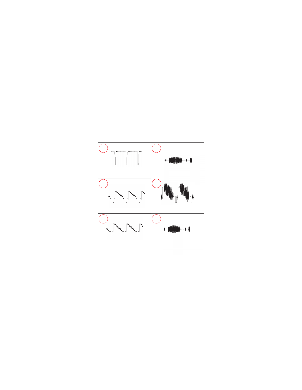
BC BOARD WAVEFORMS
21
KV-40XBR700
5.0 Vp-p (H)
3
1.0Vp-p (H)
5 6
2.5 Vp-p (H) 0.98 Vp-p (H)
4
0.54 Vp-p (H)
2.3 Vp-p (H)
— 77 —
Page 77

C BOARD SCHEMATIC DIAGRAM
1 | 2 | 3 | 4 | 5 | 6 | 7 | 8 | 9 | 10 | 11 | 12 |
A
—
B
—
C
—
D
1
9
8
0
9
R
C
k
0
1
0
N
R
:
F
4
0
9
C
3
0
0
9
V
R
M
5
(
W
J
0
9
R
2
.
C
N
9
1
B
:
S
M
-
R
E
W
O
P
B
A
O
T
C
2
0
1
0
R
:
P
0
L
K
I
R
G
B
-
O
N
1
C
R
O
1
V
R
D
E
2
3
V
R
D
E
4
5
V
R
D
E
6
7
V
2
1
8
K
I
9
E
1
0
E
T
U
M
D
R
A
2
0
2
0
1
)
M
6
1
1
9
k
N
2
3
L
K
-
L
B
3
1
0
9
7
4
0
.
P
I
H
C
:
6
0
V
2
0
7
0
9
R
0
3
3
R
0
9
R
3
3
G
9
R
3
B
0
0
Q
9
0
D
6
S
2
V
2
4
0
3
0
Q
9
A
1
6
0
D
S
2
A
1
M
B
7
0
0
3
T
M
-
L
K
L
B
T
1
0
9
R
4
1
0
9
R
0
2
2
R
:
0
9
0
9
Q
9
A
0
7
S
B
R
E
F
F
U
1
2
7
0
0
2
2
4
0
9
R
3
7
0
9
k
1
k
1
P
I
H
C
I
H
C
:
1
0
0
Q
9
A
0
9
7
B
S
2
R
E
F
U
F
B
—
R
:
V
2
E
—
F
1
C
N
9
0
0
4
1
P
1
E
T
R
C
O
T
C
H
C
—
6
0
0
9
G
—
R
k
0
1
5
6
0
9
R
4
0
0
9
Q
9
0
7
B
2
S
F
B
U
-
I
K
3
1
0
9
R
k
7
.
k
1
P
I
H
C
:
1
8
0
0
9
R
A
k
3
3
F
P
I
H
C
:
2
1
0
9
R
k
1
8
6
0
9
R
k
0
5
1
P
I
H
C
:
2
0
9
0
D
1
9
0
3
M
A
T
C
T
E
O
R
P
H
C BOARD WAVEFORMS
2.4 Vp-p (H)
KV-40XBR700
G
4
0
2
C
N
0
9
4
P
W
H
2
0
0
9
L
N
)
M
M
5
(
W
5
0
0
Q
9
A
1
6
0
D
S
2
T
M
-
L
K
L
B
1
0
0
9
0
1
0
C
9
5
6
1
0
9
R
0
2
2
8
P
R
:
1
1
9
0
Q
A
0
9
7
B
2
S
E
R
F
U
F
B
9
1
0
9
k
9
.
3
P
I
H
C
0
1
0
9
p
4
P
I
H
C
:
2
4
0
9
C
0
3
3
V
5
2
8
0
0
9
C
9
4
0
9
k
1
p
5
P
I
H
C
P
I
H
C
:
H
C
1
3
0
9
R
k
2
P
C
-
N
R
:
5
1
0
9
C
1
0
0
9
R
p
4
k
5
1
P
I
H
C
:
H
C
P
I
H
C
:
7
0
0
9
C
p
1
P
I
H
C
:
H
C
7
0
0
9
R
k
2
P
C
-
N
R
:
R
:
V
2
1
9
1
0
9
C
7
4
0
.
0
P
I
H
C
:
F
R
V
2
1
6
2
0
9
R
k
2
P
C
-
N
R
:
6
0
0
9
C
p
1
P
I
H
C
:
H
C
9
0
0
9
C
8
1
0
9
p
4
k
7
.
4
P
I
H
P
C
:
H
C
I
H
C
+12V
B
21
1 2 3 4 5 6 7 8
V
2
1
2
2
0
9
C
1
0
.
0
F
V
0
0
2
3
2
0
9
C
1
0
.
0
F
G
1
2
0
9
C
0
1
V
0
5
2
T
H
:
5
0
9
0
D
1
1
A
1
M
M
P
U
-
D
S
A
B
I
9
R
1
:
V
0
0
2
4
3
0
9
R
k
6
.
5
N
R
:
3
2.1 Vp-p (H)
I
1
6
A
T
D
V
I
-
E
D
R
12VVIVB
E
2
1
0
9
C
7
4
0
0
.
0
V
0
0
5
E
3
0
9
R
C
1k:
5
3
0
9
R
k
2
.
2
P
C
-
N
R
:
VB
V
2
1
0
9
C
0
.
0
C
:
F
5
2
0
9
C
3
3
0
0
2
2
k
2
V
6
1
N
R
T
H
:
2
0
9
C
0
.
0
F
V
2
1
2.0 Vp-p (H)
4
N
Q
/
1
1
U
T
O
-
E
O
D
IK
6
P
I
H
9
C
C
:
H
C
VB
1 2 3 4 5 6 7 8
0
V
0
2
R
6
2
7
4
R
:
P
I
H
VB
1 2 3 4 5 6 7 8
7
1
4
2
0
9
C
7
4
0
.
0
P
I
H
C
:
F
R
4
200VVFVO
)
M
4
M
0
5
9
(
R
W
J
0
9
C
0
0
.
0
H
C
:
B
5
0
0
p
4
P
I
H
T
E
E
R
G
12VVIE
8
3
0
9
k
2
.
2
P
C
-
N
12VVIE
3
0
9
R
2
.
2
C
-
N
R
:
T
U
O
.
D
E
VOF
9
S
H
R
P
8
2
7
4
P
I
C
7
3
0
9
R
0
0
1
W
3
S
R
:
2
0
9
0
C
I
N
4
/
1
Q
1
6
1
A
D
T
O
U
-
E
O
D
I
-
V
N
IK
1
1
0
9
C
7
4
0
0
.
0
V
0
0
5
E
1
4
0
9
R
k
1
P
I
H
C
:
3
0
0
9
C
p
4
P
I
H
C
:
H
C
IK
4
1
0
9
C
7
4
0
0
.
0
V
0
0
5
E
2
4
0
9
R
k
1
P
I
H
C
:
2
0
0
9
C
p
4
P
I
H
C
:
H
C
9
k
P
4 5 6
9
V
R
1
1
/
1
7
4
0
9
R
0
2
2
W
2
/
1
0
5
0
9
R
C
R
:
k
9
.
3
6
0
0
9
D
D
3
T
8
S
T
E
C
T
O
2
0
0
9
L
6
0
6
0
L
E
:
8
1
0
9
0
1
V
0
5
2
T
H
:
U
O
.
N
E
E
R
G
5
200VVFVO
)
5
M
4
M
0
5
9
(
R
W
J
9
2
0
9
C
7
4
0
0
.
0
P
I
H
C
:
B
3
4
0
9
R
0
0
1
W
3
S
R
:
U
O
.
E
U
L
B
6
200VVFVO
)
6
M
4
M
0
5
9
(
R
W
J
0
3
0
9
C
7
4
0
0
.
0
P
I
H
C
:
B
4
4
0
9
R
:
W
3
0
0
1
2
0
2
0
9
C
0
1
V
0
5
2
T
H
:
135.0 Vp-p (H) 114.1 Vp-p (H) 123.1 Vp-p (H)
J
2
C
1
V
3
1
1
0
0
M
0
W
2
3
-
1
G
1
1
T
S
H
R
0
2
0
1
T
VOF
1
5
0
9
R
0
2
2
9
W
2
/
1
C
R
:
7
0
0
9
D
D
3
T
8
S
S
H
T
E
C
T
R
O
P
T
3
0
0
C
9
I
4
N
Q
/
1
1
1
6
A
T
D
U
O
-
E
O
D
V
I
-
U
E
L
B
VOF
9
2
5
0
9
R
0
2
2
W
2
/
1
C
R
:
8
0
0
9
D
T
3
8
S
S
H
C
T
E
O
P
R
S
R
V
0
0
3
2
4
G
1
2
E
:
T
D
T
G
2
3
1
3
1
R
K
0
1
4
5
-
1
1
G
6
5
7
H
1
H
2
8
6
9
-
1
2
G
7
2
0
1
1
1
B
K
8
K
G
9
4
0
0
9
C
7
4
0
0
.
0
V
k
2
E
0
1
0
D
9
0
-
1
J
T
Z
M
G
R
E
-
G
1
7
5
0
9
R
k
0
6
5
W
2
/
1
C
R
:
V
G
V
3
5
0
9
R
k
9
.
3
3
0
0
9
L
6
0
6
0
L
4
5
0
9
R
k
9
.
3
4
0
0
9
L
0
6
0
L
E
:
3
1
0
D
9
3
1
3
S
1
S
P
M
U
-
D
2
G
9
R
.
6
6
3
0
9
C
0
1
3
0
9
C
2
.
B
6
2
6
5
0
9
R
0
0
1
W
2
/
1
C
R
:
1
6
0
9
R
3
3
0
9
C
0
0
1
2
2
W
2
/
1
V
0
5
2
C
R
:
9
0
9
0
D
D
8
P
0
G
T
E
E
S
R
1
-
D
9
5
0
9
R
k
1
W
2
/
1
C
R
:
5
3
0
9
C
0
0
1
7
7
0
9
R
V
6
1
k
1
4
1
9
0
D
3
3
1
S
1
S
T
C
T
E
O
P
R
5
1
9
0
D
8
0
9
0
Q
S
C
2
G
2
8
7
0
k
8
7
3
1
S
S
1
A
1
3
1
3
E
C
T
O
P
R
F
R
E
-
6
0
1
9
D
3
3
1
S
S
1
T
E
C
T
O
P
R
8
0
9
R
9
7
0
9
R
k
6
3
.
5
.
3
0
9
C
.
4
6
1
0
9
C
)
m
m
5
.
7
(
W
J
1
3
0
9
C
p
0
8
6
V
k
2
B
2
6
0
8
0
9
R
9
R
k
0
8
1
k
0
0
1
1
W
2
/
1
W
2
/
2
3
6
0
9
R
k
0
0
1
W
2
/
1
9
R
1
4
0
9
Q
S
2
G
3
S
2
T
G
P
1
V
R
k
8
3
7
1
0
0
9
L
N
)
M
M
5
(
W
J
C
R
G
R
.
3
3
2
6
4
C
/
1
F
E
-
R
2
9
R
2
1
9
0
Q
.
3
/
1
A
1
1
3
3
C
F
R
E
-
2
7
1
9
0
D
3
3
1
S
1
S
C
T
E
O
T
R
2
0
0
9
k
0
0
1
3
8
0
9
R
k
9
3
9
0
0
9
R
k
0
1
9
6
0
9
R
)
M
M
5
1
(
W
J
E
RIV
D
T
E
V
I
R
D
B
J
1
0
0
9
L
2
3
0
9
C
8
6
2
4
R
V
0
0
7
6
0
M
3
W
2
6
7
0
M
3
W
2
0
9
C
.
0
C
:
B
)
m
m
5
(
W
J
p
0
V
k
B
4
6
0
9
k
0
8
1
W
2
/
1
D
9
1
S
O
R
P
7
4
1
0
P
I
H
0
1
0
9
R
k
0
1
6
0
0
9
L
5
8
0
9
R
8
0
L
H
L
:
k
0
8
1
W
2
/
1
5
5
0
9
R
k
0
8
1
W
2
/
1
5
0
0
9
L
0
1
L
H
L
:
1
0
0
3
3
1
S
T
C
E
T
4
0
0
9
R
k
2
.
8
3
0
0
9
D
3
3
1
S
1
S
T
C
E
T
O
P
R
1
0
0
9
C
0
3
3
V
5
2
5
0
0
9
R
k
2
.
2
2
0
0
Q
9
A
1
3
1
3
C
2
S
E
U
T
M
C
-
9
1
-
9
A
1
X
D
T
M
:
I
N
I
(
L
C
O
K
)
2
1
G
V
0
0
2
2
E
3
1
H
4
D
R
A
O
B
D
O
T
3
0
0
N
5
C
C BOARD TRANSISTOR VOLTAGE LIST
BCE
Q9001 7.5 0.0 3.6
Q9002 0.2 11.1 GND
Q9003 2.1 12.0 4.0
Q9004 2.1 12.0 3.2
Q9005 3.2 12.0 2.1
Q9008 5.4 12.0 4.8
Q9009 4.0 GND 4.6
Q9010 3.2 GND 4.0
Q9011 4.7 GND 3.9
Q9012 5.4 10.5 4.8
0
3
0
C
N
9
1
P
E
1
T
R
C
O
T
I
C
2
3
Q9014 11.7 450.0 11.1
All voltages are in V.
C BOARD IC VOLTAGE LIST
IC9001 IC9002 IC9003
PIN VOLT PIN VOLT PIN VOLT
1 3.5 1 3.5 1 3.5
2 12.0 2 12.0 2 12.0
3 3.5 3 3.5 3 3.5
4 GND 4 GND 4 GND
5 8.7 5 8.6 5 7.8
6 198.5 6 198.5 6 198.5
7 17.9 7 115.0 7 147.0
8 150.0 8 154.0 8 150.0
9 118.2 9 114.0 9 115.0
All voltages are in V.
— 78 —
Page 78

C
[CRT DRIVE, RGB DRIVE]
COMPONENT SIDE
KV-40XBR700
1
C
N
9
0
0
1
0
0
9
P
L
C
4
3
0
9
A
R
4
4
0
9
C
B
6
9
3
0
9
3
3
0
9
R
C
B
1
2
0
0
0
0
9
9
W
W
J
J
1
2
2
0
9
C
7
3
0
9
R
0
4
0
9
R
9
7
4
0
9
R
C
L
R
V
9
0
0
1
H
S
T
N
D
1
0
0
9
L
N
6
1
0
9
C
E
C
L
9
6
0
9
R
E
E
2
1
1
1
0
9
R
E
N
C
9
0
0
5
P
9
0
0
2
C
N
9
0
23456
T
-
U
R
E
M
E
P
W
V
V
V
R
R
6
1
1
0
1
3
0
0
9
V
R
9
0
9
R
5
2
4
1
0
9
Y
E
0
9
C
1
0
0
9
2
C
I
2
1
0
9
C
8
6
0
0
9
D
5
1
0
9
Y
E
3
0
0
9
0
0
9
C
C
0
3
9
4
0
8
1
7
0
0
0
9
9
9
R
R
6
4
0
9
C
3
0
0
9
W
J
J
8
1
0
9
C
3
4
0
9
R
0
2
5
0
0
0
9
9
R
L
4
E
1
J
9
0
0
1
1
-
A
E
N
9
0
0
4
R
5
0
4
0
0
9
W
J
0
9
W
J
9
0
0
9
W
3
2
0
9
C
5
4
0
9
R
1
5
0
9
R
3
5
0
9
R
E
K
R
0
9
Y
3
0
0
9
L
-
2
3
3
E
G
1
-
3
0
A
-
5
7
5
-
1
6
8
-
7
1
7
1
8
6
7
7
9
8
1
0
R
0
9
9
R
6
8
0
R
5
1
0
9
9
R
R
6
0
0
9
W
J
2
1
0
9
Y
E
1
2
0
0
9
2
C
I
1
1
0
9
C
7
0
0
9
W
J
0
1
0
9
W
J
1
1
0
9
W
J
1
2
0
9
C
4
4
0
9
R
8
9
7
0
0
9
D
3
1
0
9
Y
9
0
K
G
1
0
0
9
Y
E
E
2
8
-
2
1
1
2
3
8
1
4
4
5
0
0
0
9
9
R
L
K
B
0
0
9
Y
E
G
G
2
6
5
0
9
R
R
D
D
D
E
E
R
G
B
C
N
2
7
0
9
R
8
0
0
9
W
J
7
2
0
9
C
6
4
0
9
R
2
5
0
9
R
0
3
0
9
R
3
3
0
9
C
7
1
-
2
H
2
5
0
0
9
Y
E
W
J
H
1
G
1
-
1
3
0
0
9
Y
E
1
3
0
9
C
2
6
0
9
R
O
2
K
1
E
1
0
8
3
0
9
C
E
I
+
9
0
0
1
2
6
9
0
0
9
R
1
0
0
8
8
0
9
R
2
4
0
9
C
0
9
9
R
R
9
R
5
6
0
0
1
0
9
Y
E
2
1
0
9
W
J
1
3
0
0
9
2
C
I
6
3
0
9
C
4
1
0
0
2
0
9
C
9
C
8
9
D
0
1
0
9
D
0
9
R
6
1
0
9
2
3
0
9
C
9
L
4
6
0
9
R
4
8
0
9
R
3
1
0
9
8
0
0
9
D
1
1
0
9
Y
E
7
5
0
9
R
9
0
0
9
D
1
6
9
5
0
9
R
2
1
0
0
0
0
9
9
7
L
L
1
N
0
9
W
J
0
5
0
5
8
0
9
R
7
6
0
9
R
R
V
-
2
G
C
L
P
9
0
0
3
8
0
9
R
0
9
V
R
B
5
2
0
0
0
0
9
9
R
Q
E
8
7
0
9
R
4
1
0
9
D
8
0
0
9
Q
B
3
1
0
9
W
J
4
3
1
0
0
0
0
0
0
9
9
9
R
D
D
5
3
0
9
C
7
7
0
9
R
1
H
E
0
0
2
V
2
G
5
5
0
9
R
3
6
0
9
R
0
9
R
4
2
0
0
1
0
9
R
0
9
0
9
R
B
5
1
0
9
D
1
8
0
9
R
4
1
0
9
W
J
2
1
0
9
Q
B
E
E
6
7
1
1
0
0
9
9
D
D
7
3
0
9
C
5
9
1
7
0
0
9
9
W
R
E
J
1
0
0
9
C
E
4
1
0
9
Q
B
6
0
0
9
L
4
2
0
0
9
N
C
1
L
P
9
0
0
3
C
6
7
C BOARD LOCATOR LIST (COMPONENT SIDE)
DIODE
D9001 B-6 D9017 B-6
D9003 B-6
D9007 C-3 IC9001 B-2
D9008 C-5 IC9002 B-3
D9009 D-5 IC9003 B-5
D9010 C-5
D9013 C-5 Q9002 A-5
D9014 B-6 Q9014 C-6
D9015 A-6
D9016 B-6
IC
TRANSISTOR
— 79 —
Page 79

|
C
[CRT DRIVE, RGB DRIVE]
CONDUCTOR SIDE
1 | 2 | 3 | 4 | 5 | 6
G
2
-
V
R
9
2
V
0
R
0
0
0
5
R
9
R
9
0
1
A
—
B
0
D
9
0
1
5
R
9
0
8
1
E
2
1
0
9
Q
R
E
B
B
D
9
0
8
0
9
Q
—
1
C
9
0
0
0
4
7
C
9
C
—
L
9
0
0
6
D
H
1
—
E
—
E
G
R
3
R
9
0
6
R
9
0
7
6
F
KV-40XBR700
C
N
9
0
0
C
9
0
1
0
1
C
9
0
3
8
0
0
9
R
9
R
9
0
6
5
R
9
9
0
7
8
4
0
1
C
R
L
2
9
0
5
5
N
9
C
0
1
0
0
9
Q
0
0
6
R
9
0
1
3
I
C
9
0
0
3
9
0
2
0
0
0
8
D
9
9
0
5
7
9
D
9
0
0
R
9
0
6
1
0
2
V
0
5
9
0
0
R
9
0
8
5
R
9
R
9
0
6
7
9
Q
1
0
0
1
R
9
0
7
2
R
9
0
8
8
D
9
0
0
2
C
9
0
0
C
9
C
9
0
3
0
R
9
0
3
0
D
9
0
1
0
C
9
0
3
3
R
9
0
6
4
0
8
4
R
9
0
6
2
3
1
1
Q
1
0
9
Q
R
9
0
4
R
9
0
7
R
9
0
0
0
2
0
5
2
R
9
H
1
H
8
4
9
5
0
0
9
Q
0
0
2
I
9
C
R
9
0
6
8
3
9
C
9
0
2
1
0
0
D
9
K
G
B
K
1
G
2
-
2
1
G
1
-
2
G
1
K
2
E
8
1
7
1
8
6
8
5
6
8
-
7
-
3
0
0
9
Q
4
0
0
9
0
R
9
0
3
8
C
9
0
0
3
R
9
0
4
1
C
9
0
2
9
7
0
R
9
R
9
L
9
G
-
1
3
R
2
1
3
-
1
1
2
6
C
9
0
4
R
V
9
0
0
I
C
9
C
9
0
1
8
5
1
0
5
3
0
0
3
0
0
9
L
N
0
0
9
C
E
1
E
E
E
C
N
9
0
0
4
6
Q
2
0
9
0
R
9
0
3
0
3
0
1
R
R
9
C
D
9
0
0
6
3
4
R
C
N
0
9
2
E
E
E
E
C
0
N
0
9
3
3
R
9
0
3
4
9
0
3
5
C
9
0
0
5
0
3
6
9
0
2
8
1
0
0
9
L
N
9
0
6
9
0
5
1
2
0
0
9
P
L
C
C BOARD LOCATOR LIST (CONDUCTOR SIDE)
DIODE
D9002 A-2 Q9005 A-3
D9005 A-5 Q9008 B-1
D9006 C-5 Q9009 A-4
TRANSISTOR
Q9001 A-2 Q9011 A-3
Q9003 A-4 Q9012 B-1
Q9004 A-4
Q9010 A-4
— 80 —
Page 80

D BOARD SCHEMATIC DIAGRAM (1 OF 3)
1 | 2 | 3 | 4 | 5 | 6 | 7 | 8 | 9 | 10 | 11 | 12 | 13 | 14 | 15 |
A
—
B
—
C
—
D
—
E
N
2
P
T
H
W
K
)
C
O
(
L
I
I
N
M
:
T
U
O
C
A
1
2
T
U
O
C
A
3
1
6
0
N
C
D
R
O
A
B
A
O
T
O
T
T
1
5
0
6
C
N
P
6
H
T
W
V
H
:
+
T
C
E
R
C
A
1
C
2
N
-
T
C
E
R
C
A
3
C
N
4
V
5
1
R
I
P
5
D
6
N
G
5
0
0
N
6
C
R
D
A
O
B
A
0
4
5
N
6
C
P
8
2
0
N
7
C
D
R
O
A
B
A
O
Y
L
R
C
A
1
Y
L
R
N
I
A
M
2
E
3
E
4
E
5
L
A
M
R
O
N
6
E
7
P
W
8
1
I
R
P
P
.
W
+
T
C
R
E
C
A
V
5
4
8
5
6
C
7
4
0
.
0
V
5
2
1
1
9
5
6
C
p
0
0
0
1
V
0
5
2
B
P
2
O
T
Y
L
R
N
A
M
I
2
5
0
6
C
—
0
5
5
6
C
N
P
F
—
G
—
T
A
O
B
A
O
T
8
V
5
Y
T
B
S
E
7
6
V
2
1
N
I
A
M
V
5
N
A
I
M
5
4
E
V
9
N
A
I
M
3
2
E
V
3
3
1
0
6
5
6
C
N
P
8
0
3
7
C
N
R
D
K
C
L
/
B
0
K
C
L
1
A
T
D
B
/
T
0
A
D
2
E
3
4
1
T
O
R
P
V
5
M
N
V
5
6
E
P
V
O
7
8
P
C
O
B
+
8
0
6
0
N
6
C
R
D
A
B
O
A
O
V
5
B
Y
T
S
V
1
2
N
I
A
M
V
9
I
N
A
M
V
3
3
K
B
L
/
C
0
K
L
C
T
B
A
/
D
0
T
A
D
V
5
M
V
N
P
V
O
B
+
P
C
O
B
+
V
5
Y
B
T
S
V
2
1
M
N
I
A
V
5
N
I
A
M
V
9
M
N
I
A
KV-40XBR700
7
V
B
U
S
6
5
1
6
+
T
C
E
R
C
1
0
5
6
R
J
0
P
I
H
C
:
6
8
5
6
C
0
3
6
5
D
7
4
0
0
.
0
0
L
6
S
B
6
D
V
0
5
2
C
T
E
-
R
C
A
5
8
5
6
C
p
0
0
0
1
V
0
5
2
B
1
0
5
6
Y
R
3
4
1
3
1
5
D
6
1
1
1
M
A
C
T
E
O
T
R
P
Y
L
R
C
A
6
1
5
6
R
3
.
3
2
W
0
1
B
R
:
2
0
5
6
Y
R
4
3
2
1
9
1
5
6
R
0
P
I
H
C
:
3
3
5
D
6
1
1
1
M
A
T
E
C
T
O
P
R
0
1
5
6
R
2
2
W
1
S
R
:
8
2
5
6
R
0
0
1
P
I
H
C
:
2
3
5
6
R
k
0
1
P
I
H
C
:
2
3
5
Q
6
A
1
0
6
S
D
2
1
-
H
C
A
T
L
V
1
5
I
R
P
F
8
8
5
6
C
7
4
0
0
.
0
V
0
5
2
F
5
6
W
J
M
5
.
7
3
2
5
D
6
8
0
-
2
2
A
E
R
R
P
E
P
O
S
T
6
R
1
F
:
P
O
1
2
5
N
k
1
R
E
I
S
S
T
W
2
/
D
R
P
1
7
0
5
6
R
k
7
.
4
P
I
H
C
:
2
V
7
B
U
S
)
-
(
W
S
-
P
Y
L
R
N
I
A
M
2
7
5
6
Q
4
1
1
2
D
2
S
9
0
5
6
R
R
D
Y
-
L
-
R
C
A
k
7
.
4
P
I
H
C
:
0
3
5
6
R
k
7
.
4
P
I
H
C
:
0
3
6
5
Q
A
0
9
7
B
2
S
2
H
-
C
T
L
A
3
5
6
R
0
1
I
H
C
:
7
3
5
6
R
6
9
5
6
C
k
0
1
1
P
I
H
C
:
7
8
5
6
C
7
4
0
0
.
0
V
0
5
2
F
9
8
5
6
C
7
4
0
0
.
0
V
0
5
2
F
4
0
5
6
W
J
3
0
M
M
5
.
7
M
1
0
6
H
5
3
7
1
1
-
R
R
O
S
H
R
O
T
4
3
V
8
k
O
-
V
0
0
2
P
1
0
5
D
6
1
1
1
M
A
5
1
5
6
R
0
9
5
6
C
0
0
2
1
V
0
5
2
R
3
0
5
6
C
0
0
2
1
V
0
5
2
V
5
1
I
R
P
U
S
P
C
7
5
3
6
D
1
1
1
A
M
9
0
6
5
D
k
0
7
4
/
1
5
6
7
4
/
1
B
E
6
S
0
4
-
0
C
E
R
W
2
0
5
1
6
D
2
0
S
E
6
0
4
-
0
R
C
E
k
0
W
2
V
7
7
2
5
6
R
0
5
5
6
R
k
8
6
k
7
.
4
P
I
H
C
:
P
I
H
C
:
O
-
P
V
C
0
0
2
6
4
6
6
R
1
5
6
R
k
0
3
3
0
3
3
N
R
:
R
:
4
0
5
6
R
k
0
1
P
I
H
C
:
6
2
5
6
R
1
.
0
2
/
1
F
R
:
6
C
1
2
2
5
5
6
R
k
2
2
W
P
I
H
C
:
7
5
5
6
R
k
0
0
1
P
I
H
C
:
2
6
5
Q
6
A
0
9
7
B
S
2
C
H
T
A
L
5
9
5
4
3
5
6
R
0
0
k
3
3
V
5
P
I
H
C
:
3
0
5
Q
6
3
1
5
6
R
4
A
1
0
6
D
S
2
k
0
3
3
k
T
R
O
P
N
R
:
N
4
0
5
6
C
1
0
.
0
P
I
H
C
:
B
P
R
8
0
5
6
R
k
0
1
P
I
H
C
:
5
6
C
7
1
5
6
R
.
0
k
2
.
8
C
:
B
P
C
-
N
R
:
1
4
5
6
R
k
5
1
P
I
H
C
:
3
4
5
6
R
k
0
3
3
P
C
-
N
R
:
3
5
5
6
R
k
0
3
3
P
I
H
C
:
7
1
5
6
C
7
.
4
7
0
5
6
C
7
4
6
1
5
6
C
1
0
0
.
0
P
I
H
C
:
B
3
0
5
6
R
0
0
1
P
C
-
N
R
:
V
5
1
I
3
2
5
6
R
k
2
2
P
I
H
C
:
4
9
5
6
C
1
.
0
V
5
2
P
I
H
C
:
B
9
5
2
6
Q
A
1
6
0
D
S
2
H
T
C
A
L
1
1
5
6
R
k
0
1
P
I
H
C
:
A
0
1
5
C
6
I
1
D
0
3
0
Z
C
M
E
R
V
R
I
D
D
E
N
S
E
S
V
V
1
1
1
1
0
P
I
H
2
8
1
5
6
C
1
0
0
.
0
P
P
:
3
8
1
5
6
R
k
5
1
P
C
-
N
R
:
4
5
9
1
5
6
C
0
1
6
7
8
9
6
0
5
6
R
7
4
.
0
D
R
P
F
:
8
2
5
6
Q
A
0
1
6
S
D
2
2
-
W
S
-
C
V
8
1
.
/
B
F
7
1
H
G
)
(
V
C
T
6
1
V
S
T
R
5
1
B
V
D
G
N
4
1
E
I
R
M
T
3
1
L
G
)
(
V
S
S
2
1
D
G
N
-
P
C
1
V
1
1
2
V
C
P
O
C
0
1
D
:
1
0
5
6
R
1
9
P
C
-
N
R
:
9
2
5
6
R
0
1
D
R
P
F
:
0
1
5
6
C
1
.
0
T
P
:
1
3
5
6
R
0
1
2
0
6
5
D
D
R
P
F
:
5
0
0
4
F
U
U
P
-
M
P
U
P
8
0
5
6
C
7
4
V
5
2
7
0
6
5
0
P
I
C
H
P
N
O
5
2
5
6
R
M
A
I
N
0
7
4
P
I
H
C
:
4
3
4
2
5
6
R
0
P
I
H
C
:
4
2
2
5
6
R
k
0
1
P
I
H
C
:
3
V
5
Y
B
T
S
V
3
3
8
0
5
6
B
F
9
0
5
6
B
F
H
U
5
4
.
0
H
U
5
4
.
0
2
0
5
6
B
F
H
U
5
4
.
7
0
5
Q
6
A
0
N
5
7
I
B
F
R
I
E
R
T
R
V
E
N
C
O
3
3
5
6
R
k
0
1
P
I
H
C
:
5
3
5
6
R
k
0
1
P
I
H
C
:
H
5
6
0
2
1
7
1
-
R
3
C
O
T
N
O
R
L
5
6
R
1
H
C
:
1
2
1
2
3
0
5
6
H
P
R
-
1
7
1
3
N
O
W
S
N
I
A
M
0
6
2
5
6
C
1
0
0
.
0
V
k
1
R
6
4
5
6
R
)
M
M
5
.
7
(
W
J
S
6
0
6
5
Q
A
5
0
N
7
I
B
F
I
R
E
R
T
E
R
V
O
N
C
5
2
5
6
C
1
0
0
.
0
V
k
1
S
R
5
4
5
6
R
)
M
M
5
.
7
(
W
J
V
5
1
+
V
5
1
+
5
1
-
2
4
k
P
I
4
4
5
6
R
0
P
I
H
C
:
0
4
5
6
R
k
1
P
I
H
C
:
)
M
A
0
8
0
(
V
5
1
-
V
R
:
)
A
M
0
3
0
(
7
4
5
6
k
5
.
1
P
I
H
C
1
5
3
6
Q
A
0
1
6
D
S
2
W
-
S
N
I
M
A
6
3
5
6
R
k
0
1
P
I
H
C
:
2
1
5
6
R
k
0
1
P
I
H
C
:
2
3
5
6
C
6
5
5
6
R
p
0
0
0
6
5
5
0
.
0
V
0
0
8
W
2
B
R
:
P
P
:
4
0
5
6
L
5
V
1
+
8
0
L
H
L
:
3
0
5
6
L
8
0
L
H
L
:
+
6
4
5
6
C
0
0
7
4
V
5
2
5
4
5
6
C
0
0
2
2
V
5
2
9
8
7
6
4
3
2
1
1
6
5
D
-
6
S
S
B
4
D
E
R
V
5
1
0
2
5
6
B
F
)
M
M
5
(
W
J
1
2
5
6
B
F
)
M
M
5
(
W
J
1
0
5
6
T
T
I
P
:
0
1
4
0
5
6
B
F
H
U
1
.
1
1
1
2
1
3
1
0
5
6
B
F
H
U
1
.
1
4
1
6
B
F
0
5
1
6
1
7
1
8
1
4
F
T
C
3
8
5
6
R
k
5
1
P
I
H
C
:
U
S
R
E
W
O
P
T
C
E
R
C
A
V
3
3
D
F
6
-
S
S
B
4
D
T
C
R
E
U
A
-
+
6
0
5
6
B
F
H
U
0
0
2
1
3
5
D
6
1
0
F
4
L
C
8
D
T
E
C
R
V
5
1
3
5
0
5
H
U
5
0
6
I
C
5
-
D
M
O
T
R
N
O
C
453
1
5
5
6
C
2
2
0
.
0
P
I
H
C
:
B
Y
L
P
P
2
0
5
6
S
P
0
7
N
P
C
I
8
4
5
6
C
1
0
5
6
S
P
0
0
3
3
0
7
N
P
C
I
V
5
3
5
1
5
D
6
7
4
5
6
C
F
6
0
L
S
2
0
2
2
T
C
E
-
R
V
0
V
0
5
2
4
4
5
6
C
3
3
0
6
1
0
2
3
8
L
5
0
5
6
L
0
V
0
1
L
H
L
:
7
1
5
D
6
F
6
0
L
S
2
T
C
E
-
R
V
0
1
0
9
5
6
R
0
8
6
D
R
P
F
:
4
2
+
U
A
D
R
G
U
A
V
0
2
0
V
5
3
1
1
9
5
6
R
2
2
.
0
W
1
S
R
:
6
Q
A
1
S
2
+
B
5
D
6
1
M
A
7
9
5
6
R
k
0
0
1
I
B
N
R
:
6
9
5
6
R
k
0
1
6
R
1
N
R
:
:
1
+
3
9
5
6
R
0
0
1
D
R
P
F
:
5
6
C
I
4
-
1
E
S
O
B
+
9
3
5
6
R
k
2
2
W
2
S
R
:
V
4
2
O
I
D
U
A
V
0
2
V
0
V
5
3
1
8
9
5
6
R
7
2
.
0
W
1
S
R
:
0
2
5
S
0
8
2
P
O
C
R
2
2
1
1
S
A
0
0
6
k
0
N
R
V
5
0
6
6
R
k
1
I
H
C
:
1
5
0
0
N
P
V
3
+
3
0
6
5
N
V
5
Y
B
T
S
4
0
6
6
R
k
0
1
P
I
H
C
:
R
9
9
5
6
:
k
1
1
6
5
6
C
1
2
P
2
3
V
3
8
0
5
D
6
C
3
-
3
J
Z
M
T
P
V
O
B
+
4
2
6
5
Q
9
A
0
1
3
A
2
S
H
T
C
A
L
P
C
O
3
0
6
6
k
0
1
C
2
C
O
P
C
O
B
+
P
I
H
2
1
6
6
R
k
7
4
P
I
H
C
:
1
2
6
5
Q
1
A
1
3
3
C
S
H
T
C
A
L
P
5
0
6
6
R
k
2
.
2
P
I
H
C
:
2
5
2
6
Q
A
0
9
3
A
1
S
2
S
W
V
P
O
P
C
O
B
+
4
1
6
6
R
3
.
3
W
2
/
1
D
R
P
F
:
U
V
7
B
S
9
-
A
1
X
D
C
P
8
T
H
W
O
R
I
C
M
S
-
:
O
T
8
U
A
U
A
7
6
U
A
U
A
5
D
U
A
4
E
S
3
2
U
S
-
P
1
-
D
9
1
3
0
7
0
N
C
D
R
O
A
B
A
4
V
2
O
I
D
4
V
2
O
I
D
N
D
G
O
I
D
N
D
G
O
I
D
T
O
R
P
-
O
I
N
O
T
V
7
B
)
-
(
W
S
— 81 —
Page 81

D BOARD SCHEMATIC DIAGRAM (2 OF 3)
1 | 2 | 3 | 4 | 5 | 6 | 7 | 8 | 9 | 10 | 11 | 12 | 13 | 14 | 15 | 16 | 17 | 18 | 19 | 20 | 21 | 22 |
3
P
O
T
B
L
A
V
R
D
D
A
—
F
W
F
S
D
R
A
A
P
F
D
S
L
-
C
P
F
A
1
3
/
P
P
T
O
V
5
1
+
V
1
5
+
3
B
—
C
—
D
KV-40XBR700
5
0
6
5
C
1
S
P
M
3
0
5
0
C
I
2
1
F
2
R
1
Q
V
5
1
+
V
5
1
+
.
W
P
V
5
N
M
V
T
A
D
0
B
T
/
A
D
K
L
C
B
/
0
K
L
C
9
0
5
5
R
0
0
1
P
I
H
C
:
1
0
5
C
5
I
A
)
(
T
N
6
M
4
-
0
4
C
2
M
V
M
N
1
2
3
4
3
0
5
5
R
7
4
P
I
H
C
:
7
0
5
5
R
7
4
P
I
H
C
:
0
5
5
C
1
0
.
0
I
H
C
:
F
8
7
6
5
8
0
0
5
C
0
3
3
V
5
2
8
P
1
1
5
5
C
0
0
1
V
6
1
7
5
0
5
D
3
1
5
A
M
T
O
P
R
3
4
0
5
C
0
0
0
1
V
6
1
5
0
5
5
D
3
5
A
1
M
O
T
R
P
P
G
E
R
V
1
2
I
O
1
0
5
A
B
1 2 3 4 5
2
0
0
5
L
0
1
L
H
L
:
5
C
2
C
0
0
1
6
1
5
C
I
2
W
1
1
5
V
9
/
5
V
2
0
1
7
4
V
5
G
9
0
2
5
D
1
1
1
A
M
8
3
0
5
C
7
4
V
6
1
V
2
1
N
I
A
M
5
0
V
8
0
0
5
V
-
S
T
E
G
R
-
V
2
1
N
I
A
M
2
5
0
5
C
1
.
0
P
I
H
C
:
B
1
2
1
5
R
0
2
1
5
R
k
0
1
k
1
P
I
H
C
:
P
I
H
C
:
1
2
0
5
D
1
1
1
A
M
2
2
1
5
R
k
0
1
P
I
H
C
:
V
5
N
I
A
M
2
1
V
N
I
A
M
3
2
6
5
R
k
2
.
2
P
I
H
C
:
8
8
5
5
C
1
0
.
0
7
8
5
5
C
S
P
M
:
5
4
6
5
R
7
4
0
.
0
k
7
4
P
I
H
C
:
B
1
P
O
T
A
N
M
I
A
M
I
I
A
M
P
I
H
C
:
Y
L
R
0
5
6
5
R
k
7
4
V
9
N
P
I
H
C
:
V
5
N
6
9
5
5
C
1
A
H
2
1
3
S
W
1
1
W
0
S
4
6
6
6
5
R
k
6
5
P
I
H
C
:
1
0
5
R
C
:
5
R
C
:
1
5
R
E
I
1
A
V
6
1
7
G
V
1
4
9
5
5
C
S
A
H
8
1
.
0
1
S
P
M
:
9
I
H
1
R
D
A
0
2
1
I
V
2
1
0
5
0
2
2
P
I
H
1
1
4
1
5
0
P
I
H
P
H
-
2
2
C
2
7
6
5
R
C
-
P
D
Q
k
0
3
3
P
I
H
C
:
1
C
A
D
C
G
C
0
A
D
M
P
W
T
L
T
I
-
H
F
N
D
G
C
G
2
R
A
A
P
E
N
C
V
C
W
2
1
1
R
A
A
P
N
A
0
A
R
P
S
L
S
C
N
D
A
S
A
R
A
1
5
1
5
I
C
S
A
2
6
0
2
X
A
R
L
E
L
O
T
R
N
O
4
8
6
5
R
k
7
.
4
C
-
N
R
:
1
1
0
1
9
C
8
7
6
5
4
3
2
1
0
5
5
C
0
1
7
4
6
5
R
0
0
1
P
P
C
-
N
R
:
0
1
6
5
6
9
6
5
R
0
7
4
k
2
.
8
V
6
1
P
C
-
N
R
:
4
1
6
5
C
0
1
0
9
6
5
R
7
4
P
I
H
C
:
6
0
5
5
R
9
8
6
5
R
7
4
k
0
1
P
P
I
H
C
:
I
H
C
:
5
5
1
5
5
C
I
0
1
9
0
-
9
K
3
T
S
P
M
A
V
O
N
C
1 2 3 4 5 6 7 8
2
1
7
5
R
7
4
.
0
W
2
/
1
D
R
P
F
:
1
1
7
5
R
7
4
.
0
W
2
/
1
D
R
P
F
:
6
7
5
5
C
0
2
2
V
5
2
:
8
9
6
5
R
2
1
6
5
C
0
2
5
2
5
7
0
7
5
R
7
4
P
I
H
C
:
3
1
6
5
C
3
3
0
.
T
U
P
T
U
O
E
T
U
M
B
U
S
9
7
1
7
5
R
8
6
H
C
:
5
5
C
2
2
6
5
R
k
1
P
I
2
:
7
7
0
2
6
5
R
V
5
.
0
3
R
:
6
8
6
5
R
0
8
6
P
C
-
N
R
:
5
8
6
5
R
k
5
.
1
P
C
-
N
R
:
0
9
5
5
C
I
H
C
:
p
0
3
3
9
4
0
0
W
S
R
8
4
7
4
W
S
7
5
6
5
R
k
7
.
4
P
C
-
N
R
:
0
P
I
H
C
:
B
1
D
N
G
_
A
7
0
6
5
C
3
3
0
.
0
P
I
H
C
:
B
7
.
4
R
4
R
:
R
P
1
R
:
3
0
6
5
C
7
4
0
0
.
0
P
I
H
C
:
B
2
N
I
S
_
V
3
W
A
S
_
V
4
C
N
5
4
9
6
5
R
C
-
N
R
:
k
3
9
6
5
k
7
.
P
C
-
N
2
9
6
5
k
5
.
P
C
-
N
9
9
6
5
R
k
2
2
P
I
H
C
:
O
T
-
U
V
.
F
E
R
P
F
E
R
6
V
N
O
Y
C
H
D
-
_
-
H
7
V
N
O
Y
C
V
D
-
_
H
-
8
T
A
T
S
_
H
9
T
T
V
S
A
_
1
5
5
I
C
7
0
0
A
8
X
C
V
.
N
O
-
C
Y
D
D
2
-
1
J
T
Z
M
T
O
R
P
5
5
D
-
J
Z
M
D
N
G
_
D
8
1
L
C
S
7
1
L
D
S
6
1
C
C
V
_
D
5
1
I
-
N
D
H
4
1
-
N
V
I
.
3
1
C
_
S
W
A
2
1
C
_
C
G
A
1
1
C
C
A
V
_
0
1
3
P
A
T
O
N
C
T
O
R
P
9
1
6
5
C
p
0
7
2
P
I
H
C
:
H
C
8
1
6
5
C
3
3
.
0
S
P
M
:
9
0
7
5
R
3
2
7
4
2
1
P
I
H
C
:
T
4
1
7
5
R
k
0
0
1
P
I
H
C
:
W
1
0
7
2
8
0
7
5
R
1
2
6
5
C
1
.
0
S
P
M
:
H
C
M
6
5
C
0
1
6
1
V
5
N
I
A
M
6
1
7
5
R
5
1
7
5
R
k
1
k
0
0
1
P
I
H
C
:
P
I
H
C
:
1
0
6
5
L
6
0
6
0
L
E
:
S
R
:
8
2
6
5
5
C
2
6
5
C
0
0
1
p
0
0
1
V
6
1
P
I
H
C
:
V
1
2
N
I
A
3
2
0
V
0
1
5
5
C
I
A
F
0
-
0
6
5
A
L
T
U
-
O
S
N
E
E
1 2 3 4 5
9
7
6
5
R
5
1
D
R
P
F
:
8
7
6
5
R
k
2
.
8
P
C
-
N
R
:
V
0
7
6
5
R
k
9
3
P
C
-
N
R
:
9
6
6
5
R
k
2
P
C
-
N
R
:
2
9
5
5
C
1
.
0
P
I
H
C
:
B
1
C
C
V
1
0
6
5
C
1
.
0
S
P
M
:
8
6
5
R
.
1
R
P
F
:
0
6
5
C
7
4
V
6
1
C
F
2
0
6
5
C
7
4
V
6
1
8
8
6
5
R
0
k
1
5
P
C
-
N
R
:
D
0
k
2
.
6
P
C
-
N
R
:
1
1
6
5
1
.
0
V
5
2
P
I
H
C
:
R
:
7
9
6
5
R
0
8
1
P
C
-
N
R
:
5
R
1
R
:
V
2
1
-
C
I
5
6
L
A
I
P
V
-
1 2 3 4 5
5
1
6
5
5
1
D
R
P
F
0
0
7
k
5
P
C
-
N
4
1
5
5
F
A
-
0
0
U
T
O
-
N
E
C
E
C
V
V
2
0
7
5
R
k
1
P
C
-
N
R
:
4
0
7
5
R
1
N
R
:
3
1
7
5
R
5
0
7
5
R
0
7
4
1
W
1
N
R
:
S
R
:
6
1
6
5
C
7
1
6
5
C
1
1
.
0
7
4
S
P
M
:
V
6
1
2
3
+
Y
C
C
N
-
Y
C
0
1
5
5
N
C
P
3
T
W
H
R
O
C
M
I
-
S
:
Y
D
O
T
—
E
—
F
—
G
—
H
—
I
—
J
—
K
—
L
—
M
—
N
—
O
—
P
V
5
3
1
N
I
P
M
O
H
C
D
R
O
A
B
A
O
T
6
7
C
0
N
1
0
5
5
N
C
P
8
P
B
F
V
1
E
2
N
I
P
H
3
3
2
1
5
R
P
C
S
4
X
D
R
O
F
V
H
E
T
N
I
B
K
L
C
/
S
1
L
K
C
T
A
D
/
S
1
A
T
D
6
0
5
5
N
C
1
P
1
B
O
-
T
-
:
B
G
I
J
O
R
F
E
N
W
O
D
D
L
O
H
C
N
C
N
P
C
S
R
B
E
T
N
I
B
T
A
D
S
/
T
1
A
D
K
C
L
S
1
/
K
C
L
3
0
5
5
N
C
P
1
0
S
L
B
A
M
I
T
V
+
R
V
D
V
-
R
V
D
V
S
/
N
N
I
P
V
V
D
R
W
E
E
A
R
A
P
F
D
N
I
P
M
D
A
R
O
B
A
T
O
1
0
N
2
C
5
5
0
5
C
N
0
P
1
T
E
N
C
H
V
R
D
H
E
N
I
P
M
O
C
N
I
P
M
O
C
E
T
R
O
P
V
T
R
O
P
H
R
B
D
R
A
B
O
A
O
T
3
2
0
N
C
0
H
C
:
5
6
7
8
1
2
3
4
5
6
7
8
9
0
1
1
1
1
4
1
2
3
4
5
6
7
8
9
0
1
1
2
3
3
1
4
5
6
7
8
9
0
1
4
2
1
5
R
0
P
I
P
I
H
C
:
K
L
C
S
D
T
A
S
N
W
O
D
D
L
O
H
0
1
5
5
R
0
0
1
P
I
H
C
:
8
0
5
5
R
0
0
1
P
I
H
C
:
5
1
V
5
1
-
R
:
R
:
4
0
5
C
1
.
0
I
H
C
:
F
V
5
1
+
2
0
5
0
C
4
2
5
V
1
5
-
5
0
0
5
Q
A
0
1
6
S
D
2
R
E
F
U
F
B
5
0
2
0
5
R
k
6
.
5
P
C
-
N
R
:
5
2
0
5
R
k
6
.
5
P
C
-
N
R
:
5
R
1
C
:
R
1
9
9
5
k
0
P
I
H
C
4
2
5
D
-
J
Z
T
M
9
1
0
k
0
L
C
1
8
0
5
C
1
5
R
3
.
3
2
2
0
.
0
-
N
R
:
T
P
:
0
8
0
5
C
2
2
0
.
0
T
P
:
0
0
7
5
0
0
0
7
V
5
0
0
5
M
A
1
3
k
P
C
P
I
H
C
:
V
9
3
2
0
5
R
k
7
.
4
P
I
H
C
:
1
B
1
.
4
0
5
R
P
5
.
1
R
P
F
:
7
4
1
5
R
k
3
.
3
P
C
-
N
R
:
0
0
5
I
C
7
9
3
V
T
S
U
O
V
-
Vcc
6
7
F.B.-PLS
V-DRV-
1234567
6
1
0
5
C
1
3
3
.
0
S
P
M
:
D
9
2
0
5
R
k
7
.
4
P
C
-
N
R
:
1
0
0
5
H
T
0
1
0
5
R
J
7
0
0
5
D
3
2
G
K
P
8
D
0
P
G
U
P
-
M
P
U
P
4
9
T
5
Vee
Vcc(OUT)
V-DRV+
OUT-PUT
3
5
0
5
R
0
7
4
W
2
S
R
:
3
4
0
5
R
k
7
.
4
P
C
-
N
R
:
0
5
R
.
1
2
/
1
R
:
9
1
0
5
C
0
0
1
7
2
1
5
R
0
7
4
W
2
S
R
:
0
5
L
2
0
5
C
0
0
.
0
2
5
0
5
R
6
4
8
W
N
0
0
5
5
.
1
E
W
2
/
1
N
R
:
V
5
1
-
2
1
5
5
R
k
7
.
4
P
I
H
C
:
4
0
5
5
C
7
4
V
6
1
0
1
5
5
Q
1
A
0
6
S
D
2
E
S
H
A
P
F
D
3
1
5
5
R
k
7
.
4
P
I
H
C
:
4
0
1
5
R
5
0
1
5
R
k
0
1
k
7
4
P
I
H
C
:
P
I
H
C
:
5
2
1
5
k
7
.
4
P
I
H
C
8
1
0
Q
5
A
0
1
6
D
2
S
T
O
P
R
H
1
0
1
5
.
4
-
N
R
4
P
1
0
4
1
V
3
0
1
5
R
k
7
k
2
.
2
P
C
R
:
P
C
-
N
R
:
5
4
0
5
C
1
.
0
P
I
H
C
:
F
2
0
1
5
2
0
0
5
H
T
k
1
K
0
1
P
C
-
N
R
B
6
7
0
5
C
1
.
0
P
I
H
C
:
B
2
B
8
8
0
5
R
k
1
P
I
H
C
:
9
6
0
5
C
1
.
0
P
I
H
C
:
B
2
5
1
5
R
k
0
1
P
I
H
C
:
8
3
1
5
R
k
1
0
7
0
5
C
0
:
R
P
I
H
C
:
1
.
P
I
H
C
1
5
0
5
0
6
5
3
5
1
5
R
k
0
1
P
I
H
C
:
0
5
5
C
p
0
3
3
H
C
:
H
C
5
5
R
7
4
-
N
R
:
0
2
5
5
R
k
7
2
P
C
-
N
R
:
0
5
5
C
0
0
.
0
I
H
C
:
8
1
5
5
R
:
k
7
4
6
0
1
5
R
k
7
.
4
P
I
H
C
:
1
2
3
4
5
6
7
2
R
O
C
S
-
9
5
1
5
R
0
0
1
P
I
H
C
:
5
R
2
C
:
3
3
0
5
Q
A
9
7
0
B
S
E
R
F
F
U
2
6
2
5
0
D
H
1
1
A
1
M
0
5
1
5
R
k
7
.
4
P
I
H
C
:
Q
5
D
6
S
2
D
R
H
7
2
5
0
D
1
1
1
A
M
J
M
N
P
Q
D
6
0
5
5
D
1
1
A
1
M
9
P
I
3
2
k
P
C
7
1
P
N
R
Q
S
-
1
.
H
Q
S
B
0
0
I
R
:
P
C
-
I
2
9
M
N
J
R
O
P
H
-
7
3
0
5
A
1
0
6
D
E
F
U
F
B
1
6
1
5
R
k
2
.
2
P
I
H
C
:
-
S
0
4
k
2
P
I
4
0
3
5
A
1
0
6
D
E
V
R
I
D
1
7
0
5
C
1
.
0
P
I
H
C
:
5
3
1
A
V
E
89101112131
9
1
5
5
k
7
4
P
C
-
N
R
7
0
0
C
5
E
2
T
-
1
M
0
T
1
N
O
-
C
T
R
5
0
Q
6
D
2
S
D
R
-
R
O
C
-
S
0
6
1
5
R
0
0
1
P
I
H
C
:
0
0
2
5
Q
A
0
9
7
S
B
2
V
R
I
D
-
O
R
C
9
4
1
5
R
k
7
.
4
P
I
H
C
:
3
7
0
5
C
2
2
0
0
.
0
P
I
H
C
:
B
9
3
1
5
R
k
1
P
I
H
C
:
4
5
1
5
R
k
0
1
P
I
H
C
:
V
2
1
N
I
A
M
V
5
1
C
6
5
0
5
C
R
R
:
4
567
9
1
P
I
1
5
R
2
1
:
6
)
+
(
Y
D
.
V
I
0
0
5
A
6
L
A
-
Q
P
D
6
7
5
5
R
5
1
D
R
P
F
:
1 2 3 4 51 2 3 4 5
1
8
5
5
R
8
7
5
5
k
0
1
k
8
1
P
C
-
N
R
:
P
C
-
N
7
7
5
5
R
k
0
8
1
P
C
-
N
R
:
7
4
0
5
R
0
2
0
5
C
k
2
.
2
0
0
0
1
P
I
H
C
:
V
6
1
5
4
0
5
R
k
0
1
P
I
H
C
:
123
8
0
3
0
5
C
1
0
.
0
S
P
M
:
1
0
Q
5
6
C
2
S
2
T
N
C
E
-
H
:
8
0
5
R
k
0
1
I
H
C
:
6
8
0
5
R
k
7
.
4
P
I
H
C
:
8
5
1
5
R
k
7
.
4
P
I
H
C
:
9
8
0
5
R
8
.
1
W
2
S
R
:
0
9
0
5
R
8
.
1
W
2
S
R
:
5
0
0
5
L
C
L
H
:
5
3
4
8
4
0
2
W
S
R
8
9
5
4
3
2
)
)
)
)
-
+
-
(
(
(
(
Y
Y
Y
Y
D
D
D
D
.
/
.
.
H
H
H
V
8
1
5
5
C
9
3
0
0
.
0
V
0
3
6
P
P
:
2
0
5
Q
5
K
A
E
4
1
4
C
D
T
1
3
5
0
D
0
B
1
S
-
Z
U
D
5
5
0
5
Q
K
E
4
4
C
1
T
D
O
R
P
P
-
Q
D
3
5
1
5
D
3
3
1
S
S
1
V
5
3
1
1
2
5
5
R
7
2
5
5
R
k
0
1
k
7
.
4
P
I
H
C
:
P
I
H
C
:
2
5
0
5
I
C
2
E
-
T
M
1
0
9
2
N
T
O
C
F
-
D
-
1234567
4
P
I
H
C
:
k
7
.
4
6
2
5
5
R
2
0
5
5
D
5
2
5
5
R
1
1
1
A
M
6
0
5
5
C
7
.
4
8
0
1
5
R
k
6
3
P
C
-
N
R
:
4
1
3
1
2
1
1
1
0
1
9
8
:
5
C
.
0
C
:
F
9
1
A
1
0
1
V
E
I
E
2
6
5
1
5
R
k
7
4
P
I
H
C
:
7
5
1
5
R
k
7
4
P
I
H
C
:
5
5
1
5
R
k
2
2
P
I
H
C
:
6
3
0
5
Q
A
1
0
6
S
D
2
R
F
E
F
B
U
8
2
5
0
D
1
1
A
1
M
k
0
1
C
P
M
E
T
P
C
-
N
R
:
6
1
5
5
R
k
7
.
2
P
C
-
N
R
:
1
8
0
5
D
B
5
-
1
J
T
Z
M
M
P
A
L
C
5
R
4
C
:
9
0
1
5
R
k
2
1
P
C
-
N
R
6
4
0
5
C
1
0
0
.
0
P
I
H
C
:
F
7
4
0
1
0
0
P
I
H
7
0
1
5
R
7
4
D
R
P
F
:
5
7
0
5
C
1
.
0
P
I
H
C
:
B
0
1
1
5
R
7
4
D
R
P
F
:
1
5
1
5
R
k
7
.
4
P
I
H
C
:
6
2
1
5
R
0
0
1
P
I
H
C
:
0
5
Q
7
0
B
S
2
V
I
R
D
V
5
1
-
2
1
0
5
Q
1
A
0
6
S
D
2
R
1
E
F
U
F
B
8
2
1
5
R
1
1
1
k
7
.
4
k
7
.
P
I
H
C
:
P
I
H
3
1
1
5
R
k
7
.
4
1
5
R
2
H
C
:
2
7
0
5
C
1
0
.
0
P
I
H
C
:
B
6
0
2
5
Q
A
1
6
0
D
2
S
1
E
V
R
I
D
2
1
5
R
0
1
I
H
C
:
1
7
2
A
9
2
E
0
3
1
5
R
7
4
D
R
P
F
:
6
3
5
5
R
k
5
1
P
C
-
N
R
:
R
:
3
0
5
5
D
1
1
1
A
M
C
P
M
E
T
5
3
5
5
R
k
0
1
P
C
-
N
R
:
2
2
5
5
C
1
0
0
.
0
P
I
H
C
:
H
C
4
1
1
5
R
k
7
.
4
3
6
1
5
R
k
9
.
3
P
I
H
C
:
Q
B
S
2
F
U
B
2
1
0
2
P
I
8
0
2
5
Q
8
2
1
K
S
2
E
I
V
R
D
9
0
P
5
Q
5
D
6
S
2
A
W
S
H
.
5
1
1
5
R
k
1
0
5
C
0
.
0
H
C
:
B
1
5
R
.
4
2
2
0
5
H
C
:
A
9
0
7
2
R
E
F
2
S
9
2
5
5
R
k
0
1
P
I
H
C
:
Q
8
5
0
5
D
S
A
2
1
6
0
D
-
D
F
R
V
-
1
8
2
5
5
R
0
3
5
5
R
2
2
5
5
k
2
2
0
0
1
k
0
1
P
I
H
C
:
P
I
H
C
:
P
I
H
C
4
0
5
5
Q
A
0
1
6
D
2
S
W
F
S
F
-
O
F
D
4
1
5
5
C
4
0
5
5
R
1
0
.
0
k
0
7
2
P
I
H
C
:
B
0
.
4
0
I
1
7
I
P
C
-
N
R
:
5
0
5
5
R
k
0
7
2
P
C
-
N
R
:
1
1
5
5
R
0
P
I
H
C
:
0
6
1
A
T
R
S
5
5
R
2
H
C
:
1
1
5
R
k
8
.
1
I
H
C
:
0
0
5
R
0
2
2
9
I
H
C
:
1
9
0
1
5
D
P
1
1
1
A
M
T
O
P
R
6
k
P
0
2
5
Q
0
6
D
S
2
W
-
A
S
H
2
3
1
5
R
k
2
.
1
W
3
S
R
:
3
3
1
5
R
k
2
.
1
W
3
S
R
:
4
3
1
5
R
k
2
.
1
W
3
S
R
:
3
5
0
5
C
2
2
.
0
V
0
0
2
T
P
:
2
6
5
0
5
C
1
0
0
.
0
V
0
0
5
B
1
4
1
5
R
0
7
4
W
3
S
R
:
8
4
5
5
R
k
7
4
P
I
H
C
:
0
5
5
D
7
4
1
1
A
M
k
2
7
P
3
1
S
E
T
O
R
P
P
I
7
0
5
C
1
.
0
I
H
C
:
B
0
5
0
5
C
5
1
0
.
0
P
I
H
C
:
B
P
A
W
5
3
1
5
R
k
2
.
1
W
3
S
R
:
6
3
1
5
R
k
2
.
1
W
3
S
R
:
7
3
1
5
R
k
2
.
1
W
3
S
R
:
7
5
6
3
0
5
5
C
0
0
1
V
5
2
1
3
5
5
R
0
1
P
I
H
C
:
2
3
5
5
R
0
1
P
I
H
C
:
9
5
0
5
Q
A
0
9
7
B
S
2
2
-
R
V
D
-
D
F
3
0
5
5
Q
K
A
E
4
4
1
C
D
T
W
S
W
A
-
S
H
9
1
5
5
C
7
4
0
.
0
P
I
H
C
:
B
1
1
T
C
7
P
1
5
R
.
0
3
R
:
2
0
0
5
T
T
D
H
:
R
4
0
3
5
R
0
2
1
1
4
5
D
5
0
L
2
N
1
D
W
-
S
P
Q
D
5
5
D
L
N
1
D
-
K
A
P
E
0
5
Q
5
6
1
F
I
R
U
-
O
P
Q
D
S
5
4
5
5
R
A
k
3
3
P
C
-
N
R
:
T
4
4
5
5
R
k
8
1
P
C
-
N
R
:
0
3
0
5
R
J
N
0
P
I
H
C
:
1
2
3
4
7
0
0
5
D
B
1
T
-
S
E
0
.
2
D
R
P
2
T
O
R
P
-
N
O
I
H
C
:
8
0
0
5
D
k
1
1
1
A
M
0
2
O
R
P
-
F
F
O
2
9
0
0
5
D
1
1
1
A
M
6
5
O
R
P
-
F
F
O
0
5
R
0
5
R
1
H
C
:
7
2
0
5
C
7
.
4
3
0
3
0
5
Q
2
4
S
9
7
9
C
3
S
2
6
5
T
U
O
H
-
W
S
3
4
1
5
7
4
.
W
3
2
0
0
5
B
F
S
R
:
H
U
0
4
4
1
7
4
.
W
3
S
R
:
5
4
1
5
R
0
1
W
2
S
R
:
4
0
5
5
L
0
1
H
L
:
5
1
2
0
T
E
D
5
5
R
7
0
1
4
N
R
:
T
5
6
5
5
R
k
0
0
1
P
C
-
N
R
:
3
6
5
5
R
k
2
.
6
P
C
-
N
R
:
1
3
5
5
C
H
m
1
.
0
3
1
L
S
P
M
:
4
6
k
0
P
C
-
3
3
5
5
C
2
2
0
0
.
0
T
P
:
k
3
7
5
C
:
2
2
5
R
4
5
5
5
R
N
R
:
k
8
1
M
R
R
0
1
0
C
5
I
2
E
(
T
M
0
4
9
M
2
P
M
A
R
R
O
R
E
0
1
0
5
D
1
1
1
A
M
1
T
O
R
P
-
N
O
T
C
2
T
7
5
k
0
P
I
P
9
5
0
5
R
k
7
.
4
P
I
H
C
:
7
5
0
5
C
p
0
7
4
V
k
2
B
5
C
8
6
2
5
C
6
:
)
0
5
.
4
2
S
R
5
0
0
V
k
B
0
0
8
k
2
B
5
R
C
:
8
7
6
5
8
5
0
5
R
k
0
7
4
P
I
H
C
:
8
2
7
0
8
0
5
Q
A
0
9
7
B
T
U
O
T
-
O
4
8
D
5
p
2
1
P
G
U
M
D
9
5
p
V
0
6
0
5
C
7
4
0
0
.
0
V
0
0
2
T
P
:
4
5
0
5
C
I
A
-
F
0
0
5
6
L
A
2
M
P
A
-
Q
P
D
E
C
E
C
V
V
9
7
5
5
R
7
4
H
C
:
P
I
H
P
C
-
1
N
I
A
1
3
0
5
k
1
P
C
-
N
C
3
3
0
.
0
0
0
1
:
B
P
I
H
6
3
0
5
R
k
3
3
0
P
I
H
C
:
B
2
3
0
5
1
S
4
R
E
P
3
0
Q
5
2
K
3
S
2
S
O
R
-
O
-
C
S
1
0
5
5
C
k
0
7
4
P
I
V
5
2
2
4
5
5
C
3
3
0
0
.
0
P
I
H
C
:
B
V
2
2
4
0
5
R
k
2
2
0
4
0
5
R
k
7
4
I
H
C
:
2
1
0
5
7
4
0
0
P
I
H
C
3
1
0
5
C
2
2
0
0
.
P
I
H
C
:
7
1
0
5
C
3
3
0
.
0
P
I
H
C
:
B
7
3
0
5
R
k
2
.
2
P
I
H
C
:
8
3
0
5
R
k
2
1
P
I
H
C
:
1
6
0
5
C
p
0
0
1
9
V
k
5
.
1
P
P
M
:
4
6
0
5
C
8
6
.
0
V
0
5
2
P
P
M
:
6
4
1
5
R
k
7
4
P
I
H
C
:
1
6
2
T
U
P
I
H
C
:
P
C
9
1
8
1
0
5
C
1
0
.
0
P
I
H
C
:
B
4
4
0
5
R
k
0
1
P
I
H
C
:
7
0
5
C
0
.
0
9
3
0
5
R
H
C
:
B
k
7
.
4
P
I
H
C
:
3
6
0
5
p
0
0
1
V
k
5
.
P
P
M
:
1
2
6
6
0
5
C
5
1
0
0
.
0
V
0
0
5
B
5
6
0
5
C
8
6
.
0
V
0
0
4
P
P
M
:
0
2
0
N
5
C
P
6
Y
:
D
Y
D
T
O
1
0
.
0
F
A
-
0
0
2
P
P
:
1
M
P
E
E
V
2
0
5
5
C
0
7
4
V
5
2
5
8
5
5
R
k
0
7
4
P
C
-
N
R
:
8
4
0
5
R
k
8
.
6
P
C
-
N
R
:
9
4
0
5
R
k
2
.
2
P
I
H
C
:
0
5
0
5
R
k
2
.
2
P
I
H
C
:
0
5
0
C
I
M
-
3
0
2
9
M
N
J
N
C
O
-
M
P
W
3
6
0
5
R
k
0
2
P
C
-
N
R
:
2
8
8
1
-
9
7
0
5
R
k
5
1
P
C
-
N
R
5
Q
7
S
B
2
E
-
C
H
1 2 3 4 5
4
P
5
C
5
8
0
5
R
k
0
7
4
0
.
0
P
I
H
C
:
C
:
B
7
8
0
5
R
k
7
.
4
P
I
H
C
:
5
C
0
M
:
R
:
1
)
+
(
Y
D
/
H
5
V
2
E
T
T
5
R
4
C
:
1
0
0
N
T
3
0
1
0
I
H
3
0
1
.
P
5
4
F
H
m
0
1
3
1
L
H
L
:
8
4
5
5
C
7
4
.
0
S
P
M
:
V
2
1
N
I
A
M
C
C
V
2
0
5
5
R
0
P
I
H
C
:
8
8
5
5
R
2
.
2
W
1
S
R
:
1
1
5
0
Q
A
0
1
6
D
2
S
W
-
S
W
A
H
S
4
5
0
5
R
k
2
.
2
P
I
H
C
:
1
2
0
5
C
p
0
7
4
P
I
H
C
:
H
C
5
5
0
5
R
k
0
1
P
I
H
C
:
2
4
6
0
5
R
k
0
4
2
P
C
-
N
R
:
0
8
0
k
7
.
S
0
P
:
P
I
H
3
9
1
3
.
:
A
2
-
C
V
V
E
E
2
9
0
5
R
5
k
1
P
P
I
H
C
:
2
3
0
5
D
1
1
1
A
M
3
9
0
5
R
k
1
1
P
C
-
N
R
:
0
5
L
H
m
4
1
2
4
5
1
9
7
D
R
2
1
5
0
D
L
E
2
0
-
0
2
P
G
R
T
C
R
E
-
2
G
4
3
0
5
C
7
4
0
0
.
0
4
3
E
1
H
0
0
5
Q
0
6
S
D
2
V
R
-
D
M
P
W
2
0
5
0
Q
9
7
0
B
S
2
-
V
D
R
-
M
P
W
2
2
0
5
C
7
4
0
0
.
0
T
P
:
5
6
0
5
R
k
0
4
2
P
C
-
N
R
:
1
8
0
5
R
k
0
0
1
P
C
-
N
R
3
8
0
5
R
k
2
.
2
P
C
-
N
R
:
2
8
0
5
R
k
0
1
P
C
-
N
R
0
5
0
5
I
C
A
F
0
-
0
6
5
A
L
N
T
E
C
H
-
C
1
1
0
5
D
2
B
1
T
-
S
E
0
.
3
D
R
P
M
A
L
C
2
3
0
5
C
7
4
0
.
0
P
I
H
C
:
B
3
0
C
C
H
:
0
1
8
6
4
9
0
5
R
k
1
W
1
S
R
:
O
T
2
1
2
V
0
0
2
3
0
0
N
5
C
G
4
P
T
W
H
O
C
L
(
I
N
I
:
M
O
B
C
T
O
1
0
0
5
R
0
1
P
I
H
C
:
1
A
1
-
1
A
2
1
5
0
5
C
1
.
0
P
I
H
C
:
B
5
C
2
0
0
5
R
.
0
0
2
2
0
2
P
I
H
C
:
:
C
.
0
:
B
E
5
1
5
0
Q
8
6
C
2
S
2
E
R
V
0
2
0
4
1
5
0
Q
A
1
6
0
D
2
S
E
F
R
V
0
0
2
6
6
0
5
R
k
7
.
2
P
C
-
N
R
:
7
6
0
5
R
3
2
0
5
C
k
3
.
3
1
0
.
0
P
C
-
N
R
:
P
I
H
C
:
B
3
1
5
0
D
G
1
0
P
R
G
T
C
T
E
O
R
P
2
7
3
0
5
C
0
1
V
0
0
4
0
4
0
5
C
0
7
4
V
6
1
1
4
0
5
C
0
7
4
V
6
1
6
3
0
5
C
0
7
4
V
5
2
1
P
V
7
B
U
S
)
K
N
C
D
R
A
D
A
H
E
I
G
6
0
5
0
C
I
3
8
D
R
6
Q
P
U
O
R
-
E
T
E
A
H
5
2
5
0
D
4
S
1
N
D
2
0
0
9
0
4
0
D
5
3
0
0
5
R
2
B
1
Z
-
D
U
k
0
1
M
P
A
C
L
P
I
H
C
:
2
0
0
7
4
0
V
0
T
P
1
0
0
5
0
C
R
8
G
0
E
C
E
C
5
T
B
R
:
0
3
0
5
Q
2
2
0
I
H
D
5
9
C
M
U
D
G
0
6
3
9
F
I
R
I
P
U
T
O
-
W
M
P
0
3
0
2
-
0
1
1
0
0
5
B
F
R
P
E
H
U
1
.
1
1
6
0
5
Q
8
8
6
2
S
C
2
1
E
G
R
V
0
0
2
2
8
6
0
5
R
k
0
2
2
P
I
H
C
:
9
6
0
5
R
k
0
7
4
P
I
H
C
:
R
:
5
R
1
N
R
:
0
5
D
P
R
G
-
V
0
D
5
9
R
C
T
N
E
D
5
C
9
R
N
T
E
1
0
5
D
2
C
L
R
-
R
E
O
C
V
1
5
0
Q
0
7
0
5
2
6
C
2
S
k
0
7
4
D
V
.
0
0
2
P
I
H
C
1
7
0
k
5
7
0
5
R
P
C
k
5
1
C
-
N
R
:
5
1
4
0
0
5
L
G
0
1
T
C
R
E
0
L
H
L
:
7
1
0
2
0
1
C
C
-
V
6
1
0
2
0
-
1
E
V
E
-
4
U
0
T
C
E
T
4
6
1
5
4
2
5
0
D
7
4
.
0
4
S
1
N
D
D
R
P
F
5
0
5
5
L
0
5
5
5
-
1
1
0
5
C
0
2
2
V
0
6
1
4
0
0
5
C
7
4
0
.
0
V
0
0
2
T
P
:
S
3
7
0
5
R
k
0
0
1
P
C
-
N
R
:
4
7
0
5
R
k
0
0
1
P
C
-
N
R
:
5
7
0
5
R
k
0
0
1
P
C
-
N
R
:
6
7
0
5
R
k
0
0
1
P
C
-
N
R
:
7
8
8
7
7
0
5
R
E
T
k
7
2
P
C
-
N
R
:
8
7
0
5
R
k
0
0
1
P
C
-
N
R
:
2
5
2
0
5
C
1
0
0
.
0
P
T
P
:
8
6
9
0
5
R
7
4
.
0
D
R
P
F
:
7
9
0
5
R
2
8
.
0
D
R
P
F
:
8
9
0
5
R
8
6
.
0
D
R
P
F
:
5
9
0
5
R
7
4
.
0
D
R
P
F
:
5
3
0
5
C
0
0
1
V
6
1
8
9
5
5
C
7
4
V
6
1
0
5
0
D
5
0
0
5
C
1
1
1
M
A
0
0
1
S
I
A
B
3
.
6
P
B
:
4
0
0
5
R
0
5
R
k
0
2
1
0
1
P
I
H
C
:
H
C
:
7
0
0
5
R
k
0
2
1
P
I
H
C
:
0
5
C
1
6
2
0
5
C
7
4
V
0
5
2
1
0
0
5
T
T
O
H
:
2
1
1
1
0
1
9
8
7
V
0
2
0
2
1
5
5
C
I
A
F
2
M
1
9
M
7
J
N
G
E
-
R
V
1
2
-
I
O
G
3
1
0
5
R
4
1
0
5
R
2
.
2
k
2
.
2
W
3
P
C
-
N
R
:
S
R
:
4
0
0
5
Q
S
8
0
1
2
A
2
S
C
P
O
H
5
V
8
0
k
P
I
0
0
5
R
0
2
1
I
H
C
:
1
0
5
R
0
2
1
I
H
C
:
6
0
0
V
0
0
2
1
2
3
5
6
6
1
0
5
R
k
0
2
1
P
C
-
N
R
:
7
1
0
5
R
k
0
2
1
P
C
-
N
R
:
9
k
P
1
k
P
2
1
0
5
R
k
2
2
P
C
-
N
R
:
9
0
6
5
C
0
0
1
V
5
2
V
5
3
1
7
2
0
5
1
2
0
5
R
k
8
6
6
0
0
P
C
-
N
R
:
5
Q
A
0
1
6
D
2
S
1
H
-
C
T
L
A
8
1
0
5
R
k
7
.
4
P
I
H
C
:
0
6
0
D
5
B
.
9
3
J
-
Z
T
M
T
L
O
-
V
F
R
E
0
0
5
Q
2
2
0
5
R
9
7
0
B
S
2
k
7
2
O
C
L
-
B
A
P
C
-
N
R
:
V
I
R
D
V
/
H
Y
D
V
/
H
R
k
8
6
P
C
-
N
R
:
4
2
0
5
R
k
7
4
P
I
H
C
:
2
0
5
R
7
k
1
A
I
H
C
:
T
N
8
2
0
5
R
k
7
4
P
C
-
N
R
:
6
P
2
1
1
1
0
1
9
8
7
6
0
7
1
5
R
0
7
2
5
W
1
S
R
:
4
3
2
1
+
L
I
O
C
S
/
N
-
L
I
O
C
S
/
N
C
N
1
5
V
3
C
N
E
-
P
Q
C
N
+
P
Q
C
N
I
N
+
V
P
I
N
-
V
P
9
5
0
5
C
N
P
2
1
D
E
R
O
C
R
I
-
M
S
:
D
R
A
O
B
O
W
T
2
0
1
9
N
C
E
D
-
9
1
9
-
1
A
X
D
— 82 —
Page 82

D BOARD SCHEMATIC DIAGRAM (3 OF 3)
1 | 2 | 3 | 4 | 5 | 6 | 7 | 8 | 9 | 10 | 11 | 12 | 13 | 14 | 15 | 16
V
5
3
1
A
+
1
V
+
5
V
0
0
2
—
1
0
8
B
—
C
4
0
0
8
C
0
0
8
R
0
0
1
7
4
V
0
1
I
H
C
R
1
C
S
L
P
-
C
F
A
:
0
1
6
S
D
2
k
0
I
H
F
U
F
B
P
2
0
0
8
R
k
7
.
4
P
I
H
C
:
1
0
0
Q
8
1
0
0
8
:
A
8
Q
6
S
D
2
T
-
S
V
H
1
1
0
8
R
k
0
2
2
P
I
H
C
:
7
0
0
8
C
1
0
.
0
T
P
:
0
0
2
R
0
2
2
I
H
C
:
8
7
k
P
H
0
0
0
O
V
C
2
0
0
Q
8
A
0
1
6
S
D
2
-
3
P
O
S
T
-
V
4
1
A
4
P
-
C
O
P
-
—
4
0
0
8
R
k
2
2
P
I
H
C
:
6
0
0
8
R
3
0
0
8
D
—
E
—
F
0
8
C
.
0
P
:
7
0
0
8
R
J
0
P
I
H
C
:
R
k
0
k
2
2
2
2
P
I
H
P
C
I
:
H
C
:
4
2
0
0
8
C
2
2
.
0
S
P
M
:
1
2
1
0
T
1234567
5
0
0
8
R
k
2
2
P
I
H
C
:
9
101112131
9
0
0
8
R
k
0
2
2
P
I
H
C
:
8
0
0
8
R
k
2
2
P
I
H
C
:
0
2
0
8
D
1
1
1
A
M
2
H
-
C
T
L
A
5
0
0
8
C
7
4
V
5
2
—
L
B
A
G
D
V
R
F
—
D
W
S
F
D
KV-40XBR700
V
5
3
1
9
1
0
8
R
k
7
4
P
I
H
C
:
9
1
0
8
C
5
2
0
8
R
R
0
k
P
6
0
0
1
0
3
0
Q
8
1
A
0
D
6
S
2
2
-
P
T
O
S
-
H
V
3
0
0
8
D
1
1
1
A
M
P
P
O
T
S
0
8
D
1
A
M
7
1
0
8
R
R
E
0
7
2
1
1
V
5
1
M
8
1
0
0
8
I
C
2
E
-
T
M
0
1
9
M
2
J
N
-
1
T
E
C
T
E
-
D
T
R
O
P
6
1
0
8
R
k
3
.
3
P
I
H
C
:
3
1
0
8
R
0
P
I
H
C
:
0
D
8
-
5
J
Z
M
T
O
T
R
P
K
-
I
5
0
8
0
D
1
1
A
1
M
S
-
T
2
O
P
R
-
I
K
-
I
K
0
4
1
B
.
1
1
0
8
C
F
R
E
-
2
.
2
8
1
0
8
R
k
2
2
P
I
H
C
:
9
0
0
8
C
0
1
W
:
R
R
:
R
R
:
R
R
:
4
1
0
8
C
0
2
0
8
R
0
1
k
2
2
P
I
H
C
:
N
W
O
D
L
O
D
H
6
0
0
D
8
1
2
0
8
R
C
1
3
-
Z
J
T
k
1
P
I
H
C
:
T
I
M
L
I
C
-
V
H
V
1
5
7
0
8
0
D
3
2
0
8
R
1
1
A
1
M
k
2
2
W
S
-
T
1
O
P
R
P
I
H
C
:
C
3
1
0
8
C
0
1
2
2
0
8
R
k
0
1
P
I
H
C
:
2
1
0
8
C
3
3
0
0
8
Q
0
6
D
S
2
O
R
P
-
I
K
0
0
1
V
0
1
k
8
6
P
C
-
N
4
1
8
8
6
-
N
4
1
8
8
6
-
N
4
1
8
7
4
-
N
0
8
.
0
P
:
R
P
0
8
3
7
A
1
2
T
0
9
0
8
Q
7
9
0
1
S
A
2
k
C
8
k
C
9
k
C
6
1
1
T
O
5
1
3
P
C
-
O
B
+
P
P
P
6
2
0
8
R
k
0
2
2
P
I
H
C
:
4
4
1
8
R
0
0
1
P
I
H
C
:
8
2
0
8
R
k
3
3
P
C
-
N
R
:
J
D
A
-
T
8
R
C
:
4
0
8
R
0
0
2
C
-
N
R
:
4
2
0
8
R
k
0
1
P
I
H
C
:
8
0
8
0
Q
A
1
6
0
D
S
2
1
O
T
R
-
P
K
I
8
1
0
8
C
8
R
0
1
6
N
R
:
7
2
0
8
R
7
1
0
8
C
k
8
6
0
1
:
P
C
-
N
R
:
3
3
0
8
R
2
3
0
8
R
0
1
9
k
0
1
C
-
N
R
:
P
I
H
C
:
4
3
0
8
R
k
6
5
P
I
H
C
:
1
0
5
1
8
R
k
6
5
P
I
H
C
:
1
5
1
8
R
k
6
5
P
I
H
C
:
2
5
1
8
R
k
6
5
P
I
H
C
:
1
0
0
8
V
R
k
0
2
7
2
1
0
P
I
H
2
4
0
8
R
k
0
1
P
C
-
N
R
:
4
k
P
1
3
0
8
R
k
0
0
1
P
C
-
N
R
:
9
2
0
k
8
P
C
-
0
3
0
8
R
k
0
0
1
P
C
-
N
R
0
2
0
8
C
1
.
0
V
0
0
2
P
P
M
:
V
5
1
V
0
0
2
3
4
0
8
R
1
W
1
S
R
:
P
9
0
0
8
D
1
1
1
A
M
A
S
I
B
0
4
0
8
R
k
1
.
9
N
R
:
9
3
0
8
R
k
1
.
9
N
R
:
8
3
0
8
R
k
1
.
9
N
R
:
7
3
0
8
R
k
1
.
9
N
R
:
6
3
0
8
R
1
4
0
8
R
k
1
.
9
N
R
:
k
1
P
C
-
N
R
:
5
3
0
8
R
k
2
.
8
P
C
-
N
R
:
1
0
0
8
L
0
1
L
H
L
:
8
0
2
8
D
3
3
1
S
S
1
3
2
0
8
C
0
2
8
9
9
1
8
R
V
0
5
2
7
.
4
D
R
P
F
:
V
5
1
4
2
0
8
C
7
4
9
4
0
8
R
0
0
1
P
C
-
N
R
:
5
2
0
8
C
7
4
V
5
2
0
8
R
.
0
/
1
R
:
0
8
C
0
5
0
8
R
0
0
.
0
3
3
H
C
:
B
P
C
-
N
R
:
0
1
8
0
D
4
0
L
1
N
D
P
U
-
M
P
U
P
7
2
0
8
C
1
.
0
T
P
:
V
5
1
1
5
7
4
W
2
F
7
3
1
8
R
k
1
D
R
P
F
:
2
0
0
8
I
C
D
0
1
0
Z
3
C
M
E
V
R
I
D
V
H
8
2
2
2
P
I
2
C
V
0
1
O
V
D
N
G
.
P
1
1
S
)
G
L
V
(
2
1
3
1
I
T
M
G
B
V
4
1
S
V
5
1
R
)
G
H
V
(
C
6
1
F
7
1
S
N
E
V
D
V
8
1
:
:
9
P
C
:
1
C
8
C
S
7
6
R
E
2
2
8
0
D
1
1
A
1
M
D
N
5
4
T
:
T
3
B
/
2
0
3
0
8
C
7
4
0
.
0
P
I
H
C
:
B
E
S
1
R
:
5
4
1
8
R
0
0
1
P
I
H
C
:
V
5
3
1
+
5
V
1
0
0
8
B
F
H
U
5
4
.
4
1
0
8
Q
G
4
6
4
I
R
F
5
5
0
8
R
k
0
3
3
P
C
-
N
R
4
5
0
8
R
k
0
3
3
P
C
-
N
R
3
5
0
8
R
k
0
3
3
P
C
-
N
R
R
1
3
0
8
:
2
2
V
5
2
3
3
0
8
C
0
1
0
8
R
1
P
F
:
7
5
0
8
R
k
3
1
P
C
-
N
R
2
3
0
8
C
p
0
8
6
P
P
:
6
5
0
8
k
2
.
8
P
C
-
N
R
:
5
0
8
R
0
I
H
C
:
I
E
R
T
E
R
V
N
C
O
2
6
0
8
R
k
0
1
P
I
H
C
:
8
5
0
8
0
1
0
5
0
8
D
D
R
P
F
6
0
R
R
R
9
P
5
1
-
J
Z
T
M
T
C
E
T
O
R
P
3
0
1
8
Q
G
4
6
4
I
F
I
R
R
T
E
R
V
E
N
C
O
3
6
0
8
R
k
0
1
P
I
H
C
:
1
D
0
6
0
8
0
7
4
H
P
C
-
N
4
3
1
5
8
0
D
5
1
J
-
Z
M
T
T
C
T
E
O
P
R
V
5
3
1
1
0
0
8
H
P
R
-
1
7
1
3
N
O
0
8
R
K
C
A
B
D
E
E
F
V
1
H
C
:
1
2
T
A
C
A
I
O
C
0
0
1
0
8
2
0
0
L
6
3
0
8
C
p
0
8
6
V
k
1
R
:
7
6
0
8
R
)
M
M
5
.
7
(
W
J
S
5
3
0
8
C
p
0
8
6
V
k
1
R
:
S
4
6
0
8
R
)
M
M
5
.
7
(
W
J
0
7
0
8
R
1
.
0
W
2
B
R
:
6
6
9
6
0
8
R
k
k
5
.
1
P
I
8
6
0
8
R
0
P
I
H
C
:
E
D
O
H
3
2
E
D
O
N
1
.
F
E
R
3
0
0
8
C
L
O
T
R
N
0
0
8
V
R
k
2
1
7
0
8
R
k
0
1
P
I
H
C
:
9
3
0
8
C
1
0
.
0
P
I
H
C
:
B
2
7
0
8
R
k
1
P
C
-
N
R
:
8
1
245
0
6
8
1
7
3
0
8
C
p
0
0
0
7
4
V
0
0
8
P
P
M
:
1
8
0
8
R
7
4
.
0
D
R
P
F
:
4
1
8
0
D
G
1
0
P
R
G
8
7
0
8
R
k
0
2
2
P
C
-
N
R
:
1
4
0
8
C
7
7
0
8
R
7
4
.
0
k
0
2
2
S
P
M
:
P
C
-
N
R
:
V
5
1
1
3
0
8
D
U
0
2
N
L
1
D
E
R
P
O
P
T
S
2
0
4
0
8
C
0
2
2
4
7
0
8
R
k
3
P
C
-
N
R
:
3
7
0
8
R
k
2
.
2
P
C
-
N
R
:
8
123
C
I
0
4
9
2
M
J
N
B
567
4
0
4
0
8
)
2
E
T
(
M
F
F
U
T
0
0
0
6
X
-
N
T
R
H
:
8
9
0
1
2
3
4
5
6
7
1
1
2
1
0
8
0
8
R
7
4
0
8
R
k
5
1
k
0
0
1
P
I
H
C
:
0
2
8
0
D
1
1
A
1
M
1
0
0
8
Q
1
A
0
6
S
D
2
O
T
R
P
D
V
J
C
9
1
8
0
D
B
1
5
-
J
Z
T
M
H
V
2
0
0
8
G
S
3
1
1
4
5
1
1
6
7
1
V
F
1
1
2
8
0
D
1
1
A
1
M
5
6
0
8
R
k
7
4
P
I
H
C
:
5
2
8
0
D
3
B
3
J
-
Z
T
M
2
2
0
8
C
0
0
1
V
6
1
2
0
0
8
R
1
0
0
8
0
R
J
P
0
I
H
C
:
P
I
H
C
:
2
4
0
8
1
.
0
2
8
0
8
R
V
0
0
2
M
3
.
3
P
P
:
P
I
H
C
:
3
6
0
8
C
5
8
0
8
R
p
0
0
0
0
1
k
0
1
V
0
3
6
W
2
/
1
S
P
M
:
5
0
0
8
G
S
7
8
0
8
R
0
P
I
H
C
:
6
8
0
8
R
5
4
0
8
C
k
7
4
1
0
0
.
0
W
2
/
1
6
4
1
8
R
k
1
P
I
H
C
:
8
4
0
8
C
1
.
0
T
P
:
R
4
9
8
0
8
R
k
7
4
P
I
H
C
:
3
0
0
8
R
J
0
P
I
H
C
:
4
0
0
8
R
J
0
P
I
H
C
:
6
9
0
8
R
0
P
I
H
C
:
6
2
0
8
D
1
1
1
A
M
5
9
0
8
R
1
9
0
8
k
0
7
4
k
0
7
N
R
:
N
R
:
5
1
8
0
Q
8
6
8
2
C
2
S
1
W
S
F
F
/
O
N
O
F
D
3
9
0
8
R
k
0
5
1
P
I
H
C
:
T
:
4
5
0
0
8
R
J
0
P
I
H
C
:
6
6
4
0
8
C
p
0
2
2
V
k
2
B
7
4
0
8
C
p
0
0
1
V
k
2
B
6
0
0
8
R
J
0
P
I
H
C
:
0
0
1
8
R
k
0
0
1
9
9
0
8
R
k
0
0
1
8
9
0
8
R
k
0
0
1
8
0
1
8
R
k
0
0
1
1
5
0
8
C
P
I
H
C
:
0
1
4
0
1
8
R
2
0
1
8
R
k
7
4
k
2
2
P
I
H
C
:
P
I
H
C
:
3
0
1
8
R
k
8
.
6
P
I
H
C
:
8
R
1
0
1
8
R
0
5
1
I
H
C
:
2
0
0
8
T
F
D
R
E
D
.
6
k
P
8
1
0
8
D
A
T
0
4
L
N
1
D
3
2
C
2
1
5
5
0
0
8
L
H
m
3
.
3
0
1
L
H
L
:
1
6
0
8
D
3
5
0
8
C
p
0
0
1
3
T
P
8
0
2
-
2
A
V
0
0
5
R
B
E
B
U
S
N
B
0
5
0
8
C
2
2
0
.
0
V
0
3
6
P
P
:
7
1
0
D
8
P
3
T
8
-
0
2
A
2
R
E
P
M
A
D
F
D
Q
C
S
2
D
N
I
O
T
C
E
L
F
E
1
W
S
F
D
0
0
2
8
3
1
1
8
R
k
0
8
6
P
I
H
C
:
1
8
R
0
1
H
C
:
6
5
0
8
C
1
0
.
0
P
I
H
C
:
B
2
1
1
8
R
k
0
0
1
P
I
H
C
:
6
1
8
0
Q
6
7
1
7
A
2
S
2
W
S
F
F
/
O
N
O
F
D
1
1
1
8
R
9
0
1
R
k
8
.
6
6
k
8
W
3
W
3
4
5
0
8
p
0
2
V
0
0
B
5
5
0
8
C
8
1
0
0
.
0
V
0
3
6
P
P
:
8
C
.
0
M
:
8
R
C
:
8
1
0
8
K
0
8
4
3
T
U
O
F
Q
A
1
6
0
D
2
S
R
V
E
N
I
8
1
1
8
R
7
1
k
3
3
k
0
P
I
H
C
:
P
I
9
5
0
8
C
7
4
V
0
1
9
0
1
8
Q
A
E
K
4
1
4
C
T
D
T
R
O
P
F
D
6
1
1
8
R
4
1
1
8
k
2
.
8
9
1
1
8
R
k
8
.
W
3
k
2
.
8
W
3
W
3
0
6
0
8
C
7
.
4
V
0
6
1
Q
8
2
0
3
4
2
1
8
R
k
0
1
2
P
I
H
C
:
F
D
2
1
8
R
0
0
1
I
H
C
:
8
5
0
7
4
S
P
5
1
1
k
1
P
I
H
DF DRV
5
2
1
8
R
0
1
S
D
6
1
0
A
P
I
H
C
:
D
-
R
V
-
1
6
2
1
8
R
0
1
3
P
P
I
H
C
:
2
2
0
8
Q
9
A
0
7
B
S
2
2
-
R
V
D
F
-
D
H
— 83 —
D
-
9
1
9
-
A
1
X
D
Page 83

KV-40XBR700
D
[POWER SUPPLY, AC RECT, H/V DRIVE, H/V DY, DEFLECTION]
COMPONENT SIDE
1 | 2 | 3 | 4 | 5 | 6 | 7 | 8 | 9 | 10 | 11 | 12
O
I
U
D
A
1
3
0
N
C
5
6
0
2
5
A
0
6
5
S
6
P
S
P
4
1
6
6
R
—
2
0
5
6
N
C
B
D6534
2
—
C
A
8
4
9
6
—
D
4
3
1
A
2
3
2
8
5
8
7
6
1
0
2
5
6
R
6
9
5
6
C
8
4
5
6
C
—
2
2
5
6
E
—
F
—
Q
4
2
5
6
Q
E
E
-
I
C
L
O
/
S
N
+
I
C
L
O
/
S
N
C
N
V
5
1
3
N
C
E
-
Q
P
C
N
+
Q
P
N
C
N
VVP
+
I
N
-
I
P
3
1
2
5
6
Q
0
E
5
B
B
6
C
I
0
0
6
6
R
9
8
5
B
6
R
1
6
5
6
C
1
2
0
5
5
C
0
5
5
6
C
I
4
2
6
5
C
0
5
5
4
5
5
C
2
1
1
3
5
5
C
1
0
5
5
C
5
4
G
1
2
4
0
5
—
H
—
I
T
A
D
0
S
1
/
1
T
K
A
L
D
C
S
/
1
K
L
M
T
I
V
C
V
9
N
A
I
M
C
A
L
S
P
F
V
5
N
A
I
M
B
L
A
5
5
V
1
-
0
0
5
E
N
C
V
5
1
2
2
1
1
2
0
0
5
P
L
C
5
C
I
7
2
0
8
2
0
5
C
5
C
4
9
5
0
5
1
C
6
5
C
4
1
6
5
C
5
0
5
5
C
L
6
6
N
0
5
Y
L
V
V
V
2
5
V
5
Y
B
T
S
5
H
V
5
1
5
8
6
4
0
5
6
B
F
2
8
R
7
3
0
5
6
W
J
6
4
0
5
5
0
6
D
6
5
3
1
8
2
0
5
6
R
0
1
5
6
D
3
1
2
3
3
1
5
6
C
9
9
5
6
C
4
5
0
6
5
C
5
C
1
I
5
4
5
1
3
0
8
6
5
R
8
9
5
8
2
5
0
1
C
7
7
5
5
R
R
1
0
6
5
L
8
1
6
1
2
6
5
C
5
C
C
8
4
6
5
R
5
2
0
5
D
8
V
V
D
2
2
N
2
2
G
1
9
5
6
C
T
U
O
C
A
4
8
5
6
C
2
0
5
1
6
0
W
5
J
6
W
J
2
0
5
6
Y
R
2
3
5
6
D
1
2
+
7
2
P
V
3
2
-
U
A
T
8
6
5
0
9
0
5
5
5
6
6
D
6
R
C
I
3
1
C
5
N
5
9
0
R
5
5
L
3
3
5
6
7
5
5
R
5
C
7
0
0
5
D
4
5
1
1
5
5
5
5
D
D
3
1
5
5
D
6
9
5
5
C
8
8
5
5
C
2
1
C
1
I
5
5
1
1
4
0
5
5
C
1
0
1
5
6
R
D
N
G
5
0
C
1
T
O
)
E
V
R
-
7
P
(
W
B
S
U
-
S
P
5
8
5
6
C
T
U
O
C
A
1
9
8
5
6
C
1
0
5
6
Y
R
6
1
5
6
R
8
8
5
6
C
1
2
5
6
R
1
0
5
6
H
P
2
9
5
6
C
6
1
5
6
D
9
3
7
5
9
6
5
R
6
R
B
0
2
5
6
Q
E
3
9
5
6
R
R
8
1
5
5
C
8
8
5
4
8
4
5
5
S
C
V
5
1
-
T
P
2
6
9
0
6
5
L
I
O
C
S
/
C
N
N
5
C
6
0
5
5
C
0
9
5
6
7
8
5
6
C
C
4
0
5
6
W
J
0
3
5
6
D
6
C
4
3
5
9
5
6
C
5
0
5
6
R
P
-
8
9
5
6
R
1
9
5
6
R
T
P
2
9
5
6
7
0
5
5
Q
4
0
7
5
G
R
+
L
I
O
C
S
/
N
5
0
6
6
0
0
5
D
0
1
5
5
N
C
3
3
1
5
6
L
0
9
9
5
6
R
1
2
5
0
5
5
L
5
6
1
1
0
6
6
1
5
5
7
C
C
5
R
N
5
C
5
0
7
1
6
5
C
1
1
0
0
5
5
0
7
5
R
P
L
C
R
5
C
1
I
5
2
I
O
8
2
6
5
C
3
2
5
5
D
2
2
5
5
D
3
0
5
1
8
5
C
5
3
1
5
C
I
1
3
-
C
Y
N
C
Y
+
C
1
9
1
V
N
3
N
N
I
3
I
E
I
A
A
A
M
M
EEM
1
5
5
6
N
0
C
5
6
B
F
0
0
6
2
2
1
6
1
5
1
C
1
1
7
5
R
3
2
6
5
+
C
R
T
E
C
A
C
N
T
-
C
R
C
E
A
C
N
V
1
I
P
5
R
N
D
G
1
0
5
6
N
C
C
5
1
5
6
R
9
0
5
6
D
0
5
6
C
6
H
P
4
1
4
4
5
6
C
1
0
6
0
5
6
B
F
7
9
5
6
C
5
1
5
6
D
4
5
0
I
5
5
C
1
9
7
6
5
R
6
7
5
5
C
7
7
5
5
C
1
0
9
9
4
6
5
R
P
E
W
8
6
4
6
6
2
6
5
R
6
R
R
8
1
5
1
6
C
9
1
5
6
6
0
5
6
R
9
7
0
5
6
C
3
1
0
7
5
1
6
5
C
6
I
C
6
5
5
6
R
2
0
5
3
2
5
0
5
6
B
F
7
8
1
9
5
5
6
6
D
C
2
0
6
5
C
0
0
6
5
C
1
0
0
8
L
5
1
5
5
C
I
6
1
3
0
8
R
7
0
0
8
C
0
1
0
8
C
6
0
0
8
C
8
C
9
8
1
0
8
1
C
0
0
8
5
C
1
0
8
C
3
1
0
8
C
R
N
F
L
A
M
R
O
N
2
0
5
6
B
F
6
R
3
1
5
6
6
C
-
0
2
0
C
Y
I
F
L
A
O
E
R
M
C
C
A
E
A
1
4
0
5
6
N
C
H
O
T
4
1
5
9
8
2
1
5
6
R
B
6
2
5
6
C
2
0
5
0
6
1
D
5
6
C
0
1
1
3
5
6
R
E
C
5
0
5
6
C
6
0
5
D
7
4
5
6
C
6
3
4
4
0
0
8
8
R
R
T
P
2
0
P
T
H
2
-
0
-
V
0
V
9
3
0
8
R
8
3
0
8
R
7
3
0
8
R
4
0
0
8
C
9
2
0
8
C
7
1
0
8
C
3
0
0
8
C
T
1
2
0
8
C
2
0
0
8
C
1
1
0
8
T
T
6
B
F
6
B
F
7
0
5
6
Q
E
8
0
5
6
C
5
2
B
5
6
C
6
0
5
6
Q
2
3
5
6
T
3
0
5
6
L
+
4
1
5
6
9
1
0
8
C
2
1
0
8
C
9
0
0
8
C
P
2
5
V
5
1
8
C
5
0
0
8
C
4
0
0
8
D
6
0
0
8
D
P
2
1
P
D
V
-
8
0
0
8
C
2
0
0
5
L
8
0
5
9
0
5
5
C
I
C
O
L
D
1
0
5
6
4
0
5
6
L
5
4
5
6
C
B
E
4
1
0
8
C
3
2
0
8
C
1
5
0
8
R
6
1
0
T
P
2
2
T
V
E
-
P
R
F
3
4
0
5
C
1
2
4
2
0
1
5
C
5
8
0
0
5
C
I
G
O
3
0
0
5
1
0
5
C
1
T
1
1
0
5
C
6
4
5
6
C
0
4
0
8
R
9
0
0
8
Q
V
R
R
1
4
1
5
R
0
3
1
5
R
V
2
P
2
8
5
R
4
6
1
5
R
5
3
0
8
C
6
3
0
8
C
1
0
0
8
B
F
7
3
0
8
C
1
0
0
8
3
0
0
8
V
2
0
8
C
6
5
0
5
C
8
2
0
5
Q
S
6
3
1
2
3
5
1
3
5
1
R
5
R
3
1
0
5
R
5
C
1
5
0
8
D
G
3
1
0
8
Q
S
0
1
0
8
D
0
7
0
8
R
G
4
7
1
2
0
8
0
Q
8
C
8
C
S
0
8
D
0
8
0
8
R
5
2
0
8
D
0
8
C
2
C
P
C
P
O
V
O
B
+
E
8
1
1
5
5
C
8
3
0
5
C
8
0
0
5
C
I
2
2
0
5
C
4
7
3
3
1
1
5
5
R
R
G
0
0
1
6
0
8
R
3
0
0
5
1
4
0
0
5
C
3
0
0
5
D
3
0
0
5
Q
3
3
1
5
R
B
5
4
0
0
5
Q
5
4
2
0
8
C
2
0
8
C
0
1
1
1
0
6
8
2
D
0
8
C
0
7
0
8
C
2
0
0
8
C
I
2
1
0
8
D
4
8
5
0
8
R
8
1
7
3
1
8
R
2
0
0
8
L
4
1
0
8
D
0
8
C
K
C
B
O
L
/
K
L
C
T
D
A
/
B
O
T
D
A
1
E
1
V
T
5
O
M
R
V
P
N
0
3
0
5
C
0
2
0
5
C
2
0
0
5
T
3
5
0
5
C
4
6
3
0
5
C
1
0
0
5
B
F
S
G
3
1
0
5
D
4
2
0
5
D
O
C
I
0
6
5
0
G
I
5
3
0
5
C
E
6
0
0
5
C
1
0
0
9
6
0
8
R
8
9
H
9
P
1
1
8
2
R
8
2
0
8
D
9
3
4
1
3
0
8
C
3
3
0
8
C
1
2
3
0
8
C
3
1
8
0
8
R
0
0
8
L
3
8
0
8
R
9
7
0
8
R
2
4
A
N
R
I
A
P
P
F
M
D
0
1
2
4
1
5
R
3
4
1
5
R
4
4
1
5
R
R
0
5
D
4
0
0
5
L
9
3
0
5
C
2
0
0
5
C
B
E
6
1
0
5
Q
B
5
1
0
5
Q
B
6
2
0
5
C
5
2
0
5
C
C
0
0
I
8
3
5
0
0
8
G
S
1
0
0
8
T
-
V
+
N
V
R
I
D
P
W
V
E
E
5
N
C
1
0
0
5
T
5
9
0
5
4
1
6
9
0
5
R
7
9
0
5
R
7
3
0
5
C
E
7
1
0
5
Q
K
A
S
V
R
M
R
S
D
I
L
D
/
B
T
N
V
A
V
V
1
3
0
5
1
2
5
4
1
5
R
7
2
6
1
0
5
D
1
1
9
0
5
R
2
4
0
5
C
7
5
1
1
0
0
5
5
D
D
0
4
0
5
C
5
4
E
E
2
0
0
8
V
R
5
5
0
N
C
5
T
T
O
O
R
R
P
P
E
B
R
H
V
T
A
/
D
S
I
T
D
A
0
1
V
V
N
A
5
I
M
5
1
E
E
-
K
E
2
0
C
5
5
N
E
6
9
9
9
5
C
1
5
0
0
5
C
I
1
2
B
2
1
0
5
Q
4
0
8
C
9
1
0
8
D
L
C
V
9
V
N
2
I
1
A
N
M
I
A
S
M
/
I
K
0
3
0
5
Q
L
C
B
8
9
0
5
R
3
3
0
5
C
1
4
4
0
3
5
0
C
5
C
4
2
P
1
1
0
5
D
T
3
0
0
5
N
C
0
9
0
5
R
9
8
0
5
R
7
0
0
5
C
9
3
1
0
8
D
T
N
N
N
I
I
E
C
P
P
0
V
M
M
R
3
H
O
O
D
C
C
P
E
T
H
H
V
1
S
L
B
A
E
2
1
0
5
D
2
G
V
0
0
2
E
1
H
1
0
0
5
L
1
0
8
D
A
R
A
D
F
P
E
M
I
T
V
C
5
9
2
P
T
3
2
0
5
D
5
0
C
6
3
1
6
0
5
C
3
0
0
5
L
4
9
0
5
R
5
0
0
5
L
1
4
)
(
Y
D
.
V
0
4
4
0
2
8
0
C
5
C
1
0
0
C
8
G
S
8
4
0
8
8
R
8
5
0
8
C
5
4
0
8
C
6
8
0
8
R
5
8
0
8
R
6
0
8
C
K
C
S
1
L
/
K
C
A
T
D
S
1
A
/
T
D
T
N
I
B
8
T
N
E
I
P
N
M
O
C
H
C
H
V
R
D
W
E
E
V
D
H
R
E
E
E
N
N
I
I
P
0
5
D
M
7
5
C
P
5
M
0
O
5
C
C
V
5
0
5
C
1
0
5
5
N
C
N
P
I
B
E
P
F
C
P
S
E
H
V
2
L
J
1
T
O
R
P
3
9
R
B
E
H
I
N
H
P
T
P
0
E
O
R
P
8
1
V
0
6
0
8
4
C
E
S
5
1
1
5
R
3
1
1
5
R
7
0
1
5
R
9
5
0
5
C
T
P
3
1
W
O
D
D
L
O
H
0
1
1
5
R
1
L
J
3
0
5
Q
S
5
6
0
5
C
K
L
C
S
1
L
/
K
C
4
1
1
5
R
T
N
I
B
E
B
R
C
P
S
N
C
C
N
N
0
5
H
T
1
G
T
A
D
S
/
1
T
A
D
6
0
5
5
N
C
D BOARD LOCATOR
LIST (COMPONENT SIDE)
E
2
0
DIODE
D5001 D-12 D8050 H-6
D5002 D-12 D8051 F-6
D5003 D-7
D8028 F-7
IC
D5006 I-2 IC5004 D-11
D5007 H-2 IC5005 D-9
D5011 D-9 IC5006 E-7
4
6
0
5
C
6
6
0
5
8
4
1
5
R
C
9
1
0
5
C
+
Y
/
)
(
D
H
+
Y
)
(
D
H
/
)
-
3
(
5
Y
)
0
-
D
/
(
5
H
Y
R
D
/
H
2
0
0
5
N
C
2
5
0
5
R
+
Y
(
D
)
V
.
1
5
0
5
R
R
6
0
0
5
R
4
4
0
8
B
4
9
0
E
1
0
8
Q
4
5
9
0
8
R
6
0
8
C
2
1
8
R
2
0
0
8
G
S
3
4
2
0
8
Q
5
2
0
8
Q
E
2
3
1
8
R
6
4
0
8
C
1
4
0
0
5
C
I
7
2
7
1
5
0
R
8
0
5
C
6
1
0
5
C
6
4
0
5
R
1
0
0
5
H
T
0
1
0
5
5
1
0
5
R
0
5
0
8
C
7
1
0
0
0
8
1
D
3
8
5
R
0
8
C
6
1
0
8
D
8
1
9
0
8
R
5
0
0
8
L
7
5
0
0
8
C
B
0
8
Q
0
1
1
8
R
E
E
B
B
7
4
0
8
C
1
6
0
8
C
D
2
D
6
1
8
0
5
C
8
9
0
8
R
B
5
1
0
8
Q
E
9
5
0
8
C
1
5
0
8
C
5
5
0
8
C
7
1
4
5
0
8
C
2
0
0
8
T
C
9
1
0
5
R
1
0
0
5
2
0
0
5
2
3
0
5
R
1
4
0
5
R
9
0
0
5
C
0
6
0
8
C
E
6
1
0
8
Q
9
9
0
8
R
N
8
0
0
B
9
1
1
8
R
6
1
1
8
R
4
1
1
8
R
8
1
0
8
D
1
1
1
8
R
9
0
1
8
R
E
4
D5012 D-10 IC5504 H-2
D5013 D-7 IC5506 F-1
D5014 C-8 IC5510 G-4
D5015 D-8 IC5511 I-2
D5016 C-9 IC5512 H-3
D5017 D-9 IC5513 H-3
D5018 B-11 IC5514 G-3
D5023 B-10 IC5515 H-4
D5024 E-7 IC6501 C-4
D5025 A-3 IC6503 E-2
D5513 H-2 IC6505 E-2
D5514 H-2 IC8002 G-7
D5515 H-2 IC8003 F-8
D5522 H-3
TRANSISTOR
D5523 H-3 Q5003 D-7
D6502 C-5 Q5004 F-7
D6508 E-2 Q5030 B-9
D6509 C-4 Q5031 B-11
D6510 C-3 Q5507 G-2
D6513 F-3 Q6507 B-5
D6514 G-6 Q6521 E-1
D6515 F-4 Q6522 E-1
D6516 D-2 Q6524 E-1
D6517 F-4 Q8009 G-6
D6532 C-2 Q8013 G-6
D8004 I-5 Q8014 G-6
D8006 I-5 Q8015 F-11
D8017 F-11 Q8018 F-11
D8018 G-12
D8019 F-9
D8025 I-6
— 84 —
Page 84

[POWER SUPPLY, AC RECT, H/V DRIVE, H/V DY, DEFLECTION]
D
CONDUCTOR SIDE
1 | 2 | 3 | 4 | 5 | 6 | 7 | 8 | 9 | 10 | 11 | 12
C
5
N
5
0
1
1
9
1
R
1
A
—
B
—
C
I
N
T
B
E
B
R
S
C
P
N
C
N
C
N
C
E
6
5
0
1
R
1
R
5
5
4
0
Q
2
5
8
1
1
5
R
3
9
1
0
Q
2
5
4
0
5
1
R
1
5
2
5
8
1
R
3
1
6
5
R
0
7
1
R
5
9
1
5
0
Q
G
Q
3
0
5
1
6
4
0
C
5
0
2
5
0
Q
7
5
0
C
5
0
1
1
R
5
2
5
2
0
D
S
—
9
0
1
5
R
1
0
D
0
D
—
E
—
F
—
G
—
H
6
1
3
8
R
5
2
0
0
5
D
0
1
5
J
0
R
2
5
5
0
R
7
1
R
4
5
4
0
C
1
5
0
8
0
4
1
0
C
5
5
R
0
2
5
0
R
7
0
Q
2
8
1
8
0
C
5
0
9
0
C
5
1
3
8
1
R
6
8
0
0
C
9
8
8
0
R
9
8
9
0
R
9
1
R
1
8
3
9
8
0
R
0
Q
1
8
4
1
R
1
8
1
8
3
1
R
1
8
1
1
R
0
9
1
R
8
E
5
0
Q
1
8
0
8
2
1
R
6
1
R
1
8
9
C
2
8
0
0
Q
8
1
R
1
8
5
8
9
0
C
8
0
8
1
R
C
8
6
5
8
0
C
1
8
2
1
R
4
5
8
0
C
R
2
0
0
T
8
N
0
8
0
4
—
0
5
0
8
R
J
I
4
5
0
8
R
J
2
5
0
8
R
J
KV-40XBR700
6
7
5
0
C
L
K
1
/
S
C
L
K
C
N
5
5
0
5
V
C
O
M
P
I
D
A
T
1
/
S
D
A
T
8
H
C
O
M
P
I
N
H
P
R
O
T
4
8
0
C
5
2
1
5
1
R
V
P
R
O
T
8
0
D
1
5
6
0
0
C
5
0
5
C
5
5
9
8
4
5
1
R
9
0
C
1
5
1
6
0
C
5
9
0
2
5
R
5
1
5
0
R
D
8
5
0
5
1
8
7
0
Q
0
1
3
8
B
R
8
8
1
R
2
8
T
P
2
9
2
3
0
D
5
8
3
0
C
6
5
5
1
C
6
0
0
5
5
0
L
+
)
H
/
D
Y
(
H
/
D
Y
(
+
)
H
.
D
Y
(
-
)
H
.
D
Y
(
-
)
V
.
D
Y
(
-
)
2
0
5
5
R
V
.
D
Y
(
+
)
6
0
R
4
5
R
5
0
5
1
0
6
0
R
5
0
1
5
0
R
0
1
2
1
4
8
4
0
C
4
9
8
0
R
6
5
1
8
1
R
6
8
3
0
C
E
4
0
2
8
Q
9
N
1
D
A
T
T
P
3
0
C
N
4
9
5
0
R
L
5
1
5
2
J
0
R
4
2
0
5
C
0
8
D
4
8
8
0
C
5
0
4
8
C
3
1
R
4
8
6
2
0
C
8
5
5
0
2
B
2
0
0
V
T
P
2
4
1
0
0
3
0
R
8
5
0
0
C
5
D
0
0
4
8
C
5
1
6
1
R
2
8
8
R
4
5
1
N
5
5
0
3
C
7
1
5
1
R
1
0
1
5
6
1
R
4
5
9
0
C
I
/
S
D
0
5
3
0
R
J
7
3
0
1
8
1
8
R
8
0
8
C
I
8
0
7
8
-
6
1
A
T
1
7
0
0
5
C
2
8
8
5
0
R
R
5
4
6
0
C
5
R
5
7
2
5
0
D
5
R
E
9
9
9
5
C
6
0
D
1
5
3
0
C
3
5
1
9
5
0
R
C
5
0
5
0
I
1
8
5
7
0
R
8
5
4
0
R
2
4
3
1
R
2
8
2
9
8
0
R
1
8
8
R
5
0
-
5
8
2
2
0
D
3
5
6
8
5
0
R
B
E
Q
5
0
1
2
8
5
0
0
R
Q
5
0
1
3
1
9
0
D
8
2
5
1
R
8
0
R
7
8
8
5
I
C
8
0
4
0
1
4
1
R
8
7
0
9
8
R
0
R
8
4
8
0
8
R
8
1
3
2
-
3
C
6
1
R
5
5
7
5
5
1
R
7
5
2
0
C
7
7
5
0
C
0
9
1
0
8
1
5
0
1
4
7
0
5
C
1
R
5
5
4
9
0
7
R
5
E
0
Q
1
5
4
7
2
0
8
R
1
4
0
9
1
0
3
5
7
0
Q
1
5
0
4
5
C
0
5
1
1
R
0
5
6
1
R
4
5
4
0
C
2
1
0
5
R
7
8
5
4
0
R
5
7
5
6
0
R
7
C
3
8
9
0
C
T
8
0
7
0
5
I
0
C
1
4
5
1
1
R
5
1
2
5
R
1
R
5
R
5
5
1
R
3
1
R
4
5
4
1
4
5
R
9
5
5
0
R
4
0
L
0
5
3
5
9
0
C
B
E
1
5
6
0
Q
R
E
9
6
4
0
7
5
R
5
0
R
7
5
2
5
6
0
C
B
5
0
2
5
8
7
5
0
R
1
5
4
0
Q
0
1
5
0
0
8
G
S
4
1
5
3
5
0
R
2
0
1
5
C
5
0
R
3
5
4
0
5
1
R
0
1
4
2
4
8
6
5
0
5
0
Q
1
5
B
3
0
R
7
5
0
8
R
6
8
0
R
8
J
0
R
0
1
0
R
5
4
1
4
2
6
9
0
3
5
R
C
I
5
0
1
0
0
5
F
0
B
2
0
C
0
5
1
3
0
D
5
0
D
2
5
I
C
0
5
0
6
G
R
R
5
0
3
C
5
4
0
0
5
Q
0
5
7
0
R
E
5
R
6
8
R
2
1
6
4
3
5
9
0
R
8
1
0
3
8
C
3
0
C
3
8
7
0
R
5
8
6
5
8
0
R
3
0
0
C
8
0
0
6
8
R
8
0
R
8
1
L
8
0
0
3
0
R
8
8
3
J
R
0
8
2
0
C
8
0
4
8
0
R
R
8
7
8
9
2
0
C
N
6
5
0
6
8
0
5
3
9
5
5
R
R
0
5
5
5
5
C
8
5
0
R
4
5
3
0
2
4
5
0
R
4
8
0
R
4
5
4
0
0
R
5
7
9
0
C
5
3
0
C
5
5
4
0
C
0
5
1
4
I
O
5
5
0
5
4
0
0
5
B
5
0
R
1
5
2
0
R
1
1
0
6
9
0
8
0
R
8
4
0
C
2
8
R
8
5
8
5
0
R
D
8
0
R
8
1
4
4
2
1
8
0
C
5
1
1
0
0
2
I
C
5
I
C
0
5
0
8
9
0
R
4
5
2
5
1
0
C
1
1
R
2
5
2
5
0
1
R
5
5
5
0
R
1
5
5
0
C
0
1
0
R
1
4
8
2
2
0
C
5
4
7
0
R
5
5
5
4
0
R
G
2
6
0
Q
5
0
1
3
5
R
0
Q
2
5
S
G
6
3
5
1
R
0
5
4
5
R
0
8
4
9
0
0
5
0
7
0
8
C
0
D
8
0
8
C
1
8
0
D
0
3
8
C
1
8
0
R
8
0
5
0
8
D
1
4
3
0
1
5
R
1
4
0
R
5
5
0
C
2
8
0
8
D
1
5
0
1
7
2
2
0
R
6
8
2
4
8
5
0
2
0
8
L
0
8
0
8
R
D
8
0
2
1
Q
8
0
1
R
8
5
0
6
C
8
0
4
1
D
8
0
2
5
C
2
8
2
0
5
1
0
0
Q
5
8
0
5
6
B
F
8
0
0
5
C
I
5
5
2
0
C
O
5
0
D
C
I
TP2
8
1
V
2
8
O
C
L
V
8
R
0
R
V
9
0
5
6
B
F
2
9
5
0
0
3
D
0
3
5
L
6
6
C
C
8
7
4
1
8
R
8
4
1
8
R
1
8
R
5
8
1
0
R
7
0
C
3
8
8
0
R
2
8
1
0
0
T
P
2
2
C
3
8
0
0
T
-
P
V
R
F
E
1
C
N
6
5
0
4
2
0
5
6
B
F
4
1
6
5
R
1
3
5
R
6
2
6
9
5
R
6
2
6
5
C
3
5
R
3
6
6
5
D
0
5
C
1
6
8
5
C
0
6
6
5
Q
0
6
B
5
0
5
6
C
4
1
6
5
D
4
5
5
9
0
1
9
0
D
0
8
1
8
4
0
C
9
4
2
0
R
0
8
0
8
2
0
Q
5
2
0
R
8
Q
9
0
2
8
C
2
1
8
0
Q
2
8
2
0
R
0
C
0
8
0
8
8
0
R
C
8
0
R
1
8
C
8
0
0
5
D
0
8
4
0
8
0
0
8
8
7
R
8
0
4
5
8
R
R
8
0
1
2
D
8
0
0
6
T
P
2
1
8
C
I
T
P
V
-
D
1
4
6
5
R
8
1
6
5
R
0
2
0
3
5
6
D
3
5
0
6
R
0
1
3
1
5
R
6
0
6
1
5
R
6
5
C
E
2
5
C
3
6
0
5
T
6
0
5
6
C
6
7
5
4
6
C
T
P
2
0
T
-
P
H
V
-
0
2
0
V
3
8
9
0
R
7
0
R
3
8
R
1
8
9
0
R
0
3
0
8
3
0
8
6
0
C
3
0
0
R
8
1
0
2
8
0
0
2
8
0
R
1
0
R
0
8
5
R
0
8
4
0
1
4
0
R
0
8
3
0
6
D
8
C
8
0
1
1
8
0
D
0
1
0
1
C
N
6
5
8
5
6
C
1
7
1
8
0
R
1
7
0
8
R
8
9
0
0
7
1
C
N
6
5
0
A
1
1
R
8
3
8
R
2
0
C
1
6
7
5
R
P
R
G
N
3
4
6
5
1
9
5
C
6
3
5
R
5
6
7
5
C
0
6
7
5
5
6
R
4
5
R
2
6
3
2
4
2
5
R
6
4
4
5
R
6
0
6
0
C
5
C
0
2
0
7
0
0
C
1
8
0
0
C
2
8
4
8
1
0
R
C
8
0
1
8
R
8
0
3
1
C
8
0
1
5
5
0
R
2
7
8
0
C
1
3
5
V
M
A
I
N
0
5
8
M
A
I
N
1
2
V
1
1
0
5
6
R
J
1
0
5
R
6
C
N
5
6
0
3
8
1
4
6
R
6
8
1
6
5
D
1
7
5
8
6
R
E
C
T
+
N
C
A
C
R
E
C
T
-
T
O
H
N
C
I
1
5
V
D
Q
4
2
0
6
P
5
H
1
4
5
R
7
5
9
6
R
4
6
0
5
1
0
R
5
6
2
5
R
0
6
0
5
1
6
D
C
5
8
6
3
5
C
0
6
0
6
4
5
C
5
2
5
6
R
2
6
8
5
F
B
C
I
5
6
9
6
5
9
9
3
C
5
6
2
3
3
5
Q
0
6
2
5
R
2
6
4
3
1
2
3
0
6
P
5
H
5
6
1
0
1
3
5
D
6
0
0
6
6
C
9
5
C
9
6
5
0
1
2
4
2
5
1
5
6
R
1
5
1
0
5
6
C
8
5
6
R
R
5
C
R
C
N
5
3
0
5
7
1
1
1
8
6
6
8
5
6
N
R
R
1
2
5
6
C
5
6
C
2
5
6
R
9
5
2
C
5
3
6
0
6
4
R
5
C
5
0
5
9
R
5
6
5
7
C
6
6
R
9
6
4
5
C
2
6
5
Q
6
6
R
R
6
3
1
5
V
T
P23
5
0
6
5
L
1
2
C
N
5
5
0
5
L
5
1
4
I
5
C
1
1
6
C
1
5
5
0
8
1
C
5
7
0
5
1
5
3
7
I
5
C
5
1
2
I
O
0
5
2
5
Q
2
5
8
6
C
3
5
1
0
D
1
8
5
2
R
5
1
C
5
6
0
5
0
R
2
5
R
5
5
1
3
C
Y
-
C
N
5
5
0
1
8
N
C
C
Y
+
C
6
N
5
0
2
1
C
2
4
5
8
6
D BOARD LOCATOR LIST (CONDUCTOR SIDE)
DIODE
D8021 I-6 Q5033 B-4
D5004 E-6 D8022 G-6 Q5034 B-4
0
1
5
Y
6
R
D5005 F-6 D8026 G-5 Q5035 B-4
D5008 H-12 D8027 G-8 Q5036 B-5
6
5
R
1
8
6
8
5
C
4
5
3
P
Q
6
5
R
8
9
5
9
1
5
1
3
9
5
5
0
R
5
7
R
4
2
6
1
5
2
6
R
1
0
5
6
H
1
3
6
5
1
2
3
6
6
5
R
1
6
5
D
6
0
6
2
5
C
3
5
R
9
6
5
V
8
5
8
5
0
2
3
5
8
5
R
Q
9
5
R
3
5
4
1
9
5
C
0
5
1
5
5
D
5
5
R
2
7
R
5
6
5
1
5
C
0
5
6
5
R
2
5
5
Q
5
0
0
6
R
Q
5
7
0
0
3
6
3
5
D
2
6
8
5
R
3
0
5
Q
6
3
7
5
D
6
3
6
2
5
R
1
5
D
0
6
8
4
6
5
C
T
P27
U
-
2
V
3
A
2
1
6
6
R
2
2
5
D
6
8
6
3
5
R
5
6
1
5
C
1
2
6
5
Q
0
6
0
6
R
B
C
I
6
5
0
5
I
C
5
6
0
3
1
V
P
I
N
+
4
6
C
2
5
4
5
R
1
2
3
5
1
5
C
J
R
5
5
0
4
5
0
5
L
5
0
D
5
R
5
D
4
5
0
5
5
R
2
5
0
1
5
5
C
3
5
4
5
R
8
5
C
I
7
0
6
0
2
1
5
R
5
0
2
C
5
5
0
1
J
R
5
5
0
2
R
5
2
1
R
6
4
5
5
R
0
7
4
4
0
D
5
3
5
1
5
8
2
0
5
6
4
8
0
0
5
Q
8
5
5
0
R
0
1
0
R
5
5
R
D
5
0
9
5
Q
5
4
5
5
R
0
5
6
5
Q
3
6
2
5
R
8
8
5
5
C
1
0
5
5
R
R
5
5
R
5
4
6
8
R
5
6
6
9
R
5
5
3
5
0
5
6
R
6
2
6
R
0
6
E
B
E
E
B
4
6
R
0
6
6
1
5
C
6
7
5
7
5
3
5
7
5
R
6
3
5
6
5
5
5
2
7
0
C
5
T
A
D
S
/
1
T
A
D
7
5
6
0
5
0
8
0
7
5
4
M
I
T
V
V
9
N
I
A
M
1
9
5
C
5
A
B
L
-
1
5
V
E
1
5
V
5
5
0
6
R
C
5
7
5
8
R
5
7
5
1
R
5
6
0
1
D5009 H-12 Q5037 A-5
D5010 H-11 IC5001 B-5 Q5501 H-10
D5019 B-3 IC5002 A-6 Q5502 H-10
D5021 B-6 IC5003 C-7 Q5503 H-10
D5026 B-4 IC5007 A-5 Q5504 H-11
D5027 B-4 IC5008 A-7 Q5505 H-11
D5028 B-4 IC5501 A-6 Q5506 H-12
D5029 C-7 IC5502 H-11 Q5508 H-11
D5031 H-10 IC8001 I-8 Q5509 H-11
D5032 E-4 IC8004 F-4 Q6503 D-10
D5501 I-12 Q6506 D-7
D5502 I-11 Q5001 B-7 Q6520 F-11
D5503 I-12 Q5002 B-7 Q6526 C-10
D5505 A-6 Q5005 D-2 Q6527 D-11
D5506 H-11 Q5006 I-11 Q6528 D-9
D5507 B-5 Q5007 I-11 Q6529 D-11
D6501 D-11 Q5008 G-12 Q6530 D-11
D6507 B-8 Q5011 A-6 Q6531 D-10
D6522 E-11 Q5012 E-4 Q6532 D-11
D6530 C-10 Q5013 E-4 Q8001 H-8
D6531 C-11 Q5014 E-4 Q8002 H-8
D6533 D-11 Q5015 E-5 Q8003 H-8
D6537 E-11 Q5016 E-5 Q8004 H-8
D8002 I-8 Q5017 E-4 Q8007 H-8
D8003 I-8 Q5018 B-5 Q8008 I-8
D8005 I-8 Q5019 B-1 Q8010 I-7
D8007 I-8 Q5020 B-2 Q8016 F-1
D8009 G-7 Q5021 B-2 Q8019 F-1
D8010 G-6 Q5022 B-2 Q8020 F-2
D8013 F-4 Q5023 A-4 Q8022 F-4
D8014 I-6 Q5026 C-6 Q8023 F-4
D8016 F-2 Q5027 C-6
D8020 I-7 Q5028 C-7
IC
TRANSISTOR
— 85 —
Page 85

D BOARD WAVEFORMS
KV-40XBR700
5
9
13
12 Vp-p (H)
0.7 Vp-p (V)
90.6 Vp-p (H)
2.5 Vp-p (H)
21
156.3 Vp-p (H)
6
60.2 Vp-p (V)
10
14
3.7 Vp-p (H)
1.4 Vp-p (V).
3
7
11
15
15.9Vp-p (H)
0.7 Vp-p (V)
5.1 Vp-p (V)
1.4 Vp-p (V)
4
1.0 KVp-p (H)
8
1.9 Vp-p (V)
12
0.3 Vp-p (H)
D BOARD TRANSISTOR VOLTAGE LIST
BCE BCE BCE
Q5001 2.9 12.0 3.3 Q5027 5.2 0.0 5.2 Q6528 0.6 0.0 0.0
Q5002 2.9 GND 3.3 Q5030 132.0 0.0 GND Q6529 0.0 5.9 0.0
Q5003 127.4 134.1 23.3 Q5033 10.0 1.4 10.5 Q6530 4.7 0.0 4.7
Q5004 132.0 0.0 133.0 Q5034 0.0 1.4 GND Q6531 0.6 0.0 GND
Q5005 -0.5 15.6 0.1 Q5035 0.0 2.5 GND Q6532 0.0 4.7 GND
Q5006 -12.0 1.0 -11.9 Q5036 0.1 5.2 GND Q8001 0.1 0.0 GND
Q5007 0.3 -11.9 0.9 Q5037 3.1 12.1 3.7 Q8002 0.0 1.6 GND
Q5008 11.9 0.0 10.7 Q5501 0.3 3.0 GND Q8003 0.2 1.6 GND
Q5011 0.1 3.9 GND Q5502 0.5 5.4 GND Q8004 0.0 1.6 GND
Q5012 3.7 97.7 3.2 Q5503 0.5 0.3 GND Q8007 0.6 0.0 GND
Q5013 3.1 GND 3.7 Q5504 0.0 4.0 GND Q8008 0.6 0.0 GND
Q5014 6.6 12.1 6.1 Q5505 0.0 4.2 GND Q8009 196.0 0.0 196.0
Q5015 202.8 212.4 203.2 Q5506 0.3 2.3 GND Q8010 0.6 0.0 GND
Q5016 203.2 212.4 202.6 Q5508 4.0 12.1 4.6 Q8015 0.5 0.0 GND
Q5017 6.5 164.8 6.1 Q5509 4.0 GND 4.6 Q8016 134.5 134.7 135.1
Q5018 0.6 1.9 GND Q6503 0.0 2.5 0.0 Q8018 -5.5 94.4 GND
Q5019 3.7 12.1 2.9 Q6520 131.0 0.0 132.0 Q8019 3.5 0.0 GND
Q5020 3.7 GND 2.9 Q6521 0.0 2.1 GND Q8020 0.0 0.5 GND
Q5021 0.4 9.0 0.5 Q6522 15.7 0.0 15.7 Q8022 4.6 GND 4.9
Q5022 0.4 GND 1.1 Q6524 2.1 0.4 4.9 Q8023 4.6 15.5 4.9
Q5023 0.4 3.9 GND Q6526 5.9 0.0 5.9
Q5026 5.2 12.1 5.2 Q6527 0.6 0.0 0.0
All voltages are in V.
DGS DGS
Q5028 5.2 33.5 GND Q6507 154.4 303.3 150.0
Q5031 2.9 12.6 GND Q8013 4.6 94.8 0.0
Q5507 5.4 6.9 GND Q8014 99.0 198.0 93.2
Q6506 4.7 149.2 0.0
All voltages are in V.
— 86 —
Page 86

D BOARD IC VOLTAGE LIST
IC5001 IC5006 7 N/C 6 0.0 11 0.1
PIN VOLT PIN VOLT PIN VOLT PIN VOLT 8 5.0 7 4.0 12 GND
1 11.0 I 7.8 1 5.4 1 4.6 9 5.0 8 17.2 13 0.1
2 11.0 G GND 2 2.4 2 4.6 10 12.1 9 GND 14 0.1
3 N/C O 6.3 3 12.1 3 N/C 11 4.0 10 10.4
4 GND VC N/C 4 3.6 4 4.2 12 5.0 11 0.0 PIN VOLT
5 4.0 IC5007 5 3.4 5 9.0 13 5.0 12 4.6 1 1.6
6 4.0 PIN VOLT 6 3.4 6 3.7 14 0.5 13 N/C 2 1.8
7 6.6 1 3.1 7 3.9 7 GND 15 1.1 14 163.6 3 2.2
8 12.1 2 0.6 8 N/C 8 5.4 16 4.6 15 153.5 4 2.5
IC5002 3 12.1 9 N/C 9 1.9 17 4.6 16 157.6 5 GND
PIN VOLT 4 1.5 10 0.0 10 0.3 18 GND 17 N/C 6 0.0
1 0.1 5 2.3 11 0.0 11 4.4 IC5514 18 N/C 7 4.7
2 6.0 6 5.5 12 GND 12 6.4 PIN VOLT 8 14.8
3 3.8 7 3.5 13 3.7 13 N/C 1 0.3 PIN VOLT 9 0.0
4 GND 8 0.0 14 N/C 14 8.2 2 0.3 1 134.0 10 10.4
5 2.3 9 3.0 IC5504 15 1.9 3 -12.0 2 N/C 11 GND
6 3.7 10 1.4 PIN VOLT 16 4.0 4 0.7 3 2.5 12 4.5
7 2.9 11 6.1 1 4.2 17 4.9 5 9.0 4 12.5 13 N/C
8 12.1 12 GND 2 4.2 18 N/C IC5515 5 GND 14 108.2
IC5003
PIN VOLT 14 0.6 4 6.4 20 9.0 1 3.4 PIN VOLT 16 102.6
I 15.6 IC5008 5 9.0 21 0.9 2 3.4 1 134.9 17 N/C
G GND PIN VOLT IC5506 22 N/C 3 -0.2 2 15.7 18 198.0
O 12.1 1 9.1 PIN VOLT IC5512 4 -15.3 3 GND
IC5004
PIN VOLT 3 GND 2 4.3 I -15.8 6 12.0 PIN VOLT 1 2.4
1 1.2 4 5.0 3 -15.5 G GND 7 -14.5 1 0.1 2 GND
2 15.6 5 5.2 4 5.2 O -12.0 8 2.7 2 0.0 3 11.0
3 -12.6 IC5501 5 9.0 9 GND 3 15.6
4 -14.5 PIN VOLT IC5510 PIN VOLT 4 5.0 PIN VOLT
5 0.2 1 GND PIN VOLT 1 4.5 PIN VOLT 5 4.3 1 N/C
6 16.2 2 5.0 1 0.6 2 4.9 1 2.5 6 5.0 2 N/C
7 1.2 3 5.0 2 0.6 3 4.9 2 1.8 7 0.0 3 N/C
IC5005 4 GND 3 -11.9 4 4.6 3 2.2 8 5.0 4 GND
PIN VOLT 5 4.6 4 2.4 5 5.0 4 2.5 9 4.2 5 7.1
1 100.0 6 4.6 5 12.1 6 5.0 5 GND 10 5.0 6 7.1
2 99.7 7 5.0 7 7.1
3 -95.3 8 5.0 8 15.2
4 100.0
5 104.6
13 2.5 3 GND 19 3.6 PIN VOLT 15 98.3
2 12.0 1 4.3 PIN VOLT 5 GND PIN VOLT
IC5502 IC5511
IC5513
IC8002
IC6503
IC6505
IC8003
IC8001
IC8004
IC6501
All voltages are in V.
KV-40XBR700
— 87 —
Page 87

DH BOARD SCHEMATIC DIAGRAM
1 | 2 | 3 | 4 | 5 | 6 | 7 |
A
1
1
8
Q
5
6
4
8
5
—
B
—
C
R
k
1
5
0
8
5
C
0
1
7
4
8
5
R
0
0
1
5
R
0
1
5
8
Q
9
A
0
3
A
1
S
2
F
B
U
2
0
5
8
N
C
P
5
D
R
E
O
R
I
C
M
-
:
S
T
O
A
B
O
A
R
D
5
0
7
N
C
E
T
U
M
-
C
G
D
.
.
N
C
G
N
D
V
R
G
7
N
E
U
N
1
M
V
I
2
A
5
0
8
5
D
7
7
-
T
3
3
1
S
S
I
W
S
1
5
8
8
5
R
2
7
4
.
0
D
R
P
F
:
3
4
5
6
8
8
5
R
2
.
2
D
R
P
F
:
1
1
8
5
R
k
7
4
2
1
8
5
R
k
7
4
2
D
A
1
3
1
3
C
2
S
U
F
B
5
0
8
5
R
k
2
1
7
0
8
5
R
0
7
4
4
0
8
5
R
8
4
8
k
1
8
5
R
k
1
5
Q
3
3
C
S
M
C
G
k
0
1
2
0
3
1
8
5
R
k
7
4
9
1
8
5
R
k
7
4
7
0
8
S
2
1
A
1
G
D
T
E
U
—
C
I
5
8
7
M
I
U
-
S
E
N
4
C
C
C
N
N
N
C
D
C
N
V
G
23456
0
2
1
2
S
O
R
C
C
N
N
F
T
E
U
R
O
-
V
X
D
—
1
0
8
5
C
0
1
KV-40XBR700
5
0
8
C
5
I
0
1
5
A
6
L
E
I
V
R
D
S
/
N
2
2
1
2
1
1
D
N
1
T
N
N
I
S
U
I
G
+
V
-
O
123456789
2
5
8
5
R
k
0
0
1
1
5
8
5
R
9
0
8
5
R
)
M
M
5
(
W
J
k
7
4
3
0
8
5
R
k
1
5
8
5
R
k
0
1
8
0
5
8
Q
1
A
1
3
3
C
U
M
C
C
N
T
U
O
Y
4
0
8
5
C
T
E
89101112131
C
N
D
N
G
7
C
1
0
.
0
B
8
5
R
M
5
(
W
J
4
9
1
1
8
8
5
5
R
C
0
3
3
1
4
9
3
8
5
R
k
0
1
6
1
8
5
2
1
8
Q
5
0
1
7
8
M
A
1
3
1
3
S
C
2
V
E
I
R
D
S
N
/
)
0
1
8
5
R
k
7
.
4
9
8
0
5
Q
A
1
1
3
C
3
S
2
E
V
R
I
D
/
S
N
C
2
N
T
N
C
S
I
U
I
V
V
O
-
+
1
0
8
2
8
5
R
7
4
.
5
2
8
5
R
k
1
0
5
8
5
R
)
M
M
5
(
W
J
8
0
8
5
R
k
0
5
1
5
4
8
5
R
k
7
.
4
7
0
8
5
C
1
0
.
0
B
0
D
R
P
F
:
2
2
8
5
C
1
.
0
9
4
8
5
R
:
S
P
M
:
7
4
.
0
D
R
P
F
3
2
8
5
R
5
1
3
0
8
5
N
C
P
4
T
H
W
O
R
C
I
M
-
S
:
1
)
W
(
S
/
N
2
.
C
N
.
3
.
C
N
.
4
)
B
(
S
N
/
E
—
F
—
G
—
H
—
8
8
8
5
R
)
M
M
5
(
W
J
6
2
8
Q
5
1
6
8
5
R
k
1
1
6
8
5
C
0
1
0
6
8
5
R
0
0
1
6
0
8
5
Q
5
R
9
A
0
1
3
A
S
1
0
0
5
S
E
T
U
M
W
S
0
6
8
5
D
7
7
-
T
3
3
1
S
S
1
W
S
2
F
B
U
5
1
8
5
R
k
7
4
6
1
8
5
R
k
7
4
A
1
3
1
3
C
2
S
U
F
B
4
6
8
5
R
0
7
4
2
6
8
k
1
6
8
5
R
k
1
Q
C
2
S
5
6
8
5
R
k
0
1
3
R
8
5
R
7
4
1
8
6
5
A
1
1
3
3
7
6
8
5
R
k
1
7
1
8
5
k
7
4
8
1
k
3
6
8
Q
5
2
6
8
5
C
A
1
1
3
C
3
S
2
1
0
.
0
B
5
6
8
5
C
1
9
6
8
5
R
8
6
8
5
R
k
k
0
1
0
1
3
6
8
5
C
2
0
1
E
0
7
8
5
R
)
M
M
5
(
W
J
1
7
8
5
R
0
3
3
4
6
5
8
Q
A
1
1
3
C
3
S
E
V
R
I
D
/
W
1
S
V
123456789
3
7
8
5
R
k
0
0
1
4
7
8
5
R
k
7
4
1
6
8
C
5
I
0
1
5
A
6
L
E
I
V
R
D
W
/
E
2
2
1
2
1
1
D
N
N
T
N
I
I
U
G
+
-
O
6
7
8
5
R
k
7
.
4
5
6
8
5
Q
A
1
1
3
3
C
S
2
E
V
R
I
D
W
/
E
C
2
T
N
N
C
S
I
U
I
V
V
O
-
+
1
0
1
6
8
5
N
3
8
8
5
R
7
4
.
0
D
R
P
F
9
7
8
5
R
k
1
0
8
8
5
R
)
M
M
5
(
W
J
7
7
8
5
R
k
0
5
1
8
7
8
5
R
k
7
.
4
6
6
8
5
C
1
0
.
0
B
A
L
:
8
6
8
5
C
1
.
0
S
P
M
:
4
8
8
5
R
5
1
2
8
8
5
R
7
4
.
0
D
R
P
F
:
N
C
TIO
E
R
R
O
C
NG
I
N
D
D
-
9
1
9
A
-
1
X
D
C
P
3
K
L
B
O
R
C
I
M
-
S
:
1
)
W
-
B
(
W
/
E
2
.
C
.
N
)
B
-
B
(
W
/
E
3
1
)
W
-
T
(
W
/
E
2
.
C
.
N
)
B
-
T
(
W
/
E
3
2
6
8
5
N
C
P
3
T
H
W
O
R
C
I
M
:
H
— 88 —
Page 88

KV-40XBR700
C
N
5
8
6
2
DH
A
—
B
—
C
—
D
[LANDING CORRECTION]
1 | 2 | 3 | 4 | 5 | 6
)
7
7
-
1
3
2
6
8
1
-
2
1
0
7
0
7
8
5
C
I
9
8
6
C
5
1
8
0
5
C
1
6
8
5
C
1
6
8
5
R
6
8
Q
5
4
8
0
5
J
W
2
6
5
8
Q
B
E
0
B
E
1
-
2
1
2
1
6
1
0
0
5
S
0
6
8
8
6
5
R
5
R
8
6
5
R
4
6
2
8
6
5
8
R
5
R
6
6
5
8
R
5
6
8
R
5
5
8
0
5
R
7
4
8
5
R
B
E
B
E
5
0
8
5
W
J
3
0
5
8
W
J
0
5
8
C
5
3
7
5
8
W
J
2
8
6
5
J
W
0
6
8
5
8
D
1
8
5
5
R
1
8
5
R
7
3
6
1
8
5
R
8
6
5
8
R
0
5
8
R
0
1
0
7
8
R
5
8
5
Q
6
4
8
5
R
1
1
8
5
Q
B
4
8
0
4
8
8
3
1
5
8
R
5
5
R
R
1
8
R
5
0
7
8
5
W
J
8
8
8
5
R
6
3
5
8
Q
7
1
8
5
B
E
R
1
6
5
8
Q
B
E
1
7
5
8
W
J
E
C
D
T
G
N
C
U
1
D
G
N
M
5
0
8
5
3
D
2
0
8
5
R
8
8
0
5
Q
E
5
R
9
1
8
5
R
0
5
8
Q
1
B
6
0
5
8
W
J
C
7
4
5
8
W
J
2
6
5
8
C
8
8
6
5
R
8
R
5
A
C
1
0
8
0
5
2
W
8
J
5
C
9
8
1
5
C
1
4
8
R
5
2
8
0
5
J
W
2
8
1
7
8
8
5
R
7
5
8
R
E
4
6
8
5
C
6
5
8
5
4
8
6
Q
5
B
B
6
3
5
8
C
E
6
9
4
6
5
8
W
J
-
3
3
3
-
1
W
G
N
(
R
V
I
S
V
N
2
A
1
5
/
7
U
1
M
N
N
8
5
0
2
5
8
8
5
R
6
5
8
5
R
9
8
0
5
Q
B
E
9
3
8
Q
5
B
E
R
4
0
8
5
4
5
C
5
8
C
1
8
7
5
R
5
8
R
1
E
R
6
3
5
7
7
6
8
8
8
5
5
5
R
R
Q
R
5
4
7
5
8
8
W
5
J
4
A
1
2
-
)
C
5
N
8
3
0
C
N
1
1
2
8
5
R
1
6
I
5
7
7
0
8
6
1
)
B
W
(
W
-
S
/
C
4
T
/
E
N
(
N
3
2
8
5
R
1
9
8
4
5
R
5
8
5
R
3
5
8
8
R
5
5
R
0
5
5
8
C
I
2
8
5
5
R
5
4
8
5
R
0
9
8
5
0
8
1
R
5
6
5
1
8
C
9
8
7
5
R
8
7
7
8
7
5
8
R
5
C
R
)
B
W
W
C
-
/
/
1
3
N
T
E
E
(
P
O
T
2
2
8
5
C
2
8
5
8
R
8
8
0
D
5
0
7
5
2
5
5
8
8
5
5
R
R
1
0
8
0
8
C
5
8
5
R
3
8
6
5
D
1
8
6
5
D
1
0
6
6
8
6
7
8
5
5
C
7
2
8
5
R
C
5
N
6
8
1
)
B
-
1
B
(
M
0
7
4
6
8
5
D
2
6
8
5
D
R
)
W
W
C
-
/
3
N
B
E
(
T
O
O
T
B
0
7
8
5
D
0
1
8
5
D
9
0
8
5
D
0
8
8
C
5
2
8
3
8
8
5
8
R
5
R
4
8
8
5
R
8
6
8
5
C
1
8
8
R
5
0
8
8
5
DH BOARD IC VOLTAGE LIST
IC5805 IC5861 IC5870
PIN VOLT PIN VOLT PIN VOLT 12 N/C
1 N/C 1 N/C 1 N/C 13 N/C
2 2.5 2 3.0 2 12.0 14 N/C
3 2.4 3 2.8 3 GND
4 2.6 4 3.0 4 2.5
5 GND 5 GND 5 0.9
6 2.6 6 3.0 6 2.6
7 2.6 7 3.0 7 GND
8 2.6 8 3.0 8 N/C
9 N/C 9 GND 9 N/C
10 6.4 10 6.4 10 N/C
11 N/C
All voltages are in V.
DH BOARD TRANSISTOR VOLTAGE LIST
BCE BCE
Q5807 0.7 0.1 GND Q5860 2.5 GND 3.2
Q5808 0.0 10.6 GND Q5861 0.7 0.1 GND
Q5809 3.2 2.6 2.6 Q5862 3.2 6.3 2.6
Q5810 2.5 GND 3.2 Q5863 0.0 10.6 GND
Q5811 3.2 6.4 2.5 Q5864 3.6 2.9 2.9
Q5812 3.2 2.5 2.6 Q5865 3.7 3.0 3.0
All voltages are in V.
— 89 —
Page 89

HA BOARD SCHEMATIC DIAGRAM
1 | 2 | 3 | 4 | 5 | 6 | 7 | 8 | 9 | 10
A
—
0
1
N
C
P
1
2
T
W
H
R
O
I
C
M
S
-
:
D
R
A
O
B
O
A
T
B
—
C
—
1
0
7
N
C
)
-
(
W
S
P
P
E
K
P
-
Y
B
T
S
M
I
T
S
2
1
1
1
)
+
(
W
S
0
1
E
K
A
W
Y
N
O
-
9
D
E
L
-
R
T
S
8
D
E
L
-
R
E
7
E
6
S
C
R
I
S
5
2
Y
E
K
4
3
1
Y
E
K
2
E
V
5
Y
B
T
1
3
2
R
2
.
2
R
1
V
5
Y
B
T
S
D
KV-40XBR700
T
U
N
P
I
Y
E
K
D
E
L
C
M
R
1
0
D
G
2
2
0
2
0
1
K
0
N
L
O
E
R
E
Y
T
S
B
/
T
S
1
2
S
1
1
0
0
V
R
3
.
2
2
k
8
R
1
2
R
0
7
4
N
R
:
L
O
+
V
-
L
O
8
0
S
R
4
:
1
1
S
0
R
2
0
5
6
-
H
C
2
2
0
7
N
R
1
0
S
C
N
:
R
S
V
T
+
H
9
1
R
0
2
8
N
R
:
0
9
1
k
1
N
:
R
E
D
I
O
V
/
7
0
S
1
7
R
5
.
1
T
L
C
E
E
S
R
N
:
6
0
S
6
R
1
8
k
.
1
k
N
:
R
D
N
W
O
G
T
I
H
R
5
S
0
4
0
S
4
1
R
5
1
R
k
7
2
.
7
k
4
.
R
N
:
N
R
:
P
U
0
S
U
N
E
M
T
F
E
L
1
2
R
0
k
1
W
4
1
/
R
N
:
3
2
S
0
8
R
0
0
2
2
M
R
I
E
T
7
R
0
0
2
2
2
0
D
G
2
2
0
0
2
1
0
K
L
N
1
0
C
1
I
1
-
7
1
7
3
0
X
S
B
C
T
E
E
T
D
R
I
D
T
C
N
U
C
G
O
V
123
V
5
Y
B
T
S
5
0
R
0
0
1
0
5
C
1
0
—
E
—
— 90 —
9
0
R
k
2
2
7
D
0
2
B
E
S
6
.
D
5
R
T
E
C
T
R
O
P
H
A
-
9
1
9
-
A
1
X
D
Page 90

KV-40XBR700
HA
A
B
C
D
[KEY INPUT, LED, RMC]
1
R
1
1
S
0
1
D
0
7
3
9
0
0
R
R
3
0
C
R
0
6
R
0
8
R
0
7
1
7
8
1
6
8
3
1
2
1
6
-
1
8
7
-
8
-
5
3
2
2
1
S
1
0
D
0
5
D
0
1
5
0
R
0
2
D
D
0
6
2
9
0
S
O
5
C
0
I
C
G
HA BOARD IC VOLTAGE LIST
IC101
PIN VOLT
1 4.9
2 0.0
3 4.3
All voltages are in V.
G
D
0
4
E
D
0
3
R
2
F
A
0
7
9
2
7
3
C
0
1
A
2
1
7
R
3
2
R
H
1
0
N
C
1
0
1
S
HA BOARD LOCATOR LIST
2
1
2
1
R
S
0
2
R
1
8
0
S
9
1
2
R
0
C
1
7
0
S
7
6
1
0
8
R
S
1
R
6
1
0
R
5
0
S
5
1
R
4
0
4
S
1
R
3
2
0
1
S
R
3
1
R
2
0
S
DIODE
D01 B-2
D02 C-2
D07 B-2
IC
IC01 B-3
I
— 91 —
Page 91

HB BOARD SCHEMATIC DIAGRAM
1 | 2 | 3 | 4 | 5 | 6 | 7 |
1
0
5
4
L
A
—
1
0
5
4
J
3
4
2
1
V
F
4
5
3
6
2
7
1
8
B
—
L
R
4
5
3
6
2
7
1
8
3
0
5
4
L
F
C
2
O
/
I
O
I
E
V
D
/
I
O
A
D
U
KV-40XBR700
1
1
5
4
R
0
P
I
H
C
:
2
1
5
4
R
0
P
I
H
C
:
9
0
5
4
R
k
1
P
I
H
C
2
0
5
4
L
F
4
5
3
6
2
7
1
8
-
T
S
D
Z
U
4
R
C
:
6
0
5
4
R
k
0
7
4
P
I
H
C
:
7
0
5
4
R
k
0
7
4
P
I
H
C
:
:
3
0
5
D
4
0
B
1
7
-
1
E
3
1
5
0
P
I
H
5
5
0
4
4
0
5
4
C
0
1
5
0
5
4
C
0
1
D
B
0
-
1
7
E
1
T
S
-
Z
D
U
6
5
0
4
D
B
0
-
1
7
E
1
T
S
-
Z
D
U
3
0
4
5
N
C
P
1
1
T
H
W
O
R
C
I
M
-
S
:
D
R
A
O
B
B
T
O
0
4
2
3
N
C
N
I
R
-
2
1
V
E
2
N
I
L
-
2
V
3
E
4
N
I
W
S
S
-
2
V
5
I
N
1
S
-
2
V
6
N
I
Y
-
2
V
7
E
8
N
I
C
-
2
V
9
E
0
1
N
I
V
-
2
V
1
1
HB
[AUDIO/VIDEO I/O 2]
COMPONENT SIDE CONDUCTOR SIDE
1 | 2 | 3
3
5
0
4
C
N
1
1
4
0
5
4
C
5
5
0
4
C
A
—
B
—
C
—
1 | 2 | 3
C
N
4
5
1
E
E
N
N
I
I
N
I
R
L
-
W
2
2
S
V
V
S
2
V
3
-
8
1
4
5
8
6
-
7
-
1
9
0
-
2
3
7
1
A
-
E
V
D
O
I
2
J
4
5
0
1
4
5
8
6
1
7
8
1
1
A
4
-
4
0
5
4
D
3
0
5
4
C
D
4
5
0
2
9
R
4
5
0
0
5
4
R
D
4
5
0
3
5
6
0
5
4
C
R
4
5
0
8
5
4
L
F
1
0
5
4
L
F
0
3
N
I
1
S
2
V
1
1
E
E
N
I
N
N
I
I
V
-
C
Y
2
-
V
2
2
V
V
A
—
B
D
4
5
0
1
8
0
5
4
C
D
4
5
0
7
0
5
4
C
R
4
5
1
0
0
2
5
6
0
5
4
D
5
0
5
4
C
R
4
5
0
7
4
L
F
4
0
5
4
C
R
4
5
0
6
3
0
5
—
C
—
9
-
B
1
H
9
-
A
1
X
D
1
7
8
5
4
-
8
-
3
-
1
6
1
3
1
5
4
R
3
0
5
4
C
0
6
5
C
4
2
V
I
D
E
O
0
1
5
J
4
1
5
7
1
8
6
8
4
1
V
2
-
C
I
N
N
V
2
-
Y
I
G
N
D
G
N
D
G
N
D
I
N
V
2
-
S
S
W
— 92 —
Page 92

|
S BOARD SCHEMATIC DIAGRAM
|
1 | 2 | 3 | 4 | 5 | 6 | 7 |
A
—
B
—
1
0
4
1
N
C
0
P
C
—
D
1
B
-
O
T
B
-
:
D
R
A
O
B
A
O
T
1
0
0
7
N
C
0
1
T
O
U
-
L
T
O
U
-
R
9
8
E
N
I
-
L
-
U
R
T
T
7
6
E
N
I
-
R
-
U
R
5
4
E
V
9
T
E
S
3
2
1
T
A
D
1
K
L
C
1
V
9
T
E
S
—
1
0
1
4
E
C
0
1
2
0
1
4
C
0
1
—
KV-40XBR700
5
2
1
4
R
P
I
H
C
:
k
0
5
0
1
1
4
2
1
1
4
R
k
1
P
I
H
C
:
3
1
1
4
R
k
6
5
P
I
H
C
:
P
I
4
H
1
C
1
:
4
R
0
N
T
T
N
I
U
U
I
_
O
O
_
1
_
_
E
L
1
E
C
I
L
C
A
F
I
A
P
F
P
S
S
2
T
N
T
U
I
U
O
_
O
2
H
L
H
C
I
4
C
L
F
T
R
10111213141
8
0
1
0
1
0
1
4
C
0
1
4
C
W
C
S
V
L
T
U
N
O
I
L
L
1234567
C
2
2
.
0
P
I
H
C
:
B
1
1
1
4
C
1
0
.
0
P
I
H
C
:
B
5
1
1
4
R
0
P
I
H
C
:
7
1
1
4
R
P
I
k
H
C
7
.
:
4
0
2
1
4
R
k
0
1
P
I
H
C
:
16171819202122232425262728293
T
N
U
I
O
_
_
R
R
E
E
T
T
N
N
E
E
C
T
C
U
N
O
I
_
_
2
2
L
L
I
I
F
F
5
1
1
4
R
k
8
.
1
I
H
C
:
6
1
1
4
R
9
k
7
4
P
I
H
C
:
E
E
E
C
C
C
W
N
A
A
A
S
I
P
P
P
S
S
S
T
U
N
O
I
W
S
R
R
R
1
1
1
4
R
k
0
1
P
I
H
C
:
4
0
1
4
R
8
0
1
4
R
k
7
.
2
k
8
.
6
P
I
H
C
:
P
I
H
C
3
0
1
4
R
k
7
.
2
P
I
H
C
:
I
N
J
P
O
I
U
D
A
5
0
1
4
R
k
0
1
P
I
H
C
:
1
0
1
4
L
0
5
R
L
F
:
3
0
1
4
C
7
4
.
0
4
0
1
4
C
7
4
.
0
1
0
1
4
R
k
2
.
8
P
I
H
C
:
2
0
1
4
R
k
2
.
8
P
I
H
C
:
:
1
1
0
4
C
M
0
8
2
1
M
R
O
S
S
E
O
C
R
0
6
7
N
T
N
T
T
I
U
I
_
O
_
F
_
E
F
C
2
1
F
E
E
D
3
E
D
D
N
O
M
123456789
+
R
O
O
G
V
V
M
M
6
0
1
4
C
0
0
1
5
0
1
4
C
0
0
1
N
9
0
1
4
R
k
9
.
3
P
I
H
C
:
0
1
1
4
R
k
9
.
3
P
I
H
C
:
5
N
N
N
T
I
I
I
_
I
H
H
F
C
C
L
R
2
3
1
T
T
T
4
C
7
0
1
4
C
1
.
0
P
I
H
C
:
B
7
0
1
4
R
k
0
0
1
P
I
H
C
:
6
0
1
4
R
k
0
0
1
P
I
H
C
:
0
2
1
4
I
C
1
-
T
M
B
6
6
0
U
4
J
W
S
U
.
A
1
2
1
1
6
2
1
4
C
4
R
7
4
0
0
.
0
k
2
2
P
I
H
C
:
B
P
I
H
C
:
7
2
1
4
R
1
2
1
4
R
:
9
1
1
4
R
k
7
.
4
P
I
H
C
:
8
P
T
R
U
E
N
O
T
I
N
E
C
R
E
W
T
S
N
E
C
k
0
1
k
5
1
P
I
H
C
:
P
I
H
C
3
1
1
4
C
2
2
.
0
P
I
H
C
:
B
4
2
1
4
R
k
1
P
I
H
C
:
3
2
1
4
R
k
0
1
P
I
H
C
:
1
3
1
4
R
M
2
.
2
P
I
H
C
:
5
1
1
4
C
0
B
8
2
1
4
R
k
6
5
P
I
H
C
:
4
1
1
4
C
R
1
0
.
0
P
I
H
C
:
B
:
V
9
E
T
S
89101112131
9
2
1
4
R
R
T
k
0
1
E
U
T
O
P
I
H
C
:
N
E
C
D
N
G
2
3
1
4
R
7
4
0
0
.
k
3
3
P
I
H
C
:
P
I
H
C
:
3
3
1
4
R
k
2
6
P
I
H
C
1
4
C
0
0
.
0
H
C
:
B
D
A
N
D
1
1
4
C
0
1
4
3
1
4
R
k
0
1
P
I
H
C
:
:
6
1
7
4
P
I
1
1
0
4
K
0
2
2
1
4
R
4
H
C
:
7
0
5
3
6
3
1
4
R
7
7
4
P
I
P
I
H
C
:
6
L
A
C
C
D
C
S
S
V
T
R
E
T
E
1
2
C
A
W
T
E
E
A
L
S
N
D
D
P
/
E
O
O
S
R
C
M
M
1234567
2
0
1
D
4
2
K
0
P
2
A
D
9
1011121314151
3
1
0
4
C
I
4
-
T
M
5
1
3
A
1
X
C
A
/
W
S
D
D
N
G
8
O
I
D
U
A
0
3
1
4
k
5
.
1
P
I
H
C
S
[AUDIO]
COMPONENT SIDE
1 | 2
2
2
1
1
)
)
(
(
1
1
-
-
7
7
1
1
8
8
-
-
6
6
8
8
1
1
-
-
6
6
-
-
7
7
8
8
-
-
8
8
5
5
6
6
-
-
1
1
2
2
4
1
1
4
R
R
4
1
1
4
1
1
3
3
1
1
1
1
1
1
1
1
4
4
4
4
C
C
R
R
2
0
1
4
C
C
4
1
0
2
7
1
1
4
4
1
1
7
1
0
1
4
C
C
4
1
0
1
1
1
0
0
1
1
4
4
L
L
E
E
D
D
A
A
T
T
1
1
2
2
A
—
B
1
1
1
1
0
0
0
0
6
2
1
4
R
R
4
1
2
6
4
4
P
P
C
C
4
2
1
4
R
R
4
1
2
4
9
9
C
C
2
2
1
1
4
4
R
R
4
4
3
3
1
1
4
4
R
R
A
A
-
-
8
8
4
4
0
0
1
1
-
-
1
1
9
9
3
3
1
1
-
-
A
A
S
-
9
9
A
-
1
1
X
D
S BOARD IC VOLTAGE LIST
IC4101
PIN VOLT
CONDUCTOR SIDE
1 | 2
-
2
1
(
1
4
4
1
1
0
0
C
C
I
I
1
1
1
1
6
6
1
1
5
5
2
2
1
1
1
1
4
4
R
R
1
1
1
1
1
1
4
4
R
R
8
8
0
0
1
1
3
3
4
4
R
R
3
3
0
0
1
1
4
4
C
C
E
E
1
1
0
0
5
5
0
0
7
7
1
1
0
0
4
4
1
1
R
R
4
4
6
0
1
4
R
R
4
1
0
6
R
R
4
0
1
4
C
C
4
1
0
4
E
E
L
L
-
-
O
O
U
U
T
T
1
1
9
9
5
0
1
4
C
C
4
1
0
5
9
9
0
1
4
C
C
4
1
0
8
0
1
1
0
8
4
C
C
4
6
0
1
4
C
C
4
1
0
6
N
N
C
C
1
1
4
4
0
0
1
1
0
0
N
N
N
N
I
I
I
I
V
V
-
-
-
-
9
9
T
T
L
L
R
R
1
1
U
U
-
-
-
-
T
T
K
K
O
O
U
U
U
U
E
E
L
L
-
-
R
R
R
R
S
S
C
C
R
R
T
T
T
T
-71
A
—
B
1
-
6
7
8
-
5
8
6
8
-
681
-21
)
C
5
0
1
4
4
9
C
0
1
C
0
1
4
8
C
N
1
4
0
1
R
1
1
4
1
4
R
3
1
3
R
4
C
1
0
9
1
1
9
R
4
4
C
1
2
8
1
3
R
9
0
1
4
R
0
1
4
1
4
0
R
1
1
R
2
0
1
4
1
4
1
0
1
1
4
0
C
1
1
4
R
0
2
R
1
1
4
7
1
3
1
C
4
R
5
2
1
4
4
R
5
1
1
1
4
3
R
2
7
1
R
2
4
R
4
1
2
1
1
4
8
9
2
1
8
7
1
1
1
6
1
0
1
4
D
2
0
1
4
D
1 8.4 24 4.5
2 0.1 25 4.5
3 0.1 26 4.5 1 0.1
4 4.5 27 4.5 2 0.1
5 GND 28 N/C 3 8.6
6 9.0 29 4.5 4 0.3
7 N/C 30 4.5 5 0.3
8 N/C 6 N/C
9 N/C
10 N/C 1 4.5 8 GND
11 4.5 2 4.5 9 N/C
12 4.5 3 4.5 10 N/C
13 4.5 4 4.5 11 GND
14 4.5 5 8.6 12 GND
15 4.5 6 0.3 13 9.0
16 4.5 7 GND 14 4.5
17 4.5 8 4.5 15 4.5
18 4.5 9 4.5 16 9.0
19 4.5 10 4.5
20 4.5 11 4.5
21 4.5 12 0.3
22 4.5 13 8.6
23 4.5 14 9.0
IC4103
PIN VOLT
IC4102
PIN VOLT
7 N/C
All voltages are in V.
— 93 —
Page 93

U BOARD SCHEMATIC DIAGRAM
1 | 2 | 3 | 4 | 5 | 6 | 7 | 8 | 9 | 10 | 11 | 12 | 13 | 14
A
—
B
—
C
J
2
0
4
—
D
—
E
—
F
—
G
—
H
—
S
1
P
6
N
L
A
B
L
O
K
T
E
R
M
1
O
E
D
I
V
V
A
R
C
I
1
W
S
4
3
2
1
1
V
1
L
R
1
R
2
W
S
4
3
2
1
3
O
E
D
I
V
J
2
O
R
2
V
2
L
2
R
4
0
9
2
P
F
I
X
O
U
T
L
R
:
2
0
4
2
R
k
0
7
4
P
I
H
C
:
1
0
4
2
R
k
0
7
4
P
I
H
C
:
KV-40XBR700
5
6
O
E
I
D
J
2
0
4
8
5
P
D
V
D
R
O
D
H
R
O
F
P
R
B
P
Y
O
/
I
O
E
D
I
V
5
3
4
2
R
0
P
I
H
C
:
1
4
1
2
D
B
0
-
1
7
E
1
T
-
Z
S
D
U
8
0
4
2
C
0
1
8
0
4
2
k
0
7
4
H
C
7
0
4
2
C
P
I
0
1
4
2
D
1
E
T
-
S
Z
D
U
5
0
4
2
C
0
1
0
4
2
R
k
0
7
4
I
H
C
:
5
0
4
2
D
B
0
1
-
7
1
E
T
-
S
Z
D
U
1
0
B
0
1
-
7
6
3
4
2
R
0
P
I
H
C
:
9
0
4
2
D
B
0
1
-
7
1
E
T
-
S
Z
D
U
6
0
4
2
C
0
1
7
0
4
2
D
B
0
1
-
7
1
E
T
-
S
Z
D
U
7
P
3
0
4
2
D
B
0
1
-
7
1
E
T
-
S
Z
D
U
1
L
1
R
3
L
3
R
V
R
B
R
P
R
B
R
L
V
5
2
2
4
D
3
5
A
1
M
T
C
E
O
T
R
P
2
2
4
D
5
A
1
M
E
T
O
P
R
G
V
V
2
2
4
D
5
A
1
M
C
E
O
T
R
P
6
2
4
D
2
3
5
1
M
A
C
T
E
O
R
P
7
3
T
C
4
2
2
4
D
3
5
A
1
M
C
T
E
T
R
O
P
Y
8
2
4
D
2
3
3
5
1
M
A
3
T
E
C
T
R
O
P
T
T
J
2
4
7
0
5
P
D
V
D
R
O
D
H
R
O
F
1
0
4
D
2
5
3
1
M
A
T
C
E
O
T
R
P
1
2
4
D
2
5
3
1
M
A
C
E
O
T
R
P
D
2
M
A
O
P
R
3
1
4
D
2
3
5
1
M
A
T
C
E
O
T
R
P
5
4
1
2
D
3
1
5
A
M
T
E
C
T
R
O
P
R
T
1
4
4
5
3
1
T
E
C
T
D
M
R
P
O
V
E
I
D
R
B
L
V
1
6
4
2
5
3
1
A
T
E
C
T
O
O
O
L
R
G
V
V
2
0
J
2
4
3
P
V
0
1
4
2
C
0
4
L
4
R
V
L
R
O
V
Z
U
D
S
-
Z
D
U
6
0
4
D
2
0
B
1
7
-
1
E
-
T
S
D
Z
U
0
2
4
D
2
B
1
0
-
1
7
E
T
S
-
Z
U
D
O
C
O
O
2
3
2
4
D
0
1
7
-
1
T
E
-
Z
S
D
U
0
3
4
2
D
B
0
-
1
7
1
T
E
-
Z
S
D
U
3
1
4
D
2
B
1
0
-
1
7
E
-
T
S
9
4
2
2
D
B
0
-
1
7
E
1
T
1
9
0
4
2
R
k
0
7
4
P
I
H
C
:
3
0
4
2
R
9
0
4
2
C
k
0
7
4
0
1
P
I
H
C
:
1
1
4
2
0
1
1
B
8
2
4
2
R
k
0
7
4
0
0
P
I
H
C
:
V
0
5
1
4
2
C
0
1
4
1
4
2
C
0
1
3
4
2
R
1
3
4
2
R
k
0
7
4
P
I
H
C
:
3
1
4
2
C
0
1
4
2
R
0
3
4
2
R
2
1
4
2
C
7
4
0
1
H
C
:
D
-
T
S
Z
U
D
7
4
k
0
H
C
:
P
I
4
2
D
E
1
T
-
Z
S
D
U
4
3
4
2
B
0
1
-
7
1
E
k
0
7
4
I
H
C
:
2
3
k
0
P
I
3
3
B
0
-
1
7
L
R
4
3
4
2
R
8
6
P
I
H
C
:
V
L
R
J
2
4
3
M
N
O
I
T
O
R
3
P
2
J
4
0
6
3
P
N
O
C
N
O
C
J
2
0
4
5
P
3
4
O
E
I
D
V
0
3
P
U
O
T
N
I
S
L
O
R
T
T
U
O
S
L
O
R
T
I
—
J
3
4
L
7
3
3
0
2
1
2
A
B
A
B
A
E
E
1
1
1
T
0
5
2
3
N
C
C
N
6
:
D
R
A
O
B
B
O
V
2
4
1
0
4
P
D
I
N
C
Y
A
B
B
A
E
3
1
1
Y
2
1
S
S
A
A
B
B
3
3
3
3
V
C
2
1
S
S
A
A
B
B
E
4
1
V
W
L
S
1
-
D
C
E
D
1
1
1
B
A
A
B
2
1
3
2
L
L
L
L
2
2
1
1
D
D
D
D
1
0
0
9
9
8
8
7
7
6
6
5
5
4
3
4
2
1
1
3
3
1
2
1
1
1
1
1
B
B
A
B
A
E
B
R
W
3
L
2
D
P
P
S
2
2
2
D
D
D
3
2
5
4
4
1
1
1
B
A
A
E
Y
W
2
S
D
1
D
1
1
1
1
A
A
B
B
E
E
B
R
P
P
1
1
D
D
7
6
6
5
9
7
1
1
1
1
1
A
B
A
B
B
E
Y
C
R
L
1
F
-
-
D
A
F
F
/
/
V
V
9
8
8
1
0
2
2
2
2
2
B
B
A
A
A
E
E
R
L
L
1
1
2
D
D
D
4
2
2
2
2
2
A
A
B
B
G
O
O
R
L
R
L
2
D
6
5
5
4
2
2
2
2
A
A
B
B
G
G
0
V
R
V
N
I
S
L
R
T
C
8
6
7
2
2
2
2
B
A
B
A
E
E
4
L
T
U
O
S
L
R
T
C
3
4
L
R
8
9
9
2
2
2
B
B
A
E
4
3
R
L
1
1
R
L
R
2
2
1
1
0
0
3
3
3
3
3
3
A
B
A
B
A
B
E
E
E
1
1
3
L
R
R
X
D
U
9
-
1
9
-
A
1
— 94 —
Page 94

|
[VIDEO I/O]
U
COMPONENT SIDE
1 | 2 | 3 | 4 | 5
A
J
V
0
1
4
2
J
D
E
O
I
1
1
7
8
-
7
1
3
3
-
A
1
L
—
B
—
C
—
7
0
4
2
D
C
8
0
4
2
C
4
2
C
0
2
4
C
CONDUCTOR SIDE
1 | 2 | 3 | 4 | 5
A
—
B
—
C
—
D
1
0
4
2
N
C
8
0
4
2
D
D
1
L
1
1
0
D
1
L
3
D
2
L
2
D
2
S
W
D
1
S
W
A
F
C
2
0
C
T
R
L
-
S
I
N
C
T
R
L
-
S
O
U
T
R
1
2
D
1
V
E
E
Y
1
C
1
S
1
1
S
1
E
Y
3
3
S
1
C
3
S
3
E
V
3
V
4
D
E
C
-
S
D
1
L
2
1
0
D
2
L
1
D
2
L
3
D
2
P
R
E
D
2
P
B
E
D
2
Y
D
1
P
R
E
D
1
P
B
E
D
1
Y
D
E
T
E
B
I
T
E
2
0
D
2
L
D
1
R
D
1
L
D
2
R
E
L
G
L
O
R
O
R
G
V
O
V
G
E
E
L
4
R
4
E
L
3
E
R
3
L
1
E
E
J
Y
2
4
3
8
2
4
2
D
5
2
4
2
D
2
4
4
R
2
W
7
2
4
2
D
V
I
D
E
KV-40XBR700
3
L
A
-
2
0
4
2
C
E
3
O
I
D
V
2
C
5
0
6
8
0
4
2
6
1
4
2
D
D
6
2
4
2
D
2
D
2
D
4
2
4
2
D
3
0
4
R
2
6
O
4
0
4
2
C
1
0
4
C
I
O
D
V
E
2
0
4
2
J
2
C
1
0
4
C
2
7
0
4
2
J
5
1
4
2
1
3
4
D
2
4
4
1
4
0
1
2
1
4
2
D
1
4
4
R
2
V
I
D
E
O
1
1
4
2
C
7
-
6
1
1
7
3
0
4
2
R
T
O
N
M
I
O
4
3
0
4
2
J
0
9
4
A
5
4
-
1
5
5
8
8
-
1
8
5
4
1
8
6
U
T
O
6
1
7
-
1
2
J
U
D
I
O
2
L
J
U
T
D
O
A
I
U
O
0
9
4
2
J
5
1
4
2
C
8
-
8
-
1
5
5
7
4
O
4
1
8
4
6
1
8
5
4
2
J
4
3
2
4
R
9
0
U
T
M
O
I
D
V
E
7
0
4
2
J
1
4
1
2
C
4
1
4
2
C
4
0
4
2
C
5
3
2
4
R
3
0
4
2
C
6
3
4
2
R
0
N
5
0
4
2
R
4
2
J
3
2
8
4
R
2
I
T
O
R
I
D
V
U
O
E
T
0
9
4
R
2
2
R
8
0
4
2
J
O
5
2
1
4
2
C
J
2
0
4
2
C
1
0
4
2
C
2
0
O
4
3
4
0
D
6
V
E
I
O
4
L
J
3
1
4
2
C
5
L
6
4
0
2
J
N
I
S
L
R
O
T
N
O
C
S
1
3
Y
3
C
3
Y
1
D
G
N
G
N
D
4
2
R
4
2
C
0
4
2
C
G
N
G
N
D
G
N
1
0
4
2
J
4
0
4
2
R
V
I
D
E
O
3
7
0
8
0
4
2
R
5
0
6
J
0
1
4
N
2
C
1
1
B
A
E
V
1
E
Y
1
C
1
S
2
1
1
S
1
E
Y
3
S
2
3
C
3
S
1
3
E
3
V
V
4
E
C
S
D
W
-
D
1
L
1
D
2
1
L
D
3
1
L
2
D
L
1
D
L
2
2
D
3
2
L
2
D
S
W
P
D
2
R
E
D
2
B
P
E
D
2
Y
D
W
1
S
D
1
P
R
E
D
1
P
B
E
D
Y
1
L
/
V
F
-
A
C
F
V
-
/
F
R
E
E
D
2
L
D
L
D
1
1
R
E
R
D
2
L
G
L
O
R
G
R
O
V
G
V
O
C
T
R
L
E
-
S
I
N
C
T
R
L
E
-
S
O
U
T
R
4
L
4
L
3
E
R
3
E
R
1
L
1
E
E
2
2
3
3
B
A
U BOARD
LOCATOR LIST
DIODE
D2401 D-5
D2402 D-4
D2403 D-5
D2405 D-5
D2406 D-4
D2407 D-5
D2409 A-5
5
0
2
4
J
C
T
U
O
S
L
O
R
T
N
O
D2410 B-2
D2411 A-5
D2412 B-2
D2413 B-2
D2414 B-2
D2415 A-2
D2416 A-2
D2423 A-1
D2424 B-2
D2425 B-2
1
1
4
2
D
S
1
1
C
1
G
N
D
D
D
V
I
D
E
O
1
D2426 B-2
D2427 B-2
D2428 A-2
D2429 D-2
D2430 D-3
D2431 D-2
2
1
4
2
R
D2432 D-3
D2433 D-2
D2434 D-1
7
0
4
2
C
8
0
4
2
C
6
0
4
2
J
5
0
4
2
J
C
T
R
L
S
O
U
T
C
L
T
R
S
I
N
— 95 —
Page 95

1 | 2 | 3 | 4 | 5 | 6 | 7 |
A
—
B
—
C
—
D
W BOARD SCHEMATIC DIAGRAM
8
0
1
9
R
0
0
1
W
2
/
1
3
5
1
0
1
9
N
C
P
3
T
H
W
O
R
C
I
M
-
S
:
O
A
T
C
:
N
/
S
N
/
S
C
N
:
S
-
O
T
D
C
N
/
S
N
/
S
1
V
9
E
2
3
M
V
D
A
O
R
B
4
0
2
N
3
0
1
9
N
C
P
3
K
L
B
O
R
C
I
M
-
S
3
C
O
I
L
+
N
C
2
1
I
L
-
C
O
1
9
0
2
1
P
2
E
R
D
M
I
C
R
O
R
A
O
B
D
0
5
9
5
N
2
C
O
I
L
+
1
C
O
I
L
-
1
1
N
C
0
1
+
1
3
9
5
V
8
N
C
E
7
-
P
Q
6
5
N
C
4
Q
P
+
N
C
3
+
N
P
I
V
2
-
N
P
I
V
1
3
1
1
9
R
7
4
P
I
H
C
:
1
3
5
V
3
0
1
9
D
1
1
1
A
M
1
0
1
9
L
8
0
L
H
L
:
7
1
1
9
C
1
.
0
V
0
0
2
T
P
:
4
1
1
9
R
k
7
.
4
5
1
1
9
R
k
7
.
4
P
I
H
C
:
9
1
1
9
R
3
3
7
1
1
9
R
0
2
8
P
I
H
C
:
6
1
1
9
R
)
M
M
5
(
W
J
9
V
7
0
1
9
Q
2
2
1
9
R
8
1
1
9
R
1
F
:
9
Q
6
D
S
2
A
9
Q
6
D
S
2
A
9
R
1
k
5
.
1
2
C
S
0
0
D
R
P
5
1
1
9
C
0
7
4
V
3
.
6
4
0
1
A
1
0
P
M
3
0
1
A
1
0
P
M
0
2
1
0
0
2
P
I
H
C
:
T
T
T
T
9
R
2
1
9
C
1
1
F
U
B
7
0
1
9
D
4
S
N
1
D
R
R
O
C
-
P
M
E
4
0
1
9
D
1
1
1
A
M
R
R
O
C
-
P
M
E
5
0
1
9
D
1
1
1
A
M
R
R
O
C
-
P
M
E
6
0
1
9
D
1
1
1
A
M
R
R
O
C
-
P
M
E
8
2
1
9
R
P
I
H
C
:
0
Q
B
S
2
U
B
1
2
1
0
2
3
1
W
J
0
0
W
J
V
6
1
9
Q
K
2
1
4
4
2
C
S
2
R
E
F
F
F
U
B
3
2
1
9
R
6
1
1
9
C
7
4
0
7
4
V
3
.
6
R
4
2
1
9
R
:
7
4
1
9
Q
7
B
S
2
F
U
B
8
0
1
9
A
9
0
7
R
E
F
F
0
1
1
9
)
M
M
5
(
V
2
1
1
9
C
0
0
5
0
K
2
1
R
E
5
2
1
9
k
0
1
P
I
H
C
6
0
A
9
0
R
E
F
1
V
6
1
1
0
1
9
C
1
0
.
0
V
0
0
2
T
P
:
3
0
1
9
R
k
8
1
3
0
1
9
C
1
0
0
.
0
P
I
H
C
:
B
6
0
1
9
C
2
.
2
V
0
6
1
2
0
1
9
D
2
2
J
Z
T
M
T
F
I
H
S
.
V
E
L
4
0
1
9
R
k
8
1
2
0
1
9
C
1
0
.
0
5
0
1
9
R
V
0
0
2
T
P
:
0
6
5
1
D
R
P
F
:
8
0
1
9
C
0
7
4
V
6
2
0
1
9
R
0
6
5
D
R
P
F
:
Q
S
2
M
V
2
1
9
R
5
1
1
9
D
J
Z
T
M
H
S
.
V
E
L
Q
C
S
2
M
V
2
1
9
R
5
1
I
H
C
:
7
0
1
9
C
0
7
4
V
6
1
1
9
0
1
9
R
:
0
1
9
0
2
A
U
O
-
6
1
0
2
2
T
F
I
R
1
9
C
0
.
0
C
:
B
0
1
9
5
5
U
O
-
7
P
9
0
1
9
C
2
.
2
3
3
D
R
P
F
V
0
6
1
1
5
0
T
6
0
1
9
R
k
2
.
2
5
0
1
9
C
1
.
0
0
2
7
0
1
9
:
k
2
.
2
4
0
1
0
P
I
H
2
1
1
T
9
R
2
F
:
9
R
1
F
:
2
1
1
9
R
V
0
0
7
4
T
P
W
3
S
R
:
0
1
1
2
.
D
R
P
1
1
1
0
0
D
R
P
N
O
I
T
A
L
O
U
D
M
Y
T
I
C
O
L
E
V
1
9
-
A
1
X
D
KV-40XBR700
4
0
1
9
N
C
P
2
1
B
-
O
T
-
B
:
1
V
-
P
I
N
3
1
W
-
9
+
V
-
P
I
N
+
2
3
Q
P
+
Q
P
+
4
5
Q
P
-
Q
P
-
6
7
E
E
8
9
M
V
0
1
M
V
1
1
V
-
P
I
N
-
V
-
P
I
N
-
2
1
W BOARD TRANSISTOR VOLTAGE LIST
BCE
Q9101 133.8 67.5 134.3
Q9102 1.3 67.5 0.8
Q9103 1.7 8.2 1.1
Q9104 1.9 4.3 1.2
Q9105 5.8 9.0 5.4
Q9106 4.1 GND 4.7
Q9107 6.5 9.0 5.8
Q9108 4.3 GND 5.0
All voltages are in V.
— 96 —
Page 96

KV-40XBR700
W
[VELOCITY MODULATION]
COMPONENT SIDE
1
A
2
C
N
1
9
0
2
1
+
-
C
L
L
N
I
I
O
O
C
C
S
S
N
N
B
3
1
P
C
9
L
1
0
2
3
C
C
-
C
V
5
3
1
+
N
C
M
V
+
E
N
P
N
P
.
.
Q
Q
C
N
9
1
0
3
9
1
0
1
1
V
E
9
23456
3
C
L
P
9
1
1
3
1
C
9
1
1
7
1
C
N
+
-
3
N
N
0
I
I
1
P
P
9
W
V
V
J
1
0
1
9
L
2
0
1
9
W
J
4
1
1
9
R
1
1
1
9
C
8
1
1
9
0
R
3
1
9
C
0
1
9
C
8
0
1
9
C
2
0
1
9
R
1
9
R
0
2
1
9
R
5
1
1
9
C
9
1
1
2
1
1
9
9
R
R
1
1
0
2
C
N
9
1
0
1
9
8
0
3
1
1
9
C
A
1
-
3
7
2
4
0
1
9
W
J
2
1
1
9
R
A
5
0
1
9
W
J
9
0
1
9
R
B
6
2
1
9
R
3
0
1
9
R
1
0
1
9
D
A
7
0
1
9
D
-
3
3
8
-
2
Q
6
0
1
9
W
J
2
1
1
9
0
C
1
1
9
W
J
6
1
1
9
C
A
4
E
9
1
0
1
0
0
2
5
A
1
0
1
9
C
1
9
R
4
2
1
9
R
-
1
6
+
+
+
-
+
N
N
P
P
P
I
I
.
.
.
P
P
Q
Q
Q
V
V
1
5
0
1
9
C
B
Q
9
1
0
7
1
0
0
1
1
9
9
1
9
D
W
R
J
0
1
1
9
C
3
2
7
8
-
7
1
1
8
4
0
1
9
R
5
0
1
9
R
2
0
1
9
C
7
8
-
2
1
5
3
6
8
2
1
0
-
-
N
P
N
M
M
E
E
I
.
I
V
V
P
P
Q
V
V
2
1
1
1
1
9
R
7
0
1
9
C
0
1
1
9
R
E
1
5
5
1
C
2
6
7
0
0
1
1
9
9
R
R
2
0
6
0
1
9
C
1
6
1
9
R
C
L
P
9
1
0
1
W BOARD LOCATOR LIST (COMPONENT SIDE)
DIODE
D9101 B-4 Q9101 B-4
D9102 B-6 Q9102 B-6
D9107 C-4
TRANSISTOR
CONDUCTOR SIDE
1 | 2 | 3 | 4 | 5 | 6 |
A
C
9
1
0
5
—
B
D
9
1
0
2
R
9
1
0
4
R
9
1
0
5
9
1
1
6
B
—
C
E
2
0
1
9
Q
R
C
N
9
1
0
4
1
0
1
2
R
9
1
1
2
5
2
-
8
1
-
1
R
9
1
2
3
1
2
4
R
9
7
8
6
-
7
6
1
8
7
2
1
1
8
3
E
B
0
1
9
Q
1
9
Q
5
0
1
Q
0
1
9
7
1
1
6
C
9
C
9
R
9
1
0
9
R
9
1
0
3
D
9
1
0
1
1
9
Q
3
1
8
C
9
1
1
0
0
0
9
R
9
1
0
8
C
9
1
1
3
4
2
1
9
R
8
1
9
Q
0
C
9
1
1
7
1
L
9
1
0
1
C
9
1
1
1
5
R
9
1
1
R
9
1
1
3
R
9
1
2
9
0
1
9
Q
3
C
9
1
3
9
0
W BOARD LOCATOR LIST (CONDUCTOR SIDE)
DIODE
D9103 B-4 Q9106 C-3
D9104 C-3 Q9103 C-4 Q9107 B-3
D9105 C-3 Q9104 B-4 Q9108 B-3
D9106 C-3 Q9105 B-2
TRANSISTOR
C
N
9
1
0
2
1
2
1
C
N
9
1
0
1
1
3
3
0
1
9
N
C
3
— 97 —
Page 97

5-4. SEMICONDUCTORS (1 OF 2)
1
TOP VIEW
14pin
M52055FP
TLC2932IPW
TLC2933IPWR-12
32pin
CXD2073Q-T4
1
TOP VIEW
16pin
CXD2085M-T4
SN74LV4053ANSR
1
TOP VIEW
48pin
CXA2103Q
CXA2150Q
1
TOP VIEW
32pin
BH3868AFS-E2
1
TOP VIEW
64pin
TLC5733AIPM
1
5pin
PST9120NL
PST9145NL
TC7SET08FU(TE85L)
240pin
CXD9509AQ
1
TOP VIEW
22pin
CXA2026AS
81
INDEX
100
TOP VIEW
CXA2151Q
KV-40XBR700
5180
50
31
301
5180
81
INDEX
100
TOP VIEW
301
M306V2ME-153FP
B
C
E
2SA2005
2SC5511
TDA6111Q/N4
50
31
B
C
E
IRF614
IRFI644-G-LF36
IRFI9630GS
NJM79M12FA
LETTER SIDE
1
5
LA6500-FA
E
C
B
2SA1208S-TP
2SA1091O-TPE
DTA114EKA-T146
C
B
C
E
E
C
B
2SK2036(TE85L)
B
E
DTC144EKA-T146
2SA1226 - T1E4
2SD601A-QRS-TX
2SB709A-QRS-TX
2SC2412K-T-146-QR
2SD2114KT146
2SC3311A-QRSTA
MARKING SIDE VIEW
NJM2901M-TE2
NJM2903M-TE2
NJM2904M-TE2
NJM4558E(TE2)
B
C
E
2SC4632LS-CB7
CATHODE
ANODE
CATHODE
D5LC20U
1
TOP VIEW
TC7WU04FU(TE12R)
8pin
— 98 —
Page 98

SEMICONDUCTORS (2 OF 2)
A
PQ07VZ012P
LETTER SIDE
E
C
B
2SC2688-LK
2SC3840K
UPC1093J
CATHODE
PQ09RD21
PQ05RF21
PQ12RF21
PQ30RV21
STV9379
1
2
3
1
2
D5SC4M
D8LC40F
KV-40XBR700
LETTER SIDE
E
C
B
2SA1776TV2Q
2SA1309A-QRSTA
+
~
~
-
+
~
~
_
+
~
~
_
3
S1VB20
3
2SC3997S-SONY
{
’
’
{
’
’
D1NL40-TA2
D6SB60L
3
NODE
CATHODE
MA111-TX
MA113-TX
UDZSTE-1710B
UDZSTE-176.8B
UDZSTE-17-12
3
2
1
2
1
DAN202K-T-146
2
1
ANODE
CATHODE
ANODE
2
1
3
1SS133T-77
D1NL20U-TR
ERC91-02E
+
~
~
3
-
52
64
TOP VIEW
PG124S15
3351
32
20
191
MA153-TX
CATHODE
ANODE
CXA2069Q
D4SBS6-F
CXP85840A-039Q
D1NS4-TA2
CATHODE
MTZJ-T-77-15
MTZJ-T-77-15B
2
1
3
2
1
MA3091-TX
D1NL20U-TA2
ERA22-08TP3
ERC04-06SE
GP08DPKG23
HSS83TD
HZU11B1TRF
RGP02-20EL-6394
MTZJ-77-22B
MTZJ-T-77-5.1B
MTZJ-T-77-7.5B
RD5.6ES-T1B2
MTZJ-T-77-33B
MTZJ-T-77-10
MTZJ-T-77-12
ANODE
MTZJ-T-77-13C
MTZJ-T-77-22
MTZJ-T-77-3.9B
MTZJ-T-77-33C
MTZJ-T-77-4.7B
— 99 —
Page 99

SECTION 6: EXPLODED VIEWS
KV-40XBR700
Components not identifi ed by a part number or
description are not stocked because they are seldom
required for routine service.
NOTE: The components identifi ed by shading and ! mark are critical for safety.
Replace only with part number specifi ed.
The component parts of an assembly are indicated by
the reference numbers in the far right column of the parts
list and within the dotted lines of the diagram.
6-1. CHASSIS
7-685-663-79 SCREW + BVTP 4X16 TYPE 2 IT-3
8
7
6
21
2
23
4
1
Items marked with an asterisk are not stocked since
*
they are seldom required for routine service. Expect
some delay when ordering these components.
NOTE: Les composants identifi es par un trame et une marque ! sont critiques pour
la securite. Ne les remplacer que par une piece portant le numero specifi e.
17
14
9
24
10
11
12
13
19
20
26
15
16
29
18
5
25
3
28
27
22
REF. NO. PART NO. DESCRIPTION REF. NO. PART NO. DESCRIPTION [Assembly Includes]
* 1 A-1377-021-A HA MOUNTED PC BOARD
* 2 A-1372-904-A HB (COM) MOUNTED PC BOARD
* 3 A-1348-122-A D COMPLETE PC BOARD
The high-voltage leads associated with the FBT on this board are not
included and must be ordered separately (See 19-20).
* 4 A-1299-560-A A COMPLETE PC BOARD
* 5 4-075-828-01 BRACKET, MAIN
6 8-598-501-30 TUNER, FSS BTF-FA402
* 7 1-555-400-00 CABLE, PIN
8 8-598-542-20 TUNER, FSS BTF-WA412
* 9 1-557-009-31 CABLE, P-P
!
10 1-771-787-11 SWITCH, RF ANTENNA
!
11 1-790-316-21 CORD, AC POWER(WITH CONNECTOR)
* 12 A-1136-200-A B COMPLETE PC BOARD
* 13 A-1136-117-A BC COMPLETE PC BOARD
* 14 4-075-829-01 BRACKET, U
The label associated with the U Bracket is not included and must be
ordered separately (See 15).
15 4-077-820-01 LABEL, TERMINAL
* 16 A-1373-817-A U (COM) MOUNTED PC BOARD
17 4-083-306-01 COVER, REAR
!
18 1-453-350-21 FBT ASSY NX-6000//J1C4 [19-20]
!
19 1-900-805-19 FOCUS LEAD
!
20 1-251-715-32 HV CAP ASSY
21 1-544-953-11 SPEAKER (LEFT)
22 1-544-953-21 SPEAKER (RIGHT)
* 23 A-1391-048-A S MOUNTED PC BOARD
24 1-500-386-11 FILTER, CLAMP (FERRITE CORE)
* 25 4-083-314-01 BRACKET, H
26 4-084-918-01 RING, WISILL
* 27 A-1333-142-A DH MOUNTED PC BOARD
* 28 4-084-013-01 BRACKET, DH
29 4-083-308-01 FOOT, RC
— 100 —
Page 100

KV-40XBR700
NOTE: The components identifi ed by shading and ! mark are critical for safety.
Replace only with part number specifi ed.
6-2. PICTURE TUBE
4-046-765-12 SCREW, TAPPING 7+ CROWN WASHER
4-384-096-01 SCREW, (4X16), TAPPING
7-685-663-79 SCREW + BVTP 4X16 TYPE 2 IT-3
44
42
41
31
33
39
37
32
35
36
40
38
54
55
56
53
34
30
NOTE: Les composants identifi es par un trame et une marque ! sont critiques pour
la securite. Ne les remplacer que par une piece portant le numero specifi e.
57
50
49
43
51
48
47
46
45
30a
36
37
35
38
52
39
40
NOTE:
• Please order Item
in order to
30
replace the entire
Beznet.
• When replacing only
the Bezel, please
order Item
only.
30a
REF. NO. PART NO. DESCRIPTION [Assembly Includes]
30 X-4039-427-1 BEZNET ASSY [31-40]
30a X-4039-428-1 BEZEL ASSY [35-40]
31 4-083-297-01 CABINET
32 4-083-484-01 LABEL, DOOR
* 33 4-083-304-01 FOOT, CABINET (L)
* 34 4-083-305-01 FOOT, CABINET (R)
35 4-083-299-01 GUIDE, LED
36 4-083-298-11 DOOR
37 3-704-179-31 EMBLEM (NO.9), SONY
38 4-083-300-01 BUTTON, POWER
* 39 4-084-857-01 CUSHION, DOOR
40 4-083-303-01 SPRING, METAL
41 4-083-301-01 BUTTON, MULTI
42 4-083-302-01 BUTTON, MENU
!
43 8-734-048-06 ITC 42RSN-C1 [44-45]
!
44 8-735-095-05 CRT 42RSN
!
45 8-451-525-11 DY Y42RSC-M
!
46 8-453-009-21 NA325-M2 (NECK ASSEMBLY)
REF. NO. PART NO. DESCRIPTION
* 47 A-1372-833-A W MOUNTED PC BOARD
* 48 A-1332-075-A C MOUNTED PC BOARD
49 4-082-641-01 SPRING, 45MM
!
50 1-424-865-11 COIL, DEGAUSSING [TOP]
!
51 1-424-865-21 COIL, DEGAUSSING [BOTTOM]
52 1-424-866-11 COIL, LANDING CORRECTION
53 4-084-246-01 CUSHION, 20MM X 80MM
54 X-4039-429-1 HOLDER ASSY, SPEAKER
* 55 4-083-309-01 BOX, SPEAKER (TOP)
* 56 4-083-310-01 BOX, SPEAKER (BOTTOM)
57 1-544-952-11 SPEAKER
— 101 —
 Loading...