

Sony DWTP01F User Manual

Digital Wireless
4-142-337-01 (1)
Transmitter
Operating Instructions
Before operating the unit, please read this manual thoroughly
and retain it for future reference.
DWT-P01
© 2009 Sony Corporation
F

WARNING
Batteries shall not be exposed to excessive
heat such as sunshine, fire or the like.
You are cautioned that any changes or
modifications not expressly approved in
this manual could void your authority to
operate this equipment.
All interface cables used to connect
peripherals must be shielded in order to
comply with the limits for a digital device
pursuant to Subpart B of Part 15 of FCC
Rules.
For the customers in the U.S.A.
If you have any questions about this
product, you may call;
Sony Customer Information Service Center
1-800-222-7669 or http://www.sony.com/
authorized thereby are required to obtain an
appropriate license.
IMPORTANT NOTE: To comply with the
FCC RF exposure compliance
requirements, no change to the antenna or
the device is permitted,
Any change to the antenna or the device
could result in the device exceeding the RF
exposure requirements and void user’s
authority to operate this device.
This device complies with FCC radiation
exposure limits set forth for uncontrolled
equipment and meets the FCC radio
frequency (RF) Exposure Guidelines in
Supplement C to OET65. This device has
very low levels of RF energy that it is
deemed to comply without testing of
specific absorption radio (SAR).
Declaration of Conformity
Trade Name: SONY
Model: DWT-P01(F)
Responsible Party: Sony Electronics
Inc.
Address: 16530 Via Esprillo, San
Diego, CA 92127 U.S.A.
Telephone Number: 858-942-2230
This device complies with part 15 of the
FCC Rules. Operation is subject to the
following two conditions: (1) this device
may not cause harmful interference,
and (2) this device must accept any
interference received, including
interference that may cause undesired
operation.
This device complies with part 15 of the
FCC Rules. Operation is subject to the
following two conditions: (1) this device
may not cause harmful interference, and (2)
this device must accept any interference
received, including interference that may
cause undesired operation.
Use of Sony wireless devices is regulated
by the Federal Communications
Commision as described in Part 74 subpart
H of the FCC regulations and users
This equipment has been tested and found
to comply with the limits for a Class B
digital device, pursuant to Part 15 of the
FCC Rules. These limits are designed to
provide reasonable protection against
harmful interference in a residential
installation. This equipment generates,
uses, and can radiate radio frequency
energy and, if not installed and used in
accordance with the instructions, may cause
harmful interference to radio
communications. However, there is no
guarantee that interference will not occur in
a particular installation. If this equipment
does cause harmful interference to radio or
television reception, which can be
determined by turning the equipment off
and on, the user is encouraged to try to
correct the interference by one or more of
the following measures:
- Reorient or relocate the receiving
antenna.
- Increase the separation between the
equipment and receiver.
- Connect the equipment into an outlet on
a circuit different from that to which the
receiver is connected.
- Consult the dealer or an experienced
radio/TV technician for help.

For the customers in Canada
K
K
削除
Operation is subject to the following two
conditions: (1) this device may not cause
interference, and (2) this device must accept
any interference, including interference that
may cause undesired operation of the
device.
The term “IC:” before the radio certification
number only signifies that Industry Canada
technical specifications were met.
Use of Sony wireless devices is regulated
by the Industry Canada as described in their
Radio Standard Specification RSS-123.
A licence is normally required. The local
district office of Industry Canada should
therefore be contacted. When the operation
of the device is within the broadcast band,
the licence is issued on no-interference, noprotection basis with respect to broadcast
signals.
This model has an RF module of the
FCC/IC approval built-in.
BUILT IN MODULE RM-215
R-16O
U.K. 470 - 862 MHz
Germany 470 - 606 MHz, 614 -
862 MHz
Norway 800 - 820 MHz
Luxembourg 470 - 862 MHz
Belgium 470 - 862 MHz
Denmark 800.100 - 819.900 MHz
France 470 - 830 MHz
Italy 470 - 854 MHz
Sweden 470 - 862 MHz
Switzerland 790 - 862 MHz
Finland 790.100 - 821.900 MHz,
854 - 862 MHz
Iceland 470 - 862 MHz
Turkey 470 - 862 MHz
R-EO
For the customers in Europe
Hereby, Sony Corporation, declares that
this DWT-P01 is in compliance with the
essential requirements and other relevant
provisions of the Directive 1999/5/EC.
For details, please access the following
URL: http://www.compliance.sony.de/
FCC ID: AK8RM215
IC: 409B-RM215
This device complies with Part 15 of the
FCC Rules. Operation is subject to the
following two conditions: (1) this device
may not cause harmful interference, and (2)
this device must accept any interference
received, including interference that may
cause undesired operation.
This Class B digital apparatus complies
with Canadian ICES-003.
For the customers in Europe
If the transmitter develops an abnormally
high temperature, a burning odor or smoke
during use, remove the battery holder and
stop using the transmitter immediately.
Take care not to burn your fingers when
removing the battery holder as the batteries
may be very hot at this time.
This product is intended to be used in the
following countries : United Kingdom,
Germany, Norway, Luxembourg, Belgium,
Denmark, France, Italy, Sweden,
Switzerland, Finland, Iceland, Turkey, and
Czech Republic.
移動
Voor de klanten in Europa
Hierbij verklaart Sony Corporation dat het
toestel DWT-P01 in overeenstemming is
met de essentiële eisen en de andere
relevante bepalingen van richtlijn 1999/5/
EG.
Nadere informatie kunt u vinden op:
http://www.compliance.sony.de/
Dit product is bedoeld om in volgende
landen gebruikt te worden: Verenigd
Koninkrijk, Duitsland, Noorwegen,
Luxemburg, België, Denemarken,
Frankrijk, Italië, Zweden, Zwitserland,
Finland, IJsland en Turkije.

Features
single model offers cost efficiency and
operational convenience, because it allows
one transmitter to be operated in many
different areas.
The DWT-P01(F) is a digital wireless
transmitter for a UHF synthesized wireless
microphone system to be used for broadcast
or movie production purpose. This
transmitter is suitable for Electronic News
Gathering (ENG).
What are the strengths of a
Digital Wireless Microphone
System?
This system has the following special
features and qualities:
• High-quality audio signal transmission
approaching to the quality of wired
microphone
• Extremely tolerant to interference waves
and secure wireless transmission
• Simultaneous multi-channel operation
• Encrypted transmission
• Metadata transmission.
Switchable mic or line input
level and adjustable
attenuator
For details, see “Setting the audio input level
(INPUT LEVEL)” .
Selectable RF output power:
1 mW, 10 mW, and 50 mW
For details, see “Setting the RF output power (RF
POWER)” .
Power sleep mode
For details, see “Power save setting (POWER
SAVE)” .
Digital low-cut filter
For details, see “Low-cut filter setting (LCF)”.
Easy-to-see, full dot-matrix
Note that the DWT-P01(F) Digital Wireless
Transmitter cannot be used to transmit to
analog wireless receivers.
The features of this transmitter are
described below.
Wide RF carrier frequency
range
The DWT-P01(F) transmitter covers an
extremely wide RF carrier frequency range.
US models
can cover a 66-MHz band and 60-MHz
band respectively — much wider than 24MHz of the analog wireless microphone
system.
This remarkably wide coverage on a
OLED (Organic Light-Emitting
Diode) Display
The quick response of the OLED display
enables real-time operating conditions to be
displayed clearly and accurately.
+48 V power supply for a
microphone
For details, see “+48 V power supply setting
(+48V)” .
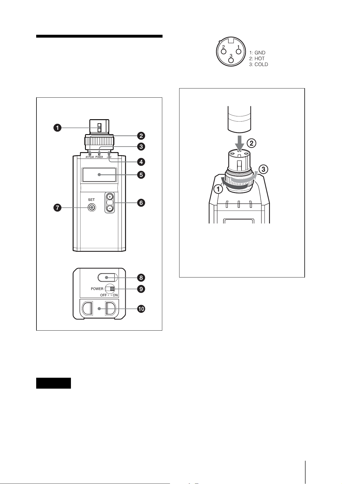
Parts
Identification
Front
To connect a microphone or a cable
Microphone or a cable (optional)
Bottom
a Audio input connector (XLR-3-11C)
Connects a microphone with an XLR-312C-type output connector or an audio
cable with an XLR-3-12C-type connector.
Caution
Be sure that the transmitter is turned off
before connecting a microphone or cable to
the transmitter.
Turn the connector ring clockwise (1)
and insert the microphone or cable
connector into the audio input connector
until it is fully engaged (2). Then turn the
connector ring counterclockwise to
secure the latch (3).
b AF (audio input level) /PEAK
indicator
Lights up green when the signal input is
stronger than the reference level.
Lights up red when the signal input is 3 dB
below the level at which distortion begins.
c POWER indicator
Lights up green when the transmitter is
turned on. When the battery is exhausted,
the indicator starts flashing.
d +48V indicator
Lights up when INPUT LEVEL is set to
MIC and +48 V power is being supplied to
a connected microphone or other device.
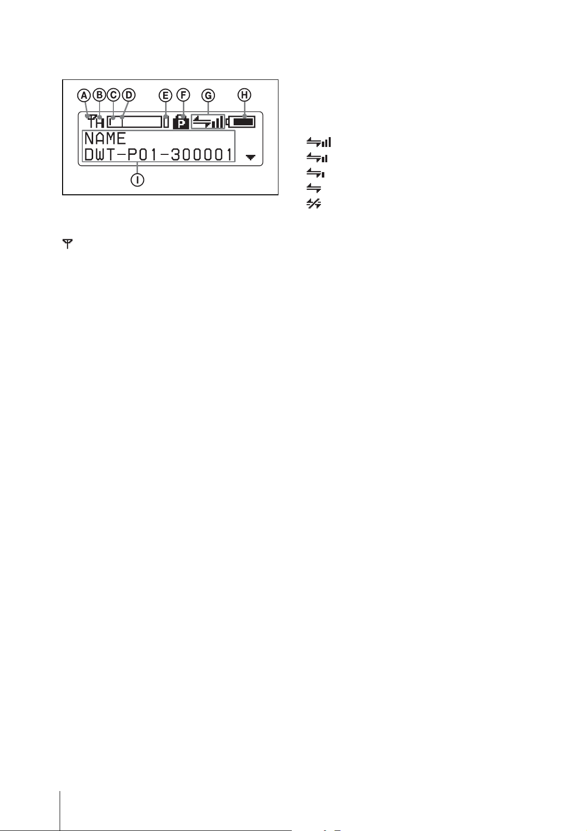
e Display section
A RF transmission indication
Indicates the current transmission status.
: Currently transmitting
—: Transmission stopped
G Wireless remote control condition
indication
Indicates the signal transmission condition
of the wireless remote control function (4
levels).
: Good transmission
: Somewhat good transmission
: Somewhat poor transmission
: Poor transmission
: Unable to communicate with paired
receiver
When the wireless remote control function
is off, this indication does not appear.
B RF (radio frequency) transmission
power indication
Indicates the current transmission power
setting. You can change the setting with the
RF POWER function.
H: Transmitting at 50 mW
M: Transmitting at 10 mW
L: Transmitting at 1 mW
C Audio input level meter
Indicates the input signal level of the audio
input connector.
D Reference level gauge
Indicates the reference input level. When
the attenuation is 0 dB with INPUT LEVEL
set to MIC, –58 dBu (–60 dBV) is indicated.
When LINE is selected for INPUT LEVEL,
+4 dBu is indicated.
E Peak indicator
Warns of excessive input by lighting up
when the signal is 3 dB below the level at
which distortion begins.
H Battery indication
Shows the battery condition.
For details, see “Battery indication”.
I Menu display section
The status of 17 different functions are
displayed here. To select the function, press
the + or – button repeatedly.
For details, See “Setting Menus”.
f + or – button
Selects functions or values shown on the
display.
Holding down the – button while switching
on the transmitter activates the pairing
operation for the wireless remote control
function.
g SET button
Adjusts displayed function settings and
enters the value.
Holding down the SET button while
switching on the power turns the transmitter
on without sending a signal.
F POWER switch lock indicator
Indicates that the POWER switch is locked,
preventing the transmitter from being
accidentally turned off or on.
For details, see “Locking the POWER switch
(POWER SW LOCK)”.
h USB connector (Micro USB)
Use this connector to connect an optional
USB keyboard to carry out menu functions
using key operations. By connecting the
digital wireless receiver to this connector
with the supplied USB cable, you can
exchange the encryption key for encrypted
transmission function.
i POWER switch
Turns the transmitter ON or OFF.
Power Supply
j Battery compartment
Accommodates two LR6 (size AA) alkaline
batteries.
For details on how to insert the batteries, see
“Power Supply”.
The transmitter can operate on two LR6
(size AA) alkaline batteries continuously
for about 3.5 hours at 25°C (77°F).
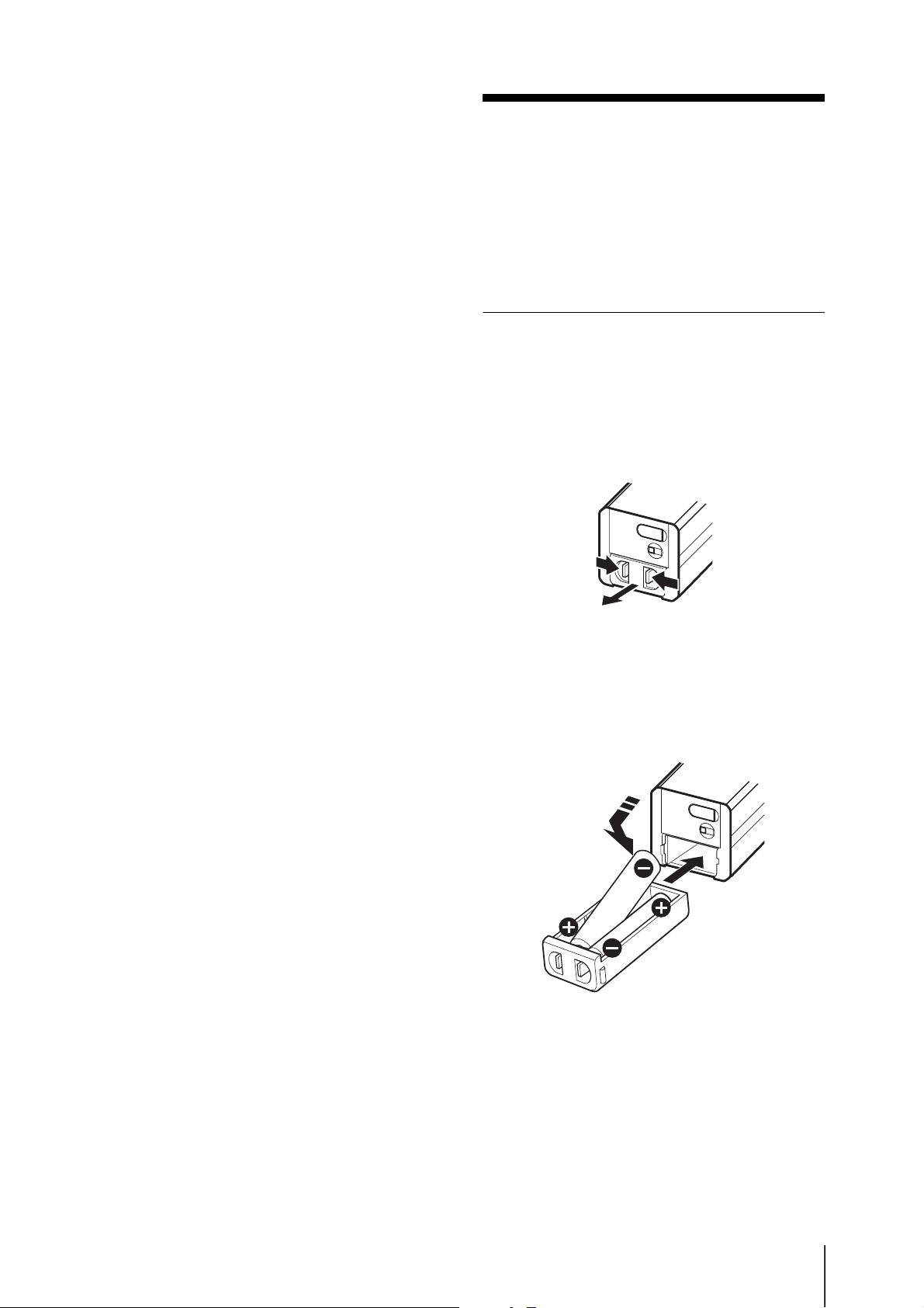
Installing the batteries
1 Squeeze the battery-holder tabs inward
(in the direction of the arrows) and
slide out the battery holder.
2 Insert new batteries, making sure the
polarities are correct, and then return
the battery holder to its original
position.
Battery indication
The power status is indicated by eight level
indications.
Replace both batteries when the battery
indication starts to flash.
Be sure to check the expiration date printed
on the new batteries before using them.

Note
The indication is based on the use of new
LR6 (size AA) Sony Alkaline batteries. An
incorrect indication may result when a
different kind of batteries, a different brand
of batteries or old batteries are used. If you
plan to use the transmitter for a long period
of time, it is recommended that you replace
the batteries with brand new ones.
Setting the
Transmission
Channel
The transmitter provides groups of
interference-free channels. When using
multiple microphones and transmitters at
the same time (simultaneous multi-channel
operations) within the same area, selecting
the same group and using a channel within
that group can prevent signal interference.
To set the transmission channel on the
transmitter, first you select the group and
channel using the RF indicator and
scanning functions on the receiver. Next
you set the group and channel parameters to
match the setting on the receiver.
Selecting the group/
channel
Notes
• Before doing this procedure, use the
BAND function to set the
transmitter to the bandwidth of the
receiver you are using.
• The setting for this function cannot be
changed during actual signal
transmission.
Set the transmitter group (GP) and channel
(CH) as follows:
For details on groups and channels, refer to “Sony
Digital Wireless Microphone System Frequency
Lists” on the supplied CD-ROM.
For details on menu operation, see “Basic Menu
Operations”.
 Loading...