

Sony DWR-S02DN Operating Instructions Manual

Digital Wireless
4-692-879-02 (1)
Receiver
Operating Instructions
DWR-S02DN
© 2016 Sony Corporation

Table of Contents
Features ...................................................................... 3
Parts Identification ................................................... 4
Preparation ................................................................ 5
Attaching to a Camcorder ...................................... 5
Using the DWA-01D/F01D Wireless Adapter ...... 6
Setting the Receiving Channel ................................. 6
Selecting the Frequency Band / Group /
Channel ................................................................ 6
Using the Active Channel Scan Function .............. 7
Using the Clear Channel Scan Function ................ 7
Using the Encrypted Transmission Function ......... 8
Using Secure Key Mode (SECURE KEY) ............ 8
Using Password Mode (PASSWORD) .................. 9
Using a USB Keyboard ........................................... 10
Menu Displays and Detailed Settings .................... 10
Menu Structure and Hierarchy ............................. 10
Basic Menu Operations ........................................ 11
UTILITY Menu ....................................................... 12
Selecting the AES/EBU Output Reference Level
(AES/EBU LVL@MIC) .................................... 12
Selecting the Sync Signal (SYNC SOURCE) ..... 12
Terminating the Sync Signal (WORD SYNC
75ohm) ............................................................... 12
Selecting Output 1 (ANALOG OUTPUT1) ........ 12
Showing the Accumulated Use Time (TIME) ..... 12
Setting the Brightness of the Display
(BRIGHTNESS) ................................................ 13
Automatic Dimming of the Display
(DIMMER MODE) ........................................... 13
Resetting Parameters to their Factory Settings
(FACTORY PRESET) ...................................... 13
Displaying the Software Version (VERSION) .... 13
RX (tuner) 1/2 Menu ............................................... 13
Group/Channel Selection (GP/CH) ..................... 13
Frequency Band Selection (BAND) .................... 13
Active Channel Scanning Function
(ACT CH SCAN) .............................................. 13
Clear Channel Scan Function
(CLR CH SCAN) ............................................... 13
Using the RF Squelch Function
(RF SQUELCH) ................................................ 14
Encrypted Transmission Function
(ENCRYPTION) ............................................... 14
Setting the Audio Codec Mode
(CODEC MODE) .............................................. 14
Display of the Audio Signal Delay Time
(SYSTEM DELAY) .......................................... 14
TX (Transmitter Virtual) 1/2 Menu ...................... 15
Display of the Transmitter’s Name (NAME) ...... 15
Display of the Transmission Power Setting
(RF POWER) ..................................................... 15
Display of Audio Input Level
(INPUT LEVEL) ............................................... 15
Display of the Low-cut Filter Setting (LCF) ....... 15
Display of the Power Save Setting
(POWER SAVE) ............................................... 15
Display of Accumulated Battery Use Time
(TIME) ............................................................... 15
Display of the +48V Power Setting (+48V) ........ 15
Cross Remote (RF REMOTE) ............................. 15
Using the Cross Remote .......................................... 16
Pairing with a Transmitter ................................... 16
Changing the Settings on the Transmitter ............ 17
Group/Channel Setting (GP/CH) ......................... 17
Frequency Band Setting (BAND) ........................ 17
Transmission Power Setting (RF POWER) ......... 17
Audio Input Level Setting (INPUT LEVEL) ...... 18
Low-cut Filter Setting (LCF) ............................... 18
Power-saving Setting (POWER SAVE) .............. 18
+48V Power Setting (+48V) ................................ 18
Cross Remote Setting (RF REMOTE) ................ 18
Audio codec mode setting (CODEC MODE) ..... 18
Block Diagram ......................................................... 19
Troubleshooting ....................................................... 20
Important Notes on Operation .............................. 22
Notes on Using the Receiver ............................... 22
On Cleaning ......................................................... 22
Transmitter software version ............................... 22
Audio degradation due to weak reception ........... 22
Specifications ........................................................... 23
Carrier Frequencies and Channel Steps ............... 24
2

Features
The DWR-S02DN digital wireless receiver is a slot-in type
wireless receiver capable of receiving two channels from
digital wireless transmitters. Used in conjunction with
Sony professional camcorders or the optional DWA-01D/
F01D wireless adapter, the DWR-S02DN enables the
construction of a fully digital ENG/EFP audio system.
This receiver enables the application of multiple channels
over unused television channels through the use of the
built-in Sony original channel plan.
What is DWX?
DWX refers to Sony’s new digital wireless microphone
system. The DWX series reflects Sony’s extensive
expertise in professional microphones and sound design. It
represents a successful blend of Sony know-how, wireless
technology renowned for stability, and cutting-edge digital
audio technology.
In addition to realizing the high sound quality possible
with a digital system, the DWX series supports multichannel simultaneous operation, encrypted transmission,
and metadata transmission for monitoring the status of
multiple transmitters. Using a main link and a separate
additional link, remote control of transmitters from the
receiver is also possible. With its many advanced features,
the system has the potential to revolutionize the workflow
of professional applications.
What is WiDIF-HP?
WiDIF-HP (WiDIF: Wireless Digital Interface Format,
HP: High Profile) is a wireless digital audio interface
format developed by Sony.
It enables highly secure transmission with high sound
quality and low system latency, and supports simultaneous
multi-channel operation.
Rear mounting to camcorders
The DWR-S02DN can be rear-mounted to a range of Sony
professional camcorders - using the DWA-01D/F01D
wireless adapter. When used with a camcorder that has
AES/EBU inputs, full-digital audio recording is also
possible.
Auto channel scanning function
The DWR-S02DN comes with two auto channel scanning
functions that allows for fast, easy and safe frequency
channel changes.
Three audio codec modes
Switch between audio codec modes based on your
operational needs.
For details, see “Setting the Audio Codec Mode (CODEC
MODE)” on page 14.
Compact, lightweight, and rugged design
The DWR-S02DN is highly compact and lightweight,
maintaining a good balance even when mounted on a
camcorder. In addition, it is made of magnesium die-cast
and aluminum, making it extremely rugged and suitable
for the harsh environment.
Easy-to-see, full dot-matrix OLED (Organic
Light-Emitting Diode) display
The quick response of the OLED display enables real-time
operating conditions to be displayed clearly and
accurately.
What is Cross Remote?
Cross Remote is a system that allows transmitters to be
monitored and controlled from a receiver and the Wireless
Studio control software installed on a computer connected
to the receiver.
For example, the settings of a transmitter worn under
clothing can be easily changed over the wireless link.
Preprogrammed wireless channel plans
for simultaneous multi-channel operation
The DWR-S02DN has many preprogrammed channel
groups, meaning combination of wireless channels to
permit simultaneous operation of multiple channels
without intermodulation.
Two-channel slot-in wireless receiver
Despite its dual-channel receiver capability, the DWRS02DN is small enough to be mounted directly in the slot
of the Sony camcorder.
3
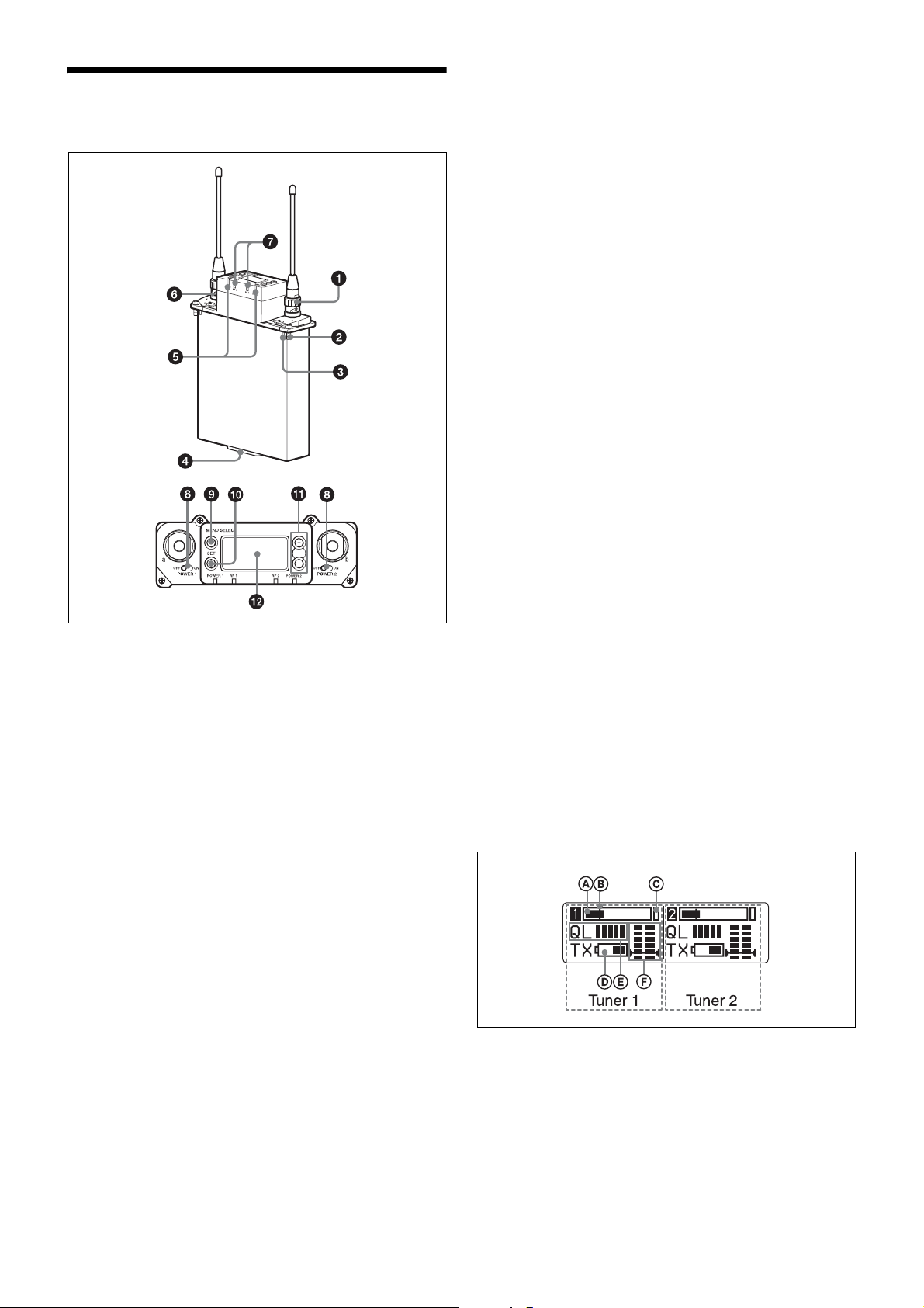
Parts Identification
For details on encryption key exchange, see “Using the
Encrypted Transmission Function” on page 8.
g RF (radio frequency) indicators
Indicate the RF input level of tuner 1 and tuner 2.
The indicators that light up depend on the RF squelch
function setting as follows:
When the RF (radio frequency) squelch level is set to
OFF:
On in green: 25 dBµ or more
On in red: 20 dBµ to 25 dBµ
Off: Less than 20 dBµ
When the RF (radio frequency) squelch level is set to 20
dBµ:
On in green: 30 dBµ or more
On in red: 20 dBµ to 30 dBµ
Off: Less than 20 dBµ
h POWER switches
Turn tuner 1 and tuner 2 on or off individually.
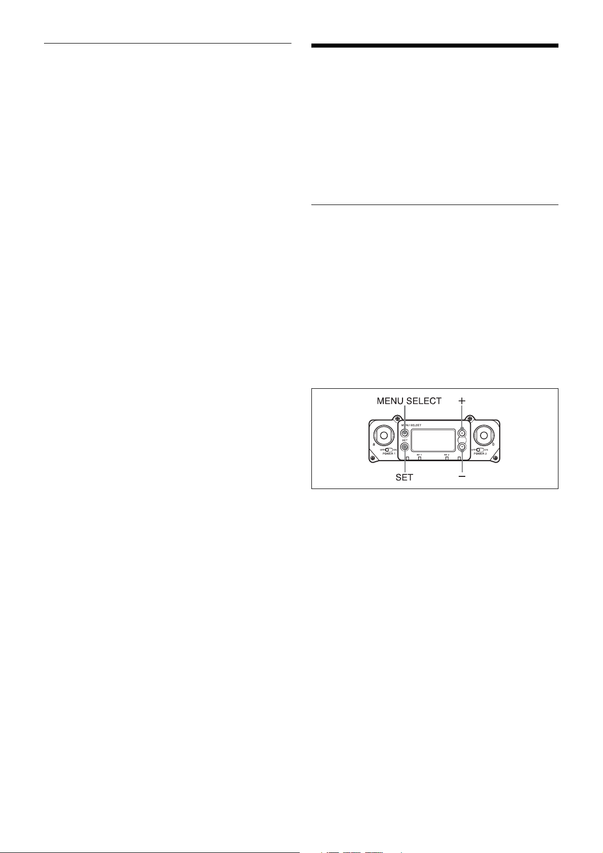
i MENU SELECT (menu selection) button
Selects the displayed menu.
a Antenna and antenna connector (BNC type)
Connect the supplied antenna here.
b Mounting screw
Use to attach the receiver to a camcorder or DWA-01D/
F01D wireless adapter.
c Compatibility pin
Prevents the attachment of an incompatible camcorder or
adapter.
d Accessory connector
Use to connect the receiver to a camcorder or DWA-01D/
F01D wireless adapter. Power, audio, and control signals
are sent through this connector.
e POWER indicator
Lights up green when the power is on.
The POWER1 and POWER2 indicators indicate the power
status of tuner 1 and tuner 2, respectively.
j SET button
Changes the item to be set or enters the selected function
or parameter value.
k + or – button
Use to select a function or value.
If you set the POWER switch on tuner 1 or tuner 2 to ON
while holding down the + button, the tuner that you turned
ON will begin the scanning operation of the clear channel
scan function.
If you set the POWER switch on tuner 1 or tuner 2 to ON
while holding down the – button, the tuner that you turned
ON will begin the pairing operation of the wireless remote
control function.
l Display section
Meter display
f USB connector
Connecting an optional keyboard to this connector allows
menu operation to be performed on the keyboard.
Connecting the transmitter to this connector through the
supplied USB cable allows an encryption key to be
exchanged with the transmitter.
For details on the use of a USB keyboard, see “Using a
USB Keyboard” on page 10.
A Audio input level meter
Indicates the input signal level.
B Reference level gage
Indicates the reference input level.
–58 dBu (–60 dBV) is indicated when the input level is set
to “MIC” on the transmitter, and +4 dBu when the input
level is set to line.
4
C Peak indicator
Warns of excessive input by lighting up when the signal is
3 dB below the level at which distortion begins.
D Battery indication
Based on metadata from the transmitter, shows the
transmitter’s battery condition according to 8 level
indications.
Replace both batteries when the battery indication starts to
flash.
For details on how to change the batteries on the
transmitter, refer to the operating instructions supplied
with the transmitter.
E Signal quality level meter
Indicates the quality of the RF signal reception.
The occurrence of many data errors during a given interval
reduces the height of the bar graph.
This meter allows you to monitor signal deterioration that
may occur when there is noise or when the transmitter is
too far from the receiver.
F RF level meter
Indicates the RF input level. The number of segments that
light up depends on the input level.
When the squelch function is set, the squelch level is
indicated on the RF level meter.
When the RF input level drops below the squelch level, the
output signal is muted.
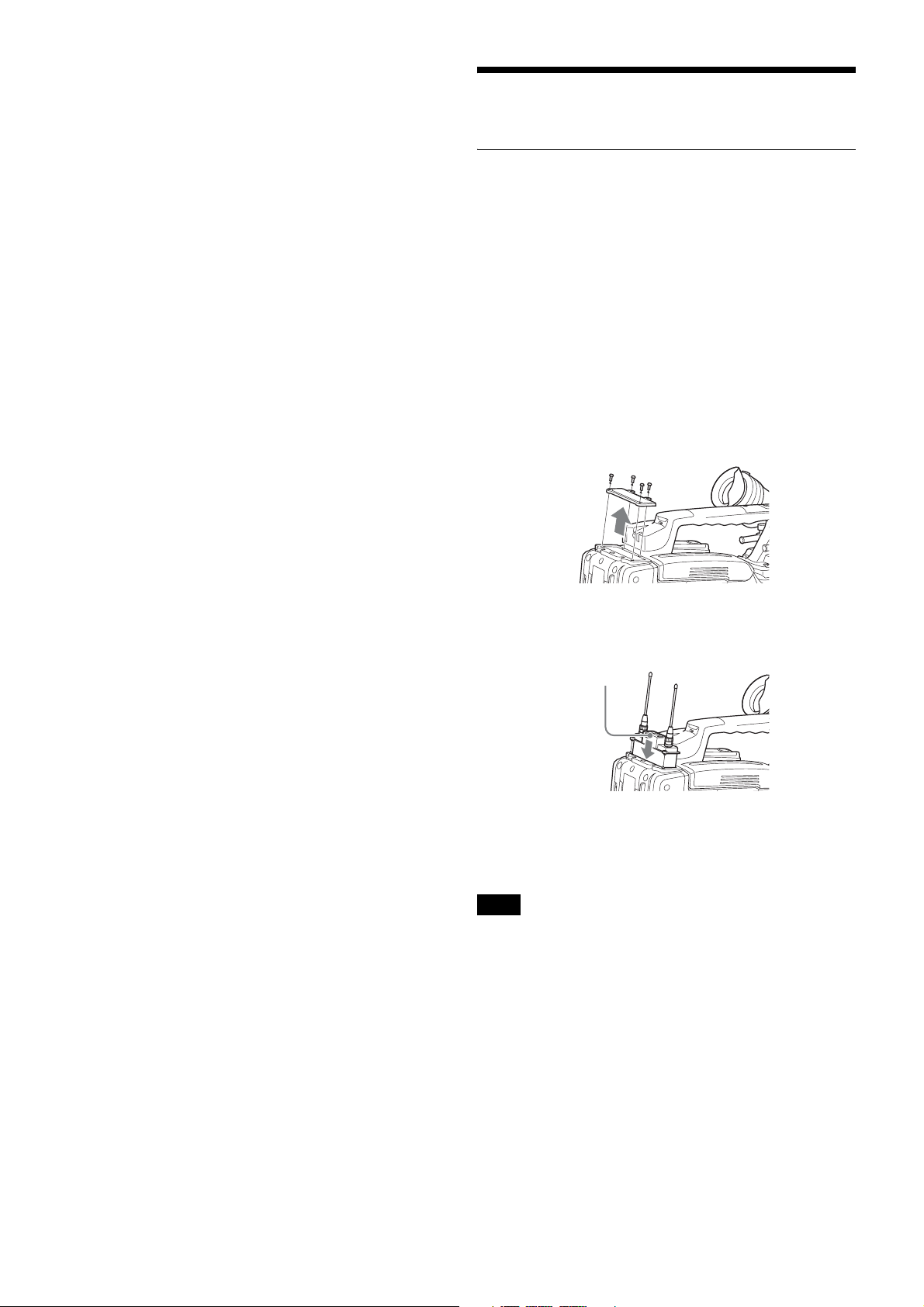
Preparation
Attaching to a Camcorder
This receiver can be inserted into a slot provided on
compatible Sony camcorders.
The audio signal, which is converted to digital by the
digital wireless transmitter, can be recorded as is to the
camcorder, allowing you to create a fully digital system.
1
Remove the cover from the slot for the wireless
receiver on the camcorder, and insert the receiver into
the slot.
To avoid inserting the receiver in the wrong direction,
confirm the location of the mounting screws and
compatibility pin before inserting the wireless
receiver.
2
After inserting the receiver completely into slot,
securely fasten the four mounting screws.
Receiver
For details about operating the camcorder with the
receiver, refer to the operating instructions supplied with
the camcorder.
Note
If the camcorder is not compatible with the receiver, the
compatibility pin on the receiver will make it impossible to
insert the receiver into the slot.
For details on compatible camcorders, consult a Sony
sales representative.
5
Using the DWA-01D/F01D Wireless Adapter
Attaching the receiver to the DWA-01D/F01D wireless
adapter allows them to be used as a portable wireless
receiver.
For details, refer to the operating instructions supplied
with the adapter.
Setting the Receiving Channel
The receiver provides groups of channels for interferencefree transmission. When using multiple wireless
microphones and transmitters (simultaneous multichannel operations) within the same area, selecting the
same group and using a channel within that group can
prevent signal interference.
Selecting the Frequency Band / Group / Channel
Set the frequency band (BAND), group (GP), and channel
(CH) as follows.
For details on the groups and channels included in each
frequency band, refer to “Sony Digital Wireless
Microphone System Frequency Lists” on the supplied CDROM.
For details on menu operations, see “Basic Menu
Operations” on page 11.
1
Press the MENU SELECT button repeatedly until the
RX1/RX2 menu is displayed.
2
Press the + or – button repeatedly until the BAND
screen is displayed.
3
Hold down the SET button until the item to be set
flashes.
4
Press the + or – button repeatedly to select a frequency
band.
5
Press the SET button to confirm the selection.
6
Press the + or – button repeatedly until the GP/CH
screen is displayed.
7
Hold down the SET button until the item to be set
flashes.
8
Press the + or – button repeatedly to select a group.
9
Press the SET button to confirm the selection.
6

The channel indicator starts flashing.
10
Press the + or – button repeatedly to select a channel.
5
If you decide on that frequency after checking it out,
press the + or – button repeatedly to select SET, and
then press the SET button.
11
Press the SET button to confirm the selection.
When the wireless remote control function is
operating:
When you change the BAND/GP/CH setting on the
receiver, you can send the BAND/GP/CH setting to the
transmitter that is paired with the receiver.
Note
If the receiving channel (CH) configured on the receiver is
a channel for which use with the wireless remote control
function is restricted on the transmitter side, the
UNMATCH screen appears.
In such cases, change the receiving channel on the
receiver. If you want to use the restricted channel, set
REMOTE to OFF in the transmitter’s menu to release the
channel restriction, and manually configure the
transmitter’s channel.
About use of the same group and channel
by adjacent systems
When the same group and channel are being used by two
or more systems that are within sight of each other and are
separated without partitions or obstacles in wide open
place, each system should be at least 100 meters away
from the others to avoid interference.
Using the Active Channel Scan Function
This function scans for a Sony digital wireless frequency
from the frequency lists within the GP (group) selected
during the GP/CH selection function.
To search for another frequency, press the + or –
button repeatedly to select CONTINUE, and then
press the SET button.
Note
If a Sony digital wireless frequency within the group is not
found by the second try, scanning is cancelled.
Using the Clear Channel Scan Function
This function searches for a channel that is not being used
by another wireless device or by a TV station. This
function makes it easy to find an available channel to allow
the wireless microphone to be used without interference.
The function searches for an empty channel among the
registered frequencies within the GP (group) selected by
the GP/CH selection function.
In addition to using the following procedure, you can also
set the POWER switch on tuner 1 or tuner 2 to ON while
holding down the + button to start the clear channel scan
function on the tuner that you turned ON.
1
Press the MENU SELECT button repeatedly until the
RX1/RX2 menu is displayed.
2
Press the + or – button repeatedly until the CLR CH
SCAN indication is displayed.
3
Hold down the SET button until the item to be set
flashes.
4
In the CLR CH SCAN indication, press the + or –
button repeatedly to select YES.
Required condition for the detection:
• Sony digital wireless signal
• Above the RF squelch level of the receiver
• The setting of the encrypted transmission function is
correct
• The audio codec mode settings match
1
Press the MENU SELECT button repeatedly until the
RX1/RX2 menu is displayed.
2
Press the + or – button repeatedly until the ACT CH
SCAN indication is displayed.
3
Hold down the SET button until the item to be set
flashes.
4
Press the + or – button repeatedly to select YES.
Scanning starts. When a Sony digital wireless
frequency is detected, scanning stops and the
frequency is displayed.
If you select NO, the scanning function will be
cancelled.
Scanning starts. When an empty channel is detected,
scanning stops and the frequency is displayed.
If you select NO, the scanning function will be
cancelled.
5
If you decide to use that channel, press the + or –
button repeatedly to select SET, and then press the
SET button.
When the wireless remote control function is
operating, the group/channel setting can be sent to the
transmitter.
To search for another empty channel, press the + or –
button repeatedly to select CONTINUE, and then
press the SET button.
Notes
• If an empty channel within the group is not found by the
second try, scanning is cancelled.
• If the receiving channel (CH) configured on the receiver
is a channel for which use with the wireless remote
control function is restricted on the transmitter side, the
7

UNMATCH screen appears.
In such cases, change the receiving channel on the
receiver. If you want to use the restricted channel, set
REMOTE to OFF in the transmitter’s menu to release
the channel restriction, and manually configure the
transmitter’s channel.
Using the Encrypted Transmission Function
This receiver is capable of receiving scrambled signals
from Sony digital wireless transmitters. This function
prevents hacking of the signal.
To use this function, select one of the following encrypted
transmission modes:
Secure key mode: A secure key that is automatically
generated by the transmitter is used by both the transmitter
and receiver in this one-to-one encrypted transmission
method.
Password mode: You choose a password of up to eight
characters that can be set for multiple transmitters and
receivers. This enables encrypted transmission to be
conducted within a group.
Note
Make sure the same mode is set on the transmitter and
receiver.
Using Secure Key Mode (SECURE KEY)
Use this mode for one-to-one encrypted transmission
between one transmitter and one receiver.
An encryption key that cannot be read from the outside is
automatically generated by the transmitter. This key is
transmitted to the receiver through a USB connection or
the RF REMOTE function, enabling encrypted
transmission to take place.
The encryption key used by the transmitter and receiver is
newly generated for each key transmission, resulting in
highly secure communication.
The encryption key used between the transmitter and the
receiver is saved when the power is turned off, so the
encrypted transmission can be resumed the next time the
power is turned on.
1
Preparing the receiver (this unit)
1 With the ENCRYPTION indication on (in the
RX1/2 menu), hold down the SET button until the
item to be set flashes.
2 Press the + or – button repeatedly to select
SECURE KEY, and then press the SET button.
2
Preparing the transmitter
Set SECURE KEY on the transmitter that will transfer
the encryption key.
For details on transmitter operations, refer to the
operating instructions supplied with the transmitter.
3
Exchanging the encryption key
On the receiver, select USB or REMOTE (wireless
remote) as the method for encryption key exchange.
8
 Loading...